theoreticandexperimentalstudiesonthecastingof...
TRANSCRIPT
Hindawi Publishing CorporationModelling and Simulation in EngineeringVolume 2012, Article ID 362197, 7 pagesdoi:10.1155/2012/362197
Research Article
Theoretic and Experimental Studies on the Casting ofLarge Die-Type Parts Made of Lamellar Graphite Grey Pig Ironsby Using the Technology of Polystyrene Moulds Casting fromTwo Sprue Cups
Constantin Marta, Ioan Ruja, Cinca Ionel Lupinca, and Monica Rosu
Department of Engineering, University “Eftimie Murgu” of Resita, Piata Traian Vuia, nr.1-4, 320085 Resita,Jud. Caras-Severin, Romania
Correspondence should be addressed to Constantin Marta, [email protected]
Received 30 April 2012; Revised 30 August 2012; Accepted 13 September 2012
Academic Editor: Philippe Boisse
Copyright © 2012 Constantin Marta et al. This is an open access article distributed under the Creative Commons AttributionLicense, which permits unrestricted use, distribution, and reproduction in any medium, provided the original work is properlycited.
This paper presents a comparative analysis between the practical results of pig iron die-type part casting and the results reachedby simulation. The insert was made of polystyrene, and the casting was downward vertical. As after the part casting and heattreatment cracks were observed in the part, it became necessary to locate and identify these fissures and to establish some measuresfor eliminating the casting defects and for locating them. The research method was the comparisons of defects identified throughverifications, measurements, and metallographic analyses applied to the cast part with the results of some criteria specific tosimulation after simulating the casting process. In order to verify the compatibility between reality and simulation, we thensimulated the part casting respecting the real conditions in which it was cast. By visualising certain sections of the cast partduring solidification, relevant details occur about the possible evolution of defects. The simulation software was AnyCasting,the measurements were done through nondestructive methods.
1. Introduction
The pearlitic grey pig irons constitute of family of ferrousmaterials with a wide range of mechanical properties, beingusing in the manufacture of bed frames, cylinder covers, dies,mechanisms bodies, pistons, cylinders [1]. The propertiesof strength, tenacity, and plasticity of the lamellar graphitepig irons are relatively low. These alloys exhibit uniqueproprieties of use due to the presence of graphite under theform of lamellas, such as: capacity of vibration damping,“lubricant” character; high processability; good resistance toabrasion; good corrosion resistance; preservation of prop-erties in the temperature range from −100◦C to +350◦C;very good resistance to heat shocks, very good castability.The parts are produced by casting in moulds, which makesthem usable in the manufacture of mechanical components.Other advantages are the low cost and the wide scope of uses.The cooling rate of cast parts may affect the toughness and
structure of the materials. In the present case we executeda die of lamellar graphite pig iron, toughness >150 <300HB mechanic strength >500 <1000 N·mm−2. This group ofpig irons represents the quality of high strength generallyobtained through a pearlitic die, which is relatively tough andhas low tenacity and good processability. The casting of largedie-type parts, approximately 11,000 kg raises a problem ofthe design and elaboration technology are not respected,especially the procedures of pig irons modification. Thetechnology of casting in polystyrene moulds with two runnerbasins exhibits some particularities with major consequenceson the parts quality.
2. Analysis of the Cast Part
Table 1 shows the chemical composition in % weight [1, 2],as well as the execution of the part according to the own
2 Modelling and Simulation in Engineering
Table 1: Chemical compositon of material, (wt.%).
C Si Mn P S Cu
EN GJL 200 3.15–3.45 2.00–1.40 0.60–0.80 max 0.200 0.05–0.100 —
casting technology, specific to the casting in polystyrenemoulds. The charge was cast through two runner basins.
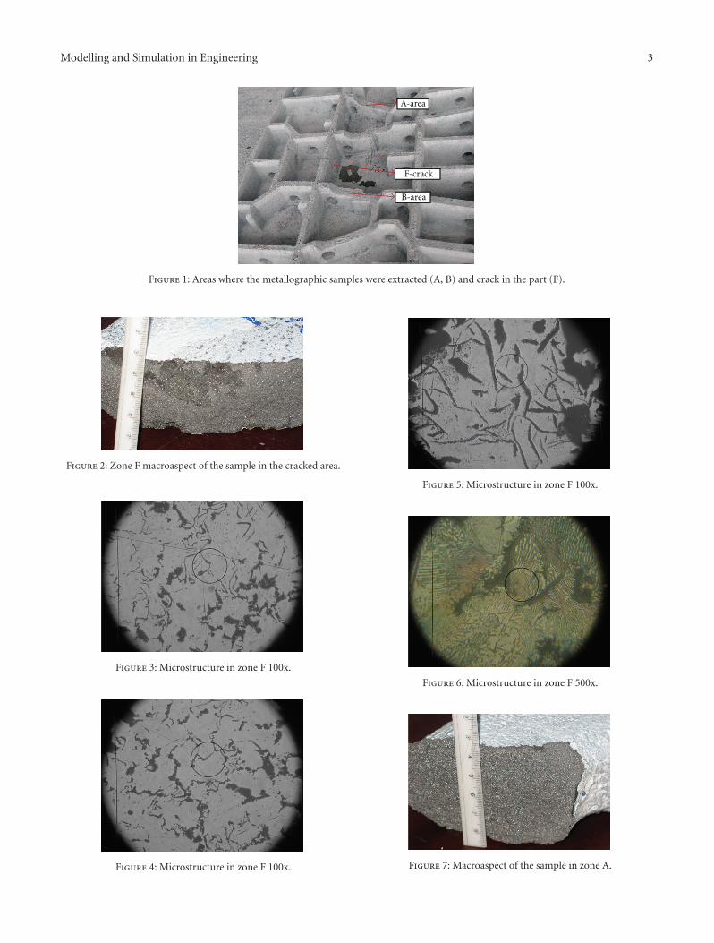
After casting the visual verification of the cast surface andthe location of possible casting defects were carried out. Thedefect in the cast part occurs under the form of a transversalcrack in the median area of the part, on the horizontal baseplate, 2 to 2.5 mm width and 1500 mm long, defect whichappears in Figure 1. Figure 1 shows the areas where one hasextracted the metallographic samples, marks: A, B, and F.
The analysis contains study of the design of the partgeometry by visual analysis and extraction of metallurgicsamples from the area of the defect. From the part designviewpoint, we find that the joining angle between ribs (fins)and the body of the part is 90◦ without junctions, and theribs have widths ranging between 25 mm and 90 mm withoutrespecting the basic principles of the casting moulds [3, 4].
3. Macro- and Microstructural Analysis
According to Figure 1, three samples were extracted fromthree different zones: (1) F-position middle zone where thecrack occurred, (2) final zone A, and (3) end zone B.
3.1. Macro- and Microstructural Analysis of Area F. Figure 2shows the sample extracted from area F, that is, the middlearea of the part where the crack occurs. This area is wherethe two metal fronts merged. The casting was done by usingtwo sprue cups placed at the ends of the casting mould.
Figure 2 presents the middle area, that is, the zone wherethe crack occurs and at the same time the joining zone of thetwo jets (flowing currents) of the liquid pig iron. This zoneexhibits nonmetallic inclusions such as oxides, sulphides, andsmall gaseous inclusions (air bubbles) which may constitutecrack triggers in the conditions of the existence of very highinternal strains generated by a braked contraction duringsolidification and cooling. One should remark the area ofprimary graphitisation in the insufficiently developed eutec-tic cells, due to the low casting temperature (1220◦C), andto a accelerated rate cooling area, as well as to a weakmodification of the pig iron. By exceeding the time betweenmodification and casting by over 15 minutes, the effect ofthe modification is very much attenuated [4]. There occuralso air bubbles and oxides, as the middle area is the joiningzone of the jets of liquid alloy come from the two spruecups. Due to the fact that the part casting was made withtwo sprue cups we encounter two liquid fronts with differenttemperatures (of which one has the temperature below thetechnological casting level), as well as the differences inchemical composition. All these factors are potentially prob-abilistically generators of the defects from the above macro-scopic image. The area where the defect is not oxidised whichshows that the crack occurred at cold.
In Figure 3 one observed a microstructure of hypereutec-tic grey pig with metallic mass of pearlitic base, according to
the chemical composition analysed, confirms the weak evo-lution of the separation of primary graphite, in the processof passing through the solidification range. Obviously thecasting temperature was lower than the technological one, aswell as the effect of the modification which is inefficient. Thezone exhibits separations of lamellar graphite of semiarchedshape and nest-shaped graphite separations. One witnessesthe occurrence of only very small modified lamellar graphite(glm) separations. The second sample, Figure 4, confirms thecause of the material defect. The degenerate shape of primarygraphite can be remarked. It may occur in the structureof the pig iron of the second fusion only if the loadingof the elaboration furnace was made with furnace raw pigiron, but not of high purity; the primary, hereditary pigiron separates following the incomplete dissolution of thegraphite from the first-fusion pig iron-furnace raw iron pig,at the melting of the metallic charge; the seeds or grainsof primary hereditary graphite may lead to the increase ofprimary hereditary graphite separations, at the solidificationof the second-fusion grey pig iron; we witness a directingof carbon atoms from the melt toward theses grains with adistribution towards the limit of the eutectic cell very closeto the typical shape of the interdendritic graphite.
The microstructure in Figure 5 indicates a correct sepa-ration of secondary graphitisation, with around 50 µm-longgraphite lamellas, but not with rounded points, as well as arather inappropriate length, considering the part mass (11t),which at a slow cooling would have led to the enlargement ofthe graphite lamellas to around 100–150 µm. They are shapesof separations of modified lamellar graphite. In Figure 6 weremark that the metallic basic mass is pearlite.
3.2. Macro- and Microstructural Analysis of the Part in ZoneA. In Figure 7 the macroaspect is appropriate, typical forpearlitic grey iron pig with a granulation specific to thestudied make of pig iron.
The sample in Figure 8 is without reactive attack andallows the observation of the graphite distribution, whichis lamellar, with appropriate length, but with smaller widthsand without rounded points (it produces the effect of growthin the basic metallic mass). This leads to the conclusionthat we need a better modification in the casting ladle,with FeSi75, and to the setting of an appropriate castingtemperature. The following areas examined in Figure 8(microstructure in zone A) and Figure 9 (microstructure inzone A) validate the conclusions. The analysis with reactiveshighlights a pearlitic base metallic mass, Figure 9.
3.3. Macro- and Microstructural Analysis of the Part in ZoneB. In Figure 10 the macro aspect is appropriate, typical forthe pearlitic grey pig iron with a granulation specific to thestudied make of pig iron.
In Figure 11 we remark the size of the graphite lamellas,smaller than in the pig iron from the other runner basin,
Modelling and Simulation in Engineering 3
A-area
F-crack
B-area
Figure 1: Areas where the metallographic samples were extracted (A, B) and crack in the part (F).
Figure 2: Zone F macroaspect of the sample in the cracked area.
Figure 3: Microstructure in zone F 100x.
Figure 4: Microstructure in zone F 100x.
Figure 5: Microstructure in zone F 100x.
Figure 6: Microstructure in zone F 500x.
Figure 7: Macroaspect of the sample in zone A.

4 Modelling and Simulation in Engineering
Figure 8: Microstructure in zone A 100x.
Figure 9: Microstructure in zone A 500x.
Figure 10: Macroaspect of the sample in zone B.
Figure 11: Microstructure in zone B 100x.
Figure 12: Microstructure in zone B 100x.
possibly more weakly modified and colder cast. The micro-analysis in the adjacent area, Figure 12, exhibits a bettermicrostructure than the previous one, not by much, butenough to draw the conclusion of a weaker thermal-chemicalhomogenisation, at sprue cup no. 1. The microanalysis withreactives shows a pearlitic base metallic mass, with areas ofbinary phosphorus eutectic.
4. Conclusions
From the macroanalysis of the part we remarked the defi-ciencies of design, moulding and elaboration which triggerthe occurrence of the defect:
(i) T-joinings between the walls of the part with greatdifferences in widths (ribs and base plates);
(ii) the crack is caused by a braked contraction triggeredby the ribs-walls and the use of certain cores—the mixture mould which does not enable the freecontraction of the part (noncompressible moulding-coring mixtures);
(iii) a high amount of internal strains was accumulatedon the part base plate as a result of the brakedcontraction at solidification and cooling;
(iv) it is possible that the crack started from some triggers- internal casting defects: nonmetallic inclusions orair bubbles and even the shape of the phosphorouseutectic, which may constitute strain concentrators;we do not analyse the surface defects (there are many)which negatively influence the mechanic characteris-tic to a great extent;
(v) the crack does not start and does not pass through theorifices of the ribs because (fact proved experimen-tally) the holes are limits (obstacles) for the fissurespropagation;
(vi) the execution of the model is inappropriate because atthe walls joints one has not manufactured adequatejunction rays which would have allowed the partialelimination of the formation of corner cavities,taking into account also the fact that having joinedwalls of different width stressed the tendency offormation of thermal knots, corner cavities, and

Modelling and Simulation in Engineering 5
axial microcavities (see the simulation, especially thetemperature variation during filling);
(vii) the middle area, that is, the zone where the fissureoccurs and at the same time the merging area of thetwo jets (flowing currents) of the liquid pig ironexhibits nonmetallic inclusions oxides, sulphides,and small gaseous inclusions—air bubbles—whichmay constitute fissure triggers under conditions ofvery high internal strains generated by a brakescontraction during solidification and cooling;
(viii) there occur areas of primary graphitisation in insuffi-ciently developed eutectic cells, due to the low castingtemperature (1220◦C), and to a cooling area withaccelerated rate;
(ix) the inefficient modification of the pig iron and theexceeding of the delay between modification andcasting, over 15 minutes;
(x) due to the fact that the part casting was made withtwo sprue cups, we encounter two liquid fronts of dif-ferent temperatures (of which one liquid front has thetemperature below the technological casting level), aswell as the differences in the chemical composition.
5. Analysis of the Possibility of DefectPrediction Using the Simulation of Castingand Solidification of the ENGJL 200 Pig Iron
All software for simulating alloys casting and solidificationhas 4 main modules, that is, [2, 5]:
(i) database, where the materials are found with theirphysical and chemical properties;
(ii) preprocessor, where we introduce the parametersnecessary to the simulation, that is, type of alloy,properties of the casting mould, alloy temperature,mould temperature, coefficients of heat transfer,specific coefficients which may determine defects andmechanical properties;
(iii) solver;
(iv) postprocessor, which presents the results of the sim-ulation based on the data introduced by the operator.
It is important to point out that the assessment of thepart cast through classical methods and then subjected tosimulation results in obtaining certain data which help a lotthe user of the software to make the best predictions. Asshown in point 2, the second section of the study refers tothe simulation of the part casting under conditions identicalwith those in which the analysed part was cast. The castingwas done in polystyrene mould with furanic resin cores. Thecasting temperature was of 1250◦C, then alloy is EN GJL 200grey pig iron, the chemical analysis shown in Table 1. Thecasting of the part was done with two sprue cups, technologypresented in Figure 13, where in red we see the position of thetwo runner basins, and of the two mould feeders. The castingwith two basins was chosen as the mass of the part togetherwith the casting network is 12,000 kg.
Basin 1
Basin 2
Figure 13: Presentation of the casting model with two basins.
Contact zone
Figure 14: Convergence area of the two front.
The casting of the part was made with two basins, weencounter two liquid fronts with different temperatures (ofwhich one liquid front with the temperature below thetechnological casting level), as well as differences in thechemical composition.
In the case of casting in polystyrene moulds the feedingis made from the upper section through a feeding networkresulting in the downward casting towards the base of thecasting mould [6]. Consequently the filling of the mouldis made from base to the upper part. Figure 14 shows thesimulation of the pig iron filling from two sprue cups,using the filling sequence criterion [1, 6]. As remarked, thetwo liquid fronts converge in the middle area of the part,where the casting defect appears. By analysing the process,according to the colour code displayed in the left side, wefind that the most rapid filling takes place in the feedingnetwork at 0.0011-second time, in the area indicated withthe red arrow the liquid from basin 1 meets the liquid frombasin 2 after around 11,7036 seconds. Moreover, we remarkin the same area a turbulence specific to the encounter of twoliquid jets. Figure 14 does not show all the filling sequences,we selected those which represent the most accurately themoment of interest.
Another criterion used and presented in Figure 15 isthe retained melt volume, measured in cm3 of volume ofliquid metal retained in certain areas and is used in orderto visualise the zone where liquid volumes remain, that is,

6 Modelling and Simulation in Engineering
Figure 15: The retained melt volume criterion.
which zone solidifies more slowly than the others. Anotherinterpretation refers to the fact that it shows the areas thatretain the largest quality of liquid metal. In the medianarea, where the two fronts unite, the volume of liquidmetal ranges between 312,499 and 1,093,742 cm3 at a totalvolume of 10,791,170,000 cm3. One remarks the separationof two fronts of liquid that will contract later on fromthe median area, which cross the thermal area from thesolidified phase, where the mechanic strength is reducedand the local wall width also small. This fact leads to thepredisposition to cracking of the part as a result of theexistence of uncompensated mechanical strains [3, 5].
This situation is favoured both by the metallographicmicrostructure, made of primary graphite separations,within insufficiently developed lamellas, as well as by the highrate of passage through the solidification range. Moreover,the very median zone, as it has the less ribs and is by30 mm thinner compared to the neighbouring areas, doesnot enable a sufficient mechanical consolidation at thepassage through the solidification range. This leads us to theassumption of the existence of a prefissured state, even fromthe solidification period [7].
In this state the internal tensions generated by theinappropriate design of the model, the lack of chemical andthermal homogeneity may pass unobserved at the extractionfrom the mould, during painting (grounding), and the defectrisks to be amplified during later manipulation or duringtransport.
So in Figure 16 we see in the preprocessor anotherrelevant criterion, that is, the temperature variation duringthe solidification of the casting mould. The solid of the castpart subjected to simulation was made after measurementsperformed on the cast part. The solid thus realised wasintroduced in preprocessor and we applied the conditionof real casting parameters. Thus we find design errors, thatis, the left and right ribs are 50 mm thick and the middleone is 25 mm thick. Consequently, the middle area coolsmore rapidly than the side ones, which cool more slowly.Moreover, the distortions generated by the differentiation ofsolidification in time and constrained by the rigidity of themoulding mixture, generates local, uncompensated tensions[8]. The criterion “temperature variation during the alloymould filling” show that the filling time of the mould isof 373,537 seconds, that is 6,21 minutes. We may deducevery easily also the filling rate. At this value filling is 100%
Figure 16: Temperature variation during alloy solidification.Section in the defect zone.
Figure 17: Temperature variation during alloy solidification.Meshed section in the defect area.
and we remark a 30% solidification, which explains thatduring the part filling the solidification processes also start.By analysing the criterion according to the colours codedisplayed in the left side, Figures 16 and 17, the solidificationstarts from the lateral sides of the part towards the middle,the temperature ranging between 1147◦C (blue-colouredareas) and 1250◦C (white-coloured areas). The presence of1250◦C temperatures especially in the joining areas betweenribs points out the presence of heat knots in the part. Startingfrom this fact, simulation shows that fissures are likely tooccur starting from the “+-” or “T-” shaped joints of thethick walls (ribs), with the same wall thickness or withdifferent thicknesses, and even in the middle areas of thethick walls which solidify among the last areas; the thermalknot occurs in joints [9].
Grosser seeds or grains are formed preponderantly in theribs situated towards the central part of the part where thesolidification-cooling rate and the aforementioned joints inthe walls (T-shaped heat knot) and where it is lower than inthe rest of the part; the higher the cooling rate, the smaller thesizes of grains (but we must be careful, as a very high coolingrate risks to lead to the separation of free cementite).
Figure 17 shows a section and the meshed perspective,which allows a more detailed visualisation of the area ofinterest. By comparing the colours of certain zones of thepart with the colour code in the left side, we can study thesolidification and cooling of the part, and we remark that

Modelling and Simulation in Engineering 7
the solidification front starts from the extreme sections ofthe part and especially from the sections in contact with theatmosphere. The area which solidifies the most rapidly is thatwith the thinnest wall [10].
One proceeded to the nondestructive control of the part,to the identification and location of other hidden castingdefects. One measured the inductivity of different areas ofthe part, and found a predisposition to defects in the medianarea, where the measured items exhibited higher values.
5.1. Conclusions. The simulation software cannot exhibitaspects related to the nonobservance of the technology ofpig iron elaboration. By introducing the parameters of thecast part in the software preprocessor and the display of theresults in the postprocessor we get an image very close toreality:
(i) simulation highlights the convergence area of thetwo liquid fronts, zone which, by measurements,coincides with the position of the defect in the castpart;
(ii) it presents by the analysis of the solid all the designdeficiencies, that is, the “+” or “T” joints of the thickwalls, zones solidify among the last;
(iii) the presence of 1250◦C temperatures especially in thejoining areas between ribs highlight the presence ofheat knots in the part.
6. Final Conclusions
Following the analysis of the simulation results and of con-clusions in point 4 and point 5.1 some proposals resulted inview of enhancement the casting technology:
(i) it is necessary to modify the part execution design, byincreasing the wall thickness in the defect occurrencearea;
(ii) in order to have a high quality of the cast iron, it isnecessary to correctly apply the modification tech-nology, and the time between modification andcasting must be observed;
(iii) casting the part at a temperature which should takeinto account the heat losses caused by the transfer ofthe locked form the furnace in the ladle or sprue cup.The recommended temperature in this situation is of1350◦C;
(iv) due to the fact that the part casting was performedwith two runner basins, two liquid fronts of differenttemperatures converge; consequently it is requiredthat the temperature of the two liquid fronts be equal,as well as their chemical composition;
(v) a series of anomalies found may be avoided by mod-ifying the moulding-casting technology and the useof compressible moulding mixture (preferably frommoulding mixtures bound with classic inorganicbinders) if we are interested in the part compactnessand metallographic structure;
(vi) technological control of heat knots may be done bybuilding some vent holes at moulding-casting, placedon the wall joints;
(vii) it is necessary to correct the moulding-casting tech-nology, by correcting the construction of the model,with the realisation of junction rays on the model andmanufacturing air vents made of the same material ofthe model, alterations which also lead to the modifı-cation of the mould execution;
(viii) it is necessary to build a new polystyrene model;
(ix) it is required to manufacture a new part with the up-dated model.
By comparing the simulation results with the practicalones and vice-versa, the application of simulations of somecast parts provide the user with a very accurate instrumentfor the anticipation of defects and their apparition and at thesame time leads to the building of a very useful database.
References
[1] SR UNE EN, 1560:2011 Founding—designation system forcast iron—materials symbols and material numbers, 2011.
[2] AnyCasting, DataBase, Advanced Casting Simulation Soft-ware, version 3.10, 2009.
[3] M. Skarbinski, Constructia pieselor turnate si proiectarea for-melor (traducere din limba polona), Technical Editions, Bucha-rest, Romania, 1967.
[4] C. Stefanescu, C. Cosneanu, and V. Dumitrescu, Indrumatorulproiectantului de tehnologii ın turnatorii, vol. 1, TechnicalEditions, Bucharest, Romania, 1985.
[5] E. Piwowarsky, Fonte de inalta calitate, Technical Editions,Bucharest, Romania, 1967.
[6] AnyCasting, Advanced Casting Simulation Software, version3.10, 2009.
[7] C. Marta, Aplicatii in AnyCasting, Efimie Murgu Editions,2011.
[8] B. Liu, H. Shen, and W. Li, “Progress in numerical simulationof solidification process of shaped casting,” Journal of MaterialsScience and Technology, vol. 11, pp. 313–322, 1995.
[9] I. Ciobanu, M. Chisamera, S. I. Munteanu et al., “Researchesabout the determination of the thermal conductivity coeffi-cient for silica sand moulds used in Romanian foundries,” KeyEngineering Materials, vol. 457, pp. 312–317, 2011.
[10] D. M. Stefanescu, Science and Engineering of Casting Solidifica-tion, Kluver Academic, Plenum, New York, NY, USA, 2002.

International Journal of
AerospaceEngineeringHindawi Publishing Corporationhttp://www.hindawi.com Volume 2010
RoboticsJournal of
Hindawi Publishing Corporationhttp://www.hindawi.com Volume 2014
Hindawi Publishing Corporationhttp://www.hindawi.com Volume 2014
Active and Passive Electronic Components
Control Scienceand Engineering
Journal of
Hindawi Publishing Corporationhttp://www.hindawi.com Volume 2014
International Journal of
RotatingMachinery
Hindawi Publishing Corporationhttp://www.hindawi.com Volume 2014
Hindawi Publishing Corporation http://www.hindawi.com
Journal ofEngineeringVolume 2014
Submit your manuscripts athttp://www.hindawi.com
VLSI Design
Hindawi Publishing Corporationhttp://www.hindawi.com Volume 2014
Hindawi Publishing Corporationhttp://www.hindawi.com Volume 2014
Shock and Vibration
Hindawi Publishing Corporationhttp://www.hindawi.com Volume 2014
Civil EngineeringAdvances in
Acoustics and VibrationAdvances in
Hindawi Publishing Corporationhttp://www.hindawi.com Volume 2014
Hindawi Publishing Corporationhttp://www.hindawi.com Volume 2014
Electrical and Computer Engineering
Journal of
Advances inOptoElectronics
Hindawi Publishing Corporation http://www.hindawi.com
Volume 2014
The Scientific World JournalHindawi Publishing Corporation http://www.hindawi.com Volume 2014
SensorsJournal of
Hindawi Publishing Corporationhttp://www.hindawi.com Volume 2014
Modelling & Simulation in EngineeringHindawi Publishing Corporation http://www.hindawi.com Volume 2014
Hindawi Publishing Corporationhttp://www.hindawi.com Volume 2014
Chemical EngineeringInternational Journal of Antennas and
Propagation
International Journal of
Hindawi Publishing Corporationhttp://www.hindawi.com Volume 2014
Hindawi Publishing Corporationhttp://www.hindawi.com Volume 2014
Navigation and Observation
International Journal of
Hindawi Publishing Corporationhttp://www.hindawi.com Volume 2014
DistributedSensor Networks
International Journal of