theoretical and experimental study of foam-filled lattice
TRANSCRIPT

Accepted Manuscript
Theoretical and experimental study of foam-filled lattice composite panels un-
der quasi-static compression loading
Zhimin Wu, Weiqing Liu, Lu Wang, Hai Fang, David Hui
PII: S1359-8368(14)00002-X
DOI: http://dx.doi.org/10.1016/j.compositesb.2013.12.078
Reference: JCOMB 2870
To appear in: Composites: Part B
Received Date: 7 September 2013
Revised Date: 11 November 2013
Accepted Date: 30 December 2013
Please cite this article as: Wu, Z., Liu, W., Wang, L., Fang, H., Hui, D., Theoretical and experimental study of foam-
filled lattice composite panels under quasi-static compression loading, Composites: Part B (2014), doi: http://
dx.doi.org/10.1016/j.compositesb.2013.12.078
This is a PDF file of an unedited manuscript that has been accepted for publication. As a service to our customers
we are providing this early version of the manuscript. The manuscript will undergo copyediting, typesetting, and
review of the resulting proof before it is published in its final form. Please note that during the production process
errors may be discovered which could affect the content, and all legal disclaimers that apply to the journal pertain.

1
Theoretical and experimental study of foam-filled lattice composite panels
under quasi-static compression loading
Zhimin Wua, Weiqing Liua*, Lu Wangb**, Hai Fanga, David Huic
a College of Civil Engineering, Nanjing University of Technology, Nanjing, China b Advanced Engineering Composites Research Center, Nanjing University of Technology, Nanjing, China
c Dept. of Mechanical Engineering, University of New Orleans, New Orleans, LA 70124, USA
Abstract
In this paper, a simple and innovative foam-filled lattice composite panel is proposed to upgrade
the peak load and energy absorption capacity. Unlike other foam core sandwich panels, this kind
of panels is manufactured through vacuum assisted resin infusion process rather than adhesive
bonding. An experimental study was conducted to validate the effectiveness of this panel for
increasing the peak strength. The effects of lattice web thickness, lattice web spacing and foam
density on initial stiffness, deformability and energy absorbing capacity were also investigated.
Test results show that compared to the foam-core composite panels, a maximum of an
approximately 1600% increase in the peak strength can be achieved due to the use of lattice webs.
Meanwhile, the energy absorption can be enhanced by increasing lattice web thickness and foam
density. Furthermore, by using lattice webs, the specimens had higher initial stiffness. A
theoretical model was also developed to predict the ultimate peak strength of panels.
Keywords: A. Glass fibres; A. Foams; B. Strength; D. Mechanical testing.
*Corresponding Author: Weiqing Liu, Tel: +86-25-58139862, Fax: +86-25-58139863, Email: [email protected] **Corresponding Author: Lu Wang, Tel: +86-25-58139871, Fax: +86-25-58139877, Email: [email protected]
2
1. Introduction
Sandwich panels have been widely used for constructing bridge decks, temporary landing
mats and thermal insulation wall boards due to better performance in comparison to other
structural materials in terms of enhanced stability, higher strength to weight ratios, better energy
absorbing capacity and ease of manufacture and repair. In sandwich panels, low density material,
known as core, is usually adopted in combination with high stiffness face sheets to resist high
loads [1]. The most common types of core materials include polyvinyl chloride (PVC) foam,
polyurethane (PU) foam, balsa wood, honeycombs, polyester foam coremat etc. The main
functions of core materials are to absorb energy and provide resistance to face sheets to avoid
local buckling.
Extensive experimental studies of composite sandwich panels with balsa wood core have been
conducted in the past two decades [2-5]. Osei-Antwi et al.[6] investigated the shear mechanical
characterization of composite sandwich panels with balsa wood core. Six specimens, cut from
the panels in accordance with the three principal shear planes, were tested. The test results
indicated that shear stiffness and strength increased with increasing density of the balsa wood,
but they did not change with the use of different adhesive joints in the balsa panels between the
lumber blocks. Bekisli and Grenestedt [7] developed a new manufacturing method for the balsa
sandwich cores by vacuum assisted resin infusion, and conducted the experimental study on
these cores under shear force. The test results revealed that the new manufacturing method can
increase stiffness and strength of the balsa sandwich cores. However, the compressive and shear
stiffness and strength of balsa wood have very large variations due to the natural and anisotropic
characteristics of the material. Hence, a lot of material tests have to be carried out to obtain
reliable values for practical design. Furthermore, appropriate fire and corrosion protections
should be provided due to the use of wood.

3
Up to now, many investigations of geometric configurations have been conducted to find more
effective lightweight energy absorbing structures [8-21]. Cartie and Fleck [22] studied the
compressive strength of foam-cored sandwich panels with pin-reinforcements. The test results
showed the compressive strength and energy absorption capacity of the sandwich panels were
increased. In the buckling analysis of pin- reinforcements, the foam core was considered as an
elastic Winkler foundation in supporting the pins. The compressive strength was governed by
elastic buckling of the pins. Furthermore, the relationship between the compressive strength and
loading rate was studied. Fan et al. [23] tested a series of multi-layered glass fiber reinforced
composite woven textile sandwich panels under quasi-static compression loading. Their test
results revealed that energy absorption of the multi-layered panel was greatly improved and far
exceeded that of the monolayer panel of the same thickness, and the failure mode was
progressively monolayer collapses. The authors also conducted the bending tests of multi-layered
glass fiber reinforced composite woven textile sandwich panels [24]. The failure mode was
associated with the crippling and shear failure within the face sheets, and the load capacity was
dictated by the fracture strength of the face sheets. Meanwhile, the authors pointed that the
plastic hinge mechanism made the panels to possess a long deflection plateau after the peak
strength. As an effectively kind of energy absorbing structures, the egg-box shape has also
extensively been investigated [25-27]. Yoo et al. [28] carried out the compressive tests on foam-
filled composite egg-box panels to evaluate the energy absorbing capacity. The crack initiation
and propagation of composite egg-box cores without foam were observed and analyzed.
Furthermore, the possible use of foam-filled composite egg-box panels as a thermal insulation
wall board for membrane type liquefied natural gas ships was also evaluated. Although a lot of
geometric configurations for energy absorbing structures have been developed in recent years,
the majority of them have been applied to various protective packaging and crashworthiness
4
structures for automobiles, ships and aero planes rather than civil engineering structures, because
the compressive, shear and bending stiffness of these composite panels are low, the
manufacturing process of these geometric configurations is complicated, and the cost of
production may stay at a relative high level. Choy et al. [29] developed two types of sandwich
panels, namely the fiber inserted foam panels and the aluminum foil covered panels. Their test
results proved that the bending stiffness of these panels was increased. However, these panels
were used to reduce the noise and isolate the vibration in the air conditioning. Hence, the
composite panels with these geometric configurations are hardly extended to civil engineering
field.
Chen and Davalos have investigated the strength and stiffness properties of composite
sandwich deck panels with sinusoidal core geometry in the past few years. The compressive and
shear tests of FRP sandwich deck panels with sinusoidal core geometry have been conducted
[30]. Chopped Strand Mat, composed of E-glass fibers and polyester resin, was used for the core
material. The test results showed that the typical shear failure mode was delamination at the
core-face sheet bonding interface, and the maximum strength of these panels was determined by
the number of bonding layers and core thickness. An analytical model for the buckling capacity
of FRP panels with two loaded edges partially constrained was proposed by Davalos and Chen
[31]. By considering the skin effect, Chen and Davalos [32] obtained an accurate solution of the
transverse shear modulus and the interfacial stress distribution for sandwich structures with
sinusoidal core. However, in their studies, the critical buckling stress of sinusoidal core is usually
low, which is obviously caused by the absence of restriction from foam core. Hence the
compressive strength of panels cannot be improved. Meanwhile, the energy absorbing capacity
of panels was not evaluated.

5
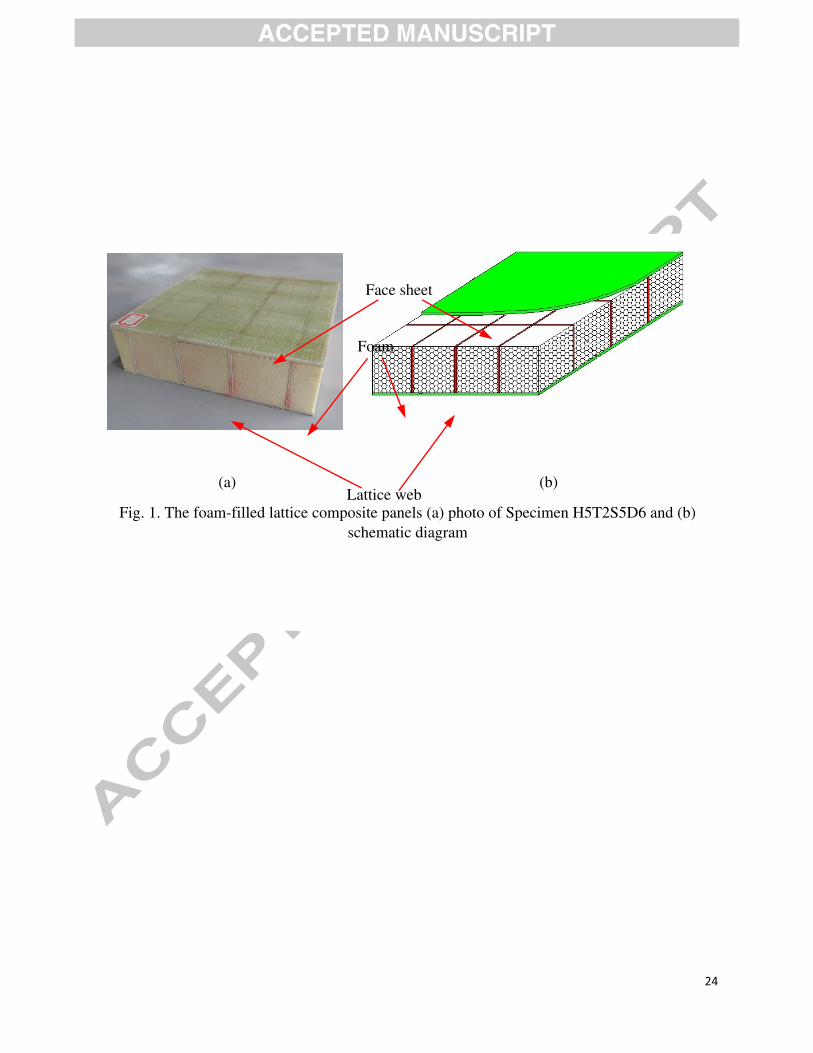
To address the aforementioned shortcoming, a simple and innovative foam-filled lattice
composite panel, manufactured through vacuum assisted resin infusion process [33], is
developed in this study, as shown in Fig. 1. The face sheets, lattice webs and foam cores are
combined by vacuum infusing resin, which can enhance the peel resistance between face sheets
and foam cores. Unlike other foam-core sandwich composite panels, the compressive strength of
foam is improved due to the confinement effects provided by lattice webs, and the foam cores
can also restrict the local buckling of the lattice webs. Hence, the compressive strength of foam-
filled lattice composite panels can be improved significantly. An experimental study was
conducted to validate the effectiveness of this new type of panel. The peak strength, initial
stiffness, deformability and energy absorbing capacity were investigated. A theoretical model
was also developed to predict the ultimate peak strength of panels.
2. Manufacture process
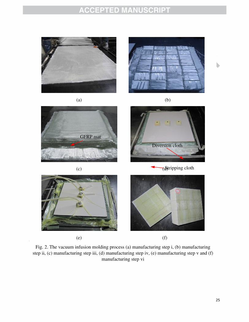
The manufacture process can be divided into the following six steps: (i) four GFRP mats are
placed on a large flat board as shown in Fig. 2(a), and the fiber orientation angle is 0/900 to the
panel horizontal axis; (ii) the foams are cut into cubes according to the design dimensions, and
then wrapped using GFRP with ±450 fiber orientation angle see Fig. 2(b); (iii) to place four
GFRP mats on the foam cores, and the fiber orientation angle is also 0/900 to the panel horizontal
axis; (iv) before vacuum infusing UPR, the stripping cloth, diversion cloth and a thicker cover
plate which is used to make the face board flat are installed, respectively, as shown in Fig. 2(d);
(v) the unsaturated polyester resin is infused into the vacuum bag due to the effect of
atmospheric pressure (see Fig. 2(e)); (vi) After UPR curing, the manufacture of foam-filled
lattice composite panels is completed, and then the panels are cut in accordance with special
requirements, as shown in Fig. 2(f).

6
3. Theoretical model
3.1. Local buckling of the GFRP web
The local buckling of the GFRP web can be analyzed using elastic foundation model, as
shown in Fig. 3(a). The foam is represented by the spring with a stiffness of k (per unit width and
length). In accordance with classical theory of elastic stability [34], the governing differential
equation for the stability analysis of web is expressed as
where D is the bending stiffness of the web, which can be determined by
where E and v are Young’s modulus and Poisson ratio of web, respectively.
The energy associated with the web deforming (U1) and the energy associated with the applied
loading (U2) are respectively given by
The loaded edges of web are fixed supports, and unloaded edges are simply supports. The
web is only subjected to a uniform axial compression in the x-direction. A half buckling wave
length in the x-direction is h, as shown in Fig. 3(b). By considering a half wave in the x-direction,
the boundary conditions of web at the loaded and unloaded edges are
when x = 0 or x = h, w = 0 and dw/dx = 0
when y = 0 or y = b, w = 0 and d2w/dx2 = 0

7
Assuming that the deflection functions in the x and y directions are the cosine and sine
functions, respectively, the deformed shape can be expressed as
The total potential energy of the GFRP web (E) is given as
where U3 is the energy associated with elastic foundation, defined as
According to the principle of minimum potential energy,
The critical buckling stress (fcr) can be calculated by
3.2. Ultimate axial load capacity
The panel can be considered as consisting of closed web-foam core (CWFC) element (Part I)
and unclosed web-foam core (UWFC) element (Part II), as shown in Fig. 3(c). For the CWFC
element, the depth and width are a and b, respectively. The thickness of web is t/2. By
considering force equilibrium, the theoretical peak strength of the CWFC element (Pc,pre) can be
expressed as
where AW and AF are cross-sectional areas of the web and foam, respectively, fW is the axial
compressive strength of web, and fF ’ is the axial compression strength of the confined foam,

8
which can be calculated by
where fF is the compressive strength of the unconfined foam, k1 is the effectiveness coefficient of
confinement, which is equal to 2.98 [35], fl is the lateral confining pressure, and ks is the shape
factor, which can be calculated by
where Ae is the effective confinement area, and RF is the corner radius.
Teng et al. [35] proposed the following formula to calculate the lateral confining pressure fl of
confined foam:
where fWt is the tension strength of web.
For the UWFC element, because the GFRP web can not provide the effective lateral confining
pressure to the foam, the effect of compressive strength of foam on the ultimate peak strength
can be ignored. Hence, the theoretical peak strength of the UWFC element (Pu,pre) can be
expressed as
If a local buckling failure occurs, the fW should be replaced by fcr in Eq. (15).
9
Then, the theoretical ultimate peak strength of panels (Ppre) can be expressed as
4. Experimental program
4.1. Test specimens
The specimens were manufactured using a vacuum assisted resin infusion process at Nanjing
University of Technology. The E-glass weave fabrics, referred to simply as GFRP, and HS-2101-
G100 unsaturated polyester resin (UPR) were used for face sheets and webs. The panels were
filled urethane foams (UF) with variation density (40 kg/m3, 60 kg/m3 and 80 kg/m3). During
vacuum infusion molding process, methyl ethyl ketone peroxide (MEKP) was used to be the
initiator of the unsaturated polyester resin.
In this study, 20 specimens were manufactured and tested. The specimen was cut from the
panels, and it was representative of a symmetric volume element of the structure when subjected
to compression loading, as shown in Fig. 1(a). All specimens had the same width (w=200 mm)
and length (d=200 mm). Specimens H5D4, H5D6, H7D6 and H5D8 were control specimens
without webs to demonstrate the mechanical performance of the normal foam core GFRP
sandwich panels. The other specimens were strengthened by webs with varying foam density (ρ),
thickness of the lattice web (t) and spacing of the lattice web (s). The details of specimens are
given in Table 1.
(1) Webs with either 50 mm, 75 mm or 100 mm height, designated as H5, H7 and H1,
respectively.
(2) Webs with either 2.4 mm, 4.8 mm or 7.2 mm thickness, designated as T2, T4 and T7,
respectively.

10
(3) Panels with either 50 mm, 75 mm or 100 mm web spacing, designated as S5, S7 and S1,
respectively.
(4) Foam density with either 40 kg/m3, 60 kg/m3 or 80 kg/m3, designated as D4, D6 and D8,
respectively.
4.2. Material properties
The urethane foams with different density (40 kg/m3、60 kg/m3 and 80 kg/m3) were used in
this study. For each density, five cubic foam samples of 50 mm thick were made and tested in
accordance with ASTM D1621-10 [36] to obtain the compressive strength and the Young’s
modulus. Table 2 shows the cube compressive strength and the Young’s modulus for each foam.
Tensile and compressive tests, based on ASTM D3039/D3039M-08 [37] and ASTM D695-10
[38] respectively, were carried out to determine the tensile strength, the tension Young’s
modulus, the compressive strength and the compression Young’s modulus of web. The material
tension and compression properties of web are summarized in Table 3.
4.3. Test set-up and Instrumentation
Fig. 4 shows the test set-up. The support system consisted of a steel framed structure. The base
of the frame was bolted to the strong floor of the Structural Engineering Laboratory at Nanjing
University of Technology. Loading was applied by a hydraulic actuator with an axial capacity of
500 kN. Prior to the compressive test, two surfaces of the specimen were connected to 20-mm-
thick steel plates, and the specimens were placed at the center of the loading system. The load
was applied under displacement control with a displacement rate at 0.015 mm/s.
Vertical loading data was collected via a five-channel load cell which was mounted directly
beneath the panels. Axial shortening was measured by four linear variable displacement

11
transducers (LVDTs) which were internal to the vertical actuator. The displacement data
reflected the total displacement of the top surface of the panel with respect to the bottom surface.
5. Test results and evaluation
5.1.Strength and Stiffness
The initial stiffness of a panel is defined as the slope of the load-displacement curve. The
initial stiffness K1 is given by Eq. (17)
where Py and Δy are yield load and corresponding yield displacement, respectively. According to
the load-displacement curves as shown in Figs. 5 to 7, it should be noted that the specimens
exhibited an approximate linear behavior until failure occurs, hence, the yield load (Py) could be
replaced by peak load (Pu) in Eq. (17).
The test results of all the specimens, including the peak strength (Pu), initial stiffness (K1),
stroke efficiency (Ste) and specific energy absorption (Se), are summarized in Table 4. Fig. 5 and
Fig. 8(a) show the effects of lattice web thickness on the Pu and K1 of panels. Compared to
Specimen H5D6 (Pu = 18.09 kN, K1 = 2.99 kN/mm), the Pu of Specimens H5T2S7D6,
H5T4S7D6 and H5T7S7D6 increased by 447.8%, 1317.3% and 2377.3%, respectively, and the
K1 of Specimens H5T2S7D6, H5T4S7D6 and H5T7S7D6 increased by 2051.8%, 4535.1% and
6416.4%, respectively. Compared to Specimen H7D6 (Pu = 20.15 kN, K1 = 4.01 kN/mm), the Pu
of Specimens H7T2S7D6, H7T4S7D6 and H7T7S7D6 increased by 698.9%, 1523.7% and
1581.3%, respectively, and the K1 of Specimens H5T2S7D6, H5T4S7D6 and H5T7S7D6
increased by 1375.8%, 3062.3% and 4700.2%, respectively. Compared to Specimen H5D4 (Pu =
4.66 kN) and H5D8 (Pu = 35.23 kN), the Pu of Specimens H5T2S5D4 and H5T2S5D8 increased
by 5314.4% and 807.2%, respectively. This may be due to the fact that thicker web can provide

12
higher lateral confining pressure to the foam as presented in Eq. (14), then the compressive
strength of the confined foam can be enhanced. Meanwhile, the thicker web can lead to a larger
axial stiffness. Hence, the use of thicker web can improve the strength and initial stiffness of
panels significantly.
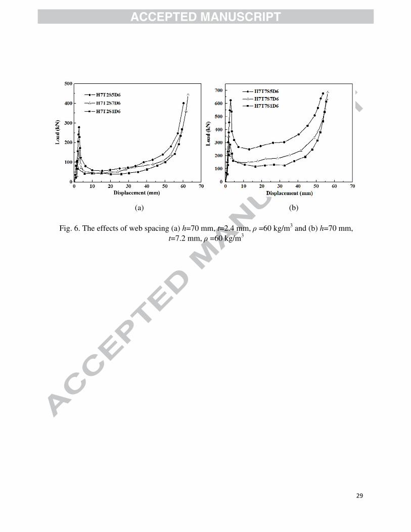
Fig. 6 and Fig. 8(b) illustrate the effects of lattice web spacing on the Pu and K1 of panels.
According to Fig. 6(a) and Fig. 8(b), for the specimens with 70mm web height, 2.4mm web
thickness and 60 kg/m3 foam density, the Pu and K1 of Specimen H7T2S5D6 (s = 50 mm) were
278.23 kN and 102.67 kN/mm, respectively, which were 72.8% and 1700.5% larger than the Pu
of Specimen H7T2S7D6 (s = 70 mm) and H7T2S1D6 (s = 100 mm), respectively, and 73.5%
and 84.4% larger than the K1 of Specimen H7T2S7D6 and H7T2S1D6, respectively. According
to Fig. 6(b) and Fig. 8(b), for the specimens with 70mm web height, 6.8mm web thickness and
60 kg/m3 foam density, the Pu and K1 of Specimen H7T7S5D6 (s = 50 mm) were 624.31 kN and
219.09 kN/mm, respectively, which were 84.3% and 118.6% larger than the Pu of Specimen
H7T7S7D6 (s = 70 mm) and H7T7S1D6 (s = 100 mm), respectively, and 13.8% and 91.8%
larger than the K1 of Specimen H7T2S7D6 and H7T2S1D6, respectively. According to Eq. (14),
the smaller web spacing can result in a larger lateral confining pressure to the foam, which can
improve the compressive strength of the confined foam. Therefore, decreasing the web spacing
can increase the peak strength of panels.
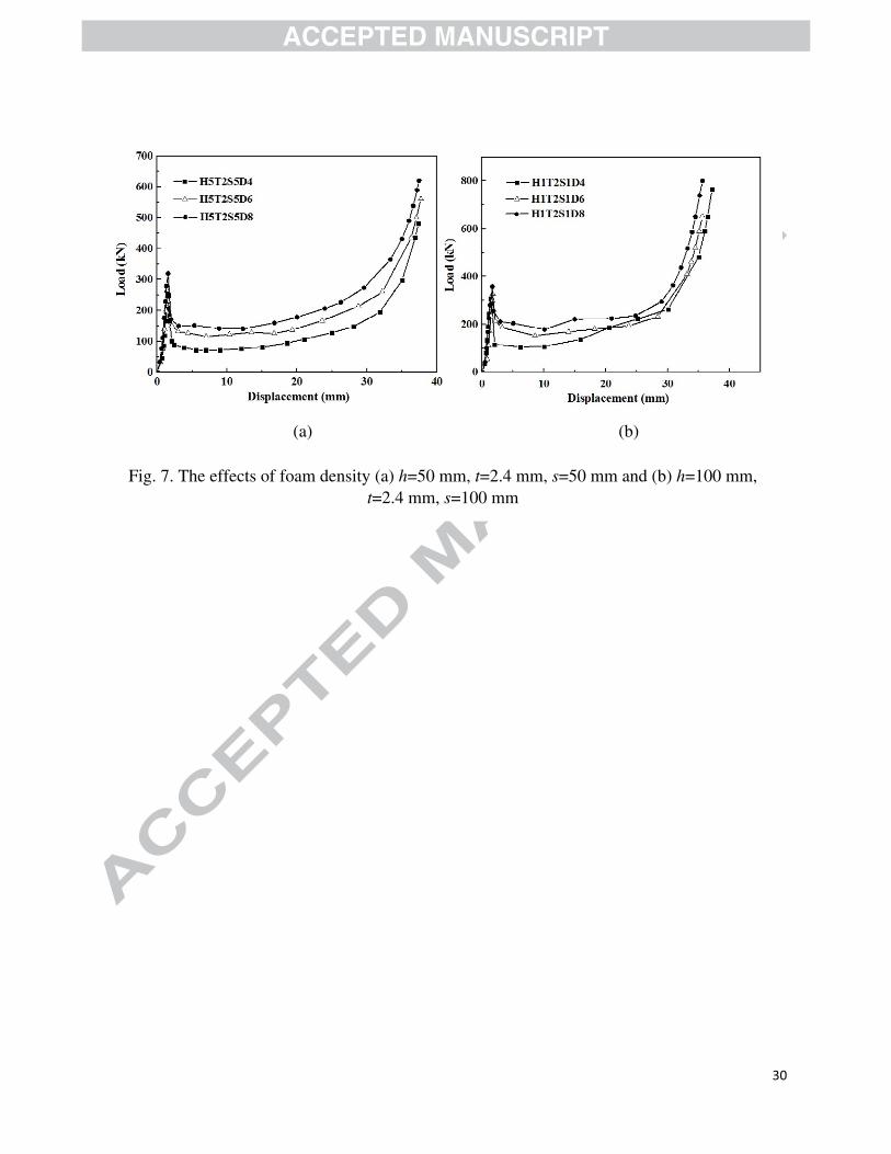
Fig. 7 and Fig. 8(c) illustrate the effects of foam density on the Pu and K1 of the panels.
Compared to Specimen H5T2S5D4 (Pu = 252.31 kN, K1 = 162.78 kN/mm), the Pu of Specimens
H5T2S5D6 and H5T2S5D8 increased by 5.1% and 26.7%, respectively, and the K1 of Specimens
H5T2S5D6 and H5T2S5D8 increased by 14.7% and 24.3%, respectively. Compared to
Specimen H1T2S1D4 (Pu = 308.10 kN, K1 = 174.07 kN/mm), the Pu of Specimens H1T2S1D6
and H1T2S1D8 increased by 6.4% and 15.9%, respectively, and the K1 of Specimens H1T2S1D6
13
and H1T2S1D8 increased by 8.2% and 22.1%, respectively. The foam with higher density also
behaves stiffer. Hence higher density foam can provide much more resistance to the applied
loads. Therefore, a larger foam density can give a higher peak strength and initial stiffness.
5.2. Compressive behavior and failure modes
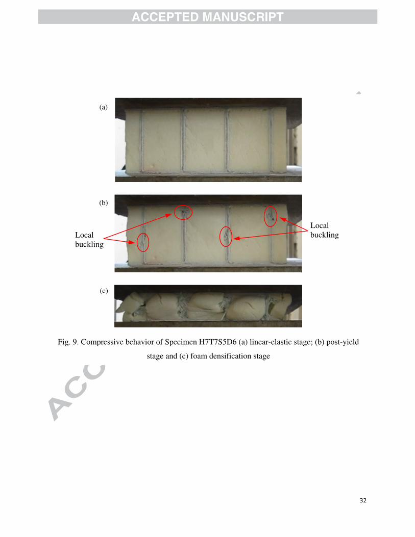
According to the load-displacement curves, the deformation of specimens can be divided into
three stages: linear-elastic stage, post-yield stage and foam densification stage. All specimens
exhibited a linear-elastic response up to failure at the elastic stage. In the post-yield stage, the
compressive load capacity decreased sharply, which was associated with buckling of lattice webs,
as shown in Fig. 9(b). The compressive load capacity of lattice composite panels roughly stayed
at a half of peak strength level, while the compressive load capacity of control specimens kept
peak load level. In the foam densification stage, the compressive load capacity of panels
increased, but the deformation of panels was very large. With an increasing applied load, the
buckled webs violently extruded the foam, which resulted in crushing of the foam, as shown in
Fig. 9(c).
For the sandwich members, there are usually five failure modes including face sheet
compressive/tensile failure, core shear failure, delamination, face sheet wrinkling and core
indentation failure. But all of them usually occurred in the bending tests. The core shear and
indentation failure usually occurred when the sandwich panels subjected to the concentrated
compression loading. In this study, the failure mode of all the specimens was quite similar.
However, the mentioned failure modes were not observed in this study because sandwich panels
were tested under uniform distributed axial compression loading. Due to the use of the GFRP
web, the failure modes can be categorized as two primary types: (1) GFRP web compressive
failure and (2) GFRP web local buckling failure. The microscopic phenomena which originate
14
the corresponding failure modes can be summarized, respectively, as follows: (1) the
compressive stress of the web reaches its yield stress before the occurance of the local buckling,
and (2) the critical buckling stress of the web is less than its yield stress. According to the critical
buckling stress obtained from Eq. (9), the failure mode of panels can be judged.
5.3. Stroke efficiency
The stroke efficiency (Ste) is introduced to evaluate the deformability of a panel. The load-
displacement responses of the specimens as shown in Figs.4-6 can be idealized as a quadri-linear
curve (Fig. 10). Because specimens exhibited an approximate linear response up to failure, a line
OA can be considered as a tangent line to the load-displacement curve before reaching the peak
strength. The line BC can be drawn according to the average value of the compressive strength in
the post-yield part. A tangent line CD to the load-displacement curve in the region of
densification of foam can be drawn and its intersection point with line BC is point C. The
horizontal coordinate value corresponding to point C is the stroke length (Δst). The stroke
efficiency [39] is defined as the ratio of the stroke length to the height of a panel (H), thus
Fig. 11(a) shows a distinct decrease of the measured stroke efficiencies with increasing web
thickness. The Ste of Specimens H5D6 and H7D6 (without web) were largest compared to the
corresponding lattice web composite panels. The Ste of Specimens H5T2S7D6 and H7T2S7D6
with 2.4 mm lattice web thickness reduced to 62.6% and 67.9%, respectively. The panels with
the thickest lattice webs had the lowest values of Ste (57.9% for H5T7S7D6, and 59.8% for
H7T7S7D6). The reason of this phenomenon was that the thicker webs can lead to the larger
axial stiffness of the panel, hence, the stroke length become small for a given compressive load.
15
Fig. 11(b) shows a slight increase of the measured stroke efficiencies with increasing lattice
web spacing. Compared to Specimen H7T2S5D6 (s = 50 mm), the Ste of Specimens H7T2S7D6
(s = 70 mm) and H7T2S1D6 (s = 100 mm) increased by 4.3% and 12.1%, respectively.
Compared to Specimen H7T7S5D6 (s = 50 mm), the Ste of Specimens H7T7S7D6 (s = 70 mm)
and H7T7S1D6 (s = 100 mm) increased by 6.9% and 14.9%, respectively. Because the larger
web spacing can give a smaller volume ratio of the web to the whole panel, hence the axial
stiffness of the panel decrease, which lead to an increase in the stroke length.
Fig. 11(c) shows a reduction of the measured stroke efficiencies with increasing foam density.
For Specimen H5T2S5D4 with 40 kg/m3 foam density, the measured stroke efficiency was
56.1%, while for Specimen H5T2S5D8, the Ste reduced to value of 44.7% due to the higher foam
density (ρ = 80 kg/m3). Although the difference in the web height and spacing, both curves in Fig.
10(c) show a similar trend. The Ste of Specimen H1T2S1D4 with 40 kg/m3 foam density was
28.0%, which was 12.4% and 15.1% larger than that of Specimen H1T2S1D6 (ρ = 60 kg/m3 )
and Specimen H1T2S1D6 (ρ = 60 kg/m3), respectively. Seitzberger et al. [39] proposed that the
reduction of the stroke efficiency is related to the foam behavior. With increasing foam density,
the region of densification, where the compressive force starts to increase steeply, was shifted to
lower values of the compressive strain. The foam suffered very large compressive strains and
prevented the deformation of the lattice webs, which reduced the stroke length of the panels.
5.4. Specific energy absorption
The specific energy absorption (Se) was adopted to evaluate the “mass efficiency” of a panel,
which is defined as [39]

16
where m is the total mass of a panel, and W is the total energy, which is given by Eq. (20)
where P is the applied compressive force, and Δ is the displacement of specimen (with
integration variable ). Assuming that the contribution due to elastic deformations is negligible,
W can approximately be regarded as the energy dissipated by plastic deformation.
Fig. 12(a) shows the effects of lattice web thickness on the specific energy absorption of the
panels. For the specimens with 70 mm web height, 70 mm web spacing and 60 kg/m3 foam
density, the Se of Specimen H7T7S7D6 (t = 7.2 mm) was 4.3, which was 207.1%, 30.3% and
10.3% larger than that of Specimen H7D6 (without lattice webs), H7T2S7D6 (t = 2.4 mm) and
H7T4S7D6 (t = 4.8 mm), respectively. For the specimens with 50 mm web height, 70 mm web
spacing and 60 kg/m3 foam density, the Se of Specimen H5T7S7D6 (t = 7.2 mm) was 4.1, which
was 485.7%, 141.2% and 17.1% larger than the Se of Specimen H5D6 (without lattice webs),
H5T2S7D6 (t = 2.4 mm) and H5T4S7D6 (t = 4.8 mm), respectively. Hence, the lattice web
thickness can play an important role in increasing the energy absorption of the panels.
Fig. 12(b) shows the effects of lattice web spacing on the specific energy absorption of the
panels. For the specimens with 70 mm web height, 2.4 mm web thickness and 60 kg/m3 foam
density, the Se of Specimen H7T2S5D6 (s = 50 mm) was largest, which was equal to 3.9, the Se
of Specimens H7T2S7D6 (s = 70 mm) and H7T2S1D6 (s = 100 mm) were 3.3 and 2.4,
respectively. For the specimens with 70 mm web height, 7.2 mm web thickness and 60 kg/m3
foam density, the Se of Specimen H7T7S5D6 (s = 50 mm) was largest, which was equal to 5.2,
the Se of Specimens H7T7S7D6 (s = 70 mm) and H7T7S1D6 (s = 100 mm) were 4.3 and 3.6,
respectively. The test results indicated that the smaller lattice web spacing of the panels can
achieve the larger energy absorption.
17
Fig. 12(c) shows the effects of foam density on the specific energy absorption of the panels.
For the specimens with 50 mm web height, 2.4 mm web thickness and 50 mm web spacing, the
Se of Specimen H5T2S5D4 (ρ = 40 kg/m3) was 2.6, which was 19.2% and 34.6% smaller than
that of Specimen H5T2S5D6 (ρ = 60 kg/m3) and H5T2S5D8 (ρ = 80 kg/m3), respectively. For
the specimens with 100 mm web height, 2.4 mm web thickness and 100 mm web spacing, the Se
of Specimen H1T2S1D4 (ρ = 40 kg/m3) was 3.7, which was 8.1% and 18.9% smaller than that of
Specimen H1T2S1D6 (ρ = 60 kg/m3) and H1T2S1D8 (ρ = 80 kg/m3), respectively. Thus, the
energy absorption of the panels can be enhanced using the foam with the higher density.
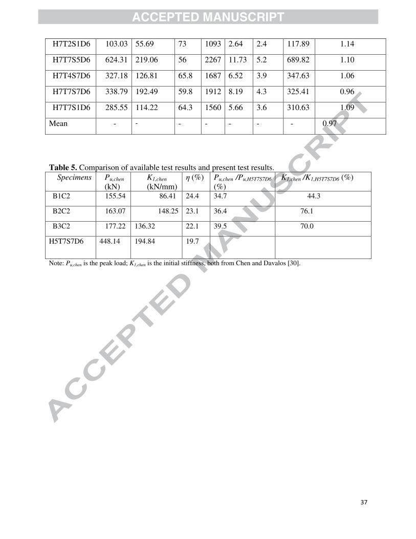
6. Comparison with available experimental results
Chen and Davalos [30] tested three FRP sandwich deck panels with sinusoidal core geometry
under compression loading. The face sheets and cores consisted of chopped strand mat. For each
specimen, the volume ratio of the core respect to the whole panel (η) was calculated. Table 5
compares the peak strength and initial stiffness presented in Chen and Davalos [30] with those of
Specimen H5T7S7D6 because the value of η of Specimen H5T7S7D6 is similar with their
specimens. Compared to Specimen H5T7S7D6, the Pu of Specimens B1C2, B2C2 and B3C2
decrease to 34.7%, 36.4% and 39.5%, respectively, meanwhile, the K1 of Specimens B1C2,
B2C2 and B3C2 decrease to 44.3%, 76.1% and 70.0%, respectively. The reason is that for the
specimen H5T7S7D6, the critical buckling stress of web can be increased due to the restriction
from foam cores, and the compressive strength of the foam is also improved because of the
confinement provided by webs. Hence, even the value of η of Specimen H5T7S7D6 is slightly
smaller, larger peak strength and initial stiffness can be achieved.
7. Comparison with available experimental results
18
Table 4 summarized the theoretical ultimate peak strength of panels. During the calculation,
Specimens H5T2S5D4, H5T2S5D6, H5T2S5D8 and H7T2S5D6 failed by local buckling of web.
The critical buckling stresses of them were 36 MPa, 40 MPa, 54 MPa and 51 MPa, respectively.
For the foam-filled lattice composite panels, the largest variation between theoretical and
experimental results in the ultimate peak strength was 18%, which occurred in Specimen
H5T2S5D8. In general, comparing the theoretical and experimental ultimate peak strengths
reveals that the proposed theoretical model is able to conservatively estimate the actual ultimate
peak strength of panels under quasi-static compression loading with an average underestimation
of 3%.
8. Conclusions
This paper presents an experimental investigation on the foam-filled lattice composite panels
under quasi-static axial compression loading. The main findings of this study are summarized as
follows:
(1) A kind of foam-filled lattice composite panels applied to civil engineering field was
developed through vacuum assisted resin infusion process. The comparison between the
available test results of Chen and Davalos [30] and the test results was presented. These
panels had the characteristics of high compressive stiffness and strength, and strong energy
absorbing capacity.
(2) The experimental results show that compared to the foam-filled composite panels, a
maximum of an approximately 1600% increase in the peak load of panels can be achieved
due to the use of lattice webs.
(3) The thicker lattice web and smaller lattice web spacing can enhance the peak load of panels
significantly, but the effects of foam density on the peak load of panels are small.

19
(4) A quadri-linear curve was proposed to idealize the load-displacement responses of panels.
The stroke length can be determined according to the quadri-linear curve.
(5) The thiner lattice web and larger lattice web spacing can the improve stroke efficiency of
panels, while the larger foam density can decrease the stroke efficiency of panels because the
larger density foam, suffered larger compressive strain, can provide much more resistance to
prevent the folds from touching each other.
(6) The energy absorption of panels is affected by lattice web thickness, lattice web spacing and
foam density. Larger energy absorption can be achieved by increasing the lattice web
thickness and foam density and decreasing the web spacing.
(7) Overall, it has been demonstrated that the foam-filled lattice composite panels exhibited
better performance than the normal foam-core sandwich panels. It is expected that the foam-
filled lattice composite panels can be widely used as bridge decks, formworks and wall
boards.
Acknowledgements
The research described here was supported by the Key Program of National Natural Science
Foundation of China (Grant No. 51238003), Natural Natural Science Foundation for the Youth
(Grant No. 51008157) and Key University Science Research Project of Jiangsu Province (Grant
No. 12KJA580002).
References
20
[1]. Ugale1 VB, Singh KK, Mishra NM and Kumar P, Experimental studies on thin sandwich
panels under impact and static loading. Journal of Reinforced Plastics and Composites 2012;
32(6): 420-434.
[2]. Tagarielli VL, Dashpande VS, Fleck NA, Chen C. A constitutive model for transversely
isotropic foams, and its application to the indentation of balsa woods. International Journal of
Mechanical Sciences 2005;47(1): 666–86.
[3]. Silva AD, Kyriakides S. Compressive response and failure of balsa wood. International
Journal of Solid and Structures 2007;44(25-26):8685–717.
[4]. Vural M, Ravichandran G. Dynamic response and energy dissipation characteristics of balsa
wood: experiment and analysis. International Journal of Solids and Structures 2003;40(9):2147–
70.
[5]. Grenestedt KL, Bekisli B. Analyses and preliminary tests of balsa sandwich core with
improved shear properties. International Journal of Mechanical Sciences 2003;45(8):1327–46.
[6]. Osei-Antwi M, Castro J, Vassilopoulos AP, et al. Shear mechanical characterization of balsa
wood as core material of composite sandwich panels. Construction and Building Materials 2013;
41: 231–238.
[7]. Bekisli B, Grenestedt JL. Experimental evaluation of a balsa sandwich core with improved
shear properties. Composites Science and Technology 2004; 64(5): 667-674.
[8]. Yu TX, Tao XM, Xue P. The energy-absorbing capacity of grid-domed textile composites.
Composites Science and Technology 2000; 60(5): 785–800.
[9]. Lam SW, Tao XM, Yu TX. Comparison of different thermoplastic cellular textile
composites on their energy absorption capacity. Composites Science and Technology 2004;
64(13-14): 2177–2184.
[10] Flores-Johnson EA, Li QM. Experimental study of the indentation of sandwich panels with
carbon fibre-reinforced polymer face sheets and polymeric foam core. Composites, Part B:
Engineering 2011; 42: 1212–1219.
21
[11] Roberts JC, Boyle MP, Wienhold PD, White GJ. Buckling, collapse and failure analysis of
FRP sandwich panels. Composites, Part B: Engineering 2002; 33: 315–324.
[12]. Tekalur SA, Bogdanovich AE, Shukla A. Shock loading response of sandwich panels with
3-D woven E-glass composite skins and stitched foam core. Composites Science and Technology
2009; 69(6): 736–753.
[13] Less H, Abramovich H. Dynamic buckling of a laminated composite stringer-stiffened
cylindrical panel. Composites, Part B: Engineering 2012; 43: 2348–2358.
[14] Du Y, Yan N, Kortschot MT. Light-weight honeycomb core sandwich panels containing
biofiber-reinforced thermoset polymer composite skins: Fabrication and evaluation. Composites,
Part B: Engineering 2012; 43: 2875–2882.
[15] Sadighi M, Hosseini SA. Finite element simulation and experimental study on mechanical
behaviour of 3D woven glass fiber composite sandwich panels. Composites, Part B: Engineering
2013; 55: 158–166.
[16] Rejab MRM, Cantwell WJ. The mechanical behaviour of corrugated-core sandwich panels.
Composites, Part B: Engineering 2013; 47: 267–277.
[17]. Wang J, Waas AM, Wang H. Experimental and numerical study on the low-velocity impact
behaviour of foam-core sandwich panels. Composite Structures 2013; 96: 298–311.
[18]. Found MS, Robinson AM, Carruthers JJ. The influence of FRP inserts on the energy
absorption of a foam-cored sandwich panel. Composite Structures 1997; 38(4): 373–381.
[19]. Altenbach H. An alternative determination of transverse shear stiffnesses for sandwich and
laminated plates. International Journal of Solids and Structures 2000; 37: 3503–3520.
[20]. Koissin V, Shipsha A, Skvortsov V. Compression strength of sandwich panels with sub-
interface damage in the foam core. Composites Science and Technology 2009; 69(13): 2231–
2240.
[21]. Idris MI, Vodenitcharova T, Hoffman M. Mechanical behaviour and energy absorption of
22
closed-cell aluminium foam panels in uniaxial compression. Materials Science and Engineering
A 2009; 517(1-2): 37–45.
[22]. Cartié DD, Fleck NA. The effect of pin reinforcement upon the through-thickness
compressive strength of foam-cored sandwich panels. Composites Science and Technology 2003;
63(16): 2401–2409.
[23]. Fan H, Yang W, Zhou Q. Experimental research of compressive responses of multi-layered
woven textile sandwich panels under quasi-static loading. Composites: Part B 2011; 42(5):
1151–1156.
[24]. Fan H, Zhou Q, Yang W, et al. An experiment study on the failure mechanisms of woven
textile sandwich panels under quasi-static loading. Composites: Part B 2010; 41(8): 686–692.
[25]. Deshpande VS, Fleck NA. Energy absorption of an egg-box material. Journal of the
Mechanics And Physics Of Solids 2003;51(1):187–208.
[26]. Zupan M, Chen C, Fleck NA. The plastic collapse and energy absorption capacity of egg-
box panels. International Journal of Mechanical Sciences 2003;45(5):851–871.
[27]. Chung JG, Chang SH, Sutcliffe MPF. Deformation and energy absorption of composite
egg-box panels. Composites Science and Technology 2007;67(11-12):2342–2349.
[28]. Yoo SH, Chang SH, Sutcliffe MPF. Compressive characteristics of foam-filled composite
egg-box sandwich panels as energy absorbing structures. Composites: Part A 2010; 41(3): 427–
434.
[29]. Choy YS, Lau KT, Wang C, Chau CW, Liu Y, Hui D. Composite panels for reducing noise
in air conditioning and ventilation systems. Composites: Part B 2009; 40(4): 259–266.
[30]. Chen A, Davalos JF. Strength evaluations of sinusoidal core for FRP sandwich bridge deck
panels. Composite Structures 2010; 92: 1561–1573.

23
[31]. Davalos JF, Chen A. Buckling behaviour of honeycomb FRP core with partially restrained
loaded edges under out-of-plane compression. Journal of Composite Materials 2005; 39(16):
1465–85.
[32]. Chen A, Davalos JF. Transverse shear with skin effect for composite sandwich with
honeycomb sinusoidal core. Journal of Engineering Mechanics-ASCE 2007;133(3):247–56.
[33]. Poodts E, Minak G, Dolcini E, Donati L. FE analysis and production experience of a
sandwich structure component manufactured by means of vacuum assisted resin infusion process.
Composites, Part B: Engineering 2013; 53: 179–186.
[34]. Timoshenko SP, Gere JM. Theory of elastic stability. 2nd ed. New York: McGraw-Hill;
1961.
[35]. Teng JG, Chen JF, Smith ST, Lam L. FRP-strengthened RC structures. Chichester: Wiley;
2002.
[36]. ASTM D1621-10. Standard Test Method for Compressive Properties of Rigid Cellular
Plastics, ASTM, PA, USA; 2010.
[37]. ASTM D3039/D3039M-08. Standard test method for tensile properties of polymer matrix
composite materials, ASTM, PA, USA; 2008.
[38]. ASTM D695-10. Standard test method for compressive properties of rigid plastics, ASTM,
PA, USA; 2010.
[39]. Seitzberger M, Rammerstorfer FG, Gradinger R, Degischer HP, Blaimschein M, Walch C.
Experimental studies on the quasi-static axial crushing of steel columns filled with aluminum
foam. International Journal of Solids and Structures 2000; 37(30): 4125–4147.
24
(a) (b)
Fig. 1. The foam-filled lattice composite panels (a) photo of Specimen H5T2S5D6 and (b) schematic diagram
Face sheet
Foam
Lattice web
25
(a) (b)
(c) (d)
(e) (f)
Fig. 2. The vacuum infusion molding process (a) manufacturing step i, (b) manufacturing step ii, (c) manufacturing step iii, (d) manufacturing step iv, (e) manufacturing step v and (f)
manufacturing step vi
Stripping cloth
Diversion cloth
GFRP mat

26
(a) (b) (c)
Fig. 3. Theoretical model (a) elastic foundation model; (b) local buckling calculation and (c) closed
web-foam core element (Part I) and unclosed web-foam core element (Part II)
GFRP Web
a
b

27
Fig. 4. Test set-up
Specimen
Load cell

28
(a) (b)
(c) (d)
Fig. 5. The effects of lattice web thickness (a) h=50 mm, s=70 mm, ρ=60 kg/m3; (b) h=70 mm, s=70 mm, ρ =60 kg/m3; (c) h=50 mm, s=50 mm, D=40 kg/m3 and (d) h=50 mm, s=50
mm, ρ =80 kg/m3
29
(a) (b)
Fig. 6. The effects of web spacing (a) h=70 mm, t=2.4 mm, ρ =60 kg/m3 and (b) h=70 mm, t=7.2 mm, ρ =60 kg/m3
30
(a) (b)
Fig. 7. The effects of foam density (a) h=50 mm, t=2.4 mm, s=50 mm and (b) h=100 mm, t=2.4 mm, s=100 mm

31
(a) (b)
(c) Fig. 8. The initial stiffness of the panels (a) the effects of lattice web thickness; (b) the effects
of lattice web spacing and (c) the effects of the foam density
32
Fig. 9. Compressive behavior of Specimen H7T7S5D6 (a) linear-elastic stage; (b) post-yield
stage and (c) foam densification stage
(a)
(b)
(c)
Local buckling Local
buckling

33
Fig. 10. The idealized load-displacement curve
(a) (b)
(c)
Fig. 11. The stroke efficiency of the panels (a) the effects of lattice web thickness; (b) the effects of lattice web spacing and (c) the effects of foam density
Quatri-linear approx.
Actural Behavior
A
B C
D

34
(a) (b)
(c) Fig. 12. The specific energy absorption of the panels (a) the effects of lattice web thickness;
(b) the effects of lattice web spacing and (c) the effects of foam density

35
Table 1. Details of specimens.
Specimen H
(mm)
s
(mm)
h
(mm)
t (mm)
ρ (kg/m3)
H5D4 54.8 - 50 - 40
H5D6 54.8 - 50 - 60
H7D6 74.8 - 70 - 60
H5D8 54.8 - 50 - 80
H5T2S5D4 54.8 50 50 2.4 40
H5T2S5D6 54.8 50 50 2.4 60
H5T2S5D8 54.8 50 50 2.4 80
H5T2S7D6 54.8 75 50 2.4 60
H5T4S7D6 54.8 75 50 4.8 80
H5T7S7D6 54.8 75 50 7.2 80
H1T2S1D4 104.8 100 100 2.4 40
H1T2S1D6 104.8 100 100 2.4 60
H1T2S1D8 104.8 100 100 2.4 80
H7T2S5D6 74.8 50 70 2.4 60
H7T2S7D6 74.8 75 70 2.4 60
H7T2S1D6 74.8 100 70 2.4 60
H7T7S5D6 74.8 50 70 7.2 60
H7T4S7D6 74.8 75 70 4.8 60
H7T7S7D6 74.8 75 70 7.2 60
H7T7S1D6 74.8 100 70 7.2 60

36
Table 2. Material properties of Foams. Foam density D
(kg/m3) Yield strength ffy
(MPa) Young’s modulus Ef (MPa)
40 0.163 4.83
60 0.358 9.38
80 0.609 14.70
Table 3. Material properties of lattice webs. Compression Yield strength fcy (MPa) Young’s modulus Ec (GPa) 59.76 5.66
Tension Yield strength fty (MPa) Young’s modulus Et (GPa) 296.31 6.41
Table 4. Experimental and theoretical results of specimens. Specimen Pu (kN) K1
(kN/mm)
Ste
(%)m
( g )W(Δst)
(kJ)Se
(kJ/kg)Ppre
(kN)
Ppre / Pu
H5D4 4.66 1.86 68.5 771 0.13 0.2 6.52 1.40
H5D6 18.09 2.99 67.2 811 0.57 0.7 14.32 0.79
H7D6 20.15 4.01 73.5 859 1.23 1.4 14.32 0.71
H5D8 35.23 7.03 64.3 851 1.07 1.3 24.36 0.69
H5T2S5D4 252.31 162.78 56.1 1109 2.88 2.6 229.84 0.91
H5T2S5D6 265.11 186.7 49.3 1147 3.55 3.1 240.33 0.91
H5T2S5D8 319.61 202.28 44.7 1191 4.16 3.5 261.10 0.82
H5T2S7D6 99.09 64.34 62.6 1062 1.77 1.7 113.65 1.15
H5T4S7D6 56.39 138.59 60.2 1312 4.58 3.5 284.33 1.11
H5T7S7D6 448.14 194.84 57.9 1563 6.34 4.1 489.69 1.09
H1T2S1D4 308.1 174.07 28 1109 4.12 3.7 260.34 0.84
H1T2S1D6 27.84 188.41 24.9 1134 4.55 4.0 272.36 0.83
H1T2S1D8 357.13 212.58 24.3 1195 5.29 4.4 299.32 0.84
H7T2S5D6 278.23 102.67 65.1 1327 5.15 3.9 230.97 0.83
H7T2S7D6 160.97 59.18 67.9 1102 3.65 3.3 175.56 1.09
37
H7T2S1D6 103.03 55.69 73 1093 2.64 2.4 117.89 1.14
H7T7S5D6 624.31 219.06 56 2267 11.73 5.2 689.82 1.10
H7T4S7D6 327.18 126.81 65.8 1687 6.52 3.9 347.63 1.06
H7T7S7D6 338.79 192.49 59.8 1912 8.19 4.3 325.41 0.96
H7T7S1D6 285.55 114.22 64.3 1560 5.66 3.6 310.63 1.09
Mean - - - - - - - 0.97
Table 5. Comparison of available test results and present test results.
Specimens Pu,chen
(kN) K1,chen
(kN/mm) η (%) Pu,chen /Pu,H5T7S7D6
(%) K1,chen /K1,H5T7S7D6 (%)
B1C2 155.54 86.41 24.4 34.7 44.3
B2C2 163.07 148.25 23.1 36.4 76.1
B3C2 177.22 136.32 22.1 39.5 70.0
H5T7S7D6 448.14 194.84 19.7
Note: Pu,chen is the peak load; K1,chen is the initial stiffness, both from Chen and Davalos [30].