themis mission cdr 1 ucb, june 17, 2004 magnetometer booms critical design review dr. hari dharan...
TRANSCRIPT
THEMIS Mission CDR 1 UCB, June 17, 2004
Magnetometer BoomsCritical Design Review
Dr. Hari Dharan
Berkeley Composites Laboratory
Department of Mechanical Engineering
University of California at Berkeley

THEMIS Mission CDR 2 UCB, June 17, 2004
Overview
Magnetometer Booms• System Overview
• Technical Requirements
• System Mechanical Design
• Updates to Analyses
• Design Margins
• Mass and Power
• Test Plan
• Fabrication Plan
• Integration Plan
• Performance Assurance
• Schedule
• Parts and Materials Status
• Contamination Control
• Problem Areas

THEMIS Mission CDR 3 UCB, June 17, 2004
System Overview
Magnetometer Booms• Each probe has two magnetometers – Flux Gate
Magnetometer (FGM) and Search Coil Magnetometer (SCM).
• The magnetometers are to be magnetically isolated by suspending via booms from probe.
• The booms must be stowed to fit the envelope of the probe.
• 1.25 in. ID carbon-fiber tubes.
• Al hinges and brackets.
• FGM is deployed 2.25m from S/C center.
• SCM is deployed 1.4m from S/C center

THEMIS Mission CDR 4 UCB, June 17, 2004
System Overview
SCMSearch Coil
Magnetometer
FGMFlux Gate
Magnetometer
FGM Base Hinge: Saloon Door Mechanism and Frangibolt Actuator
SCM Frangibolt Tower
FGM Elbow Hinge / Deploy Assist Device (DAD)
SCM Base Hinge, similar to FGM Base Hinge, with no Frangibolt
Carbon Fiber Tubes
S/C Top Deck
Saloon Door Spring
Deployment Assist Spring
Frangibolt
THEMIS Mission CDR 5 UCB, June 17, 2004
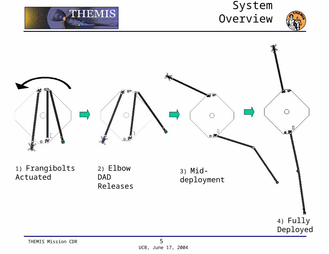
System Overview
1) Frangibolts Actuated
3) Mid-deployment2) Elbow DAD Releases
4) Fully Deployed

THEMIS Mission CDR 6 UCB, June 17, 2004
REQUIREMENT BOOM DESIGN
IN-7. No component of the Instrument Payload shall exceed the allocated mass budget in THM-SYS-008 THEMIS System Mass Budget.xls
Compliant.
FGM Boom: 0.97kg Allocated.
SCM Boom: 0.65kg Allocated.
IN-9. No component of the Instrument Payload shall exceed the power allocated in THM-SYS-009 THEMIS System Power Budget.xls
Compliant.
Frangibolt: ~25W transient
IN-13. The Instrument Payload shall survive the temperature ranges provided in the ICDs
Compliant.
IN-14. The Instrument Payload shall perform as designed within the temperature ranges provided in the ICDs
Compliant.
IN-16 The Instrument Payload shall comply with the Magnetics Cleanliness standard described in the THEMIS Magnetics Control Plan
Compliant. THM-SYS-002 Magnetics Control Plan.
IN-17 The Instrument Payload shall comply with the THEMIS Electrostatic Cleanliness Plan
Compliant. THM-SYS-003 Electrostatic Cleanliness Plan
IN-18 The Instrument Payload shall comply with the THEMIS Contamination Control Plan
Compliant. THM-SYS-004 Contamination Control Plan
Mission Requirements

THEMIS Mission CDR 7 UCB, June 17, 2004
REQUIREMENT BOOM DESIGN
IN-21. The Instrument Payload shall be compatible per the IDPU-Probe Bus ICD
Compliant. THM-SYS-112 Probe-to-FGM Mag Boom ICD. THM-SYS-113 Probe-to-SCM Mag Boom ICD..
IN-23 The Instrument Payload shall verify performance requirements are met per the THEMIS Verification Plan and Environmental Test Spec.
Compliant. THM-SYS-005 Verification Plan and Environmental Test Specification preliminary draft.
IN-24 The Instrument Payload shall survive and function prior, during and after exposure to the environments described in the THEMIS Verification Plan and Environmental Test Specification
Compliant. THM-SYS-005 Verification Plan and Environmental Test Specification preliminary draft.
Mission Requirements

THEMIS Mission CDR 8 UCB, June 17, 2004
REQUIREMENT BOOM DESIGN
IN.BOOM-1. Mag Boom deployment shall be repeatable to 1 degree
Compliant.
IN.BOOM-2. Mag Boom stability shall be better than 0.1 degree (includes bus and boom components)
Compliant.
IN.BOOM-3. Mag Boom deployed stiffness shall be greater than 0.75Hz
Compliant.
IN.BOOM-4. Mag Boom shall be designed to be deployed between 2 and 15 RPM about the Probe's positive Z axis.
Compliant.
IN.BOOM-8. The FGM boom shall be approximately 2 meters long.
Compliant.
IN.BOOM-9. The SCM boom shall be approximately 1 meters long.
Compliant.
IN.BOOM-12. All deployed booms shall include an inhibit to prevent inadvertent release.
Compliant.
Boom Requirements
THEMIS Mission CDR 9 UCB, June 17, 2004
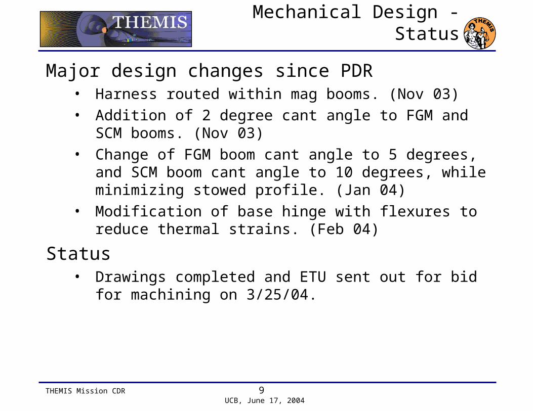
Mechanical Design - Status
Major design changes since PDR• Harness routed within mag booms. (Nov 03)
• Addition of 2 degree cant angle to FGM and SCM booms. (Nov 03)
• Change of FGM boom cant angle to 5 degrees, and SCM boom cant angle to 10 degrees, while minimizing stowed profile. (Jan 04)
• Modification of base hinge with flexures to reduce thermal strains. (Feb 04)
Status• Drawings completed and ETU sent out for bid for machining
on 3/25/04.

THEMIS Mission CDR 10 UCB, June 17, 2004
System Mechanical Design
Frangibolts
• Frangibolt actuation separates stowed booms from S/C.
• TiNi Aerospace’s FC2-16-31SR2.
• Reliable.
• Low mass & power requirements.
Load supported 2200N
Mass 20g
Power 25W
Operating Temp. -65°C - +80°C

THEMIS Mission CDR 11 UCB, June 17, 2004
System Mechanical Design
Frangibolt Implementation
V-Shaped Interface:• Isolates the Frangibolt from vibration loads
– vertical shear and moments
• Allows axial compliance for assembly
Frangibolt Cover:• Contains Frangibolt after firing
– Shields components per NASA LLS 1360

THEMIS Mission CDR 12 UCB, June 17, 2004
System Mechanical DesignElbow Latch
Deployment Assist Spring
Location
Harness Tie-Down Clip
Harness Routing Spool
Hook-Pin Latch Device
Flexure Feet
Kickoff Disk Springs

THEMIS Mission CDR 13 UCB, June 17, 2004
System Mechanical DesignBase Hinge Design Features
Deployment Assist Spring
Frangibolt(Integrated Shear Support)
Latch Pin
Flexure Mount Feet
“Saloon Door” Spring

THEMIS Mission CDR 14 UCB, June 17, 2004
System Mechanical Design
Base Hinge, Animated
THEMIS Mission CDR 15 UCB, June 17, 2004
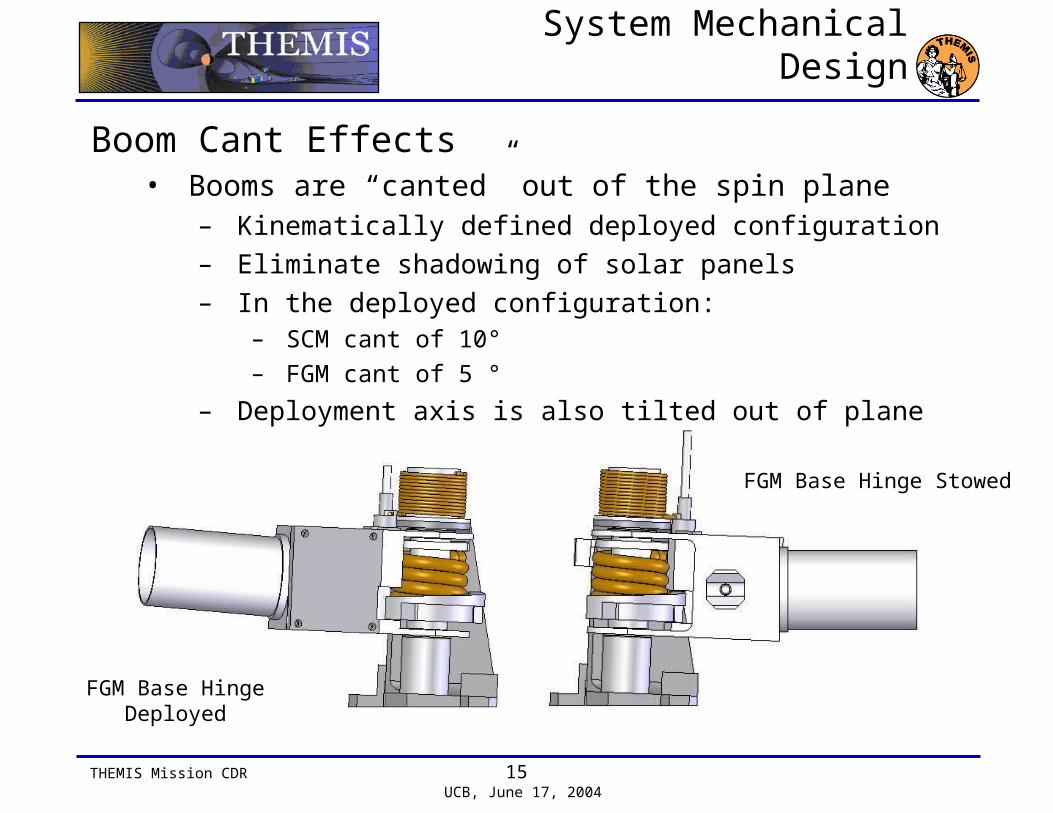
System Mechanical Design
Boom Cant Effects• Booms are “canted” out of the spin plane
– Kinematically defined deployed configuration– Eliminate shadowing of solar panels– In the deployed configuration:
– SCM cant of 10°
– FGM cant of 5 °
– Deployment axis is also tilted out of plane
FGM Base Hinge Deployed
FGM Base Hinge Stowed

THEMIS Mission CDR 16 UCB, June 17, 2004
System Mechanical Design
Tube Lay-up• [(±45)T300 / 0M55J,4 ]s
– T300 = high-strength carbon fiber woven composite (0.005”/ply), M55J = high-modulus carbon fiber unidirectional composite tape (0.0025”/ply)
– Matrix = YLA RS3 cyanate ester.
• Thickness = 0.03 in.
• Inside diameter = 1.25 in.
• Effective longitudinal modulus = 30.9 x 10⁶ psi (213 GPa)
• Mass per unit length = 3.2 g/in (1.26 g/cm)

THEMIS Mission CDR 17 UCB, June 17, 2004
Dynamic Analysis Update
Dynamic Model Overview• Numerical solution of Kinematics & Rigid Body Dynamics
• Includes:– Kickoff spring forces– Deployment assist spring moments– Latching and de-latching events
• Updated for– Boom cant effects– Frictional torque
THEMIS Mission CDR 18 UCB, June 17, 2004
Dynamic Analysis Update
Assumptions:• Increase in moment of inertia due to booms deploying will
not slow the spacecraft enough to effect deployment use a constant spacecraft spin rate to simplify analysis
• Linear springs
• Elastic collisions (conservative assumption)
• Constant frictional torques
• Booms are rigid links
• Deployment is in-plane

THEMIS Mission CDR 19 UCB, June 17, 2004
Dynamic Analysis Update
MATLAB Simulation• Inputs
– Satellite spin rates– Initial boom positions– Boom lengths, MOIs, spring constants, values of friction,
etc…– Latching locations
• Outputs– Deployment animation– Hinge Forces and Moments– Deployment time

THEMIS Mission CDR 20 UCB, June 17, 2004
Dynamic Analysis Update
Boom Cant Effects• Effects due to tilt of deployment axis
– Strategy: Plug simulated 2-D values for αz and ωz (which also generates small values of αY and ωY into full 3-D moment equation, observe deviation from 2-D results
– Error in predicted αz values ~0.12%
– Addition of out-of-plane moments MX and MY
– These are nontrivial, producing frictional moments on the same order as sum of all other moments considered
– Moments only act during high velocity or acceleration, i.e. during latching positive effect
– 2-D Moment Equation:– Full 3-D Moment Equation
z
y
x
zzyzxz
yzyyxy
xzxyxx
xy
xz
yz
z
y
x
zzyzxz
yzyyxy
xzxyxx
z
y
x
III
III
III
III
III
III
M
M
M
0
0
0
zzzz IM

THEMIS Mission CDR 21 UCB, June 17, 2004
Deployment Stress Analysis
Stress/FEM• Latching loads from dynamic analysis
• FEM models for hinge analysis– FOS = 1.7 (SCM @ 15rpm)

THEMIS Mission CDR 22 UCB, June 17, 2004
Torque Margin Analysis
Sources of friction considered• Latch pin sliding along ramp : Vespel-3 on aluminum
• Clevis on hinge pin: 544 bronze on 303 stainless – Applies for base hinge and elbow– Forces due to 1) deployment spring force reacting through
hinge and 2) out-of-plane moment due to boom canting

THEMIS Mission CDR 23 UCB, June 17, 2004
Torque Margin Analysis

THEMIS Mission CDR 24 UCB, June 17, 2004
Thermal Analysis Updates
Tube bending with thermal gradient• minimal effect (~.003° max)

THEMIS Mission CDR 25 UCB, June 17, 2004
Vibration Analysis Update
Frequency Spec• Mag. Boom stowed
stiffness shall be greater than 100 Hz
• Mag. Boom deployed stiffness shall be greater than 0.75 Hz
Current Design• Stowed frequency is
dominated by tube.
• Deployed frequency is dominated by torsion spring stiffness at base hinge
1st mode shape of stowed FGM outer boom.
1st mode resonance
Stowed FGM inner tube 163 Hz
FGM outer tube 152 Hz
SCM tube 139 Hz
Deployed FGM tube 4.8 Hz
SCM tube 3.7 Hz
THEMIS Mission CDR 26 UCB, June 17, 2004
Design Margins
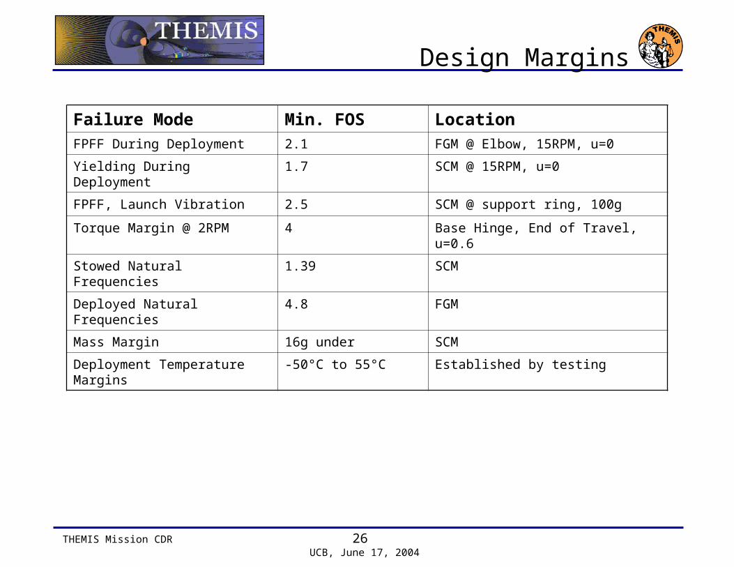
Failure Mode Min. FOS LocationFPFF During Deployment 2.1 FGM @ Elbow, 15RPM, u=0
Yielding During Deployment 1.7 SCM @ 15RPM, u=0
FPFF, Launch Vibration 2.5 SCM @ support ring, 100g
Torque Margin @ 2RPM 4 Base Hinge, End of Travel, u=0.6
Stowed Natural Frequencies 1.39 SCM
Deployed Natural Frequencies 4.8 FGM
Mass Margin 16g under SCM
Deployment Temperature Margins -50°C to 55°C Established by testing

THEMIS Mission CDR 27 UCB, June 17, 2004
Mass & Power
• Mass
• Power• 25W transient for Frangibolt deployment.
mass [g]SCM BASE 326SCM DAD 86SCM BOOM 174SCM INST ADAPTER 48SCM BOOM TOTAL 634SCM BOOM BUDGET 650
mass [g]FGM BASE 374FGM DAD 97FGM ELBOW 121FGM BOOM 300FGM INST ADAPTER 50FGM BOOM TOTAL 942FGM BOOM BUDGET 970

THEMIS Mission CDR 28 UCB, June 17, 2004
Fabrication and Assembly
Documentation• All fabrication and assembly processes are developed and
documented as Manufacturing Process Instructions.
• Any fabrication work and assembly will be logged.
Fabrication• Boom tubes – In-house
• Hinges – external machine shops.
Assembly• Bonding boom tubes and end fittings.
• Assembling hinges, harness and Frangibolt.

THEMIS Mission CDR 29 UCB, June 17, 2004
Composite Boom Fabrication
• In-house capability to manufacture composite tubes using the table rolling process.
• Bldg 151,Richmond Field Station (RFS).
• In service since March 2004. Prototype boom tubes successfully fabricated.
Table Roller Shrink Tape Wrapper Oven Mandrel Puller
THEMIS Mission CDR 30 UCB, June 17, 2004
Integration Plan
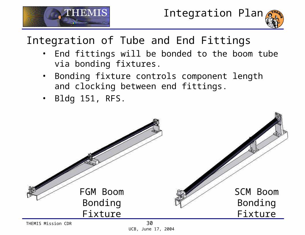
Integration of Tube and End Fittings• End fittings will be bonded to the boom tube via bonding
fixtures.
• Bonding fixture controls component length and clocking between end fittings.
• Bldg 151, RFS.
FGM BoomBonding Fixture
SCM BoomBonding Fixture

THEMIS Mission CDR 31 UCB, June 17, 2004
Assembly Plan
Assembly of hinges• Assemble base hinge, and DAD boxes. Do not assemble
elbow hinge can assembled.
Integration of harness• Harness, without connectors, will be threaded through
booms before assembling of boom. For the FGM, harness must also be threaded through the elbow before it is assembled.
Assembly of mag boom• Assemble hinges and tubes with end fittings.
Integration of Frangibolts• Frangibolts will be installed after boom is
assembled.

THEMIS Mission CDR 32 UCB, June 17, 2004
ETU Testing Plan
ETU Testing Plan• Vibration test for composite boom tubes.
• Mechanical characterization of composite materials.
• Proof testing of bonded joints subjected to survival temperature limits.
• Deployment testing at low and high deployment temperature extremes.
• Boom (tube and end-fittings) proof testing.
• Deployment testing at ambient conditions.

THEMIS Mission CDR 33 UCB, June 17, 2004
Flight Unit Testing Plan
• Flight Unit Testing Plan• Ambient deployment
• Vibration
• Ambient deployment
• Deployment test at deploy cold extreme minus 10C
• Deployment test test at deploy hot extreme plus 10C

THEMIS Mission CDR 34 UCB, June 17, 2004
ETU Testing
Boom Vibration• Adjustable mounting on the shaker to test different support
lengths for FGM and SCM booms.
• Test will take place at Wyle Laboratories, Santa Clara
• Sine and random as per THEMIS requirements.

THEMIS Mission CDR 35 UCB, June 17, 2004
ETU Testing
Mechanical Characterization of laminate• A laminate will be constructed and a coupon used for
stiffness and strength.
• Four point bending test.
Proof testing of bonded joints.• An end fitting will be bonded to short lengths of the
magboom and thermal cycled to THEMIS requirements.
• A tensile proof test of the bonded joint is carried out after thermal cycling.
Composite boom with end fittings• Tensile proof test after thermal cycling.

THEMIS Mission CDR 36 UCB, June 17, 2004
Deployment Test Plan
Non-Ambient Testing• Thermal vacuum test for hinge operation.
• Horizontal deployment at -50°C to 55°C.
Ambient Testing• Spinless Horizontal Deployment
– Gravity off-load fixture using air bearings.– Conservative test for torque margin due to lack of spin.
• Vertical Gravity-Assisted Deployment– Gravity used to simulate centrifugal force at end of stroke.– Conservative test for latch up load due to large force at end
of stroke.
THEMIS Mission CDR 37 UCB, June 17, 2004
Deployment Test Plan
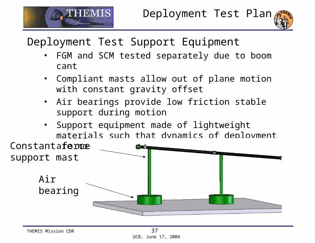
Deployment Test Support Equipment• FGM and SCM tested separately due to boom cant
• Compliant masts allow out of plane motion with constant gravity offset
• Air bearings provide low friction stable support during motion
• Support equipment made of lightweight materials such that dynamics of deployment are not affected
Constant force support mast
Air bearing
THEMIS Mission CDR 38 UCB, June 17, 2004
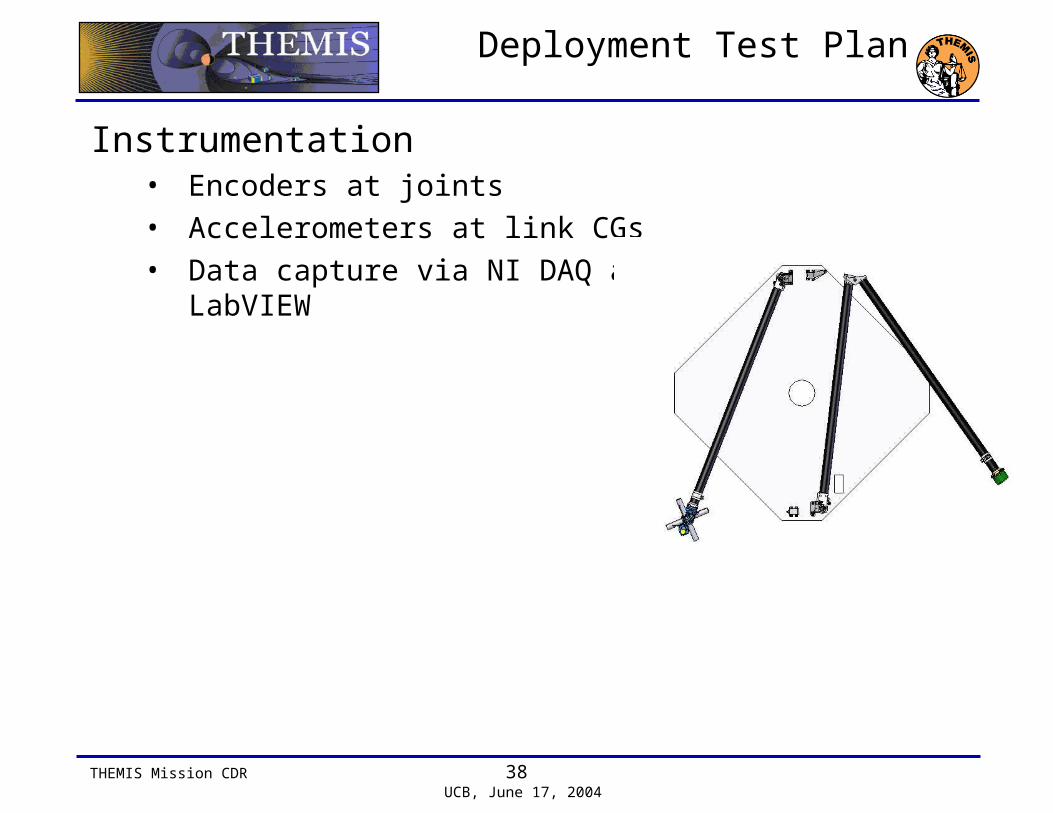
Deployment Test Plan
Instrumentation• Encoders at joints
• Accelerometers at link CGs
• Data capture via NI DAQ and LabVIEW

THEMIS Mission CDR 39 UCB, June 17, 2004
Test Plan
Vibration Test Plan• Assembled boom will be tested at Wyle Laboratories, Santa
Clara
• Sine and random as per THEMIS requirements.
Thermal Testing
THERMAL VACUUM
(# CYCLES)THERMAL AIR
(# CYCLES)
THERMAL LIMITS
(OPERATING, DEPLOY)
THERMAL PREDICTS
THERMAL TEST LIMITS (QUAL)LIMITS +/-10C VAC; +/-15C
AIR
THERMAL TEST LIMITS (ACC)
PREDICTS +/-10C VAC; +/-15C AIR
FGM Boom 1 8 -40 to +45 -15 to +39 -50 to +55 -25 to +50 SCM Boom 1 8 -40 to +45 +4 to +43 -50 to +55 -25 to +55
THEMIS Mission CDR 40 UCB, June 17, 2004
Performance Assurance
Procedures• During personnel, all assembly must follow established
Manufacturing Process Instructions.
• Work performed on each assembly will be logged.
Documentation• Manufacturing Process Instructions for
– Tube fabrication– Bonding of hinge and tubes– Assembly of hinge, and harness– Installation of frangibolts

THEMIS Mission CDR 41 UCB, June 17, 2004
Schedule
ETU • Assembly - 6/18/04
• Deployment Testing - 7/2/04
Flight • Tubes and Hinges - 7/30/04
• Assembly – 8/2/04 to 9/15/04
• Testing – 9/23/04 to 11/11/04
THEMIS Mission CDR 42 UCB, June 17, 2004
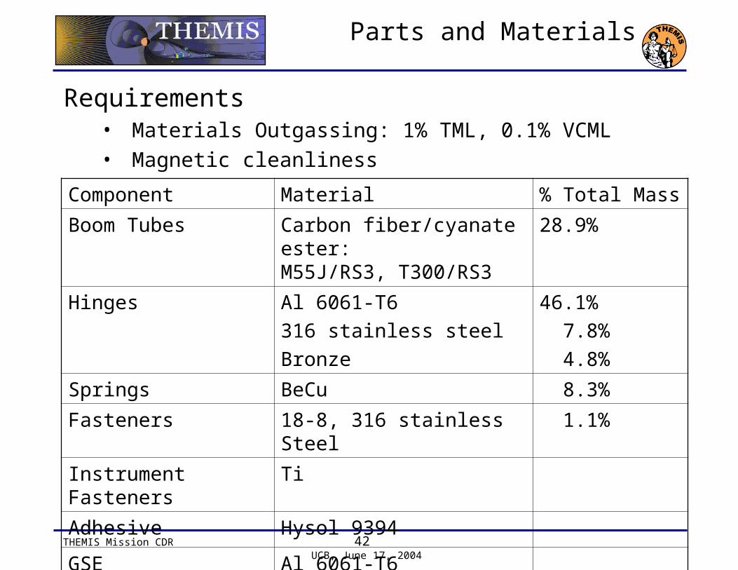
Parts and Materials
Requirements• Materials Outgassing: 1% TML, 0.1% VCML
• Magnetic cleanliness
Component Material % Total Mass
Boom Tubes Carbon fiber/cyanate ester: M55J/RS3, T300/RS3
28.9%
Hinges Al 6061-T6
316 stainless steel
Bronze
46.1%
7.8%
4.8%
Springs BeCu 8.3%
Fasteners 18-8, 316 stainless Steel 1.1%
Instrument Fasteners Ti
Adhesive Hysol 9394
GSE Al 6061-T6

THEMIS Mission CDR 43 UCB, June 17, 2004
Contamination Control
Magnetic cleanliness• Comply with Magnetics Cleanliness standard described in
the THEMIS Magnetics Control Plan
• Use of non-magnetic materials e.g. Al, carbon-fiber for mag boom.
• Non-magnetic tools.
Electrostatic cleanliness• Comply with THEMIS Electrostatic Cleanliness Plan
• Keep exposed surfaces of the mag boom conductive by minimizing exposed hard anodizing, exposing outer layers by grinding down epoxy.