the x-38 spacecraft
TRANSCRIPT

- .. ~ "-- - ._ ... _ ---
The X-38 Spacecraft Fault-Tolerant Avionics System . Coy Kouba' , Deborah Buscher' , Joseph Busa2
1. NASA-Johnson Space Center, Houston, TX 2. Charles Stark Draper Laboratories, Cambridge, MA
ABSTRACT
Source of Acquisition NASA Johnson Space Center
In 1995 NASA began an experimental program to develop a reusable crew return vehicle (CRV) for the International Space Station. The purpose of the CRY was threefold: (i) to bring home an injured or ill crewmember; (ii) to bring home the entire crew if the Shuttle fleet was grounded; and (iii) to evacuate the crew in the case of an imminent Station threat (i.e. , fire, decompression, etc). Built at the Johnson Space Center, were two approach and landing prototypes and one spacecraft demonstrator (called V20 1). A series of increasingly complex ground subsystem tests were completed, and eight successful high-altitude drop tests were achieved to prove the design concept. In this program, an unprecedented amount of commercial-off-the-shelftechnology was utilized in this first crewed spacecraft NASA has built since the Shuttle program. Unfortunately, in 2002 the program was canceled due to changing Agency priorities. The vehicle was 80% complete and the program was shut down in such a manner as to preserve design, development, test and engineering data.
This paper describes the X-38 V201 fault-tolerant avionics system. Based on Draper Laboratory' s Byzantine-resilient fault-tolerant parallel processing system and their "network element" hardware, each flight computer exchanges information on a strict timescale to process input data, compare results, and issue voted vehicle output commands. Major accomplishments achieved in this development include: (i) a space qualified two-fault tolerant design using mostly COTS (hardware and operating system); (ii) a single event upset tolerant network element board, (iii) on-the-fly recovery of a failed processor; (iv) use of synched cache; (v) realignment of memory to bring back a failed channel; (vi) flight code automatically generated from the master measurement list; and (vii) built in-house by a team of civil servants and support contractors.
This paper will present an overview of the avionics system and the hardware implementation, as well as the system software and vehicle command & telemetry
:'~~:: ential imprrents and less s learned ~rr. fO
l/-I

1---·
I. AVIONICS ARCHITECTURE OVERVIEW
The X-38 V201 avionics architecture is a four string, two-fault tolerant avionics system. The central part of the avionics architecture is the four Flight Critical Computer's (FCCs) and the Network Element Fifth Unit (NEFU). Each FCC consists of a Flight Critical Processor (FCP), an Instrumentation Control Processor (ICP), a Network Element (NE) card, two Multiprotocol/RS-422 cards, four Digital Output (DO) cards, an Analog Output (AO) card, and an lRIG-BlDecomm card. A simplified view of the architecture is pictured below.
""
Vdlkk l!q. ipmau Vcbidc.Eq.iplllQ\
Figure 1: X-38 I V201 Avionics Architecture
eTC - Command .. T'''IM~ CompuIW FCC - Flight CritoeaJ CornpMr FTPP-F,lAToIw.I'IIP.r.IleIProc:u,Of GSE-Oround SI4lJlOl1 EqUlPlTlenl NEFU - ,"!Work EIM1ton1 Ftt. Unit
proces or. Tliis boa d is also a Radstone Power P 604R single-board computer that runs the VxWorks operating system. This board obtains the majority of its sensor information from the Data Acquisition Units (DAUs) via an IRIG-BlDecomm
I _._----
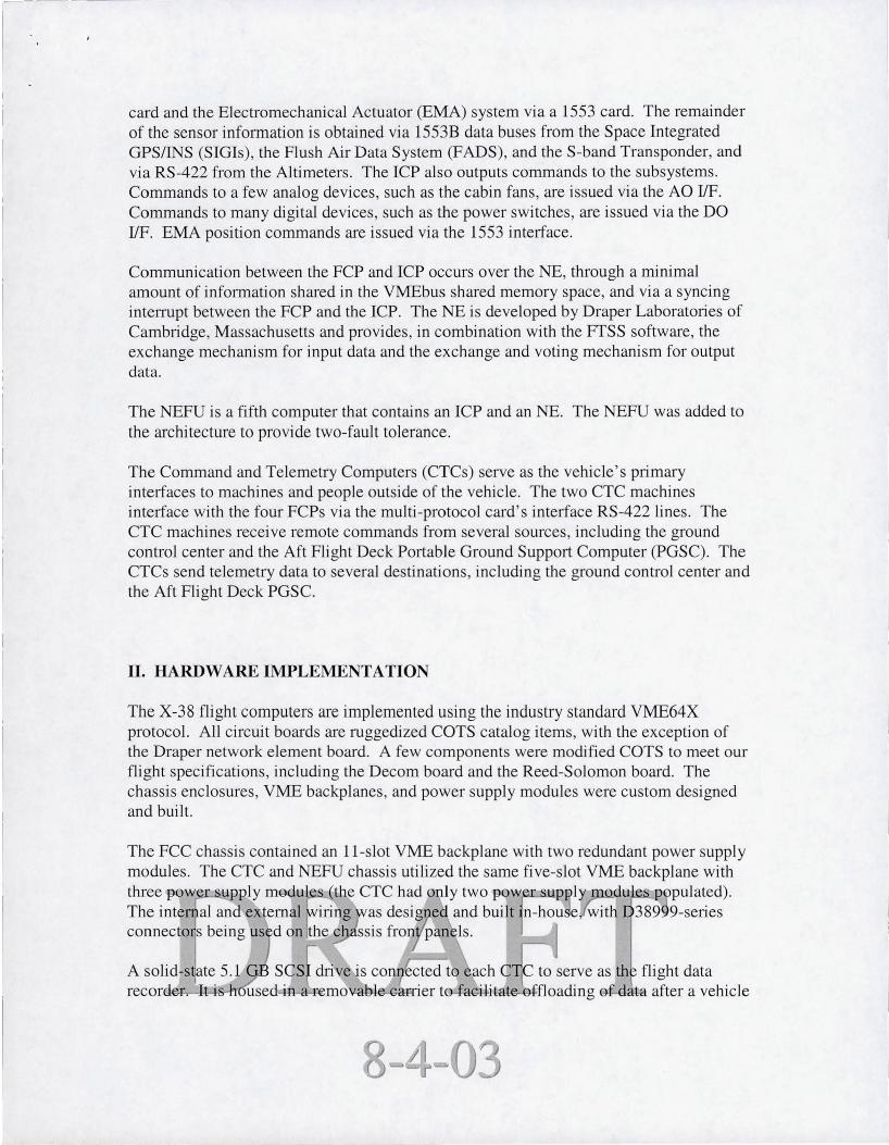
card and the Electromechanical Actuator (EMA) system via a 1553 card. The remainder of the sensor information is obtained via 1553B data buses from the Space Integrated GPSIINS (SIGIs) , the Flush Air Data System (FADS), and the S-band Transponder, and via RS-422 from the Altimeters. The ICP also outputs commands to the subsystems. Commands to a few analog devices, such as the cabin fans, are issued via the AO lIF. Commands to many digital devices, such as the power switches, are issued via the DO IfF. EMA position commands are issued via the 1553 interface.
Communication between the FCP and ICP occurs over the NE, through a minimal amount of information shared in the VMEbus shared memory space, and via a syncing interrupt between the FCP and the ICP. The NE is developed by Draper Laboratories of Cambridge, Massachusetts and provides, in combination with the FfSS software, the exchange mechanism for input data and the exchange and voting mechanism for output data.
The NEFU is a fifth computer that contains an ICP and an NE. The NEFU was added to the architecture to provide two-fault tolerance.
The Command and Telemetry Computers (CTCs) serve as the vehicle ' s primary interfaces to machines and people outside of the vehicle. The two CTC machines interface with the four FCPs via the multi-protocol card ' s interface RS-422 lines. The CTC machines receive remote commands from several sources, including the ground control center and the Aft Flight Deck Portable Ground Support Computer (PGSC). The CTCs send telemetry data to several destinations, including the ground control center and the Aft Flight Deck PGSC.
II. HARDWARE IMPLEMENTATION
The X-38 flight computers are implemented using the industry standard VME64X protocol. All circuit boards are ruggedized COTS catalog items, with the exception of the Draper network element board. A few components were modified COTS to meet our flight specifications, including the Decom board and the Reed-Solomon board. The chassis enclosures, VME backplanes, and power supply modules were custom designed and built.
-

r-------
test or rrusslOn . Each CTC continuously writes FrPP status data to these drives during normal operation .
A number of FPGAs were utilized on the network element board (and many of the COTS boards too). The NE had three Xilinx and Actel FPGAs to incorporate the state machine design of the NE.
During the development of the X-38, these flight computers underwent a rigorous qualification and acceptance program, including extensive functional testing (using both flight software and special test routines) , thermal-vacuum testing, vibration testing, and radiation testing.
III. FAULT-TOLERANCE PARALLEL PROCESSING SYSTEM
FfPP The FfPP is a fault tolerant parallel processing Byzantine resilient system that is realized by utilizing hardware components known as Network Elements (NE). These NEs act as arbiters that connect a redundant set of computers, each considered fault containment regions, to each other as well as to external systems in a manner that implements Byzantine resilience in a parallel processing environment.
FfSS The Fault Tolerant System Software (FfSS) is a software layer, woven around the OS and works intimately with the FfPP, which allows the developer of the Flight Application the ability to program as if they were running on one computer. The FfSS handles the low-level ability to run this Application in parallel across separate processors , in lockstep, leaving the developers no concem over this parallel nature or redundancy of the system. The Flight Application simply reads from inputs, which the FfSS ensures is congruent across all computers, then writes their output, which the FfSS votes on and delivers. The developer is further relieved from performing health and monitoring of these systems as FfSS performs intensive fault detection , isolation, and recovery.
Commanding/Telemetry Commanding and Telemetry were dealt with in a different fashion than the rest of the system. In a perfect world, the telemetry and commanding would have been pumped through the Network Elements via the ICPs. However, telemetry and commanding in combination at high data volume and a 10hz rate would have bogged down the system and could have preempted high priority flight critical data. It was detelmined to be in the best iIltere 0 take these a i ems off the !'Network Ie entp th et a re to all rules govern · n~ the . The s Jution as to pul t e commantis and send tel etr- to/from a separate rrO board c ned the M hi-Proto I ntrol 0 puter (MPCC) Bringing commands into the light C . ·cal Comp ter was acco plis ed by rea ng the commands from the MP C at 10hz fro the red ndant s.et, voting on th health of each MPC h€m>Se ct tw h@lthies nes-.tg sing r~~hange thei GQ mands to the NE. It was decided to not vote the telemetry at all through the Network Element.

Theoretically the only difference in the data across the redundant computers was the time-stamping itself of the data. The telemetry was simply pumped out the MPCC board at 10hz to a recording device and eventually transmitted to the ground by a separate system.
Asynchronous 110 in a Parallel Processing Byzantine Resilient Environment In the X-38 architecture, Telemetry is sent down at 10hz. In general, all 110 performed from the FCP should pass through the ICP via 50hz synchronous pipes and then disseminated appropriately. This however, would create a major bottle-neck to communication services (i.e. Network Element) and would stress the already heavily loaded ICP. Instead, the FCP writes its telemetry to a separate board, known as the MPCC, on the VME back-plane. The MPCC is then commanded to transmit the data stream over RS-422 to a Command and Telemetry Computer (CTC), which in tum transmits this data stream to the ground. Several issues arose in trying to successfully bypass the ICP and thereby levy the load off the Network Element. In a full-up Quad scenario, telemetry would be written to the MPCC across four different back-planes. This, in itself, can be considered four asynchronous events absent the Network Element, especially when moving large amounts of data. Complicating the matter further, an enor may occur during communication to the MPCc. This may cause a longer writing duration in a re-send scenario or perhaps complete termination of the write altogether which would cause the process to end early. In all , each FCP may return from the telemetry write at different times and could cause loss of channel synchrony. The Telemetry task residing on the FCP should never cause a loss of channel synchrony, as it is not considered a fJight-critical process. The solution implemented was to begin by getting an initial time-stamp from a highly accurate local clock on the FCP that is synchronized with the Quad every 1hz. Then , execute the VME access . Finally, a spinlock is performed on the clock until a conservative pre-determined maximum timeout val ue is reached.
Duration of asynchronous channel events are identical
------------~------------r "'\
D I sync I I time I VM E access ~Iocks ... slam p spin·lock t
ti meout sync point
Figure: Asynchronous 110 Events As shown in the Figure above, in its worst case, this solution allows each of the channels to peifb . asy chronousl , nd then finally ynchromze -en h time un ue is reache .
-

construction, and remote command reception and execution. The FTSS software in combination with the JSC provided Vehicle, Mission, and Power Management software provides a basic environment in which applications, such as flight control, can execute and meet all necessary timing requirements.
The NB interface between the rcp and FCP serves several functions , including the exchange of sensor data from the rcp to the FCP. An example of a two round exchange of a single piece of data from one rcp to four FCPs via the NBs is shown in the figure below. All rcp data is treated as simplex data that is being passed to a quadraplex group. This is due to the fact that the sensors and effectors are not redundant across the four reps. rnstead, the I/O profile of the X-38 201 vehicle is redundant and/or cross-strapped in only the key areas necessary for vehicle flight , life support, and environmental control.
The figure below shows a single input value being read into the rep and exchanged via a two round exchange over the NBs to all four FCPs. If that single input value is "bad" (i.e. , the sensor has hard-over failed) that "bad" value would be exchanged via the NBs just like any other vaJue. It is up to the application software to determine if the value is "bad."
During the first round of the exchange, the data is sent from one NB to all of the NBs. During the second round of the exchange, the data is sent from all five NBs to all five NBs again . This two round exchange is necessary because 1) the reps are not synced during the first exchange (i.e. , all four reps are running independently and in simplex mode) and 2) the second exchange is necessary to verify that the data exchanged in the first round was received properly by all NBs.
J

Single Value
NE
Two Round Exchange Example -On Input Data
Round 1 Round 2
NE 3
NE 3
E 3
E 3
NE
Figure 2.2.2: Two Round Exchange Example - On Input Data
FCP # l
FCP #2
FCP #3
FCP #4
One of the primary jobs of the FCP computer is to run FC and NFC applications. These applications each consi st of several parts 1) sensor Subsystem Operating Procedure (SOP) code, which contains sensor data conversion routines, sensor redundancy management routines , and sensor fault detection , isolation , and recovery routines, 2) application code, which takes these sensor inputs and uses them in equations to produce effector commands, 3) effector reverse SOPs, which convert the commands from engi eering units to raw effector units, and ) code for processi g remote co mands corning f om the g ound engi ee s or Shuttle crew.

other tasks in that rate group. Data transfer between tasks in a different rate group is performed via FrSS communication services sockets. Since FCP applications do not have access to non-congruent data, FrSS communication services will by-pass the use of the NEs.
The two figures below shows end-to-end how the ICP brings in sensor data, how the application operates on that data and produces an effector command, and how the effector command is output to the ICP.
Three Sensor Example
0.355, 0.356, and 0.355
· Two round exchange occurs over NE like in previous example.
0.355, 0.356, and 0.355
Read(S IGII) Read(S IGI2) Read(S IGI3)
SIGI 3 0.355
Send(SIGI3)
o
• ICP3 obtains data via 1553 and perfonns a SClld(SIGI3) • Two round exchange occurs over NE like in previous example. • Tllis is independent of tile SIGJ I ruld SIGl2 exchange. • Fep3 does three reads - Read (SIGI3), Read (SIGI2), and Read (SIGI I). • Fep3 now has 0;\355, 0;\356, and Ox355 as values for the three SIGI
reads. Read(S IGII) SIGI2 Read(S IGI2) 0.356
Read(S IGI3) Send(SIG12) 0.355, 0.356, and 0.355
• FCP4 participates in the two round exchange which occurs over the NE like in lhe previous example.
• FCP4 does three reads · Read (SIGI3), Read (S IGI2), and Read (SIGII ). • FCP4 now has Ox355. Ox356, and Ox355 as values for the three SIGI
reads.
0.355, 0.356, and 0.355
• lePI obtains data via 1553 and perfonns a Send(S IGII )
Read(S IGII ) Read(S IGI2) Read(S IGI3)
SIGII 0.355
Send(SIGII )
• Two round exchange occurs over NE like in previous example. • This is independent of the SIGI2 and SIGI3 exchange. • FCPI does three reads - Read (SIGl3), Read (S IGI2), and Read (S IGII ). • FCP lnow has 0x355, Ox356. and Ox355 as values for the three SIGI
reads.
• lepz obtains data via 1553 and perfonns a Send(SIGI2) · Two round exchange occurs over NE like in previous exam ple. · This is independent or the S IGII and S IGI3 exchange. • FCPZ does three reads - Read (S IGl3), Read (S IGI2), and Read (S IGI J). • FeP2 now has 0x355. 0x356, and Ox355 as values for the three S IG I
reads.

,--------I
• GN&C is notified that tlte SIGI data is ready. Three Sensor Example, cntd. • GN&C perfonns SOP function, FDlR, and RM. Decides solution
is really Ox355. • This value is used in a GN&C equation, which produces an EMA 5. 1
position value of 5. 1. o The reverse SOP is called fo r output.
Write(EMA I)
• The application then does a Write(EMA 1) to the NE. • A single round voted exchange occurs, because all four Feps
are synced. The output is 5.0. Error in FCP4 is masked by voters in NE. • FfSS FDIR will dClcmline how to (feat FCP4 (i .e. , detennine if this is a
transient error or pennanent ; RM will be dependent on FIt. Mgr defined RM policy in force for that panicular mission phase.
• A 11 four ICPs and each Fep receive the broadcast output value and it is the ICPs responsibility to detenlline which lep is channelized to which EMA controller.
5.0
Read(EMA I)
• GN&C is notified that the S IGI data is ready. • G &C perfonns SOP function, FDlR, and RM . Decides so lution is
really 0.355. • This va lue is used in a GN&C equation, which produces an EMA
position value of 5.0. • The reverse SOP is called for output. • The applicat ion then does a Write(EMA I) to the NE. • A single round voted exchange occurs, because all four FCPs
are synced. The output is 5.0. FCP4 is masked by voters in NE. • FTSS FDlR wi ll detennine how to treat FCP4 (i.e ., detennine if this is a
transient error or penn anent; RM will be dependent on At. Mgr defined RM policy in force for that particular mission phase.. 5.0
• All four (CPs and each FCP receive the broadcast output value and Write(EMA I) it is the ICPs responsibility to detennine which ICP is channelized to which EMA controller.
• GN&C is not ified thnt the SIGI dma is ready. 5.0 • GN&C perfonns SOP function, FOlR, and RM . Decides solution
is rea lly Ox355. Read(EMA I). This value is used in a GN&C equation , which produces an EMA
C
5.0
position value of 5.0. • The reverse SOP is called for output. • The application then does a Write(EMA I) to the NE. • A single round voted exchange occurs, because all four FCPs
are synced. The output is 5.0. FCP4 is masked by vote~ in NE. • PfSS FDlR will detennioc how to treat FCP4 (i .e., detennine iflhis
is a transient error or pennanent; RM will be dependent on F1t. Mgr defined RM policy in force for that particular miss ion phase.)
• All four (CPs and each FCP receive the broadcast outpu t va lue and it is the lCPs respons ibility to detennine which IC P is channe lized to which EMA controller.
B Write(EMAI )
5.0
5.0
Read(EMAI )
• GN&C is not ified that the SIGI data is ready. • GN&C perfonns SOP function, FDlR, and RM . Decides solution is
really Ox355_ • This value is used in a GN&C equation, which produces an EMA
position value of 5.0. • The reverse SOP is called for output. • The application then does a Write(EMA I) to the NE. • A single round voted exchange occurs, because all fOUI FCPs
are synced. The output is 5.0. FCP4 is masked by voters in NE. • FTSS FDlR will detemline how to treat FCP4 (i.e., detennine if this
is a transient error or penn anent; RM will be dependent on Fit, Mg r defined RM policy in force for that particular mission phase,
• All four ICPs and each FCP receive the broadcast output value and Read(EMA I) it is the ICPs responsibility to detemline which ICP is channelized
to which EMA controller.
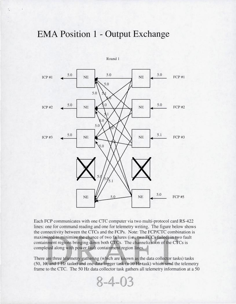
Once the application has completed computation of the sensor data, the application produces an effector command response. The figure below shows how all four FCPs produce the EMA position command at the same time and a single round exchange occurs via the NE. In this case, three of the four FCPs have produced a solution of 5.0. A fourth FCP has produced a solution of 5.1. No FCPs have timed out, so all processors are in sync. Upon the completion of the single round exchange, a voted output is sent (i .e. , 5.0) to all four rcps. The 5.1 position that FCP #4 produced is masked out. The voted output is broadcast to all FCPs and to all four rcps. This voted broadcast allows both the rcps to recei ve the output command and the FCPs to 1) recei ve the output command, which can then be placed in the telemetry stream, and 2) receive any syndrome data on the output vote, which will in turn be used in ¥ISS FDr to determine whether or not a processor or NE has a problem and needs to be voted out or powered off. All of the rcps receive all commands. This allows the FCP, for the most part, to be independent from the effector configuration. It is the rcP's responsibility to know their own identity and what I/O devices are attached to them.
\

EMA Position 1 - Output Exchange
Round 1
rcp #1 5.0
NE 5.0
NE 5.0
rCP#2 5.0 NE NE
5.0
ICP#3 5.0
NE NE 5.0
rCP#4 5.0
NE NE 5.1
NE
FCP#l
FCP#2
FCP#3
FCP#4
\ \
EMA Position 1 - Output Exchange
Round 1
ICP #1 5.0
NE 5.0
NE 5.0
FCP#l
ICP#2 5.0
NE NE 5.0
FCP#2
ICP#3 5.0
NE NE 5.1
FCP#3
~5 55.1 ~ NE 5.0 NE
5.0 FCP#5
Each FCP communicates with one CTC computer via two multi-protocol card RS-422 lines: one for command reading and one for telemetry writing. The figure below shows the connectivity between the CTCs and the FCPs. Note: The FCP/CTC combination is maximized .. t minimize t hance of two fail ures (i . . , tw. CCs ailed . t 0 fault containm nt region'S brin&ing Cio ' n both C s. The c ~nnelization of t e CTCs is complete along wi po~er fa t contain · en egion lines.
There are three tel et·y gathering (w lch are own as the data collector tasks) tasks (50, 10, d H task-s)-.and onooat-a egger task a l-Q-I:IZ...task) whiG1:H;ood the telemetry frame to the CTC. The 50 Hz data collector task gathers all telemetry information at a 50

I
I
Hz rate and passes it to the 10 Hz data logger task. The 10 Hz data collector task gathers all telemetry information at a 10 Hz rate and passes it to the 10 Hz data logger task. The 1 Hz data collector task gathers all telemetry information at a 1 Hz rate and passes it to the 10 Hz data logger task. The 10 Hz data logger task then constructs each telemetry frame and, at a 10 Hz rate, outputs a telemetry stream of data to each CTC.
After the telemetry stream write is complete the FCPs read data from the CTC to which they are attached. There will always be a command (even if it is a null command or a repeated command) and status data available to be read.
IV. FUTURE WORK & CONCLUSIONS
The current configuration in the X-38 is fully Byzantine resilient up to the 110 Processor. After that, due to cost and weight concerns, the flow beyond is susceptible to Byzantine errors; though each hardware instance has a minimum of 1 fault tolerance. Improving this system would include implementing the Byzantine philosophy throughout the entire breadth of the system, beyond the Flight Critical components.
Potential improvements to the hardware could be:
(i) Removing the fiber optic links: these components are very fragile to handling and are damaged easily. The fiber optic components also required us to significantly increase the size of each flight chassis due to the minimum bend radius of each fiber cable. An alternative would be to replace them with copper connects using optocouplers to provide isolation.
(ii) Improve the Network Element' s throughput to reduce the overloading bottleneck. This would require a Draper design change.
(iii) Use faster FCP and rcp processor boards to also increase throughput
(iv) Implement greater radiation tolerance by upgrading certain parts on the Network Element.
(v) Recent improvements in ruggedized COTS components could also lead to a faster and smaller hardware implementation.
JSC2930 , X-38 Y.ehicle 01 Software t, Version 2.3 , Decemge 1-999, usche,
-

Flight Data Recorder #1
28V pwr ----'L, __ --;: __ _
SCSI
Ethernet, RS-232 . ~
S-band ~ RS -422
PLD umbilical .----J UHF . RS-232 :
CTC 1
health status • I 28V pwr ~
L-___ _
Ethernet, RS-232 . ~ I CTC 2 S-band ~ RS-422
PLD umbilical UHF . RS-232 :
health status • I 28V pwr ~
SCSI
Flight Data Recorder #2
....
RS-422
RS-422
-, .;1
1_ ~ Discrete outputs
__________ ~~~ Analog outputs
... ~ 1553 bus
..... IRIG-B PCM data """" ... ~ Ethernet, RS-232, RS-422, health status
" I'" 28V pwr
r-:-"",:---:-:-~-'-----------.~ Discrete outputs I __________ --.~ Analog outputs
... ~ 1553 bus
... IRIG-B PCM data
... ~ Ethernet, RS-232, RS-422, heal th status
F:r~?L:~ :';,':.1": I. 28V pwr
[ ',I ~ Discrete outputs _ ~ Analog outputs
... ~ 1553 bus
... IRIG-B PCM data
... ~ Ethernet, RS-232, RS-422, health status
F,.·;~j'!-:.r:<t~I... 28V pwr
I __________ .~ Discrete outputs I __________ .~ Analog outputs
... ~ 1553 bus
... IRIG-B PCM data
... ~ Ethernet, RS-232, RS-422, health status
:~I" 28V pwr
L' I ~I NEFU I ~ Ethernet, RS-232, health status :1:- 14.:--