the whitman companies, inc
TRANSCRIPT

SDMS Document THEWHITMANCOMPANIES, INC.Setting the Standard inEnvironmental Engineering & Management 307213
FIRST AMENDED TECHNICAL MEMORANDUMFOR
DEVELOPMENT AND SCREENING OF ALTERNATIVES FOR SITEREMEDIATION
FORROCKAWAY BOROUGH WELL FIELD SITE
OPERABLE UNIT #3FOR PROPERTY OF
KLOCKNER & KLOCKNERROCKAWAY BOROUGH, NEW JERSEY
SUBMITTED ToUSEPA-REGIONII
EMERGENCY <&_ REMEDIAL RESPONSE DIVISIONNEW YORK, NEW YORK
SUBMITTED BYTHE WHITMAN COMPANIES, INC.
ON BEHALF OF KLOCKNER & KLOCKNER
IN ACCORDANCE WITHADMINISTRATIVE ORDER ON CONSENT
INDEX No. II-CERCLA-95-0104
MARCH 2005
MICHAEL NfMETLrrz IRA L. WHITMAN, PH.D., P.E.PROJECT MANAGER PRINCIPAL CONSULTANT
116 Tices Lane, Unit B-1, East Brunswick, NJ 08816www.whitmanco.com
G:\PROJECTS\1995\95-03-02 KlocknertR-Techmemo-March 2005.DOC

THEWHITMANCOMPANIES, INC.
Corporate Headquarters116 Tices Lane, Unit B-1East Brunswick, NJ 08816
Tel: 732.390.5858 • Fax: 732.390.9496Email: [email protected]
Internet: www.whitmanco.comSeptember 16, 2004
Chief. New Jersey Superfund Branch IEmergency & Remedial Response DivisionU.S. Environmental Protection Agency, Region II290 Broadway, Floor 19New York, NY 10007
Attn: Brian Quinn, Project Manager
RE: First Amended Technical MemorandumKlockner & KlocknerRockaway Borough Wellfield Superfund SiteAdministrative Order on Consent ("AOC")Index No. II-CERCLA-95-0104Whitman Project #95-03-02
Dear Mr. Quinn:
In compliance with Paragraph 34 of the above AOC, Task VIII of the Statement of Work and the U.S.Environmental Protection Agency's (EPA's) January 20, 2005 comments concerning Klockner andKlockner's September 16, 2004 Technical Memorandum for Development and Screening of Alternatives forSite Remediation for the above referenced site, enclosed are four copies of the First Amended TechnicalMemorandum for Development and Screening of Alternatives for Site Remediation (TechnicalMemorandum). The Technical Memorandum incorporates EPA's January 20, 2005 comments.
If you have any questions or comments concerning the Technical Memorandum, please contact me at(732)390-5858.
Very truly yours,
hKchael N.
Senior Project Manager'Bharti Ujjani, d.Vice President $h/ironmental Health & Safety
MNM/ ,Enclosurecc: Frances Zizila, Assistant Regional Counsel, EPA
Dan Klockner, Klockner & KlocknerJennifer Peterson, Esq., Riker Danzig, Scherer, Hyland & PerrettiDonna Gaffiean, NJDEP
307214
Setting the Standard in Environmental Engineering & Management
G:\PROJECTS\I99S\9S-03-02 KlocknfrtL.OJ0105EPA.dot

li
I!
FIRST AMENDED TECHNICAL MEMORANDUM FOR DEVELOPMENTAND SCREENING OF ALTERNATIVES FOR SITE REMEDIATION
ROCKAWAY BOROUGH WELL FIELD SITEOPERABLE UNIT #3FOR PROPERTY OF
KLOCKNER & KLOCKNERROCKAWAY BOROUGH, NEW JERSEY
Table of Contents
1.0 INTRODUCTION 11.1 Purpose of Report 11.2 Report Organization 2
2.0 SITE BACKGROUND 22.1 Klockner Property Location 22.2 Site History 32.3 Development and Screening of Alternatives for Site Remediation 4
3.0 CERCLA CRITERIA USED TO EVALUATE REMEDIATIONALTERNATIVES 4
4.0 DEVELOPMENT OF REMEDIAL ACTION OBJECTIVES 44.1 Cleanup Criteria for TCE, PCE and Lead 4
4.1.1 Contaminants of Concern Identified on Subject Site 54.1.2 Cleanup Criteria 5
4.2 Media to Which Remedial Action Applies 64.3 Identification of Volumes or Areas of Media 7
4.3.1 TCE and PCE Contamination 74.3.2 Lead Contamination 8
5.0 DEVELOPMENT AND SCREENING OF REMEDIAL TECHNOLOGIES ANDPROCESS OPTIONS 85.1 Introduction 85.2 Identification of Remedial Technologies and Process Options Potentially
Available 95.2.1 Remedial Technologies and Process Options for TCE and PCE 95.2.2 Remedial Technologies and Process Options for Lead 105.2.3 Treatment Location 105.2.4 Screening Evaluation 105.2.5 Effectiveness Evaluation 105.2.6 Implementability Evaluation 115.2.7 Cost Evaluation ^. 11
307215THEWHITMANCOMPANIES, INC.
G:\PROJECTS\1995\95-03-02 Klockner\R-Techmemo-March2005.DOC

5.3 Description of Seriously Considered Remedial Technologies 155.3.1 No Action 15
5.3.1.1 Description 155.3.1.2 Applicability 165.3.1.3 Limitations 165.3.1.4 Data Needs 165.3.1.5 Performance Data 165.3.1.6 Cost 16
5.3.2 Monitored Natural Attenuation 165.3.2.1 Description 165.3.2.2 Applicability 165.3.2.3 Limitations 175.3.2.4 Data Needs 175.3.2.5 Performance Data 175.3.2.6 Cost 17
5.3.3 Institutional Control 175.3.3.1 Description 175.3.3.2 Applicability 175.3.3.3 Limitations 175.3.3.4 Data Needs 185.3.3.5 Performance Data 185.3.3.6 Cost 18
5.3.4 Capping/Containment 185.3.4.1 Description 185.3.4.2 Applicability 185.3.4.3 Limitations 195.3.4.4 Data Needs 195.3.4.5 Performance Data 195.3.4.6 Cost 19
5.3.5 Excavation, Retrieval, and Off-Site Disposal 205.3.5.1 Description 205.3.5.2 Applicability 205.3.5.3 Limitations 205.3.5.4 Data Needs 205.3.5.5 Performance Data 215.3.5.6 Cost 21
5.3.6 Soil Vapor Extraction 215.3.6.1 Applicability 235.3.6.2 Limitations 235.3.6.3 Data Needs 235.3.6.4 Performance Data 245.3.6.5 Cost 24
5.3.7 In Situ Thermal Treatment 245.3.7.1 Electrical Resistance Heating 265.3.7.2 Radio Frequency/Electromagnetic Heating 265.3.7.3 Hot Air/Steam Injection 275.3.7.4 Applicability ._..„.... 27
307216THEWHITMANCOMPANIES, INC.
G:\PROIECTS\1995\95-03-02 Klockner\R-Techmemo-Marcli2005.DOC

II
1
5.3.7.5 Limitations 275.3.7.6 Data Needs 285.3.7.7 Performance Data 285.3.7.8 Cost 28
5.3.8 In-Situ Bioremediation 285.3.8.1 Description 285.3.8.2 Applicability 285.3.8.3 Limitations 295.3.8.4 Data Needs 295.3.8.5 Performance Data 295.3.8.6 Cost 29
5.3.9 Phytoremediation 305.3.9.1 Description of Phytoremediation 305.3.9.2 Enhanced Rhizosphere Biodegradation 305.3.9.3 Phyto-accumulation 305.3.9.4 Phyto-degradation 305.3.9.5 Phyto-stabilization 305.3.9.6 Applicability 315.3.9.7 Limitations 315.3.9.8 Data Needs 325.3.9.9 Cost 32
5.3.10 In-situ Chemical Oxidation 325.3.10.1 Description 325.3.10.2 Applicability 325.3.10.3 Limitations 335.3.10.4 Data Needs 335.3.10.5 Performance Data 335.3.10.6 Cost 33
6.0 INITIAL SCREENING OF PROCESS OPTIONS 346.1 Eliminated Process Options 34
7.0 DETAILED ANALYSIS OF ALTERNATIVES 387.1 Description of Remedial Alternatives 38
7.1.1 Description of Remedial Alternatives for TCE and PCE 387.1.1.1 Alternative 1: No Action 387.1.1.2 Alternative 2: Monitored Natural Attenuation,
Institutional and Engineering Controls 397.1.1.3 Alternative 3: Excavation - Off-site Treatment 417.1.1.4 Alternative 4: Partial Excavation and Off-Site Disposal 427.1.1.5 Alternative 5: Soil Vapor Extraction 42
7.1.2 Description of Remedial Alternatives for Lead 437.1.2.1 No Action 437.1.2.2 Institutional and Engineering Controls 447.1.2.3 Excavation and Off-site Disposal.: 45
307217
THEWHITMANCOMPANIES, INC.
G:NPRO3ECTS\1995\95-03-02 KlocknertR-Techmemo-March 2005.DOC

8.0 CONCLUSION 45
9.0 REFERENCES 47
TABLES
1. Relevant Cleanup Levels for Site Contaminants2. Evaluation of Process Options for TCE and PCE Remediation3. Evaluation of Process Options for Lead Remediation4. Screening and Elimination of Process Options for TCE and PCE5. Screening and Elimination of Process Options for Lead
FIGURES
1. Site Location on USGS Dover, New Jersey Quadrangle2. Site Map of Klockner Property3. 0-6 Foot Depth Soil Sample Results and Isopleth for TCE Building 124. 0-6 Foot Depth Soil Sample Results and Isopleth for PCE Building 125. Cross Section A-A'-Building 12 -TCE Results6. Cross Section B-B'-Building 12-TCE Results7. 0-6 Foot Soil Sample Results & Isopleth for PCE-Building 138. Cross Section C-C'-Building 139. Soil Sample Results and Sample Locations - Building 1210. Cross section B-B', Building 12 -PCE Results11. Cross Section D-D', Building 12 - PCE Results
ATTACHMENTS
1. Depth to Ground Water Information2. EPA's January 20, 2005 Letter
307218
THEWHITMANCOMPANIES, INC.
G:\PROJECTS\1995\95-03-02Klockner\R-Techmemo-March2005.DOC

FIRST AMENDED TECHNICAL MEMORANDUM FOR DEVELOPMENTAND SCREENING OF ALTERNATIVES FOR SITE REMEDIATION
ROCKAWAY BOROUGH WELL FIELD SITEOPERABLE UNIT #3FOR PROPERTY OF
KLOCKNER & KLOCKNERROCKAWAY BOROUGH, NEW JERSEY
1.0 INTRODUCTION
This First Amended Technical Memorandum for Development and Screening of Alternatives
for Site Remediation (DSASR) has been prepared by The Whitman Companies, Inc. (Whitman) onbehalf of Klockner & Klockner (Klockner) in accordance with Chapter VIII, Paragraph 34 of the
Administrative Order on Consent (AOC) entered into by Klockner and the United States
Environmental Protection Agency (EPA), and Task VIII of the Statement of Work (SOW) (USEPA,1995). This DSASR incorporates EPA's January 20, 2005 comments (Attachment 2) on Klockner's
September 16, 2004 DSASR.
1.1 Purpose of Report
The purpose of this DSASR is to:
• Describe the process employed in the development of the remedial action objectives and
screening of remedial actions for the Rockaway Borough Wellfield Site (Site) - Operable
Unit #3 at Block 5, Lots 1 and 6, and Block 7, Lots 7 and 8, in the Borough of Rockaway
(Klockner Property). Operable Unit #3 consists of the soil component of the response
activities associated with source areas contributing to ground water contamination at theSite.
• Identify the remedial alternatives available for the remedial action for soil contamination,due to the presence of Trichloroethylene (TCE) and Tetrachloroethylene (PCE) and Lead.
• Identify potential treatment technologies and containment/disposal requirements for
residual waste.
• Screen various remedial technologies for remediation based on the implementability at the
Klockner Property.
• Identification of candidate remedial process options for the soil component of the site
remedy to assess under the Treatability and Feasibility Study.
307219THEWHITMAN
G:\PROJECTS\I995\95-03-02Klockner\R-Techmemo-Marcli2005.DOC 1 COMPANIES, INC.

1.2 Report Organization
The DSASR is organized as follows:
• Section 1 - Introduction
• Section 2 - Site background
• Section 3 - CERCLA criteria used to evaluate remediation alternatives
• Section 4 - Development of Remedial Action Objectives
• Section 5 - Development and screening of remedial technologies and process options
• Section 6 - Initial screening of process options
• Section 7 - Detailed analysis of alternatives
• Section 8 - Conclusions
• Section 9 - References
2.0 SITE BACKGROUND
2.1 Klockner Property Location
The Klockner Property is located at the intersection of Stickle Avenue and Elm Street in
the north end of the Borough of Rockaway in Morris County, New Jersey. The KlocknerProperty is a portion of the Rockaway Borough Well Field Site (Site), which itself encompasses
approximately 2.1 square miles. The Rockaway Borough well field is located approximately 600
feet southwest of the Klockner Property. See Figure 1 for the Klockner Property location on aU.S.G.S. Dover, N.J. quadrangle. A site map of the Klockner Property is included as Figure 2.
The Klockner Property consists of two separate properties. The first property is located
north of Stickle Avenue and is currently owned by Klockner. This portion of the Klockner
Property consists of Block 5, Lots 1 and 6, and is referred to as the "Building 12 Property."
The second portion of the Klockner Property is located south of Stickle Avenue and
consists of Block 7, Lots 7 and 8, and is referred to as the "Building 13 Property." Lot 7 is
currently owned by Norman Iverson and operated by F.G. Clover Co. Lot 8 is currently owned
by Klockner and is used as parking for Building 12 Property tenants.
The Building 12 Property consists of 1.34 acres. The majority (approximately 93%) of the
Building 12 Property is covered by building structures and pavement. The building structures
307220
THEWHITMAN
G:\PROJECTS\l995\95-03-02Klockner\R-Techmeino-Mareh2005.DOC T COMPANIES, INC.

consist of approximately 50,000 square feet of one and two story space used for manufacturing,
office space and storage. The Building 12 Property is bordered to the south by Stickle Avenue,to the east by Oak Street and residential housing, to the north by Ford Road and to the west by
Elm Street.
Lot 7 of the Building 13 Property consists of approximately 1.07 acres, and Lot 8 consists
of approximately 0.5 acres. There are two building structures present on Lot 7 of the Building13 Property. The building coverage of the Building 13 Property is approximately 12,400 square
feet. Approximately 50% of the Building 13 Property is covered by building structures andpavement. Lot 8 is a partially paved area with no structures. The Building 13 Property isbordered to the north by Stickle Avenue, to the west by Elm Street, to the south by residential
property and to the east by a railroad line.
2.2 Site History
The Site is a municipal well field that serves approximately 10,000 people. The RockawayBorough's three water supply wells (#1, 5 and 6) draw water from an unconsolidated glacial aquiferfrom a depth ranging from 54 to 84 feet below grade. The supply wells are located off of UnionStreet and are southwest of the Klockner Property.
Contamination of the groundwater at the Site was first discovered in 1979. The primarycontaminants identified were Trichloroethylene (TCE) and Tetrachloroethylene (PCE). Severalinorganic contaminants, including Chromium, Lead and Nickel, also were identified. The Site wasplaced on the EPA's National Priorities List of Superfund sites in December 1982.
Following discovery of ground water contamination at the Site, the New Jersey Departmentof Environmental Protection (NJDEP) conducted an RI/FS (SAIC, 1986), which was known asOperable Unit 1 (OU1), and EPA conducted a second RI/FS (ICF, 1991 a and b), which was knownas Operable Unit 2 (OU2). Through these studies, the Klockner Property was identified as one ofthe potential source areas of the Site contamination and was designated as the Operable Unit #3 byEPA.
The investigation of soil and ground water contamination was initiated at the Building 12
portion of the Klockner Property in 1986 under New Jersey's Environmental Cleanup ResponsibilityAct (ECRA). The ECRA investigation was conducted under oversight of the NJDEP. Soil andground water contamination were detected, consisting primarily of chlorinated volatile organic
compounds. Klockner withdrew from the ECRA program in 1990 but continued to investigate the
source of TCE and PCE contamination in soil through January 1992.
307221
THEWHITMAN
G:\PROJECTS\l995\95-03-02KlocknerVR-Techmetno-Malch2005.DOC ~l COMPANIES, INC.

II
NIIII1111I1IIIIIIII
The remediation of the contamination originating from the Klockner Property area already in
the ground water and saturated zone is being addressed by Cordant Technologies, Inc. (previously
Thiokol Corp.) pursuant to a 1994 Consent Decree entered into between it and EPA. Under the
1995 AOC and SOW, Klockner agreed to conduct an RI/FS addressing the source(s) of the ground
water contamination present in the unsaturated zone at the Klockner Property. The unsarurated zone
was identified as the area above the water table as measured in the Site monitoring wells on January
16, 1991 (Attachment 1). The remedial investigation activities conducted at the Klockner Property
by Klockner were reported in the May 2004 Final Remedial Investigation Report.
2.3 Development and Screening of Alternatives for Site Remediation
The development and screening of alternatives for site remediation is conducted in
accordance with the requirements of the EPA document Guidance for Conducting Remedial
Investigation and Feasibility Studies under CERCLA.
3.0 CERCLA CRITERIA USED TO EVALUATE REMEDIATION ALTERNATIVES
The nine evaluation criteria employed for the selection of the remedial alternatives include:
CategoryThreshold Criteria
Balancing Criteria
Regulatory Agency andCommunity Criteria
Criteria1.
2.
")
4.
5.6.7.
8.9.
To provide protection of human health andenvironmentCompliance with Applicable or RelevantAppropriate Requirements (ARARs)
the
and
Offer Long term effectivenessEvaluation of how the remedy acts to reduce thetoxicity, mobility, and volume of the contaminationShort term effectivenessImplementabilityCost Effectiveness
Assessment of state acceptanceCommunity acceptance
4.0 DEVELOPMENT OF REMEDIAL ACTION OBJECTIVES
4.1 Cleanup Criteria for TCE, PCE and Lead
Soil is the only media being evaluated under this DSASR. The soil contaminants of
concern and proposed cleanup criteria are presented below. 307222
G:\PRO.IECTS\I995\95-0?-02 Klockncr\R-Tcchmemo-March2005.DOC
THEWHITMANCOMPANIES, INC.

4.1.1 Contaminants of Concern Identified on Subject Site
The contaminants of concern identified in the soil at the Klockner Property include:
• Trichloroethylene (TCE)• Perchloroethylene (PCE)• Lead
The highest concentration of Lead detected in soil was of 841 mg/kg at a depth of 0-0.5
feet. The highest concentration of TCE detected in soil was 90 mg/Kg at a depth of 1-1.5 feet.
The highest concentration of PCE detected in soil was 23.7 mg/Kg at a depth of 2-2.5 feet in the
Quonset Hut location of the Klockner Property.
4.1.2 Cleanup Criteria
The following provides information concerning the nature and extent of contamination,
Applicable or Relevant and Appropriate Requirements (ARARs), and EPA and New Jersey Statecleanup criteria/standards. The Risk Assessment conducted by EPA and included in the May2004 Final Remedial Investigation Report indicated that the Lead, TCE and PCE concentrations
present in the soils at the Klockner Property were not a concern with respect to the current
property use. The summary section of the EPA's Risk Assessment is provided below:
The results of the hazard and risk calculations for the Klockner and Klockner property
indicate that the current noncancer hazards and cancer risks for an adult worker and
adolescent intermittent visitor from soil exposure are below or within EPA's acceptable
values. This assessment only accounted for the hazards and risks associated with soil
exposure, so the actual risk at the site may be higher when other contaminated medium areincluded. The potential future uses of the site as a recreational park visitor yielded
hazards and risks for an adult and child population for soil exposure that were below orwithin EPA's acceptable values. Another potential, although unlikely, future use as a
residential area indicated that the hazards and risks for an adult resident were below or
within EPA's acceptable values. However, the noncancer hazard for a child resident,
driven by trichloroethene and iron, exceeded EPA's acceptable value. The concentrations
of trichloroethene and tetrachloroethene detected in the soil exceed New Jersey's criteria
for soil contamination due to potential to contaminate groundwater. Thus, even though the
hazards and risks for soil exposure are below or within acceptable EPA values, a remedial
action may still be warranted.
The purpose of ARARs is to ensure that response actions are consistent with other pertinent
federal and state requirements for public health and environmental protection that legally would be
required or applicable in sufficiently similar circumstances to those encountered at hazardous waste
307223THEWHITMAN
G:\PROJECTS\1995\95-03-02Klockner\R-Techmemo-Marcli2005.DOC c COMPANIES, INC.

IIIInii
nn
iii
I!1
11I
sites. In addition, the Superfund Amendments and Reauthorization Act (SARA) requires that state
ARARs be considered during the assembly of remedial alternatives if they are more stringent than
Federal requirements. EPA also has indicated that "other" criteria, advisories, and guidelines must
be considered in evaluating remedial alternatives. ARARs are categorized, using current EPA
practice, as contaminant-specific, location-specific, and action-specific.
A list of potential Federal and State of New Jersey ARARs for the site was analyzed and
considered to determine the cleanup criteria for the Site.
NJDEP's May 12, 1999 Soil Cleanup Criteria (NJSCC) guidance document contains guidance
criteria that are "to be considered" (TBC). The NJSCC include impact to ground water soil
cleanup criteria (NJIGWSCC), residential direct contact soil cleanup criteria (NJRDCSCC) and
nonresidential direct contact soil cleanup criteria (NJNRDCSCC). These three types of soil
cleanup criteria are TBC when evaluating remedial alternatives for the Klockner Property.
NJDEP requires remediation of soil contamination that exceeds the unrestricted use criteria. The
most predominant contaminants detected in the soil at the Klockner Property above the most
stringent NJSCC included TCE, PCE and Lead as summarized below.
Table IRelevant Cleanup Levels for Site Contaminants
Contaminant
TCE
PCE
Lead
FederalStandard
(EPA)
N/A
N/A
1250mg/kgIndustrialsite
NJIGWSCC
1 mg/kg
1 mg/kg
None
NJRDCSCC
23 mg/kg,residential
4 mg/kg,residential
400 mg/kg
ProposedCleanup
Concentration
1 mg/kg forimpact toground water
1 mg/kg forimpact toground water
400 mg/kg forresidential perNJRDCSCC
MaximumConcentration
Found
90 mg/kg
23.7 mg/kg
841 mg/kg
4.2 Media to Which Remedial Action Applies
Based on the 1995 AOC between EPA and Klockner & Klockner, this Technical
Memorandum for Development and Screening of Alternatives for Site Remediation is focused on
the remedial actions that apply to soil media above the water table. The ground water
remediation is being addressed by Cordant Technologies, Inc.
307224
G:\PROJECTS\ 1995\95-03-02 KlocknertR-Teclmiemo-March 2005.DOC
THEWHITMANCOMPANIES, INC.

I
4.3 Identification of Volumes or Areas of Media
Volumes and location of soil to which remedial action applies is as follows:
4.3.1 TCE and PCE Contamination
Building 12 Property:
The primary Chlorinated Volatile Organic Compound (CVOC) detected above its NJSCC at
the Building 12 Property was TCE. Except for the North Drum Storage Area, the other areas where
CVOCs were detected were further investigated as part of the Alleyway Area. The sampling
activities conducted have delineated the vertical and horizontal extent of the CVOC soil
contamination at the Building 12 Property. The CVOC soil contamination generally extends to a
depth of less than 5 to 7 feet. The TCE contaminated area exceeding the NJSCC is irregularly
shaped and is approximately 215 feet across its north-south axis and varies in width from
approximately 50 feet to 155 feet from east to west. The estimated quantity of soil exceeding the
most stringent NJSCC for TCE is approximately 4,090 cubic yards. The approximate horizontaland vertical extent of the TCE soil contamination with respect to the NJSCC is included in Figures
3, 5 and 6.
PCE was detected in the soil samples collected at the Quonset Hut, Sump and southwestern
portion of the area between the Alleyway and Degreaser Pit. Based on comparison to the TCE
concentrations throughout these areas, PCE is considered a secondary contaminant. The PCE
contaminated areas exceeding the NJSCC are irregular in shape and are approximately 3,375 square
feet by 5 feet deep (625 cubic yards) (Quonset Hut/Sump) and approximately 4,200 square feet by 5feet deep (778 cubic yards) (Southwestern Portion). The quantitation limits (range from 1.46 to3.07 mg/kg) for some of the samples collected in the Scale Room and the area between the
Alleyway and Degreaser Pit (Samples SSSR-2, SSSR-3, SSAW-2, SSAW-3, SSAW-4, SSAW-9,
SSAW-10) were just above the NJIGWSCC of 1 mg/kg. The TCE concentrations in the notedsamples all exceeded 19 mg/kg, identifying the areas for remedial activities. The higher TCE
concentrations resulted in the need for the laboratory to dilute the affected samples. Such a dilution
resulted in the increase of the quantitation limits for PCE to above 1 mg/kg. Therefore, if the PCEwas present above 1 mg/kg and less than the quantitation limit, it is highly likely that it would have
been detected below the quantitation limit and reported as such. Therefore, the fact that the
quantitation limits for the PCE in the affected samples were just above its NJIGWSCC is not a
concern with respect to defining the extent of PCE contamination or identifying remedial activities
for the Site. The vertical and horizontal extent of the PCE affected areas has been delineated. The
approximate horizontal and vertical extent of the PCE soil contamination with respect to the NJSCC
is included in Figures 10. 11 and 12.5 ' 307225
THEWHITMAN
G:\PROJECTSU995\95-03-02Klockner\R-Ted\memo-March2005.DOC 7 COMPANIES, INC.

n
itnniiiiiiiiiiiiiii
Building 13 Property:
The results of the sampling activities identified one (1) area where PCE soil contamination
was detected above the current NJIGWSCC of 1 mg/kg and NJRDCSCC of 4 mg/kg. This area is
identified as the Fence Area. The highest PCE concentration detected in this area was 4.28 mg/kg.
The PCE contamination has been delineated both horizontally and vertically (Figures 7 and 8) in
this area, and covers an area of approximately 40 feet by 20 feet by less than 5 feet deep (150 cubic
yards).
4.3.2 Lead Contamination
Building 12 Property:
Site investigation studies show that the Lead contamination is confined to an area of 20'x18' along the Northeast property boundary line of the Building 12 Property.
Lead contamination was detected above the NJRDCSCC at the former Drum Storage ShedArea located just northeast of the Alleyway. The sampling activities conducted have vertically and
horizontally delineated the Lead concentrations below the NJRDCSCC (Figure 9). At the most, thearea of Lead concentrations exceeding the current NJRDCSCC of 400 mg/kg is 20 feet by 18 feet
by 2 feet deep (27 cubic yards).
5.0 DEVELOPMENT AND SCREENING OF REMEDIAL TECHNOLOGIES ANDPROCESS OPTIONS
5.1 Introduction
Process options are remedial technologies and/or techniques that can be used eitherindividually or in combination to control risks to human health and the environment and satisfy
the remedial action objectives unique to each contaminated site. The initial list of remedial
tec lino logics and process options considered in the Final Remedial Investigation Report was
developed by Klockner.
This section presents the remedial technologies and process options that could potentiallybe used to achieve the remedial action objectives. Section 6.0 screens out the process options that
are impractical given the site-specific conditions; and Section 7.0 assembles the surviving
process options into remedial alternatives deemed capable of achieving the remedial action
objectives. The remedial alternatives themselves are then evaluated and screened under the
307226
THEWHITMAN
G:\PROJECTS\1995W5-Oj-02 Klockner\R-Techmemo-Maich 2005.DOC O COMPANIES, INC.

II
I!
IIII1
criteria discussed in Section 3. The surviving remedial alternatives are further evaluated in
Section 8.0.
5.2 Identification of Remedial Technologies and Process Options PotentiallyAvailable
The following remedial technologies and process options were identified as potentially
appropriate for remediation of the contaminated soil at the site. The remedial action applies to
one inorganic contaminant (Lead) and two volatile organic compounds (TCE and PCE). The
Lead contamination is confined to one area along the Northeast border of the Building 12Property.
5.2.1 Remedial Technologies and Process Options for TCE and PCE
The following is a list of possible remedial technologies for remediating the TCE and PCE
soil contamination at the Klockner Property. These process options and how they fared in theinitial screening are summarized in Section 6.0.
1. General Methods of Controlling or Addressing Contamination• No Action• Monitored Attenuation• Institutional Controls• Containment
2. Removal/Excavation and Ex-situ Treatment• Off-site Disposal of Contaminated Soil• On-site Incineration• On-site Thermal Desorption• On-site Soil Aeration
3. I n-situ Treatment• Soil Vapor Extraction (SVE)• In situ Thermal Treatment/ with SVE
- Steam Injection with SVE- Hot Air Injection with SVE- Electrical Resistance Heating with SVE- Radio Frequency Heating with SVE
• Bioremediation• Partial Phytoremediation
4. Chemical Treatment 307227• Ozone Injection• Hydrogen Peroxide Injection
THEWHITMAN
G:\PROJECTS\l995\95-03-02Klockncr\R-Tcclimeiiio-Marcli2005.DOC Q COMPANIES, INC.

5.2.2 Remedial Technologies and Process Options for Lead
The following is a list of possible remediation alternatives technologies for remediating theLead soil contamination at the Klockner Property. These process options and how they fared in
the initial screening are summarized in Section 6.0.
1. General Methods of Controlling or Addressing Contamination• No Action• Institutional Controls• Containment
2. Removal/Excavation and Ex-situ Treatment• Off-site disposal of contaminated soil• Soil Washing
3. In-situ Treatment• Phytoremediation
* 5.2.3 Treatment Location
H The following are the possible ex-situ treatment locations for excavated material.
„ • Building 12 parking lotm • Building 13 parking lot
w 5.2.4 Screening Evaluation
The remediation alternatives are evaluated against the short and long-term aspects of three
El broad categories: effectiveness, implementability and cost. The alternatives will be evaluatedmore generally in this phase in order to achieve the goal of narrowing the number of alternativesthat will undergo detailed analysis (Tables 2 and 3).
I5.2.5 Effectiveness Evaluation
™ Effectiveness evaluation of the alternative is performed to determine its effectiveness in
protecting human health and the environment and its effectiveness in reducing toxicity, mobilityI and volume of the contaminant.
I
I
1
307228
THEWHITMAN
G:\PROJECTS\1995\95-0.1-02Klockner\R-Techinemo-March2005.DOC JQ COMPANIES, INC.

1I181IIIIIIIIIIIIIIIIliII1I1I1
5.2.6 Implementability Evaluation
Implementability evaluation is based on both technical and administrative feasibility of the
specific technology. It is used to screen technologies and process options to eliminate those that
are ineffective or unworkable at the site.
5.2.7 Cost Evaluation
The cost evaluation at this stage is intended to provide a relative comparison of process
options within a technology type.
307229
G:\PROJECTS\1995\95-03-02 Klockner\R-Teclimemo-March2005.DOC11
THEWHITMANCOMPANIES, INC.
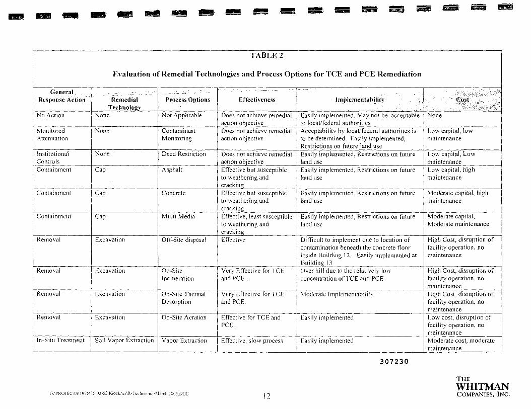
TABLE 2
Evaluation of Remedial Technologies and Process Options for TCE and PCE Remediation
General .Response Action
No Action
MonitoredAttenuation
InstitutionalControlsContainment
Containment
Containment
Removal
Removal
Removal
Removal
In-Situ Treatment
RemedialTechnology
None
None
None
Cap
Cap
Cap
Excavation
Excavation
Excavation
Excavation
Soil Vapor Extraction
Process Options
Not Applicable
ContaminantMonitoring
Deed Restriction
Asphalt
Concrete
Multi Media
Off-Site disposal
On-SiteIncineration
On-Site ThermalDesorption
On-Site Aeration
Vapor Extraction
Effectiveness
Does not achieve remedialaction objectiveDoes not achieve remedialaction objective
Does not achieve remedialaction objectiveEffective but susceptibleto weathering andcrackingEffective but susceptibleto weathering andcrackingEffective, least susceptibleto weathering andcrackingEffective
Very Effective for TCEand PCE .
Very Effective for TCEand PCE.
Effective for TCE andPCE.
Effective, slow process
Implementabiiify ;
Easily implemented, May not be acceptableto local/federal authoritiesAcceptability by local/federal authorities isto be determined. Easily implemented,Restrictions on future land useEasily implemented. Restrictions on futureland useEasily implemented, Restrictions on futureland use
Easily implemented, Restrictions on futureland use
Easily implemented, Restrictions on futureland use
Difficult to implement due to location ofcontamination beneath the concrete floorinside Building 12. Easily implemented atBuildingJSOver k i l l due to the relatively lowconcentration of TCE and PCE
Moderate Implementabil i ty
Easily implemented
Easily implemented
• • ' . ' * ' ' - Cost ,,*• ••',•' •• • ' *None
Low capital, lowmaintenance
Low capital, LowmaintenanceLow capital, highmaintenance
Moderate capital, highmaintenance
Moderate capital,Moderate maintenance
High Cost, disruption offacility operation, nomaintenance
High Cost, disruption offacility operation, nomaintenanceHigh Cost, disruption offacility operation, nomaintenanceLow cost, disruption offacility operation, nomaintenanceModerate cost, moderatemaintenance
307230
C:\PKOJECTS\1995\95-03-02 Klockner\R-Teclimc-ino-Marcli2005.DOC 12
THEWHITMANCOMPANIES, INC.

TABLE 2
Evaluation of Remedial Technologies and Process Options for TCE and PCE Remediation
General .;Response Action
In-Situ Treatment
In-Situ Treatment
In-situ-Treatment
In-situ-Treatment
In-si tuBioremediation
In situRemediationChemicalTreatment
ChemicalTreatment
Remedial'Technology
Thermal Extraction
Thermal Extraction
Thermal Extraction
Thermal Extraction
Bioremediation
Phytoremediation
In-situ ChemicalTreatment
In-situ ChemicalTreatment
Process Options
Steam injectioncombined withvapor extractionHot air injectioncombined withvapor extractionElectricalresistance heatingwith soil vaporextractionRadio-frequencyheating with soilvapor extractionAerobic oranaerobicmicrobialbiodegradationGrow poplar trees
Ozone injection
Hydrogen peroxideinjection
Effectiveness
Effective, slow process
Effective, slow process
Moderately effective,moderate process
Moderately effective, slowprocess
Moderately Effective,slow process
Slow process
Low effectiveness due tothe impermeability of thesoilLow effectiveness due tothe impermeability of thesoil
Implerhentability
Moderate Implementability
Difficult to Implement
Moderate Implementability
Moderate Implementability
Moderate Implementability
Easily implemented, Restrictions on futureland useDifficult to implement
Difficult to implement
'^oft0; - . . - • ' • '
L . ' " '- . '• f-:' -^a,, . •&-••". w ;,, '.,Moderate cost, moderatemaintenance
High Cost, moderatemaintenance
Moderate cost, moderatemaintenance
Moderate cost, moderatemaintenance
Low cost
Low capital, highmaintenanceModerate cost, highmaintenance
Moderate cost highmaintenance
307231
G:\PROJECTS\1995W5-01-02 Klockner\R-Techmemo-Marcli2005.DOC
THEWHITMANCOMPANIES, INC.

TABLE 3
Evaluation of Remedial Technologies and Process Options for Lead Remediation
General ResponseAction
No Action
Institutional Controls
Containment
Containment
Containment
Removal
Removal
In si tu Remediation
RemedialTechnology
None
None
Cap
Cap
Cap
Excavation
Excavation
Phytoremediation
Process Options
Not Applicable
Deed Restriction
Asphalt
Concrete
Multi Media
Ex-situ soilwashing
Off Site disposal
Grow poplar trees
Effectiveness
Does not achieve remedialaction objective
Does not achieve remedialaction objectiveEffective but susceptible toweathering and crackingEffective but susceptible toweathering and crackingEffective, least susceptible toweathering and crackingEffective
Effective
Slow process
Implementability
Easily implemented, May not beacceptable to local/federalauthoritiesDoes not achieve remedial actionobjectiveEasily implemented, Restrictionson future land useEasily implemented, Restrictionson future land useEasily implemented, Restrictionson future land useDifficult to implement given thearea required and restraints of thepropertyEasily Implemented, The Leadcontamination is confined to arelatively small area of the parkinglot.Easily implemented, Restrictionson future land use
'/•
Cost
None
Low capital, low maintenance
Low capital, high maintenance
Moderate capital, highmaintenanceModerate capital, ModeratemaintenanceModerate to high costdepending on quantity of soilto be treatedLow to Moderate cost
Low capital, high maintenance
307232
U:\PROJECTS\I995\95-03-02 Klockner\R-Techinemo-March2005.DOC
THEWHITMANCOMPANIES, INC.

II
1I1IIIIIItIIIII!IIII
iI11
5.3 Description of Seriously Considered Remedial Technologies
A preliminary evaluation of remedial technologies follows. The technologies evaluated
include presumptive remedies. Where available, initial cost information is provided. Only the
seriously considered remedial technologies are discussed in detail.
Soil vapor extraction (SVE), thermal desorption, and incineration are the presumptive
remedies at Superfund sites with soils contaminated with halogenated volatile organic
compounds (VOCs). Because a presumptive remedy is a technology that EPA believes, based
upon its past experience, generally will be the most appropriate remedy for a specified type of
site, the presumptive remedy approach will accelerate site-specific analysis of remedies by
focusing the feasibility study efforts.
SVE is the EPA preferred presumptive remedy. SVE has been selected most frequently to
address VOC contamination at Superfund sites, and performance data indicate that it effectivelytreats waste in place at a relatively low cost. In cases where SVE will not work or where
uncertainty exists regarding the ability to obtain required cleanup levels, thermal desorptionmay be the most appropriate response technology. In a limited number of situations.incineration may be most appropriate.
The following technologies included in Tables 2 and 3 are not included in the descriptions
presented below as they are not being seriously considered based on the site conditions and costsas identified in Tables 2 and 3:
• Excavation with On-site Incineration
• Excavation with On-site Thermal Desorption
• Excavation with On-site Soil Aeration
• Ex-situ Soil Washing
5.3.1 No Action
5.3.1.1 Description
Under the no action alternative, the remediation of the contaminated soils at the Klockner
& Klockner property portion of Operable Unit #3 would end. There would be no reduction in the
toxicity, and volume of contamination. Evaluation of the no action alternative is required under
by EPA, as it provides a baseline against which impacts of other alternatives can be compared.
307233
THEWHITMAN
G:\PROJECTS\1995\95-03-02Klockiier\R-Techmeino-Marcli2005.DOC 1 c COMPANIES, INC.

I
5.3.1.2 Applicability
No Action alternative is applicable for TCE. PCE and Lead soil contamination.
5.3.1.3 Limitations
The no action alternative could expose humans and the environment to contaminated soil and
ground water. Under this alternative, there would be no remediation, monitoring, or controls over
the contaminated site. Although unlikely, exposure could occur in the following ways:
• Migration of the contamination to ground water
• Migration of contaminant to off-site location
• Vapor intrusion from contaminated soil and ground water
5.3.1.4 Data Needs
Data requirements include the area and depth of contamination, the concentration of the
contaminants, depth to water table, and soil type and properties (e.g., structure, texture,permeability, and moisture content).
5.3.1.5 Performance Data
No action alternative is implemented in situations where the concentration of thecontaminant is very low and the potential for migration is low.
5.3.1.6 Cost
This is the lowest cost alternative as no action is required for remediation.
5.3.2 Monitored Natural Attenuation
5.3.2.1 Description
Monitored natural attenuation (MNA) allows the toxicity of the contaminant to be reduced
by a combination of various physical, chemical and biological processes taking place in the
contaminated environment. These processes include biodegradation. volatilization and migration
of the contaminant.
5.3.2.2 Applicability
MNA is applicable for TCE and PCE soil contamination. MNA is not applicable for Lead
soil contamination. 307234
THEWHITMAN
G:\PROJECTS\1995\95-03-02Klockner\R-Techmemo-March2005.DOC 1 £. COMPANIES, INC.

5.3.2.3 Limitations
lam'• MNA decreases the toxicity and volume of the TCE and PCE due to degradation, slow
volatilization and migration. The volume of lead contamination is not reduced by MNA as it
Jl does not biodegrade or volatilize. Toxicity due to lead is not reduced due to relatively slow
migration and dilution through the clayey silt. A restriction on future land use would be required
II until remediation goals are met.
n 5.3.2.4 Data Needs
IIData requirements include the area and depth of contamination, the concentration of the
H contaminants, depth to water table, and soil type and properties (e.g., nutrients, structure, texture,
permeability, and moisture content).
|| 5.3.2.5 Performance Data
B MNA is readily implemented and successfully used especially in combination with other
Engineering and Institutional Controls.
|| 5.3.2.6 Cost
HI MNA is a relatively low cost alternative, with monitoring of the contaminant being a major
HI cost factor.
H 5.3.3 Institutional Control
m 5.3.3.1 Description
Institutional controls are designed to reduce exposure to toxic chemicals and protect human
• health by restricting land use. The most common institutional control is a restrictive covenant in
B the form of deed notice.
• 5.3.3.2 Applicability
m Institutional Controls is applicable for TCE, PCE and Lead soil contamination.
5.3.3.3 Limitations
•» Institutional controls do not reduce the toxicity, mobil i ty or the volume of the contaminant.
A deed notice would specify any requirements for monitoring, maintenance of potential
H 307235THE
m WHITMAN• G:\PROjrcTS\1995W5-O.V02Klocknei\R-Techmemo-March2005.DOC | -j COMPANIES, INC.

II
0
I
engineering controls and restrictions on property use to prevent the dispersion of or exposure to
any contaminated soil. Restrictive covenants would also require notification of the presence of
soil contamination and can be long term.
5.3.3.4 Data Needs
Data requirements include the area and depth of contamination, the concentration of the
contaminants, depth to water table, and soil type and properties (e.g., structure, texture,
permeability, and moisture content).
5.3.3.5 Performance Data
Institutional controls are readily available and have been successfully used.
5.3.3.6 Cost
The cost of imposing Institutional Controls is low to moderate as they involve long termmonitoring and legal and administrative costs.
5.3.4 Capping/Containment
5.3.4.1 Description
Capping is a common form of remediation because it is generally less expensive than other
technologies and effectively manages the human and ecological risks associated with a
remediation site. The most common caps are Asphalt, Concrete and Multi Media.
The most effective single-layer caps are composed of concrete or bituminous asphalt. It isused to form a surface barrier between contaminated soil and the environment. An asphalt or
concrete cap would reduce leaching through the soil into an adjacent aquifer.
5.3.4.2 Applicability
Caps may be applied to contaminated soil that is so large that other treatment is
impractical. The cap can be used to minimize the infiltration of water through contaminated soil
and the migration of contaminants into the ground water. In conjunction with water diversion
and detention structures, caps may be designed to route surface water away from the
contaminated soil. Capping is applicable for TCE, PCE and Lead soil contamination. As a
majority of the contaminants are already under the foot print of the building, it is already capped.
The remaining area outside the building can be easily capped to prevent migration of the
contaminants. 307236
THEWHITMAN
G:\PROJECTS\ig95\95-03-02Klockner\R-Techmemo-Marcli2005.DOC 10 COMPANIES, INC.

II
II
II
II
I
II
I
I
I
I
I
5.3.4.3 Limitations
Capping does not lessen toxicity, mobility, or volume of the contaminant, but does
mitigate migration and exposure. Caps are most effective where most of the underlying
contaminant is above the water table. A cap, by itself, cannot prevent the horizontal flow of
ground water through the waste, only the vertical entry of water into the waste. Caps can be used
in conjunction with vertical walls to minimize horizontal flow and migration. Caps are
susceptible to weathering and cracking. Therefore, the effective life of a cap can be extended by
long-term inspection and maintenance. Precautions must be taken to assume that the integrity of
the cap is not compromised by land use activities. A restriction on future land use would be
required.
5.3.4.4 Data Needs
Data requirements include the area and depth of contamination, the concentration of the
contaminants, condition and type of existing cover (e.g. asphalt, concrete soil), depth to water
table, and soil type and properties (e.g., structure, texture, permeability, and moisture content).
5.3.4.5 Performance Data
Previously installed caps are hard to monitor for performance. Monitoring well systems or
infiltration monitoring systems can provide some information, but it is often not possible to
determine the source of the contaminant. Caps are often installed to prevent, or significantly
reduce, the migration of contaminants in soils or ground water. Containment is necessary
whenever contaminated materials are to be buried or left in place at a site. In general,containment is performed when extensive subsurface contamination at a site precludesexcavation and removal of wastes because of potential hazards, unrealistic cost, or lack of
adequate treatment technologies.
5.3.4.6 Cost
Containment treatment such as caps offer quick installation times and are typically a low to
moderate cost treatment group. Unlike ex situ treatment groups, containment does not require
excavation of soils that lead to increased costs from engineering design of equipment, possible
permitting, and material handling. However, capping requires periodic inspections. Additionally,
ground water monitoring wells, associated with the treatments, may need to be periodically
sampled and maintained. Even with these long-term requirements, containment treatments
usually are considerably more economical than excavation and removal of the wastes.
307237
THEWHITMAN
G-APROJECTS\1995W5-O.V02Klockner\R-Tcchmemo-March2005.DOC in COMPANIES, INC.

I!
II1:
1
1
1
1
1
I
I
I
5.3.5 Excavation, Retrieval, and Off-Site Disposal
5.3.5.1 Description
Contaminated material is removed and transported to permitted off-site treatment and/or
disposal facilities. Some pretreatment of the contaminated media usually is required in order to
meet land disposal restrictions.
Confined disposal facilities (CDFs) are engineered structures enclosed by dikes and
designed to retain disposed materials. A CDF may have a large cell for material disposal, and
adjoining cells for retention and decantation of turbid, supernatant water. A variety of linings
have been used to prevent seepage through the dike walls. The most effective are clay or
bentonite-cement slurries, but sand, soil, and sediment linings have also been used.
Operation and maintenance duration lasts as long as the life of the facility.
5.3.5.2 Applicability
Excavation and off-site disposal is applicable to the complete range of contaminant groupswith no particular target group. Therefore, it is applicable for TCE, PCE and Lead soil
contamination. Excavation and off-site disposal by relocating the waste to a different (and
presumably safer) site.
5.3.5.3 Limitations
Factors that may limit the applicability and effectiveness of the process include:
• Generation of fugitive emissions may be a problem during operations.
« The distance from the contaminated site to the nearest disposal facility with the
required permit(s) will affect cost.
o Depth and composition of the media requiring excavation must be considered.
•> Transportation of the soil through populated areas may affect community acceptability.
» Accessibility of the contaminated area to excavation under the site specific conditions.
5.3.5.4 Data Needs
Data requirements include the area and depth of contamination, the concentration of the
contaminants, depth to water table, and soil type.307238
THEWHITMAN
G:\PROJECTS\l995W5-03-02Klockner\R-Techmcmo-Marcli2005.DOC 2Q COMPANIES, INC.

II
II
II
5.3.5.5 Performance Data
Excavation and off-site disposal is a well proven and readily implementable technology.
Prior to 1984. excavation and off-site disposal was the most common method for cleaning up
hazardous waste sites. Excavation is the initial component in all ex situ treatments.
CERCLA includes a statutory preference for treatment of contaminants, and excavation
and off-site disposal is now less acceptable than in the past. The disposal of hazardous wastes isgoverned by RCRA (40 CFR Parts 261-265), and the U.S. Department of Transportation (DOT)
regulates the transport of hazardous materials (49 CFR Parts 172-179, 49 CFR Part 1387, and
DOT-E 8876).
5.3.5.6 Cost
Cost estimates for excavation and disposal range from $300 to $510 per metric ton ($270to $460 per ton). These estimates include excavation/removal, transportation, and disposal at aRCRA permitted facility. Additional cost of treatment at disposal facility may also be required.Excavation and off-site disposal is a relatively simple process, with proven procedures. It is alabor-intensive practice with little potential for further automation. Additional costs may includesoil characterization and treatment to meet land ban requirements.
5.3.6 Soil Vapor Extraction
A vacuum is applied through extraction wells to create a pressure/concentration gradient
that induces gas-phase volatiles to be removed from soil through extraction wells. Thistechnology also is known as in situ soil venting, in situ volatilization, enhanced volatilization, orsoil vacuum extraction.
I
I
I
1
307239
G:\PROJECTS\1995\95-03-02 Klockner\R-Techinemo-Marcli2005.DOC 21
THEWHITMANCOMPANIES, INC.

i Typical In Situ Soil Vapor Extraction System
1
It
Hlini
Vacuum Relief Valve
Moisture Separator Inlet
MoistureSeparator^
ir Fitter
Manual Starter forHazardous Locations
High LevelInlet AirShut-Off Float
SVE is an in situ unsaturated (vadose) zone soil remediation technology in which avacuum is applied to the soil to induce the controlled flow of air and remove volatile and somesemivolatile contaminants from the soil. The gas leaving the soil may be treated to recover ordestroy the contaminants, depending on local and state air discharge regulations. Verticalextraction vents are typically used at depths of 1.5 meters (5 feet) or greater. Horizontalextraction vents (installed in trenches or horizontal borings) can be used as warranted bycontaminant zone geometry, drill rig access, or other site-specific factors.
Ground water depression pumps may be used to reduce ground water upwelling inducedby the vacuum or to increase the depth of the vadose zone. Air injection is effective forfacilitating extraction of deep contamination, contamination in low permeability soils, and
contamination in the saturated zone. The duration of operation and maintenance for in situ SVE
is typically 1 to 3 years. 307240
G:\PROJECTS\1995\95-03-02 Klockner\R-Techtncmo-March2005.DOC 22
THEWHITMANCOMPANIES, INC.

5.3.6.1 Applicability
The target contaminant groups for in situ SVE are VOCs and some fuels. The technology
is typically applicable only to volatile compounds with a Henry's law constant greater than 0.01
or a vapor pressure greater than 0.5 mm Hg (0.02 inches Hg). Vapor Pressure for TCE is 58 mm
of Hg, and for PCE it is 18.47 mm of Hg. making them good candidates for the process. SVE is
not applicable to Lead. Other factors, such as the moisture content, organic content, and air
permeability of the soil, also will impact the effectiveness of in situ SVE. Because the process
involves the continuous flow of air through the soil, however, it often promotes the in situ
biodegradation of low-volatility organic compounds that may be present.
5.3.6.2 Limitations
Factors that may limit the applicability and effectiveness of the process include:
• Soil that has a high percentage of fines and a high degree of saturation will require
higher vacuums (increasing costs) and/or will hinder the operation of the in situ SVEsystem.
• Large screened intervals are required in extraction wells for soil with highly variablepermeabilities or stratification, which otherwise may result in uneven delivery of gas
flow from the contaminated regions.
• Soil that has high organic content or is extremely dry has a high sorption capacity ofVOCs, which results in reduced removal rates.
• Exhaust air from in situ SVE system may require treatment to eliminate possible harmto the public and the environment.
• As a result of off-gas treatment, residual liquids may require treatment/disposal. Spentactivated carbon definitely will require regeneration or disposal.
» SVE is not effective in the saturated zone.
5.3.6.3 Data Needs
Data requirements include the area and depth of contamination, the concentration of the
contaminants, depth to water table, and soil type and properties (e.g.. structure, texture,
permeability, and moisture content).
Pilot studies should be performed to provide design information, including extraction well,
radius of influence, gas flow rates, optimal applied vacuum, and contaminant mass removal
rates. 307241
I
THEWHITMAN
G:\PROJECTS\l995\95-03-02Klockner\R-Tcchmemo-March2005.DOC 23 COMPANIES, INC.

5.3.6.4 Performance Data
A field pilot study is necessary to establish the feasibility of the method as well as to obtain
information necessary to design and configure the system. During full-scale operation, in situ
SVE can be operated intermittently (pulsed operation) once the extracted mass removal rate has
reached an asymptotic level. This pulsed operation can increase the cost-effectiveness of the
system by facilitating extraction of higher concentrations of contaminants. After the
contaminants are removed by in situ SVE, other remedial measures, such as biodegradation or
engineering controls, can be investigated if remedial action objectives have not been met. In situ
SVE projects are typically completed in 1 to 3 years.
5.3.6.5 Cost
The cost of in situ SVE is site-specific, depending on the size of the site, the nature and
amount of contamination, and the hydrogeological setting (EPA, July 1989). These factors affect
the number of wells, the blower capacity and vacuum level required, and the length of timerequired to remediate the site. A requirement for off-gas treatment adds significantly to the cost.
Water is also frequently extracted during the process and usually requires treatment prior todisposal, further adding to the cost. Cost estimates for in situ SVE range between $10 and $50
per cubic meter ($10 and $40 per cubic yard) of soil. Pilot testing typically costs $10,000 to
$40.000.
I!III1IIII
5.3.7 In Situ Thermal Treatment
In situ thermal treatment is a full-scale technology that uses electrical
resistance/electromagnetic/fiber optic/radio frequency heating or hot-air/steam injection toincrease the volatilization rate of semi-volatiles and volatiles and facilitate extraction. The
volatilized contaminants are collected by SVE. These technologies are discussed below.
307242
G:\PROJECTSM995\95-03-02 KlockncrtR-Techmemo-March 2005.DOC 24
THEWHITMANCOMPANIES, INC.

Typical Six-Phase Soil Heating System
ElectricallyHeatedRegion
II
I!II
11II
Typical Hot Air System
Vent GasVent GasCollectionChannels
,LA A AA
Burn er/Blower
A A lAA A A
« tf ^ _ - , -;ContaminatedJZone ' i
^ i r » * • * • " * « i*** **^ **s
CD© (fifljOff-Gas Collection
A A
Hot Air/Steam Inj ection Wells
307243
AA
G:\PROJECTS\I995\95-03-02 Klockner\R-Techmcmo-March2005.DOC 25
THEWHITMANCOMPANIES, INC.

U The process is otherwise similar to standard SVE, but requires heat resistant extraction
wells. In situ thermal treatment with SVE is normally a short- to medium-term technology.
5.3.7.1 Electrical Resistance Heating
H Electrical resistance heating uses an electrical current to heat less permeable soils such as
clays and fine-grained sediments so that water and contaminants trapped in these relatively
H conductive regions are vaporized and ready for vacuum extraction. Electrodes are placed directly
into the less permeable soil matrix and activated so that electrical current passes through the soil,
In creating a resistance, which then heats the soil. The heat dries out the soil causing it to fracture.
1 These fractures make the soil more permeable allowing the use of SVE to remove thecontaminants. The heat created by electrical resistance heating also forces trapped liquids to
11 vaporize and move to the steam zone for removal by SVE. Six-phase soil heating (SPSH) is a
typical electrical resistance heating which uses low-frequency electricity delivered to six
IB electrodes in a circular array to heat soils. With SPSH, the temperature of the soil and
I contaminant is increased, thereby increasing the contaminant's vapor pressure and its removal
rate. SPSH also creates an in situ source of steam to strip contaminants from soil. At this time
III SPSH is in the demonstration phase, and all large scale in situ projects utilize three-phase soilheating.
II
I
I
1
I
I
5.3.7.2 Radio Frequency/Electromagnetic Heating
Radio frequency heating (RFH) is an in situ process that uses electromagnetic energy to
heat soil and enhance SVE. The RFH technique heats a discrete volume of soil using rows ofvertical electrodes embedded in soil (or other media). Heated soil volumes are bounded by two
rows of ground electrodes with energy applied to a third row midway between the ground rows.The three rows act as a buried triplate capacitor. When energy is applied to the electrode array,
heating begins at the top center and proceeds vertically downward and laterally outward throughthe soil volume. The technique can heat soils to over 300 °C.
RFH enhances SVE in four ways: (1) contaminant vapor pressure and diffusivity areincreased by heating, (2) the soil permeability is increased by drying, (3) an increase in the
volatility of the contaminant from in situ steam stripping by the water vapor, and (4) a decrease
in the viscosity which improves mobility. The technology is self limiting; as the soil heats and
dries, current will stop flowing. Extracted vapor can then be treated by a variety of existing
technologies, such as granular activated carbon or incineration.
307244
THEWHITMAN
G:\PROJECTS\1995\95-03-02 Klockner\R-Techincnio-Marcli2005.DOC COMPANIES, INC.

1
II
II
5.3.7.3 Hot Air/Steam Injection
Hot air or steam is injected below the contaminated zone to heat up contaminated soil. The
heating enhances the release of contaminants from the soil matrix. Some VOCs and SVOCs are
stripped from the contaminated zone and brought to the surface through SVE.
5.3.7.4 Applicability
High moisture content is a limitation of standard SVE that thermal enhancement may helpovercome. Heating, especially radio frequency heating and electrical resistance heating canimprove air flow in high moisture soils by evaporating water. The system is designed to treatsemivolatiles but will consequently treat volatiles. In situ thermal treatment is not applicable toLead. After application of this process, subsurface conditions are excellent for biodegradation of
residual contaminants.
5.3.7.5 LimitationsIIII The following factors may limit the applicability and effectiveness of the process:
mm
Debris or other large objects buried in the media can cause operating difficulties.Performance in extracting certain contaminants varies depending upon the maximumtemperature achieved in the process selected.Soil that is tight or has high moisture content has a reduced permeability to air.hindering the operation of thermally enhanced SVE and requiring more energy input toincrease vacuum and temperature.Soil with highly variable permeabilities may result in uneven delivery of gas flow tothe contaminated regions.Soil that has a high organic content has a high sorption capacity of VOCs, whichresults in reduced removal rates.Air emissions may need to be regulated to eliminate possible harm to the public and theenvironment. Air treatment and permitting will increase project costs.Residual liquids and spent activated carbon may require further treatment.Thermally enhanced SVE is not effective in the saturated zone; however, lowering the
aquifer can expose more media to SVE.Hot air injection has limitations due to low heat capacity of air.
Difficulty in controlling the direction of the steam/hot air migration through the
shallow silty clay.
307245
THEWHITMAN
G:\PROJECTS\1995\95-03-02Klockner\R-Techinemo-March2005.DOC 27 COMPANIES, INC.
5.3.7.6 Data Needs
Data requirements include the area and depth of contamination, the concentration of thecontaminants, depth to water table, and soil type and properties (e.g., structure, texture,
permeability, and moisture content).
Pilot studies should be performed to provide design information, including extraction well,
radius of influence, gas flow rates, optimal applied vacuum, optimal heat injection andcontaminant mass removal rates.
5.3.7.7 Performance Data
Thermal Treatment has been used for the remediation of solvent contaminated soils. Itssuccess will depend on the soil and sight conditions. A field pilot study is necessary to establishthe feasibility of the method as well as to obtain information necessary to design and configurethe system. After the contaminants are removed by in situ thermal treatment, other remedialmeasures, such as biodegradation or engineering controls, can be investigated if remedial actionobjectives have not been met.
5.3.7.8 Cost
Available data indicate the overall cost for thermally enhanced SVE systems isapproximately $30 to $130 per cubic meter ($25 to $100 per cubic yard).
5.3.8 In-Situ Bioremediation
5.3.8.1 Description
During in-situ bioremediation, the activity of naturally occurring microbes is stimulated bycirculating water-based solutions through contaminated soils to enhance in-situ biologicalremediation of organic contaminants. Nutrients, oxygen, or other amendments may be used toenhance bioremediation and contaminant desorption from subsurface materials. Generally, the
process includes above-ground treatment and conditioning of the infiltration water with nutrientsand an oxygen (or other electron acceptor) source. In-situ bioremediation is a full-scale
technology.
5.3.8.2 Applicability
Target contaminants for in-situ bioremediation are non-halogenated VOCs and SVOCs.
and fuel hydrocarbons. Halogenated VOCs and SVOCs also can be treated, but the process may
307246
THEWHITMAN
G:\PROJECTS\l995W5-03-02Klocknei\R-Techmemo-March2005.DOC 90 COMPANIES, INC.

1
II
1
I
I
I
be less effective and may only be applicable to some compounds within these contaminant
groups. In-situ bioremediation is not applicable to Lead.
5.3.8.3 Limitations
The following factors may limit the applicability and effectiveness of this process:
• Extensive treatability studies and site characterization may be necessary.
• The circulation of water-based solutions through the soil may increase contaminant
mobility.
« The injection of microorganisms into the subsurface is not recommended. Naturallyoccurring organisms are generally adapted to the contaminants present.
o Preferential flow paths may severely decrease contact between injected fluids and
contaminants throughout the contaminated zones.
• The system should be used only where ground water is near the surface and where theground water underlying the contaminated soils is contaminated.
• The system should not be used for clay, highly layered, or heterogeneous subsurfaceenvironments due to oxygen (or other electron acceptor) transfer limitations.
• Bioremediation may not be applicable at sites with high concentrations of heavymetals, highly chlorinated organics, or inorganic salts.
5.3.8.4 Data Needs
Data requirements include the area and depth of contamination, the concentration of the
contaminants, type of microorganisms present and soil type and properties (e.g., nutrients,structure, texture, permeability, and moisture content).
Bench scale and/or pilot studies should be performed to provide design information,including nutrient requirements and contaminant mass removal rates.
5.3.8.5 Performance Data
Bioremediation has been successfully used for the treatment of Chlorinated solventcontaminated soil. The success of the process may be limited by the clay content of the soil,ability to create anaerobic conditions and ability to deliver nutrients to the contaminated areas.
5.3.8.6 Cost
In-situ Bioremediation is a moderate cost alternative.
307247
THEWHITMAN
G:\PROJECTSU995\95-03-02KlockncrVR-Techmemo-March2005.DOC 29 COMPANIES, INC.

1II
IHSiII
B
5.3.9 Phytoremediation
5.3.9.1 Description of Phytoremediation
Phytoremediation is a process that uses plants to remove, transfer, stabilize, and destroy
contaminants in soil and sediment. The mechanisms of phytoremediation include enhanced
rhizosphere biodegradation, phyto-extraction (also called phyto-accumulation). phyto-
degradation. and phyto-stabilization.
5.3.9.2 Enhanced Rhizosphere Biodegradation
Enhanced rhizosphere biodegradation takes place in the soil immediately surrounding plant
roots. Natural substances released by plant roots supply nutrients to microorganisms, which
enhances their biological activities. Plant roots also loosen the soil and then die, leaving paths fortransport of water and aeration. This process tends to pull water to the surface zone and dry the
lower saturated zones.
The most commonly used flora in phytoremediation projects are poplar trees, primarily
because the trees are fast growing and can survive in a broad range of climates. In addition,popkir trees can draw large amounts of water (relative to other plant species) as it passes through
soil or directly from an aquifer. This may draw greater amounts of dissolved pollutants fromcontaminated media and reduce the amount of water that may pass through soil or an aquifer,
thereby reducing the amount of contaminant flushed through or out of the soil or aquifer.
5.3.9.3 Phyto-accumulation
Phyto-accumulation is the uptake of contaminants by plant roots and thetranslocation/accumulation (phytoextraction) of contaminants into plant shoots and leaves.
5.3.9.4 Phyto-degradation
Phyto-degradation is the metabolism of contaminants within plant tissues. Plants produce
enzymes, such as dehalogenase and oxygenase that help catalyze degradation. Investigations are
proceeding to determine if both aromatic and chlorinated aliphatic compounds are amenable to
phyto-degradation.
5.3.9.5 Phyto-stabilization
Phyto-stabilization is the phenomenon of production of chemical compounds by plants to
immobilize contaminants at the interface of roots and soil.307248
THEWHITMAN
G-\PROJECTS\1W5\95-03-02 Klockner\R-Techmemo-March2005.DOC COMPANIES, INC.

5.3.9.6 Applicability
GIIniiiiiiiii
Phytoremediation is applicable for the remediation of metals such as Lead and solvents
including TCE and PCE.
Some plant species have the ability to store metals in their roots. They can be transplanted
to sites to filter metals from wastewater. As the roots become saturated with metal contaminants,
they can be harvested.
Hyper-accumulator plants may be able to remove and store significant amounts of metallic
contaminants.
Currently, trees are under investigation to determine their ability to remove organic
contaminants from ground water, translocate and transpiration, and possibly metabolize them
either to COj or plant tissue.
5.3.9.7 Limitations
Limitations to phytoremediation in soil at the subject site include:
• The depth of the treatment zone is determined by plants used in phytoremediation. Inmost cases, it is limited to shallow soils.
• High concentrations of hazardous materials can be toxic to plants.
• It involves the same mass transfer limitations as other biotreatments.• It may be seasonal, depending on location.
• Access. A majority of the contamination area is under the footprint of the building,under 12" of concrete slab.
• It can transfer contamination across media, e.g., from soil to air.• It is not effective for strongly sorbed (e.g., PCBs) and weakly sorbed contaminants.
• The toxicity and bioavailability of biodegradation products is not always known.
« It is still in the demonstration stage.
o It is unfamiliar to regulators.
307249
G:\PROJECTS\I995\95-0.1-02 Klockner\R-Teclimemo-March2005.DOC
THEWHITMANCOMPANIES, INC.

II
5.3.9.8 Data Needs
Detailed information is needed to determine the kinds of soil used for phytoremediation
projects. Water movement, reductive oxygen concentrations, root growth, and root structure all
affect the growth of plants and should be considered when implementing phytoremediation.
5.3.9.9 Cost
Available data indicate the overall cost for phytoremediation is moderate.
5.3.10 In-situ Chemical Oxidation
5.3.10.1 Description
Highly effective ozone generating systems have been designed to destroy the contaminantsPCE and TCE in situ. It has long been known that ozone is an extremely effective chemical
oxidizer and much data has been published indicating the effectiveness of ozone for treatingPCE. TCE, vinyl chloride, DCE, and other chlorinated solvents. Several projects conducted in
the State of Florida at dry cleaning facilities have demonstrated the potential for ozone to cleanup PCE and TCE contaminated sites.
5.3.10.2 Applicability
The target contaminant group for oxidation/reduction is inorganics. The technology can be
used as well to treat halogenated VOCs, but may be less effective for those contaminants.Oxidation/reduction is a well-established technology used for disinfecting drinking water and
wastewater. and is a common treatment for cyanide wastes. Enhanced systems are now beingused more frequently to treat hazardous wastes in soils.
In situ chemical oxidation using ozone generation system offers a number of significant
advantages for on-site remediation, including:
• Potential for complete destruction of PCE and TCE without the formation of harmful
byproducts
• Low operating costs
• PCE, TCE and other chlorinated solvents are treated in one system
In situ oxidation is not applicable to Lead as it is an element.
307250
THEWHITMAN
G:\PROJECTS\1995\95-03-02 Klocknei\R-Techmemo-March2005.DOC - ) COMPANIES, INC.

1
1
1
5.3.10.3 Limitations
The following factors may limit the applicability and effectiveness of this process:
• Potential for incomplete oxidation or formation of intermediate contaminants that are
more toxic than the original contaminants may occur depending upon the contaminants
and oxidizing agents used. (The CVOCs of concern are readily oxidized with any
potential intermediates being short lived and readily oxidized themselves.)
• The process is not cost-effective for highly contaminated materials due to the large
amounts of oxidizing/reducing agents required.
• The chemicals used in oxidation/reduction pose a potential health and safety risk to
site workers through skin contact and air emissions. Personal protective equipment, at alevel commensurate with the contaminants involved, is normally required during
treatment operations.
5.3.10.4 Data Needs
Engineering of in situ chemical oxidation must be done with due attention paid to reaction
chemistry and transport processes. It is also critical that close attention be paid to worker trainingand safe handling of process chemicals as well as proper management of remediation wastes.
The design and implementation process should rely on an integrated effort involving screening
level characterization tests and reaction transport modeling, combined with treatability studies atthe lab and field scale.
5.3.10.5 Performance Data
In situ chemical oxidation is a viable remediation technology for mass reduction in sourceareas as well as for plume treatment. The potential benefits of in situ oxidation include the rapidand extensive reactions with various COCs applicable to many bio-recalcitrant organics and
subsurface environments. Also, in situ chemical oxidation can be tailored to a site and
implemented with relatively simple, readily available equipment. Some potential limitations exist
including the requirement for handling large quantities of hazardous oxidizing chemicals due to
the oxidant demand of the target organic chemicals and the unproductive oxidant consumption of
the formation; some COCs are resistant to oxidation; and there is a potential for process-induced
detrimental effects. Further research and development is ongoing to advance the science and
engineering of in situ chemical oxidation and to increase its overall cost effectiveness
5.3.10.6 Cost307251
This is a high cost process option.
THEWHITMAN
G:\PROJECTS\1995W5-03-02 Klockner\R-Teclimemo-March2005.DOC -j-? COMPANIES, INC.

III!I!II1III
6.0 INITIAL SCREENING OF PROCESS OPTIONS
The purpose of this section is to review the initial list of process options and screen that listto eliminate those options that are not appropriate to Operable Unit #3 in accordance with thescreening criteria identified in the EPA guidance document Feasibility Study rule. Under theFeasibility Study rule, process options must be evaluated in terms of their effectiveness, cost,timeliness, and whether they are considered acceptable engineering practices given the option'sfeasibility for the location and reliability.
Whitman applied these regulatory criteria to the site-specific information such as geologicor hydrogeologic conditions and contaminant type and concentration. Published and personalaccounts of technology performance and professional judgment also were included in theevaluation process. Reasons for eliminating remedial technologies and process options arepresented in the following section and summarized in Table 4 for TCE and PCE and Table 5 forLead. Surviving options receive a more detailed review in section 7.0 of this document.
6.1 Eliminated Process Options
Several process options were eliminated prior to forming the preliminary remedialalternatives. The basis for elimination of each is described in Section 5.3 and Tables 4 and 5below. These process options are denoted with "no" in the final column of Tables 4 and 5.
1307252
1 G:\PROJIICTS\I995\95-03-02 KlocknertR-Tcchmemo-March 2005.DOC
THEWHITMANCOMPANIES, INC.

TABLE 4
Screening and Elimination of Process Options for TCE and PCE for Klockner Property
Process Options
No Action
Institutional Control
Monitored NaturalAttenuationCapping withAsphalt
Capping withConcrete
Capping with mul t imedia
Partial Excavation
Excavation with Off-site disposal
Excavation wi th On-site incineration
Excavation with On-site thermaldesorplion
Protection ofhuman health
and theenvironment
No
None to low
Moderate
Moderate tohigh
Moderate tohigh
Moderate
Moderate tohighHigh
Moderate tohigh
Moderate tohigh
Compliancewith ARARs
No
No
Yes
Partialcompliance
Partialcompliance
Partialcompliance
Yes
Yes
Yes
Yes
Long termeffectiveness
No
No
Yes
Moderate to high
Moderate to high
Moderate
Moderate to higheffectivenessHigh Effectiveness
Moderate to higheffectiveness
Moderate to higheffectiveness
Reduce thetoxicity, mobility,and volume of the
contamination
No
No
No
Slow reduction
Slow reduction
Slow reduction
Moderate to highreductionHigh Reduction
High reduction
High reduction
Short termeffectiveness
"
No
No
Moderate
Yes
Yes
Yes
Moderate to higheffectivenessVery Effective
Moderate to higheffectiveness
Moderate to higheffectiveness
rmplementability
V .' .,.-",,. -- ' '*;"*--
Iniplcmcntable
Implementable
Implementable
Implementable
Implementable
Notimplementable.Affects theindended use dueto altering theelevation of theareaImplementable
Disruption ofestablishedbusiness operation
Notimplementable dueto disruption ofestablishedbusinessNotimplementable duedisruption ofestablishedbusiness operation
CostEffectiveness
Yes
Yes
Yes
Cost effective
Cost effective
Cost effective
Cost effective
High cost
High cost
High cost
Stateacceptance
Notacceptable
NotacceptableAcceptable
Acceptable
Acceptable
Acceptable
Acceptable
Acceptable
Acceptable
Acceptable
Communityacceptance
Not Acceptable
Not Acceptable
Acceptable
Acceptable
Acceptable
Acceptable
Acceptable
Acceptable
Not Acceptable
Not Acceptable
Preliminaryremedial
"alternative^
Yes
Yes
Yes
Yes
Yes
No
Yes
No
No
No
307253
U:\PROJECTS\I995W5-03-02 Klockner\R-Techniemo-Marcli2005.DOC 35
THEWHITMANCOMPANIES, INC.

TABLE 4
Screening and Elimination of Process Options for TCE and PCE for Klockner Property
Process Options
Excavation with On-site soil aeration
SV1Z
Steam injection withSVE
Hot air injectionSVE
Radio frequencyheating with SVE
Electrical ResistanceHeating with SVE
In-si tu Chemicaltreatment withOzone
In-situ Chemicaltreatment withHydrogen peroxide
Bioremedialion
Phvtoremediation
Protection ofhuman health
and theenvironment; ,
Moderate tohigh
Moderate tohigh
Moderate tohigh
Moderate tohigh
Moderate tohigh
Moderate tohigh
Moderate tohigh
Moderate tohigh
Low tomoderateLow tomoderate
Compliancewith ARARs
_, . .-,...—,-. rr^fi1
Yes
Yes
Yes
Yes
Yes
Yes
Yes
Yes
Yes
Yes
Long termeffectiveness
;•-:--— -s-i'~< • • - •
Moderate to higheffectiveness
Moderate to higheffectiveness
Moderate to higheffectiveness
Moderate to higheffectiveness
Moderateeffectiveness
Moderateeffectiveness
High Cost
High Cost
Low to moderatecost
Low to moderatecost
Reduce thetoxicity, mobility,and volume of the.
- "-confarriihatioh
Moderate to highreduction
Moderate to highreduction
Moderate to highreduction
Moderate to highreduction
Moderate to highreduction
Moderate to highreduction
Moderate to highreduction
Moderate to highreduction
Low to moderatereduction
Low to moderatereduction
Short termeffectiveness
Moderate to higheffectiveness
Effective
Not Effectivedue to dif f icul tyin directingsteam throughsiltv clayNot Effectivedue to difficultyin directing hotair through siltyclavModeratelyeffective
Moderatelyeffective
Loweffectiveness
Loweffectiveness
Low to moderateeffectiveness
Low to moderateeffectiveness
Implcmentability
Notimplementablc dueto disruption ofestablishedbusiness operationImplementable
Implementabie
Implementable
Implementable
Implementable
LowImplementabil i ty
LowImplementabili ty
Implementable
Implementable
CostEffectiveness
Low cost
Low toModerate cost
Moderate tohigh cost
Moderate tohigh cost
High cost
High cost
High cost
High cost
Low tomoderate cost
Low tomoderate cost
State'acceptance
Acceptable
Acceptable
Acceptable
Acceptable
Acceptable
Acceptable
Acceptable
Acceptable
Acceptable
Acceptable
Communityacceptance^,,,.
Not Acceptable
Acceptable
Acceptable
Acceptable
Acceptable
Acceptable
Acceptable
Acceptable
Acceptable
Acceptable
Preliminaryjemedial",.-
alternative*"
No
Yes
No
No
No
No
No
No
No
No
307254
G:\PROJECTS\1995W5-03-02 KlockncrtR-Tecliniemo-Marcli 2005.DOC 36
THEWHITMANCOMPANIES, INC.

TABLE 5
Screening And Elimination Of Process Options For Lead for Klockner Property
Process options
No Action
Ins t i tu t iona l Control
Capping withAsphalt
Capping withConcrete
Capping with mu l t imedia
Phytorcmediation
II.x-sHu Soil Washing
Ifxcavation andoffsite disposal
Protectioirof'human health
and theenvironment
No
None to low
Moderate tohigh
Moderate tohigh
Moderate
Low tomoderate
Moderate tohighHigh
"Compliancewith ARARs
No
PartialcompliancePartialcompliance
Partialcompliance
Partialcompliance
Yes
Yes
Yes
Long termeffectiveness
No
No
Moderate to high
Moderate to high
Moderate
Yes
Yes
Yes
Reduce thetoxicity, mobility,and volume of the
contamination
No
No
Reduction inmobility only
Reduction inmobility only
Reduction inmobili ty only
Slow reduction
Yes
Yes
Short termeffectiveness
No
No
Yes
Yes
Yes
No
Yes
Yes
Implementability
Implementable
Implementable
Implementable
Implementable
Notimplementable.Affects theindended use dueto altering theelevation of theareaNotimplementable.Affects theindended use dueto altering theelevation of theareaNotimplementableImplementable
CostEffectiveness
Yes
Yes
Yes
Yes
Yes
No
No
Yes
State'acceptance
Notacceptable
NotacceptableAcceptable
Acceptable
Acceptable
Acceptable
Acceptable
Acceptable
Communityacceptance
Not Acceptable
Not Acceptable
Acceptable
Acceptable
Acceptable
Acceptable
Acceptable
Acceptable
Preliminaryremedial
alternative
Yes
Yes
Yes
No
No
No
No
Yes
307255
G:\PROJIZCTS\I995W5-03-02 Klockiier\R-Techineinn-Marcli2005.DOC 37
THEWHITMANCOMPANIES, INC.

IB
II
7.0 DETAILED ANALYSIS OF ALTERNATIVES
7.1 Description of Remedial Alternatives
Using the surviving process options, Whitman has developed an array of remedial
alternatives that can eliminate, reduce, or control the potential risks to human health and the
environment present at the Klockner Property. The remedial alternatives are combinations of the
surviving process options.
The following key site-specific conditions also were considered during development of the
Unit #3 alternatives:
• the distribution of TCE, PCE and Lead
• existing remedial actions
• a major transportation corridor
• the commercial and residential nature of the surface above the majority of the Klockner
Property
Several remedial alternatives were developed from the above surviving process options.
They differ primarily in the treatment location and the mode of treated waste disposal. The
alternatives are described below.
7.1.1 Description of Remedial Alternatives for TCE and PCE
The process options that survived the initial screening and are used to form the remedialalternatives described below for the TCE and PCE soil contamination include:
• No action« Monitored Natural Attenuation (MNA)• Institutional Control• Capping (Engineering Control)• Excavation• Soil Vapor Extraction (SVE)
7.1.1.1 Alternative 1: No Action
The No Action Alternative (Alternative 1) would not actively control, treat, or monitor the
contamination in soil. The TCE and PCE would be allowed to migrate, dissipate, and decay
naturally. 307256
THEWHITMAN
G:\PROJECTS\I995\95-O.V02 Klockner\R-Techmemo-March2005.DOC COMPANIES, INC.

II
II
nii
Cost: There would be no capital or operating, maintenance, or monitoring cost for this
alternative. It would be the least expensive alternative.
Time: Concentrations of TCE and PCE would remain above clean-up goals until natural
attenuation processes degrade or disperse the contaminant mass. Literature reports both aerobic
and anaerobic biodegradation of TCE and PCE in nature. Evaporation, dispersion, adsorption
and biodegradation will continue to reduce TCE and PCE concentrations in the soil. The period
of time required to achieve the applicable cleanup standard with no action would depend upon
the rate of migration through the clayey silt and the observed rate of attenuation. Additional
investigation to obtain this data is necessary to determine when the applicable cleanup standardwill be achieved under this alternative. It is anticipated that the cleanup horizon for this
alternative would be longer than under the active remediation alternatives.
7.1.1.2 Alternative 2: Monitored Natural Attenuation, Institutional andEngineering Controls
Alternative 2 is a combination of MNA, Institutional Controls and Engineering Controls.Each of the process options are described below.
7.1.1.2.1 Monitored Natural Attenuation
USEPA (1999b) also has reiterated the viability of MNA as an alternative means of
achieving remediation objectives that may be appropriate for specific, well-documented siteconditions. Per a recent policy statement, USEPA (1999b) expects that sole reliance on MNA as
the remediation approach will be appropriate only for sites that have a low potential for
contaminant migration. The Klockner Property is a candidate for MNA considering the siteconditions in combination with other process options such as capping. The larger portion of thecontaminated soil resides under a concrete slab, which prevents migration through water
percolation. The soil is mostly clayey silt with low permeability and, therefore, has a low
potential for contaminant migration. The rest of the area is capped with asphalt with the
exception of a small area at Building 13.
The natural attenuation processes include a variety of physical, chemical, or biologicalprocesses that, under favorable conditions, act (without human intervention) to reduce the mass,
toxicity. mobility, volume, or concentration of contaminants in soil or ground water. This
process will be applicable for TCE and PCE soil contamination at the site. These in situ
processes can include biodegradation, dispersion, dilution, sorption. volatilization, decay, and
chemical or biological stabilization, transformation, or destruction of contaminants. In
conjunction with capping, vertical migration of the contaminants to the ground water will be
prevented. 307257
THEWHITMAN
G \PROJECTSU995\95-03-02 KlockncrVR-Tcchmemo-Marcli 2005.DOC •-> 9 COMPANIES, INC.

li
i
1
I
1
This alternative may include monitoring of soil and ground water conditions and
contaminant movement while controlling potential exposure risks through either restrictive
covenants or a local ordinance. Changes in contaminant levels in the ground water would be
monitored by periodic sampling of ground water from monitoring wells. Samples would be
analyzed for TCE. PCE, and selected MNA parameters.
The components of this alternative include potential long-term monitoring, capping to
prevent vertical migration to the ground water and use of institutional controls to control
exposure.
Long-term monitoring of TCE, PCE and other MNA parameters may be necessary to
document plume changes with time and distance.
7.1.1.2.2 Institutional Controls
Exposure control methods using institutional controls are potentially applicable to the site.
The most common institutional Control is Restrictive Covenants. Under this scenario, restrictive
covenants in the form of a deed notice notifying of the presence of soil contamination,
requirements for maintaining any engineering controls and any restrictions on property use anddisturbing contaminated soils would be imposed. A deed notice would identify requirements for
monitoring to ensure that the conditions described therein are met to prevent potential exposurerisks.
7.1.1.2.3 Engineering Controls
Engineering controls in the form of capping/containment are applicable to the site. The cap
prevents migration of the contaminant and prevents it from acting as a source. The primary route
of contaminant migration from the soil to the ground water is typically through the movement of
water through the soil column. If water is prevented from percolating through the contaminated
soil, further migration could be prevented or limited. The presence of asphalt paved surfaces andconcrete floored building coverage at the site will prevent the infiltration of water through the
contaminated soil although some infiltration may occur (i.e. through damaged pavement and
through the unpaved former tank excavation area in the alleyway). The Remedial Investigation
studies show that the contamination at the site is limited to a depth of <5 to 7 feet. The
contaminants remaining above the identified cleanup concentrations are mostly present in clayey
silt, restricting further migration of the contaminants. Ground water levels fluctuate which is a
potential contaminant migration pathway if a rise in the water table contacts remaining
contaminants. This is not likely to occur in the areas targeted for remediation as the shallowest
depth to ground water historically measured in the monitoring wells at the Klockner Property
307258 THE
WHITMANG:\PROJECTS\1995\95-03-02 Klockner\R-Techmemo-March2005.DOC A COMPANIES, INC.

IB§
IIliI!1IIIII
IIII
(see Attachment 1) has not been less than approximately 11 feet below grade while the soil
contamination is present at depths <5 to 7 feet below grade.
Cost: There would be a limited amount of capital or operating and maintenance cost for
this alternative. Monitoring costs would continue for an extended period of time. Although the
frequency of any necessary sampling would decrease over time, total monitoring costs could be
substantial. Also, legal costs may comprise an important component of this alternative due to the
need to negotiate restrictive covenants or develop an appropriate ordinance. Enforcement
(maintenance) of the restrictive covenants and/or the city ordinances would be triggered when a
property is sold or when construction permits or utility services are sought.
Time: Concentrations of TCE and PCE would remain above clean-up goals until naturally
attenuated. The period of time required to achieve the applicable cleanup standard for TCE and
PCE would depend upon various factors that affect rate of attenuation. Additional evaluation is
necessary to determine when the applicable cleanup standard will be achieved under this
alternative. It is anticipated that the cleanup horizon for this alternative would be somewhatlonger than under the MNA and somewhat longer than active remediation alternatives.
7.1.1.3 Alternative 3: Excavation - Off-site Treatment
This alternative involves the excavation of the affected soil followed by off-site disposal.
Excavation: Operable Unit #3 consists of Building 12 and Building 13 Properties. Bothbuildings house businesses. Excavation of affected soil would involve complete disruption of the
Building 12 business operation. Building 12 is constructed on a concrete slab. The excavation
would involve excavating through concrete and removing soil to a depth of 5 to 7 feet. Thisprocess would cause significant noise and dust pollution in the mostly residential and light
commercial neighborhood. Complete soil excavation would result in disruption of the established
use of the site. This alternative is eliminated from further consideration. However a partial
excavation and off-site disposal of the soil out side the foot print of the building is a practical
alternative as it addresses the entire lead contaminated area and part of the TCE and PCE
contaminated area.
Cost: There would be a significant amount of capital or operating cost required for this
alternative. Monitoring costs would be eliminated for the contaminants. This is a high cost
alternative as it involves excavation of large quantities soil in side as well as out side the
building. The offsite disposal of large quantities of contaminated soil is high.
Time: Concentrations of TCE and PCE would be immediately reduced below clean-up
goals. The period of time required to achieve the applicable cleanup standard for TCE and PCE
307259 THE
WHITMANG:\PROJECTSM995\95-03-02Klockner\R-TechiTiemo-March2005.DOC 41 COMPANIES, INC.

fl
1!IIII11IIIIIIII1
would depend mainly on the excavation of contaminated soil and off-site disposal. It is
anticipated that the cleanup horizon for this alternative would be shorter than under all other
remediation alternatives.
7.1.1.4 Alternative 4: Partial Excavation and Off-Site Disposal
The TCE and PCE contaminated areas include the unpaved area at the Building 13
Property, the asphalt paved areas outside Building 12 as well as soil under the foot print of
Building 12. The unpaved and asphalt paved areas are accessible for excavation with minimal
disruption of the business operations at the site. A combination of partial excavation combined
with off-site disposal of the contaminated soil is implementable, cost effective and addresses the
partial removal of TCE and PCE contamination out the foot print of the building at the site.
Cost: There would be a limited amount of capital or operating and maintenance cost for
this alternative. Monitoring costs would be eliminated for TCE and PCE in the excavated areaonly. There would be additional costs associated with the remediation of TCE and PCE locatedbelow the building foot print
Time: Concentrations of TCE and PCE would be immediately reduced below clean-up
goals in the excavated area. Concentration of TCE and PCE would remain above cleanup levelsunder the foot print of the building. The period of time required to achieve the applicable cleanup
standard for TCE and PCE would depend upon additional remedial alternates used in
combination with Partial Excavation and Off-Site disposal. It is anticipated that the cleanup
horizon for this alternative would be somewhat shorter than under the MNA and somewhatlonger than active remediation alternatives.
7.1.1.5 Alternative 5: Soil Vapor Extraction
SVE can be instituted with the least disruption of the established use of the KlocknerProperty. SVE is a cost effective process option that would achieve the remediation objective.
SVE is a presumptive technology that is proven to be effective for solvents such as TCE and
PCE. Lead, however, is a non-volatile heavy metal that cannot be remediated with SVE
technology.
The Lead and PCE contaminated areas are a subset of the TCE contaminated area. The
Lead contamination is confined to the asphalt paved area adjacent to the Quonset Hut outside
Building 12. along the fence. Excavation of 27 cubic yards of soil will remove the Lead
contamination. This soil would be disposed of at a permitted landfill and the area would be back
filled with clean fill material. This process will remove some of the contamination; the residual
307260
THEWHITMAN
G:\PROJECTS\1995\95-03-02 KlocknertR-Techmemo-March 2005.DOC A- COMPANIES, INC.

iiiiii
contamination bound up in the less permeable soil (silty clay) will be addressed with a
combination of capping and institutional control.
Cost: There would be a limited amount of capital or operating and maintenance cost for
this alternative. Monitoring costs would continue for a limited period of time.
Time: Concentrations of TCE and PCE would decrease significantly in the initial phase of
the operation under this alternative. The residual concentration of the TCE and PCE wouldremain above clean-up goals until natural attenuation occurs. The period of time required to
achieve the applicable cleanup standard would depend upon various factors. Additionalevaluation and pilot study is necessary to determine when the applicable cleanup standard will beachieved under this alternative. It is anticipated that the cleanup horizon for this alternativewould be significantly shorter than under the No Further Action and the MNA and InstitutionalControls remediation alternatives.
7.1.2 Description of Remedial Alternatives for Lead
The process options that survived the initial screening and are used to form the remedialalternatives described below for the Lead soil contamination include:
• No action• Institutional Control• Capping (Engineering Control)• Excavation
7.1.2.1 No Action
The No Action alternative would not actively control, treat, or monitor the contaminationin soil. Lead in soil would migrate and dissipate.
Cost: There would be no capital or operating, maintenance, or monitoring cost for thisalternative. It would be the least expensive alternative.
Time: Concentrations of Lead would remain above clean-up goals until migration or
dispersion of the contaminant mass. The period of time required to achieve the applicablecleanup standard with no action would depend upon the rate of migration through the clayey silt.
Additional investigation to obtain this data is necessary to determine when the applicable
cleanup standard will be achieved under this alternative. It is anticipated that the cleanup horizon
for this alternative would be longer than under the active remediation alternatives. The
307261
WHITMANG:\PROJECTS\l995\95-03-02Klockner\R-Techmemo-March2005.DOC COMPANIES, INC.

II
HIIII
concentration of Lead would remain above clean-up goals, as it does not degrade. Migration and
dilution of Lead, if any, will be limited due to the clayey silt.
7.1.2.2 Institutional and Engineering Controls
This alternative is a combination of Institutional and Engineering Controls. Each of the
process options are described below. MNA which is included for the complementary alternative
described above for TCE and PCE. is not included for Lead as it is not applicable to the Lead soil
contamination.
7.1.2.2.1 Institutional Control
Exposure control methods using institutional controls are potentially applicable to the site
Restrictive Covenants: Under this scenario, restrictive covenants in the form of a deed
notice notifying of the presence of soil contamination, requirements for maintaining anyengineering controls and any restrictions on property use and disturbing contaminated soilswould be imposed. A deed notice would identify requirements for monitoring to ensure that theconditions described therein are met to prevent potential exposure risks.
7.1.2.2.2 Engineering Control
Engineering controls in the form of capping/containment are applicable to the site. The cap
prevents migration of Lead and prevents it from acting as a source. The primary route of
contaminant migration from the soil to the ground water is typically through the movement of
water through the soil column. If water is prevented from percolating through the contaminatedsoil, further migration could be prevented or limited. The Lead contaminated area is confined to
an asphalt paved area outside the Quanset Hut. The presence of paved surfaces coverage at thesite will prevent the infiltration of water through the contaminated soil although some infiltrationmay occur (i.e. through damaged pavement). The Lead contamination remaining above the
identified cleanup concentrations are mostly present in clayey silt, restricting further migration.Ground water levels fluctuate which is a potential contaminant migration pathway if a rise in the
water table contacts remaining contaminants. This is not likely to occur in the areas targeted for
remediation as the shallowest depth to ground water historically measured in the monitoring
wells at the Klockner Property (see Attachment 1) has not been less than approximately 11 feet
below grade while the soil contamination is present at a depth of less than 2 feet below grade.
Cost: There would be a limited amount of capital or operating and maintenance cost for
this alternative. Monitoring costs would continue for an extended period of time. Although the
frequency of any necessary sampling would decrease over time, legal costs may comprise an
307262 THE
WHITMANG:\PROJECTS\I995\95-03-02 Klockner\R-Teclimeino-March2005.DOC A A COMPANIES, INC.

I
I
1
I
1
1
important component of this alternative due to the need to negotiate restrictive covenants or
develop an appropriate ordinance. Enforcement (maintenance) of the restrictive covenants and/or
the city ordinances would be triggered when a property is sold or when construction permits or
utility services are sought.
Time: Concentrations of Lead would remain above clean-up goals. It is anticipated that the
cleanup horizon for this alternative would be longer than under the other active remediation
alternatives.
7.1.2.3 Excavation and Off-site Disposal
The Lead contamination is localized in an area outside the building foot print adjacent to
the Quonset Hut. The subject area is paved with asphalt, therefore more accessible for excavation
with minimal disruption to the business operation at the site. A combination of excavation
combined with off-site disposal of the Lead contaminated soil is implementable, cost effective
and completely addresses the Lead contamination at the site.
Cost: There would be a limited amount of capital or operating cost and no maintenance
cost associated with this alternative. Monitoring costs for Lead would be eliminated uponexcavation and disposal of the contaminated soil.
Time: Concentrations of Lead would decrease to below clean up goals immediately. Theperiod of time required to achieve the applicable cleanup standard would be short. The cleanup
horizon for this alternative would be significantly shorter than under the No Further Action and
the Institutional and Engineering Controls remedial alternatives.
8.0 CONCLUSION
This First Amended Technical Memorandum for Development and Screening ofAlternatives for Site Remediation has systematically evaluated all identified alternatives to arrive
at the remedial alternatives for a comprehensive response to the Operable Unit #3 soilcontamination. Five remedial alternatives including No Action, MNA with Institutional and
Engineering Controls, Excavation, Partial Excavation and SVE survived initial screening and
were evaluated further. Two of the five alternatives were eliminated from further consideration
for the reasons described in the following paragraph. The three surviving remedial alternativesare discussed below. Each alternative was evaluated with respect to the evaluation criteria listed
in Section 3.0. Whitman has weighed the advantages and disadvantages of the remedial
alternatives detailed in Section 5 and 6 to arrive at the preferred remedial alternatives.
307263
THEWHITMAN
G:\PROJECTS\l995\95-03-02Klockncr\R-Techmeino-March2005.DOC 45 COMPANIES, INC.
Most of the remedial alternatives are very expensive. The least expensive alternative is No
Action alternative. Whitman has not selected this alternative because there is insufficientindication that the alternative would be approved by EPA or NJDEP. Alternative 2. Monitored
Attenuation with Institutional Controls and Engineering Controls is the next least expensive
alternative. This alternative may be adopted with approval by the regulatory agencies and the
public support necessary to implement institutional controls. Whitman does not believe it is
appropriate to recommend Alternative 2 at this time, although if regulatory agency and publicsupport develops for this alternative, it may become viable at a later time. Alternative 3 is
excavation followed by off site disposal which is ruled out as it is expensive and results incomplete disruption of the current use of the property. Alternative 4 is partial excavationfollowed by off- site disposal. This is a viable option as it completely addresses the removal of
Lead contaminated soil and part of the TCE and PCE soil and it does not disrupt the current use
of the property. This alternative is less expensive than Alternative 3.
With respect to the remaining alternatives, Alternative 5, SVE. is the third least costlyalternative. This alternative could be combined with excavation to address the Lead
contamination.
Based on the above evaluation, the most viable options for the Klockner Property would be
combinations of the following alternatives:
II
1. Excavation of the Lead contaminated soil followed by off-site disposal along withengineering and institutional controls for TCE and PCE soil contamination.
Or
2. Excavation of the Lead contaminated soil followed by off site disposal, limited SVE ofthe TCE and PCE soil contamination exterior of the building foot print, and engineering
and institutional controls for soil under the building foot print.Or
3. Excavation of the Lead contaminated soil followed by off site disposal and SVE of theTCE and PCE contaminated soil areas (under the building foot print and exterior of thebuilding foot print).
307264
G:\PROJECTS\1995\95-03-02 KlocknertR-Techmemo-March 2005.DOC 46
THEWHITMANCOMPANIES, INC.

9.0 REFERENCES
Guidance for Conducting Remedial Investigations and Feasibility Studies Under CERCLAInterim Final EPA/540/G-89/004 OSWER Directive 9355.3-01 October 1988
User Guide to the VOCs in Soils. Presumptive Remedy (EPA, 1996).EPA Document No. 540-F-96-008
Guide for Conducting Treatability Studies Under CERCLA: Soil Vapor Extraction InterimGuidance.. EPA/540/2-91/019A September 1991
Feasibility Study analysis for CERCLA Municipal Landfill Sites, EPA 5540/R-94/081, August1994
Federal Remediation Technologies Roundtable (FRTR). Remediation Technologies ScreeningMatrix & Reference Guide, Version 4.0
I!
Environmental Security Technology Certification Program Impact of Landfill Closure Design onLong Term Attenuation of Chlorinated Flydrocarbons. March 2002
II
I
307265
I
G:\PROJECTS\1995\95-03-02 Klocknei\R-Techmemo-Maich2005.DOC 47
THEWHITMANCOMPANIES, INC.
•n£5cDOmCO
307266
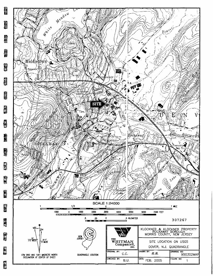
1/2SCALE 1:24000
1 Ull£
1000 1000 2000 3000 4000 5000 6000 7000 FEET
.5 .25 .5 KILOMETER 307267
UTM GRID AND 1981 MAGNETIC NORTHDECUNAITON AT CENTER OF SHEET
QUADRANGLE LOCATION
THE
WHITMANCompanies,
ORIGINAL BY:
C.C.
CHECKED Bf:B.U.
KLOCKNER & KLOCKNER PROPERTYROCKAWAY BOROUGH
MORRIS COUNTY, NEW JERSEY
SITE LOCATION ON USGS
DOVER, N.J. QUADRANGLEDRAWN BY:
IX. K.
DATE:FEB. 2005
DRAWING NO:
950302MAPFIGURE NO:

SOURCE:AERIAL SURVEY DATED JUNE 1994 PREPAREDBY ROBINSON AERIAL SURVEY'S INC. FORCONESTOGA-ROVERS & ASSOCIATES
307268
WHITMANCompanies,
ORIGINAL BY:
LZ.
CHECKED BY:B.U.
KLOCKNER & KLOCKNER PROPERTYROCKAWAY BOROUGH
MORRIS COUNTY, NEW JERSEY
SITE MAP OF
KLOCKNER PROPERTY
DRAWN BY: a. to.DATE:
FEB. 2005
DRAWING NO:950302X9
FIGURE NO:

iSSNDS-10A1-1.5'TCE-0.22
SSNDS-10B4.5-5'rCE-ND
N
SSNDS-9A1.5-2'rCE-0.19
SSNDS-9B4.5-5.0'rCE-ND
SSNDS-4A1.5-2'TCE-2.3
SSNDS-4B4.5-5.0'rCE-0.18 I,
T-f-~
SSF5-1A0.5- VTCE-23
SSF5-105-5.5'TCE-ND
©SSAW-161.5-2'TCE-7.6
SSAW-D1.5-2'TCE-9.4
©SSNDS-11-1.5'TCE-90
SSNDS-1C4.5-5'rCE-ND
SSNDS-21.5-2'rCE-6.2
SSNDS-2C5-5.5'rCE-ND
\ NORTH DRUM STORAGE AREA
\
\
FENCE\
LEGEND
• - SOIL SAMPLE LOCATION
SSNDS-7A1.5-2'TCE-ND
SSNDS-7B4.5-5'TCE-ND
©
SSAW-75-5.5'rCE-0.283
SSAW-712-12.5'TCE-0.648
SSAW-101-1.5'TCE-21.2
BUILDING12
WITH SAMPLE DEPTH IN FEETAND RESULTS IN MG/KG
• - SOIL SAMPLE LOCATION OCTOBER 1998
© - SOIL SAMPLE LOCATION FEBRUARY/AUGUST 2000
TCE - TRICHLOROETHYLENE
ND - NOT DETECTED
NOTE: RESULTS IN BOLD EXCEED NJDEP IMPACT TO GROUND WATER
SOIL CLEANUP CRITERIA OF 1 mg/kg FOR TCE.
TCE 1 mg/kg- ISOCONCENTRATION LINE (ESTIMATED)
©,SSAW-241-1.5'FCE-0.31
©
269
SSAW-231-1.5'TCE-0.35
SSAW-DUP1-1.5'TCE-0.21
TCE 23 mg/kg B'
TCE-90
TCE-3
- ISOCONCENTRATION LINE (ESTIMATED)
- TCE CONCENTRATION AT OR ABOVE 23 mg/kg
- TCE CONCENTRATION ABOVE 1 mg/kg
A' - CROSS SECTION LINE (SEE FIGURES 5 & 6) SCALE
20'
THE
WHITMANCompanies,
ORIG. BY:
950302E7
KLOCKNER & KLOCKNER PROPERTYROCKAWAY BOROUGH
MORRIS COUNTY, NJ
0-6 FOOT DEPTH SOIL SAMPLERESULTS AND ISOPETH FOR TCE
BUILDING 12
DWG. BY:
DATE: FEB. 2005
CHK. BY:
FIGURE:

B
§
IIIIII
IIIIBBB
NORTH DRUM STORAGE AREA
©
PCE
ND
FENCE
LEGEND
- SOIL SAMPLE LOCATIONWITH SAMPLE DEPTH IN FEETAND RESULTS IN MG/KG
- SOIL SAMPLE LOCATION OCTOBER 1998
- SOIL SAMPLE LOCATION FEBRUARY/AUGUST 2000
- TETRACHLORETHYLENE
- NOT DETECTED
NOTE:
RESULTS IN BOLD EXCEED NJDEP IMPACT TO GROUND WATERSOIL CLEANUP CRITERIA OF 1 mg/kg FOR PCE
PCC-3
PCE-5
ISOCONCENTRATION LINE (ESTIMATED)
ISOCONCENTRATION UNE (ESTIMATED)
ISOCONCENTRATION LINE (ESTIMATED)
PCE CONCENTRATION ABOVE 1 mg/kg
PCE CONCENTRATION AT OR ABOVE 4 mg/kg
PCE CONCENTRATION AT OR ABOVE 6 mg/kg
CROSS SECTION LINE (SEE FIGURE 12)
SCALE
20'
THE
WHITMANCompanies,
INC.
ORIG. BY: [_.Z.
G.#: 95Q302F2
KLOCKNER & KLOCKNER PROPERTYROCKAWAY BOROUGHMORRIS COUNTY, NJ
0-6 FOOT DEPTH SOIL SAMPLERESULTS AND ISOPETH FOR PCE
BUILDING 12
DWG. BY: &
DATE: FEB. 2005
CHK. BY:
FIGURE:

I
0 FEET
5 FEET
10 FEET-
15 FEET-
*:'?.£&:*£$• •-ir' ^ ' rx ; ;i.4f ^^:^5^S^^-y^-^tv^v5' i ^
-t—i— i—i—i—i—i—i—i—i—»—-t—i—i—i—i—i—i—i+ + + • » • • » - + • » • • » - • » • + • + + + + - * - ' . ' =
+ + + + + + _+ —*- lfl ' " ~ !~r~ ~rr~ ~
FEET
5 FEET
10 FEET
15 FEET
I
20 FEET-
LEGEND
- SOIL SAMPLE LOCATIONWITH RESULTS IN MG/KG
TCE-32.3
20 FEET
TCE 1 mg/kg
TCE 23 mg/kg
- ISOCONCENTRATION LINE (ESTIMATED)
- ISOCONCENTRATION LINE (ESTIMATED)
- SILTY SAND AND GRAVEL
- SILTY FINE SAND
- SILTY CLAY WITH SAND AND SOME GRAVEL
- SILTY CLAY WITH SAND
- MEDIUM SAND
NOTE:SEE EIGURE 3 FOR CROSS SECTION LOCATION
307271
TCE - TRICHLOROETHYLENE
ND - NOT DETECTED HORIZONTAL SCALE
0 5'
VERTICAL SCALE
** - THE TCE RESULT FOR SAMPLE SSAW-1 WAS NOT USED IN THE PREPARATION OF THE ISOCONCENTRATION LINES. IT IS JUST ABOVE THE
NEW JERSEY IMPACT TO GROUND WATER SOIL CLEANUP CRITERIA OF 1 MG/KG AND MAY BE THE RESULT OF CONTAMINANT DIFFUSION FROM
THE GROUND WATER TO THE SOIL AT THE CAPILLARY ZONE.
THEWHITMAN
Companies,me.
ORIGINAL BY:C.C.
CHECKED BY:M.M.
KLOCKNER & KLOCKNER PROPERTYROCKAWAY BOROUGH
MORRIS COUNTY, NEW JERSEY
CROSS SECTION A-A'
BUILDING 12 TCE RESULTS
(K.K.
FEB. 2005
DRAWING NO.
950302E8

B'0 FEET O FEET
5 FEET
~m • TCE-ND- -=&K- ••£ —1
20 FEET
- SOIL SAMPLE LOCATIONWITH RESULTS IN MG/KG
|TCE-23.2
LEGEND
TCE 1 mg/kg
TCE 23 mg/kg
TCE-90
- ISOCONCENTRATION LINE (ESTIMATED)
- ISOCONCENTRATION LINE (ESTIMATED)
- TCE CONCENTRATION AT OR ABOVE 23 mg/kg
- TCE CONCENTRATION ABOVE 1 mg/kg
TCE - TRICHLOROETHYLENE
ND - NOT DETECTED
0 20'
HORIZONTAL SCALE
0 5'
VERTICAL SCALE
NOTES:
1. SEE FIGURE 3 FOR CROSS SECTION LOCATION
** - THE TCE RESULT FOR THE SAMPLE SSSP-1 WAS NOT USED IN THE PREPARATION OF THE ISOCONCENTRATION LINES BECAUSE THE SAMPLE
WAS COLLECTED FROM BELOW THE INVERT OF A SUMP AND IS AN ANOMALY WITH RESPECT TO THE PREPARATION OF THE ISOCONCENTRATION
LINES FOR THE AREA WIDE CONTAMINATION.
THE
WHITMANCompanies,
me.ORIGINAL BY:
C.C.
CHECKED BT:B.U.
KLOCKNER & KLOCKNER PROPERTYROCKAWAY BOROUGH
MORRIS COUNTY, NEW' JERSEY
CROSS SECTION B-B'
BUILDING 12-TCE RESULTS
cieCATE
FEB. 2005
DRNV1NG NO:
950302C4
J

1
5
IIIIIIiIIIIBII
4
IDZUJ
3
O
te 2
SANITARYSEWER
CONNECTION
2 3ELM STREET
4 5
UJUJDC
CO
OQCDOO
LEGEND
SSFA-44.28
0.5-1'
- SOIL SAMPLE LOCATIONRESULTS IN MG/KGSAMPLE DEPTH
PROPERTYBOUNDARY
TCE - TRICHLOROETHYLENE
PCE - TETRACHLOROETHYLENE
NO - NOT DETECTED
PCE 1 mg/kg _ (SOCONCENTRATION LINE (ESTIMATED)
PCE-3 - PCE CONCENTRATION ABOVE 1 mg/kg
*f f - CROSS SECTION LINE (SEE FIGURE 8)
NOTE: RESULTS IN GREEN EXCEED NJDEP CRITERIA.
SCALE307273
40'
THE
WHITMANCompanies,
ORIG. BY: B.U.
DWG.#: 950302F3
KLOCKNER & KLOCKNER PROPERTYROCKAWAY BOROUGH
MORRIS COUNTY, NJ
0-6 FOOT SOIL SAMPLE RESULTS &
ISOPLETH FOR PCE - BUILDING 13
DWG. BY:
DATE: FEB. 2005
CHK. BY: B.U.
FIGURE: 7

0 FEET
5 FEET - =
10 FEET- -
15 FEET-
FEET
5 FEET
10 FEET
28 FEET
LEGEND
- SOIL SAMPLE LOCATIONWITH RESULTS IN MG/KG
| PCE-0.161
PCE - TETRACHLOROETHYLENE
ND - NOT DETECTED
PCE 1 mg/kg
PCE_4 mg/kg
PCE-4.28
PCE-1.51
- SILTY SAND AND GRAVEL
- SILTY FINE SAND
- SILTY CLAY WITH SAND AND SOME GRAVEL
- GRAVEL
- 1SOCONCENTRATION LINE (ESTIMATED)
- ISOCONCENTRATION LINE (ESTIMATED)
- PCE CONCENTRATION AT OR ABOVE 4 mg/kg
- PCE CONCENTRATION ABOVE 1 mg/kg
307274
NOTE:SEE FIGURE 7 FOR CROSS SECTION LOCATION
HORIZONTAL SCALE
0 5'
VERTICAL SCALE
WHITMANCompanies,
me.ORIGINAL BT:
C.C.
CHECKED Bf:M.M.
KLOCKNER & KLOCKNER PROPERTYROCKAWAY BOROUGH
MORRIS COUNTY, NEW JERSEY
CROSS SECTION C-C'
BUILDING 13
AUGUST 2004
DRAWING NO:
950302E5FIGURE NO:

ei SSNDS-10A
1-1.5'
TCE-0.22
PCE-ND
SSNDS-10B
4.5-5'
TCE-ND
PCE-ND
SSNDS-10C
7-7.5'
TCE-ND
PCE-ND
N
I
I
I
I
I
I
I
I
I
I
SSNDS-9A
1.5-2'
TCE-0.19
PCE-ND
SSNDS-9B
4.5-5.0'
TCE-ND
PCE-ND
PCE-N1
SSNDS-4A
1.5-2'
rCE-2.3
PCE-ND
SSNDS-4B
4.5-5.0'
TCE-0.18
PCE-ND
\ ,
\ \
1
PROPFRTYBOUNDAFT
S8NDS-3A
1-1.5'TTF O 47
PCE-ND
SSNDS-3B
4.5-5.0'
PCE-ND
f
\(.
<i
/
SSFS-3A SSFS-3B SSFS-3C
0-0.5' 2-2.5' 2-2.5'
PB-841 TCE-0.71 PB-373
SSFS-7A
0-0.5'PB-145
!>
)
_- SSFS-6A
. — - ' " 0-0.5'' PR R R
^
©
I
TCE-NA
PCE-NA
PB-471
\
^
TCE-23
PCE-ND
PB-NA
*-U-OC£-lJ
/
SSFS-4AO-O.S'
TCE-NA
PCE-NA
PB-77.3
rCE-ND
PCE-NO
PB-NA
SSAW-5 SSAW1.5-2' 11-TCEPCE
SSAW -17
4-4.5'
TCE-ND
PCE-
'—511.5'
-10.6 TCE-ND-5. £5 PCE-ND
ML)
(I)
SSAW— 1 8
1 5 2 '
TCE ND
PCE-ND
W
.
\ \ SSNSS-1
1-1.&.
TCE-90' >
PCE-ND
SSNDS-1C
4.5-5'
[CE-ND
PCE^HD'
SSNDS-1D
12-12-5'-
TCE-I^D
PCE-ND
PB-128
QUONS^T HUTSSAW-62-2.5'TCE-65.9PCE-23.7
SSAW-69-9.5'TCE-NDPCE-ND
h\SSNDS-2
1.5-2'
TCE-6.2
PCE-0.13
SSNDS-fiC
5-5.5' /
TCE-N6
PCE/ND
NORTH DRUM STORAGE AREA
^\NOTE:
RESULTS IN BOLDV EXCEED NJDEP IMPACT TO GROUND WATER
SOIL CLEANUP CRITERIA OF 1 mg/kg FOR TCE AND PCE
AND NJDEP RESIDENTIAL DIRECT CONTACT SOIL CLEANUP CRITERIAOF 400 MG/KG FOR LEAD.
• SSC8-1
FENCE
%
\ SSNDS-7A
1.5-2'
TCE-ND
PCE-ND
SSNDS-7B
4.5-5'
TCE-ND
PCE-ND
©
SSAW-7
5-5.5'
TCE-0.283
PCE-ND
SSAW-7
12-12.5'
TCE-0.648
PCE-ND
©SSAW- 16
1.5-2'
TCE-7.6
PCE-ND
SSAW-D
1.5-2'
TCE-9.4
PCE-ND
\
BUILDING
12
SSA^-9
l-vis:
rcE-2X3~PCE-ND
SSAW-9
5-5.5'
TCE=0.44-
PCE-ND
SSAW-9 /
/11.5-J2'
TCE-HD
PCE-ND
,. SHELFSTORAGE
SHIPPINGROOM
III
CIS
©TCE
PCE
PB
;-1,2-DCE
ND
- SOIL SAMPLE LOCATION
WITH SAMPLE DEPTH IN FEET
AND RESULTS IN MG/KG
- SOIL SAMPLE LOCATION OCTOBER 1998
- SOIL SAMPLE LOCATION FEBRUARY/AUGUST 2000
- TRICHLOROETHYLENE
- TETRACHLORETHYLENE
- LEAD
- CIS-1,2-DICHLOROETHENE
- NOT DETECTED
TCE 1 mg/kg
TCE 23 mg/kg
TCE-90
TCE-3
PB-450
- ISOCONCENTRATION LINE (ESTIMATED)
- ISOCONCENTRATION LINE (ESTIMATED)
- TCE CONCENTRATION AT OR ABOVE 23 mg/kg NOTE:
- TCE CONCENTRATION ABOVE 1 mg/kg
- PB CONCENTRATION ABOVE 400 mg/kg
- PCE CONCENTRATION ABOVE 1 mg/kg
®rSSAW-24
1-1.5'
TCE-0.31
PCE-ND
©
SSAW-4
4-4.5'
TCE-23.2
PCE-ND
1SSAW-2
1.5-2'
TCE- 23.1
PCE-ND
SSAW-4
9.5-10'
TCE-ND
PCE-ND
SSAW-2
7.8-8'
TCE-0.144
PCE-ND
LOADINGBAY
307275
SSAW-231-1.5'TCE-0.35PCE-0.28
SSAW-DUP1-1.5'TCE-0.21PCE-0.27
ONLY RESULTS FOR TCE, PCE. AND PB ARE PLOTTED.
CIS-1.2-DCE INCLUDED WHERE CONCENTRATION EXCEEDS 1 mg/kg
SCALE
0 To*
THE
WHITMANCompanies,
ORIG. BY:
DWG.#: 950302F4
KLOCKNER & KLOCKNER PROPERTYROCKAWAY BOROUGHMORRIS COUNTY, NJ
SOIL SAMPLE RESULTS ANDSAMPLE LOCATIONS
BUILDING 12
DWG. BY:
DATE: FEB. 2005
CHK. BY: B.U.
FIGURE: 9

i
0 FEET
5 FEET
10 FEE
SHTJUTTTHSAND ft vvftA^L
PCE-ND
PCE-ND PCE-ND
SOY
I
v>iin
SOYICIAY
SAND
SLTY CXAY
PCE IND
SANDSUYISAND
-0 FEET
-5 FEET
-10 FEET
15 FEET-
IPCE-ND
-10 FEET
20 FEET- -20 FEET
W- SOIL SAMPLE LOCATION
WITH RESULTS IN MG/KG
PCE-5.85
LEGEND
PCE 1 mg/kg
PCE 4 mg/kg
PCE-23.7
PCE-2.1
NOTE: SEE FIGURE 3 FOR CROSS SECTION LOCATION
ISOCONCENTRATION LINE (ESTIMATED) c
ISOCONCENTRATION LINE (ESTIMATED)
PCE CONCENTRATION AT OR ABOVE 4 mg/kg
PCE CONCENTRATION ABOVE 1 mg/kg I
PCE - TETRACHLOROETHYLENEND - NOT DETECTED
307276
HORIZONTAL SCALE
VERTICAL SCALE
WHITMANCompanies,
ORIGINAL ETV:LZ.
CHECKED BY:
LZ.
KLOCKNER & KLOCKNER PROPERTYROCKAWAY BOROUGH
MORRIS COUNTY, NEW JERSEY
CROSS SECTION B-B'
BUILDING 12 - PCE RESULTS
DRAWN BY:
K.K.
FEBRUARY 2005
DRAWING NO:
950302F5FIGURE NO:
10
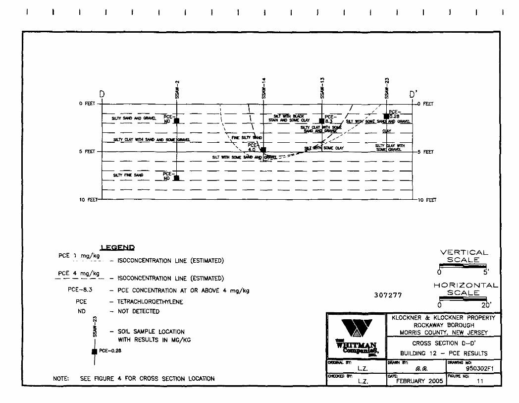
D0 FEET
5 FEET
10 FEET
FEET
5 FED"
10 FEET
LgCSENP
PCE 1 mg/kq?C A - ISOCONCENTRATION LINE (ESTIMATED)
PCE 4 mg/kg— ISOCONCENTRATION LINE (ESTIMATED)
- PCE CONCENTRATION AT OR ABOVE 4 mg/kg
- TETRACHLORQETHYLENE
- NOT DETECTED
PCE-8.3307277
VERTICALSCALE
HORIZONTALSCALE
PCE
ND
M- SOIL SAMPLE LOCATION
WITH RESULTS IN MG/KG
PCE-0.28
NOTE: SEE FIGURE 4 FOR CROSS SECTION LOCATION
"gffisas.ORIGINAL BY:
L.Z.
CHEEKED BT;
L.Z.
KLOCKNER & KLOCKNER PROPERTYROCKAWAY BOROUGH
MORRIS COUNTY, NEW JERSEY
CROSS SECTION D-D'
BUILDING 12 - PCE RESULTS
DRAWN BY:
OATE:FEBRUARY 2005
DRAWING NO;
950302F1FIGURE NO;
11

I2m
307278

307279

HII
RB ATTACHMENT 1
DEPTH TO GROUND WATER INFORMATION
ni
307280
nH
THEWHITMANCOMPANIES, INC.
G:\PROJECTSM995\95-03-02Klockner\R-Tecliinemo-March2005.DOC

TABLE 1
KLOCKNER & KLQCKNER
SHALLOW GROUND WATER ELEVATIONS MEASURED BY KLOCKNER'S CONSULTANTS
MonitoringWdl
M W - I S
MW-2S
MW-3S
MW-4S
MW-5S
MW-6S
MW-7S
P-l
Top of Casing(feet, MSL)
523.40
525.29
524.71
522.63
522.86
522.45
522.87
525.35
Ground SurfaceElevation
(led, MSL)
523.8
523.0
523.2
523.0
523.2
522.6
523.4
522.8
8/7/87
WaterTable
Elevationfleet. MSL)
510.19
510.46
510.51
-
-
-
-
- •
DepthBdowGrade(feet)
13.61
12.54
12.69
-
-
-
-
-
9/23/87
WaterTable
Elevation(feet MSL)
510.51
510.78
510.80
-
-
-
-
-
DepthBelowGrade(feel)
13.29
12.22
12.40
-
-
-
-
-
12/K/sa
WaterTable
Sevatkxi(feet, MSL)
509.38
509.54
509.59
-
509.69
509.74
-
-
OeplhBelowGrade(feel)
14.42
13.46
13.61
-
13.51
12.26
-
-
9/27/89
WaterTable
Qevalion((eel, MSL)
511.03
511.26
511.29
511.95
511.24
5 1 1 . 2 1
511.33
511.29
DepthBeiowGradefleet)
12.77
11.74
11.91
11.05
11.96
11.39
12.07
11.51
10/26/89
WaterTable
Elevation(feet MSL)
511.54
511.58
511.66
511.69
511.72
511.72
511.63
511.55
DepthBdowGrade(feel)
12.26
11.42
11.54
11.31
11.48
10.88
11.77
11.25
11/13/83
WaterTable
Elevation(feet, MSL)
511.48
511.61
511.63
511.69
511.64
511.64
511.57
511.58
DepthBelowGrade(feet)
12.32
11.39
11.57
11.31
11.56
10.96
11.83
11.22
Range(feet)
12.26-14.42
11.39-13.46
1 1.54-13.61
11.05-11.31
11.48-13.51
10.88-12.86
11.77-12.07
1 1 .22-11.51
Fluctuation(feet)
2.16
2.04
2.07
0.26
2.03
1.98
0.3
0.29
Key
MSL - Mean Sea Level
Note: All wells listed are located on the Building 12 property.
307281

TABLE!
KLOCKNER * KLOCKNER
SHALLOW GROUND WATER ELEVATIONS '
Mooitow^We*
MW-1S
MW-2S
MW-3S
MW-4S
MW-5S
MW-6S
MW-7S
FG-I
Topo<Casng
(Ied.MSL)
524.09
5Z5.97
525.39
523.31
523.38
522,99
523.56
524.04
Grounda«t>oe
Efevafion(k*t.MSl)
524.48
523.81
523.94
523.68
523.87
523 0.6
524.05
524.66
1CW83
WaterTat*:
pectMsg
511.59
512.57
512.01
-
-
-
-
-
OepUiBelowGrade(TeeO
12.89
11.24
11,93
-
-
-
-
-
9/11/XW/f.WO
WaterTable
Sevatxxi(TecCMStj
511.79
511.77
510.99
511.81
511.96
511.99
511.86
-
DepthBelowGrade
12.69
12.04
12.95
11. S7
1S.91
11.27
12.19
-
3/Z4/!»a/Z7flO
WaterTable
SevaSon(feet.MSy
-
-
-
-
-
-
-
510.84
DepthBelowGrade
-
-
-
-
-
-
-
13.82
icW»
WaterTabk
Sevation(led. MSI)
510.77
511.42
511.46
511.43
511.40
511.40
511.37
510.62
OepUiBdo*Grade
13.71
12.39
12.48
12J5
12.47
11.86
12.68
14.04
i<Ww
WateTable
Bevatnn
510.74
511.39
511.41
511.69
511.40
5I1J7
511.34
510.58
OeplhBdowGrade
13.74
12.42
12.53
11.99
12.47
11.89
12.71
14.08
HV10/DO
Water TableBevalion
(leAMSlJ
510.71
511.37
5 I K 4 Q
511.85
511.37
511.36
511.32
510.56
OepUiBetawGrade(<ee4
13.77
12.44
12.54
11.83
12 JO
11.90
12.73
14.10
11/16/90
Water TableBevatkxi
(leetMSl)
510.69
511.29
511.30
511.43
511-29
511.29
511.22
510.43
depthBelowGrade
13.79
12.52
12.64
12.25
12.58
11.97
12.83
14.23
12/2H90
Water TableBcvatkm(fea,Msq
511^3
511.47
511.51
511.93
511.51
511.52
511.43
510.73
DepthBelowGrade(fed)
13.25
12.34
12.43
11.75
12.36
11.74
12.62
13.93
1/16,91
Water TableBevatiort
(teat-MSq
511.59
511.82
511.83
512.53
511-86
511.84
511.77
511.09
Oeptt.BelowGrade(led)
12.89
10.99
12.11
11.15
12.01
11.42
12.58
13.57
Range
<<e<*)
12.69-13.79
10.99-12J2
11.93-12.9.5
11.15-12.25
11.91-12.58
1IJ27-11.97
12.19-12.83
13.57-14^3
fluctuation(led)
1.10
1.53
1.02
1.10
0.67
0.70
0.64
0.66
Key
MSL - Mean Sea Level
•Information from August 1991 Feasibility Study, Rockaway Borough Well Field Site, Tables l-l and 1-2 by ICF Technology Incorporated
Note: Monitoring well FG-i is located on the Building 13 property. All other wells listed are located on the Building 12 property.
R\WPDOCS\MISC\9503aZ622
307282

SOURCE: FIRST ENVIRONMENT
2Id
IDJy0h(0
SAI-7
L-OCATTION
STATE:LOCATIOV4
307283
NOT TO SCALE
THE
WHITMANCompanies,
me.
ORIG. BY:
DWG.#:
KLOCKNER &: KLOCKNER PROPERTYROCKAWAY BOROUGHMORRIS COUNTY. NJ
MONITORING WELL LOCATIONS
DWG. BY:
DATE: NOV. 1995
CHK. BY: MM
FIGURE: J.12

S25 i—
LEGEND
APPROXIMATE HORIZONTAL SCALE
INCH-100 FEET
PERCHEO WATER TABLE
INFERRED GROUNDWATER TABLE
UOMTOfUNQ WELL ANDSCREENED INTERVAL
SOURCE: ICM, 1991
— 525
_ 500
KLOCKNEH AND KLOCKNEH
SILT AND CLAY CONFWNQ UNTT
UNCONSOUOATEO MATERIAL CONSISTING OF
VARIABLE AMOUNTS OF BOULDERS. COBBLES
GRAVELS, SAND. SILT AND CLAY
450
CROSS-SECTION LOCATIONNOT TO SCALE
307284
THEWHITMAN
Companies,INC.
ORIG. 6Y: MM
DWG.#:
KLOCKN.ER &. KLOCKNER PROPERTYROCKAWAY BOROUGHMORRIS COUNTY. NJ
GEOLOGIC AND HYDROGEOLOGIC
CROSS SECTION
DWG.
DATE: NOV. 1995
CHK. BY: MM
FIGURE: 2.9

307285

ATTACHMENT 2
EPA'S JANUARY 20, 2005 LETTER
307286
THEWHITMANCOMPANIES, INC.
G:\PROJECTS\I995W5-03-02 Klockner\R-Teclnnemo-March2005.DOC

UNITED STATES ENVIRONMENTAL PROTECTION AGENCYREGION II
290 BROADWAY
NEW YORK, NEW YORK 10007
EXPRESS MAILRETURN RECEIPT REQUESTED
Mr. Michael Metlitz116 Tices LaneUni t B-lEast Brunswick, New Jersey 08816
Re: Technical Memorandum for the Development and Screening of Alternatives forSite Remediation for the Rockaway Borough Wellfield Superfund Site,Morris County, New Jersey
Dear Mr. Metlitz:
The U.S. Environmental Protection Agency (EPA) and New Jersey Department ofEnvironmental Protection have reviewed the Whitman Companies' September 16, 2004Technical Memorandum for the Development and Screening of Alternatives for SiteRemediation for the Klockner and Klockner portion of the Rockaway BoroughWellf ield site. Please address the following comments:
General Comments:
Please reference the EPA document, "Guidance for Conducting RemedialInvestigations and Feasibility Studies under CERCLA, October 1988", which detailsthe appropriate format to arrive at a detailed analysis of appropriate alternatives.Overall the memorandum does not follow the format for the above-mentioned EPAguidance. For instance, Section 6 (Description of Remedial Technologies) andSection 7 (Initial Screening of Process Options) appear to be part of Section 5(Identif ication and Screening of Remedial Alternatives).
There does not appear to be any supporting figure displaying the Cross Sections A-A'Building 12, B-B' Building 12 , and C-C' Building 12. These cross-sections should bedisplayed on a plan view of the respective building areas for reference by the reviewer.
307287

There needs to be a clear division between the removal of metals and the removal ofVolatile Organic Compounds. The report should have specific sections for theremedial alternatives for the removal of lead as well as removal of TCE andPCE.
Specific Comments:
1. T a b l e o f C o n ten ts - The numbering of Section 6.1.2 (Performance Data) andSection 6.1.3 (Cost) should be Sections 6.1.4 and 6.1.5 respectively.
2. Section 2.2 - last paragraph, Page 4 - Need to better define what depth isconsidered to be saturated. A defined depth as per the 1995 AdministrativeOrder on Consent should be represented in this memorandum.
3. Section 4.1.2 - first paragraph, Page 5 - This paragraph describes theconclusions from the human health risk assessment and should include thesummary from the risk assessment instead of paraphrasing the summary.
4. Section 4.1.2 - Cleanup Criteria Table, Page 6 - The table in Section 4.1.2includes a proposed cleanup concentration for lead and the basis for thisproposal should be either cited or explained in this section..
5. Section 4.3.1 -Lead Contamination, Page 6- The New Jersey ResidentialDirect Contact Soil Cleanup Criteria should be cited.
6. Section 4.3.2 - second paragraph, Page 7 - This paragraph contains vaguereferences that are difficult to follow. For example, it mentions that thequanti tat ion l imit for some of the samples were just above the NJIGWSCC of 1mg/kg, then it indicates that the TCE concentrations in the noted sample were allabove 19 mg/kg. It is unclear which samples are the "noted samples" and therelationship between the detection limit and quantitation limit need to be betterexplained.
7. Section 4.3.2 - second paragraph, Page 7 - In the last paragraph it says that "thevertical and horizontal extent of the PCE affected areas has been delineated",however, there are no cross-section figures to support this statement.
8. Section 5.2 - Identification of Remedial Technologies and Process OptionsPotentially Available, Page 8 - This section includes the statement that, " Thefollowing is a list of possible remediation alternatives for the Klockner Property.These process options and how they fared in the initial screening are summarizedin Section 8." Remedial Alternatives are different than remedial technologiesand process options, and the statement should be corrected accordingly.
307288

9. Section 5,2 - Identification of Remedial Technologies and Process OptionsPotentially Available, Item 3, In-situ Treatment, Page 9 - The third bullet ofthis item should be written "Thermal treatment combined with vapor extraction"for consistency with Table 1.
10. Section 5.2.5 - Cost Evaluat ion, Page 10 - It should be noted that, inaccordance with CERCLA protocols, the cost evaluation at this stage is intendedto provide a relative comparison of process options (e.g., asphalt, clay, soil)within a technology type (e.g., capping), not among all process options.
11. Tab l e l ,Page l l
- The first cell "No Further Action Further Action" should read "NoAction"since no action has been taken at the site. The No Action Alternative isrequired to be used as a baseline to compare the other al ternat ives and cannot belisted as not acceptable.
- The third cell "Institutional Controls" shows that process options are notapplicable, however, there are insti tutional controls that are applicable such as,deed restr ict ion. Please research this option more thoroughly.
- This table is intended to address TCE and PCE issues and should not includereferences to lead, which is the subject of Table 2.
- Process Options are referenced in the text that are not included in Table 1 (e.g.,radio frequency/electromagnetic heating and bioventing).
- The format in Tables 1, 2, and 3 is confusing because CERCLA terms such asGeneral Response Actions, Remedial Technology Categories, Process Options,and Remedial Alternatives are not utilized, presented and applied in a consistentmanner nor are they in accordance with CERCLA protocols.
12. Section 6.0 Description of the Remedial Technologies, Page 14 - The materialpresented in this section should be clarified since not all remedial technologiesare not discussed and the section should be renamed as the "Description ofSeriously Considered Remedial Technologies" or similar.
13. Section 6.1 - Soil Vapor Extraction, Page 15 - The last sentence on page 15states that, "The duration of operation and maintenance for in-situ SVE istypically medium-to-long-term." However, in Section 6.1.4 Performance Data(incorrectly numbered 6.1.2 in the document) it states that SVE projects aretypical ly completed in 1 to 3 years. These appear to be inconsistent, as 3 yearswould not typically be considered a long-term remediation.
307289

H
14. Section 6.5.2 - Applicability, first bullet, Page 25 - Please revise to indicatethat there is a potential for complete destruction of PCE and TCE without theformation of harmful byproducts. In addition, please take in to account the nextcomment in regard to this bullet.
15. Section 6.5.3 - Limitations, first bullet, Page 26 - Please revise to indicate thatthere is a potential for incomplete oxidation or formation of intermediatecontaminants that are more toxic that the original contaminants and oxidiz ingagents used. As mentioned in the above comment, the first bullet for theadvantage and disadvantage of using in situ chemical oxidation provideconflicting information. Although both statements are true, more detail shouldbe provided to show that detoxification occurs more frequently than the creationof more toxic degradation products, if this is true, to support the advantageclassification.
16. Section 6.5.3 - Limitations, third bullet, Page 26 - This item refers to"...ex-situ remedy..." However, the entire section is developed for in-situchemical oxidation.
17. Section 6.5.6 - Cost, Page 27 - The text indicates that the cost figures are notavailable for in-situ oxidation; however, Table 3, which seems to list this sameresponse action twice, indicates this as a high cost process option.
18. Table 3 - Screening and Elimination of Process Options, Pages 27 and 28- Tables 1 and 2 were intended to evaluate Process Options, and Table 3 isintended to screen and eliminate Process Options. A number of process optionsthat were evaluated in Tables 1 and 2 are not included in Table 3 and should beadded (e.g., institutional controls, bioventing, ex-situ soil washing, etc.)
- Either the first column in the table should be retitled Process Options or thetitle of the table should be changed to match the name of the first column.
- Either the second reference to In-situ Chemical Treatment should be removedor designation as ozone or hydrogen peroxide needs to be added.
- Table 3 shows the No Action alternative as implementable, but in Tables 1 and2 it is listed as not acceptable to local/federal authorities. This inconsistencyneeds to be addressed.
- Please indicate why SVE with Thermal Desorption was not considered as apreliminary remedial alternative as the qualifiers in each column are identical toSVE with steam injection, which was considered as a preliminary remedialalternative.
307290

III
n
III
- Please add a Table 4 to list the preliminary remedial alternatives for lead.
19. Section 8.0 - Surviving Process Options, Page 28 - The list of survivingprocess options seems to be.missing.
20. Section 8.1.1 - Alternative 1: No Action, Page 30 - No Action was not asurviving Process Option as presented in Table 3. However, a No Actional ternat ive is required to be developed under CERCLA protocols. Somestatement should be added to clarify to the reader as to why this is s t i l l anal ternat ive even though it was el iminated in Table 3.
21. SectionS.1.1 - A l t e r n a t i v e l : N o A c t i o n , P a g e 3 0 - T h e paragraph t i t l ed"Time" includes discussion regarding degradation of TCE and PCE over t ime,however, there is no mention of lead in this discussion. Please add a descriptionor another section that details the time for lead at tenuat ion.
22. Section 8.1.2 - Alternative 2: Monitored Natura l At tenua t ion , Ins t i tu t iona lControls and Engineering Controls, Page 31 - In order to include Ins t i tu t iona lControls as a surviving Process Option in Section 8, they should be screened asa Process Option as presented in Table 3. Please either remove the reference toInst i tut ional Controls in this section or add them to the screening process.
23. Section 8.1.2.1 - Alternative 2: Monitored Natura l At tenua t ion , Page 31 - Itis stated that the Klockner property is an ideal candidate for monitoredattenuation based on the low potential for chemical migration. As the primaryobjective is to prevent impact to groundwater from soil contamination,monitored natural attenuation does not appear to be a desired alternative. Inaddition, lead does not naturally attenuate unless d i lu t ion due to migrat ion isconsidered, which again does not support natural at tenuation as a desiredalternat ive.
24. Section 8.1.2.3 - Alternative 2: Engineering Controls, first paragraph, Page32 - This paragraph states that the advantages to using an engineering control(i.e., cap) as a desired alternative. It states that a cap would restrict inf i l t ra t ionof water through the soil and would, therefore, restrict the movement ofcontaminants through the soil and into the groundwater. However, there is nomention made regarding the abil i ty for groundwater elevations to fluctuatewhich would allow contaminant migrat ion to occur through direct contact withgroundwater, thus making this alternative less desirable than other al ternatives.
307291

IBII0ffi
I
lit
25. Section 8.1.2.3 - Alternative 2: Engineering Controls, third paragraph, Page31 - Please add "for TCE and PCE" between "standard" and "would" in the thirdsentence. In addition, please revise the last sentence to reflect that the cleanuphorizon for this alternative would be similar or longer than the monitorednatural attenuation and somewhat longer than the active remediationalternatives.
26. Section 8.1.3-Alternat ive 3 . -Excava t ion-On or Off Site Treatment , Pages32 and 33-
- The four waste management Process Options that are presented in tandem withexcavation were not screened as Process Options as presented in Table 3.
- This section states that excavation is not viable because it would resul t indisrupt ion of business. If that is correct, then excavation should not be asurv iv ing Process Option as presented in Table 3.
- Excavat ion could also be staged to reduce the impact to business operations.
- There should be an addit ional section that addresses partial excavation for theexter ior lead contaminated area, so that it is clear that par t ia l excavat ion is aviable alternative.
27. Sect ion 8.1.4.1-In Situ Chemical Treatment , Page 33- In-s i tu chemica ltreatment was not a surviving Process Option as presented in Table 3.
28. Section 8.1.5-Soil Vapor E x t r a c t i o n , P a g e 3 4 - I f s o i l vapor ext rac t ionmethods are utilized for sub-slab remediation at the Klockner site, this sectionshould address methods to ensure that "clayey silty soils" (low permeabili tysoils) will be treated effectively and that pore air flow will not s imply bypassaround these soils and through adjacent higher permeabili ty soils dur ing in-s i tutreatment.
29. Section 9.0 - Conclusion, Pages 34 and 35 - The first paragraph includesincorrect statements regarding the survival of initial screening. This paragraph,combined with the previous inconsistent use of terminology and the previousinconsistent evaluation and screening results, does not provide a clearly definedpath to the selection of "the most viable options for the Klockner Property." Forinstance, there does not seem to be enough supporting documentation to make aninformed decision on a viable remedial option for lead. However, the options asstated in the conclusion section may be appropriate.
307292
HI
In accordance with Section VIII, paragraph 35 of the Administrative Order on Consent,an amended Technical Memorandum is due 30 days after receipt of this letter.
Should you have any questions or comments on any of the above, please contact BrianQuinn, of my staff, at 212-637-4381.
Sincerely yours,
Carole Petersen, ChiefNew Jersey Remediation Branch
cc: David L. Isabel, Riker, Danzig, Scherer, Hyland & Perretti, w/encl.Donna Gaffigan, NJDEP, w/encl.
307293