the uk civil hydrography programme recent developments · • fm midwater tools available now. •...
TRANSCRIPT

The UK Civil Hydrography Programme Recent Developments David Parker UKHO Civil Hydrography Manager

Introduction (1)David ParkerUKHO Civil Hydrography Manager
• Managing the UKHO’s involvement in the UK Maritime and Coastguard Agency (MCA) run Civil Hydrography Programme (CHP)
• Planning survey areas and technical requirements with the MCA
• Provide technical oversight of the Survey Contractors in the field / office

Introduction (2)David ParkerUKHO Civil Hydrography Manager
• BSc (Hons) in Hydrography and Ocean Science from University of Plymouth.
• Chairman of the Hydrographic Society (UK).
• Chartered Marine Scientist.
• He has worked predominantly in the near shore and port hydrography sector for 16 years

Outline of Presentation• Overview of the CHP
• Recent Developments;
• Multibeam Water Column Data
• Bathymetric Surfaces
• GNSS Height + VORF
• Existing UK Data Coverage and Future Plans

Overview of the Civil Hydrography Programme
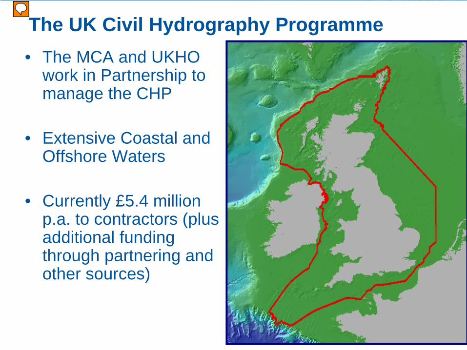
The UK Civil Hydrography Programme• The MCA and UKHO
work in Partnership to manage the CHP
• Extensive Coastal and Offshore Waters
• Currently £5.4 million p.a. to contractors (plus additional funding through partnering and other sources)
Long Term Contracts
• 2 x Long term contracts let: 2 + 2 years:• Shallow water – EMU Ltd• Shallow and Medium water – NetSurvey / MMT• Routine Resurvey Areas – NetSurvey / MMT
• Emergency Towing Vessel• No longer operating
• Other Partnering Projects• Channel Coastal Observatory• INIS Hydro

CHP Contract VesselsMBES used: EM2040, EM3002, EM710, SeaBat 7125
Example Vessels of the CHP
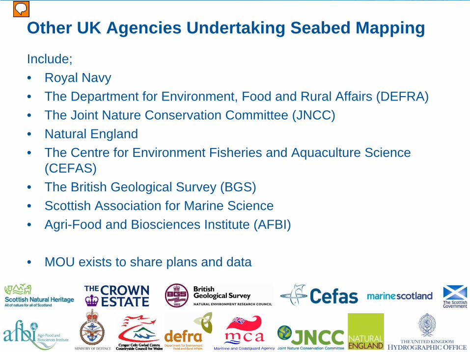
Other UK Agencies Undertaking Seabed Mapping
Include;• Royal Navy• The Department for Environment, Food and Rural Affairs (DEFRA) • The Joint Nature Conservation Committee (JNCC)• Natural England• The Centre for Environment Fisheries and Aquaculture Science
(CEFAS)• The British Geological Survey (BGS)• Scottish Association for Marine Science• Agri-Food and Biosciences Institute (AFBI)
• MOU exists to share plans and data

Wreck Investigation Trials – MBES Water Column Data

Requirement for Wreck Surveys• Wrecks present a unique challenge within a
hydrographic survey.
• Previous UKHO trials have already highlighted issues with multibeam depths on wrecks.
• Normally a wreck investigation will be undertaken at each wreck site within a larger survey.
• Wrecks around the UK are very numerous – one recent survey had over 400.

Gardline MBES Water Column Trials

Comparison of MBES Water Column Data
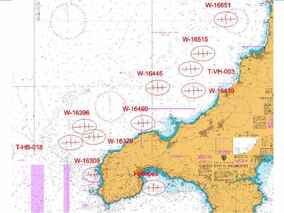
• In 2010, a field trial was undertaken to compare the least depth over wrecks obtained from;
– Wire Sweep– Multibeam conventional bottom detect– Side Scan Sonar– MBES Water Column Data

MBES Water Column Data TrialsVessels;• MV Fugro Mercator• MV Meridia• MV Jetstream
Equipment;• Kongsberg EM 3002D MBES• Kongsberg EM 710 MBES• Reson SeaBat 7125 MBES• Klein 3000 SSS• Pressure Sensor• HiPAP USBL Sub-Sea Positioning• Constant Tension Winch

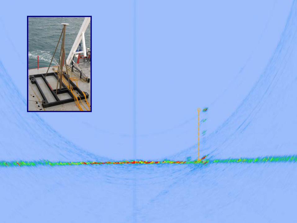
MBES Water Column Data Trials
Post Processing Software:
CARIS HIPS(Bathymetry and SSS)
Fledermaus FM Midwater(MBES Water Column)
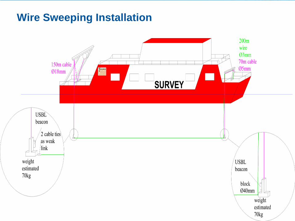
Wire Sweeping Installation
t
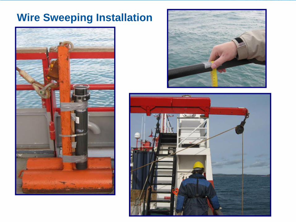
Wire Sweeping Installation


Height of feature above seabed was measured


ResultsNo. Wreck-Name General depth
[m]MBES
least depth [m]
WCDleast depth
[m]
SSS least depth
[m]
Wire sweep cleared depth
[m]
Difference from Next Shoalest
[m]1 Hellopes Boiler 34.00 28.6 28.6 28.6 - 0.02 T-FG-009 37.30 36.0 35.9 36.0 - 0.13 T-FG-014 34.20 30.3 30.1 30.3 - 0.24 T-FG-016 37.00 29.6 29.6 29.6 - 0.05 T-HB-018 43.00 38.2 38.0 38.2 - 0.26 T-VH-003 41.00 35.6 35.6 35.3 - 0.37 W-16309 40.00 31.6 31.8 31.8 - 0.210 W-16400 28.90 20.3 20.4 20.8 - 0.111 W-16445 40.00 34.3 32.6 34.3 - 1.712 W-16515 39.00 32.3 32.2 32.3 - 0.214 W-17789 33.00 27.4 24.8 27.3 - 2.616 W-16439 35.00 30.2 30.2 30.2 - 0.017 Hellopes N 33.60 27.1 27.8 26.6 27.3 0.5
18 Hellopes S 34.00 30.0 30.0 30.0 29.5 0.519 W-73522 42.40 35.4 35.7 35.9 34.9 0.520 W-73523 39.00 35.9 35.8 36.0 35.4 0.121 EM710-Frame 18.80 18.8* 15.2 - 15.6 0.3

ResultsMBES
least depth [m]
WCDleast depth
[m]
SSS least depth
[m]
Wire sweep cleared depth
[m]
Difference from Next Shoalest
[m]28.6 28.6 28.6 - 0.036.0 35.9 36.0 - 0.130.3 30.1 30.3 - 0.229.6 29.6 29.6 - 0.038.2 38.0 38.2 - 0.235.6 35.6 35.3 - 0.331.6 31.8 31.8 - 0.220.3 20.4 20.8 - 0.134.3 32.6 34.3 - 1.732.3 32.2 32.3 - 0.227.4 24.8 27.3 - 2.630.2 30.2 30.2 - 0.027.1 27.8 26.6 27.3 0.5
30.0 30.0 30.0 29.5 0.535.4 35.7 35.9 34.9 0.535.9 35.8 36.0 35.4 0.118.8* 15.2 - 15.6 0.3

Conclusions 1• The “real time” bottom detect from a MBES will not
necessarily give the shallowest legitimate depth within the beam.
• SSS can give valuable extra information about dangerous protruding parts of wrecks, but this requires a towfish in the water, which can cause problems with static fishing gear.
• Wire sweeping is difficult and time consuming, and can be unreliable.

Conclusions 2• Wire sweeping is not only limited by fishing gear and
other maritime traffic; it can also be dangerous to the ship conducting it.
• MBES WCD appears to provide reliable information about protruding parts of wrecks which the MBES alone may miss.
• WCD resolution is normally comparable to a good SSS, but has the advantage of being quicker and easier to gather.

Current WCD Software• The tools for analysing and utilising WCD are
fairly new, and will improve with time.
• FM Midwater tools available now.
• Echoview Software Currently available, but oriented towards fisheries applications.
• CARIS are introducing their WCD tool with CARIS HIPS v7.1 Service Pack 1 in Jan 2012 – UKHO have been working with CARIS to develop this tool.

Echoview Using MBES WCD for Biomass Estimate
Current CHP Survey Specification4.2.8
• Swathe Bathymetry Water Column DataSwathe bathymetry water column shall be logged for further analysis during all wreck investigation lines.
• This data shall be analysed in an appropriate software package to compare the data digitised in real time by the swathe bathymetry with other features present in the water column.
Current CHP Survey Specification4.2.8 Continued
• The surveyor shall have the ability to re-pick fully georeferenced depths from the water column data for inclusion in the final sounding data if a shoaler depth over a given feature has been found within the water column data.
• The Contractor will supply images or animations with the RoS showing the water column replay for each wreck to support the designation of least depth.

Bathymetric Surface Deliverable Trial

The Problem with Soundings….
• Modern Multibeam Echosounder (MBES) data is very dense (up to 800 soundings per ping).
• This is great for detail, but it creates data processing and handling problems.
• Also, there will always be noise within the system, creating outliers.
• These outliers need to be isolated and rejected if the data is to be utilised as a sounding set.

Bathymetric Surface Deliverable Trial• In FY 2010/11, UKHO and NetSurvey /
MMT have been testing statistical bathymetric surfaces as the bathymetric deliverable.
• It is hoped that this will allow more rapid progress from “ping to chart”, as the data processing and validation stages should be much quicker.
• Soundings do not need to be “cleaned”.
• It is also hoped that the overall accuracy of the bathymetric product will be improved without compromising safety.


Noise automatically disregarded by algorithm


Manually Designated by Hydrographer

Bathymetric Surface Deliverable Trial
• UKHO and NetSurvey have both been using the surfaces created by CUBE algorithm since 2005, but as a data cleaning aid rather than deliverable.
• Most of the work in creating the specification is stating when a manually designated sounding needs to be used.
• Also detailing the parameters to be used in the algorithm, e.g;
– Cature Radius – Bin Size

Bathymetric Surface Deliverable Trial
• The first year’s surveys have just completed validation.
• Initially results are that processing took 50% of previous timescale.
• Validation should be 60-80% of previous timescale once bugs fixed.
• The deliverable is immediately ready for ingest into bathymetric database.
• Nest phase is to test in rocky area.

GNSS Height and VORF

What is VORF?
• VORF = Vertical Offshore Reference Frame
• A set of mathematical models of the major surfaces used in the current and future charting of UK home waters
• A suite of software utilities allowing the transformation of mapping and positioning data between the VORF surfaces

LAT
Charted depth
depthmeasurement
(and timeof observation)
survey vesselTide gauge
observed tide (and time)
Tidal correctionderived fromUse co-tidal
chart
Measuring Tide to Reduce Soundings
… or use seabed gauge
Sea Surface

Charted depth
depthmeasurement
Tidal correction
Bathymetric data processing with VORF and GPS
GRS80 Ellipsoid
VORFCD
survey vessel (+GPS)
h
Tidal correction = h
– VORF CD
Charted depth = Depth measurement – tidal correction
- ETRS’89 accessible everywhere via GPS
Sea Surface

• VORF covers the entire UK and Irish continental shelves (although individual datums may be limited by their areas of applicability).

GNSS Height and VORF
• All CHP Surveys now utilise post processed GNSS Height and VORF.
• Testing undertaken at more than 50 locations around the UK and Ireland to confirm VORF uncertainty and methodology.
• Data normally post processed using OS active stations - a GNSS aided inertial solution is re- computed using POSPAC (Applanix).
• PPP can be used as an alternative if active network problematic.

Current Coverage and Future Survey Plans

UK Data Coverage and Reliability• Most of the UK now
single beam echosounder + SSS (light green)
• However, the modern standard is now full seafloor coverage (dark green)
• Some areas still unsurveyed or leadline (red)

CHP Planned Areas for the Next 18 Months
