echoview data file format
TRANSCRIPT

Copyright Echoview Software Pty Ltd 2021. All rights reserved. Echoview is a registered trademark of Echoview Software Pty Ltd. Other brands and trademarks are the property of their respective owners.
www.echoview.com
Echoview Data File Format
Version: 5.0 Document Revision 1

Echoview Data File Format Page 1 of 49
Contact
Echoview Software Pty Ltd GPO Box 1387 │ Hobart │ Tasmania │ Australia 7001
Telephone: +61 (0)3 62315588 │ Fax: +61 (0)3 62341822 Email: [email protected] │ [email protected]
Notice of Proprietary Rights
The contents of this document are subject to change without notice. This document confers upon the recipient no right or license to make, have made, or sell any technology or inventions described herein.
Disclaimer
Echoview Software Pty Ltd does not represent or warrant that the Echoview Data File Format will be complete, correct, accurate or otherwise reliable or that defects will be corrected. Echoview Software shall not be liable for any loss, injury, claim, liability, or damage of any kind resulting in any way from any errors in the data format or any information arising from its use.
REVISION HISTORY
Date Format
Version
Document
Revision
Author Description
7 Oct 2016 1 0 SW,
GM
Draft and QA of the Echoview Data Format Definition
document.
6 Dec 2016 1 1 SW Change for Calibration element: CalibrationOffsetSv
replaces SvOffset and CalibrationOffsetTs replaces
TsOffset.
13 Jan 2017 1 2 SW Update for the PingData element, the PingIndex attribute
is no longer required and has been removed.
16 Feb 2017 1 3 SW Update for Calibration element, attribute
AbsorptionCoefficient, that may be used with Packet
element MultibeamPing.
Update for a new Transducer element that may record
useful transducer related information.
Update for BeamAngles element, attribute BeamSpread
precision increased to 10 decimal places.
Parameter element, Echosounder attribute moves to
Transducer element.
Echoview 8, the first version of Echoview that can read
EVD files, was released.
20 Jul 2017 1 4 SW Update for the mandatory FileInfo element, new attribute
FormatVersion.
Update for Calibration element, attribute
TransceiverImpedance. This is needed for EK80 data
recorded by Simrad WBT units.

Echoview Data File Format Page 2 of 49
Date Format
Version
Document
Revision
Author Description
3 Jul 2018 2 1 SW,
CB
The following updates and additions can be read using
Echoview 9:
Optional compression of PingData values is now available.
Four levels of compression are available using the new
CompressedDouble, CompressedFloat,
CompressedShort, CompressedByte values available in
the SamplePrecision attribute, with the supporting
attributes CompressedByteCount, CompressedMaxValue
and CompressedMinValue used to read the compressed
data.
Single target support is available under the Packet
element, attribute Type SinglebeamPing. The PingData
element supports SingleTarget in the ResultDataType,
StorageDataType and SamplePrecision attributes. Single
target properties are specified under the new SingleTarget
element (within the PingData element).
Single beam or multibeam boolean support is available
under the Packet element, attribute Type SinglebeamPing
or Type MultibeamPing. The PingData element supports
Boolean in the ResultDataType, StorageDataType and
SamplePrecision attributes.
The Packet element now offers the attribute Type
RangeLine. This together with a Calibration element and
Parameter element can be used to define a line-point in
the range dimension.
Update for Calibration element, attribute Acidity: the
minimum value was changed from 1 to 0.
Update for Calibration element: a new optional attribute
NumberOfTransducerSegments has been added. This is
only needed for Simrad EK80 data that is exported from
Echoview to the EVD format.
The PingData element now includes optional
MinorAxisSteeredAngle and MajorAxisSteeredAngle
attributes to define the steering angle of individual single
beams which have come from multibeam files (e.g. ME70
data).
23 May 2019 3 1 CB The following update can be read using Echoview 10:
Removed PingData element SamplePrecision attribute
values Medium and Low compression. The supporting
PingData attributes CompressedShort and
CompressedByte are removed as well.

Echoview Data File Format Page 3 of 49
Date Format
Version
Document
Revision
Author Description
21 Feb 2020 3 1 SW The following update can be read using Echoview 10:
This feature is used by the data file format but was
incompletely documented. SingleTarget element attribute
PulseCompressed flags that single target detection-
wideband operator detected the single targets.
24 Feb 2020 4 1 SW The following update can be read using Echoview 11:
SingleTarget element attribute PulseCompressed is
deprecated.
SingleTarget element attribute DetectionMethod flags the
single target detection method used to detect the single
target.
Calibration element attribute CalibrationOffset for single
beam data.
Calibration element attributes CalibrationOffset and
BeamOffsets for multibeam data.
10 Dec 2020 5 1 SW The following updates can be read using Echoview 12:
Deprecated calibration name for the Calibration element
attributes PulseDuration and EffectivePulseDuration.
Support for Length and Speed variables under the Packet
element and the Parameters element.
Support for CtdDepthProfile and SoundSpeedProfile under
the Calibration element.

Echoview Data File Format Page 4 of 49
Contents
1 Introduction ..................................................................................................................................................7
1.1 Purpose .................................................................................................................................................7
1.2 Glossary ................................................................................................................................................7
2 Conventions .................................................................................................................................................9
2.1 Overview................................................................................................................................................9
2.2 Platform Axes ........................................................................................................................................9
Fixed Platform ..........................................................................................................................................9
Mobile Platform ........................................................................................................................................9
2.3 Beam geometry....................................................................................................................................10
Axes.......................................................................................................................................................10
Angles ....................................................................................................................................................10
Multibeam ..............................................................................................................................................11
Multibeam Tilt .........................................................................................................................................11
Multibeam Bearing .................................................................................................................................11
2.4 Ping modes ..........................................................................................................................................11
3 Equations ...................................................................................................................................................12
Power ....................................................................................................................................................12
Power to Sv equation .............................................................................................................................12
Power to TS equation .............................................................................................................................12
Compression algorithms .........................................................................................................................13
4 Exporting to EVD from Echoview ................................................................................................................15
5 File Naming and Structure ..........................................................................................................................16
Naming ......................................................................................................................................................16
Example .................................................................................................................................................16
Structure ....................................................................................................................................................16
XML Element Example ...........................................................................................................................16
6 FileInfo Element .........................................................................................................................................17
Tag ........................................................................................................................................................17
Description .............................................................................................................................................17
Attributes ................................................................................................................................................17
Examples ...............................................................................................................................................17
7 Packet Element ..........................................................................................................................................18
Tag ........................................................................................................................................................18
Description .............................................................................................................................................18
Attributes ................................................................................................................................................18

Echoview Data File Format Page 5 of 49
Examples ...............................................................................................................................................19
8 Transducer Element ...................................................................................................................................20
Attributes ................................................................................................................................................20
Example .................................................................................................................................................20
9 Parameters Element ...................................................................................................................................21
Tag ........................................................................................................................................................21
Description .............................................................................................................................................21
Attributes ................................................................................................................................................21
Examples ...............................................................................................................................................23
10 Calibration Element ..................................................................................................................................25
Tag ........................................................................................................................................................25
Description .............................................................................................................................................25
Attributes ................................................................................................................................................25
Examples ...............................................................................................................................................29
11 PingData Element.....................................................................................................................................30
Tag ........................................................................................................................................................30
Description .............................................................................................................................................30
Attributes ................................................................................................................................................31
Examples ...............................................................................................................................................33
12 BeamAngles Element ...............................................................................................................................36
Tag ........................................................................................................................................................36
Description .............................................................................................................................................36
Attributes ................................................................................................................................................36
Examples ...............................................................................................................................................36
13 BeamsWithData Element ..........................................................................................................................37
Tag ........................................................................................................................................................37
Description .............................................................................................................................................37
Attributes ................................................................................................................................................37
Example .................................................................................................................................................37
14 SingleTarget Element ...............................................................................................................................38
Tag ........................................................................................................................................................38
Description .............................................................................................................................................38
Attributes ................................................................................................................................................38
Example .................................................................................................................................................43
15 Complete Packet Examples ......................................................................................................................44
SinglebeamPing with TRFactor ..............................................................................................................44

Echoview Data File Format Page 6 of 49
SinglebeamPing .....................................................................................................................................44
SinglebeamPing Single target data .........................................................................................................45
SinglebeamPing Boolean data................................................................................................................45
SinglebeamAnglePing ............................................................................................................................46
MultibeamPing .......................................................................................................................................46
MultibeamPing Boolean data ..................................................................................................................46
MultibeamAnglePing ..............................................................................................................................47
MultibeamPing H-mode data ..................................................................................................................47
MultibeamPing BeamsWithData .............................................................................................................48
Position ..................................................................................................................................................48
Heading .................................................................................................................................................48
DepthLine ..............................................................................................................................................48
Distance .................................................................................................................................................48
RangeLine..............................................................................................................................................49

Echoview Data File Format Page 7 of 49
1 Introduction
1.1 Purpose
The Echoview Data File Format defines the structure of *.EVD data files. By writing to the Echoview Data File Format an otherwise unsupported instrument can make itself compatible with Echoview. Echoview itself both reads and writes (exports) Echoview Data File Format files.
The Echoview Data File Format supports the following variable types:
• Single beam: Power, Sv, TS, Unspecified dB and Angular position
• Multibeam: Sv, TS, Magnitude, Unspecified dB and Angular position
• Heading, Pitch, Roll, Length, (GPS) Position, (Vessel log) Distance and Line
You can view a current version of EchoviewDataFileFormat.pdf in a browser or download the document from the Echoview website under Technical Support, Downloads, Echoview Data File Format.
1.2 Glossary
Altitude Altitude is calculated with respect to the position of a platform system reference point.
Values above the platform reference point are positive.
Angular position The position of the sample in the beam, generally recorded as two angles. See also Beam Geometry: Angles.
ANSI text Human-readable data. American National Standards Institute character encoding, typically for English characters.
Binary data Data that is not human-readable. Binary data uses the binary number system (1 and 0) to represent data.
Boolean Logical value (either true or false).
Channel A channel identifies one stream from a number of streams of the same data type. For supported instrument file formats, channel allocation may be arbitrary or according to a manufacturer’s convention.
E.g. Dual beam echosounder: TS narrow beam (channel 1), TS wide beam (channel 2).
E.g. Multiplexed data: Sv pings (channel 1), Sv pings (channel 2), Sv pings (channel 3).
CTD Oceanography CTD instruments collect Conductivity, Temperature and Depth (CTD) data.
This data may be used to calculate seawater salinity, temperature and pressure which enable the calculation of sound speed at the CTD depths.
Depth Depth is a measure of vertical distance below a system reference water level. Values
below the water level reference are positive.
Echoview Echoview® is a software package for hydroacoustic data processing, delivering powerful and flexible capabilities for water column and bathymetric echosounder and sonar data processing.
Echocheck Echocheck is a stand-alone utility designed to test echosounder data files. Echocheck will scan data files for certain corruptions and problems that could cause Echoview to fail. We recommend running Echocheck on any data files that cause problems with Echoview. In some cases Echoview support may be able to assist you in repairing a damaged file.
ECS file The Echoview Calibration Supplement file. Calibration settings can be specified and changed in the ECS file. Refer to About ECS files in the Echoview help file.
Fileset An Echoview Fileset manages data files.
Float A number represented by a mantissa and an exponent according to a given number base. The value is 32-bits long.

Echoview Data File Format Page 8 of 49
Double A number represented by a mantissa and an exponent according to a given number base. The value is 64-bits long.
Heading The direction in which the platform is pointing.
Integer A positive or negative whole number, such as 37, –50, or 764.
Length A length (m) time series in CSV file format can be added to a fileset. The derived length variable can represent a variable tow line length for a towed body and be used with the echogram synchronization of towed body media.
Little Endian A method of storing a number. It stores the least significant byte first. Little endian is used by x86 Windows systems.
Magnitude Uncalibrated echo magnitude in linear units.
No data Echograms can contain samples that have no data values.
Refer to About no data in the Echoview help file for more information.
Ping An acoustic pulse (a short burst of sound at the operating frequency) from a transducer and the echo trace measured from that pulse. It is also used to refer to the representation of an echo trace in Echoview. See also Ping modes.
Pitch Rotation of the platform (typically a vessel) about the athwartship (Y) axis.
Positive pitch on a vessel in motion indicates an upward bow, that is the bow side of the platform rises and the stern side descends.
Platform Object on which the echosounder or sonar is mounted. See also Platform Axes.
Power Power (dB re 1W) is the received power recorded by a data acquisition system. See also Power conversion equations.
Range Range is a measure of linear distance from the center of the transducer face. Values in front of the transducer face are positive. See also Beam Geometry. Refer to About depth, range and altitude in the Echoview help file for more information.
Roll Rotation of the platform (typically a vessel) about the alongship (X) axis. Positive roll on a vessel in motion indicates starboard roll, that is the starboard side of the platform lowers and the port side rises.
Sample A data point in a ping on an echogram. A sample has an acoustic data measurement, a range (for the middle of the sample) and a nominal (sample) thickness. The first sample begins at the StartRange. The last sample ends at the StopRange. See also Sample range calculation.
Single target A 'single target' is the representation of an acoustic echo attributed to a single backscattering target detected within the beam of an echosounder. Each single target has a number of properties. Target Strength (TS), range and angles from the transducer are notable, but many other properties are available for analysis.
Speed A speed (m/s) time series in CSV file format can be added to a fileset. The derived speed variable can represent water current speed and be used with a fixed Platform to provide an alternative distance grid.
Sv Sv is a measurement of a received echo calculated with respect to a standard volume. Sv may be calculated using a Power to Sv equation.
String A data structure composed of a sequence of characters usually representing human-
readable text.
TS TS is a measurement of a received echo calculated with respect to a point. TS may be calculated using a Power to TS equation.
Transducer A transducer is a device that converts electrical signals into a transmitted acoustic pulse (ping) and converts received acoustic echoes back into electrical signals.

Echoview Data File Format Page 9 of 49
In Echoview a transducer is a logical object in the software that represents the position and orientation of a physical transducer or data acquisition device on a platform.
Tag A tag is XML syntax that encloses an XML element and the element’s attributes. The syntax is often specified under the element’s description.
E.g. <Calibration ... />
E.g. <Packet ... > ... </Packet>
Unspecified dB Sample values in dB that are not Sv or TS. E.g. Unspecified dB values can arise from subtracting one Sv value from another Sv value.
Variable An Echoview variable is a time-series of measurements of one data type. Echoview uses variables to organize source data (e.g. data files from an echosounder) for display, analysis, export and other purposes. Variable data types supported by the Echoview Data File Format are listed under the Type attribute of the Packet element.
Virtual variable Echoview creates a virtual variable by applying an Echoview Operator (bespoke algorithm) to a variable or variables. A virtual variable has settings and the virtual variable can be a member of a virtual variable chain. A change to settings or change to preceding variables in the chain causes a recalculation of the virtual variable.
XML Extensible Markup Language (XML) defines a set of rules for encoding documents in a format that is both human-readable and machine-readable.
2 Conventions
2.1 Overview
Echoview conventions are discussed in detail in the Echoview help file (Echoview.chm).
• The help file is installed with Echoview.
• A current version of the help file is available on the Echoview website.
2.2 Platform Axes
The platform axes are specified in the following ways. This may affect heading and transducer geometry/orientation.
Fixed Platform
The platform system reference point (0, 0, 0) is in a platform space where:
• The X axis is defined to run south-north (positive northwards, negative southwards)
• The Y axis is defined to run west-east (positive eastwards, negative westwards)
• The Z axis is defined to run vertically (positive downwards, negative upward)
The geographic location for the platform system reference point is to a specified latitude, longitude and altitude. Positive altitude is upwards.
Mobile Platform
The platform system reference point (0, 0, 0) is in a platform space where:
• The X axis is defined to run alongship (positive towards the bow, negative towards the stern)
• The Y axis is defined to run athwartship (positive towards starboard, negative towards port)
• The Z axis is considered to run vertically (positive downwards, negative upwards)
The altitude of the system reference point (Z = 0) may be specified. Positive altitude is upwards.
Refer to About transducer geometry in the Echoview help file for more information.

Echoview Data File Format Page 10 of 49
2.3 Beam geometry
Echoview supports the identification of target position within a sonar beam. The definition of beam shape for single beam, split beam, dual beam and multibeam echosounders is called beam geometry in Echoview. See also Ping modes.
Axes
Echoview uses three axes to describe beam geometry: beam axis, minor axis and major axis. Range from the transducer is measured along the beam axis and position in the beam is measured from the beam axis (along the minor and major axes). This system is shown in Figure 1.
Figure 1: Beam Axes
Table 1 shows the different naming conventions for the minor and major axes adopted by different manufacturers.
Table 1 equivalent axis terminology for selected manufacturers of echosounders
Manufacturer Preferred Minor Axis
Terminology
Preferred Major Axis
Terminology
BioSonics Minor Major
HTI Up-down Left-right
Simrad Alongship or Longitudinal Athwartship or Transversal
Precision Acoustic Systems y x
Angles
Angles in Echoview are referred to as minor-axis or major-axis angles.
The minor-axis angle is a measure of angle from the beam axis along the minor axis. Looking from the
transducer, the positive direction for the minor axis angle is forewards.

Echoview Data File Format Page 11 of 49
The major-axis angle is a measure of angle from the beam axis along the major axis. Looking from the transducer, the positive direction for the major axis angle is to starboard.
Together minor- and major-axis angles and range define a point in the beam.
Refer to About beam geometry in the Echoview help file for more information.
Multibeam
Multibeam echosounders combine many individual beams into one picture, typically depicted as a sector plot. This sector plot depicts a surface, either in the form of a flat sector or a conical surface (H-mode). The minor and major axes are defined consistently in Echoview (for each individual beam and all beams together) as follows:
Sector: The axes of the individual beams and of the entire sector (viewed as one image) are defined as follows:
• Major-axis - in the plane of the sector
• Minor-axis - orthogonal to the plane of the sector
Cone: The axes of the individual beams and of the entire cone (viewed as one image) are defined as follows:
• Major-axis - tangential to the surface of the cone
• Minor-axis - orthogonal to the surface of the cone
Multibeam Tilt
Tilt applies to H-mode and S-mode beams in multibeam scanning or omnisonar systems.
Tilt is a term used for scanning sonar systems to describe the angle of a beam fan from the horizontal. Tilt
angles range from -10 to 90 degrees. Zero degrees tilt is defined as horizontal and 90 degrees tilt as vertical downwards - negative tilt is above the horizontal. See your echosounder details for further information.
Multibeam Bearing
Bearing applies to V-mode and S-mode beams in multibeam scanning or omnisonar systems.
Bearing is a term used for scanning sonar systems to describe the angle of clockwise vertical rotation of a beam fan. Bearing angles range from 0 to 360 degrees. Zero bearing is defined in an instrument specific manner. See your echosounder details for further information.
2.4 Ping modes
Echoview supports a number of ping configurations and shapes.
Ping mode Description
Single beam A standard single beam is modeled by a straight line in space that follows the beam axis.
Multibeam A standard multibeam beam fan is modeled by a flat sector in space.
H-mode An H-mode multibeam is modeled by the shell of a cone in space. The cone angle (tilt) is permitted to change from ping to ping.
V-mode A V-mode multibeam is modeled by a flat sector in space where the bearing is permitted to change from ping to ping.
S-mode An S-mode multibeam is modeled by a flat sector in space where the tilt and bearing are permitted to change from ping to ping.
Refer to About ping modes in the Echoview help file for more information.

Echoview Data File Format Page 12 of 49
3 Equations
Power
𝑃𝑜𝑤𝑒𝑟 = 𝑃𝑟 (1)
Power to Sv equation
𝑆𝑣 = 𝑃𝑟 − 𝑇𝑅𝐹𝑎𝑐𝑡𝑜𝑟 + 20𝑙𝑜𝑔10(𝑅𝑎𝑛𝑔𝑒) + 2 ∗ 𝐴𝑏𝑠𝑜𝑟𝑝𝑡𝑖𝑜𝑛𝐶𝑜𝑒𝑓𝑓𝑖𝑐𝑖𝑒𝑛𝑡 ∗ 𝑅𝑎𝑛𝑔𝑒
−10𝑙𝑜𝑔10 (𝑆𝑜𝑢𝑛𝑑𝑆𝑝𝑒𝑒𝑑∗𝑃𝑢𝑙𝑠𝑒𝐷𝑢𝑟𝑎𝑡𝑖𝑜𝑛
2) − 𝑇𝑤𝑜𝑊𝑎𝑦𝐵𝑒𝑎𝑚𝐴𝑛𝑔𝑙𝑒 + 𝐶𝑎𝑙𝑖𝑏𝑟𝑎𝑡𝑖𝑜𝑛𝑂𝑓𝑓𝑠𝑒𝑡𝑆𝑣 (2)
Power to TS equation
𝑇𝑆 = 𝑃𝑟 − 𝑇𝑅𝐹𝑎𝑐𝑡𝑜𝑟 + 40𝑙𝑜𝑔10(𝑅𝑎𝑛𝑔𝑒) + 2 ∗ 𝐴𝑏𝑠𝑜𝑟𝑝𝑡𝑖𝑜𝑛𝐶𝑜𝑒𝑓𝑓𝑖𝑐𝑖𝑒𝑛𝑡 ∗ 𝑅𝑎𝑛𝑔𝑒 + 𝐶𝑎𝑙𝑖𝑏𝑟𝑎𝑡𝑖𝑜𝑛𝑂𝑓𝑓𝑠𝑒𝑡𝑇𝑠 (3)
Where:
Power (dB re 1W) is specified under PingData attributes ResultDataType and StorageDataType and
written as binary data in little endian format.
Range (m) is the range of the middle of a sample in the ping. A sample in a ping has a sample start-range and a sample stop-range. These sample ranges are calculated using the sample thickness which itself is calculated with the PingData attributes StartRange, StopRange and SampleCount.
Sample thickness = (StopRange-StartRange)/SampleCount (4)
Sample numbering (N) is from sample (0) to sample (SampleCount – 1).
StartRange is the start range for sample 0.
StopRange is the stop range for sample (SampleCount – 1).
Sample N start range = StartRange + (N * Sample thickness) (5)
Sample N stop range = Sample N start range + Sample thickness (6)
Sample N range = Sample N start range + (Sample thickness/2) (7)
AbsorptionCoefficient is a Calibration attribute.
Pr in dB re 1W is the received power.
SoundSpeed is a Calibration attribute.
PulseDuration is a Calibration attribute.
TwoWayBeamAngle is a Calibration attribute.
TRFactor is a Calibration attribute. It can either be specified under attribute TRFactor or it can be
calculated by Echoview using data from the Calibration attributes TransducerGain, Frequency and
TransmittedPower:
𝑇𝑅𝐹𝑎𝑐𝑡𝑜𝑟 = 10𝑙𝑜𝑔10 (𝑇𝑟𝑎𝑛𝑠𝑚𝑖𝑡𝑡𝑒𝑑𝑃𝑜𝑤𝑒𝑟∗𝐿𝑖𝑛𝑒𝑎𝑟𝐺𝑎𝑖𝑛2∗𝜆2
16𝜋2 ) (8)
Where:
𝜆 =𝑆𝑜𝑢𝑛𝑑𝑆𝑝𝑒𝑒𝑑
𝐹𝑟𝑒𝑞𝑢𝑒𝑛𝑐𝑦 (9)
𝐿𝑖𝑛𝑒𝑎𝑟𝐺𝑎𝑖𝑛 = 10𝑇𝑟𝑎𝑛𝑠𝑑𝑢𝑐𝑒𝑟𝐺𝑎𝑖𝑛
10 (10)

Echoview Data File Format Page 13 of 49
CalibrationOffsetSv is a Calibration attribute. It is a system/instrument constant that can be
associated with hydroacoustic calibration.
CalibrationOffsetTs is a Calibration attribute. It is a system/instrument constant that can be
associated with hydroacoustic calibration.
Compression algorithms
Binary sample data can be compressed. The PingData attribute SamplePrecision determines the
compression algorithm used. The PingData attribute CompressedByteCount is required to read the
compressed data.
Under the Echoview export to the Echoview Data File Format, a specified Compression Quality sets the (compression) SamplePrecision.
Algorithm 1
Algorithm 1 is used when:
SamplePrecision = “CompressedDouble” or SamplePrecision = “CompressedFloat” is specified.
This algorithm exploits the way the binary data is stored within double and float precision values.
Description Bit Range Double Bit Range Float
Sign 63 31
Exponent 62 - 52 30 – 23
Fraction (Mantissa) 51 - 0 22 - 0
Since the sample data values will often have a similar magnitude, it is common for at least the exponent part of the values to be the same. Therefore, it is possible to only write out the parts of each value that actually differ. The process by which Algorithm 1 is as follows:
• Each sample has its sign bit demoted from the most significant bit to the least significant bit.
• The samples are then written in blocks with the same pattern repeated for each block
• The first value for the block consists of the first sample, written in full.
• The next sample is then checked to see how many bytes are the same as the first, when checked
from the most significant byte to the least.
• If there is at least one byte shared, then this check is repeated on each subsequent sample until one
is found which shares less bytes with the original value.
• The results of the checking are written into a single byte which is written to file immediately after the
first sample.
1. Bits 4-7 2. The number of bytes shared with the first value, maximum of 8 for CompressedDouble, and 4 for CompressedFloat.
3. Bits 0-3 4. The number of samples with the same number of shared bytes, maximum of 15.
• Each of the samples which share bytes is then written to the file, but without the shared bytes. For
example if a double precision sample shared 2 bytes with the first sample of this block, then only its
least significant 6 bytes would be written to file.

Echoview Data File Format Page 14 of 49
Algorithm 2
Algorithm 2 is used when:
The PingData element specifies ResultDataType=”Boolean’, StorageDataType=”Boolean” and SamplePrecision="CompressedBoolean".
Blocks of sequential, common boolean sample values, in a ping, are recorded as CompressedBoolean bytes. The most significant bit of a CompressedBoolean byte records the boolean type (True (1) or False (0)) of the block of samples in the ping. The rest of the CompressedBoolean byte records the integer number of samples of the boolean type in the block. There can be a variable number of CompressedBoolean bytes in each ping.

Echoview Data File Format Page 15 of 49
4 Exporting to EVD from Echoview
Echoview exports variable data types to the Echoview Data File Format.
Echoview Data File Format files added to a Fileset in Echoview will be displayed as derived raw variables.
The Echoview Data File Format currently supports only some of the Echoview calibration settings.

Echoview Data File Format Page 16 of 49
5 File Naming and Structure
Naming
EVD files must have the .evd extension to be recognized by Echoview.
Echoview reads data files based on their filenames, in alphanumeric order. Ensure data files are named to reflect their chronological order. Data files with pings that are not in strict time order with existing pings from other files take longer to read.
Example
AnyFileName_D15_03_2016_T1420.EVD
AnyFileName_D15_03_2016_T1700.EVD
Structure
An EVD file is structured as a series of XML elements written as ANSI text with binary data written as little endian.
Each element consists of an identifying Tag, followed by attributes in the form of AttributeName=“Value” pairs. Note the essential quotation marks enclosing the Value.
This document describes supported types of element. Some elements contain binary data, which means that the file is not pure XML and therefore may not display correctly in a typical XML file viewer. Binary data should be written as little endian. The value –9.9e+37 represents no data.
We recommend Echocheck be used to assess the validity of EVD files.
XML Element Example
<Packet Type="Singlebeam">
The element includes enclosing angle brackets. Its tag is Packet, and it has the single attribute Type with a
value of Singlebeam. Not all attributes are mandatory. The detailed descriptions in this document indicate
which attributes are optional.

Echoview Data File Format Page 17 of 49
6 FileInfo Element
Tag
FileInfo
Description
This mandatory element comes first in any EVD file.
Attributes
Name Type Value Required Notes
Type String EVD Yes Must be EVD in order for Echoview to correctly identify the file.
FormatVersion Real E.g. 1.0 Yes The version number of the Echoview Data File Format.
The version number is displayed on the cover of this document.
Note: Refer to the latest
Echoview Help file for a list of Echoview versions compatible with EVD versions.
Writer String E.g. Echoview 8.0.16.29582
Yes A description of the application/device that wrote the file. It would typically include the application’s name and version.
Examples
<FileInfo Type="EVD" FormatVersion="1.0" Writer="Echoview (R) 8.0.16.29582"/>
<FileInfo Type=”EVD” FormatVersion=”1.0” Writer=”ApplicationName/Device (R)
2016”/>

Echoview Data File Format Page 18 of 49
7 Packet Element
Tag
Packet
Description
Packets are the core elements of EVD files. For example, a series of Packet elements, one for each ping, can
store single beam data. A Packet element contains one or more other elements, depending on its type, and must be terminated by the </Packet> tag.
Attributes
Name Type Value Required Notes
Type String DepthLine
Distance
Heading
Length
MultibeamAnglePing
MultibeamPing
Pitch
Position
RangeLine
Roll
SinglebeamAnglePing
SinglebeamPing
Speed
TransducerList
Yes Identifies the nature of the Packet.
SinglebeamPing and SinglebeamAnglePing Packets are used for single beam Sv, TS, unspecified
dB, single target, boolean and angular position ping data.
MultibeamPing and MultibeamAnglePing Packets are used for multibeam Sv, TS, magnitude,
unspecified dB, boolean and angular position ping data.
TransducerList Packets are used for adding transducer information. The Transducer element ID
attribute is the same number as the Parameters element Transducer attribute. A TransducerList Packet
applies to all pings that appear after the Packet. To affect all pings in the EVD file, the TransducerList
Packet needs to be written near the start of the EVD file.
Roll Packets are used for roll data.
Pitch Packets are used for pitch data.
Heading Packets are used for heading data.
Distance Packets are used for vessel log data.
Length Packets are used for length data.
Speed Packets are used for speed data.

Echoview Data File Format Page 19 of 49
Position Packets are used for GPS position data.
DepthLine Packets are used for lines that are defined in the depth dimension such as Echoview raw and
virtual lines, heave and altitude lines.
RangeLine Packets are used for lines that are defined in the range dimension, such as sounder-detected
line data. Packets for Type=RangeLine also require a Calibration element and a Parameters element
Transducer attribute.
Examples
<Packet Type="SinglebeamPing">
<Parameters …/>
<Calibration… …/>
<PingData… …>
</PingData>
</Packet>
<Packet Type="Position">
<Parameters… …/>
</Packet>
See also Parameter Examples and Complete Packet Examples.

Echoview Data File Format Page 20 of 49
8 Transducer Element
The Transducer element begins with <Transducer and requires an ID attribute that matches the
Parameters element Transducer attribute. A number of optional and customizable
AttributeName="Value" pair attributes may follow. The strings represent any transducer detail that you
would like to record. The element is terminated by />.
Attributes
Name Type Value Required Notes
ID Integer 1 … n Yes Specifies the value of the Transducer attribute of the Parameters element.
AttributeName
…
AttributeNameN
String Value
…
ValueN
No AttributeName is a string that
represents any transducer detail you would like to record such as:
Echosounder="SimradEx60"
SerialNo="123654"
FaceType="Circular"
FaceType="Ellipse7.3"
CalSphere="WC75mm"
CalSphere="WC84mm"
Note: Echoview may export an Echosounder attribute.
Example
<Packet Type="TransducerList">
<Transducer ID="1" Echosounder="SimradME70" SerialNo="MY4468-5"
Processor="XPT20"/>
</Packet>
<Packet Type="SinglebeamPing">
<Parameters Time="13/07/2008 04:10:29.9940" Transducer="1" Channel="0"
Source="Fileset1: Sv raw pings T1" />
<Calibration… …/>
<PingData… …>
</PingData>
</Packet>

Echoview Data File Format Page 21 of 49
9 Parameters Element
Tag
Parameters
Description
All Packet elements must include a Parameters sub-element. This defines the critical information about the
Packet which allows Echoview to read and understand it correctly. The attributes required for the
Parameters element depend on the Packet Type.
Attributes
Name Type Value Packet use Notes
Channel Integer 0 ... n All The channel within the data.
Time String E.g. 08/11/2009 07:16:03.7710
All The time and date associated with this data packet. The format must be “DD/MM/YYYY hh:mm:ss.ssss”
Source String Examples:
Sv pings,
AllNoiseRemoved
Optional Description of the source for this data.
The export of data from Echoview lists the originating raw or virtual variable as the source.
Bearing Double 0.0 ... 359.0 Optional for: MultibeamAnglePing
MultibeamPing
The bearing of the multibeam cone, in degrees.
The default value is 0 degrees.
PingMode String HMode,
Multibeam,
SMode
VMode
MultibeamAnglePing
MultibeamPing
Refer to Ping modes.
TiltAngle Double -10.0 ... 89 Optional for: MultibeamAnglePing
MultibeamPing
The tilt angle of the multibeam cone, in degrees.
The default value is 0 degrees.

Echoview Data File Format Page 22 of 49
Name Type Value Packet use Notes
Transducer Integer 0 ... n RangeLine
MultibeamAnglePing
MultibeamPing
SinglebeamAnglePing
SinglebeamPing
The transducer number for
this ping data or line.
Notes:
Additional transducer information may be specified Use a Packet element Type=TransducerList
followed by a Transducer
element with an ID attribute
that matches the Parameters element
Transducer attribute.
(Customized) Transducer details may be listed after the ID attribute.
Distance Double Real Distance The vessel log distance travelled, in nautical miles.
Heading Double 0 ... 360.0 Heading The heading of the platform. 0 degrees is North.
Pitch Double -180.0 ...
180.0
Pitch The pitch angle of the platform. Positive values are bow upwards.
Roll Double -180.0 ...
180.0
Roll The roll angle of the platform. Positive values are port upwards.
Depth Double Real DepthLine The depth (m) of the line point.
Length Double Real Length The length value (m) of a data point on a length variable.
Speed Double Real Speed The speed value (m/s) of a data point on a speed variable.

Echoview Data File Format Page 23 of 49
Name Type Value Packet use Notes
Status String Bad,
Good,
None,
Unverified
DepthLine The status of the line point.
Refer to About line status in the Echoview help file for more information.
Latitude Double -90.0 ... 90.0 Position Latitude (GPS) position in decimal degrees.
Longitude Double -180.0 ...
180.0
Position Longitude (GPS) position in decimal degrees.
Status String Bad,
Good,
None,
Uncertain,
Unknown
Position The status of the (GPS) position coordinate
Refer to Processing GPS data in the Echoview help file for more information.
Note: When the EVD file is opened by Echoview, “None” is processed as “Bad”.
Examples
<Packet Type="SinglebeamPing">
<Parameters Time="08/11/2009 07:16:03.7710" Transducer="3" Channel="0"/>
…
</Packet>
<Packet Type="MultibeamPing">
<Parameters Time="13/07/2008 04:10:29.9940" Transducer="26" Channel="0"
Source="Fileset1: Sv pings formed beams" PingMode="Multibeam"/>
</Packet>
<Packet Type="MultibeamAnglePing">
<Parameters Time="21/04/2015 07:04:30.0460" Transducer="26" Channel="0"
PingMode="Multibeam"/>
…
</Packet>
<Packet Type="DepthLine">
<Parameters Time="28/08/1996 04:39:23.2600" Channel="0" Depth="316.0"
Status="Good" Source="Bottom"/>
</Packet>

Echoview Data File Format Page 24 of 49
<Packet Type="DepthLine">
<Parameters Time="28/08/1996 04:39:24.1900" Channel="0" Depth="315.666667"
Status="Good" Source="Bottom"/>
</Packet>
…
<Packet Type="RangeLine">
<Calibration Frequency="50.0" SoundSpeed="1498.0"/>
<Parameters Time="28/08/1996 04:39:23.2600" Channel="0" Transducer="0"
Range="320.0" Status="Good" Source="Fileset1: line data sounder detected
bottom"/>
</Packet>
…
<Packet Type="Heading">
<Parameters Time="13/07/2008 04:10:31.6440" Channel="0" Heading="253.3"
Source="Fileset1: heading data GPVTG"/>
</Packet>
…
<Packet Type="Heading">
<Parameters Time="13/07/2008 04:18:18.6060" Channel="0" Heading="247.2"
Source="Fileset1: heading data GPVTG"/>
</Packet>
…
…
<Packet Type="Length">
<Parameters Time="22/05/2017 06:29:27.4000" Channel="0"
Length="8.333333333" Source="Tow line: Length data comma-separated
values"/>
</Packet>
…
<Packet Type="Speed">
<Parameters Time="12/03/2006 06:52:55.3700" Channel="0" Speed="10.0"
Source="Fileset 1: speed data comma-separated values"/>
</Packet>
See also, Complete Packet Examples.

Echoview Data File Format Page 25 of 49
10 Calibration Element
Tag
Calibration
Description
All ping Packets can include a Calibration element, but it is not mandatory. This element contains one or
more calibration specific settings associated with that ping. These settings can be overridden with new values once loaded into Echoview by using an Echoview Calibration Supplement (ECS) file.
Echoview uses calibration values, where available, to perform calculations for the ping. In Echoview, when no calibration value is available from the data file, a default value is used. Whether the default value is suitable is an issue left to the user to verify
SinglebeamPing Packets support the conversion of the ping data between Power to Sv and Power to TS.
The Power to Sv and Power to TS equations use several calibration settings which should be specified in order to perform the conversions correctly.
Attributes
These attributes may be specified under SinglebeamPing, SinglebeamAnglePing Packets. The
attributes are used for single beam pings with data types of Sv, TS, unspecified dB and angular position.
Name Type Value Required Notes
AbsorptionCoefficient Double 0.0000000 …
100.0000000
No Absorption coefficient in dB/m.
AbsorptionDepth Double 0.000
…10000.000
No The absorption depth, in meters.
Acidity Double 0.000 …
14.000 No Acidity of the water column,
in pH.
CalibrationOffset Double -99.900 …
99.900
No An offset (dB) that may be used in the calculation of single beam acoustic data.
Exported sample value = sample_value – CalibrationOffset
CalibrationOffsetSv Double -99.900 ...
99.900
No Offset (dB) applied to Sv data and used in the Echoview Data File Format Power to Sv equation.

Echoview Data File Format Page 26 of 49
Name Type Value Required Notes
CalibrationOffsetTs Double -99.900 ...
99.900
No Offset (dB) applied to TS
data and used in the Echoview Data File Format Power to TS equation.
CtdDepthProfile Double The minimum
value is
0.00m.
No A one dimensional array of CTD depth (m) values (in numerical order). It is expected that CtdDepthProfile is accompanied by an associated SoundSpeedProfile. Together these calibration settings are used by Echoview to adjust supported acoustic data for changes of sound speed in the water column. Values can be space or semi-colon separated.
EffectivePulseDuration Double 0.001 … 50.0 No The effective pulse duration used for Sv calculations, in milliseconds.
Note: A deprecated alias is EffectivePulseLength.
Frequency Double 0.01 ...
10000.00
No Frequency of the transducer
in kHz.
TransceiverImpedance Double 0.0 ...
1000000.0
No Transceiver impedance (Ohms). For Simrad WBT units, the impedance represents the internal resistance of the unit. The impedance is used in the calculations of the received power for Simrad Ex80 data.
MajorAxisAngleOffset Double -9.99 … 9.99 No The angle offset in the athwartship direction, in degrees.
MajorAxisAngleSensitiv
ity
Double 0.100000 …
100.000000
No The angle sensitivity in the athwartship direction.
MinorAxis3dbBeamAngle Double 0.00 ...
359.99
No Minor axis angle (degrees) at which beam profile drops
Echoview Data File Format Page 27 of 49
by 3dB.
Name Type Value Required Notes
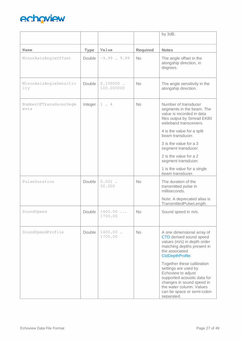
MinorAxisAngleOffset Double -9.99 … 9.99 No The angle offset in the alongship direction, in degrees.
MinorAxisAngleSensitiv
ity Double 0.100000 …
100.000000 No The angle sensitivity in the
alongship direction.
NumberOfTransducerSegm
ents
Integer 1 … 4 No Number of transducer segments in the beam. The value is recorded in data files output by Simrad EK80 wideband transceivers.
4 is the value for a split beam transducer.
3 is the value for a 3 segment transducer.
2 is the value for a 2 segment transducer.
1 is the value for a single
beam transducer.
PulseDuration Double 0.001 …
50.000
No The duration of the transmitted pulse in milliseconds.
Note: A deprecated alias is TransmittedPulseLength.
SoundSpeed Double 1400.00 ...
1700.00
No Sound speed in m/s.
SoundSpeedProfile Double 1400.00 …
1700.00 No A one dimensional array of
CTD derived sound speed values (m/s) in depth order matching depths present in the associated CtdDepthProfile.
Together these calibration settings are used by Echoview to adjust supported acoustic data for changes in sound speed in the water column. Values can be space or semi-colon separated.

Echoview Data File Format Page 28 of 49
Name Type Value Required Notes
Temperature Double -10.000 …
100.000
No The temperature of the water
column, in degrees Celsius.
TransducerGain Double 1.0000 …
99.0000
No The gain (dB) for the transducer.
TransmittedPower Double 1.00000 …
30000.00000
No Transmitted power (Watts).
TRFactor Double 0.0000 …
1000.0000
No The transmit-receive factor (dB) for the transducer.
TwoWayBeamAngle Double -99.000000
...
-1.000000
No Equivalent two-way beam angle, in dB re 1 Steradian.
These attributes may be specified under the MultibeamPing and MultibeamAnglePing Packet. The
attributes are used for multibeam pings with data types of Sv, TS, unspecified dB and angular position.
Name Type Value Required Notes
AbsorptionCoefficient Double 0.0000000 …
100.0000000 No Absorption coefficient in
dB/m.
Note: AbsorptionCoefficient is included in a multibeam EVD export but is not used to derive multibeam variables. The setting may be required and used by Echoview operators.
CalibrationOffset Double -99.900 …
99.900
No An offset (dB) applied to all beams and is used in the calculation of multibeam Sv data.
Exported sample value = sample_value – CalibrationOffset – BeamOffsets(Beam)

Echoview Data File Format Page 29 of 49
Name Type Value Required Notes
BeamOffsets Double -99.00 …
99.00
No An array of offsets (dB)
that is applied per-beam and is used in the calculation of multibeam Sv data.
See (Multibeam ping)
CalibrationOffset, Exported sample value.
SoundSpeed Double 1400.00 ...
1700.00
No Sound speed in m/s.
Examples
<Packet Type="SinglebeamPing">
<Calibration AbsorptionCoefficient="0.0509870" Frequency="200.00"
MinorAxis3dBBeamAngle="6.70" MajorAxis3dBBeamAngle="6.31"
TransmittedPulseLength="0.128" SoundSpeed="1491.35" TwoWayBeamAngle="-
20.700001" CalibrationOffsetSv="0.000" CalibrationOffsetTs="0.000"
TransducerGain="24.8700" TransmittedPower="120.00000"/>
<Packet Type="MultibeamPing">
<Calibration AbsorptionCoefficient="1.0" SoundSpeed="1510.70"/>
<Packet Type="MultibeamPing">
<Calibration CalibrationOffset="1.0" BeamOffsets="0.00 1.00 2.00 3.00 4.00
5.00 6.00 7.00 8.00 9.00 10.00 11.00 12.00 13.00 14.00 15.00 16.00 17.00
18.00 19.0"/>
<Packet Type="SinglebeamPing">
<Parameters Time="05/07/2009 11:13:30.2350" Transducer="1" Channel="0"
Source="ctd single: Sv raw pings T1"/>
<Calibration AbsorptionCoefficient="0.0092819" Frequency="38.0"
PulseDuration="1.024" SoundSpeed="1498.09" TwoWayBeamAngle="-20.6"
MinorAxis3dbBeamAngle="7.0" MajorAxis3dbBeamAngle="6.97"
TransducerGain="25.32" TransmittedPower="2000.0"
MinorAxisAngleOffset="0.02" MajorAxisAngleOffset="0.05"
MinorAxisAngleSensitivity="21.9" MajorAxisAngleSensitivity="21.9"
CtdDepthProfile="0.00 600.0" SoundSpeedProfile="1400.00 1700.0"/>

Echoview Data File Format Page 30 of 49
11 PingData Element
Tag
PingData
Description
All ping Packets must include a PingData element, as it contains the sample data for the ping. The format
for a PingData element should be the opening <PingData> tag (including parameters), followed by the
ping’s sample data, written in binary, little-endian, format. The samples should be written in order from the shortest range to the longest. The element needs to be closed by the </PingData> tag.
Care should be taken that the size of each sample value matches the SamplePrecision attribute. For
example:
• if SamplePrecision is Double then each binary sample should be 8 bytes
• if SamplePrecision is Float then each binary sample should be 4 bytes
Note that for SinglebeamAnglePing data there are two values per sample, the Minor axis (Alongship) value followed by the Major axis (Athwartship) value.
The ResultDataType attribute may be used to specify multiple values to generate, when the EVD file is
added to an Echoview fileset. See also Power equations.
For example: …StorageDataType=”Power” ResultDataType=”Sv, TS”…
MultibeamPing data contains multiple values for each range sample, but in this case the number of values is defined by the BeamCount attribute, which must be specified in the BeamAngles element. The data is then
written out as beam 0 – beam n for the first range value, then beam 0 – beam n for the second range value etc.
The opening tag contains several attributes which describe the data to Echoview, and these attributes must be specified.
Compression
Binary sample data may be compressed to a specified SamplePrecision Compression Quality. For
example:
• SamplePrecision = “Double” and indicates No compression.
• SamplePrecision = “SingleTarget” and indicates No compression.
• SamplePrecision = “Boolean” and indicates No compression.
• SamplePrecision = “CompressedBoolean” and indicates Boolean compression.
• SamplePrecision = “CompressedDouble” and indicates Highest (Lossless) Quality.
• SamplePrecision = “CompressedFloat” and indicates High Quality.
The attribute CompressedByteCount is required to read the compressed data. See also Compression
algorithms.

Echoview Data File Format Page 31 of 49
Attributes
Name Type Value Packet use Notes
ResultDataType String Sv,
TS,
Power,
Angle,
UnspecifiedDb,
SingleTarget,
Boolean
MultibeamAnglePing
MultibeamPing
SinglebeamAnglePing
SinglebeamPing
The type of ping data to be
generated when loaded in Echoview. Note that multiple values specified in one string are supported for SinglebeamPing Packets,
E.g. “TS Sv”.
See the Calibration element for values used in Power to Sv and Power to TS conversion.
StorageDataType String Sv,
TS,
Power,
Angle,
UnspecifiedDb,
SingleTarget,
Boolean
MultibeamAnglePing
MultibeamPing
SinglebeamAnglePing
SinglebeamPing
The type of the ping data as it is stored in the file.
Name Type Value Packet use Notes
CompressedByteCount Integer 1 ... n MultibeamAnglePing
MultibeamPing
SinglebeamAnglePing
SinglebeamPing
The number of compressed bytes present in the PingData element
This attribute is required
when SamplePrecision
is CompressedDouble or CompressedFloat.

Echoview Data File Format Page 32 of 49
Name Type Value Packet use Notes
MajorAxisSteeredAngle Real Decimal degrees
with a precision
up to 10 decimal
places.
Optional for
SinglebeamAnglePing
SinglebeamPing
Can be used for
single beam variables derived from multibeam data.
Represents the
major-axis steered angle for the beam. Echoview only supports a steered angle from the first ping.
MinorAxisSteeredAngle Real Decimal degrees
with a precision
up to 10 decimal
places.
Optional for
SinglebeamAnglePing
SinglebeamPing
Can be used for single beam variables derived from multibeam data.
Represents the minor-axis steered angle for the beam. Echoview only supports a steered angle from the first ping.
SampleCount Integer 0 ... n MultibeamAnglePing
MultibeamPing
SinglebeamAnglePing
SinglebeamPing
The number of samples in this ping.
SamplePrecision String Float,
Double,
Boolean,
CompressedDouble,
CompressedFloat,
CompressedBoolean,
SingleTarget
MultibeamAnglePing
MultibeamPing
SinglebeamAnglePing
SinglebeamPing
The precision of the sample data values.
Binary sample data may be compressed to a Compression Quality.
See also PingData element: Compression.
Note: Echoview 9
EVD files that use deprecated low and medium compression can be read.

Echoview Data File Format Page 33 of 49
Name Type Value Packet use Notes
StartRange Double
Positive real MultibeamAnglePing
MultibeamPing
SinglebeamAnglePing
SinglebeamPing
The start range (m) of the first sample in this ping.
StopRange Double
Positive real MultibeamAnglePing
MultibeamPing
SinglebeamAnglePing
SinglebeamPing
The end range (m) of the last sample in this ping.
Examples
<Packet Type="SinglebeamPing">
<PingData ResultDataType="Sv" StorageDataType="Power"
SamplePrecision="Double" StartRange="0.02" StopRange="99.95"
SampleCount="2094">BINARY PING DATA</PingData>
…
<Packet Type="MultibeamPing">
<PingData ResultDataType="Sv" StorageDataType="Sv" SamplePrecision="Float"
StartRange="0.046" StopRange="499.992" SampleCount="5319">BINARY PING
DATA</PingData>
…
<Packet Type="MultibeamAnglePing">
<PingData ResultDataType="Angle" StorageDataType="Angle"
SamplePrecision="Float" StartRange="0.096685" StopRange="749.983992"
SampleCount="3878">BINARY PING DATA</PingData>
…
<Packet Type="SinglebeamAnglePing">
<PingData ResultDataType="Angle" StorageDataType="Angle"
SamplePrecision="CompressedFloat" StartRange="0.0469961599"
StopRange="497.7363293033" SampleCount="5295" CompressedByteCount="48578"
MinorAxisSteeredAngle="0.0" MajorAxisSteeredAngle="-44.306098938">BINARY
PING DATA</PingData>
…
<Packet Type="MultibeamPing">
<PingData ResultDataType="Sv" StorageDataType="Sv"
SamplePrecision="CompressedFloat" StartRange="0.0469961599"
StopRange="499.9921449776" SampleCount="5319" CompressedByteCount="373413">
BINARY PING DATA</PingData>

Echoview Data File Format Page 34 of 49

Echoview Data File Format Page 35 of 49
<Packet Type="SinglebeamAnglePing">
<PingData ResultDataType="Angle" StorageDataType="Angle"
SamplePrecision="CompressedFloat" StartRange="0.0469961599"
StopRange="499.9921449776" SampleCount="5319" CompressedByteCount="47124"
MinorAxisSteeredAngle="0.0" MajorAxisSteeredAngle="22.7203216553">BINARY
PING DATA</PingData>
…
<Packet Type="SinglebeamPing">
<PingData ResultDataType="SingleTarget" StorageDataType="SingleTarget"
SamplePrecision="SingleTarget" StartRange="0.006" StopRange="29.9939999243"
SampleCount="4">BINARY PING DATA</PingData>
…
<Packet Type="SinglebeamPing">
<PingData ResultDataType="Boolean" StorageDataType="Boolean"
SamplePrecision="CompressedBoolean" StartRange="0.006"
StopRange="29.9939999243" SampleCount="2499" CompressedByteCount="20">
BINARY PING DATA</PingData>
…
<Packet Type="MultibeamPing">
<PingData ResultDataType="Boolean" StorageDataType="Boolean"
SamplePrecision="CompressedBoolean" StartRange="0.0" StopRange="103.224"
SampleCount="782" CompressedByteCount="790>BINARY PING DATA</PingData>

Echoview Data File Format Page 36 of 49
12 BeamAngles Element
Tag
BeamAngles
Description
All MultibeamPing Packets must include a BeamAngles element, which describes the angular position for
each beam of the sample data. This element supports two modes, depending on the BeamAngleMode
attribute – Constant and Variable. In Constant mode the angles for each beam are calculated using the
number of beams and the beam spread, assuming they are evenly spaced. In Variable mode the angle for
each beam is individually specified.
The format for a BeamAngles element should begin with the opening <BeamAngles> tag, and finish with the
</BeamAngles> closing tag. If the BeamAngleMode attribute is Variable then the opening tag should be
immediately followed by the beam angles, written in binary, little-endian, format.
Each beam angle should be in double precision taking up 8 bytes, and should be written in the same order as the data in the PingData element. If the BeamAngleMode is Constant then no data needs to be written
between the opening and closing tags.
Note: Multibeam tilt and multibeam bearing are specified under the Parameters element.
Attributes
Name Type Value Required Notes
BeamCount Integer 1 ... n Yes The number of beams within each ping.
BeamSpread Double 0.0000000000 …
360.0000000000
Yes The angular spread of the beam fan, in degrees.
BeamAngleMode String Constant,
Variable
Yes The mode for determining the beam angles.
Where BeamAngleMode=”Variable”,
Binary Beam Angle data should be written in radians. And beam angles should be written starting from the smallest to the largest angle.
Examples
<Packet Type="MultibeamAnglePing">
<BeamAngles BeamCount="21" BeamSpread="70.979"
BeamAngleMode="Variable">BINARY BEAM ANGLE DATA</BeamAngles>
</Packet>
<Packet Type="MultibeamAnglePing">
<BeamAngles BeamCount="21" BeamSpread="70.979"
BeamAngleMode="Constant"></BeamAngles>
</Packet>
See also Complete Packet Examples: MultibeamPing H-mode data.

Echoview Data File Format Page 37 of 49
13 BeamsWithData Element
Tag
BeamsWithData
Description
Multibeam pings can become very large due to the number of samples present in each beam. This is
necessary if all the beams contain useful data, but for some instruments only specific beams contain data while the others are empty. In this case it is useful to specify which beams have data, and then only write this data to the ping data element.
The BeamsWithData element is optional, and should only be specified when such a situation arises. It
consists of the opening <BeamsWithData> tag followed immediately by a series of booleans written as 8 bit
binary values (in little endian), and then the closing </BeamsWithData> tag. There must be one Boolean
value per beam, a value of true indicates that this beam has data, false indicates there is no data.
The following PingData elements will contain data only for the beams marked as having data. For example, a
400 beam echosounder with data in every other beam would have a BeamsWithData element with a
BeamCount of 400, a BeamAngles element with a BeamCount of 400 and 200 entries per beam in the
PingData element.
The BeamsWithData element must be written before the PingData element.
Attributes
Name Type Value Required Notes
BeamCount Integer 1 ... n Yes The number of beams within each ping.
Example
<BeamsWithData BeamCount="400">BINARY BOOLEAN DATA</BeamsWithData>

Echoview Data File Format Page 38 of 49
14 SingleTarget Element
Tag
SingleTarget
Description
Single target data may be recorded within the PingData element of SinglebeamPing Packets. Each single
target is specified by a <SingleTarget … /> element. SingleTarget attributes are specified within the
element.
When using the SingleTarget element, associated PingData attributes must be specified.
Echoview exports single target data to the Echoview Data File Format.
The exported values cover single target data that may originate from:
• Echoview single target detection operators.
• Instrument single target detections saved to file.
• Single target data derived from targets found with Echoview multibeam target detection.
Note: Absent (Real) values associated with multibeam target detection are recorded as -9.9e+37.
Attributes
Name Type Value Required Notes
Area Real Squared centimeters.
No The estimated sample area for a single target derived from a target found with multibeam target detection.
Compactness Real Unitless ratio No The estimated sample compactness for a single target derived from a target found with multibeam target detection.
𝐶𝑜𝑚𝑝𝑎𝑐𝑡𝑛𝑒𝑠𝑠 = (𝑇𝑎𝑟𝑔𝑒𝑡 𝑝𝑒𝑟𝑖𝑚𝑒𝑡𝑒𝑟)2
4𝜋 ∗ 𝑇𝑎𝑟𝑔𝑒𝑡 𝑎𝑟𝑒𝑎
CompTS Real dB Yes Single target compensated TS value.
CompTS = UncompTS + Correction(
calculated by a Beam compensation model)
Where UncompTS is the single target
TS (dB) value.
Beam compensation is applied to a TS value to correct for the variation of response in the transducer beam.
A Beam compensation model, uses mathematics to emulate the transducer beam pattern and can be used to estimate what the TS would be if the target lay centrally in the beam. Models have limits to their validity. Predictions outside the validity limits can be unreliable.

Echoview Data File Format Page 39 of 49
Name Type Value Required Notes
DetectionMethod String Unknown,
Multibeam, SinglebeamMethod1, SinglebeamMethod2, SplitbeamMethod1, SplitbeamMethod2, WidebandMethod2, WidebandPulseCompressed, FurunoFCV
Yes Specifies the single target detection
method for the single target data:
Unknown = Unknown method.
Multibeam = Single target derived from multibeam target detection data.
SinglebeamMethod1 = Single target detection – single beam (method 1) operator.
SinglebeamMethod2 = Single target detection – single beam (method 2) operator.
SplitbeamMethod1 – Single target detection – split beam (method 1) operator.
SplitbeamMethod2 = Single target detection -split beam (method 2) operator.
WidebandMethod2 = Single target detection – wideband operator.
WidebandPulseCompressed = Single target detection – wideband operator. This string is used for EVD single target data output by Echoview 10, under the deprecated attribute PulseCompressed.
FurunoFCV = Single target detection – Furuno FCV-30 operator.
The value for DetectionMethod is used by Echoview when handling of single target samples.
IntStatus Integer -1, 0, 1, 2, 3, 4 Yes Specifies the Echoview status for a single target:
-1 = Error
0 = Present
1 = Single target is excluded by Threshold settings on the Data* page
2 = Single target is excluded by Filter settings on the Data* page
3 = Single target is excluded by Exclusion settings on the Analysis* page
4 = Single target is outside the selected region
*Refers to the Data and Analysis pages on the Variable Properties dialog box.

Echoview Data File Format Page 40 of 49
Name Type Value Required Notes
IntTargetClass Integer Integer Yes The Echoview single target Target
class.
0 corresponds to the Unclassified Targets class.
IntTargetClass integers are
assigned in order from Unclassified Targets.
Length Real Centimeters. No Single target Target length as calculated by the equation used by the Echoview Target Length Calculator operator.
CompTS = A log(L) + B
Where:
CompTS is the compensated TS value of the single target.
L (cm) is the length of the target.
A is the target species Slope.
B is the target species Intercept.
Species data for A and B are published
in fisheries acoustic studies. For more information refer to the Echoview Help file -Target Length Calculator algorithm.
LengthAcrossBeams Real Centimeters No The estimated target length across beams for a single target derived from a target found with multibeam target detection.
LengthUncompensated Real Meters No Single target Target length as calculated by the equation used by the Echoview Target Length Calculator operator.
UncompTS = A log(L) + B
UncompTS is the uncompensated TS value of the single target.
A, B, L are defined as for single target
Length (see above)
ManualLength Real Centimeters No The manually measured and stored target length for a single target derived from a target found with multibeam target detection.
MajorAxisAngle Real Decimal degrees Yes Single target major axis angle.
MidpointArea Squared Centimeters
No The estimated edge-midpoint sample area for a single target derived from a target found with multibeam target detection.

Echoview Data File Format Page 41 of 49
Name Type Value Required Notes
MidpointCompactness Unitless ratio No The estimated edge-midpoint sample
compactness for a single target derived from a target found with multibeam target detection.
MidpointPerimeter Centimeters No The estimated edge-midpoint sample perimeter for a single target derived from a target found with multibeam target detection.
MinorAxisAngle Real Decimal degrees Yes Single target minor axis angle.
Perimeter Centimeters No The estimated edge-sample perimeter for a single target derived from a target found with multibeam target detection.
PLDL Real dB Yes Single target Pulse Length Determination Level (PLDL).
The PLPD defines the number of decibels below the peak value of a detected single target pulse.at which the pulse length is determined during single target detection.
PulseCompressed Boolean
True, False Yes Indicates single targets derived from pulse compressed wideband data.
Note: Echoview 11 can read EVD files that use this attribute. However Echoview 11 does not output the PulseCompressed attribute. The attribute DetectionMethod is used instead.
PulseLengthNormAtPLD
L
Real Unitless ratio Yes The length of a single target pulse (at the PLDL) normalized to the transmitted pulse length.
PulseLengthNorm6dB Real Unitless ratio Yes The length of a single target pulse (at 6dB down from the peak) normalized to the transmitted pulse length
PulseLengthNorm18dB Real Unitless ratio Yes The length of a single target pulse (at 18dB down from the peak) normalized to the transmitted pulse length
PulseLengthNorm12dB Real Unitless ratio Yes The length of a single target pulse (at 12dB down from the peak) normalized to the transmitted pulse length
PulseStartNormPLDL Real Unitless ratio Yes Distance between the start and peak of a single target pulse (at the PLDL) normalized to the transmitted pulse length.
PulseStartNorm6dB Real Unitless ratio Yes Distance between the start and peak of a single target pulse (at the PulseLengthNorm6dB) normalized to the transmitted pulse length.

Echoview Data File Format Page 42 of 49
Name Type Value Required Notes
PulseStartNorm12dB Real Unitless ratio Yes Distance between the start and peak of
a single target pulse (at the PulseLengthNorm12dB) normalized to the transmitted pulse length.
PulseStartNorm18dB Real Unitless ratio Yes Distance between the start and peak of a single target pulse (at the PulseLengthNorm18dB) normalized to the transmitted pulse length.
Range Real Meters Yes Single target range (m)
RangeExtent Real Centimeters No Target range extent is calculated as the
range difference between the shallowest sample and the deepest sample for a single target derived from a target found with multibeam target detection
SDMajorAxis Real Decimal degrees Yes The maximum standard deviation of the Major-axis angles of all samples within a single target pulse determined at the PLDL (degrees).
SDMinorAxis Real Decimal degrees Yes The maximum standard deviation of the Minor-axis angles of all samples within a single target pulse determined at the PLDL (degrees).
TargetOrientation Real Decimal degrees No The angle between the target Length derived axis and the line perpendicular to the transducer axis. The target Length axis is defined as the line joining the two most distant samples for a single target derived from a target found with multibeam target detection.
UncompTS Real dB Yes Uncompensated TS value of the single target.
Variation Real Unitless No The target intensity variation of the samples for a single target derived from a target found with multibeam target detection.
𝑉𝑎𝑟𝑖𝑎𝑡𝑖𝑜𝑛 = 𝜎
𝜇
σ is the standard deviation of the intensity of the samples in the target.
μ is mean intensity of samples in the target.

Echoview Data File Format Page 43 of 49
Example
Single target data
<SingleTarget Range="2.796396" CompTS="-43.738220" UncompTS="-45.582551"
MinorAxisAngle="1.875000" MajorAxisAngle="-0.602679" Length="-9.9e+37"
PulseLengthNormAtPLDL="1.500000" PLDL="6.000000" PulseLengthNorm6dB="1.500000"
PulseLengthNorm12dB="2.750000" PulseLengthNorm18dB="4.000000"
SDMinorAxis="0.463482" SDMajorAxis="0.597519" PulseStartNorm6dB="-0.500000"
PulseStartNorm12dB="-1.000000" PulseStartNorm18dB="-1.500000"
PulseStartNormPLDL="-0.500000" IntSamplesInPulse="7" Status="0" TargetClass="0"
LengthUncompensated="-9.9e+37" LengthAcrossBeams="-9.9e+37" ManualLength="-
9.9e+37" Perimeter="-9.9e+37" MidpointPerimeter="-9.9e+37" Area="-9.9e+37"
MidpointArea="-9.9e+37" Thickness="-9.9e+37" Compactness="-9.9e+37"
MidpointCompactness="-9.9e+37" Variation="-9.9e+37" RangeExtent="-9.9e+37"
TargetOrientation="-9.9e+37"/>
Single target data with deprecated attribute PulseCompressed
<SingleTarget Range="2.936000" CompTS="-89.153188" UncompTS="-91.970168"
MinorAxisAngle="-0.496933" MajorAxisAngle="-2.229737" Length="-9.9e+37"
PulseCompressed="True" PulseLengthNormAtPLDL="1.038624" PLDL="6.000000"
PulseLengthNorm6dB="1.038624" PulseLengthNorm12dB="1.557936"
PulseLengthNorm18dB="9.347614" SDMinorAxis="0.295917" SDMajorAxis="0.265903"
PulseStartNorm6dB="-0.519312" PulseStartNorm12dB="-0.519312"
PulseStartNorm18dB="-0.519312" PulseStartNormPLDL="-0.519312"
IntSamplesInPulse="3" Status="0" TargetClass="0" LengthUncompensated="-9.9e+37"
LengthAcrossBeams="-9.9e+37" ManualLength="-9.9e+37" Perimeter="-9.9e+37"
MidpointPerimeter="-9.9e+37" Area="-9.9e+37" MidpointArea="-9.9e+37" Thickness="-
9.9e+37" Compactness="-9.9e+37" MidpointCompactness="-9.9e+37" Variation="-
9.9e+37" RangeExtent="-9.9e+37" TargetOrientation="-9.9e+37"/>
Single target data with attribute DetectionMethod
<SingleTarget Range="2.389725" CompTS="-40.654405" UncompTS="-42.325190"
MinorAxisAngle="0.871865" MajorAxisAngle="1.691374" Length="-9.9e+37"
DetectionMethod="SplitbeamMethod2" PulseLengthNormAtPLDL="1.347368"
PLDL="6.000000" PulseLengthNorm6dB="1.347368" PulseLengthNorm12dB="1.852632"
PulseLengthNorm18dB="2.357895" SDMinorAxis="0.014883" SDMajorAxis="0.025688"
PulseStartNorm6dB="-0.673684" PulseStartNorm12dB="-1.010526"
PulseStartNorm18dB="-1.010526" PulseStartNormPLDL="-0.673684"
IntSamplesInPulse="9" Status="0" TargetClass="0" LengthUncompensated="-9.9e+37"
LengthAcrossBeams="-9.9e+37" ManualLength="-9.9e+37" Perimeter="-9.9e+37"
MidpointPerimeter="-9.9e+37" Area="-9.9e+37" MidpointArea="-9.9e+37" Thickness="-
9.9e+37" Compactness="-9.9e+37" MidpointCompactness="-9.9e+37" Variation="-
9.9e+37" RangeExtent="-9.9e+37" TargetOrientation="-9.9e+37"/>

Echoview Data File Format Page 44 of 49
15 Complete Packet Examples
SinglebeamPing with TRFactor
<Packet Type="TransducerList">
<Transducer ID="1" Echosounder="Sonic"/>
</Packet>
<Packet Type="SinglebeamPing">
<Parameters Time="03/07/2013 12:44:29.0000" Transducer="1" Channel="0"
Source="Fileset1: Sv split beam pings T1"/>
<Calibration AbsorptionCoefficient="0.0094" Frequency="38.0"
TransmittedPulseLength="0.3" SoundSpeed="1400.0" TwoWayBeamAngle="-19.1"
TRFactor="55.5"/>
<PingData ResultDataType="Sv" StorageDataType="Power"
SamplePrecision="Double" StartRange="0.0175" StopRange="100.0125"
SampleCount="2857">BINARY PING DATA</PingData>
<Packet>
SinglebeamPing
<Packet Type="TransducerList">
<Transducer ID="1" Echosounder="SimradEK60Raw"/>
</Packet>
<Packet Type="SinglebeamPing">
<Parameters Time="23/03/2006 23:18:18.4230" Transducer="1" Channel="0"
Source="Fileset1: Sv raw pings T1"/>
<Calibration AbsorptionCoefficient="0.0097472" Frequency="38.0"
TransmittedPulseLength="1.024" SoundSpeed="1500.0" TwoWayBeamAngle="-20.6"
MinorAxis3dbBeamAngle="7.1" MajorAxis3dbBeamAngle="7.1"
TransducerGain="26.5" TransmittedPower="200.0" MinorAxisAngleOffset="0.0"
MajorAxisAngleOffset="0.0" MinorAxisAngleSensitivity="21.9"
MajorAxisAngleSensitivity="21.9"/>
<PingData ResultDataType="Sv" StorageDataType="Power"
SamplePrecision="Double" StartRange="0.0959999998"
StopRange="249.8879993691" SampleCount="1301">BINARY PING DATA</PingData>
</Packet>

Echoview Data File Format Page 45 of 49
SinglebeamPing Single target data
<Packet Type="SinglebeamPing">
<Parameters Time="26/07/2000 23:52:14.7600" Transducer="1" Channel="0"
Source="Single target detection - split beam (method 2) 1"/>
<Calibration AbsorptionCoefficient="0.0373058" Frequency="120.0"
TransmittedPulseLength="0.064" SoundSpeed="1500.0" TwoWayBeamAngle="-
20.799999" MinorAxis3dbBeamAngle="7.1" MajorAxis3dbBeamAngle="7.1"
TransducerGain="22.8" TransmittedPower="100.0" MinorAxisAngleOffset="0.0"
MajorAxisAngleOffset="0.0" MinorAxisAngleSensitivity="21.0"
MajorAxisAngleSensitivity="21.0"/>
<PingData ResultDataType="SingleTarget" StorageDataType="SingleTarget"
SamplePrecision="SingleTarget" StartRange="0.006" StopRange="29.9939999243"
SampleCount="4">
<SingleTarget Range="2.796396" CompTS="-43.738220" UncompTS="-
45.582551" MinorAxisAngle="1.875000" MajorAxisAngle="-0.602679"
Length="-9.9e+37" PulseLengthNormAtPLDL="1.500000" PLDL="6.000000"
PulseLengthNorm6dB="1.500000" PulseLengthNorm12dB="2.750000"
PulseLengthNorm18dB="4.000000" SDMinorAxis="0.463482"
SDMajorAxis="0.597519" PulseStartNorm6dB="-0.500000"
PulseStartNorm12dB="-1.000000" PulseStartNorm18dB="-1.500000"
PulseStartNormPLDL="-0.500000" IntSamplesInPulse="7" Status="0"
TargetClass="0" LengthUncompensated="-9.9e+37" LengthAcrossBeams="-
9.9e+37" ManualLength="-9.9e+37" Perimeter="-9.9e+37"
MidpointPerimeter="-9.9e+37" Area="-9.9e+37" MidpointArea="-9.9e+37"
Thickness="-9.9e+37" Compactness="-9.9e+37" MidpointCompactness="-
9.9e+37" Variation="-9.9e+37" RangeExtent="-9.9e+37"
TargetOrientation="-9.9e+37"/>
… </PingData>
</Packet>
SinglebeamPing Boolean data
<Packet Type="SinglebeamPing">
<Parameters Time="26/07/2000 23:52:14.7600" Transducer="1" Channel="0"
Source="Target samples bitmap 1"/>
<Calibration AbsorptionCoefficient="0.0373058" Frequency="120.0"
TransmittedPulseLength="0.064" SoundSpeed="1500.0" TwoWayBeamAngle="-
20.799999" MinorAxis3dbBeamAngle="7.1" MajorAxis3dbBeamAngle="7.1"
TransducerGain="22.8" TransmittedPower="100.0" MinorAxisAngleOffset="0.0"
MajorAxisAngleOffset="0.0" MinorAxisAngleSensitivity="21.0"
MajorAxisAngleSensitivity="21.0"/>
<PingData ResultDataType="Boolean" StorageDataType="Boolean"
SamplePrecision="CompressedBoolean" StartRange="0.006"
StopRange="29.9939999243" SampleCount="2499"
CompressedByteCount="25">BINARY PING DATA</PingData>
</Packet>

Echoview Data File Format Page 46 of 49
SinglebeamAnglePing
<Packet Type="TransducerList">
<Transducer ID="1" Echosounder="SimradEK60Raw"/>
</Packet>
<Packet Type="SinglebeamAnglePing">
<Parameters Time="23/03/2006 23:18:18.4230" Transducer="1" Channel="0"
Source="Fileset1: angular position raw pings T1"/>
<Calibration AbsorptionCoefficient="0.0097472" Frequency="38.0"
TransmittedPulseLength="1.024" SoundSpeed="1500.0" TwoWayBeamAngle="-20.6"
MinorAxis3dbBeamAngle="7.1" MajorAxis3dbBeamAngle="7.1"
TransducerGain="26.5" TransmittedPower="200.0" MinorAxisAngleOffset="0.0"
MajorAxisAngleOffset="0.0" MinorAxisAngleSensitivity="21.9"
MajorAxisAngleSensitivity="21.9"/>
<PingData ResultDataType="Angle" StorageDataType="Angle"
SamplePrecision="Float" StartRange="0.0959999998"
StopRange="249.8879993691" SampleCount="1301">BINARY PING DATA</PingData>
</Packet>
MultibeamPing
<Packet Type="MultibeamPing">
<Parameters Time="13/07/2008 04:10:29.9940" Transducer="26" Channel="0"
Source="Fileset1: Sv pings formed beams" PingMode="Multibeam"/>
<Calibration AbsorptionCoefficient="0.0205062" SoundSpeed="1468.63"/>
<BeamAngles BeamCount="21" BeamSpread="95.2161865234" BeamAngleMode="Variable">
BINARY BEAM ANGLE DATA </BeamAngles>
<PingData ResultDataType="Sv" StorageDataType="Sv" SamplePrecision="Float"
StartRange="0.0469961599" StopRange="499.9921449776" SampleCount="5319">
BINARY PING DATA </PingData>
</Packet>
MultibeamPing Boolean data
<Packet Type="MultibeamPing">
<Parameters Time="14/05/1999 23:09:58.4600" Transducer="0" Channel="0"
Source="Region bitmap 1" PingMode="Multibeam"/>
<Calibration/>
<BeamAngles BeamCount="128" BeamSpread="120.0"
BeamAngleMode="Constant"></BeamAngles>
<PingData ResultDataType="Boolean" StorageDataType="Boolean"
SamplePrecision="CompressedBoolean" StartRange="0.0" StopRange="50.2734375"
SampleCount="246" CompressedByteCount="248">BINARY PING DATA</PingData>
</Packet>

Echoview Data File Format Page 47 of 49
MultibeamAnglePing
<Packet Type="TransducerList">
<Transducer ID="26" Echosounder="SimradME70"/>
</Packet>
<Packet Type="MultibeamAnglePing">
<Parameters Time="13/07/2008 04:10:29.9940" Transducer="26" Channel="0"
Source="Fileset1: angular position pings formed beams"
PingMode="Multibeam"/>
<Calibration AbsorptionCoefficient="0.0205062" SoundSpeed="1468.63"/>
<BeamAngles BeamCount="21" BeamSpread="95.2161865234"
BeamAngleMode="Variable"> BINARY BEAM ANGLE DATA </BeamAngles>
<PingData ResultDataType="Angle" StorageDataType="Angle"
SamplePrecision="Float" StartRange="0.0469961599"
StopRange="499.9921449776" SampleCount="5319"> BINARY PING DATA </PingData>
</Packet>
MultibeamPing H-mode data
<Packet Type="TransducerList">
<Transducer ID="16" Echosounder="Simrad SX90, SH90 or SU90"/>
</Packet>
<Packet Type="MultibeamPing">
<Parameters Time="03/11/2011 11:17:44.0910" Transducer="16" Channel="0"
Source="Fileset 1: Sv complex beamformed pings Omni (H-mode)"
PingMode="HMode" TiltAngle="10.008545" Bearing="82.0"/>
<Calibration AbsorptionCoefficient="0.006" SoundSpeed="1492.0"/>
<BeamAngles BeamCount="64" BeamSpread="360.0"
BeamAngleMode="Constant"></BeamAngles>
<PingData ResultDataType="Sv" StorageDataType="Sv"
SamplePrecision="CompressedFloat" StartRange="0.0737644815"
StopRange="60.2655814047" SampleCount="408" CompressedByteCount="84116">
BINARY PING DATA </PingData>
</Packet>

Echoview Data File Format Page 48 of 49
MultibeamPing BeamsWithData
<Packet Type="MultibeamPing">
<Parameters Time="30/05/2008 01:51:04.0080" Channel="0" Source="Fileset1:
Sv beamformed pings" PingMode="HMode" TiltAngle="270.0"/>
<Calibration AbsorptionCoefficient="1.0" SoundSpeed="1500.0"/>
<BeamAngles BeamCount="1600" BeamSpread="360.0000000000"
BeamAngleMode="Constant"></BeamAngles>
<BeamsWithData BeamCount="1600">BINARY BOOLEAN DATA</BeamsWithData>
<PingData ResultDataType="Sv" StorageDataType="Sv" SamplePrecision="Float"
StartRange="0.0" StopRange="4.0677966102" SampleCount="952"> BINARY PING
DATA </PingData>
</Packet>
Position
<Packet Type="Position">
<Parameters Time="28/08/1996 04:40:03.8500" Channel="0" Latitude="-
42.24994303385" Longitude="145.30068359375" Status="Good" Source="Primary
fileset: position GPS fixes"/>
</Packet>
Heading
<Packet Type="Heading">
<Parameters Time="08/11/2009 07:16:04.9450" Channel="0"
Heading="24.200000"/>
</Packet>
DepthLine
<Packet Type="DepthLine">
<Parameters Time="06/07/2009 07:21:39.8760" Channel="0" Depth="221.649004"
Status="Good" Source="Best bottom candidate line pick 1"/>
</Packet>
Distance
<Packet Type="Distance">
<Parameters Time="13/07/2008 04:10:29.9940" Channel="0"
Distance="2944.231000"/>
</Packet>

Echoview Data File Format Page 49 of 49
RangeLine
<Packet Type="RangeLine">
<Calibration Frequency="120.0" SoundSpeed="1463.73"/>
<Parameters Time="06/07/2009 07:21:39.8760" Channel="0" Transducer="2"
Range="121.506993" Status="Good" Source="Fileset1: line data sounder
detected bottom T2"/>
</Packet>