the printing ink manual - link.springer.com978-1-4020-6187-5/1.pdf · the objective of the printing...
TRANSCRIPT

ThePrinting
Ink Manual

ThePrinting
Ink ManualFIFTH EDITION
Edited by
R.H. Leach, R.J. Pierce
E.P. Hickman, M.J. Mackenzie and H.G. Smith

Library of Congress Cataloging-in-Publication Data
ISBN 10 0-948905-81-6
ISBN 13 978-0-948905-81-0
Published by SpringerP.O. Box 17, 3300 AA Dordrecht, The Netherlands.
www.springer.com
First edition 1961Reprinted 1963 (with revisions)Second edition 1969Third edition 1979Reprinted 1984Fourth edition 1988Reprinted 1988, 1989, 1991Fifth edition 1993Reprinted 1999, 2002, 2007
Printed on acid-free paper
All Rights Reserved� 2007 SpringerNo part of the material protected by this copyright notice may be reproduced orutilized in any form or by any means, electronic or mechanical,including photocopying, recording or by any information storage andretrieval system, without written permission from the copyright owner.
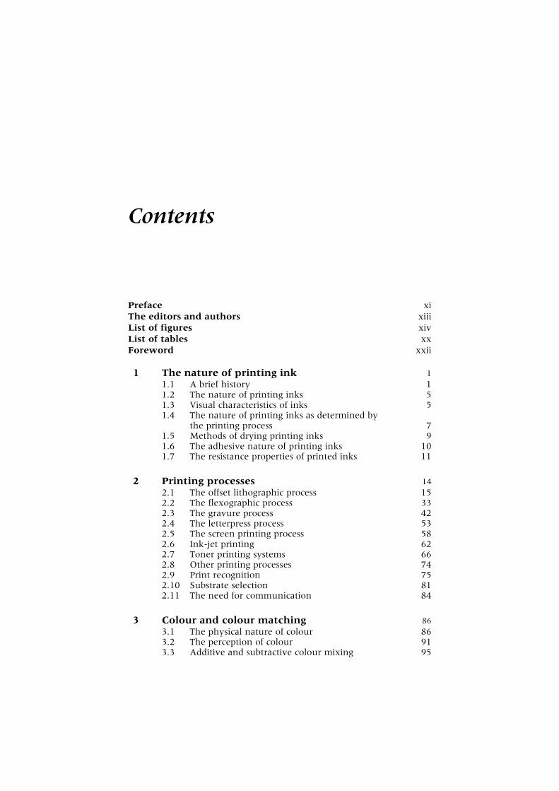
Contents
Preface xi
The editors and authors xiii
List of figures xiv
List of tables xx
Foreword xxii
1 The nature of printing ink 1
1.1 A brief history 11.2 The nature of printing inks 51.3 Visual characteristics of inks 51.4 The nature of printing inks as determined by
the printing process 71.5 Methods of drying printing inks 91.6 The adhesive nature of printing inks 101.7 The resistance properties of printed inks 11
2 Printing processes 14
2.1 The offset lithographic process 152.2 The flexographic process 332.3 The gravure process 422.4 The letterpress process 532.5 The screen printing process 582.6 Ink-jet printing 622.7 Toner printing systems 662.8 Other printing processes 742.9 Print recognition 752.10 Substrate selection 812.11 The need for communication 84
3 Colour and colour matching 86
3.1 The physical nature of colour 863.2 The perception of colour 913.3 Additive and subtractive colour mixing 95
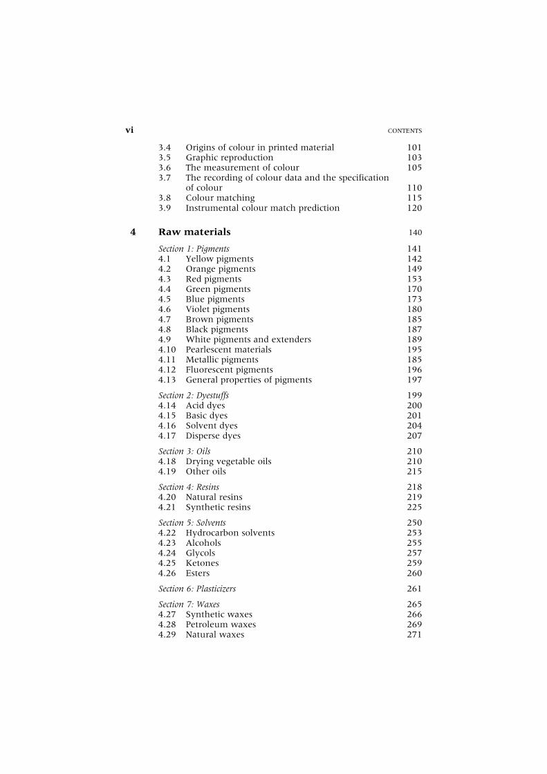
3.4 Origins of colour in printed material 1013.5 Graphic reproduction 1033.6 The measurement of colour 1053.7 The recording of colour data and the specification
of colour 1103.8 Colour matching 1153.9 Instrumental colour match prediction 120
4 Raw materials 140
Section 1: Pigments 1414.1 Yellow pigments 1424.2 Orange pigments 1494.3 Red pigments 1534.4 Green pigments 1704.5 Blue pigments 1734.6 Violet pigments 1804.7 Brown pigments 1854.8 Black pigments 1874.9 White pigments and extenders 1894.10 Pearlescent materials 1954.11 Metallic pigments 1854.12 Fluorescent pigments 1964.13 General properties of pigments 197
Section 2: Dyestuffs 1994.14 Acid dyes 2004.15 Basic dyes 2014.16 Solvent dyes 2044.17 Disperse dyes 207
Section 3: Oils 2104.18 Drying vegetable oils 2104.19 Other oils 215
Section 4: Resins 2184.20 Natural resins 2194.21 Synthetic resins 225
Section 5: Solvents 2504.22 Hydrocarbon solvents 2534.23 Alcohols 2554.24 Glycols 2574.25 Ketones 2594.26 Esters 260
Section 6: Plasticizers 261
Section 7: Waxes 2654.27 Synthetic waxes 2664.28 Petroleum waxes 2694.29 Natural waxes 271
vi CONTENTS

Section 8: Driers 2734.30 Liquid driers 2744.31 Paste driers 275
Section 9: Miscellaneous additives 2764.32 Chelating agents 2764.33 Anti-oxidants 2774.34 Surfactants 2784.35 Deodorants and reodorants 2804.36 Pure chemicals 2804.37 Defoaming agents 2824.38 Laking agents 283
Section 10: Raw materials for radiation curing systems 2844.39 Pigment selection 2844.40 Prepolymers 2854.41 Reactive diluents 2864.42 Photo-initiators 2874.43 Additives and inhibitors 287
Section 11: Health and safety at work 288
5 Letterpress inks 323
5.1 Nature of the process 3235.2 Types of press 3235.3 General characteristics of letterpress inks 3255.4 Physical properties 3265.5 Raw materials 3265.6 Letterpress ink formulation 3305.7 Newspaper inks 3335.8 Inks for packaging 3345.9 Ink-related problems and their possible solution 3365.10 Special purpose applications 339
6 Lithographic inks 342
6.1 General introduction to lithography 3426.2 Cold-set lithographic inks 3536.3 Web-offset heat-set inks 3606.4 Sheet-fed inks for paper and board 3876.5 Three piece tin-printing inks 431
7 Dry offset inks 453
Section 1: Dry offset inks for plastic 4537.1 Drying mechanisms and the influence of the
substrate 4557.2 Formulating principles 4567.3 General characteristics of dry offset inks 4597.4 The future 461
CONTENTS vii

Section 2: Two-piece can decoration 4617.5 Method of print application 4627.6 Ink formulation 4637.7 Ink properties required 4657.8 Printing problems 4667.9 Problem solving 4677.10 Future trends 472
8 Gravure inks 473
8.1 General characteristics 4758.2 Physical properties of inks and their measurement 4838.3 Formulating principles 4908.4 Inks and varnishes for specific end-use applications 5028.5 Printing ink faults 5368.6 Recent developments 540
9 Flexographic inks 547
9.1 General characteristics of the inks 5499.2 Physical properties of flexographic inks and their
measurement 5549.3 Formulating principles 5609.4 Inks and varnishes for specific purposes 5699.5 Ink-related printing problems and possible solutions 5929.6 Recent trends 595
10 Screen inks 599
10.1 Important characteristics of screen inks 59910.2 Requirements of raw materials 60410.3 Inks for paper and board 60710.4 Inks for impervious surfaces 61010.5 Inks for plastic containers 61510.6 Textile inks 61810.7 Transfer inks 62110.8 Overprint varnishes 62210.9 Daylight fluorescent inks 62210.10 Process inks 62310.11 Metallics 62410.12 Speciality screen inks 62610.13 Inks for the electronics industry 62810.14 Ink-related printing problems 63210.15 Recent trends 634
11 Ultra-violet and electron-beam curing systems 636
11.1 Radiation-curing processes 63711.2 Electromagnetic radiation and electron beams 63811.3 Introduction to formulation 64111.4 Advantages and limitations for ultra-violet and
electron-beam inks and varnishes 642
viii CONTENTS
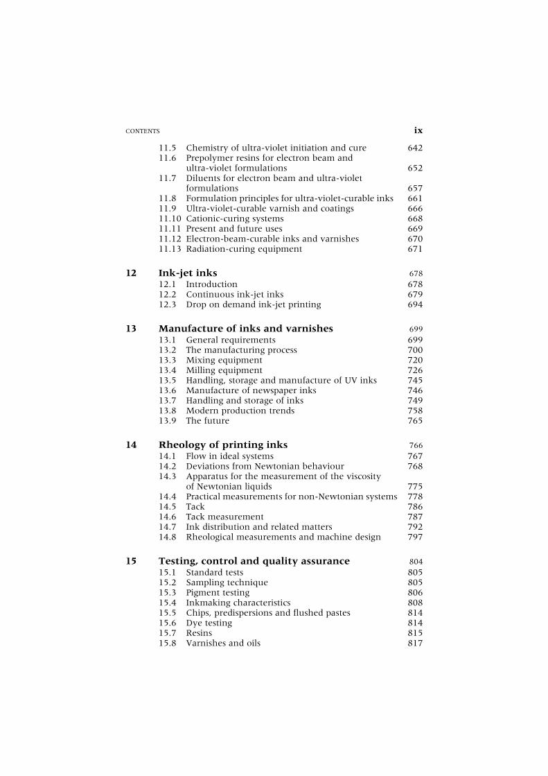
11.5 Chemistry of ultra-violet initiation and cure 64211.6 Prepolymer resins for electron beam and
ultra-violet formulations 65211.7 Diluents for electron beam and ultra-violet
formulations 65711.8 Formulation principles for ultra-violet-curable inks 66111.9 Ultra-violet-curable varnish and coatings 66611.10 Cationic-curing systems 66811.11 Present and future uses 66911.12 Electron-beam-curable inks and varnishes 67011.13 Radiation-curing equipment 671
12 Ink-jet inks 678
12.1 Introduction 67812.2 Continuous ink-jet inks 67912.3 Drop on demand ink-jet printing 694
13 Manufacture of inks and varnishes 699
13.1 General requirements 69913.2 The manufacturing process 70013.3 Mixing equipment 72013.4 Milling equipment 72613.5 Handling, storage and manufacture of UV inks 74513.6 Manufacture of newspaper inks 74613.7 Handling and storage of inks 74913.8 Modern production trends 75813.9 The future 765
14 Rheology of printing inks 766
14.1 Flow in ideal systems 76714.2 Deviations from Newtonian behaviour 76814.3 Apparatus for the measurement of the viscosity
of Newtonian liquids 77514.4 Practical measurements for non-Newtonian systems 77814.5 Tack 78614.6 Tack measurement 78714.7 Ink distribution and related matters 79214.8 Rheological measurements and machine design 797
15 Testing, control and quality assurance 804
15.1 Standard tests 80515.2 Sampling technique 80515.3 Pigment testing 80615.4 Inkmaking characteristics 80815.5 Chips, predispersions and flushed pastes 81415.6 Dye testing 81415.7 Resins 81515.8 Varnishes and oils 817
CONTENTS ix
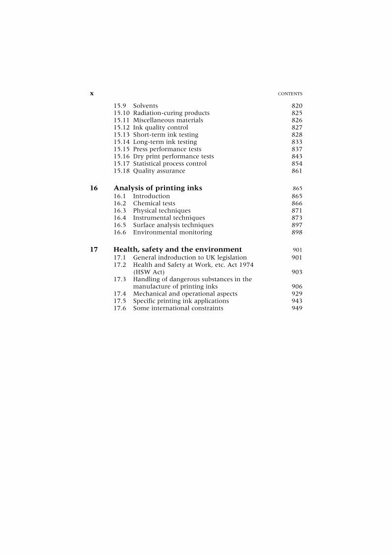
15.9 Solvents 82015.10 Radiation-curing products 82515.11 Miscellaneous materials 82615.12 Ink quality control 82715.13 Short-term ink testing 82815.14 Long-term ink testing 83315.15 Press performance tests 83715.16 Dry print performance tests 84315.17 Statistical process control 85415.18 Quality assurance 861
16 Analysis of printing inks 865
16.1 Introduction 86516.2 Chemical tests 86616.3 Physical techniques 87116.4 Instrumental techniques 87316.5 Surface analysis techniques 89716.6 Environmental monitoring 898
17 Health, safety and the environment 901
17.1 General indroduction to UK legislation 90117.2 Health and Safety at Work, etc. Act 1974
(HSW Act) 90317.3 Handling of dangerous substances in the
manufacture of printing inks 90617.4 Mechanical and operational aspects 92917.5 Specific printing ink applications 94317.6 Some international constraints 949
x CONTENTS

Preface
The first edition of the Printing Ink Manual was published by the Society ofBritish Printing Ink Manufacturers in 1961 to fill the need for anauthorative textbook on printing technology, which would serve bothas a training manual and a reliable reference book for everyday use. Thebook soon became established as a standard source of information onprinting inks and reached its fourth edition by 1988. This, the fifthedition, is being published only five years later, so rapid has been thedevelopment in technology.
The objective of the Printing Ink Manual remains unchanged. It is apractical handbook designed for use by everyone engaged in the printingink industry and the associated industries. It provides all the informationrequired by the ink technical for the day-to-day formulation of printinginks. It supplies the factory manager with details of the latest equipmentand manufacturing methods, including large-scale production, and givesguidance on achieving quality assessment and total quality managementspecifications. Care has been taken to maintain the value of the Manualfor training both technical personnel and others who require some know-ledge of inks. Readers with little scientific knowledge will not find diffi-culty in using the Manual, but sufficient chemistry and physics have beenincluded to provide an explanation of the underlying principles andtheories governing the behaviour of inks for use by the advanced tech-nologist. Suppliers of raw materials, substrate manufacturers, printersand print users will find the book a valuable source of information.
Both environmental issues and quality management concepts havegrown in significance and are having a marked effect on ink developmentand manufacture. These trends are covered in detail, incorporating thelatest practices in a continuously changing situation. Many chapters havebeen written by authors working for international companies, ensuringthat the contents will include the widest international practices. Legisla-tion, mainly European and from the United States, together with speci-fications set by world-wide end-users have established printing ink as atruly international product and the Manual will consequently be of helpto a very wide readership.
This edition contains many significant changes. The lithographic chap-ter has been expanded to cover in more detail cold-set, heat-set, sheet-fed

paper and metal-decorating inks; dry-offset inks have now been allocateda separate chapter and have been divided into inks for plastics and two-piece inks. Analysis has been separated from quality control and both arecovered in individual chapters. A new chapter has been introduceddealing with ink-jet inks. All the remaining chapters have been reviewed,updated and expanded where needed.
R.H. LeachR.J. Pierce
ACKNOWLEDGEMENT
The editors wish to acknowledge the valuable help from P.W.G.Seabrook, Director of the Society of British Printing Ink Manufacturers.Without his organizational skills their tight target schedule could nothave been met.
xii PREFACE

The editors and authors
Editors
Dr R.H. Leach Joint Editor-in-ChiefMr R.J. Pierce Joint Editor-in-ChiefMr E.P. Hickman Technical Consultant, Manders Printing InksMr M.J. Mackenzie Technical Director, Usher-Walker Printing Inks LtdDr H.G. Smith Technical Director (Oil Inks),
BASF Coatings þ Inks Ltd
Authors
Chapter 1 Dr R.H. LeachMr R.J. Pierce
Chapter 2 Mr J.W. Birkenshaw PIRA InternationalChapter 3 Mr J.F. Brown Mander-Kidd (UK) Ltd
Mr K. Lau Datacolour InternationalChapter 4 Mr M. Clayton Sun Chemical LtdChapter 5 Mr G.B. Burdall Usher-Walker plcChapter 6 Mr G.B. Burdall Usher-Walker plc
Mr D. Owen Sun Chemical LtdDr R. Paradine Carnaud Metalbox Technology plc
Chapter 7 Mr J.E. Kenee Can Print LtdMr P. O’Flynn Coates Lorilleux Ltd
Chapter 8 Mr B. Hancock BASF Coatings þ Inks LtdChapter 9 Mr F.C. Wyatt Coates Lorilleux LtdChapter 10 Mr M.J. Barker Dane and Company LtdChapter 11 Mr I. Hargreaves Sun Chemical LtdChapter 12 Dr A. Hudd Domino Amjet LtdChapter 13 Mr M.J. Heath Coates Lorilleux LtdChapter 14 Mr G.A. Tabbernor Manders Oil Inks LtdChapter 15 Mr P. Simpson Manders Oil Inks LtdChapter 16 Mr D. Easterby Coates Lorilleux LtdChapter 17 Mr J.L. Orpwood Coates Lorilleux LtdIndex Mr P. Greene PIRA International

List of figures
Fig. 2.1 Single-colour rotaryoffset machine.
Fig. 2.2 Two-colour rotary offsetmachine.
Fig. 2.3 Blanket-to-blanketperfector press.
Fig. 2.4 A typical completefour-colour press.
Fig. 2.5 Blanket-to-blanketperfector press units.
Fig. 2.6 Web printing units withcommon-impressioncylinders.
Fig. 2.7 Three-cylinderprinciple.
Fig. 2.8 (a) A plate scanner.(b) Press console.
Fig. 2.9 Dot gain characteristiccurve.
Fig. 2.10 Real dot gaincharacteristic curves.
Fig. 2.11 Cross-section throughsimple ink duct.
Fig. 2.12 Flexographic printingunit.
Fig. 2.13 Laser-engraved ceramicanilox roller.
Fig. 2.14 Reverse angle doctorblade.
Fig. 2.15 An enclosed ink chambersystem.
Fig. 2.16 Configuration of typicalstack press.
Fig. 2.17 A stack press.
Fig. 2.18 Common-impressionpress.
Fig. 2.19 A gravure printing unit.Fig. 2.20 Doctor blade angles.Fig. 2.21 A gravure screen.Fig. 2.22 Gelatine layer on copper
cylinder.Fig. 2.23 The etched surface.Fig. 2.24 Platen presses.Fig. 2.25 Flat-bed cylinder press
arrangement.Fig. 2.26 Etching a letterpress
plate.Fig. 2.27 Basic screen press
arrangement.Fig. 2.28 Cylinder press.Fig. 2.29 Continuous ink-jet
printhead.Fig. 2.30 Hertz ink-jet system.Fig. 2.31 Impulse or drop on
demand printhead.Fig. 2.32 Canon bubble-jet.Fig. 2.33 Schematic layout of
electrophotographicprinter.
Fig. 2.34 Photoconductorsensitivity.
Fig. 2.35 Ion-deposition printer.Fig. 2.36 Electrostatic printer.Fig. 2.37 Intaglio printing unit.Fig. 2.38 Offset lithographic
print.Fig. 2.39 Flexographic print.Fig. 2.40 Gravure print.

Fig. 2.41 Gravure prints:(a) conventional;(b) halftone.
Fig. 2.42 Letterpress prints.Fig. 3.1 (a) A range of illuminants.Fig. 3.1 (b) Colour 84.Fig. 3.1 (c) Cool White 33.Fig. 3.1 (d) Spectral power
distribution – Graphica.Fig. 3.2 Sections of the eye.Fig. 3.3 The spectral sensitivity of
the eye.Fig. 3.4 Spectral reflectance curves
of metameric matches.Fig. 3.5 The additive primaries.Fig. 3.6 The subtractive primaries.Fig. 3.7 Maxwell’s triangle.Fig. 3.8 The spectrum locus.Fig. 3.9 The imaginary primaries.Fig. 3.10 The mechanism of
three-colourreproduction.
Fig. 3.11 (a) Conventionalseparation; (b)achromatic separation.
Fig. 3.12 Spectral distribution ofthe tristimulus filter.
Fig. 3.13 Layout of a simplecolorimeter.
Fig. 3.14 Spectral profiles of typicaldensitometer filters.
Fig. 3.15 Reflection densitometer.Fig. 3.16 Reflection densitometer.Fig. 3.17 A modern reflectance
spectrophotometer.Fig. 3.18 Common illuminating
and viewing conditions.Fig. 3.19 Munsell hue.Fig. 3.20 Y, x y colour space.Fig. 3.21 Colour differences of
pale-blue specimens.Fig. 3.22 Colour circle.Fig. 3.23 Ideal surface coating used
in Kubelka-Munkanalysis.
Fig. 3.24 Cross-section of an inkon an absorbantsubstrate.
Fig. 3.25 Addition of reflectanceand K/S curves.
Fig. 3.26 Reflectance and derivedK/S curves.
Fig. 3.27 A modern integratedmatch-predictionsystem.
Fig. 3.28 Reflectance curves of ayellow ink.
Fig. 3.29 The decrease inreflectance values withincreasingconcentrations.
Fig. 3.30 The increase in K/Svalues with increasingconcentrations.
Fig. 3.31 Mistake of measuring asample twice for twoconcentrations.
Fig. 3.32 Mistake of reversing theorder of twoconcentrations.
Fig. 3.33 Reflectance curvesshowing saturation andbronzing.
Fig. 3.34 K/S curves showingsaturation andbronzing.
Fig. 3.35 The dropping of K/Svalues at higher inkconcentrations.
Fig. 3.36 K and S curves for a redink.
Fig. 3.37 Reflectance curves.Fig. 4.1 Relationship between
cobalt content anddrying time.
Fig. 4.2 The effects of addingsurfactants.
Fig. 6.1 Lithographic platesurface characteristics.
Fig. 6.2 Ink profiles in a duct.Fig. 6.3 Modern newspaper
cold-set press.Fig. 6.4 Ratio of fount to press
speed.Fig. 6.5 High Speed Baker Perkins
G16 web-offset heat-setpress.
Fig. 6.6 Chill stack efficiency.Fig. 6.7 Harris Duotrol
dampening system.
LIST OF FIGURES xv

Fig. 6.8 Dahlgren integrateddampening system.
Fig. 6.9 Harris brush dampeningsystem.
Fig. 6.10 Surland curves.Fig. 6.11 Conductivity and pH
versus fountconcentration.
Fig. 6.12 Influence of boiling rangeon stability.
Fig. 6.13 Influence of aromatics onstability.
Fig. 6.14 High speed sheet-fedSpeedmaster press.
Fig. 6.15 Conventional dampeningsystem.
Fig. 6.16 Roland-Matic dampeningsystem.
Fig. 6.17 Heidelberg Alcolordampening system.
Fig. 6.18 Drying process ofquick-setting inks.
Fig. 6.19 Tack peak versus time.Fig. 6.20 Examining resins by
V-graph (pentalyn 802).Fig. 6.21 Examining resins by
V-graph (pentalyn 833).Fig. 6.22 Integrated inking system
– small-offset.Fig. 6.23 Set-off and the influence
of tack characteristics.Fig. 6.24 Examples of sheet-fed
metal printing.Fig. 6.25 Properties of tin-printing
inks.Fig. 7.1 Principle of dry offset
printing.Fig. 7.2 Examples of printed tubs.Fig. 7.3 Two-piece can decorator.Fig. 7.4 Two-piece DWI cans.Fig. 8.1 The gravure printing
system.Fig. 8.2 A conventional gravure
engraving.Fig. 8.3 Direct engraving.Fig. 8.4 Electronic engraving.Fig. 8.5 Typical press-ready ink
composition.Fig. 8.6 A gravure unit with the
duct open.
Fig. 8.7 An automatic viscositycontroller.
Fig. 8.8 The process ofdry-boiling adhesivelamination.
Fig. 8.9 The process of extrusionlamination.
Fig. 8.10 The process of heatlamination.
Fig. 8.11 The effect known as dotskip or speckle.
Fig. 8.12 Properties of aqueousresin systems.
Fig. 9.1 A typical flexographicprinting unit.
Fig. 9.2 Dilution–viscositycurve.
Fig. 10.1 The principle of screenprinting.
Fig. 10.2 Simple hand-operatedscreen printing.
Fig. 10.3 A fully automatedscreen printing press.
Fig. 10.4 Screen printing onmetal.
Fig. 10.5 Diagram of screenbottle printing.
Fig. 10.6 Screen printing onpolyurethanecontainers.
Fig. 10.7 Screen printing ontextiles.
Fig. 10.8 A typical transfer printon simplex paper.
Fig. 10.9 The structure of alottery ticket.
Fig. 10.10 The structure of amembrane switch.
Fig. 11.1 UV curing unit.Fig. 11.2 An elliptical reflector.Fig. 11.3 Diagram of an
electro-curtain EBsystem.
Fig. 12.1 The principle of ink-jetprinting.
Fig. 12.2 An ink-jet inkexhibiting good dropformation.
Fig. 12.3 An ink-jet ink showingsmaller satellite drops.
xvi LIST OF FIGURES

Fig. 12.4 An ink-jet ink producingdroplets connected withthin ink ligaments.
Fig. 12.5 Modulation voltagerange.
Fig. 12.6 Modulation voltageversus viscosity.
Fig. 12.7 A range of typicalink-jet applications.
Fig. 12.8 Ink-jet printing in thedairy industry.
Fig. 12.9 Ink-jet printing on ahigh speed printingpress.
Fig. 12.10 An example of anink-jet printing ontoeggs.
Fig. 13.1 Varnish manufacturecontrol panel.
Fig. 13.2 Temperature/timerelated cooking cycle.
Fig. 13.3 Flow pattern in practicalterms.
Fig. 13.4 Z-blade mix of flushing.Fig. 13.5 Thumbnail sketches of
production routes.Fig. 13.6 Batch production flow
chart.Fig. 13.7 Dispense production
flow chart.Fig. 13.8 Liquid ink manufacture
from chips.Fig. 13.9 Chip manufacture.Fig. 13.10 High-speed hydraulic
mixer.Fig. 13.11 Twin shaft mixer.Fig. 13.12 Hopper with float.Fig. 13.13 Press-out feeding.Fig. 13.14 Saphir triple-roll mill.Fig. 13.15 Roll pressures.Fig. 13.16 Effect on dispersion
level of energy used.Fig. 13.17 Tex mill.Fig. 13.18 Dyno mill.Fig. 13.19 STS chamber.Fig. 13.20 STS shaft.Fig. 13.21 STS sketchform.Fig. 13.22 BOA 251 mill.Fig. 13.23 Horizontal versus
vertical.
Fig. 13.24 Bulk news-ink plant.Fig. 13.25 Typical liquid ink
storage.Fig. 13.26 Flexible dispersing
end.Fig. 13.27 Tanking system filling
end.Fig. 13.28 Canning line.Fig. 13.29 Bulk web-offset
production.Fig. 13.30 Publication gravure ink
production.Fig. 13.31 Condition-based
monitoring system.Fig. 13.32 Maintenance graph.Fig. 14.1 Newtonian flow.Fig. 14.2 Rheogram for
Newtonian liquids.Fig. 14.3 Ideal plastic substance.Fig. 14.4 Pseudo-plastic
substance.Fig. 14.5 Pseudo-plastic
substance withyield value.
Fig. 14.6 Dilatant substance.Fig. 14.7 Thixotropic substance at
different shear rates.Fig. 14.8 Thixotropic material.Fig. 14.9 Apparent viscosity.Fig. 14.10 Schematic diagram of a
rotational viscometer.Fig. 14.11 Schematic diagram of a
cone and plateviscometer.
Fig. 14.12 Schematic diagram of afalling rod viscometer.
Fig. 14.13 Chart to determine theapparent viscosity.
Fig. 14.14 Tackmeter principle(torque measurement).
Fig. 14.15 Typical tackmeter (dragmeasurement).
Fig. 14.16 Schematic diagram ofLithoLab.
Fig. 14.17 Press stability predictionfrom inkometerreadings.
Fig. 14.18 Ink profiles in a duct.Fig. 14.19 Representation of an
ink film splitting.
LIST OF FIGURES xvii
Fig. 15.1 A Joyce Loebl disccentrifuge.
Fig. 15.2 A fineness of grindgauge.
Fig. 15.3 Shear stress versus sheerrate for a Newtonianliquid.
Fig. 15.4 Shear stress versus sheerrate for thixotropicsystems.
Fig. 15.5 Viscosity versus timecurve – sheerstopping.
Fig. 15.6 Viscosity versus timecurve – sheer starting.
Fig. 15.7 Falling rod viscometer.Fig. 15.8 Abel apparatus for
measurement offlashpoint.
Fig. 15.9 The Tack-O-Scopetackmeter.
Fig. 15.10 A wire-woundapplicator.
Fig. 15.11 Distribution unit ofthe IGT printabilitytester.
Fig. 15.12 The print unit of theIGT printability tester.
Fig. 15.13 A gravure proofer.Fig. 15.14 An anilox roller.Fig. 15.15 A screen proofer.Fig. 15.16 A PIRA rub tester.Fig. 15.17 A PIRA carton board
crease tester.Fig. 15.18 Deventest dynamic
friction tester.Fig. 15.19 Hydraulic ram for
blocking tests.Fig. 15.20 A BCL heat sealer.Fig. 15.21 Histogram.Fig. 15.22 Bell-shaped graph.Fig. 15.23 Normal distribution
curve.Fig. 15.24 Quality control chart.Fig. 15.25 Processes ‘under
control’ and ‘out ofcontrol’.
Fig. 15.26 (a) Incapable process;(b) capable process.
Fig. 16.1 Ink extraction scheme.
Fig. 16.2 A Perkin-Elmerinfra-red spectometer.
Fig. 16.3 Nitrocellulose andpolyamide as a castfilm on KBr.
Fig. 16.4 Polyamide resin as a castfilm on KBr.
Fig. 16.5 CI Pigment Red 48:1 asa nujol mull.
Fig. 16.6 Fourier-transforminfraredspectrophotometer.
Fig. 16.7 High performance liquidchromatograph.
Fig. 16.8 Gel permeationchromatograms.
Fig. 16.9 Gas chromatogram on aconventional packedcolumn.
Fig. 16.10 Gas chromatogram on a25 m capillary column.
Fig. 16.11 A Perkin-Elmerchromatograph withdata station.
Fig. 16.12 Bench-top gaschromatograph withmass spectroscopy.
Fig. 16.13 Combined bench-topGC-MS–FT-IR.
Fig. 16.14 Gas chromatogram ofliquid ink solvents on apacked column.
Fig. 16.15 Automated thermaldesorber.
Fig. 16.16 An atomic absorptionspectrophotometer.
Fig. 16.17 A UVspectrophotometer.
Fig. 16.18 NMR spectrum ofethanol.
Fig. 16.19 13C NMR spectrum ofDCHP.
Fig. 17.1 Flammability limits.Fig. 17.2 Colour-coded fire
extinguishers.Fig. 17.3 Supply and conveyance
label.Fig. 17.4 Front page of CEPE
model safety datasheet.
xviii LIST OF FIGURES

Fig. 17.5 HAZCHEM sign andcard.
Fig. 17.6 SBPIM transportemergency card (fornitrocellulose-containinginks).
Fig. 17.7 CEFIC TREMCARD.
Fig. 17.8 Notice to contractors.Fig. 17.9 Permit to work.Fig. 17.10 Recommendations for
personal protectiveequipment.
Fig. 17.11 Examples of hazardlabel.
LIST OF FIGURES xix
List of tables
Table 2.1 Main characteristics ofthe printing processes
Table 3.1 Different forms of thecolourant part
Table 3.2 The red, yellow andblue components
Table 4.1 Yellow pigmentsTable 4.2 Azo pigments formed
by couplingTable 4.3 Diarylide yellow
pigmentsTable 4.4 Diarylide yellow
variantsTable 4.5 Average properties for
tests to BS 4321:1969Table 4.6 Black pigmentsTable 4.7 White pigments and
extendersTable 4.8 Benzimidazolone
pigmentsTable 4.9 Source, uses,
composition, physicaland chemical constantsof oils
Table 4.10 Properties of resinatesTable 4.11 Properties of maleicsTable 4.12 Softening points of
rosin-modifiedphenolic resins
Table 4.13 Typical alkyd resinsTable 4.14 Epoxy resinsTable 4.15 Classification of
nitrocelluloseTable 4.16 SolventsTable 4.17 Surfactants
Table 4.18 AlkalisTable 4.19 Acids and acid
anhydridesTable 4.20 PrepolymersTable 4.21 Reactive diluentsTable 4.22 Aromatic ketone
initiators used with aproton donor
Table 4.23 PhotoactivatorsTable 4.24 Acetophenone,
benzoin and benzilketal initiators
Table 6.1 Lithographic propertiesTable 8.1 Precision of flow cups
(NPIRI)Table 8.2 Properties of gravure
solventsTable 9.1 Solvent resistance of
stereo materialsTable 9.2 Alkali propertiesTable 11.1 Radiation in ink
curingTable 11.2 Significant regions in
the electromagneticspectrum
Table 11.3 Advantages ofUV-curableformulations
Table 11.4 Some photo-initiatorsin common use
Table 11.5 PhotosynergistsTable 11.6 Some acrylated
prepolymersTable 11.7 Difunctional acrylate
diluents

Table 11.8 UV-curable coatingsand varnishes
Table 11.9 Substrates foroverprinting with UVvarnishes
Table 12.1 Properties of asolvent-dye basedink-jet ink
Table 12.2 A simple CIJformulation
Table 13.1 Comparison chart offinished ink
Table 13.2 Materials used asgrinding medium
Table 16.1 Detection limitTable 17.1 Recommended limits of
ink raw materialsTable 17.2 Specific dust limits for
powdersTable 17.3 Flammable limitsTable 17.4 Substance
identification numbersand packing groups
Table 17.5 Comparative soundlevels
Table 17.6 Recommendedmaximum toxicitylevels
LIST OF TABLES xxi
Foreword
The first edition of The Printing Ink Manual was published in 1961. Sincethen it has been constantly up-dated to reflect changes in raw materials,manufacturing and printing processes to meet the new challenges of thepackaging and publishing industries. It has clearly become an inter-nationally recognized authority on all aspects of printing ink.
It is with this formidable background that I have pleasure in welcomingthe publication of the fifth edition of The Printing Ink Manual. It hasmaintained its traditions and in particular has recognised the significantchanges which have occured since the fourth edition published five yearsago.
The editors and authors are experts in their fields from internationalcompanies and I congratulate them on their knowledge and presentation.
The European ink industry will find the fifth edition essential to allinvolved in and practising printing ink. Students, raw material suppliers,schools and printers will also find The Printing Ink Manual an importantreference book.
Hans A. LentzeSecretary General
European Confederation of Paint, Printing Ink andArtists’ Colours Manufacturers’ Associations (CEPE)