the presby wastewater treatment system vermont
TRANSCRIPT

© Copyright July 2014, Presby Environmental, Inc., All Rights Reserved.
The Presby Wastewater
Treatment System
Vermont Design and Installation Manual
for
Advanced Enviro-Septic®, Enviro-Septic® & Simple-Septic®
Minimizes the Expense Protects the Environment Preserves the Site
Presby Environmental, Inc. The Next Generation of Wastewater Treatment Technology
143 Airport Rd., Whitefield, NH 03598 Tel: 800-473-5298 Fax: 603-837-9864
[email protected] www.PresbyEnvironmental.com

The information in this manual is subject to change without notice. We recommend that you check your state’s page on our website on a regular basis for updated information. Your suggestions and comments are welcome. Please contact us at: 800-473-5298
Presby Environmental, Inc. 143 Airport Road
Whitefield, NH 03598 Phone: 1-800-473-5298 Fax: (603) 837-9864
Website: www.PresbyEnvironmental.com
Presby Environmental, Inc. United States and Canadian Patents: Coupling system: US Patent No 6,899,359; Canada 2,359,255
End Cap: US Patent No 6,792,977; Canada 2,365,453
Enviro-Septic US Patent No 6,461,078; Canada 2,300,535
Fluid Conduit (AES): US Patent No 8,342,212; Canada 2,609,409
Multi-Layer Fabric (AES): US Patent No 5,954,451; Canada 2,185,087
Multi-Level Leaching System: US Patent No 6,290,429; Canada 2,286,995 Pipe Making Method: US Patent No 5,606,786; Canada 2,817,126
Skimmer Tab Former: US Patent No 7,270,532; Canada 2,415,194 US Patent Nos. 7,713,414, 6,461,078; Canada 2,300,535 With other patents pending in the United States, Canada and other jurisdictions.
Advanced Enviro-Septic® is a registered trademark of Presby Environmental Inc.
Enviro-Septic® is a registered trademark of Presby Environmental, Inc. Simple-Septic® is a registered trademark of Presby Environmental Inc.
IMPORTANT NOTICE: This Manual is intended ONLY for use in designing and installing Presby Environmental’s Advanced Enviro-Septic®, Enviro-Septic® and Simple-Septic® Wastewater Treatment Systems. The use of this Manual with any other product is prohibited. The processes and design criteria contained herein are based solely on our experience with and testing of Advanced Enviro-Septic®, Enviro-Septic® and Simple-Septic®. Substitution of any other large diameter gravelless pipe will result in compromised treatment of wastewater and other adverse effects.
This manual refers to the August 1, 2014 Innovative/Alternative System Approval issued by the State of Vermont Department of Environmental Conservation Wastewater
Management Division.
All designers must provide the above approval letter to each landowner who is a prospective purchaser of a System prior to the sale of the system and prior to the filing of any application for a site-specific approval.
To access the approval letter, please go to the Vermont Department of Environmental Conservation web
page for: Wastewater Disposal Innovative/Alternative (I/A) System/Product Approvals
© Presby Environmental, Inc. July 2014 All Rights Reserved
Date of Issue: July 31, 2014

© Presby Environmental, Inc., VT Design & Installation Manual, July 2014 Edition (-i-)
TABLE OF CONTENTS
Section Number Page Number 1.0 Background ....................................................................................................................................................... 1
2.0 Ten Stages of Wastewater Treatment............................................................................................................... 2
3.0 System Diagrams .............................................................................................................................................. 3
4.0 Presby System Components ............................................................................................................................. 4
5.0 Presby Environmental Standards ...................................................................................................................... 4
6.0 Presby Pipe Sizing ............................................................................................................................................ 4
7.0 Vermont Rules .................................................................................................................................................. 4
8.0 Certification Requirements ................................................................................................................................ 5
9.0 Table A: Presby Pipe Required ......................................................................................................................... 5
10.0 Table B: System Sand Bed Area & Allowable System Slope ............................................................................ 5
11.0 Table C: Row Length and Pipe Layout Width ................................................................................................... 6
12.0 General Design Criteria..................................................................................................................................... 6
13.0 Basic Serial Distribution .................................................................................................................................. 10
14.0 D-Box (Parallel or Finger) Distribution............................................................................................................. 10
15.0 Combination Serial Distribution ....................................................................................................................... 11
16.0 Butterfly Configuration..................................................................................................................................... 11
17.0 Multiple Bed Distribution ................................................................................................................................. 12
18.0 In-Ground Bed Systems .................................................................................................................................. 13
19.0 Elevated Bed Systems (Mounds) .................................................................................................................... 13
20.0 Angled Beds .................................................................................................................................................... 14
21.0 Curved Beds ................................................................................................................................................... 14
22.0 Non-Conventional System Configurations 1-60 MPI Only............................................................................... 15
23.0 Design Procedure and Examples .................................................................................................................... 15
24.0 Pumped System Requirements ...................................................................................................................... 17
25.0 Venting Requirements..................................................................................................................................... 18
26.0 Site Selection .................................................................................................................................................. 21
27.0 Component Handling, Site Preparation and Installation Requirements .......................................................... 21
28.0 System Bacteria Rejuvenation ........................................................................................................................ 23
29.0 System Expansion .......................................................................................................................................... 24
30.0 System Replacement ...................................................................................................................................... 24
31.0 Operation & Maintenance ............................................................................................................................... 24
32.0 Glossary .......................................................................................................................................................... 25
33.0 Vermont System Installation Form .................................................................................................................. 29
© Presby Environmental, Inc., VT Design & Installation Manual, July 2014 Edition -1-
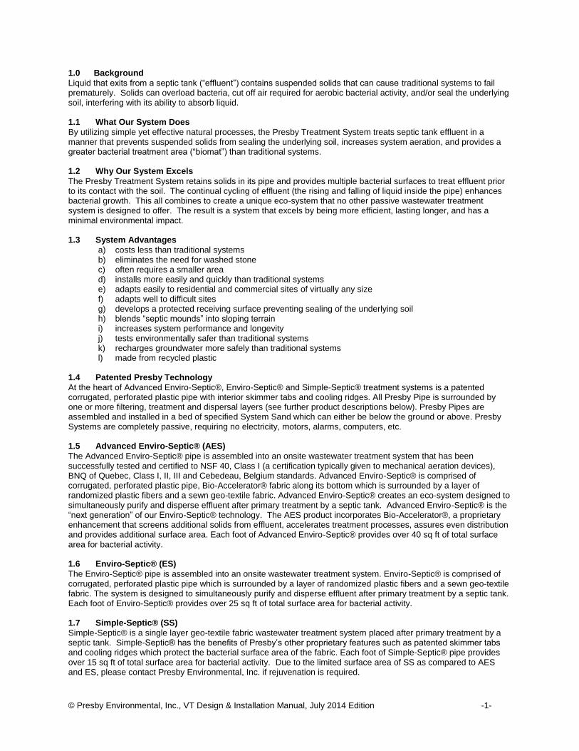
1.0 Background
Liquid that exits from a septic tank (“effluent”) contains suspended solids that can cause traditional systems to fail prematurely. Solids can overload bacteria, cut off air required for aerobic bacterial activity, and/or seal the underlying soil, interfering with its ability to absorb liquid. 1.1 What Our System Does
By utilizing simple yet effective natural processes, the Presby Treatment System treats septic tank effluent in a manner that prevents suspended solids from sealing the underlying soil, increases system aeration, and provides a greater bacterial treatment area (“biomat”) than traditional systems. 1.2 Why Our System Excels
The Presby Treatment System retains solids in its pipe and provides multiple bacterial surfaces to treat effluent prior to its contact with the soil. The continual cycling of effluent (the rising and falling of liquid inside the pipe) enhances bacterial growth. This all combines to create a unique eco-system that no other passive wastewater treatment system is designed to offer. The result is a system that excels by being more efficient, lasting longer, and has a minimal environmental impact. 1.3 System Advantages
a) costs less than traditional systems b) eliminates the need for washed stone c) often requires a smaller area d) installs more easily and quickly than traditional systems e) adapts easily to residential and commercial sites of virtually any size f) adapts well to difficult sites g) develops a protected receiving surface preventing sealing of the underlying soil h) blends “septic mounds” into sloping terrain i) increases system performance and longevity j) tests environmentally safer than traditional systems k) recharges groundwater more safely than traditional systems l) made from recycled plastic
1.4 Patented Presby Technology
At the heart of Advanced Enviro-Septic®, Enviro-Septic® and Simple-Septic® treatment systems is a patented corrugated, perforated plastic pipe with interior skimmer tabs and cooling ridges. All Presby Pipe is surrounded by one or more filtering, treatment and dispersal layers (see further product descriptions below). Presby Pipes are assembled and installed in a bed of specified System Sand which can either be below the ground or above. Presby Systems are completely passive, requiring no electricity, motors, alarms, computers, etc. 1.5 Advanced Enviro-Septic® (AES)
The Advanced Enviro-Septic® pipe is assembled into an onsite wastewater treatment system that has been successfully tested and certified to NSF 40, Class I (a certification typically given to mechanical aeration devices), BNQ of Quebec, Class I, II, III and Cebedeau, Belgium standards. Advanced Enviro-Septic® is comprised of corrugated, perforated plastic pipe, Bio-Accelerator® fabric along its bottom which is surrounded by a layer of randomized plastic fibers and a sewn geo-textile fabric. Advanced Enviro-Septic® creates an eco-system designed to simultaneously purify and disperse effluent after primary treatment by a septic tank. Advanced Enviro-Septic® is the “next generation” of our Enviro-Septic® technology. The AES product incorporates Bio-Accelerator®, a proprietary enhancement that screens additional solids from effluent, accelerates treatment processes, assures even distribution and provides additional surface area. Each foot of Advanced Enviro-Septic® provides over 40 sq ft of total surface area for bacterial activity. 1.6 Enviro-Septic® (ES)
The Enviro-Septic® pipe is assembled into an onsite wastewater treatment system. Enviro-Septic® is comprised of corrugated, perforated plastic pipe which is surrounded by a layer of randomized plastic fibers and a sewn geo-textile fabric. The system is designed to simultaneously purify and disperse effluent after primary treatment by a septic tank. Each foot of Enviro-Septic® provides over 25 sq ft of total surface area for bacterial activity. 1.7 Simple-Septic® (SS)
Simple-Septic® is a single layer geo-textile fabric wastewater treatment system placed after primary treatment by a septic tank. Simple-Septic® has the benefits of Presby’s other proprietary features such as patented skimmer tabs and cooling ridges which protect the bacterial surface area of the fabric. Each foot of Simple-Septic® pipe provides over 15 sq ft of total surface area for bacterial activity. Due to the limited surface area of SS as compared to AES and ES, please contact Presby Environmental, Inc. if rejuvenation is required.

© Presby Environmental, Inc., VT Design & Installation Manual, July 2014 Edition -2-
2.0 Ten Stages of Wastewater Treatment
The Presby Wastewater Treatment System's 10 STAGES OF TREATMENT
Advanced Enviro-Septic® (AES), Enviro-Septic® (ES) & Simple-Septic® (SS) Stage 1: Warm effluent enters the pipe and is cooled to ground temperature.
Stage 2: Suspended solids separate from the cooled liquid effluent.
Stage 3: Skimmers further capture grease and suspended solids from the existing effluent.
Stage 4: Pipe ridges allow the effluent to flow uninterrupted around the circumference of the pipe and aid in
cooling.
Stage 5: Bio-Accelerator® fabric screens additional solids from the effluent, enhances and accelerates treatment,
facilitates quick start-up after periods of non-use, provides additional surface area for bacterial growth, promotes even distribution, and further protects outer layers and the receiving surfaces so they remain permeable. (AES only)
Stage 6: A mat of coarse, randomly-oriented fibers separates more suspended solids from the effluent (AES & ES
only).
Stage 7: Effluent passes into the geo-textile fabrics and grows a protected bacterial surface.
Stage 8: Sand wicks liquid from the geo-textile fabrics and enables air to transfer to the bacterial surface.
Stage 9: The fabrics and fibers provide a large bacterial surface to break down solids.
Stage 10: An ample air supply and fluctuating liquid levels increase bacterial efficiency.
SKIMMER TABS
CROSS SECTION
SYSTEM SAND
1
2
3
5
4
6
7
8 9
10
2
EFFLUENT
SCUM
SLUDGE
BIO-ACCELERATOR
FABRIC (AES ONLY)
GEO-TEXTILE
FABRIC
COARSE
FIBERS
RIDGES
®
CIRBAF
ROTARELECCA-OI
B
AIR SPACE
®
(AES ONLY)
SEWN SEAM(ALWAY UP - AES ONLY)

© Presby Environmental, Inc., VT Design & Installation Manual, July 2014 Edition -3-
3.0 System Diagrams
Notes: Advanced Enviro-Septic® may be noted as “AES”, Enviro-Septic® as "ES" & Simple-Septic® as
“SS”. All in-ground systems must be level (see illustration in sect. 18.0, page 13).
SYSTEM SAND EXTENSION (WHEN REQUIRED)
OFFSET ADAPTER
COUPLINGS
SYSTEM SAND BED LENGTH
(ROW LENGTH + 2' MIN)
ROW LENGTH (100' MAX)
1' MIN TYP
PIPE LAYOUT WIDTH
SYSTEM SAND BED WIDTH
(PIPE LAYOUT WIDTH + 2' MIN)
10' PIPE
SEGMENT
PLAN VIEW
INLET
VENT ATTACHED TO
END OF LAST ROW
EXISTING GRADE
3 MIN
1SYSTEM SAND
SAND FILL
TYP
SYSTEM SAND EXTENSION TYP
(WHEN REQUIRED)
ALL PRESBY PIPE LAID LEVEL
WITHIN ±1/2"
1.5' FILL
EXTENSION(ALL SIDES)
4" MIN TOPSOIL 1' TYP ALL SIDES
12" MINIMUM OF SYSTEM SANDBELOW PRESBY PIPE
10%<EXISTING GRADE
3 MIN
1
SAND FILL
TYP
PIPE LAYOUT
WIDTH
12" MINIMUM OF SYSTEM
SAND BELOW PIPE6" MIN
1.5' CENTER-TO-CENTER
SPACING MIN TYP
SECTION VIEW
SECTION VIEW
SEPARATION TO S.H.W.T.,
LEDGE OR RESTRICTIVE
LAYER
SEPARATION TO
S.H.W.T., LEDGE OR
RESTRICTIVE LAYER
VENT 4"Ø MIN. ATTACHED TO END OF
LAST SERIAL LINE OR VENT MANIFOLD
INLET
RAISED
CONNECTION
3' M
IN
1' TYP
ALL SIDES
VENT TO 3' ABOVE
FINAL GRADE
SETBACKS FOR INGROUND
BEDS MEASURED TO SYSTEM
SAND. SEE VT RULES FOR
MOUND SYSTEM SETBACKS
RAISED CONNECTION
INLET
SYSTEM SAND EXTENSION
CROWN FINISH GRADE
SYSTEMS 10% SLOPES OR LESS
6" MINIMUM OF SYSTEM SAND
IF TOP OF PIPE IS BELOW GRADE
(SEE "IN-GROUND BEDS" SECTION)
SYSTEMS OVER 10% SLOPE
(ENTIRELY ABOVE GRADE)
12" MIN
3' MIN SYSTEM
SAND EXTENSION
1.5'
TYP
6" MIN
TYP
12" MIN
TYP
1.5' MIN TYP
1.5' TYP
ALL SIDES

© Presby Environmental, Inc., VT Design & Installation Manual, July 2014 Edition -4-
4.0 Presby System Components
4.1 Presby Pipe
a) Plastic pipe made with a significant percentage of recycled material b) 10 ft sections (can be cut to any length) c) Ridged and perforated, with skimmer tabs on interior d) AES only: Bio-Accelerator® along bottom of pipe (sewn seam is always placed up). e) AES & ES only: Surrounded by a mat of randomly-oriented plastic fibers f) Wrapped in a non-woven geo-textile fabric stitched in place g) Exterior diameter of 12 in. h) Each 10 ft section has a liquid holding capacity of approx. 58 gallons i) A 10 ft length of Presby Pipe is flexible enough to bend up to 90°
4.2 Offset Adapter
An offset adapter is a plastic fitting 12 in. in diameter with an inlet hole designed to accept a 4 inch sewer line, raised connection or vent pipe. The hole is to be installed in the 12 o’clock position. The distance from the bottom of the Offset Adapter to the bottom of its inlet hole is 7 in. When assembling pipes into rows, note that the geo-textile fabrics are placed over the edges of the Offset Adapter and Couplings. 4.3 Double Offset Adapter
A double offset adapter is a plastic fitting 12 in. in diameter with two 4 in. holes designed to accept a 4 in. inlet pipe, raised connection, vent or vent manifold, and/or bottom drain, depending upon the particular requirements of the design configuration. The 4 in. holes are to be aligned in the 12 o’clock and 6 o’clock positions. The holes are positioned 1 in. from the outside edge of the double offset adaptor and 2 in. from each other. 4.4 Coupling
A coupling is a plastic fitting used to create a connection between two pieces of Presby Pipe. Note that the couplings are wide enough to cover 1 or 2 pipe corrugations on each of the two pipe ends being joined. The couplings feature a snap-lock feature that requires no tools. When assembling pipes into rows, note that the geo-textile fabric does not go under couplings. Pull fabric back, install coupling, and then pull fabric over coupling. Also note, during installation in cold weather, couplings are easier to work with if stored in a heated location before use (such as a truck cab) before use. 4.5 Raised Connection
A raised connection is a PVC Sewer & Drain pipe configuration which is used to connect Presby Rows. Raised connections extend 2 in. to 4 in. into pipe and are installed on an angle (as shown below). All PVC joints should be glued. 5.0 Presby Environmental Standards
All Presby Systems must be designed and installed in compliance with the procedures and specifications described in this Manual and in the product’s Vermont approval. 6.0 Presby Pipe Sizing
Advanced Enviro-Septic®, Enviro-Septic® and Simple-Septic® all use the same bed sizing tables, pipe requirement and installation procedures noted in this manual. 7.0 Vermont Rules
This Manual is to be used in conjunction with the State of Vermont Wastewater Management Division’s Environmental Protection Rules, Chapter 1, Wastewater System and Potable Water Supply Rules, Effective September 29, 2007. Vermont linear loading requirements must always be honored for all perc rates.
SLOPING BED
2"-4"LEVEL
OFFSET
ADAPTER
4"DIA. RAISED CONNECTION BETWEEN ROWS
LEVEL BED

© Presby Environmental, Inc., VT Design & Installation Manual, July 2014 Edition -5-
7.1 Conflicts between Vermont Rules & Manual
In the event of contradictions between this Manual and Vermont Department of Environmental Conservation regulations, Presby Environmental, Inc. should be contacted for technical assistance (800-473-5298). Exceptions to any Vermont rules other than those specifically discussed in this Manual require a DEC waiver. Please contact us for technical assistance at (800) 473-5298. 8.0 Certification Requirements
Any designers and installers who have not previously attended a Presby Environmental, Inc. “Certification Course” are required to obtain Presby Certification. Certification is obtained by attending a Certification Course presented by Presby Environmental, Inc. or its sanctioned representative. Certification can also be obtained by viewing tutorial videos on our website (high speed connection required) and then successfully passing a short assessment test, which is also available over the internet. All professionals involved in the inspection, review or certification of Presby Systems should also become Presby Certified. For questions about our products or the information contained in this Manual, or to register for a Certification Course, please contact us at 1-800-473-5298. 9.0 Table A: Presby Pipe Required
Table A: Presby Pipe Required Perc Rate
MPI Number of Bedrooms *Commercial
per 100 GPD
2 3 4 5 6 Add'l Room
1 - 4 85 123 165 207 249 42 47 5 - 6 90 135 180 225 270 45 50 7 - 9 100 150 200 250 300 50 55
10 - 13 110 165 220 275 330 55 60 14 - 19 120 180 240 300 360 60 66 20 - 30 130 195 260 325 390 65 71 31 - 120 140 210 280 350 420 70 77
Feet of Pipe Required Minimum * For high strength effluent contact Presby Environmental for recommendations
10.0 Table B: System Sand Bed Area & Allowable System Slope
Perc Rate MPI
Bedrooms Comm. per 100 GPD M
ax
Perc Rate MPI
Bedrooms Comm. per 100 GPD M
ax
2 3 4 Add'l 2 3 4 Add'l
1-2 117 175 205 30 42
20%
Syste
m S
lop
e
61 - 62 460 689 804 115 165
15%
3-4 117 175 205 30 42 63 - 64 467 700 817 117 167 5 - 6 143 215 251 36 52 65 - 66 474 711 830 119 170 7 - 8 165 248 289 42 59 67 - 68 482 722 842 121 172 9 - 10 185 277 323 47 66 69 - 70 489 733 855 123 175
11 - 12 203 304 354 51 73 71 - 72 495 743 867 124 177
10%
Syste
m S
lop
e
13 - 14 219 328 382 55 78 73 - 74 502 753 879 126 180 15 - 16 234 350 409 59 84 75 - 76 509 763 890 128 182 17 - 18 248 372 434 62 89 77 - 78 516 773 902 129 184 19 - 20 261 392 457 66 94 79 - 80 522 783 914 131 187 21 - 22 274 411 479 69 98 81 - 82 529 793 925 133 189 23 - 24 286 429 501 72 103 83 - 84 535 802 936 134 191 25 - 26 298 447 521 75 107 85 - 86 541 812 947 136 194 27 - 28 309 464 541 78 111 87 - 88 548 821 958 137 196 29 - 30 320 480 560 80 115 89 - 90 554 831 969 139 198 31 - 32 330 495 578 83 118 91 - 92 560 840 980 140 200
0%
Syste
m S
lop
e
33 - 34 341 511 596 86 122 93 - 94 566 849 990 142 202 35 - 36 350 525 613 88 125 95 - 96 572 858 1,001 143 205 37 - 38 360 540 630 90 129 97 - 98 578 867 1,011 145 207 39 - 40 369 554 646 93 132 99 - 100 584 875 1,021 146 209 41 - 42 379 568 662 95 136 101 - 102 590 884 1,031 148 211 43 - 44 387 581 678 97 139 103 - 104 595 893 1,042 149 213 45 - 46 396 594 693 99 142 105 - 106 601 901 1,052 151 215 47 - 48 405 607 708 102 145 107 - 108 607 910 1,061 152 217 49 - 50 413 619 722 104 148 109 - 110 612 918 1,071 153 219 51 - 52 421 631 737 106 151 111 - 112 618 927 1,081 155 221 53 -54 429 643 751 108 154 113 - 114 623 935 1,090 156 223 55 - 56 437 655 764 110 156 115 - 116 629 943 1,100 158 225 57 - 58 445 667 778 112 159 117 - 118 634 951 1,109 159 227 59 - 60 452 678 791 113 162 119 - 120 640 959 1,119 160 229
Square Feet of System Sand Minimum Square Feet of System Sand Minimum
Table B already reflects the 50% maximum allowed reduction in bed area. This table is based on a daily design flow of 140 GPD for each of the first three bedrooms and 70 GPD thereafter.

© Presby Environmental, Inc., VT Design & Installation Manual, July 2014 Edition -6-
11.0 Table C: Row Length and Pipe Layout Width
Total Linear Feet of Presby Pipe
Ro
w L
en
gth
(ft
)
30 60 90 120 150 180 210 240 270 300 330 360 390 420 450
35 70 105 140 175 210 245 280 315 350 385 420 455 490 525
40 80 120 160 200 240 280 320 360 400 440 480 520 560 600
45 90 135 180 225 270 315 360 405 450 495 540 585 630 675
50 100 150 200 250 300 350 400 450 500 550 600 650 700 750
55 110 165 220 275 330 385 440 495 550 605 660 715 770 825
60 120 180 240 300 360 420 480 540 600 660 720 780 840 900
65 130 190 260 325 390 455 520 585 650 715 780 845 910 975
70 140 210 280 350 420 490 560 630 700 770 840 910 980 1,050
75 150 225 300 375 450 525 600 675 750 825 900 975 1,050 1,125
80 160 240 320 400 480 560 640 720 800 880 960 1,040 1,120 1,200
85 170 255 340 425 510 595 680 765 850 935 1,020 1,105 1,190 1,275
90 180 270 360 450 540 630 720 810 900 990 1,080 1,170 1,260 1,350
95 190 285 380 475 570 665 760 855 950 1,045 1,140 1,235 1,330 1,425
100 200 300 400 500 600 700 800 900 1,000 1,100 1,200 1,300 1,400 1,500
# of Rows 2 3 4 5 6 7 8 9 10 11 12 13 14 15
1.50' 2.50 4.00 5.50 7.00 8.50 10.00 11.50 13.00 14.50 16.00 17.50 19.00 20.50 22.00
Pipe Layout Width at 1.5(ft) Center-to-Center row spacing (outermost width of rows) Ex: select a row length and move right until the minimum amount of pipe is found (more is allowed). Then move down to find the
number of rows required; continue downward in the same column to find the pipe layout width for your spacing.
12.0 General Design Criteria
The material described in this section applies to all percolation rates unless otherwise specified. 12.1 Alarms & Baffles
a) All pump systems to have a high water alarm float or sensor installed inside the pump chamber.
b) All septic tanks must be equipped with baffles to prevent excess solids from entering the Presby System.
12.2 Barrier Materials over System Sand
No barrier materials (hay, straw, tarps, etc.) are to be placed between the System Sand and cover material; such materials may cut off necessary oxygen supply to the system. 12.3 Daily Design Flow
Residential daily design flow for Presby Systems is calculated in accordance with Vermont rules. Systems servicing more than two residences shall use the Commercial portions of all Tables. The minimum daily design flow for any single-family residential system on its own lot is two bedrooms and 300 GPD for any commercial system.
a) Certain fixtures, such as jetted tubs, may require an increase in the size of the septic tank. b) Daily design flow for a single bedroom apartment with a kitchen connected to a residence (also
sometimes referred to as a “studio” or “in-law apartment”) shall be calculated by adding two additional bedrooms (280 GPD).
c) When daily design flow is determined by water meter use for commercial systems, refer to Vermont Rules, Section 1-808.
d) PEI recommends taking the average daily flow from a peak month and multiplying it by a peaking factor of 2 to 3 times.
e) Note that “daily design flows” are calculated to assume occasional “peak” usage and a factor of safety; Systems are not expected to receive continuous dosing at full daily design load.
12.4 Distribution Box (D-box)
A device used to divide effluent flow to the field(s) or provide velocity reduction of incoming effluent to reduce turbulence. A D-box is required when using Combination distribution (see sect. 15.0, page 11) or when pumping effluent to the field (see sect. 24.0, page 17). Basic Serial systems (see sect. 13.0, page 10) gravity feeding to a field do not require a D-box. All used D-box outlets, except outlets used for venting, must have flow equalizers. 12.5 Distribution Box Manifold
A manifolded D-box is utilized to evenly divide daily flows to multiple beds. Several D-box outlets are joined by means of a manifold, which helps to compensate for uneven distribution. All used outlets must have a flow equalizer. If a distribution box manifold is utilized to divide large flows, velocity reduction of the incoming effluent is necessary

© Presby Environmental, Inc., VT Design & Installation Manual, July 2014 Edition -7-
TYP
3 MIN
1
1.5' FILL EXTENSION
(ALL SIDES)4" MIN TOPSOIL
1
3 MIN
TYP
6" MIN
1.5' FILL EXTENSION
(ALL SIDES)
12" MIN
6" MIN TYP
12" MIN
TYP SAND
FILL SAND
FILL
4" MIN TOPSOIL
SYSTEM SAND EXTENSION
(3' MIN IF SYSTEM SLOPE >10%)
6" IN-GROUND SYSTEMS
12" MOUND SYSTEMS
12" MIN
12
"
6"
12
"
6"
Illustration of Manifolded D-box: 12.6 Effluent Filters
a) Effluent Filters are required in Vermont. b) Effluent filters must be maintained on at least an annual basis. Follow manufacturer’s instructions
regarding required inspections, cleaning and maintenance of the effluent filter. c) Effluent Filters must allow the free passage of air to ensure the proper functioning of the system. A
blocked filter in any on-site septic system could interfere with venting, causing the system to convert to an anaerobic state and result in a shortened life.
d) Charcoal filters in vent stacks (for odor control) are not recommended by PEI. They can block air flow and potentially shorten system life. Contact PEI for recommendations to correct odor problems.
12.7 End-to-End Preferred Over Side-to-Side
If site conditions permit, End-to-End multiple bed configurations are preferable to Side-to-Side configurations (see sect. 17.0, page 12). 12.8 Fill Extensions for Raised (Mound) Systems
If any portion of the bed extends above the original grade the fill covering the field cannot begin the 3:1 side slope taper for a distance of 1.5 ft minimum from the outmost edge of any Presby Pipe. If the bed has System Sand Extension(s), the side slope taper must allow at least 12 in. of cover over the outmost edge of the extension.
a) Tapering is to be 3 horizontal feet minimum for each 1 foot of vertical drop. b) Refer to Site Preparation Prior to Excavation, sect. 27.9, page 22 for erosion control and surface water
diversion procedures. Level Bed: Sloping Bed: 12.9 Flow Equalizers Required
All distribution boxes used to divide effluent flow require flow equalizers in their outlets. Flow equalizers are limited to a maximum of 20 GPM per equalizer (10 GPM is recommended). 12.10 Garbage Disposals (a.k.a. Garbage Grinders)
No additional Presby Pipe is required when using a garbage disposal (grinder). If a garbage disposal is utilized, follow the State’s requirements regarding septic tank sizing. Multiple compartment septic tanks or multiple tanks are preferred and should be pumped as needed. 12.11 Percolation Rates 61-120 MPI Additional Criteria
a) System must be designed as an Elevated Bed (mound). b) Non-Conventional Systems cannot be used. c) Multiple beds are common in these soils. d) Separate multiple beds in accordance with Vermont rules. e) Systems should be designed as long and narrow as the site allows. f) A minimum of 12 in. of System Sand required below all Presby Pipes.
12.12 Presby Pipe Substitutions
Due to superior characteristics, it is acceptable to substitute AES for specified ES or SS pipe; or to substitute ES for specified SS pipe for permitted wastewater designs. All other substitutions to the Presby pipe shown on the approved septic system design are not allowed without the written approval of the system’s designer and a Wastewater System and Potable Water Supply Permit amendment. This includes substituting another manufacturer’s pipe or even another less superior model of Presby Pipe.
INLET
OUTLET
D-BOX
OUTLET
UNUSED
OUTLET
4" Ø PVC
TYPICAL
DISTRIBUTION BOX MANIFOLD(TO EVENLY DIVIDE FLOW)
NOTE: UTILIZING EVERY OTHER
OUTLET WILL PROVIDE ROOM FOR
REQUIRED PIPING AND ALLOW
FOR EASIER INSTALLATION
© Presby Environmental, Inc., VT Design & Installation Manual, July 2014 Edition -8-
12.13 Pressure Distribution The use of pressure distribution lines in Presby Systems is prohibited. Pumps may be utilized when necessary only
to gain elevation and to feed a distribution box which then distributes effluent by gravity to the Presby Field. 12.14 Replacement Field for Mound Systems
In the event of system malfunction, contact PEI for technical assistance prior to attempting Rejuvenation procedures. Refer to System Bacteria Rejuvenation and Expansion, sect. 28.0, page 23. In the unlikely event that a Presby System needs to be replaced:
a) An Elevated System can be reinstalled in the same location, eliminating the need for a replacement field reserve area if allowed by state and local authorities.
b) All unsuitable material must be removed prior to replacement system construction. c) Disposal of hazardous materials to be in accordance with state and local requirements. d) Contact the appropriate local or state department for necessary permits.
12.15 Replacement Field for In-Ground Systems
In-Ground systems must be replaced in accordance with Vermont rules and may require the replacement system to be located in the reserve area. 12.16 Row Requirements
a) Maximum row length for any system is 100 ft. b) Minimum row length is 30 ft (For acceptable exceptions to this rule, refer to Non-Conventional System
Configurations, sect. 22.0, page 15.) c) Row Center-to-Center Spacing is 1.5 ft min. for all perc rates. Row spacing may be increased if desired. d) For Sloping Beds: the elevations must be provided on the construction drawing for each Presby Pipe row
in the sloping bed system. e) All rows must be laid level to within +/- ½ in. (total of 1 in.) of the specified elevation and preferably should
be parallel to the contour of the site. f) It is easier if row lengths are designed in exact 10 ft increments since Presby Pipe comes in 10 ft sections.
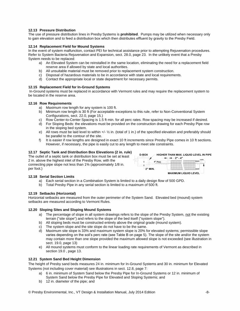
However, if necessary, the pipe is easily cut to any length to meet site constraints. 12.17 Septic Tank and Distribution Box Elevations (2 in. rule)
The outlet of a septic tank or distribution box must be set at least 2 in. above the highest inlet of the Presby Row, with the connecting pipe slope not less than 1% (approximately 1/8 in. per foot.) 12.18 Serial Section Limits
a) Each serial section in a Combination System is limited to a daily design flow of 500 GPD. b) Total Presby Pipe in any serial section is limited to a maximum of 500 ft.
12.19 Setbacks (Horizontal)
Horizontal setbacks are measured from the outer perimeter of the System Sand. Elevated bed (mound) system setbacks are measured according to Vermont Rules. 12.20 Sloping Sites and Sloping Mound Systems
a) The percentage of slope in all system drawings refers to the slope of the Presby System, not the existing terrain ("site slope") and refers to the slope of the bed itself ("system slope").
b) All sloping beds must be constructed entirely above the original grade (mound system). c) The system slope and the site slope do not have to be the same. d) Maximum site slope is 33% and maximum system slope is 20% for elevated systems; permissible slope
varies depending on the soil’s perc rate (see Table B on page 5). The slope of the site and/or the system may contain more than one slope provided the maximum allowed slope is not exceeded (see illustration in sect. 19.0, page 13)
e) All mound systems must conform to the linear loading rate requirements of Vermont as described in section 19.0 , page 13.
12.21 System Sand Bed Height Dimension
The height of Presby sand beds measures 24 in. minimum for In-Ground Systems and 30 in. minimum for Elevated
Systems (not including cover material) see illustrations in sect. 12.8, page 7:
a) 6 in. minimum of System Sand below the Presby Pipe for In-Ground Systems or 12 in. minimum of System Sand below the Presby Pipe for Elevated and Sloping Systems; and
b) 12 in. diameter of the pipe; and
4" PVC
2" MIN.
D-BOX
LEVEL
MAXIMUM LIQUID LEVEL
HIGHER THAN MAX. LIQUID LEVEL IN PIPE
2" - 4"

© Presby Environmental, Inc., VT Design & Installation Manual, July 2014 Edition -9-
c) 6 in. minimum of System Sand above the Presby Pipe. d) The System Sand Extension area (any part of the System Sand bed that is more than 1 ft away from the
Presby Pipe) is required to be a minimum of 6 in. deep. 12.22 System Sand Extensions
In Systems sloping more than 10%, a System Sand extension is required. The System Sand Extension area is additional System Sand added to the down slope side of all systems sloping more than 10%. The System Sand extension area is a minimum of 6 in. deep and extends a minimum of 3 ft beyond the tall portion of the System Sand bed on the down slope edge of the bed (see illustration of System Sand Extension in sect. 12.8, page 7). For multiple slope beds, if any portion of the bed has a system slope greater than 10% a system sand extension is required.
12.23 System Sand Requirements for All Beds It is critical to the proper functioning of the Presby System that the proper amount and type of System Sand be
installed. System Sand must be clean, granular sand free of organic matter and must adhere to Vermont §1-913(c),(2) fill material, except: A maximum of 3% of total sand may pass through a #200 sieve (verified by washing sample per requirements of ASTM C-117). ASTM C-33 (“concrete sand”) is acceptable for use as System Sand providing that no more than 3% can pass a #200 sieve (verified by washing sample per requirements of ASTM C-117 as noted in the ASTM C-33 specification). System Sand is placed a minimum of 6 in. below the Presby Rows for below grade systems, a minimum of 12 in. below the Presby Rows for mound/elevated/sloping systems, a minimum of 6 in. above the Presby Rows, and a minimum of 12 in. horizontally around the perimeter of the rows. Note: System Sand may be used in place of sand fill. 12.24 Sand Fill
Sand fill is used to raise the elevation of the system in order to meet the required separation distance from the SHWT or other restrictive feature. Sand fill is defined by Vermont §1-913(c). No organic material is allowed. If §1-913(c)(2) or §1-913(c)(3) material is used, no more than 5% shall pass a #200 sieve (tested per ASTM C-117) and no stones over 3/4 inch is size. 12.25 System Side Slopes (Side Slope Tapers)
Side slope tapering is to be a maximum of 3:1; steeper side slope tapering requires a state waiver. There must always be a minimum of 12 in. of cover over the ends of any System Sand Extension (see illustration in sect. 12.8, page 7). 12.26 Topsoil (a.k.a. “Loam”)
Suitable earth cover, similar to the naturally occurring soil at the site and capable of sustaining plant growth, is required as the uppermost layer over the entire system (including fill extensions, side slope extensions and System Sand extensions). The topsoil layer should be a minimum of 4 in. deep and should be immediately seeded or mulched in order to prevent erosion. 12.27 Topographic Position Requirement
The system location must be located in an area that does not concentrate water, both surface and subsurface. If allowed by state and local authorities, altering the terrain upslope of a system may alleviate this requirement if the waters are sufficiently altered to redirect flows away from the field. 12.28 Venting Requirements
Venting is required for all Presby Systems (see Venting Requirements, sect. 25.0, page 18). 12.29 Velocity Reduction
Reduce the velocity of liquid entering Presby Pipe. A distribution box with a baffle or inlet tee may be adequate for velocity reduction in most systems. When pumping to gain elevation, pump to an oversized distribution box or equivalent with proper baffles or tee at the end of the delivery line. 12.30 Vertical Separation Distances
Required minimum vertical separation distance to seasonal high water table (SHWT) is 36 in. and 48 in. to ledge/bedrock. Vertical separation distances are measured from the bottom of the Presby Pipe (see illustration in sect. 3.0, page 3). 12.31 Wastewater Strength
Presby Systems are approved for use when treating low and moderate strength wastewater as defined by our approval and the Vermont rules. Systems to treat high strength wastewater may be approved on a case by case basis. Please contact Presby Environmental for design recommendations.

© Presby Environmental, Inc., VT Design & Installation Manual, July 2014 Edition -10-
ROW 1
ROW 2
ROW 3
ROW 4
(12" MOUND)
(6" IN-GROUND)
6" MIN.
LE
VE
L B
ED
SE
CT
ION
VIE
W
ROW 1
ROW 2
ROW 3
ROW 4
12" MIN
SL
OP
ING
BE
D S
EC
TIO
N V
IEW
SL
OP
E
6" TYPD-BOX AT HIGH SIDE OF BED
LEVEL BED SLOPING BED
SYS SAND EXTENSION
DOWNHILL SIDE ONLY
SYS SAND
EXTENSION
SYS SAND
EXTENSION
6" MIN
6"
3' MIN
VE
NT
INL
ET
100' MAX
VE
NT
INL
ET
12.32 Water Purification Systems a) Water purification systems and water softeners should not discharge into any Presby System. This
“backwash” does not require treatment and the additional flow may overload the system. b) Consult with your designer for alternative means of dispersal. c) If there is no alternative means of disposing of this backwash other than in the Presby System, then the
system will need to be “oversized.” Calculate the total amount of backwash in GPD, multiply by 3, and add this amount to the daily design flow when determining the field and septic tank sizing.
d) Water purification systems and water softeners require regular routine maintenance; consult and follow the manufacturer’s maintenance recommendations.
12.33 Long, Narrow Systems Recommended Perc Rates 61-120 MPI
All Presby Systems in soils with perc rates 61-120 MPI are recommended to be designed and installed as long and narrow as possible for the site. Long, narrow configurations provide the optimal liquid distribution conditions. Vermont linear loading rates must always be honored. Example of a long and narrow system using two rows:
13.0 Basic Serial Distribution
Presby Rows are connected in series at the ends with raised connections, using offset adapters. Basic Serial distribution systems are quick to develop a strong biomat in the first row, provide a longer flow route, improved effluent treatment and ensure air will pass through all the Presby Rows. Other criteria:
a) May be used for single beds of 900 GPD or less. b) Basic Serial distribution incorporates rows in serial distribution in a single bed. c) Does not require the use of a D-box unless utilizing a pump. d) A maximum of 500 ft of Presby Pipe per Basic Serial bed. This may force the use of Combination
Distribution in higher perc rates. e) When a D-box is being used, a flow equalizer is not required because effluent flow is not being divided. f) For sloping beds, the System Sand Extension is placed entirely on the downhill side and must be at least 3
ft (4 ft when measured from the pipe). g) System Sand Extensions (if required) is divided symmetrically for level beds (as shown). h) System Sand Extension (if required) is placed entirely on downhill side of a sloping bed (as shown). i) Illustration of Level and Sloping Basic Serial Systems:
14.0 D-Box (Parallel) Distribution
a) All rows in this configuration must be the same length and never longer than 100 ft. b) Flow equalizers must be used in the D-Box outlets feeding the Presby rows. c) Use a Vent Manifold to connect the ends of all rows to ensure adequate air flow. Manifold to be sloped
toward Presby Pipes (like the Raised Connection). d) Place the D-box on level, firmly compacted soil. e) A 2 in. min. drop is required between the D-box outlets and the Presby Pipe inlets. f) System Sand Extensions (if required) divided symmetrically for level beds (as shown). g) System Sand Extension (if required) placed entirely on downhill side of bed (as shown).
INLET
SE
CT
ION
VIE
W
12"
6"
3'
SYSTEM SAND EXTENSION
ENTIRELY DOWNHILL SIDE
SL
OP
E
12"
6"
Row #1 Row #2VENT TYP.
INLET
SY
ST
EM
SA
ND
BE
D W
IDT
H
SE
CT
ION
VIE
W
SYSTEM SAND BED LENGTH
6" (IN-GROUND)
12" (MOUND)
6" TYP.100'
MAX. TYP. 12" MIN. TYP.
3'
SYSTEM SAND
EXTENSION 12"
6"
Row #1 Row #2
12" SYSTEM SAND MIN.
D-BOX
D-BOX
LEVEL BED SLOPING BED

© Presby Environmental, Inc., VT Design & Installation Manual, July 2014 Edition -11-
INL
ET
ROW 1
ROW 2
ROW 3
ROW 4
VENT STACK
(12" MOUND)
(6" IN-GROUND)
6" MIN.
LE
VE
L B
ED
SE
CT
ION
VIE
W
ROW 1
ROW 2
ROW 3
ROW 4
12" MIN
SL
OP
ING
BE
D S
EC
TIO
N V
IEW
SL
OP
E
6" TYPD-BOX AT HIGH SIDE OF BED
LEVEL BED SLOPING BED
SYS SAND EXTENSION
DOWNHILL SIDE ONLY
SYS SAND
EXTENSION
SYS SAND
EXTENSION
6" MIN
6"
3' MIN
INL
ET
VENT STACK
h) Illustrations for D-Box (Parallel) Distribution:
15.0 Combination Serial Distribution
Combination Serial distribution within one bed, or multiple beds, is required for systems with daily design flows greater than 900 GPD. Combination Serial distribution is quick to develop a strong biomat in the first row of each section, providing improved effluent treatment. Each Combination Serial section is limited to a maximum loading of 500 gallons/day and a maximum of 500 ft of Presby Pipe.
a) Combination Serial distribution consists of two or more serial sections installed in a single bed. b) Each section in a Combination Serial system consists of a series of Presby Rows connected at the ends
with raised connections, using offset adapters and PVC sewer and drain pipe. c) Maximum length of any row is 100 ft. d) Maximum 500 ft Presby Pipe in any serial section. e) Serial Section loading limit is 500 GPD. f) There is no limit on the number of Combination Serial Sections within a bed. g) System Sand Extensions (if required) divided symmetrically for level beds (as shown). h) System Sand Extension (if required) placed entirely on downhill side of bed (as shown). i) When the vent manifold is on the same side as the serial section inlets, the manifold runs over the top of
these inlets (as shown).
j) Illustrations of Combination Serial Systems:
15.1 Section Loading
Each section in a Combination Serial system has a maximum daily design flow of 500 GPD. More than the minimum number of sections may be used. Ex: Daily design flow = 1,000 GPD requires (1,000 ÷ 500) = 2 sections min.
15.2 Section Length Requirement
a) Each section must have the same minimum linear feet of pipe. b) The minimum linear feet of pipe per section is determined by dividing the total linear feet required in the
Presby System by the number of sections required. c) A section may exceed the minimum linear length. d) Rows within a section may vary in length to accommodate site constraints (See Non-Conventional
Configurations, sect. 22.0, page 15).
16.0 Butterfly Configuration
A Butterfly Configuration system is considered a single bed system and therefore separation distance between the left and right halves of the system is a minimum of 2 ft.
INL
ET
ROW 1
ROW 2
ROW 3
ROW 4
VENT STACK
D-BOX IN CENTER OF BED
MANIFOLD ENDS OF ALL ROWS (12" MOUND)
(6" IN-GROUND)
6" MIN.
LE
VE
L B
ED
SE
CT
ION
VIE
W
INL
ET
ROW 1
ROW 2
ROW 3
ROW 4
12" MIN
SL
OP
ING
BE
D S
EC
TIO
N V
IEW
SL
OP
E
6" TYP
D-BOX AT HIGH SIDE OF BED
LEVEL BED SLOPING BED
SYS SAND EXTENSION
DOWNHILL SIDE ONLY
SYS SAND
EXTENSION
SYS SAND
EXTENSION
6" MIN
6"
3' MIN

© Presby Environmental, Inc., VT Design & Installation Manual, July 2014 Edition -12-
a) A “butterfly configuration,” such as the one shown below, is considered a single bed system with two or more sections (can also be D-Box or Combination configurations).
b) A minimum 2 ft separation distance (measured pipe to pipe) is required between the left and right sides provided that the elevation of the two sides is the same or within 1 ft of the same elevation. In the event of an elevation differential greater than 1 ft, the two sides would be considered separate beds.
c) Maximum length of any row is 100 ft. d) Serial Section loading limit is 500 GPD. e) Serial Sections are limited to a maximum of 500 ft of Presby Pipe. f) Beds can contain any number of serial sections. g) System Sand Extensions (if required) divided symmetrically for level beds. h) System Sand Extension (if required) placed entirely on downhill side of bed. i) The configuration shown below can accept up to 1,000 GPD (2 sections x 500 GPD/section = 1,000 GPD)
Illustration of a Butterfly configuration: Level Bed (System Sand Extension symmetrical) Sloping Bed (System Sand Extension down slope only)
17.0 Multiple Bed Distribution
Multiple Bed distribution incorporates two or more beds, each bed with Basic Serial, Combination Serial, or D-Box distribution, and each receiving an equal amount of effluent from a D-Box. Multiple beds may be oriented along the contour of the site or along the slope of the site.
a) Each bed must have the same minimum linear feet of pipe. The minimum linear feet of pipe per bed is determined by dividing the total linear feet required in the Presby System by the number of beds.
b) Rows within a bed may vary in length to accommodate site constraints, except with D-Box configuration which requires all rows to be the same length.
c) End-to-End configurations are preferred to Side-to-Side configurations. d) In Side-to-Side configuration one bed is placed beside another or one bed is place down slope of another.
Vermont linear loading must be considered when choosing this multiple bed layout.
e) Illustration of End-to-End Multiple Beds:
f) Illustration of Side -to-Side Multiple Beds:
17.1 Bed Separation Distances
A 10 ft separation distance is required by the State of Vermont between multiple beds. a) For in-ground systems, this distance is measured from the closest edges of the System Sand beds. b) For mound systems, the 10 ft separation distance is measured from toe-of-slope of one bed to nearest
toe-of-slope of other bed(s). To accommodate construction access and site constraints, additional separation distance may be necessary.
ROW 1
ROW 2
ROW 3
ROW 4
ROW 5
ROW 6
SECTION #1 SECTION #2
VENT TYP.
ROW 1
ROW 2
ROW 3
ROW 4
ROW 5
ROW 6
SECTION #1 SECTION #2
VENT TYP.
LE
VE
L B
ED
SE
CT
ION
VIE
W
SL
OP
ING
BE
D S
EC
TIO
N V
IEW
SL
OP
E
OFFSET ADAPTER
COUPLINGS
ROW 1
ROW 2
ROW 3
RAISED
CONNECTION
12" SYSTEM SAND MIN. INL
ET D-BOX WITH FLOW
EQUALIZERS
ROW 4
ROW 5
ROW 6
VENT TYP.

© Presby Environmental, Inc., VT Design & Installation Manual, July 2014 Edition -13-
6" MIN
12"
6" MIN
4" MIN
SYSTEM SAND
AES OR ES PIPEORIGINAL GRADE
SYSTEM SAND
1'1' PIPE BED WIDTH
SYSTEM SAND BED WIDTH
REQUIRED
OFFSET
VENT 3' ABOVE
FINAL GRADE
17.2 Total Linear Feet Requirement
a) Each section or bed must have at least the minimum linear feet of pipe (total feet of pipe required divided by number of sections equals the minimum number of feet required for each section or bed).
b) A section or bed may exceed the minimum linear length. c) Rows within a section or bed may vary in length to accommodate site constraints. d) Total Presby Pipe in any serial section is limited to a maximum of 500 ft.
18.0 In-Ground Bed Systems
Presby Systems are installed below existing grade for sites with no soil restrictive features to limit placement. a) Limited to soils with a perc rate of 1-60 MPI b) All In-Ground Systems must be installed level. c) The top of all Presby Pipes must be located below original grade (see illustration in sect. 17.2, page 13) d) Only 6 in. of System Sand are required below the Presby Pipes. e) In-ground on level site:
f) In-ground on sloping site: 19.0 Elevated Bed Systems (Mounds)
Elevated Presby Beds are designed for sites with soil, depth to groundwater or restrictive feature constraints that do not allow for In-Ground Bed Systems. An Elevated bed system is a soil absorption field with any part of the Presby Pipes above original grade. Elevated System Requirements:
a) All systems in soils with perc rates 61-120 MPI must be constructed as Elevated Bed (“mound”) systems.
b) Elevated systems may be installed level or sloping and must be vented.
c) Elevated Systems require 12 in. of System Sand below the Presby Pipes.
d) For System Sand beds wider than 10 ft the linear loading rate must meet the following requirements:
1) The linear loading rate is no more than 10 gallons per linear foot per day when the site limitations allow for a prescriptive mound design; or
2) The linear loading rate is more than 10 gallons per day per linear foot but is supported by a hydrogeologic analysis and the elevation of the Presby Piping will comply with the required minimum vertical separation above the induced ground water mounding.
3) Sites not meeting the requirements for a prescriptive mound will be evaluated using the performance-based design approach, and may, if supported by the hydrogeologic analysis, use linear loading rates exceeding 10 gallons per day per linear foot provided the elevation of the Presby Piping will comply with the required minimum vertical separation above the induced ground water mounding.
4) The linear loading rate is based on the length of the row length plus a maximum of two ft of System Sand at the ends of the row.
SYSTEM SAND
6" SYSTEM SAND
CROWN OF PIPE BELOW
ORIGINAL GRADE
ORIGINAL GRADE
TYP 13
ORIGINAL GRADE

© Presby Environmental, Inc., VT Design & Installation Manual, July 2014 Edition -14-
EXISTING GRADE LESS THAN 10%
3
1
SYSTEM SAND
TYP
EXISTING GRADE OVER 10%
6" MIN
TRANSITION LAYER
12" MIN
EXISTING GRADE
3 MIN
1SYSTEM SAND
SAND FILL
TYP
SYSTEM SAND EXTENSION TYP
(WHEN REQUIRED)
ALL PRESBY PIPE LAID LEVEL
WITHIN ±1/2"
1.5' FILL
EXTENSION(ALL SIDES)
4" MIN TOPSOIL 1' TYP ALL SIDES
12" MINIMUM OF SYSTEM SANDBELOW PRESBY PIPE
SECTION VIEW
SEPARATION TO S.H.W.T.,
LEDGE OR RESTRICTIVE
LAYER
VENT 4"Ø MIN. ATTACHED TO END OF
LAST SERIAL LINE OR VENT MANIFOLD
INLET
3' M
IN CROWN FINISH GRADE
SYSTEMS 10% SLOPES OR LESS
6" MINIMUM OF SYSTEM SAND
IF TOP OF PIPE IS BELOW GRADE
(SEE "IN-GROUND BEDS" SECTION)
6" MIN
TYP
12" MIN
TYP
1.5' MIN TYP
Level elevated bed: Beds with multiple slopes: 20.0 Angled Beds
Angled configurations generally have one or more specific bends, but the rows should follow the contour of the site as much as possible. Rows are angled by bending pipes (first drawing, below) or by using offset adapters (second drawing, below). A 10 ft length of Presby Pipe may be bent up to 90°. The angled system shown to the right requires 30 ft minimum row lengths. Illustrations of Angled Beds:
21.0 Curved Beds
Curved configurations work well around structures, setbacks, and slopes. Multiple curves can be used within a system to accommodate various contours of the site.
INLET
VENT
EX I ST I NG DR I VEWAY
YAWEVIRDGNITSIXE
6' RA
DIU
S
MIN
INLET
VENT
BUILDING OR
OBSTACLE
12" MIN OF SYSTEM SAND
AROUND PERIMETER OF PIPES
SYSTEMSAND
EX
TE
NS
ION
3' MIN SYSTEM
SAND EXTENSION
REQUIRED FOR
SLOPES OVER 10%
30' MINIMUM LINE
LENGTH
SLOPE
INLET
BUILDING OR
OBSTACLE
SYSTEM SAND
EX
TE
NS
ION
VENT12" MIN OF SYSTEM SAND
AROUND PERIMETER OF PIPES
3' MIN SYSTEM
SAND EXTENSION
REQUIRED FOR
SLOPES OVER 10%
30' MINIMUM
LINE LENGTH
RIGHT ANGLE RAISED
CONNECTION TYP.

© Presby Environmental, Inc., VT Design & Installation Manual, July 2014 Edition -15-
75' ROW LENGTH SECTION #1 (ROWS 1 & 2)
50' ROW LENGTH SECTION #2 (ROWS 3 - 5)
30' ROW LENGTH
SECTION #3 (ROWS 6 - 10)
SETBACK
RESTRICTION
INLET
22.0 Non-Conventional System Configurations 1-60 MPI Only
Non-conventional system configurations may have irregular shapes to accommodate site constraints and are limited to soils with a percolation rate of 1-60 MPI. A site specific waiver from the state may be required for non-conventional configurations. 22.1 Non-Conventional Row Lengths Less than 30 ft
In general, we recommend that Presby Rows are from 30 ft to 100 ft in length. However, if site constraints require a system design with ANY row shorter than 30 ft, the design must be Combination Serial Configuration. The D-Box must feed a total of 30 ft minimum, when adding the length of the first rows in each serial section. All D-Box outlets must have flow equalizers and row lengths must conform to Vermont linear loading rates if constructed as a mound (see sect. 19.0, page 13). Illustration of non-conventional row length bed shown to right: 22.2 Non-Conventional Basic Serial Configuration
22.3 Non-Conventional Combination Serial Configuration
(Venting not shown) Note: The shortest row length must honor Vermont’s linear loading rate. For this illustration, the length used for the
calculation would be 30 ft For example: a (3) bedroom residence at 420 GPD loading would give a linear loading rate of 420 GPD ÷ 30 ft = 14 GPD per linear foot. 23.0 Design Procedure and Examples
Task 1: Find the minimum amount of Presby Pipe required using the daily design flow and perc rate from Table A.
Task 2: Find the min. System Sand Bed Area from Table B using the daily design flow and the system’s perc rate.
Task 3: Find maximum allowable System Slope using the perc rate from Table B.
Task 4: Select a row length and find the number of rows required from Table C. Also determine the pipe layout width
based on the system’s center-to-center row spacing.
Task 5: Calculate the System Sand bed length (row length + 2 ft) and width needed to cover all the Presby Rows
(pipe layout width + 2 ft) and compare that with the sand bed width needed to provide the minimum sand bed area (System Sand bed area required from Task 2 ÷ System Sand bed length for the chosen row length). The larger of the two values must be used.
INLET
VENT
SECTION #1
ROWS 1 - 4
SECTION #2
ROWS 5 - 8
10' TO LESS THAN 30' INLE
T
12" MIN. OF SYSTEM SAND
AROUND PERIMETER OF PIPES
3' MIN. SYSTEM SAND EXTENSION
DOWNHILL SIDE WHEN REQ'D3' MIN
VE
NT
MA
NIF
OL
DV
EN
T S
TA
CK

© Presby Environmental, Inc., VT Design & Installation Manual, July 2014 Edition -16-
23.1 Design Example #1: Single Family Residence
(3) Bedrooms (420 GPD), 14 MPI perc rate, design for a 10% sloping system (sloping systems must be mounds) and 1.5 ft row spacing (Advanced Enviro-Septic®, Enviro-Septic® or Simple-Septic® pipe may be used).
Task 1: Presby Pipe required from Table A for three
bedrooms and 14 MPI perc rate = 180 ft min.
Task 2: Table B Min. System Sand Bed Area = 328 sq
ft
Task 3: Table B Max. System Slope for 14 MPI is 20%
(only 10% being used )
Task 4: Using a row
length of 60 ft and 1.5 ft row spacing, Table C shows three rows will be required to provide the minimum 180 ft of Presby Pipe. Table C also shows the Pipe Layout Width will be 4 ft.
Task 5: Using the dimensions from Task 4:
Sand bed length = 60 ft row + 2 ft = 62 ft
Sand bed width min. = 328 sq ft÷62 ft = 5.29 ft (round up to 5.5 ft
Sand bed width to cover all rows = pipe layout width of 4 ft + 2 ft = 6 ft (no additional System Sand needed)
Because the sand bed width needed to cover all the Presby Rows is greater than the minimum width calculated to satisfy the Sand Bed Area requirement of 328 sq ft, the larger 6 ft sand bed width must be used.
Sand Bed Area Provided = 62 ft x 6 ft = 372 sq ft
Illustration of Example 1:
23.2 Design Example #2: Single Family Residence
(7) Bedrooms (700 GPD), 60 MPI perc rate, design for a 20% sloping system if allowed (sloping systems must be mounds) and 1.5 ft row spacing (Advanced Enviro-Septic®, Enviro-Septic® or Simple-Septic® pipe may be used).
Task 1: Presby Pipe required for (7) bedrooms and 60 MPI perc rate from Table A = 490 ft. Take the pipe required for
6 bedrooms (420 ft) and add an additional (70 ft) from the “Add’l Room” column.
Task 2: System Sand Bed Area min. for 60 MPI and (7) bedrooms = 1,130 sq ft Take the area required for (4)
bedrooms (791 sq ft) and add an additional 339 sq ft (3 x 113 for ea. Add'l bedroom).
Task 3: Table B allows a maximum System Slope of 20% on 60 MPI soils.
Task 4: Using a row length of 100 ft and 1.5 ft row spacing, Table C shows (5) rows will be required to provide the
minimum 490 ft of Presby Pipe. Table C also shows the Pipe Layout Width will be 7 ft.
Task 5: The minimum System Sand Bed width must be the 1,130 sq ft Sand Bed Area from Task 2 ÷ 102 ft sand
bed length (100 ft row length + 2 ft of perimeter System Sand) = 11.1 ft. The minimum sand bed width needed to cover all the rows + 3 ft of System Sand Extension on the downhill side (because the System Slope is over 10%) = 7
ROW 1
ROW 2
ROW 3
60' ROW LENGTH
62' SYS. SAND BED LENGTH
TO
TA
NK
4'
1
1'TYP
SYSTEM SAND
3
TYP
SAND FILL
EXISTING GRADE 10%
12"TRANSITION LAYER
6'
2.5'
PLAN VIEW END VIEW
1.5'
TYP
1'
6"

© Presby Environmental, Inc., VT Design & Installation Manual, July 2014 Edition -17-
ft pipe layout width from Task 4 + 5 ft = 12 ft. The larger 12 ft sand bed width must be used, which will provide a sand bed area of 1,200 sq ft Note: Vermont linear loading requirements not considered in this example.
23.3 Design Example #3: Commercial System (AES, ES or SS pipe may be used)
Design criteria: daily design flow = 500 GPD, 47 MPI perc rate, row spacing 1.5 ft, construct the bed level.
Task 1: Presby Pipe required for 500 GPD at a 47 MPI perc rate from Table A = 385 ft. Take the pipe required for
each 100 GPD (77 ft) from the commercial column and multiply by 5 (500/100 x 77 = 385 ft).
Task 2: System Sand Bed Area min. for 47 MPI and 500 GPD from Table A = 725 sq ft Take the area required for
each 100 GPD (145 sq ft) from the commercial column and multiply by 5 (500/100 x 145 = 725 sq ft).
Task 3: Table B allows a maximum System Slope of 20% on 47 MPI soils, but we are choosing to keep the bed level.
Task 4: Using a row length of 100 ft and 1.5 ft row spacing, Table C shows (4) rows will be required and will provide
400 ft of Presby Pipe. Table C also shows the Pipe Layout Width will be 5.5 ft.
Task 5: The minimum System Sand Bed width must be the 725 sq ft Sand Bed Area from Task 2 ÷ 102 ft sand bed
length (100 ft row length + 2 ft of perimeter System Sand = 102 ft) = 7.2 ft. The minimum sand bed width needed to cover all the rows = 7.5 ft (pipe layout width from Task 4 + 2 ft = 7.5 ft) The larger 7.5 ft sand bed width must be used, which will provide a sand bed area of 765 sq ft Note: Vermont linear loading requirements not considered in this example. 23.4 Design Example #4: Single Family Residence (AES, ES or SS pipe may be used)
(4) Bedrooms, 120 MPI, level bed, 1.5 ft row spacing (perc rates 61-120 MPI requires a mound).
Task 1: Presby Pipe required for (4) bedrooms at 120 MPI perc rate from Table A = 280 ft.
Task 2: System Sand Bed Area min. for (4) bedrooms and 120 MPI from Table B = 1,119 sq ft.
Task 3: Table B requires a level bed on 120 MPI soils.
Task 4: Using a row length of 70 ft and 1.5 ft row spacing with a butterfly layout will require (4) rows (2 on each side
of the D-Box) . Table C also shows the Pipe Layout Width will be 2.5 ft (2 rows).
Task 5: The minimum System Sand Bed width must be the 1,119 sq ft Sand Bed Area from Task 2 ÷ 145 ft sand
bed length (70 ft row length x 2 sides + 3 ft for D-Box + 2 ft of perimeter System Sand = 145 ft) = 7.8 ft (round up to 8 ft). The minimum sand bed width needed to cover all the rows = 4.5 ft (pipe layout width from Task 4 + 2 ft = 4.5 ft) The larger 8 ft sand bed width must be used, which will provide a sand bed area of 1,160 sq ft Note: Vermont linear loading requirements not considered in this example. Illustration of Example 4:
24.0 Pumped System Requirements
Pumped systems supply effluent to the Presby System using a pump and distribution box when site conditions do not allow for a gravity system. Dosing siphons are also an acceptable means of delivering effluent to the system. 24.1 Alarm
Vermont requires all pump systems to have a high water alarm float or sensor installed inside the pump chamber. 24.2 Basic Serial Distribution Limit
Pumped systems with Basic Serial distribution are limited to a maximum dose rate of 40 gallons per minute. Never pump directly into Presby Pipe.
VENT TYP.
INL
ET
8'
SE
CT
ION
VIE
W
145' SAND BED LENGTH
12"
6" TYP.
70' TYP.12" MIN. TYP.
2.5'
4.5'
SYSTEM SAND
EXTENSION
12"
6"
Row #2 Row #4
12" SYSTEM SAND MIN.
D-BOXRow #1 Row #3
1.5
' T
YP
.
SYSTEM SAND
EXTENSION3
1TYP
12"
ORIGINAL GRADE
TRANSITION LAYER
SECTION VIEW

© Presby Environmental, Inc., VT Design & Installation Manual, July 2014 Edition -18-
24.3 Combination and Multiple-Bed Distribution Limit
All Presby Systems with Combination Serial distribution or Multiple Bed distribution must use Flow Equalizers in each distribution box outlet. Each Bed or section of Combination Serial distribution is limited to a maximum of 20 gallons per minute, due to the flow constraints of equalizers. Example: pumping to a combination system with 3 sections (using 3 d-box outlets). The maximum delivery rate is (3 x 20) = 60 GPM. Always provide a means of velocity reduction. 24.4 Differential Venting Required
All pump systems and dosing siphons must use differential venting (see Differential Venting, sect. 25.2, page 18). 24.5 Distribution Box Required
All pump systems require a distribution box (see Velocity Reduction, sect. 24.6, page 18). 24.6 Dose Volume
a) Pump dosing should be designed for a minimum of 6 cycles per day. b) Pump volume per dose must be no greater than 1 gallon times the total linear feet of Presby Pipe. c) If possible, the dosing cycle should provide one hour of drying time between doses.
24.7 Velocity Reduction
The rate at which effluent enters the Presby Pipe must be controlled. Excessive effluent velocity can disrupt solids that settle in the pipes.
a) Effluent must never be pumped directly into Presby Pipe. b) A distribution box or tank must be installed between the pumping chamber and the Presby Pipe to reduce
effluent velocity. c) Force mains must discharge into a distribution box (or equivalent) with velocity reducer and a baffle, 90°
bend, tee or equivalent. 25.0 Venting Requirements
25.1 General Rules
a) Adequate air supply is essential to the proper functioning of the Presby System. b) Venting as described in this section is required for all systems. c) Vent openings must be located to ensure the unobstructed flow of air through the entire Presby System. d) The low vent inlet must be a minimum of 3 ft above final grade. e) One 4 in. vent is required for every 1,000 ft of Presby pipe. f) A single 6 in. vent may be installed in place of up to three 4 in. vents. g) If a vent manifold is used, it must be at least the same diameter as the vent(s). h) When venting multiple beds, it is preferred that each bed be vented separately rather than manifolding
bed vents together. i) Remote Venting (see, sect.25.7, page19) may be utilized to minimize the visibility of vent stacks.
25.2 Differential Venting
a) Differential venting is the use of high and low vents in a system. b) In a gravity system, the roof stack acts as the high vent. c) High and low vent openings must be separated by a minimum of 10 vertical feet. d) If possible, the high and low vents should be of the same capacity. e) Sch. 40 PVC or equivalent should be used for all vent stacks.
25.3 Pump System Vent Locations
a) A low vent is installed through an offset adapter at the end of each section, Basic Serial bed or attached to a vent manifold.
b) A high vent is installed through an unused distribution box outlet (see diagram to right).
c) A 10 ft minimum vertical differential is required between high and low vent openings.
d) When venting multiple beds, it is preferred that each bed be vented separately (have their own high and low vents) rather than manifolding bed vents together.
e) The low vent may be attached to the D-box and the high vent attached to the end of the last row (or manifold) only when the D-box is insulated against freezing.
FINAL GRADE
HIG
H V
EN
T
D-BOX
SU
PP
OR
T
LO
W V
EN
T
3'
10
'
MIN
TO END OF ROW
ALTERNATE LOW
VENT LOCATION
© Presby Environmental, Inc., VT Design & Installation Manual, July 2014 Edition -19-
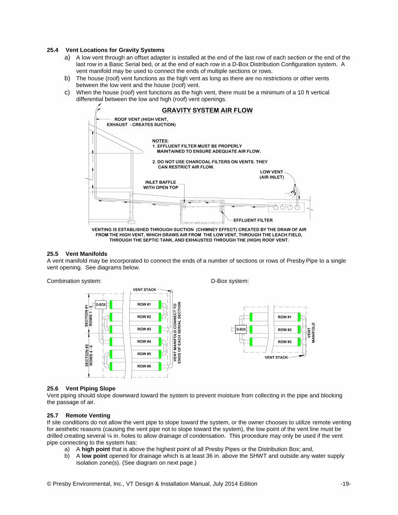
25.4 Vent Locations for Gravity Systems
a) A low vent through an offset adapter is installed at the end of the last row of each section or the end of the last row in a Basic Serial bed, or at the end of each row in a D-Box Distribution Configuration system. A vent manifold may be used to connect the ends of multiple sections or rows.
b) The house (roof) vent functions as the high vent as long as there are no restrictions or other vents between the low vent and the house (roof) vent.
c) When the house (roof) vent functions as the high vent, there must be a minimum of a 10 ft vertical differential between the low and high (roof) vent openings.
25.5 Vent Manifolds
A vent manifold may be incorporated to connect the ends of a number of sections or rows of Presby Pipe to a single vent opening. See diagrams below. Combination system: D-Box system: 25.6 Vent Piping Slope
Vent piping should slope downward toward the system to prevent moisture from collecting in the pipe and blocking the passage of air. 25.7 Remote Venting
If site conditions do not allow the vent pipe to slope toward the system, or the owner chooses to utilize remote venting for aesthetic reasons (causing the vent pipe not to slope toward the system), the low point of the vent line must be drilled creating several ¼ in. holes to allow drainage of condensation. This procedure may only be used if the vent pipe connecting to the system has:
a) A high point that is above the highest point of all Presby Pipes or the Distribution Box; and, b) A low point opened for drainage which is at least 36 in. above the SHWT and outside any water supply
isolation zone(s). (See diagram on next page.)
SE
CT
ION
#1
RO
WS
1 -
3S
EC
TIO
N #
2
RO
WS
4 -
6
ROW #1
ROW #2
ROW #3
ROW #4
ROW #5
ROW #6
VE
NT
MA
NIF
OL
D C
ON
NE
CT
TO
EN
DS
OF
EA
CH
SE
RIA
L S
EC
TIO
N
VENT STACK
VENT STACK
ROW #1
ROW #2
ROW #3
VE
NT
MA
NIF
OL
D
LOW VENT
(AIR INLET)
VENTING IS ESTABLISHED THROUGH SUCTION (CHIMNEY EFFECT) CREATED BY THE DRAW OF AIR
FROM THE HIGH VENT, WHICH DRAWS AIR FROM THE LOW VENT, THROUGH THE LEACH FIELD,
THROUGH THE SEPTIC TANK, AND EXHAUSTED THROUGH THE (HIGH) ROOF VENT.
ROOF VENT (HIGH VENT,
EXHAUST - CREATES SUCTION)
INLET BAFFLE
WITH OPEN TOP
EFFLUENT FILTER
NOTES:
1. EFFLUENT FILTER MUST BE PROPERLY
MAINTAINED TO ENSURE ADEQUATE AIR FLOW.
2. DO NOT USE CHARCOAL FILTERS ON VENTS. THEY
CAN RESTRICT AIR FLOW.
GRAVITY SYSTEM AIR FLOW

© Presby Environmental, Inc., VT Design & Installation Manual, July 2014 Edition -20-
Illustration of Remote Venting:
25.8 By-Pass Venting
REMOTE DIFFERENTIAL VENTING(NOT TO SCALE)
NO
T A
LL
RO
WS
AR
E S
HO
WN
SLOPE
LO
W V
EN
T
HIG
H V
EN
T
FINAL GRADE
HIGH GROUND WATER TABLE
SLOPESLO
PE
SLOPE
DISTRIBUTION BOX
2" MIN OVER
PRESBY
PIPE
HIGH GROUND WATER TABLE
10
' M
IN3
'
MIN
DRILL SEVERAL 1/4"Ø HOLES AT LOW POINT OF ELBOW
TO DRAIN CONDENSATION. LOW POINT MUST BE 3 FT.
ABOVE SEASONAL HIGH WATER TABLE AND MEET VT
HORIZONTAL SETBACKS TO REGULATED FEATURES.
DISGUISE
VENT IN TREEDISGUISE LOW
VENT IN SHRUBS
SCREEN VENT
OPENINGS
TOP OF
DISTRIBUTION BOX
WRAP WITH GEO-TEXTILE
FABRIC AND PLACE WASHED
STONE AROUND ELBOW
2" MIN. OVER
PRESBY PIPE
WRAP WITH GEO-TEXTILE
FABRIC AND PLACE WASHED
STONE AROUND ELBOW
SCH. 40 PVC OR EQUAL
RECOMMENDED FOR HIGH VENT

© Presby Environmental, Inc., VT Design & Installation Manual, July 2014 Edition -21-
26.0 Site Selection
26.1 Access
Systems should be located to allow access for septic tank maintenance and to at least one end of all Presby Rows. Planning for future access will facilitate Rejuvenation in the unlikely event the system malfunctions (see System Rejuvenation sect. 28.0, page 23). 26.2 Containment
Systems should not be located where structures such as curbs, walls or foundations might adversely restrict the soil’s ability to transport water away from the system. 26.3 Determining Site Suitability
Refer to Vermont Rules regarding site suitability requirements. 26.4 Hydraulic loading
Systems should not be located where lawn irrigation, roof drains, or natural flows increase water loading to the soils around the system. 26.5 Reserve Area
Vermont Rules require a reserve area for In-Ground replacement systems; mound systems do not require a reserve area and replacement system can be installed in the same location. In-Ground systems must be replaced in accordance with Vermont rules and may require the replacement system to be located in the reserve area. 26.6 Rocky or Wooded Areas
Avoid locating systems in rocky or wooded areas that require additional site work, since this may alter the soil’s ability to accept water. No trees or shrubs should be located within 10 ft of the system to prevent root infiltration. 26.7 Systems under Traffic Bearing Surfaces
The State of Vermont does not permit systems to be installed under traffic bearing surfaces. 26.8 Surface Water Diversions
Surface water runoff must be diverted away from the system. Diversions must be provided up-slope of the system and designed to avoid ponding. Systems must not be located in areas where surface or groundwater flows are concentrated. 26.9 Topography
Locate systems on convex, hill, slope or level locations that do not concentrate surface flows. Avoid swales, low areas, or toe-of-slope areas that may not provide sufficient drainage away from the system. 27.0 Component Handling, Site Preparation and Installation Requirements
27.1 Backfilling Rows
a) Spread System Sand between the rows. b) If using AES, confirm pipe rows are positioned with Bio-Accelerator® along the bottom (sewn seam up). c) Stand between two rows of pipe and walk heel-to-toe its entire length, ensuring that System Sand fills all
void spaces beneath the Presby Pipe. d) Finish spreading System Sand to the top of the rows and leave them exposed for inspection purposes. e) After inspect, apply at least 6 in. of additional System Sand over all the Presby pipes. f) A minimum of 4 in. of suitable earth cover (topsoil or loam), with a texture similar to the soil at the site and
capable of sustaining plant growth, must be placed above the installed system. Refer to Topsoil (sect. 12.26, page 9).
g) Construction equipment should not travel over the installed system area until at least 12 in. of cover material is placed over the Presby Pipes.
h) Final grades must direct precipitation away and around the field. Crown the top of level beds enough to shed water.
27.2 Component Handling
a) Keep mud, grease, oil, etc. away from all components. b) Avoid dragging pipe through wet or muddy areas. c) Store pipe on high and dry areas to prevent surface water and soil from entering the pipes or
contaminating the fabric prior to installation.

© Presby Environmental, Inc., VT Design & Installation Manual, July 2014 Edition -22-
d) The outer fabric of the Presby Pipe is ultra-violet stabilized; however, this protection breaks down over time in direct sunlight. To prevent damage to the fabric, cover the pipe with an opaque tarp if stored outdoors.
27.3 Connect Rows Using Raised Connections
Raised connections consist of offset adapters, 4 in. PVC sewer and drain pipe, and 90° elbows. They enable greater liquid storage capacity and increase the bacterial surfaces being developed. Use raised connections to connect the rows of the Presby System (see sect. 4.5, page 4 ). 27.4 Correct Alignment of Advanced Enviro-Septic® Bio-Accelerator® Fabric
The Bio-Accelerator® (white geo-textile fabric) is to be positioned centered along the bottom of the pipe rows (sewn seam up). 27.5 Critical Reminder Prevent Soil Compaction
It is critical to keep excavators, backhoes, and other equipment off the excavated or tilled surface of a bed. Before installing the System Sand, excavation equipment should be operated around the bed perimeter; not on the bed itself. 27.6 Distribution Box Installation
To prevent movement, be sure D-boxes are placed level on compacted soil, sand, pea gravel base, or concrete pad. 27.7 Erosion Control
To prevent erosion, soil cover above the system shall be planted with native, shallow-rooted vegetation such as grass, wildflowers and certain perennials or ground covers. 27.8 Fill Extensions Requirements
All Presby Systems with any portion of the System Sand bed above original grade require fill extensions on each side beyond the outside edge of all pipes starting at the edge of the System Sand then tapering to meet existing grade at a maximum slope of 3:1 (see illustrations in sect. 3.0, page 3). 27.9 Level Row Tolerances
Use a laser level or transit to install rows level. Variations beyond 1 in. (±1/2") may affect system performance and are not acceptable. 27.10 Raking and Tilling Procedures All areas receiving System Sand, sand fill and fill extensions must be raked or tilled. If a backhoe/excavator is used
to till the site, fit it with chisel teeth and till the site. The excavator should remain outside of the proposed System Sand area and extensions. Equipment with tires must never enter the receiving area due to likely wheel compaction of underlying soil structures.
a) For in-ground bed systems, excavate the system bed as necessary below original grade. Using an
excavator or backhoe, tilt the bucket teeth perpendicular to the bed and use the teeth to rake furrows 2 in.- 6 in. deep into the bottom of the entire area receiving System Sand or sand fill (“receiving area”).
b) For elevated bed systems remove the “O” horizon (all organics), then use an excavator or backhoe to
rake furrows 7 in. – 8 in. deep into the receiving area. Create a transition layer by tilling 6 in. of System Sand or sand fill into the receiving layer prior to bed construction.
27.11 Row Spacers
System Sand may be used to keep pipe in place while covering, but simple tools may also be constructed for this purpose. Two examples are shown. One is made from rebar, the other from wood. Center-to-center row spacing may be larger than specified by this manual. Caution: Remove all tools used as row spacers before final covering. 27.12 Site Preparation
a) Locate and stake out the System Sand bed, extension areas and soil material cover extensions on the site according to the approved plan.
b) Install sediment/erosion control barriers prior to beginning excavation to protect the system from surface water flows during construction.
c) Do not travel across or locate excavation equipment within the portion of the site receiving System Sand. d) Do not stockpile materials or equipment within the portion of the site receiving System Sand. e) It is especially important to avoid using construction equipment down slope of the system to prevent soil
compaction.
BERM SAND AT BASE OF
PIPES TO HOLD IN PLACE
WOODEN FRAME REBAR FRAME
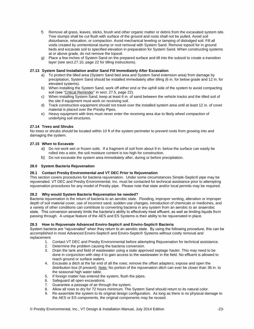
© Presby Environmental, Inc., VT Design & Installation Manual, July 2014 Edition -23-
f) Remove all grass, leaves, sticks, brush and other organic matter or debris from the excavated system site. Tree stumps shall be cut flush with surface of the ground and roots shall not be pulled. Avoid soil disturbance, relocation, or compaction. Avoid mechanical leveling or tamping of dislodged soil. Fill all voids created by unintentional stump or root removal with System Sand. Remove topsoil for in ground beds and excavate soil to specified elevation in preparation for System Sand. When constructing systems at or above grade, do not remove the topsoil.
g) Place a few inches of System Sand on the prepared surface and till into the subsoil to create a transition layer (see sect.27.10, page 22 for tilling instructions).
27.13 System Sand Installation and/or Sand Fill Immediately After Excavation
a) To protect the tilled area (System Sand bed area and System Sand extension area) from damage by precipitation, System Sand should be installed immediately after tilling (6 in. for below grade and 12 in. for elevated systems).
b) When installing the System Sand, work off either end or the uphill side of the system to avoid compacting soil (see “Critical Reminder” in sect. 27.5, page 22).
c) When installing System Sand, keep at least 6 in. of sand between the vehicle tracks and the tilled soil of the site if equipment must work on receiving soil.
d) Track construction equipment should not travel over the installed system area until at least 12 in. of cover material is placed over the Presby Pipes.
e) Heavy equipment with tires must never enter the receiving area due to likely wheel compaction of underlying soil structures.
27.14 Trees and Shrubs
No trees or shrubs should be located within 10 ft of the system perimeter to prevent roots from growing into and damaging the system. 27.15 When to Excavate
a) Do not work wet or frozen soils. If a fragment of soil from about 9 in. below the surface can easily be rolled into a wire, the soil moisture content is too high for construction.
b) Do not excavate the system area immediately after, during or before precipitation. 28.0 System Bacteria Rejuvenation
28.1 Contact Presby Environmental and VT DEC Prior to Rejuvenation
This section covers procedures for bacteria rejuvenation. Under some circumstances Simple-Septic® pipe may be rejuvenated. VT DEC and Presby Environmental, Inc. must be contacted for technical assistance prior to attempting rejuvenation procedures for any model of Presby pipe. Please note that state and/or local permits may be required. 28.2 Why would System Bacteria Rejuvenation be needed?
Bacteria rejuvenation is the return of bacteria to an aerobic state. Flooding, improper venting, alteration or improper depth of soil material cover, use of incorrect sand, sudden use changes, introduction of chemicals or medicines, and a variety of other conditions can contribute to converting bacteria in any system from an aerobic to an anaerobic state. This conversion severely limits the bacteria’s ability to effectively treat effluent, as well as limiting liquids from passing through. A unique feature of the AES and ES Systems is their ability to be rejuvenated in place. 28.3 How to Rejuvenate Advanced Enviro-Septic® and Enviro-Septic® Bacteria
System bacteria are “rejuvenated” when they return to an aerobic state. By using the following procedure, this can be accomplished in most Advanced Enviro-Septic® and Enviro-Septic® Systems without costly removal and replacement.
1. Contact VT DEC and Presby Environmental before attempting Rejuvenation for technical assistance. 2. Determine the problem causing the bacteria conversion. 3. Drain the tank and field of wastewater using a state approved septage hauler. This may need to be
done in conjunction with step 4 to gain access to the wastewater in the field. No effluent is allowed to reach ground or surface waters.
4. Excavate a ditch at the far end of all the rows; remove the offset adapters; expose and open the distribution box (if present). Note: No portion of the rejuvenation ditch can ever be closer than 36 in. to the seasonal high water table.
5. If foreign matter has entered the system, flush the pipes. 6. Safeguard all open excavations. 7. Guarantee a passage of air through the system. 8. Allow all rows to dry for 72 hours minimum. The System Sand should return to its natural color. 9. Re-assemble the system to its original design configuration. As long as there is no physical damage to
the AES or ES components, the original components may be reused.

© Presby Environmental, Inc., VT Design & Installation Manual, July 2014 Edition -24-
29.0 System Expansion
29.1 Presby Systems are Expandable
Presby Systems are easily expanded by adding equal lengths of pipe to each row of the original design, by adding additional rows or by adding additional equal sections. All system expansions must comply with State and local regulations. Contact VT DEC prior to commencement of any work to obtain required permits. 29.2 Reusable Components
Presby Pipe and components are not biodegradable and may be reused. In cases of improper installation it may be possible to excavate, clean, and reinstall all system components. 30.0 System Replacement
30.1 System Replacement Procedure
If a Presby System requires replacement: a) Contact VT DEC prior to commencement of any work to obtain required permits. b) Remove the existing components and contaminated sand. c) Replace in the same excavated location with new System Sand. d) If components are not damaged, they may be flushed and reused. e) All system replacements must comply with State and Local regulations.
31.0 Operation & Maintenance
31.1 Proper Use
Presby Systems require minimal maintenance, provided the system is not subjected to abuse. An awareness of proper use and routine maintenance will guarantee system longevity. We encourage all system owners and service providers to obtain and review a copy of our Owner’s Manual, available from our website
www.PresbyEnvironmental.com or via mail upon request to (800) 473-5298 or [email protected]. 31.2 System Abuse Conditions
The following conditions constitute system abuse: a) Liquid in high volume (excessive number of occupants, excessive use of water in a short period of time,
leaking fixtures, whirlpool tubs, hot tubs, water softening equipment or additional water discharging fixtures if not specified in system design).
b) Solids in high volume (excessive number of occupants, paper products, personal hygiene products, garbage disposals or water softening equipment if not specified in system design)
c) Antibiotic medicines in high concentrations d) Cleaning products in high concentrations e) Fertilizers or other caustic chemicals in any amount f) Petroleum products in any amount g) Latex and oil paints h) System suffocation (compacted soils, barrier materials, etc.)
Special Note: Presby Environmental, Inc., and most regulatory agencies do not recommend the use of septic system additives.
31.3 System Maintenance/Pumping of the Septic Tank
a) Inspect the septic tank at least once every two years under normal usage. b) Pump the tank when surface scum and bottom sludge occupy one-fourth or more of the liquid depth of the
tank. c) If a garbage disposal is used, the septic tank will likely require more frequent pumping. d) After pumping, inspect the septic tank for integrity to ensure that no groundwater is entering it. Also check
the integrity of the tank inlet and outlet baffles and repair if needed. e) Inspect the system to ensure that vents are in place and free of obstructions. f) Effluent filters require ongoing maintenance due to their tendency to clog and cut off oxygen to the
System. Follow filter manufacturer’s maintenance instructions and inspect filters frequently.
31.4 Site Maintenance
It is important that the system site remain free of shrubs, trees, and other woody vegetation to within a minimum of 10 ft of the system, including the entire System Sand bed area, and areas impacted by side slope tapering and perimeter drains (if used). Roots can infiltrate and cause damage or clogging of system components. If a perimeter drain is used, it is important to make sure that the outfall pipes are screened to prevent animal activity. Also check outfall pipes regularly to ensure that they are not obstructed in any way.

© Presby Environmental, Inc., VT Design & Installation Manual, July 2014 Edition -25-
32.0 Glossary
This Manual contains terminology which is common to the industry and terms that are unique to Presby Systems. While alternative definitions may exist, this section defines how these terms are used in this Manual. 32.1 Basic Serial Distribution
Basic Serial distribution incorporates Presby Rows in serial distribution in a single bed. See Basic Serial Distribution in sect. 13.0, page 10. 32.2 Bio-Accelerator®
Bio-Accelerator® fabric screens additional solids from the effluent, enhances and accelerates treatment, facilitates quick start-up after periods of non-use, provides additional surface area for bacterial growth, promotes even distribution, and further protects outer layers and the receiving surfaces so they remain permeable. Bio-Accelerator® is only available with Advanced Enviro-Septic® (see sect. 32.24, page 26). 32.3 Butterfly Configuration
A variation of a standard, single bed system with the D-box located in the center, with rows oriented symmetrically on either side, and with each side or section receiving an equal volume of flow from the D-Box. See Butterfly Configuration, sect. 14.0, page 10. 32.4 Center-to-Center Row Spacing
Center-to-center spacing is the distance from the center of one Presby Row to the center of the adjacent row. 32.5 Coarse Randomized Fiber
A mat of coarse, randomly-oriented fibers (AES & ES only) which separates more suspended solids from the effluent, provides a large surface area for bacterial activity and keeps the biomat, which develops in the geo-textile fabric, from being in direct contact with the pipe (see illustration in sect. 1.0, page 1). 32.6 Combination Serial Distribution
Combination Serial Distribution incorporates two or more sections of Presby Pipe in a single bed, with each section receiving a maximum of 500 GPD of effluent from a distribution box (see sect. 15.0, page 11). 32.7 Cooling Ridges
Pipe ridges that allow the effluent to flow uninterrupted around the circumference of the pipe and aid in cooling (see illustration in sect. 1.0, page 1). 32.8 Coupling
A plastic fitting that joins two Presby Pipe pieces in order to form rows. See sect.4.4, page 4. 32.9 Daily Design Flow
The peak daily flow of wastewater to a system, expressed in gallons per day (GPD); systems are typically sized based on the daily design flow. Design flow calculations are set forth in the Vermont Rules. In general, actual daily use is expected to be one-half to two-thirds less than “daily design flow.” 32.10 Differential Venting
A method of venting a Presby System utilizing high and low vents (see sect. 25.2, page 18). 32.11 Distribution Box or “D-Box”
A device designed to divide and distribute effluent from the septic tank equally to each of the outlet pipes that carry effluent into the Presby System. D-Boxes are also used for velocity reduction, see Velocity Reduction, sect. 24.6, page 18. 32.12 D-Box Distribution Configuration
D-Box distribution configuration is a design in which each Presby Row receives effluent from a distribution box outlet. Such a system is also called a “parallel system” or a “finger system.” See D-Box (Parallel) Distribution, sect. 14.0, page 10. 32.13 Distribution Box Manifold
A distribution box manifold is a PVC configuration which connects several distribution box outlets together in order to equalize effluent flow. Refer to drawing in sect. 12.5, page 6. 32.14 End-to-End Configuration
Consists of two or more beds constructed in a line (i.e., aligned along the width of the beds). See sect. 17.0, page 12.

© Presby Environmental, Inc., VT Design & Installation Manual, July 2014 Edition -26-
32.15 Fill Extension
Utilized in constructing Elevated (mound) Systems and blend the raised portion of the system with side slope tapering to meet the existing grade. All systems require 1.5 ft minimum fill extension on all sides (measured from the edge of the Presby pipes). 32.16 Flow Equalizer
An adjustable plastic insert installed in the outlet pipes of a D-Box to equalize effluent distribution to each outlet. 32.17 GPD and GPM
GPD and GPM are acronyms for "gallons per day" and "gallons per minute" respectively. 32.18 High and Low Vents
Pipes used in differential venting. Detailed information about venting requirements can be found in Venting Requirements, sect. 25.0, page 18. 32.19 MPI
MPI is an acronym for minutes per inch and is the numerical value by which percolation rates (also called “perc rates”) are expressed. 32.20 Multiple Bed Distribution
Multiple bed distribution incorporates two or more beds, each bed with Basic Serial, Combination Serial, or D-Box distribution and receiving effluent from a distribution box (see sect. 17.0, page 12). 32.21 Non-Conventional Configurations
Have irregular shapes or row lengths shorter than 30 ft to accommodate site constraints (see sect. 22.0, page 15. 32.22 Offset Adapter
A plastic fitting with a 4 in. hole installed at the 12 o’clock position which allows for connections from one row to another and for installation of venting (see sect. 4.2, page 4). 32.23 Percolation Rate
Also known as "perc rate" is a numerical indication of a soil’s hydraulic capacity, expressed in minutes per inch (MPI.) 32.24 Advanced Enviro-Septic® (AES) Pipe
A single unit comprised of corrugated plastic pipe, Bio-Accelerator® (see sect. 32.2, page 25) fabric along its bottom which is surrounded by a layer of randomized plastic fibers and a sewn geo-textile fabric, is 10 ft in length, with an outside diameter of 12 in. and a storage capacity of approximately 58 gallons. Each foot of Advanced Enviro-Septic® provides over 40 sq ft of total surface area for bacterial activity. The sewn seam is always oriented up (12 o'clock position) within the bed. A white tag is sewn into the seam indicating the product is Advanced Enviro-Septic® pipe. Pipes are joined together with couplings to form rows. AES is a combined wastewater treatment and dispersal system (see illustration in sect.2.0, page 2). 32.25 Enviro-Septic® (ES) Pipe
A single unit comprised of corrugated plastic pipe which is surrounded by a layer of randomized plastic fibers and a sewn geo-textile fabric, is 10 ft in length, with an outside diameter of 12 in. and a storage capacity of approximately 58 gallons. Each foot of Enviro-Septic® provides over 25 sq ft of total surface area for bacterial activity. A white tag is sewn into the seam indicating the product is Enviro-Septic® pipe. Pipes are joined together with couplings to form the rows. ES is a combined wastewater treatment and dispersal system (see illustration in sect.2.0, page 2). 32.26 Simple-Septic® (SS) Pipe
A single unit comprised of corrugated plastic pipe which is surrounded by a single layer of sewn geo-textile fabric, is 10 ft. in length, with an outside diameter of 12 in. and a storage capacity of approximately 58 gallons. A white tag is sewn into the seam indicating the product is Simple-Septic® pipe. Pipes are joined together with couplings to form rows. Simple-Septic® is a wastewater treatment system placed after primary treatment by a septic tank. Simple-Septic® has the benefits of Presby’s other proprietary features such as patented skimmer tabs and cooling ridges which protect the bacterial surface area of the fabric. Each foot of Simple-Septic® pipe provides over 15 sq ft of total surface area for bacterial activity. Due to the limited surface area of SS as compared to AES and ES, please contact Presby Environmental, Inc. if rejuvenation is required.
© Presby Environmental, Inc., VT Design & Installation Manual, July 2014 Edition -27-
32.27 Pressure Distribution
A pressurized, small-diameter pipe system used to deliver effluent to an absorption field. Pressure Distribution is not permitted to be used with the Presby System. Presby Systems are designed to promote even distribution without the need for pressure distribution. 32.28 Pump Systems
Utilize a pump to gain elevation in order to deliver effluent to a D-Box, see sect. 24.0, page 17. 32.29 Raised Connection
A U-shaped, 4” diameter, PVC pipe configuration which is used to connect rows oriented in a serial configuration and to maintain the proper liquid level inside each row. See drawing in sect. 4.5, page 4. 32.30 Raking and Tilling
Raking and tilling refers to methods of preparing the native soil that will be covered with System Sand or Sand Fill, creating a transitional layer between the sand and the soil (see sect. 27.9, page 22). 32.31 Row
A row consists of a number of Presby Pipe sections (sticks) connected by couplings with an Offset Adapter on the inlet end and an Offset Adapter on the opposite end. Rows are typically between 30 ft and 100 ft long. 32.32 Sand Fill
Clean sand, free of organic materials and meeting the specifications set forth in Sand Fill, sect.12.24, page 9. Sand fill is used to raise the elevation of the system to meet required separation distance or in side slope tapers. System Sand may be used in place of Sand Fill. 32.33 Section / Serial Section
A serial section is a group of interconnected rows receiving effluent from one distribution box outlet. Sections are limited to 500 GPD daily design flow and 500 ft total Presby Pipe maximum. 32.34 Serial Distribution
Serial distribution is when two or more Presby Rows are connected by a Raised Connection. Basic Serial distribution is described in sect. 13.0, page 10, Combination Serial distribution is described in sect. 15.0, page 11. 32.35 SHWT
SHWT is an acronym for seasonal high water table. 32.36 Skimmer Tabs
Projections into the Presby Pipe that help to capture grease and suspended solids from the existing effluent (see illustration in sect. 1.0, page 1). 32.37 Side-to-Side Configuration
Consist of two or more beds arranged so that the rows are parallel to one another. 32.38 Slope (3:1)
In this Manual's illustrations, slope is expressed as a ratio of run to rise. Example: A slope with a grade of (3:1) is the difference in horizontal distance of three (3) horizontal feet (run) over an elevation difference of one (1) ft (rise). 32.39 Slope (%) Expressed as a percent, is the difference in elevation divided by the difference in horizontal distance between two
points on the surface of a landform. Example: A site slope of one (1) percent is the difference in elevation of one (1) foot (rise) over a horizontal distance of one hundred (100) feet (run). 32.40 Smearing
Smearing is the mechanical sealing of soil air spaces along an excavated, tilled or compressed surface. This is also referred to as “compacting.” In all installations, it is critical to avoid smearing or compacting the soils under and around the field. 32.41 Surface Diversion
Surface diversion is a natural or manmade barrier that changes the course of water flow around an onsite system’s soil absorption field.

© Presby Environmental, Inc., VT Design & Installation Manual, July 2014 Edition -28-
32.42 System Sand Bed
The System Sand bed is the sand area required/used in Presby Systems. The System Sand bed extends a minimum of 6 in. below (in-ground systems), 12 in. below (mound systems), 6 in. above and 12 in. horizontally from the outside edges of the pipes in the system.
32.43 System Sand
System Sand must be clean, granular sand free of organic matter and must adhere to Vermont §1-913(c),(2) fill material with no more than 3% passing the #200 sieve (see complete details in sect. 12.23, page 9). 32.44 System Sand Extension Area
The System Sand extension is any portion of the System Sand bed that is more than 1 ft away from Presby Pipe. The System Sand extension area is a minimum of 6 in. deep. A System Sand extension area is required on the down slope side of mound systems with more than 10% slope and extends a minimum of 3 ft beyond the tall portion of the down slope edge of the System Sand bed (see illustration in sect. 3.0, page 3). This shouldn't be confused with the Fill Extension (see sect. 32.15, page 26). 32.45 Topsoil (a.k.a. Loam or Soil Cover Material)
Topsoil, also known as Loam, is soil material cover capable of sustaining plant growth which forms the topmost layer of cover material above the system.

© Presby Environmental, Inc., VT Design & Installation Manual, July 2014 Edition -29-
33.0 Vermont System Installation Form
Installers must complete and fax or mail a copy of this form to the local approving authority and to: Presby Environmental, Inc., 143 Airport Rd, Whitefield, NH 03598 Fax: (603) 837-9864
Installer’s Name:
Installer’s PEI Certification Number:
Company Name:
Street Address:
City:
State: Zip:
Installer’s Phone Number:
Designer’s Name:
Company Name:
Street Address:
City: State: Zip:
Phone Number:
Property Owner(s):
Site Street Address:
City:
State: Zip:
System Information (check all that apply): Advanced Enviro-Septic® Pipe Enviro-Septic® Pipe Simple-Septic® Pipe
New Construction Replacement Mound In ground Gravity Sloping Gravity Pump to D-Box Serial Distribution Combination Distribution Parallel Distribution # of Beds: ___________ Effluent Filter Used Design Flow (bedrooms or GPD):_____________ Perc Rate: ___________
Installation Date:
System Startup Date:
State Permit Number: Local Construction Permit Number:
Comments: