the performance-optimized and easy-to-use servo drive...
TRANSCRIPT

siemens.com/sinamics-v90
SINAMICS V90The performance-optimized and easy-to-use servo drive system
2
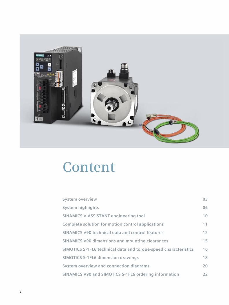
Content
System overview 03
System highlights 06
SINAMICS V-ASSISTANT engineering tool 10
Complete solution for motion control applications 11
SINAMICS V90 technical data and control features 12
SINAMICS V90 dimensions and mounting clearances 15
SIMOTICS S-1FL6 technical data and torque-speed characteristics 16
SIMOTICS S-1FL6 dimension drawings 18
System overview and connection diagrams 20
SINAMICS V90 and SIMOTICS S-1FL6 ordering information 22
3
SINAMICS V90 and SIMOTICS S-1FL6 Belonging to two comprehensive drive technology families
SINAMICS V90 is the new member of the SINAMICS drive family, and SIMOTICS S-1FL6 is the new member of the SIMOTICS motor family. Together, they form an optimized servo drive system for positioning, as well as speed and torque control. Through its optimized design, the system ensures high servo performance in a cost-efficient and easy way as well as a high degree of ruggedness.
SIMOTICS stands for:• 125 years of experience in building electric motors• Optimum solutions in all sectors, regions and perfor-
mance classes• Innovative motor technologies with the highest quality
and reliability• Highest dynamic performance, precision and efficiency –
but still extremely compact
The complete range for all application consists of:• SIMOTICS low-voltage motors – high-efficiency up to
1250 kW• SIMOTICS motion control motors – highest dynamic
performance and precision• SIMOTICS DC motors – the pioneers in DC motors• SIMOTICS high-voltage motors – maximum efficiency
and reliability
SINAMICS and SIMOTICS products are part of Siemens Integrated Drive Systems. Drive technology based on Integrated Drive Systems ensures maximum productivity, energy-efficiency, and reliability in any automation envi-ronment and throughout the entire lifecycle.
SIMOTICS motors provide you with an ideal solution for any application. They are the most comprehensive range of electric motors worldwide.
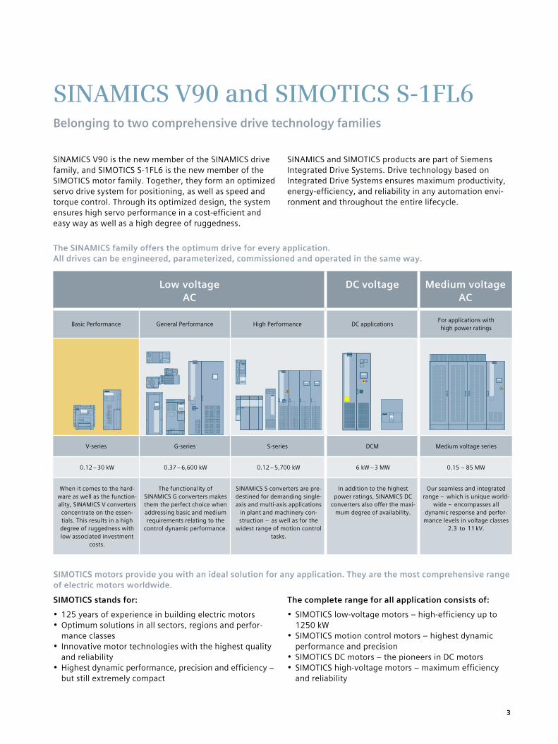
The SINAMICS family offers the optimum drive for every application. All drives can be engineered, parameterized, commissioned and operated in the same way.
Low voltage AC
DC voltage Medium voltage AC
Basic Performance General Performance High Performance DC applications For applications with high power ratings
V-series G-series S-series DCM Medium voltage series
0.12 – 30 kW 0.37 – 6,600 kW 0.12 – 5,700 kW 6 kW – 3 MW 0.15 – 85 MW
When it comes to the hard-ware as well as the function-ality, SINAMICS V converters
concentrate on the essen-tials. This results in a high degree of ruggedness with low associated investment
costs.
The functionality of SINAMICS G converters makes them the perfect choice when addressing basic and medium requirements relating to the
control dynamic performance.
SINAMICS S converters are pre-destined for demanding single-axis and multi-axis applications
in plant and machinery con-struction – as well as for the
widest range of motion control tasks.
In addition to the highest power ratings, SINAMICS DC
converters also offer the maxi-mum degree of availability.
Our seamless and integrated range – which is unique world-
wide – encompasses all dynamic response and perfor-mance levels in voltage classes
2.3 to 11 kV.
4
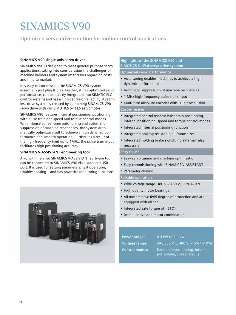
SINAMICS V90 single-axis servo drives
SINAMICS V90 is designed to meet general purpose servo applications, taking into consideration the challenges of machine builders and system integrators regarding costs and time to market.
It is easy to commission the SINAMICS V90 system – essentially just plug & play. Further, it has optimized servo performance, can be quickly integrated into SIMATIC PLC control systems and has a high degree of reliability. A seam- less drive system is created by combining SINAMICS V90 servo drive with our SIMOTICS S-1FL6 servomotor.
SINAMICS V90 features internal positioning, positioning with pulse train and speed and torque control modes. With integrated real-time auto tuning and automatic suppression of machine resonances, the system auto- matically optimizes itself to achieve a high dynamic per-formance and smooth operation. Further, as a result of the high frequency limit up to 1MHz, the pulse train input facilitates high positioning accuracy.
SINAMICS V-ASSISTANT engineering tool
A PC with installed SINAMICS V-ASSISTANT software tool can be connected to SINAMICS V90 via a standard USB port. It is used for setting parameters, test operation, troubleshooting – and has powerful monitoring functions.
SINAMICS V90Optimized servo drive solution for motion control applications
Highlights of the SINAMICS V90 and SIMOTICS S-1FL6 servo drive system:
Optimized servo performance
• Auto tuning enables machines to achieve a high dynamic performance
• Automatic suppression of machine resonances
• 1 MHz high-frequency pulse train input
• Multi-turn absolute encoder with 20-bit resolution
Cost-effective
• Integrated control modes: Pulse train positioning, internal positioning, speed and torque control modes
• Integrated internal positioning function
• Integrated braking resistor in all frame sizes
• Integrated holding brake switch, no external relay necessary
Easy to use
• Easy servo tuning and machine optimization
• Easy commissioning with SINAMICS V-ASSISTANT
• Parameter cloning
Reliable operation
• Wide voltage range 380 V ~ 480 V, -15% /+10%
• High quality motor bearings
• All motors have IP65 degree of protection and are equipped with oil seal
• Integrated safe torque off (STO)
• Reliable drive and motor combination
Power range: 0.4 kW to 7.0 kW
Voltage range: 3AC 380 V ... 480 V (-15% / +10%)
Control modes: Pulse train positioning, internal positioning, speed, torque

5
SIMOTICS S-1FL6Optimized servomotor solution for motion control applications
SIMOTICS S-1FL6 servomotors
SIMOTICS S-1FL6 are naturally cooled, permanent-magnet synchronous motors where the heat is dissipated through the motor surface. The motors can be simply and quickly installed using the full thread and quick- release connectors• 3 shaft heights: 45mm, 65mm, 90mm• Rated torques from 1.27 Nm up to 33.40 Nm• Rated speed of 2000 or 3000 rpm• Incremental encoders TTL 2500 S/R (13-bit resolution)
and absolute encoders ( 20-bit resolution) are available• Degree of protection IP65, natural cooling• Optional holding brake• With plain shaft or feather key
The motors have a 300 percent overload capability and can be combined with the SINAMICS V90 drives to create a powerful servo system with high functionality. Incre-mental or absolute encoders can be selected depending on the application. SIMOTICS S-1FL6 motors have a high
degree of dynamic performance, wide speed control range and high shaft end and flange precision.
Typical applications• Handling machines
e.g. pick & place machines• Packaging machines
e.g. labeling machines horizontal packaging machines
• Automatic assembly machines• Metal forming machines• Printing machines
e.g. screen printing machines• Winders and unwinders

6
⋯⋯
Cost-effectiveMany integrated functions to reduce machine costs
Integrated control modes
Pulse train input position control mode (PTI), internal position control mode (IPos), speed control mode and torque control are all inte-grated in the SINAMICS V90.
The drive has various integrated control modes to address a wide range of applications.
Integrated positioning function
• Position, speed, and acceleration setpoints can be entered
• Integrated referencing function• Feed forward and feed backward – or a com-
bination of digital inputs to select position • Positioning step enable from external digital
input• Absolute and relative positioning
Point-to-point positioning possible using a PLC without positioning functionality.
Integrated braking resistor for all frame sizes
Braking resistor is integrated for all frame sizes to dissipate the regenerative power for fast braking.
Most applications can be realized without an additional braking resistor.
Integrated holding brake switch
Integrated holding brake switch – the brake can be directly connected to the drive if a motor with holding brake is used.
Holding brake can be connected without requiring an external relay.
DI signal
Pulse
Analog input
Position 1
Position 2
Pulse counter
Speed/torque
V90 servo drive
Positioning function
Positioning function
Advanced PLC
Basic PLC
Braking resistor
Holding brakeExternal relay not required

7
Advanced auto tuning
Control loop parameters are optimized auto-matically. This function can be used when commissioning the system and in operation for changing loads.
This allows machines to achieve a high dynamic performance and smooth opera-tion in a wide range of applications.
Automatic suppression of machine resonances
When this function is activated the drive iden-tifies mechanical resonance frequencies and automatically suppresses these using a filter. Vibration and noise during operation are reduced.
This ensures a high dynamic response of the machine while decreasing machine vibration.
1MHz pulse train setpoint and 20-bit encoder resolution
The command pulse train input operate at the high frequency up to 1MHz and the feedback absolute encoder available with 20 bit resolution.
Makes the machine to reach high positioning accuracy and low speed ripple.
Optimized servo performanceQuick, smooth and precise positioning
Optimized system performance
• 300 percent overload capability of drive and motor
• Low motor torque ripple• Motor and drive are perfectly coordinated
with one another
Fast acceleration and braking while main-taining a smooth running system to ensure high machine productivity.
n
t
n
t
n
t
n
t
n
Setting time Setting time
Auto tuning
Gain(dB) Gain(dB)
f(Hz)f(Hz)Notch frequency
200 kHz
1 MHz
Torque
Time
Time
300%MN
SpeedFaster acceleration

8
n
t
Amplifer internal settingPositioning data 10
Position loop gainSpeed loop gain
…..Speed loop integral time
Easy servo tuning and machine optimization
The system can be automatically optimized using the auto tuning function and automatic suppression of machine resonances.
Simply plug & play, no in-depth servo know-how required.
Easy commissioning using the SINAMICS V-ASSISTANT engineering tool
Graphic screen forms guide the user when set-ting application-specific parameters; intuitive drive and motor status check; integrated trace and measuring functionality.
SINAMICS V-ASSISTANT makes commission-ing and diagnostics quick and easy.
Simple connection to a control system
Two channel pulse train for position setpoint, one exclusively for 5V differential (RS422 standard), one for 24V single ended signal.
Standard interface makes it easy to couple the drive with PLCs and motion controllers.
Optimized connection system for easy use
• Orientable connectors on motor side• Quick-release coupling for encoder and
brake connectors (bayonet lock)• Coded connectors for protection against
polarity reversal• Easy cable selection and ordering system
Easy to useSimple tuning and quick commissioning
Parameter cloning
SINAMICS V90 servo drives have a standard SD card slot, parameter setting can be easily transferred between drive devices.
Efficient commissioning of serial machines.
SD
Commissioning Tuning OptimizingDynamic factor
Machine rigidity
High
Med
Low
Setting time
5V differential signal
24V single ended signal
Motion controller
PLC
Copy parameters
Commissioning

9
Can withstand harsh environments
• Wider voltage range 380 V ~ 480 V, -15% / +10%
• Coated PCB increases robustness of the drive to cope with harsh environments
• Motor is equipped with high-quality bearings
High degree of motor protection
• SIMOTICS S-1FL6 motors have degree of protection IP65 as standard - this includes the connectors on motor side
• Oil seal at shaft end as standard• High quality metal motor connector
Integrated safety function STO (safe torque off)
The STO (safe torque off) function is a stan-dard feature of all SINAMICS V90 servo drives. This function prevents the motor from moving unexpectedly and complies with safety stan-dard SIL2 (EN618005-2). This safety function-ality can be realized without additional components.
Reliable operationRobust design and safe choice
Protected against water jets No ingress of dust
323V~528V
t
v STO
IP 6 5
DustWater

10
SINAMICS V-ASSISTANTEasy-to-use engineering tool for commissioning and diagnostics
• Intuitive menu navigation provides a clear overview of the commissioning workflow
• Simple commissioning with point-to-point communication via USB interface
• Graphic screen forms guide the user when setting application-specific parameters
• High degree of usability: – compact
Graphic screen so that users can quickly and simply configure machinesUser task-centric design for prompted machine commissioning
Trace function to monitor the drive and motor statusGraphic view to monitor the digital inputs/outputs and other control signals
– can be downloaded from the SINAMICS V90 internet page: www.siemens.com/sinamics-v90
– languages can be toggled on-the-fly• Advanced tools such as the trace function, machine-
measuring function, servo tuning function and control panel are available to optimize the machine perfor-mance and for diagnostics
• Convenient data handing for commissioning series machines and archiving different machine versions

11
Complete solution for motion control applications
With SINAMICS V90 and SIMOTICS S-1FL6, the optimized servo drive system – together with SIMATIC Panel, SIMATIC PLC and SINAMICS V20 – SIEMENS is offering comprehensive solutions from a single source for general motion control applications. Typical sectors include tex-tiles, packaging, material handling – as well as many others.
SIMATIC Panel SIMATIC PLC
SINAMICS V20
SINAMICS V90
SIMOTICS S-1FL6
Ethernet/PROFINET USS MODBUS RTU
PC
Pulse/Analog

12
SINAMICS V90Technical data
Technical dataArticle No. 6SL3210-5FE 10-4UA0 10-8UA0 11-0UA0 11-5UA0 12-0UA0 13-5UA0 15-0UA0 17-0UA0Frame size FSAA FSA FSB FSCRated power (kW) 0.40 0.75 1.00 1.50 2.00 3.50 5.00 7.00Rated output current (A) 1.2 2.1 3.0 5.3 7.8 11.0 12.6 13.2Max. output current (A) 3.6 6.3 9.0 15.9 23.4 33.0 37.8 39.6
Line supplyVoltage 3AC 380V … 480V, (-15% / +10%)Frequency 50/60Hz, (-10% / +10%))Capacity (kVA) 1.7 3.0 4.3 6.6 11.1 15.7 18.0 18.9
Control power supply
Voltage (V) 1) 24 DC (-15% / +20%)
Current (A) 1.6 (without holding brake), 3.6 (with holding brake)
Line supply system TN, TT, IT, TT earthed line Overload capacity 300% x rated current for 300ms every 10sControl system Servo controlBraking resistor Integrated
Ambient tem-perature
Operation 0 ºC to 45 ºC, without power derating 45 ºC to 55ºC, with power derating up to 20% at 55 ºC
Storage -40ºC to +70ºC
Ambient hu-midity
Operation < 90% (no condensation)Storage 90% (no condensation)
Pollution class 2
Vibration severity
In operation ≤ 1 g (g=9,81 m/s²)During transport ≤ 2 g (g=9,81 m/s²)
Degree of protection IP20Cooling Natural cooling Fan coolingAltitude ≤ 1000 m (without power derating); > 1000 m and up to 5000 m (with power derating)Weight approx. (kg) 1.5 kg 2.1 kg 2.7 kg 5.9 kg
Standards , , , cULus, C-tick
InterfaceUSB Mini USB Pulse train input 2 channel, one exclusively for 5V differential signal, one for 24V single ended signalPulse train encoder output 5 V differential signal, phases A, B, ZDigital inputs/outputs 10 inputs, NPN/PNP; 6 outputs, sink typeAnalog inputs 2 analog intputs, input voltage range +/-10V, 13-bitAnalog outputs 2 analog outputs, output voltage range +/-10V, 10-bit
1) When SINAMICS V90 controls a motor equipped with brake, the tolerance of the 24 V DC power supply must be -10% to +10% to comply with the voltage required by the brake.

13
SINAMICS V90 Control features
Control features
Control modes
• Pulse train input position control (PTI), with torque and speed limit• Internal position control (IPos), setpoints selected using a combination of digital inputs (traversing blocks)• Speed control (S), via analog input or fixed internal speed setpoint, with torque limit• Torque control (T), via analog input or fixed internal torque setpoint, with speed and torque limits• Control mode switchover, e.g. switchover from position control to speed control on-the-fly via digital input• Jog using buttons on the integrated operator panel (BOP)
Speed control mode
Speed control range Analog speed command: 1:2000 Internal speed conmand:1:5000
Analog speed input -10 V DC to +10 V DC/rated speedTorque limit Set using a parameter or an analog input command
Pulse train input position control
Max. input pulse frequency
High-speed differential line driver (5V), 1MHz optocoupler(24V), 200kHz
Multiplying factor Electronic gear ratio (A/B), A:1-65535, B:1-65535, 1/50<A/B<200In-position range 0 to ±1000pulse(command pulse unit)Torque limit Set using a parameter or analog input command
Torque controlAnalog torque input -10 V DC to +10 V DC/max. torque (input impedance >25 kΩ )Speed limit Set using a parameter or an analog input command
Control functions
Real time auto tuning Estimates the machine characteristic and sets the closed loop control parameters (gain, integral, etc.) continuously in real time without any user intervention
Resonance suppresses Suppress the mechanical resonance, such as workpiece and foundation vibration
One-button tuningOptimizes the control parameters such as position loop gain, speed loop gain, speed loop integral time, mechanical resonance frequency etc. by just clicking one button on the operator panel or SINAMICS V-ASSISTANT
Gain switchSwitches between gains using an ext. signal or int. operating conditions to reduce noise, shorten positioning time and improve the operational stability of a servo system
PI/P control switch Switches from PI control to P control with an external signal or internal operating conditions
Speed and torque limit Limits motor speed using an external analog speed limit command (0 to ±10 V DC) or internal speed limit commands (up to three groups)
DI/DO parameterization Freely assigns the control signals to 8 digital inputs and 6 digital output
External braking resistor An external braking resistor can be used when the internal braking resistor is not capable of handling the regenerative energy
Position smoothing Transforms position characteristics from the pulse train input setpoint into an S-curve profile with a parameterized time constant
Measuring machine function The machine frequency characteristics are analyzed using SINAMICS V-ASSISTANT
Zero speed clamp Stops motor and locks motor axis when motor speed setpoint is below a parameterized threshold level
SD card SD card for parameter cloning and FW updateSafety functions Safe torque off (STO) via terminalOperator Panel (OP) Integrated, 6-digit / 7-segment display, 5 buttonsPC tool SINAMICS V-ASSISTANT engineering tool exclusively for SINAMICS V90

14
Standard wiring for pulse train input (PTI) position control mode (detailed information and connection diagram for other control modes, please refer to the operating instructions). The diagram shown is given as a reference for selecting the drive type. When using the selected servo drive system, establish the wiring connections according to the connection diagram and the instructions provided in the users manual.
SINAMICS V90Connection diagram
Other control signals can be assigned to digital inputs and 6 digital outputs, please refer to the operating instructions.
* Digital inputs, supporting both PNP and NPN types. The 24 V power supplies in the connection diagram are as follows:1) 24 V power supply for SINAMICS V90. All the PTO signals must be connected to the controller with the same 24 V power supply as SINAMICS V90. 2) Isolated digital input power supply. It can be the controller power supply. 3) Isolated digital output power supply. It can be the controller power supply.
Channel 1: High-speed 5 V differential pulse train input
Channel 2: 24 V single end pulse train input
Speed limit
Torque limit
Servo drive
A phase pulse
B phase pulse
Z phase pulse
Recommend: 200 Ω to 500 Ω, ≥ 5W
Zero mark (Open collector)
Motor speed
Output torque
Max. output current: 100 mA
Shielded cableTwisted-pair wires
Only one of the pulse train input channels can be used.
12V max. current: 100 mA
15
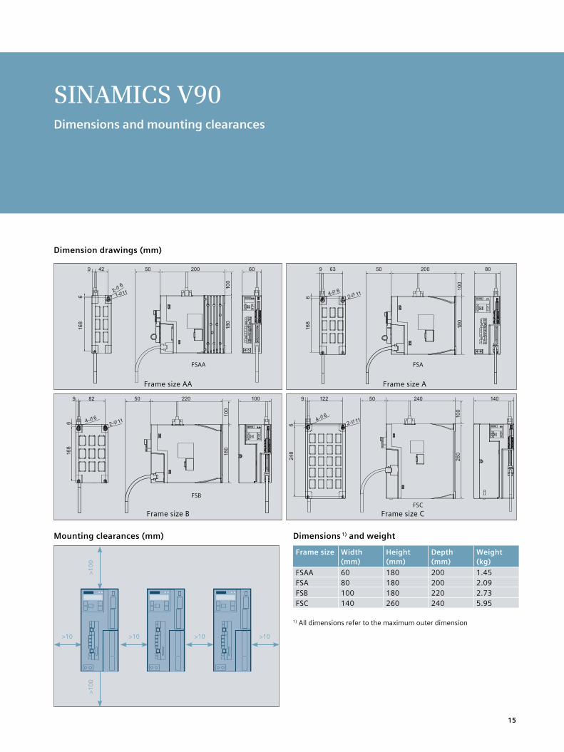
Dimension drawings (mm)
Mounting clearances (mm)
>100
>10 >10 >10 >10
>100
Motion controller
5V differential
24V single end
PLC
Motion controller
5V differential
24V single end
PLC
Motion controller
5V differential
24V single end
PLC
FSAA
FSB
FSA
FSC
SINAMICS V90Dimensions and mounting clearances
Frame size AA Frame size A
Frame size B Frame size C
Dimensions 1) and weight
Frame size Width (mm)
Height (mm)
Depth (mm)
Weight (kg)
FSAA 60 180 200 1.45FSA 80 180 200 2.09FSB 100 180 220 2.73FSC 140 260 240 5.95
1) All dimensions refer to the maximum outer dimension

16
SIMOTICS S-1FL6Technical data
Technical dataArticle number 1FL6 042−
1AF 044− 1AF
061− 1AC
062− 1AC
064− 1AC
066− 1AC
067− 1AC
090− 1AC
092− 1AC
094− 1AC
096− 1AC2
Shaft height (SH) 45 65 90Rated power (kW)1 0.40 0.75 0.75 1.00 1.50 1.75 2.00 2.50 3.50 5.00 7.00Horsepower (HP) 0.54 1.02 1.02 1.36 2.04 2.38 2.72 3.40 4.76 6.80 9.52Rated torque (Nm) 1.27 2.39 3.58 4.78 7.16 8.36 9.55 11.90 16.70 23.90 33.40Rated speed (rpm) 3000 2000 2000Maximum torque (Nm)1 3.8 7.2 10.7 14.3 21.5 25.1 28.7 35.7 50.0 70.0 90.0Maximum speed (r/min) 4000 3000 3000 2500 2000Rated current (A) 1.2 2.1 2.5 3.0 4.6 5.3 5.9 7.8 11.0 12.6 13.2Maximum current (A) 3.6 6.3 7.5 9.0 13.8 15.9 17.7 23.4 32.9 36.9 35.6Torque constant (Nm/A) 1.1 1.2 1.5 1.7 1.6 1.7 1.7 1.6 1.6 2.0 2.7Moment of inertia (10−4kg∙m2)(with brake)
2.7 (3.2)
5.2 (5.7)
8.0 (9.1)
15.3 (16.4)
15.3 (16.4)
22.6 (23.7)
29.9 (31.0)
47.4 (56.3)
69.1 (77.9)
90.8 (99.7)
134.3 (143.2)
Thermal class B (130°C) Degree of protection IP65Recommended load to motor inertia ratio
Max. 10x Max. 5x Max. 5x
Encoder types Incremental encoder TTL 2500 S/R, absolute encoder 20-bit single-turn + 12-bit multi-turnType of construction IM B5 (IM V1 and IM V3) Weight (kg)4 (with brake)
3.3 (4.6)
5.1 (6.4)
5.6 (8.6)
8.3 (11.3)
8.3 (11.3)
11.0 (14.0)
13.6 (16.6)
15.3 (21.3)
19.7 (25.7)
24.3 (30.3)
33.2 (39.1)
Operating temperature 0 ~ 40 °C (without any restrictions)Operating humidity 90% RH maximum (no condensation at 30°C) Vibration severity grade Grade ARadial runout tolerance NInstallation altitude ≤ 1000 m (without power derating); > 1000 m and up to 5000 m (with power derating)Standards
, Holding brake data3
Holding torque (Nm) 3.5 12.0 30.0Rated voltage (V) 24V DC ±10% Opening time (ms) 60 180 220Closing time (ms) 45 60 115Rated current (A) 0.9 1.5 1.9
1) The data of rated torque, rated power and maximum torque in the table above allow a tolerance of 10%, due to production tolerances.
2) For 1FL6096 motor with brake, when the ambient temperature is more than 30ºC, the power should be derated by 10%. Power derating is not required for other motors.
3) It is not permissible to use the holding brake for an emergency stop.4) Motor weight with incremental encoder

17
SIMOTICS S-1FL6 Torque-speed characteristic when connected to SINAMICS V90
1000
1
0 0
2
3
4
5
30002000 4000 5000
1FL6042-1AF6
2
0 0
4
6
8
10
12
1000 2000 3000
1FL6061-1AC6
2 0
0
468
10121416
1000 2000 3000
5
0 0
10
15
20
25
1000 2000 3000
1FL6064-1AC61FL6062-1AC6
5
0 0
10
15
20
25
30
1000 2000 3000
10
0 0
20
30
40
50
60
1000 2000 3000
1FL6092-1AC6
1FL6066-1AC6
5
0 0
10
15
20
25
30
35
1000 2000 3000
1FL6067-1AC6
5 0
0
1015202530354045
1000 2000 3000
1FL6090-1AC6
0 0
1020304050607080
1000 2000 3000
1FL6094-1AC6
0 0
102030405060708090
100
1000 2000
1FL6096-1AC6
1000
2
0 0
4
6
8
10
30002000 4000 5000
1FL6044-1AF6
B
A
B
A
B
A
B
A
B
A
B
A
B
A
B
A
B
A
B
A
B
A
Notes: A: Continuous operating area B: Short-term operating area
: Supply voltage 400V : Supply voltage 380V
Torq
ue (N
m)
Torq
ue (N
m)
Torq
ue (N
m)
Torq
ue (N
m)
Torq
ue (N
m)
Torq
ue (N
m)
Torq
ue (N
m)
Torq
ue (N
m)
Torq
ue (N
m)
Torq
ue (N
m)
Torq
ue (N
m)
Speed (rpm)
Speed (rpm)Speed (rpm)
Speed (rpm)Speed (rpm)
Speed (rpm)Speed (rpm)Speed (rpm)
Speed (rpm)Speed (rpm)Speed (rpm)

18
SIMOTICS S-1FL6Dimension drawings
Motor with incremental encoder (dimensions in mm)
Shaft Without brake With brake
height Type LC LA LZ N LR T LG D DB E QK GA F LB KB1 KB2 LB KB1 KB2 KL1 KL2 KL3 KL4
45 1FL6042 90 100 7 80 35 4 10 19 M6x16 30 25 21.5 6 154,5 93,5 - 201 140 31,5 129 92 - -
1FL6044 90 100 7 80 35 4 10 19 M6x16 30 25 21.5 6 201,5 140.5 - 248 187 31,5 129 92 - -
65 1FL6061 130 145 9 110 58 6 12 22 M8x16 50 44 25 8 148 85,5 - 202,5 140 39,5 151 115 23 22
1FL6062 130 145 9 110 58 6 12 22 M8x16 50 44 25 8 181 118.5 - 235,5 173 39,5 151 115 23 22
1FL6064 130 145 9 110 58 6 12 22 M8x16 50 44 25 8 181 118.5 - 235,5 173 39,5 151 115 23 22
1FL6066 130 145 9 110 58 6 12 22 M8x16 50 44 25 8 214 151.5 - 268,5 206 39,5 151 115 23 22
1FL6067 130 145 9 110 58 6 12 22 M8x16 50 44 25 8 247 184.5 - 301,5 239 39,5 151 115 23 22
90 1FL6090 180 200 13.5 114.3 80 3 18 35 M12x25 75 60 38 10 189,5 140 - 255 206 44,5 177 149 34 34
1FL6092 180 200 13.5 114.3 80 3 18 35 M12x25 75 60 38 10 211,5 162 - 281 232 44,5 177 149 34 34
1FL6094 180 200 13.5 114.3 80 3 18 35 M12x25 75 60 38 10 237,5 188 - 307 258 44,5 177 149 34 34
1FL6096 180 200 13.5 114.3 80 3 18 35 M12x25 75 60 38 10 289,5 240 - 359 310 44,5 177 149 34 34
With incremental encoder
Note: 1) ① Power connector, ② Incremental encoder connector, ③ Brake connector Connectors should be ordered separately, for ordering information please refer to section "Options" in this document.
2) Outline dimensions of ② incremental encoder connector ③ brake connector are the same.3) Shaft height 90 motor has M8 screws for eyebolts.
Version with feather key
Oil seal

19
Dimension drawings
Motor with absolute encoder (dimensions in mm)
Shaft Without brake With brake
height Type LC LA LZ N LR T LG D DB E QK GA F LB KB1 KB2 LB KB1 KB2 KL1 KL2 KL3 KL4
45 1FL6042 90 100 7 80 35 4 10 19 M6x16 30 25 21.5 6 157 100 - 203,5 147 31,5 129 60 - -
1FL6044 90 100 7 80 35 4 10 19 M6x16 30 25 21.5 6 204 147 - 250,5 194 31,5 129 60 - -
65 1FL6061 130 145 9 110 58 6 12 22 M8x16 50 44 25 8 151 92 - 205,5 147 39,5 151 60 - -
1FL6062 130 145 9 110 58 6 12 22 M8x16 50 44 25 8 184 125 - 238,5 180 39,5 151 60 - -
1FL6064 130 145 9 110 58 6 12 22 M8x16 50 44 25 8 184 125 - 238,5 180 39,5 151 60 - -
1FL6066 130 145 9 110 58 6 12 22 M8x16 50 44 25 8 217 158 - 271,5 213 39,5 151 60 - -
1FL6067 130 145 9 110 58 6 12 22 M8x16 50 44 25 8 250 191 - 304,5 246 39,5 151 60 - -
90 1FL6090 180 200 13.5 114.3 80 3 18 35 M12x25 75 60 38 10 197 135 - 263 201 44,5 177 60 - -
1FL6092 180 200 13.5 114.3 80 3 18 35 M12x25 75 60 38 10 223 161 - 289 227 44,5 177 60 - -
1FL6094 180 200 13.5 114.3 80 3 18 35 M12x25 75 60 38 10 249 187 - 315 253 44,5 177 60 - -
1FL6096 180 200 13.5 114.3 80 3 18 35 M12x25 75 60 38 10 301 239 - 367 305 44,5 177 60 - -
With absolute encoder
Note: 1) ① Power connector, ② Absolute encoder connector, ③ Brake connector Connectors should be ordered separately, for ordering information please refer to section "Options" in this document.
2) Outline dimensions of ② absolute encoder connector ③ brake connector are the same.3) Shaft height 90 motor has M8 screws for eyebolts.
Version with feather key
Oil seal

20
Quick release connectorHigh quality metal connector
High-quality bearings
Shaft sleeve protection
IP65 as standard for all motors
High wear-resistant oil seal material
System at a glance
Safe Torque off• Sate torque off function
SD card slot• To copy parameters
Standard mini USB• To connect a PC with
engineering tool
High quality safety connectors
Status indicator• RDY indicates the servo
ready/alarm• COM indicates
communication with PC
Integrated Operator Panel• 6 digits, 7-segment LED• 5 buttons
Braking resistor • If internal braking resistor
is not sufficient, disconnect DCP and R2, then connect DCP and R1 with an external braking resistor Small encoder connector
Control/statuse interface• 50 pins• Pulse train input• Encoder emulation pulse output• DI/DO, AI/AO
Motor holding brake• Motor holding brake can be
connected without external relay
Shield plate• Easy to attach cables and
better EMC performance
20
21
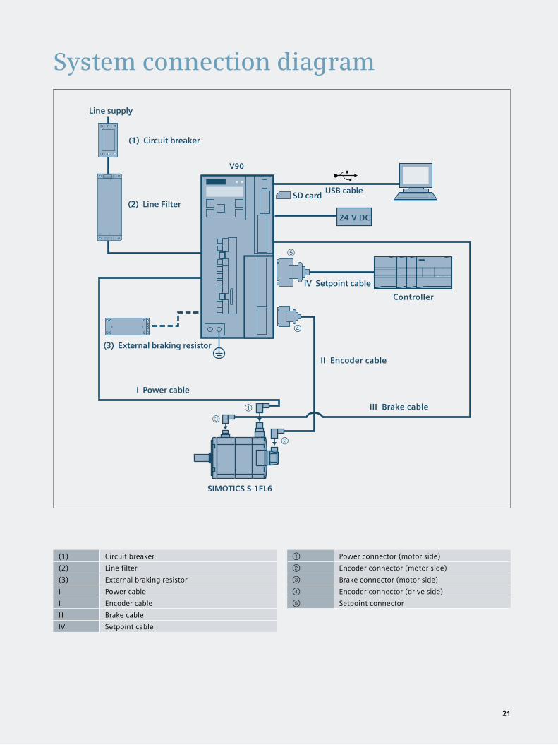
System connection diagram
(1) Circuit breaker(2) Line filter(3) External braking resistorⅠ Power cableⅡ Encoder cableⅢ Brake cableIV Setpoint cable
① Power connector (motor side)② Encoder connector (motor side)③ Brake connector (motor side)④ Encoder connector (drive side)⑤ Setpoint connector
➃
➀
➁
➂
➄
III Brake cable
Controller
II Encoder cable
IV Setpoint cable
SIMOTICS S-1FL6
I Power cable
(3) External braking resistor
(2) Line Filter
(1) Circuit breaker
Line supply
SD card USB cable
24 V DC
V90
21

22
SINAMICS V90 and SIMOTICS S-1FL6 Ordering informationSINAMICS V90 servo drive
SIMOTICS S-1FL6 servomotor
Symbol Line supply voltageE 380…480 3AC
Symbol Shaft height04 4506 6509 90
Symbol Shaft versionA Feather key, without holding brakeB Feather key, with holding brakeG Plain shaft, without holding brakeH Plain shaft, with holding brake
Symbol Encoder typesA Incremental TTL 2500 S/RL Absolute 20-bit
Symbol Rated speedC 2000 rpmF 3000 rpm
Symbol Rated torque04 2 1.27 Nm04 4 2.39 Nm06 1 3.58 Nm06 2 4.78 Nm06 4 7.16 Nm06 6 8.36 Nm06 7 9.55 Nm09 0 11.90 Nm09 2 16.70 Nm09 4 23.90 Nm09 6 33.40 Nm
6SL3210 - 5F E 17 – 0 UA0
1FL6 06 7- 1A C 61 – 0 A H 1
SIMOTICS S-1FL6 SINAMICS V90Rated Power(kW)
Rated torque(Nm)
Rated speed(rpm) Shaft height Article number Article number Frame size
0.40 1.27 3000 SH45 1FL6042 -1AF61-0 1 6SL3210-5FE10-4UA0 FSAA0.75 2.39 3000 1FL6044 -1AF61-0 1 6SL3210-5FE10-8UA0
FSA0.75 3.58 2000
SH65
1FL6061 -1AC61-0 1 6SL3210-5FE11-0UA01.00 4.78 2000 1FL6062 -1AC61-0 11.50 7.16 2000 1FL6064 -1AC61-0 1 6SL3210-5FE11-5UA0
FSB1.75 8.36 2000 1FL6066 -1AC61-0 12.00 9.55 2000 1FL6067 -1AC61-0 1 6SL3210-5FE12-0UA02.50 11.90 2000
SH90
1FL6090 -1AC61-0 13.50 16.70 2000 1FL6092 -1AC61-0 1 6SL3210-5FE13-5UA0
FSC5.00 23.90 2000 1FL6094 -1AC61-0 1 6SL3210-5FE15-0UA0 7.00 33.40 2000 1FL6096 -1AC61-0 1 6SL3210-5FE17-0UA0
Encoder typeIncremental encoder TTL 2500 S/R AAbsolute encoder 20-bit single-turn + 12-bit multi-turn L
Shaft version Feather key and holding brake
Feather key, without holding brake AFeather key, with holding brake BPlain shaft, without holding brake GPlain shaft, with holding brake H
Symbol Rated power of supported servomotor
10 - 4 0.40 kW10 - 8 0.75 kW11 - 0 1.00 kW11 - 5 1.50 kW12 - 0 2.00 kW13 - 5 3.50 kW15 - 0 5.00 kW17 - 0 7.00 kW

23
Full range of optionsSelection and ordering information
Connector and cable (between V90 servo drive and control system)Name Article No.Control/setpoint MDR 50-pin connector (packaging unit: 30 pieces) 6SL3260-2NA00-0VA0Control/setpoint cable, 1 m cable, with a connector (MDR 50-pin connector, free pins to controller side) 6SL3260-4NA00-1VB0Control/setpoint cable, 0.5 m cable, with connectors on both sides and a separate terminal block (MDR 50-pin connector, terminal block to controller side)
6SL3260-4NA00-1VA5
Recommended line-side componentV90 Article No.
Line filter1 Recommended fuse/circuit breaker Corresponding to the IEC standard
6SL3210-5FE… Rated current (A)
Article No. Standard fuse Circuit breakerCurrent (A) Article No. Article No.
10-4UA0 5 6SL3203-0BE15-0VA0 6 3NA3801-6 3RV2021-1DA1010-8UA0 5 6 3NA3801-6 3RV2021-1EA1011-0UA0 5 10 3NA3803-6 3RV2021-1FA1011-5UA0 12 6SL3203-0BE21-2VA0 16 3NA3805-6 3RV2021-1JA1012-0UA0 12 16 3NA3805-6 3RV2021-4AA1013-5UA0 20 6SL3203-0BE22-0VA0 25 3NA3807-6 3RV2021-4BA1015-0UA0 20 25 3NA3807-6 3RV2021-4DA1017-0UA0 20 25 3NA3810-6 3RV2021-4DA10
External braking resistor2
Frame size Resistance (Ω)
Max. Power (kW)
Rated power (W)
Max. energy (KJ)
FSAA 533 1.2 30 2.4FSA 160 4 100 8.0FSB 70 9.1 229 18FSC 27 23.7 1185 190
1 With one of the recommended line filter, EN61008-3 category C2 can be reached in combination with SINAMICS V90
2 When the internal braking resistor is not sufficient, select a standard braking resistor according to the table
Spare partsReplacement fan Article No.FSB 6SL3200-0WF00-0AA0FSC 6SL3200-0WF01-0AA0
AccessoriesSINAMICS SD card 6SL3054-4AG00-2AA0Training case SINAMICS V90
6AG1067-3AA00-0AB0
Name Used for Article No.*6FX2003-...
Power connector Motor side 0LL11Absolute encoder connector
Motor side 0DB11
Incremental encoder connector
Motor side 0SL11
Brake connector Motor side 0LL51Encoder connector Drive side 0SB14 *Connector, packaging unit 30 pieces
Name Article No.6FX3002-…
No. of cores x cross-section (mm2)
Length(m)
MOTION-CONNECT MC300 power cable for FSAA and FSA
5CL01-1AD0 4 x 1.5 35CL01-1AF0 4 x 1.5 55CL01-1AH0 4 x 1.5 75CL01-1BA0 4 x 1.5 105CL01-1CA0 4 x 1.5 20
MOTION-CONNECT MC300 power cable for FSB and FSC
5CL11-1AD0 4 x 2.5 35CL11-1AF0 4 x 2.5 55CL11-1AH0 4 x 2.5 75CL11-1BA0 4 x 2.5 105CL11-1CA0 4 x 2.5 20
MOTION-CONNECT MC300 encoder cable (for absolute encoder)
2DB10-1AD0 3 x 2 x 0.22 + 2 x 2 x 0.25 32DB10-1AF0 3 x 2 x 0.22 + 2 x 2 x 0.25 52DB10-1AH0 3 x 2 x 0.22 + 2 x 2 x 0.25 72DB10-1BA0 3 x 2 x 0.22 + 2 x 2 x 0.25 102DB10-1CA0 3 x 2 x 0.22 + 2 x 2 x 0.25 20
MOTION-CONNECT MC300 encoder cable (for incremental en-coder)
2CT10-1AD0 3 x 2 x 0.22 + 2 x 2 x 0.25 32CT10-1AF0 3 x 2 x 0.22 + 2 x 2 x 0.25 52CT10-1AH0 3 x 2 x 0.22 + 2 x 2 x 0.25 72CT10-1BA0 3 x 2 x 0.22 + 2 x 2 x 0.25 102CT10-1CA0 3 x 2 x 0.22 + 2 x 2 x 0.25 20
MOTION-CONNECT MC300 brake cable (for holding brake)
5BL02-1AD0 2 x 0.75 35BL02-1AF0 2 x 0.75 55BL02-1AH0 2 x 0.75 75BL02-1BA0 2 x 0.75 105BL02-1CA0 2 x 0.75 20
MOTION-CONNECT 300 cables and connectors (between SINAMICS V90 servo drive and SIMOTICS S-1FL6 motor)

Subject to change without prior notice Article No.: E20001-A280-P670-V1-7600 DISPO 21500 WÜ/66744 V6.MKSINA.WES WS 04157.0 Printed in Germany © Siemens AG 2015
The information provided in this brochure con-tains merely general descriptions or characteris-tics of performance which in case of actual use do not always apply as described or which may change as a result of further development of the products. An obligation to provide the respec-tive characteristics shall only exist if expressly agreed in the terms of contract. All product designations may be trademarks or product names of Siemens AG or supplier com-panies whose use by third parties for their own purposes could violate the rights of the owners
Siemens provides products and solutions with industrial security functions that support the secure operation of plants, solutions, machines, equipment and/or networks. They are important components in a holistic industrial security concept. With this in mind, Siemens’ products and solutions undergo continuous development. Siemens recommends strongly that you regu-larly check for product updates. For the secure operation of Siemens products and solutions, it is necessary to take suitable preventive action (e.g. cell protection concept) and integrate each component into a holistic, state-of-the-art industrial security concept. Third-party products that may be in use should also be considered. For more information about industrial security, visit http://www.siemens.com/industrialsecurity. To stay informed about product updates as they occur, sign up for a product-specific newsletter. For more information, visit http://support.automation.siemens.com
Follow us on: twitter.com/siemensindustry youtube.com/siemens
Siemens AG Digital Factory P.O. Box 31 80 91050 Erlangen GERMANY
Find out more:
siemens.com/ids
Experience how Integrated Drive Systems can boost the competitiveness of production plants and entire companies in every sector.
The advantages of Integrated Drive Systems at a glance