sinamics v90, simotics s-1fl6
TRANSCRIPT

SINAMICS V90, SIMOTICS S-1FL6
___________________
___________________
___________________
___________________
___________________
___________________
___________________
___________________
___________________
___________________
___________________
___________________
___________________
SINAMICS/SIMOTICS
SINAMICS V90, SIMOTICS S-1FL6
Operating Instructions
04/2014 6SL3298-0AV60-0BP0
Preface
Safety instructions 1
General information 2
Mounting 3
Connecting 4
Commissioning 5
Basic operator panel (BOP) 6
Control functions 7
Safety Integrated function 8
Tuning 9
Parameters 10
Diagnostics 11
Appendix A
Siemens AG Industry Sector Postfach 48 48 90026 NÜRNBERG GERMANY
Order number: 6SL3298-0AV60-0BP0 Ⓟ 04/2014 Subject to change
Copyright © Siemens AG 2013 - 2014. All rights reserved
Legal information Warning notice system
This manual contains notices you have to observe in order to ensure your personal safety, as well as to prevent damage to property. The notices referring to your personal safety are highlighted in the manual by a safety alert symbol, notices referring only to property damage have no safety alert symbol. These notices shown below are graded according to the degree of danger.
DANGER indicates that death or severe personal injury will result if proper precautions are not taken.
WARNING indicates that death or severe personal injury may result if proper precautions are not taken.
CAUTION indicates that minor personal injury can result if proper precautions are not taken.
NOTICE indicates that property damage can result if proper precautions are not taken.
If more than one degree of danger is present, the warning notice representing the highest degree of danger will be used. A notice warning of injury to persons with a safety alert symbol may also include a warning relating to property damage.
Qualified Personnel The product/system described in this documentation may be operated only by personnel qualified for the specific task in accordance with the relevant documentation, in particular its warning notices and safety instructions. Qualified personnel are those who, based on their training and experience, are capable of identifying risks and avoiding potential hazards when working with these products/systems.
Proper use of Siemens products Note the following:
WARNING Siemens products may only be used for the applications described in the catalog and in the relevant technical documentation. If products and components from other manufacturers are used, these must be recommended or approved by Siemens. Proper transport, storage, installation, assembly, commissioning, operation and maintenance are required to ensure that the products operate safely and without any problems. The permissible ambient conditions must be complied with. The information in the relevant documentation must be observed.
Trademarks All names identified by ® are registered trademarks of Siemens AG. The remaining trademarks in this publication may be trademarks whose use by third parties for their own purposes could violate the rights of the owner.
Disclaimer of Liability We have reviewed the contents of this publication to ensure consistency with the hardware and software described. Since variance cannot be precluded entirely, we cannot guarantee full consistency. However, the information in this publication is reviewed regularly and any necessary corrections are included in subsequent editions.

SINAMICS V90, SIMOTICS S-1FL6 Operating Instructions, 04/2014, 6SL3298-0AV60-0BP0 3
Preface
Documentation components Document Content Operating Instructions (this manual) Getting Started Describes how to install, connect, operate, and perform
basic commissioning of the SINAMICS V90 servo system. Fan Replacement Guide Describes how to replace fans for the SINAMICS V90 servo
drives. SIMOTICS S-1FL6 Servo Motors Installation Guide Describes how to install the SMOTICS S-1FL6 servo motor
and relevant safety notices.
Target group This manual provides information about the SINAMICS V90 servo system for planners, operators, mechanical engineers, electrical engineers, commissioning engineers, and service engineers.
Technical support Country Hotline China +86 400 810 4288 Germany +49 (0) 911 895 7222 Italy +39 (02) 24362000 India +91 22 2760 0150 Turkey +90 (216) 4440747 Further service contact information: Support contacts (http://support.automation.siemens.com/WW/view/en/16604999)

Preface
SINAMICS V90, SIMOTICS S-1FL6 4 Operating Instructions, 04/2014, 6SL3298-0AV60-0BP0

SINAMICS V90, SIMOTICS S-1FL6 Operating Instructions, 04/2014, 6SL3298-0AV60-0BP0 5
Table of contents
Preface ................................................................................................................................................... 3
1 Safety instructions ................................................................................................................................. 11
1.1 General safety instructions .......................................................................................................... 11
1.2 Safety instructions for electromagnetic fields (EMF) ................................................................... 14
1.3 Handling electrostatic sensitive devices (ESD) ........................................................................... 14
1.4 Residual risks of power drive systems ......................................................................................... 14
1.5 Additional safety instructions ....................................................................................................... 16
2 General information .............................................................................................................................. 23
2.1 Deliverables ................................................................................................................................. 23 2.1.1 Drive components ........................................................................................................................ 23 2.1.2 Motor components ....................................................................................................................... 25
2.2 Device combination ...................................................................................................................... 27
2.3 Product overview.......................................................................................................................... 28
2.4 System configuration ................................................................................................................... 29
2.5 Accessories .................................................................................................................................. 31
2.6 Function list .................................................................................................................................. 35
2.7 Technical data .............................................................................................................................. 37 2.7.1 Technical data - servo drives ....................................................................................................... 37 2.7.2 Technical data - servo motors ...................................................................................................... 39 2.7.3 Technical data - cables ................................................................................................................ 44
3 Mounting ............................................................................................................................................... 45
3.1 Mounting the drive ....................................................................................................................... 45 3.1.1 Mounting orientation and clearance ............................................................................................. 45 3.1.2 Drill patterns and outline dimensions ........................................................................................... 46 3.1.3 Mounting the drive ....................................................................................................................... 48
3.2 Mounting the motor ...................................................................................................................... 48 3.2.1 Mounting orientation and dimensions .......................................................................................... 49 3.2.2 Mounting the motor ...................................................................................................................... 53
4 Connecting ........................................................................................................................................... 55
4.1 System connection ....................................................................................................................... 55
4.2 Main circuit wirings ....................................................................................................................... 57 4.2.1 Line supply - L1, L2, L3 ................................................................................................................ 57 4.2.2 Motor power - U, V, W ................................................................................................................. 58
4.3 Control/Status interface - X8 ........................................................................................................ 59 4.3.1 Digital inputs/outputs (DIs/DOs) ................................................................................................... 61 4.3.1.1 DIs ................................................................................................................................................ 62

Table of contents
SINAMICS V90, SIMOTICS S-1FL6 6 Operating Instructions, 04/2014, 6SL3298-0AV60-0BP0
4.3.1.2 DOs ............................................................................................................................................. 66 4.3.2 Pulse train inputs/encoder outputs (PTIs/PTOs)......................................................................... 69 4.3.2.1 PTIs ............................................................................................................................................. 69 4.3.2.2 PTOs ........................................................................................................................................... 70 4.3.3 Analog inputs/outputs (AIs/AOs) ................................................................................................. 70 4.3.3.1 AIs ............................................................................................................................................... 70 4.3.3.2 AOs ............................................................................................................................................. 71 4.3.4 Standard application wirings (factory setting) ............................................................................. 73 4.3.4.1 Pulse train input position control (PTI) ........................................................................................ 73 4.3.4.2 Internal position control (IPos) .................................................................................................... 74 4.3.4.3 Speed control (S) ........................................................................................................................ 75 4.3.4.4 Torque control (T) ....................................................................................................................... 76 4.3.5 Connection examples with PLCs ................................................................................................ 77 4.3.5.1 SIMATIC S7-200 SMART ........................................................................................................... 78 4.3.5.2 SIMATIC S7-200 ......................................................................................................................... 82 4.3.5.3 SIMATIC S7-1200 ....................................................................................................................... 86
4.4 24V power supply/STO - X6........................................................................................................ 90
4.5 Encoder interface - X9 ................................................................................................................ 91
4.6 External braking resistor - DCP, R1 ............................................................................................ 94
4.7 Motor holding brake - X7 ............................................................................................................. 94
4.8 RS485 interface - X12 ................................................................................................................. 95
5 Commissioning ..................................................................................................................................... 97
5.1 Initial commissioning in JOG mode ............................................................................................. 98
5.2 Commissioning in pulse train position control mode (PTI) ........................................................ 100
5.3 Commissioning in internal position control mode (IPos) ........................................................... 101
5.4 Commissioning in speed control mode (S) ............................................................................... 103
5.5 Commissioning in torque control mode (T) ............................................................................... 105
6 Basic operator panel (BOP) ................................................................................................................. 107
6.1 BOP overview ........................................................................................................................... 107 6.1.1 BOP display .............................................................................................................................. 107 6.1.2 Control buttons .......................................................................................................................... 110
6.2 Parameter structure .................................................................................................................. 111
6.3 Actual status display ................................................................................................................. 112
6.4 Basic operations ........................................................................................................................ 113 6.4.1 Editing parameters .................................................................................................................... 113 6.4.2 Viewing parameters .................................................................................................................. 116 6.4.3 Searching parameters in "P ALL" menu ................................................................................... 116
6.5 Auxiliary functions ..................................................................................................................... 117 6.5.1 Jog ............................................................................................................................................. 118 6.5.2 Saving parameters (RAM to ROM) ........................................................................................... 119 6.5.3 Setting parameters to default .................................................................................................... 119 6.5.4 Transferring data (drive to SD) ................................................................................................. 120 6.5.5 Transferring data (SD to drive) ................................................................................................. 121 6.5.6 Updating firmware ..................................................................................................................... 122

Table of contents
SINAMICS V90, SIMOTICS S-1FL6 Operating Instructions, 04/2014, 6SL3298-0AV60-0BP0 7
6.5.7 Adjusting AI offsets .................................................................................................................... 122 6.5.8 Adjusting an absolute encoder ................................................................................................... 124
7 Control functions ................................................................................................................................. 125
7.1 Compound controls .................................................................................................................... 125
7.2 General functions ....................................................................................................................... 126 7.2.1 Servo ON ................................................................................................................................... 126 7.2.2 Direction of motor rotation .......................................................................................................... 127 7.2.3 Over-travel ................................................................................................................................. 128 7.2.4 Motor holding brake ................................................................................................................... 130 7.2.5 Stopping method at servo OFF .................................................................................................. 132
7.3 Pulse train input position control (PTI) ....................................................................................... 133 7.3.1 Selecting a setpoint pulse train input channel ........................................................................... 133 7.3.2 Selecting a setpoint pulse train input form ................................................................................. 133 7.3.3 In position (INP) ......................................................................................................................... 134 7.3.4 Smoothing function .................................................................................................................... 135 7.3.5 Electronic gear ratio ................................................................................................................... 136 7.3.6 Inhibiting pulse train input setpoint (P-TRG) .............................................................................. 139 7.3.7 Speed limit ................................................................................................................................. 140 7.3.8 Torque limit ................................................................................................................................ 141 7.3.9 Clearing droop pulses (CLR) ..................................................................................................... 144 7.3.10 Referencing (only for absolute encoder) .................................................................................... 144 7.3.11 PTO function .............................................................................................................................. 145
7.4 Internal position control (IPos) ................................................................................................... 146 7.4.1 Setting mechanical system ........................................................................................................ 146 7.4.2 Setting fixed position setpoint .................................................................................................... 147 7.4.3 Selecting a positioning mode - absolute/incremental ................................................................ 149 7.4.4 Configuring linear/modular axis ................................................................................................. 150 7.4.5 Backlash compensation ............................................................................................................. 150 7.4.6 Referencing ................................................................................................................................ 151 7.4.7 Software position limit ................................................................................................................ 159 7.4.8 Speed limit ................................................................................................................................. 160 7.4.9 Torque limit ................................................................................................................................ 160 7.4.10 Selecting a fixed position setpoint and starting positioning ....................................................... 160
7.5 Speed control (S) ....................................................................................................................... 162 7.5.1 Configuring speed setpoint ........................................................................................................ 162 7.5.1.1 Speed control with external analog speed setpoint ................................................................... 163 7.5.1.2 Speed control with fixed speed setpoint .................................................................................... 164 7.5.2 Direction and stop ...................................................................................................................... 165 7.5.3 Speed limit ................................................................................................................................. 165 7.5.4 Torque limit ................................................................................................................................ 165 7.5.5 Zero speed clamp ...................................................................................................................... 166 7.5.6 Ramp-function generator ........................................................................................................... 167
7.6 Torque control (T) ...................................................................................................................... 168 7.6.1 300% overload capacity ............................................................................................................. 168 7.6.2 Torque setpoint .......................................................................................................................... 169 7.6.2.1 Torque control with external analog torque setpoint .................................................................. 170 7.6.2.2 Torque control with fixed torque setpoint ................................................................................... 171 7.6.3 Direction and stop ...................................................................................................................... 171 7.6.4 Speed limit ................................................................................................................................. 172

Table of contents
SINAMICS V90, SIMOTICS S-1FL6 8 Operating Instructions, 04/2014, 6SL3298-0AV60-0BP0
7.7 Absolute position system .......................................................................................................... 172 7.7.1 USS communication telegram .................................................................................................. 172 7.7.2 Transmitting sequence for the absolute position data .............................................................. 173
8 Safety Integrated function .................................................................................................................... 175
8.1 Standards and regulations ........................................................................................................ 175 8.1.1 General information ................................................................................................................... 175 8.1.1.1 Aims .......................................................................................................................................... 175 8.1.1.2 Functional safety ....................................................................................................................... 175 8.1.2 Safety of machinery in Europe .................................................................................................. 176 8.1.2.1 Machinery Directive ................................................................................................................... 176 8.1.2.2 Harmonized European Standards ............................................................................................. 176 8.1.2.3 Standards for implementing safety-related controllers ............................................................. 178 8.1.2.4 DIN EN ISO 13849-1 (replaces EN 954-1) ............................................................................... 179 8.1.2.5 EN 62061 .................................................................................................................................. 180 8.1.2.6 Series of standards EN 61508 (VDE 0803) .............................................................................. 181 8.1.2.7 Risk analysis/assessment ......................................................................................................... 182 8.1.2.8 Risk reduction ........................................................................................................................... 183 8.1.2.9 Residual risk .............................................................................................................................. 184 8.1.3 Machine safety in the USA ........................................................................................................ 184 8.1.3.1 Minimum requirements of the OSHA ........................................................................................ 184 8.1.3.2 NRTL listing ............................................................................................................................... 185 8.1.3.3 NFPA 79 .................................................................................................................................... 185 8.1.3.4 ANSI B11................................................................................................................................... 186 8.1.4 Machine safety in Japan ........................................................................................................... 187 8.1.5 Equipment regulations .............................................................................................................. 187
8.2 General information about SINAMICS Safety Integrated ......................................................... 187
8.3 System features ........................................................................................................................ 188 8.3.1 Certification ............................................................................................................................... 188 8.3.2 Safety instructions ..................................................................................................................... 188 8.3.3 Probability of failure of the safety function (PHF value) ............................................................ 190 8.3.4 Response time .......................................................................................................................... 190 8.3.5 Residual risk .............................................................................................................................. 190
8.4 Safety Integrated basic functions .............................................................................................. 191 8.4.1 Safe Torque Off (STO) .............................................................................................................. 191 8.4.2 Forced dormant error detection................................................................................................. 193
9 Tuning ................................................................................................................................................. 195
9.1 Controller overview ................................................................................................................... 195
9.2 First time commissioning mode................................................................................................. 197 9.2.1 Basic tuning procedure ............................................................................................................. 198 9.2.2 Configuration of dynamic factor ................................................................................................ 198
9.3 Real-time auto tuning ................................................................................................................ 200
9.4 Manual tuning ............................................................................................................................ 201
9.5 Resonance suppression ............................................................................................................ 203
9.6 Gain switching ........................................................................................................................... 206 9.6.1 Gain switching using an external digital input signal (G-CHANGE).......................................... 207 9.6.2 Gain switching using position deviation .................................................................................... 208

Table of contents
SINAMICS V90, SIMOTICS S-1FL6 Operating Instructions, 04/2014, 6SL3298-0AV60-0BP0 9
9.6.3 Gain switching using position setpoint frequency ...................................................................... 209 9.6.4 Gain switching using actual speed............................................................................................. 210
9.7 PI/P switching ............................................................................................................................. 210 9.7.1 PI/P switching using torque setpoint .......................................................................................... 212 9.7.2 PI/P switching using an external digital input signal (G-CHANGE) ........................................... 213 9.7.3 PI/P switching using speed setpoint .......................................................................................... 214 9.7.4 PI/P switching using acceleration setpoint ................................................................................. 214 9.7.5 PI/P switching using pulse deviation .......................................................................................... 215
10 Parameters ......................................................................................................................................... 217
10.1 Overview .................................................................................................................................... 217
10.2 Parameter list ............................................................................................................................. 218
11 Diagnostics ......................................................................................................................................... 249
11.1 Overview .................................................................................................................................... 249
11.2 List of faults and alarms ............................................................................................................. 253
A Appendix............................................................................................................................................. 269
A.1 Order numbers ........................................................................................................................... 269
A.2 Assembly of cable connectors on the motor side ...................................................................... 272
A.3 Assembly of cable terminals on the drive side ........................................................................... 274
A.4 Motor selection ........................................................................................................................... 276 A.4.1 Selection procedure ................................................................................................................... 276 A.4.2 Parameter description ................................................................................................................ 277 A.4.3 Selection examples .................................................................................................................... 279
A.5 Replacing fans ........................................................................................................................... 280
Index................................................................................................................................................... 283

Table of contents
SINAMICS V90, SIMOTICS S-1FL6 10 Operating Instructions, 04/2014, 6SL3298-0AV60-0BP0

SINAMICS V90, SIMOTICS S-1FL6 Operating Instructions, 04/2014, 6SL3298-0AV60-0BP0 11
Safety instructions 1 1.1 General safety instructions
DANGER
Danger to life when live parts are touched
Death or serious injury can result when live parts are touched. • Only work on electrical devices when you are qualified for this job. • Always observe the country-specific safety rules.
Generally, six steps apply when establishing safety: 1. Prepare for shutdown and notify all those who will be affected by the procedure. 2. Disconnect the machine from the supply.
– Switch off the machine. – Wait until the discharge time specified on the warning labels has elapsed. – Check that it really is in a no-voltage condition, from phase conductor to phase
conductor and phase conductor to protective conductor. – Check whether the existing auxiliary supply circuits are de-energized. – Ensure that the motors cannot move.
3. Identify all other hazardous energy sources, e.g. compressed air, hydraulic systems, water.
4. Isolate or neutralize all hazardous energy sources, e.g. by closing switches, grounding or short-circuiting or closing valves.
5. Secure the energy sources against switching on again. 6. Make sure that the machine is completely locked ... and that you have the right
machine. After you have completed the work, restore the operational readiness in the inverse sequence.
WARNING
Danger to life through a hazardous voltage when connecting an unsuitable power supply
Death or serious injury can result when live parts are touched in the event of a fault. • Only use power supplies that provide SELV (Safety Extra Low Voltage) or PELV-
(Protective Extra Low Voltage) output voltages for all connections and terminals of the electronics modules.

Safety instructions 1.1 General safety instructions
SINAMICS V90, SIMOTICS S-1FL6 12 Operating Instructions, 04/2014, 6SL3298-0AV60-0BP0
WARNING
Danger to life when live parts are touched on damaged devices
Improper handling of devices can cause damage.
Hazardous voltages can be present at the housing or exposed components on damaged devices. • Ensure compliance with the limit values specified in the technical data during transport,
storage and operation. • Do not use any damaged devices. • Protect the components against conductive pollution, e.g., by installing them in a control
cabinet with IP54 degree of protection according to IEC 60529 or NEMA 12. Provided conductive pollution can be prevented at the installation site, the degree of protection for the cabinet can be decreased accordingly.
WARNING
Danger of fire spreading due to inadequate housing
Fire and smoke development can cause severe personal injury or material damage. • Install devices without a protective housing in a metal control cabinet (or protect the
device by another equivalent measure) in such a way that contact with fire inside and outside the device is prevented.
• Additionally, select the installation site so that an uncontrolled spreading of smoke can be avoided in the case of a fire.
• Ensure that smoke can escape via designated paths.
WARNING
Danger to life through unexpected movement of machines when using mobile wireless devices or mobile phones
Using mobile wireless devices or mobile phones with a transmitter power > 1 W closer than approx. 2 m to the components may cause the devices to malfunction and influence the functional safety of machines, therefore putting people at risk or causing material damage. • Switch the wireless devices or mobile phones off in the immediate vicinity of the
components.
WARNING
Fire hazard for the motor due to overload of the insulation
There is a greater load on the motor insulation through a ground fault in an IT system. A possible result is the failure of the insulation with a risk for personnel through smoke development and fire. • Use a monitoring device that signals an insulation fault. • Correct the fault as quickly as possible so the motor insulation is not overloaded.

Safety instructions 1.1 General safety instructions
SINAMICS V90, SIMOTICS S-1FL6 Operating Instructions, 04/2014, 6SL3298-0AV60-0BP0 13
WARNING
Fire hazard due to overheating because of inadequate ventilation clearances
Inadequate ventilation clearances can cause overheating with a risk for personnel through smoke development and fire. This can also result in increased downtime and reduced service lives for devices / systems. • Ensure compliance with the specified minimum clearance as ventilation clearance for
the respective component. They can be found in the dimension drawings or in the "Product-specific safety instructions" at the start of the respective section.
WARNING
Danger to life through electric shock due to unconnected cable shields
Hazardous touch voltages can occur through capacitive cross-coupling due to unconnected cable shields. • Connect cable shields and unused conductors of power cables (e.g., brake conductors)
at least on one side to the grounded housing potential.
WARNING
Danger to life when safety functions are inactive
Safety functions that are inactive or that have not been adjusted accordingly can cause operational faults on machines that could lead to serious injury or death. • Observe the information in the appropriate product documentation before
commissioning. • Carry out a safety inspection for functions relevant to safety on the entire system,
including all safety-related components. • Ensure that the safety functions used in your drives and automation tasks are adjusted
and activated through appropriate parameterizing. • Run a function test. • Only put your plant into live operation once you have guaranteed that the functions
relevant to safety are running correctly.
Note Important safety notices for safety functions
If you want to use safety functions, you must observe the safety notices in the safety manuals.

Safety instructions 1.2 Safety instructions for electromagnetic fields (EMF)
SINAMICS V90, SIMOTICS S-1FL6 14 Operating Instructions, 04/2014, 6SL3298-0AV60-0BP0
1.2 Safety instructions for electromagnetic fields (EMF)
WARNING
Danger to life from electromagnetic fields
Electromagnetic fields (EMF) are generated by the operation of electrical power equipment such as transformers, converters or motors.
People with pacemakers or implants are at a special risk in the immediate vicinity of these devices/systems. • Keep a distance of at least 2 m.
1.3 Handling electrostatic sensitive devices (ESD) Electrostatic sensitive devices (ESD) are individual components, integrated circuits, modules or devices that may be damaged by either electric fields or electrostatic discharge.
NOTICE
Damage through electric fields or electrostatic discharge
Electric fields or electrostatic discharge can cause malfunctions through damaged individual components, integrated circuits, modules or devices. • Only pack, store, transport and send electronic components, modules or devices in their
original packaging or in other suitable materials, e.g conductive foam rubber of aluminum foil.
• Only touch components, modules and devices when you are grounded by one of the following methods: – Wearing an ESD wrist strap – Wearing ESD shoes or ESD grounding straps in ESD areas with conductive flooring
• Only place electronic components, modules or devices on conductive surfaces (table with ESD surface, conductive ESD foam, ESD packaging, ESD transport container).
1.4 Residual risks of power drive systems
Residual risks of power drive systems The control and drive components of a drive system are approved for industrial and commercial use in industrial line supplies. Their use in public line supplies requires a different configuration and/or additional measures.

Safety instructions 1.4 Residual risks of power drive systems
SINAMICS V90, SIMOTICS S-1FL6 Operating Instructions, 04/2014, 6SL3298-0AV60-0BP0 15
These components may only be operated in closed housings or in higher-level control cabinets with protective covers that are closed, and when all of the protective devices are used.
These components may only be handled by qualified and trained technical personnel who are knowledgeable and observe all of the safety instructions on the components and in the associated technical user documentation.
When assessing the machine's risk in accordance with the respective local regulations (e.g., EC Machinery Directive), the machine manufacturer must take into account the following residual risks emanating from the control and drive components of a drive system:
1. Unintentional movements of driven machine components during commissioning, operation, maintenance, and repairs caused by, for example:
– Hardware defects and/or software errors in the sensors, controllers, actuators, and connection technology
– Response times of the controller and drive
– Operating and/or surrounding conditions outside of the specification
– Condensation / conductive contamination
– Parameterization, programming, cabling, and installation errors
– Use of radio devices / cellular phones in the immediate vicinity of the controller
– External influences / damage
2. In the event of a fault, exceptionally high temperatures, including an open fire, as well as emissions of light, noise, particles, gases, etc. can occur inside and outside the inverter, e.g.:
– Component malfunctions
– Software errors
– Operating and/or surrounding conditions outside of the specification
– External influences / damage
Inverters of the Open Type / IP20 degree of protection must be installed in a metal control cabinet (or protected by another equivalent measure) such that the contact with fire inside and outside the inverter is not possible.
3. Hazardous shock voltages caused by, for example:
– Component malfunctions
– Influence of electrostatic charging
– Induction of voltages in moving motors
– Operating and/or surrounding conditions outside of the specification
– Condensation / conductive contamination
– External influences / damage

Safety instructions 1.5 Additional safety instructions
SINAMICS V90, SIMOTICS S-1FL6 16 Operating Instructions, 04/2014, 6SL3298-0AV60-0BP0
4. Electrical, magnetic and electromagnetic fields generated in operation that can pose a risk to people with a pacemaker, implants or metal replacement joints, etc. if they are too close.
5. Release of environmental pollutants or emissions as a result of improper operation of the system and/or failure to dispose of components safely and correctly.
Note
The components must be protected against conductive contamination (e.g. by installing them in a control cabinet with degree of protection IP54 according to IEC 60529 or NEMA 12).
Assuming that conductive contamination at the installation site can definitely be excluded, a lower degree of cabinet protection may be permitted.
For more information about residual risks of the components in a drive system, see the relevant sections in the technical user documentation.
1.5 Additional safety instructions
Delivery check
Note Intact deliverables
Deliverables received must be intact. It's not permissible to put a damaged unit into use.
Transport and storage
NOTICE
Property loss
Notify Siemens service personnel immediately of any damage discovered after delivery. If the equipment is put into storage, keep it in a dry, dust-free, and low-vibration environment. The storage temperature ranges from -40 °C to +70 °C.
Otherwise you will suffer property loss.

Safety instructions 1.5 Additional safety instructions
SINAMICS V90, SIMOTICS S-1FL6 Operating Instructions, 04/2014, 6SL3298-0AV60-0BP0 17
Mechanical installation
WARNING
Death or severe personal injury from harsh installation environment
A harsh installation environment will jeopardize personal safety and equipment. Therefore, • Do not install the drive and the motor in an area subject to inflammables or
combustibles, water or corrosion hazards. • Do not install the drive and the motor in an area where it is likely to be exposed to
constant vibrations or physical shocks. • Do not keep the drive exposed to strong electro-magnetic interference. • Make sure that no foreign body (e.g., chips of wood or metal, dust, paper, etc.) can be
seen inside the drive or on the heat sink of the drive. • Make sure that the drive is installed in an electrical cabinet with an adequate degree of
protection.
Note Mounting clearance
To guarantee good heat dissipation and ease of cabling, keep sufficient clearance between drives, one drive and another device/inner wall of the cabinet.
Note Screw tightening
Make sure you fix the screw to the terminal door of the drive after you have completed the installation work.
Electrical installation
DANGER
Death or severe personal injury from electrical shock
The earth leakage current for the drive can be greater than AC 3.5 mA, which may cause death or severe personal injury due to electrical shock.
A fixed earth connection is required to eliminate the dangerous leakage current. In addition, the minimum size of the protective earth conductor shall comply with the local safety regulations for high leakage current equipment.

Safety instructions 1.5 Additional safety instructions
SINAMICS V90, SIMOTICS S-1FL6 18 Operating Instructions, 04/2014, 6SL3298-0AV60-0BP0
WARNING
Personal injury and damage to property from improper connections
Improper connections have high risks of electrical shock and short circuit, which will jeopardize personal safety and equipment. • The drive must be directly connected with the motor. It is not permissible to connect a
capacitor, inductor or filter between them. • Make sure that all connections are correct and reliable, the drive and the motor are well
grounded. • The line supply voltage must be within the allowable range (refer to the drive rating
plate). Never connect the line supply cable to the motor terminals U, V, W or connect the motor power cable to the line input terminals L1, L2, L3.
• Never wire up the U, V, W terminals in an interchanged phase sequence. • If the CE marking for cables is mandatory in some cases, the motor power cable, line
supply cable and brake cable used must all be shielded cables. • For terminal box connection, make sure that the clearances in air between non-insulated
live parts are at least 5.5 mm. • Route signal cables and power cables separately in different cable conduits. The signal
cables shall be at least 10 cm away from the power cables. • Cables connected may not come into contact with rotating mechanical parts.
CAUTION
Personal injury and damage to property from inadequate protection
Inadequate protection may cause minor personal injury or damage to property. • The drive must have been disconnected from the power supply for at least five minutes
before you perform any wiring to it. • Check that the equipment is dead! • Make sure that the drive and the motor are properly grounded. • Route a second PE conductor with the cross section of the supply system lead in
parallel to the protective earth via separate terminals or use a copper protective earth conductor with a cross section of 10 mm2.
• Terminals for equipotential bondings that exist in addition to terminals for PE conductors must not be used for looping-through the PE conductors.
• To ensure protective separation, an isolating transformer must be used for the 380 V AC line supply system.
NOTICE
Damage to property from incorrect input voltage
Incorrect input voltage will cause severe damage to the drive.
It is recommended that the actual input voltage should not be greater than 110% of the rated voltage or smaller than 75%.

Safety instructions 1.5 Additional safety instructions
SINAMICS V90, SIMOTICS S-1FL6 Operating Instructions, 04/2014, 6SL3298-0AV60-0BP0 19
Note STO wiring
The safe torque off (STO) function can stop a motor using safety relays without involving any upper level control. It is disabled in the factory configuration by short-circuiting the STO terminals. The safety function of the servo drive is SIL 2 (EN61800-5-2). Connect the STO terminals as the actual requirements.
Commissioning/Operation
CAUTION
Burns from hot surface
The operating temperature of drive base-plate and heat sink is higher than 65 °C, and the surface temperature of the motor may reach up to 80 °C. The hot surface may burn your hands.
Do not touch the motor or the heat sink of the drive during operation or within a certain period since power disconnection.
NOTICE
Shortening the service life of motor brake
The motor brake is used for holding purpose only. Frequent emergency stops with the motor brake will shorten its service life.
Unless absolutely necessary, do not apply the motor brake as an emergency stop or deceleration mechanism.
NOTICE
Damage to the equipment from frequent power-on/off
Frequent power-on/off will cause damage to the drive.
Do not switch on/off the power frequently.
Note Voltage requirement
Before switching the power on, make sure that the drive system has been reliably installed and connected, and the line supply voltage is within the allowable range.
Note Drive functioning interfered by use of radio devices
Some environmental factors may result in power derating, e.g. altitude and surrounding temperature. In this case, the drive cannot work normally.
Environmental factors must be taken into account during commissioning or operation.

Safety instructions 1.5 Additional safety instructions
SINAMICS V90, SIMOTICS S-1FL6 20 Operating Instructions, 04/2014, 6SL3298-0AV60-0BP0
Troubleshooting
WARNING
Drive remaining charged
The drive may remain charged in a short period after it is powered off.
Touching terminals or disassembling cables may cause minor injury due to electrical shock.
Do not touch terminals or disassemble cables until the drive system has been disconnected for at least five minutes.
WARNING
Personal injury due to unexpected restart
The machine might unexpectedly restart after the power supply that was suddenly switched off is switched on again. Touching the machine at this time may cause personal injury.
Do not approach the machine after the power supply is switched on again.
Disposal
Note Equipment disposal
Disposal of the equipment must be made in accordance with the regulations of the competent environmental protection administration on the disposal of electronic wastes.
Certification
WARNING
Requirements for United States / Canadian installations (UL/cUL)
Suitable for use on a circuit capable of delivering not more than 65000 rms Symmetrical Amperes, 480 VAC maximum, when protected by UL/cUL-certified Class J fuses only. For each frame size AA, A, B, and C, use class 1 75 °C copper wire only. This equipment is capable of providing internal motor overload protection according to UL508C. For Canadian (cUL) installations the drive mains supply must be fitted with any external recommended suppressor with the following features: • Surge-protective devices; device shall be a Listed Surge-protective device (Category code VZCA and VZCA7) • Rated nominal voltage 480/277 VAC, 50/60 Hz, 3-phase • Clamping voltage VPR = 2000 V, IN = 3 kA min, MCOV = 508 VAC, SCCR = 65 kA • Suitable for Type 2 SPD application • Clamping shall be provided between phases and also between phase and ground
Safety instructions 1.5 Additional safety instructions
SINAMICS V90, SIMOTICS S-1FL6 Operating Instructions, 04/2014, 6SL3298-0AV60-0BP0 21
WARNING
Harms to human health from electromagnetic radiation
This product may cause high-frequency electromagnetic radiation, which will affect human health. Therefore, in a residential environment, make sure that necessary suppression measures are taken.
Note EMC instructions • To comply with the EMC standards, all cables connected with the SINAMICS V90 system
must be shielded cables, which include cables from the line supply to the line filter and from the line filter to the SINAMICS V90 drive.
• The SINAMICS V90 drives have been tested in accordance with the emission requirements of the category of C2 (domestic) environment. The conducted emissions and radiated emissions are complianced with the standard of EN 55011 and reached Class A.
• In a residential environment, this product can cause high-frequency interferences that may necessitate suppression measures.
• For a radiated emission test, an external AC filter (between the 380 V AC power supply and the drive) will be used to meet the EMC requirement and the drive will be installed inside the shielded metallic chamber, other parts of the motion control system (including the PLC, DC power supply, spindle drive, motor) will be put inside the shielded chamber.
• For a conductive emission test, an external AC filter (between the 380 V AC power supply and the drive) will be used to meet the EMC requirement.
• For the radiated emission and conductive emission test, the length of the line supply cable between the line filter and the drive must be shorter than 1 m.
Information regarding non-Siemens products
Note Non-Siemens products
This document contains recommendations relating to non-Siemens products. Non-Siemens products whose fundamental suitability is familiar to us. It goes without saying that equivalent products from other manufacturers may be used. Our recommendations are to be seen as helpful information, not as requirements or dictates. We cannot accept any liability for the quality and properties/features of non-Siemens products.

Safety instructions 1.5 Additional safety instructions
SINAMICS V90, SIMOTICS S-1FL6 22 Operating Instructions, 04/2014, 6SL3298-0AV60-0BP0
Warning labels Warning labels attached to the motor or drive have the following meanings:
Symbol Description
Risk of electric shock Do not touch any terminals or disassemble cables until the drive has been disconnected from power for at least five minutes.
Caution Pay attention to the information given on the rating plate and operating instructions. For more information, refer to this manual.
Hot surface Do not touch the heatsink of the drive during operation or within a certain period since power disconnection because its surface temperature may reach up to 65 °C.
No knocking at the shaft Do not exert any shock at the shaft end; otherwise, the shaft may be damaged.
Protective conductor terminal

SINAMICS V90, SIMOTICS S-1FL6 Operating Instructions, 04/2014, 6SL3298-0AV60-0BP0 23
General information 2 2.1 Deliverables
2.1.1 Drive components When unpacking the drive package, check whether the following components are included.
Component Illustration Rated motor
power (kW) Outline dimension
(Width x Height x Depth, mm) Frame size
SINAMICS V90 servo drive
• 0.4 60 x 180 x 200 FSAA
• 0.75 • 0.75/1.0
80 x 180 x 200 FSA
• 1.5/1.75 • 2.0/2.5
100 x 180 x 220 FSB
• 3.5 • 5.0 • 7.0
140 x 260 x 240 FSC
Connectors
FSAA/FSA: 4 pieces FSB/FSC: 2 pieces
Shielding plate
for FSAA and FSA
for FSB and FSC
Cable clamp
FSAA/FSA: None FSB/FSC: 1 piece
User documentation Getting Started English-Chinese bilingual version

General information 2.1 Deliverables
SINAMICS V90, SIMOTICS S-1FL6 24 Operating Instructions, 04/2014, 6SL3298-0AV60-0BP0
Drive rating plate
① Drive name ⑤ Order number
② Power input ⑥ Product serial number
③ Power output ⑦ Part number
④ Rated motor power
General information 2.1 Deliverables
SINAMICS V90, SIMOTICS S-1FL6 Operating Instructions, 04/2014, 6SL3298-0AV60-0BP0 25
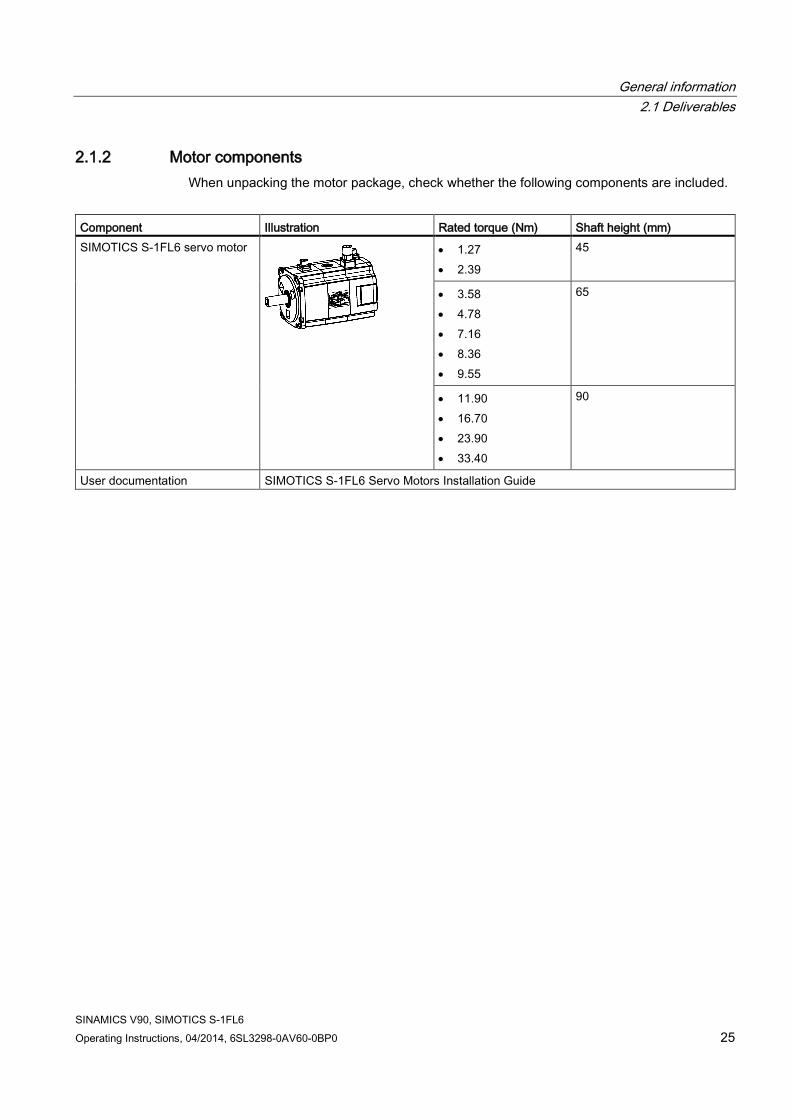
2.1.2 Motor components When unpacking the motor package, check whether the following components are included.
Component Illustration Rated torque (Nm) Shaft height (mm) SIMOTICS S-1FL6 servo motor
• 1.27 • 2.39
45
• 3.58 • 4.78 • 7.16 • 8.36 • 9.55
65
• 11.90 • 16.70 • 23.90 • 33.40
90
User documentation SIMOTICS S-1FL6 Servo Motors Installation Guide

General information 2.1 Deliverables
SINAMICS V90, SIMOTICS S-1FL6 26 Operating Instructions, 04/2014, 6SL3298-0AV60-0BP0
Motor rating plate
① Motor type ⑦ Rated power ⑬ Rated current
② Order number ⑧ Encoder type and resolution ⑭ Holding brake
③ Serial number ⑨ Thermal class ⑮ Motor ID
④ Rated torque ⑩ Degree of protection ⑯ Weight
⑤ Stall torque ⑪ Motor operating mode ⑰ Maximum speed
⑥ Rated voltage ⑫ Stall current ⑱ Rated speed

General information 2.2 Device combination
SINAMICS V90, SIMOTICS S-1FL6 Operating Instructions, 04/2014, 6SL3298-0AV60-0BP0 27
2.2 Device combination The table below shows the combination of SINAMICS V90 servo drives and SIMOTICS S-1FL6 servo motors.
SIMOTICS S-1FL6 servo motor SINAMICS V90 servo drive Rated torque (Nm)
Rated power (kW)
Rated speed (rpm)
Shaft height (mm)
Order number1) Order number Frame size
1.27 0.4 3000 45 1FL6042-1AF61-0❑❑1 6SL3210-5FE10-4UA0 FSAA 2.39 0.75 3000 45 1FL6044-1AF61-0❑❑1 6SL3210-5FE10-8UA0
FSA 3.58 0.75 2000 65 1FL6061-1AC61-0❑❑1
6SL3210-5FE11-0UA0
4.78 1.0 2000 65 1FL6062-1AC61-0❑❑1
7.16 1.5 2000 65 1FL6064-1AC61-0❑❑1
6SL3210-5FE11-5UA0
FSB 8.36 1.75 2000 65 1FL6066-1AC61-
0❑❑1 9.55 2.0 2000 65 1FL6067-1AC61-
0❑❑1 6SL3210-5FE12-0UA0
11.9 2.5 2000 90 1FL6090-1AC61-0❑❑1
16.7 3.5 2000 90 1FL6092-1AC61-0❑❑1
6SL3210-5FE13-5UA0 FSC
23.9 5.0 2000 90 1FL6094-1AC61-0❑❑1
6SL3210-5FE15-0UA0
33.4 7.0 2000 90 1FL6096-1AC61-0❑❑1
6SL3210-5FE17-0UA0
1) The symbol ❑❑ in the motor order numbers is for optional configurations (encoder type and mechanics). Refer to the motor rating plate explanation in Motor components (Page 25) for detailed information.

General information 2.3 Product overview
SINAMICS V90, SIMOTICS S-1FL6 28 Operating Instructions, 04/2014, 6SL3298-0AV60-0BP0
2.3 Product overview
SINAMICS V90 servo drives ● FSAA and FSA
● FSB and FSC

General information 2.4 System configuration
SINAMICS V90, SIMOTICS S-1FL6 Operating Instructions, 04/2014, 6SL3298-0AV60-0BP0 29
SIMOTICS S-1FL6 servo motors
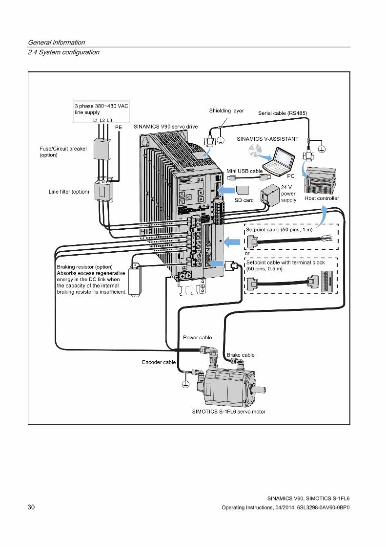
2.4 System configuration The SINAMICS V90 servo drive is integrated with digital input/output interface, pulse train interface and analog interface. It can be connected either to a Siemens controller like S7-200, S7-1200 or S7-200 SMART, or to a third-party controller. Absolute position information can be read from the servo drive by the PLC via RS485 port.
A configuration software tool, SINAMICS V-ASSISTANT, can be installed on a PC. The PC can communicate with SINAMICS V90 servo drive with a USB cable for performing parameter settings, trial run, status display monitoring, gain adjustments, and so on.
The following illustration shows an example of the SINAMICS V90 servo system configuration:
General information 2.4 System configuration
SINAMICS V90, SIMOTICS S-1FL6 30 Operating Instructions, 04/2014, 6SL3298-0AV60-0BP0

General information 2.5 Accessories
SINAMICS V90, SIMOTICS S-1FL6 Operating Instructions, 04/2014, 6SL3298-0AV60-0BP0 31
2.5 Accessories
Cables and connectors The illustration below shows cables between the drive and the motor and configurable cable connectors:
You can select cables and connectors according to the table below:
MOTION-CONNECT 300 cable Cable connector
(motor side) Cable connector (drive side)
Type Length Order No. 6FX3002-...
Type Order No. 6FX2003-...
Type Order No. 6FX2003-...
Brake cable (a1)
3 m 5BL02-1AD0 Brake connector (a2)
0LL51 - - 5 m 5BL02-1AF0 7 m 5BL02-1AH0 10 m 5BL02-1BA0 20 m 5BL02-1CA0
Power cable for FSA/FSAA (b1)
3 m 5CL01-1AD0 Power connector (b2)
0LL11 - - 5 m 5CL01-1AF0 7 m 5CL01-1AH0 10 m 5CL01-1BA0
General information 2.5 Accessories
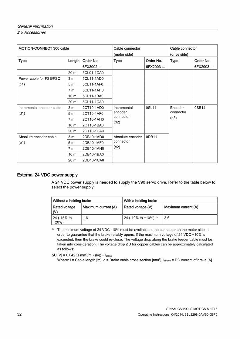
SINAMICS V90, SIMOTICS S-1FL6 32 Operating Instructions, 04/2014, 6SL3298-0AV60-0BP0
MOTION-CONNECT 300 cable Cable connector (motor side)
Cable connector (drive side)
Type Length Order No. 6FX3002-...
Type Order No. 6FX2003-...
Type Order No. 6FX2003-...
20 m 5CL01-1CA0 Power cable for FSB/FSC (c1)
3 m 5CL11-1AD0 5 m 5CL11-1AF0 7 m 5CL11-1AH0 10 m 5CL11-1BA0 20 m 5CL11-1CA0
Incremental encoder cable (d1)
3 m 2CT10-1AD0 Incremental encoder connector (d2)
0SL11
Encoder connector (d3)
0SB14 5 m 2CT10-1AF0 7 m 2CT10-1AH0 10 m 2CT10-1BA0 20 m 2CT10-1CA0
Absolute encoder cable (e1)
3 m 2DB10-1AD0 Absolute encoder connector (e2)
0DB11 5 m 2DB10-1AF0
7 m 2DB10-1AH0 10 m 2DB10-1BA0 20 m 2DB10-1CA0
External 24 VDC power supply A 24 VDC power supply is needed to supply the V90 servo drive. Refer to the table below to select the power supply:
Without a holding brake With a holding brake Rated voltage (V)
Maximum current (A) Rated voltage (V) Maximum current (A)
24 (-15% to +20%)
1.6 24 (-10% to +10%) 1) 3.6
1) The minimum voltage of 24 VDC -10% must be available at the connector on the motor side in order to guarantee that the brake reliably opens. If the maximum voltage of 24 VDC +10% is exceeded, then the brake could re-close. The voltage drop along the brake feeder cable must be taken into consideration. The voltage drop ΔU for copper cables can be approximately calculated as follows:
ΔU [V] = 0.042 Ω·mm2/m ∙ (l/q) ∙ IBrake Where: l = Cable length [m], q = Brake cable cross section [mm2], IBrake = DC current of brake [A]

General information 2.5 Accessories
SINAMICS V90, SIMOTICS S-1FL6 Operating Instructions, 04/2014, 6SL3298-0AV60-0BP0 33
Fuse/circuit breaker A fuse/circuit breaker can be used to protect the system. Refer to the table below for the selection of fuses and circuit breakers:
SINAMICS V90 CE-compliant UL-compliant Frame size
Order number Standard fuse Circuit breaker Standard fuse Circuit breaker
Rated current (A)
Order Number
Order number Rated current (A)
Class Order number
FSAA 6SL3210-5FE10-4UA0
6 3NA3 801-6 3RV 1021-1DA10
10 A, 600 VAC
J 3RV 1021-1DA10
FSA 6SL3210-5FE10-8UA0
6 3NA3 801-6 3RV 1021-1EA10
J 3RV 1021-1EA10
6SL3210-5FE11-0UA0
10 3NA3 803-6 3RV 1021-1FA10
J 3RV 1021-1FA10
FSB
6SL3210-5FE11-5UA0
16 3NA3 805-6 3RV 1021-1JA10
15 A, 600 VAC
J 3RV 1021-1JA10
6SL3210-5FE12-0UA0
16 3NA3 805-6 3RV 1021-4AA10
J 3RV 1021-4AA10
FSC 6SL3210-5FE13-5UA0
25 3NA3 807-6 3RV 1021-4BA10
25 A, 600 VAC
J 3RV 1021-4BA10
6SL3210-5FE15-0UA0
25 3NA3 810-6 3RV 1021-4DA10
J 3RV 1021-4DA10
6SL3210-5FE17-0UA0
25 3NA3 810-6 3RV 1021-4DA10
J 3RV 1021-4DA10
Braking resistor The SINAMICS V90 has a built-in braking resistor, the table below shows the information of the built-in resistor:
Frame size Resistance (Ω) Max. power (kW) Rated power (W) Max. energy (kJ)
FSAA 533 1.2 17 1.8 FSA 160 4 57 6 FSB 70 9.1 131 13.7 FSC 27 23.7 339 35.6
When the internal braking resistor cannot meet the braking requirements, an external braking resistor can be used to transform the regenerative electrical energy into heat, thus giving greatly improved braking and deceleration capabilities. Select a standard braking resistor according to the table below:
Frame size Resistance (Ω) Max. power (kW) Rated power (W) Max. energy (kJ)
FSAA 533 1.2 30 2.4 FSA 160 4 100 8 FSB 70 9.1 229 18.3 FSC 27 23.7 1185 189.6

General information 2.5 Accessories
SINAMICS V90, SIMOTICS S-1FL6 34 Operating Instructions, 04/2014, 6SL3298-0AV60-0BP0
Filter Siemens recommends you to use a line filter to protect the system from high frequency noise.
The table below lists all filters recommended by Siemens:
Frame size Rated current (A) Degree of protection Order number
FSAA 5 IP20 6SL3203-0BE15-0VA0 FSA 5 IP20 6SL3203-0BE15-0VA0 FSB 12 IP20 6SL3203-0BE21-2VA0 FSC 20 IP20 6SL3203-0BE22-0VA0
Installation
Connecting the line filter to the drive

General information 2.6 Function list
SINAMICS V90, SIMOTICS S-1FL6 Operating Instructions, 04/2014, 6SL3298-0AV60-0BP0 35
SD card Optionally an SD card can be used to copy drive parameters or perform a firmware update. You are recommended to use the SIEMENS SD card (order number: 6ES7954-8LB01-0AA0).
You can also select other high quality SD cards with a maximum capacity of 2 GB from manufacturers such as KINGMAX, Kingston or SanDisk.
Replacement fans (for frame sizes B and C only) Order numbers:
Fan kits for frame size B: 6SL3200-0WF00-0AA0
Fan kits for frame size C: 6SL3200-0WF01-0AA0
2.6 Function list
Function Description Control mode Pulse train input position control (PTI) (Page 133)
Implements accurate positioning through two pulse train input channels: 5 V differential or 24 V single end signal. In addition, it supports S-curve position smoothing function
PTI
Internal position control (IPos) (Page 146)
Implements accurate positioning through internal position commands (up to eight groups) and allows to specify the acceleration/speed for positioning
IPos
Speed control (S) (Page 162) Flexibly controls motor speed and direction through external analog speed commands (0 - ±10 VDC) or internal speed commands (up to seven groups)
S
Torque control (T) (Page 168) Flexibly controls motor output torque through external analog torque commands (0 - ±10 VDC) or internal torque commands. In addition, it supports speed limit function to prevent overspeed when a motor has no loads
T
Compound controls (Page 125) Supports flexible switches among position control mode, speed control mode, and torque control mode
PTI/S, IPos/S, PTI/T, IPos/T, S/T
Absolute position system (Page 172)
Allows to implement motion control tasks immediately after the servo system with an absolute encoder is powered on, needless of carrying out referencing or zero position operation beforehand
PTI
Gain switching (Page 206) Switches between gains during motor rotation or stop with an external signal or internal parameters to reduce noise and positioning time, or improve the operation stability of a servo system
PTI, IPos, S
PI/P switching (Page 210) Switches from PI control to P control with an external signal or internal parameters to suppress overshooting during acceleration or deceleration (for speed control mode) or to suppress undershooting during positioning and reduce the settling time (for position control mode)
PTI, IPos, S
Safe Torque Off (STO) (Page 191) Safely disconnects torque-generating motor power supply to prevent an unintentional motor restart
PTI, IPos, S, T

General information 2.6 Function list
SINAMICS V90, SIMOTICS S-1FL6 36 Operating Instructions, 04/2014, 6SL3298-0AV60-0BP0
Function Description Control mode Zero speed clamp (Page 166) Stops motor and clamps the motor shaft when motor speed
setpoint is below a parameterized threshold level S
Real-time auto tuning (Page 200) Estimates the machine characteristic and sets the closed loop control parameters (position loop gain, speed loop gain, speed integral compensation, filter if necessary, etc.) continuously in real time without any user intervention
PTI, IPos, S
Resonance suppression (Page 203) Suppresses the mechanical resonance, such as workpiece vibration and base shake
PTI, IPos, S, T
Speed limit (Page 140) Limits motor speed through external analog speed limit commands (0 - ±10 VDC) or internal speed limit commands (up to three groups)
PTI, IPos, S, T
Torque limit (Page 141) Limits motor torque through external analog torque limit commands (0 - ±10 VDC) or internal torque limit commands (up to three groups)
PTI, IPos, S
Electronic gear ratio (Page 136) Defines a multiplier factor for input pulses PTI, IPos Basic operator panel (BOP) (Page 107)
Displays servo status on a 6-digit 7-segment LED display PTI, IPos, S, T
External braking resistor - DCP, R1 (Page 94)
An external braking resistor can be used when the internal braking resistor is insufficient for regenerative energy
PTI, IPos, S, T
Digital inputs/outputs (DIs/DOs) (Page 61)
Control signals and status signals can be assigned to eight programmable digital inputs and six digital outputs
PTI, IPos, S, T
Smoothing function (Page 135) Transforms position characteristics from the pulse train input setpoint into an S-curve profile with a parameterized time constant
PTI
SINAMICS V-ASSISTANT You can perform parameter settings, test operation, adjustment and other operations with a PC
PTI, IPos, S, T
General information 2.7 Technical data
SINAMICS V90, SIMOTICS S-1FL6 Operating Instructions, 04/2014, 6SL3298-0AV60-0BP0 37
2.7 Technical data
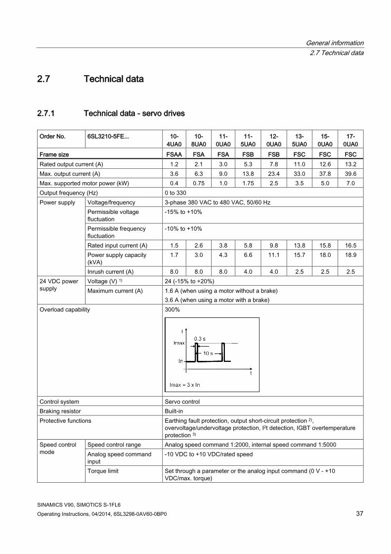
2.7.1 Technical data - servo drives Order No. 6SL3210-5FE... 10-
4UA0 10-
8UA0 11-
0UA0 11-
5UA0 12-
0UA0 13-
5UA0 15-
0UA0 17-
0UA0 Frame size FSAA FSA FSA FSB FSB FSC FSC FSC Rated output current (A) 1.2 2.1 3.0 5.3 7.8 11.0 12.6 13.2 Max. output current (A) 3.6 6.3 9.0 13.8 23.4 33.0 37.8 39.6 Max. supported motor power (kW) 0.4 0.75 1.0 1.75 2.5 3.5 5.0 7.0 Output frequency (Hz) 0 to 330 Power supply Voltage/frequency 3-phase 380 VAC to 480 VAC, 50/60 Hz
Permissible voltage fluctuation
-15% to +10%
Permissible frequency fluctuation
-10% to +10%
Rated input current (A) 1.5 2.6 3.8 5.8 9.8 13.8 15.8 16.5 Power supply capacity (kVA)
1.7 3.0 4.3 6.6 11.1 15.7 18.0 18.9
Inrush current (A) 8.0 8.0 8.0 4.0 4.0 2.5 2.5 2.5 24 VDC power supply
Voltage (V) 1) 24 (-15% to +20%) Maximum current (A) 1.6 A (when using a motor without a brake)
3.6 A (when using a motor with a brake) Overload capability 300%
Control system Servo control Braking resistor Built-in Protective functions Earthing fault protection, output short-circuit protection 2),
overvoltage/undervoltage protection, I2t detection, IGBT overtemperature protection 3)
Speed control mode
Speed control range Analog speed command 1:2000, internal speed command 1:5000 Analog speed command input
-10 VDC to +10 VDC/rated speed
Torque limit Set through a parameter or the analog input command (0 V - +10 VDC/max. torque)

General information 2.7 Technical data
SINAMICS V90, SIMOTICS S-1FL6 38 Operating Instructions, 04/2014, 6SL3298-0AV60-0BP0
Order No. 6SL3210-5FE... 10-4UA0
10- 8UA0
11-0UA0
11-5UA0
12- 0UA0
13-5UA0
15-0UA0
17-0UA0
Frame size FSAA FSA FSA FSB FSB FSC FSC FSC Position control mode
Max. input pulse frequency 1 M (differential input), 200 kpps (open collector input) Command pulse multiplying factor
Electronic gear ratio (A/B) A: 1 - 10000, B: 1 - 10000 1/50 < A/B < 200
In-position range setting 0 to ±10000 pulse (command pulse unit) Error excessive ±10 revolutions Torque limit Set through a parameter or the analog input command (0 V - +10
VDC/max. torque) Torque control mode
Analog torque command input
-10 V to +10 VDC/max. torque (input impedance 10 kΩ - 12 kΩ)
Speed limit Set through a parameter or the analog input command (0 V - +10 VDC/max. rated speed)
Cooling method Self-cooled Fan-cooled Environmental conditions
Surrounding air temperature
Operation 0 °C to 45 °C: without power derating 45 °C to 55 °C: with power derating
Storage -40 °C to +70 °C Surrounding humidity
Operation < 90% (non-condensing) Storage 90% (non-condensing)
Operating environment Indoors (without direct sunlight), free from corrosive gas, combustible gas, oil gas, or dust
Altitude ≤ 1000 m (without power derating)
Degree of protection IP20 Degree of pollution Class 2 Vibration Operation Shock: Operational area II
Peak acceleration: 5 g Duration of shock: 30 ms

General information 2.7 Technical data
SINAMICS V90, SIMOTICS S-1FL6 Operating Instructions, 04/2014, 6SL3298-0AV60-0BP0 39
Order No. 6SL3210-5FE... 10-4UA0
10- 8UA0
11-0UA0
11-5UA0
12- 0UA0
13-5UA0
15-0UA0
17-0UA0
Frame size FSAA FSA FSA FSB FSB FSC FSC FSC Vibration:
Operational area II 10 Hz to 58 Hz: 0.075 mm deflection 58 Hz to 200 Hz: 1g vibration
Transport & storage
Vibration:
5 Hz to 9 Hz: 7.5 mm deflection 9 Hz to 200 Hz: 2 g vibration Vibration class: 2M3 transportation
Certifications
Mechanical design
Outline dimensions (W x H x D, mm)
60 x 180 x 200
80 x 180 x 200 100 x 180 x 220 140 x 260 x 240
Weight (kg) 1.800 2.500 2.510 3.055 3.130 6.515 6.615 6.615 1) When SINAMICS V90 works with a motor with a brake, the voltage tolerance of 24 VDC power supply must be -10% to
+10% to meet the voltage requirement of the brake. 2) Integral solid state short circuit protection does not provide branch circuit protection. Branch circuit protection must be
provided in accordance with the National Electrical Code and any additional local codes. 3) SINAMICS V90 does not support motor overtemperature protection. Motor overtemperature is calculated by I2t and
protected by the output current from the drive.
2.7.2 Technical data - servo motors
General technical data Parameter Description Type of motor Permanent-magnet synchronous motor Cooling Self-cooled Operating temperature [°C] 0 to 40 (without power derating) Storage temperature [°C] -15 to +65 Relative humidity [RH] 90% (non-condensing at 30°C ) Installation altitude [m] ≤ 1000 (without power derating) Maximum noise level [dB] 1FL604❑: 65 1FL606❑ :70 1FL609❑: 70 Thermal class B Vibration severity grade A (according to IEC 60034-14) Shock resistance [m/s2] 25 (continuous in axial direction); 50 (continuous in radial direction); 250
(in a short time of 6 ms)
Rated voltage (V) 24 ± 10% Rated current (A) 1FL604❑: 0.88 1FL606❑ : 1.44 1FL609❑: 1.88

General information 2.7 Technical data
SINAMICS V90, SIMOTICS S-1FL6 40 Operating Instructions, 04/2014, 6SL3298-0AV60-0BP0
Parameter Description Holding brake
Holding brake torque [Nm] 1FL604❑: 3.5 1FL606❑ : 12 1FL609❑: 30 Maximum brake opening time [ms]
1FL604❑: 60 1FL606❑ : 180 1FL609❑: 220
Maximum brake closing time [ms]
1FL604❑: 45 1FL606❑ : 60 1FL609❑: 115
Maximum number of emergency stops
2000 1)
Bearing lifetime [h] > 20000 2) Oil seal lifetime [h] 5000 Encoder lifetime [h] 20000 - 30000 3) Paint finish Black Degree of protection IP65, with shaft oil seal Type of construction IM B5, IM V1 and IM V3 Positive rotation
Clockwise (default setting in SINAMICS V90 servo drives)
Certification
1) Restricted emergency stop operation is permissible. Up to 2000 braking operations can be executed with 300% rotor moment of inertia as external moment of inertia from a speed of 3000 RPM without the brake being subject to an inadmissible amount of wear.
2) This lifetime is only for reference. When a motor keeps running at rated speed under rated load, replace its bearing after 20,000 to 30,000 hours of service time. Even if the time is not reached, the bearing must be replaced when unusual noise, vibration, or faults are found.
3) This lifetime is only for reference. When a motor keeps running at 80% rated value and the surrounding temperature is 30 °C, the encoder lifetime can be ensured.
Specific technical data Order No. 1FL60... 42 44 61 62 64 66 67 90 92 94 96 Rated power [kW] 0.40 0.75 0.75 1.00 1.50 1.75 2.00 2.5 3.5 5.0 7.0 1) Rated torque [Nm] 1.27 2.39 3.58 4.78 7.16 8.36 9.55 11.9 16.7 23.9 33.4 Maximum torque [Nm]
3.8 7.2 10.7 14.3 21.5 25.1 28.7 35.7 50.0 70.0 90.0
Rated speed [rpm] 3000 2000 2000 Maximum speed [rpm]
4000 3000 3000 2500 2000
Rated frequency [Hz] 200 133 133 Rated current [A] 1.2 2.1 2.5 3.0 4.6 5.3 5.9 7.8 11.0 12.6 13.2

General information 2.7 Technical data
SINAMICS V90, SIMOTICS S-1FL6 Operating Instructions, 04/2014, 6SL3298-0AV60-0BP0 41
Order No. 1FL60... 42 44 61 62 64 66 67 90 92 94 96 Maximum current [A] 3.6 6.3 7.5 9.0 13.8 15.9 17.7 23.4 33.0 36.9 35.6 Moment of inertia [10-
4 kgm2] 2.7 5.2 8.0 15.3 15.3 22.6 29.9 47.4 69.1 90.8 134.3
Moment of inertia (with brake) [10-4 kgm2]
3.2 5.7 9.1 16.4 16.4 23.7 31.0 56.3 77.9 99.7 143.2
Recommended load to motor inertia ration
< 1000% < 500% < 500%
Weight of incremental encoder motor [kg]
With brake
4.6 6.4 8.6 11.3 11.3 14.0 16.6 21.3 25.7 30.3 39.1
Without brake
3.3 5.1 5.6 8.3 8.3 11.0 13.6 15.3 19.7 24.3 33.2
Weight of absolute encoder motor [kg]
With brake
4.4 6.2 8.3 11.0 11.0 13.6 16.3 20.9 25.3 29.9 38.7
Without brake
3.1 4.9 5.3 8.0 8.0 10.7 13.3 14.8 19.3 23.9 32.7
1) When the surrounding temperature is higher than 30 °C, the 1FL6096 motors with brake will have a power derating of 10%.
Note
The data of rated torque, rated power, maximum torque, and armature resistance in the above table allow a tolerance of 10%.

General information 2.7 Technical data
SINAMICS V90, SIMOTICS S-1FL6 42 Operating Instructions, 04/2014, 6SL3298-0AV60-0BP0
Torque-Speed characteristics

General information 2.7 Technical data
SINAMICS V90, SIMOTICS S-1FL6 Operating Instructions, 04/2014, 6SL3298-0AV60-0BP0 43
Note • Continuous operating area is a series of states when a motor can operate continuously
and safely. The effective torque must be located in this area. • Short-term operating area is a series of states when a motor can operate for a short
duration if its effective torque is smaller than the rated torque. • For the motors with different rated and maximum speeds, the output torque will decline at
a faster rate after the speed exceeds the rated speed. • The feature in short-term operating area varies with power supply voltages. • The continuous operating area becomes smaller and the voltage drop grows larger when
the cables in the major loop exceed 20 meters. • For 1FL6096 motors, the maximum speed can be ensured when the line supply voltage is
higher than 380V.
Permissible radial and axial forces

General information 2.7 Technical data
SINAMICS V90, SIMOTICS S-1FL6 44 Operating Instructions, 04/2014, 6SL3298-0AV60-0BP0
Note
1FL604❑ and 1FL609❑ have a 5 mm of shaft sheltered in sleeves, and 1FL606❑ has an 8 mm of shaft in sleeves. Therefore, the distances to flange in the above three figures begin respectively from 5 mm, 8mm, and 5 mm.
2.7.3 Technical data - cables Parameter MOTION-CONNECT 300
Power Cable MOTION-CONNECT 300 Encoder Cable
MOTION-CONNECT 300 Brake Cable
Material PVC PVC PVC Degree of protection (motor-side only)
IP65 IP65 IP65
Number of cores 4 10 2 Cross-section of cores (mm2) 4 x 1.5 (for FSAA/FSA)
4 x 2.5 (for FSB/FSC) 6 x 0.22 + 4 x 0.25 2 x 0.75
Rated voltage (V) 600/1000 30 30 Operation temperature (°C) -25 to 80 Shielding Yes Minimum bending radius, static (mm)
6 x outer diameter
Bending cycles 1000000 Oil resistance EN60811-2-1 fulfilled Flame-retardant EN60332-1-1to 1-3 fulfilled Certifications RoHS, UL, CE

SINAMICS V90, SIMOTICS S-1FL6 Operating Instructions, 04/2014, 6SL3298-0AV60-0BP0 45
Mounting 3 3.1 Mounting the drive
For mounting conditions, see Technical data - servo drives (Page 37).
3.1.1 Mounting orientation and clearance Mount the drive vertically in a shielded cabinet and observe the mounting clearances specified in the illustration below:
Note
If the left and right distances of the drive are less than 10 mm at the same time, the drive should be derated to 80%.

Mounting 3.1 Mounting the drive
SINAMICS V90, SIMOTICS S-1FL6 46 Operating Instructions, 04/2014, 6SL3298-0AV60-0BP0
3.1.2 Drill patterns and outline dimensions

Mounting 3.1 Mounting the drive
SINAMICS V90, SIMOTICS S-1FL6 Operating Instructions, 04/2014, 6SL3298-0AV60-0BP0 47

Mounting 3.2 Mounting the motor
SINAMICS V90, SIMOTICS S-1FL6 48 Operating Instructions, 04/2014, 6SL3298-0AV60-0BP0
3.1.3 Mounting the drive
Note
Taking EMC factors into account, you are recommended to mount the drive in a shielded cabinet.
3.2 Mounting the motor For mounting conditions, see Technical data - servo motors (Page 39).

Mounting 3.2 Mounting the motor
SINAMICS V90, SIMOTICS S-1FL6 Operating Instructions, 04/2014, 6SL3298-0AV60-0BP0 49
3.2.1 Mounting orientation and dimensions
Mounting orientation SIMOTICS S-1FL6 supports flange mounting only and three types of constructions, so it can be installed in three orientations as shown in the following figure.
Note When configuring the IM V3 type of construction, pay particular attention to the permissible axial force (weight force of the drive elements) and the necessary degree of protection.
Motor dimensions
Shaft-height 45 mm, with incremental encoder (unit: mm)
Rated power Rated torque k k1 a b b1 0.4 kW 1.27 Nm 154.5 201 169.5 15 61.5 0.75 kW 2.39 Nm 201.5 248 216.5

Mounting 3.2 Mounting the motor
SINAMICS V90, SIMOTICS S-1FL6 50 Operating Instructions, 04/2014, 6SL3298-0AV60-0BP0
Shaft-height 45 mm, with absolute encoder (unit: mm)
Rated power Rated torque k k1 a b b1 0.4 kW 1.27 Nm 157 203.5 172 15 61.5 0.75 kW 2.39 Nm 204 250.5 219
Shaft-height 65 mm, with incremental encoder (unit: mm)

Mounting 3.2 Mounting the motor
SINAMICS V90, SIMOTICS S-1FL6 Operating Instructions, 04/2014, 6SL3298-0AV60-0BP0 51
Rated power Rated torque k k1 a b b1 0.75 kW 3.58 Nm 148 202.5 163 15 69.5 1.0 kW 4.78 Nm 181 235.5 196 1.5 kW 7.16 Nm 181 235.5 196 1.75 kW 8.36 Nm 214 268.5 229 2.0 kW 9.55 Nm 247 301.5 262
Shaft-height 65 mm, with absolute encoder (unit: mm)
Rated power Rated torque k k1 a b b1 0.75 kW 3.58 Nm 151 205.5 166 15 69.5 1.0 kW 4.78 Nm 184 238.5 199 1.5 kW 7.16 Nm 184 238.5 199 1.75 kW 8.36 Nm 217 271.5 232 2.0 kW 9.55 Nm 250 304.5 265

Mounting 3.2 Mounting the motor
SINAMICS V90, SIMOTICS S-1FL6 52 Operating Instructions, 04/2014, 6SL3298-0AV60-0BP0
Shaft-height 90 mm, with incremental encoder (unit: mm)
Rated power Rated torque k k1 a b b1 2.5 kW 11.9 Nm 189.5 255 210.5 33 98.5 3.5 kW 16.7 Nm 211.5 281 236.5 5.0 kW 23.9 Nm 237.5 307 262.5 7.0 kW 33.4 Nm 289.5 359 314.5
Shaft-height 90 mm, with absolute encoder (unit: mm)

Mounting 3.2 Mounting the motor
SINAMICS V90, SIMOTICS S-1FL6 Operating Instructions, 04/2014, 6SL3298-0AV60-0BP0 53
Rated power Rated torque k k1 a b b1 2.5 kW 11.9 Nm 197 263 218 33 98.5 3.5 kW 16.7 Nm 223 289 244 5.0 kW 23.9 Nm 249 315 270 7.0 kW 33.4 Nm 301 367 322
3.2.2 Mounting the motor
WARNING
Personal injury and material damage
Some motors, especially the 1FL609❑ are heavy. The excessive weight of the motor should be considered and any necessary assistance required for mounting should be sought.
Otherwise, the motor can fall down during mounting. This can result in serious personal injury or material damage.
NOTICE
Damage to the motor
If the liquid enters the motor, the motor may be damaged
During motor installation or operation, make sure that no liquid (water, oil, etc.) can penetrate into the motor. Besides, when installing the motor horizontally, make sure that the cable outlet faces downward to protect the motor from ingress of oil or water.
Note Using the eyebolts
The 1FL609❑ motor (90 mm shaft height) has two M8 screw holes for screwing in two eyebolts. Lift the 1FL609❑ motor only at the eyebolts.
Eyebolts that have been screwed in must be either tightened or removed after mounting.
To ensure better heat dissipation, install a flange between the machine and the motor. You can install the motor onto the flange with 4 screws as shown in the following figure.

Mounting 3.2 Mounting the motor
SINAMICS V90, SIMOTICS S-1FL6 54 Operating Instructions, 04/2014, 6SL3298-0AV60-0BP0
The information about the screws and the flange is as follows:
Motor Screw Recommended flange size Tightening torque Flange material 1FL604❑ 4 x M6 210 x 210 x 10 (mm) 8 Nm Aluminum alloy 1FL606❑ 4 x M8 350 x 350 x 20 (mm) 20 Nm 1FL609❑ 4 x M12 400 x 400 x 25 (mm) 85 Nm

SINAMICS V90, SIMOTICS S-1FL6 Operating Instructions, 04/2014, 6SL3298-0AV60-0BP0 55
Connecting 4 4.1 System connection
The SINAMICS V90 servo system is connected as follows:

Connecting 4.1 System connection
SINAMICS V90, SIMOTICS S-1FL6 56 Operating Instructions, 04/2014, 6SL3298-0AV60-0BP0
NOTICE
Important wiring information
In order to meet EMC requirements, all cables must be shielded cables.
The cable shields of shielded twisted-pair cables should be connected to the shielding plate or the cable clamp of the servo drive.
Connecting the cable shields with the shielding plate To achieve EMC-compliant installation of the drive, use the shielding plate that is shipped with the drive to connect the cable shields. See the following example for steps to connect cable shields with the shielding plate:

Connecting 4.2 Main circuit wirings
SINAMICS V90, SIMOTICS S-1FL6 Operating Instructions, 04/2014, 6SL3298-0AV60-0BP0 57
Adjusting cable orientations from the motor side From the motor side, you can adjust the orientation of the power cable, encoder cable, and brake cable to facilitate cable connection.
Note Rotating the connectors
All the three motor-side connectors can be rotated only within 360°.
4.2 Main circuit wirings
4.2.1 Line supply - L1, L2, L3
Signal Description 400 V variant
L1 Line phase L1 L2 Line phase L2 L3 Line phase L3
Maximum conductor cross-section: FSAA and FSA: 1.5 mm2 (M2.5 screws, 0.5 Nm) FSB and FSC: 2.5 mm2 (M4 screws, 2.25 Nm)
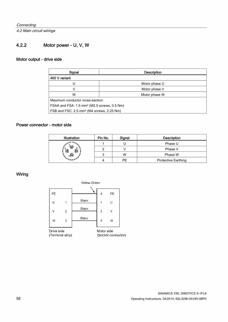
Connecting 4.2 Main circuit wirings
SINAMICS V90, SIMOTICS S-1FL6 58 Operating Instructions, 04/2014, 6SL3298-0AV60-0BP0
4.2.2 Motor power - U, V, W
Motor output - drive side
Signal Description 400 V variant
U Motor phase U V Motor phase V W Motor phase W
Maximum conductor cross-section: FSAA and FSA: 1.5 mm2 (M2.5 screws, 0.5 Nm) FSB and FSC: 2.5 mm2 (M4 screws, 2.25 Nm)
Power connector - motor side
Illustration Pin No. Signal Description
1 U Phase U 2 V Phase V 3 W Phase W 4 PE Protective Earthing
Wiring

Connecting 4.3 Control/Status interface - X8
SINAMICS V90, SIMOTICS S-1FL6 Operating Instructions, 04/2014, 6SL3298-0AV60-0BP0 59
Plugging the motor power cable (FSAA and FSA)
Note
The FSB and FSC servo drives are equipped with barrier terminals for motor power connection. You can fix the motor power cable using the M4 screws with the tightening torque of 2.25 Nm on the servo drives.
4.3 Control/Status interface - X8 Signal type Pin
No. Signal Description Pin
No. Signal Description
Type: 50-pin MDR socket Pulse train inputs (PTI)/Pulse train encoder outputs (PTO)
1, 2, 26, 27
Position setpoint with pulse train input. Exclusive for high-speed 5 V differential pulse train input Maximum frequency: 1MHz Signal transmission of this channel has better noise immunity.
36, 37, 38, 39
Position setpoint with pulse train input. 24 V single end pulse train input Maximum frequency: 200 kHz
15, 16, 40, 41
Encoder emulation pulse output with high-speed 5 V differential signals (A+/A-, B+/B-)
42, 43
Encoder Zero phase pulse output with high-speed 5 V differential signals
17 Encoder Zero phase pulse output with open collector
1 PTIA_D+ High-speed 5 V differential pulse train input A (+)
15 PTOA+ High-speed 5 V differential pulse train encoder output A (+)

Connecting 4.3 Control/Status interface - X8
SINAMICS V90, SIMOTICS S-1FL6 60 Operating Instructions, 04/2014, 6SL3298-0AV60-0BP0
Signal type Pin No.
Signal Description Pin No.
Signal Description
2 PTIA_D- High-speed 5 V differential pulse train input A (-)
16 PTOA- High-speed 5 V differential pulse train encoder output A (-)
26 PTIB_D+ High-speed 5 V differential pulse train input B (+)
40 PTOB+ High-speed 5 V differential pulse train encoder output B (+)
27 PTIB_D- High-speed 5 V differential pulse train input B (-)
41 PTOB- High-speed 5 V differential pulse train encoder output B (-)
36 PTIA_24P 24 V pulse train input A, positive
42 PTOZ+ High-speed 5 V differential pulse train encoder output Z (+)
37 PTIA_24M 24 V pulse train input A, ground
43 PTOZ- High-speed 5 V differential pulse train encoder output Z (-)
38 PTIB_24P 24 V pulse train input B, positive
17 PTOZ (OC) Pulse train encoder output Z signal (open collector output)
39 PTIB_24M 24 V pulse train input B, ground
Digital inputs/outputs
3 DI_COM Common terminal for digital inputs
14 DI10 Digital input 10
4 DI_COM Common terminal for digital inputs
28 P24V_DO External 24 V supply for digital outputs
5 DI1 Digital input 1 29 P24V_DO External 24 V supply for digital outputs
6 DI2 Digital input 2 30 DO1 Digital output 1 7 DI3 Digital input 3 31 DO2 Digital output 2 8 DI4 Digital input 4 32 DO3 Digital output 3 9 DI5 Digital input 5 33 DO4 Digital output 4 10 DI6 Digital input 6 34 DO5 Digital output 5 11 DI7 Digital input 7 35 DO6 Digital output 6 12 DI8 Digital input 8 49 MEXT_DO External 24 V ground for
digital outputs 13 DI9 Digital input 9 50 MEXT_DO External 24 V ground for
digital outputs Analog inputs/outputs
18 P12AI 12 V power output for analog input
45 AO_M Analog output ground
19 AI1+ Analog input channel 1, positive
46 AO1 Analog output channel 1
20 AI1- Analog input channel 1, negative
47 AO_M Analog output ground
21 AI2+ Analog input channel 2, positive
48 AO2 Analog output channel 2
22 AI2- Analog input channel 2, negative
None 23 - Reserved 25 - Reserved 24 - Reserved 44 - Reserved

Connecting 4.3 Control/Status interface - X8
SINAMICS V90, SIMOTICS S-1FL6 Operating Instructions, 04/2014, 6SL3298-0AV60-0BP0 61
4.3.1 Digital inputs/outputs (DIs/DOs) SINAMICS V90 supports free assignment of signals to the following digital input and output terminals depending on the control mode selected: DI1 to DI8 -- Assignable with parameters p29301 to p29308 DO1 to DO6 -- Assignable with parameters p29330 to p29335
Exception: DI9 and DI10 DI9 is permanently assigned with the signal EMGS (emergency stop) and DI10 is permanently assigned with the signal C-MODE (change mode).
For detailed information about default DI/DO signal assignments, see the table below:
Pin No. Digital
inputs/outputs Parameters Default signals/values
Index 0 (PTI) Index 1 (IPos) Index 2 (S) Index 3 (T) 5 DI1 p29301 1 (SON) 1 (SON) 1 (SON) 1 (SON) 6 DI2 p29302 2 (RESET) 2 (RESET) 2 (RESET) 2 (RESET) 7 DI3 p29303 3 (CWL) 3 (CWL) 3 (CWL) 3 (CWL) 8 DI4 p29304 4 (CCWL) 4 (CCWL) 4 (CCWL) 4 (CCWL) 9 DI5 p29305 5 (G-CHANGE) 5 (G-CHANGE) 12 (CWE) 12 (CWE)
10 DI6 p29306 6 (P-TRG) 6 (P-TRG) 13 (CCWE) 13 (CCWE) 11 DI7 p29307 7 (CLR) 21 (POS1) 15 (SPD1) 18 (TSET) 12 DI8 p29308 10 (TLIM1) 22 (POS2) 16 (SPD2) 19 (SLIM1) 30 DO1 p29330 1 (RDY) 31 DO2 p29331 2 (ALM) 32 DO3 p29332 3 (INP) 33 DO4 p29333 5 (SPDR) 34 DO5 p29334 6 (TLR) 35 DO6 p29335 8 (MBR)
Note
The selected DI signal will respond with a delay time of 8 to 16 ms.

Connecting 4.3 Control/Status interface - X8
SINAMICS V90, SIMOTICS S-1FL6 62 Operating Instructions, 04/2014, 6SL3298-0AV60-0BP0
4.3.1.1 DIs You can assign a maximum of 28 internal digital input signals to the SINAMICS V90 servo drive. For detailed information about these signals, see the table below:
No. Name Type Description Control mode
PTI IPos S T 1 SON Edge
0→1 1→0
Servo-on • 0→1: powers on power circuit and makes servo
drive ready to operate. • 1→0: motor ramps down (OFF1) in PTI, IPos, and
S modes; motor coasts down (OFF2) in T mode.
✓ ✓ ✓ ✓
2 RESET Edge 0→1
Reset alarms • 0→1: Reset alarms
✓ ✓ ✓ ✓
3 CWL Edge 1→0
Clockwise over-travel limit (positive limit) • 1 = condition for operation • 1→0: emergency stop (OFF3)
✓ ✓ ✓ ✓
4 CCWL Edge 1→0
Counter-clockwise over-travel limit (negative limit) • 1 = condition for operation • 1→0: emergency stop (OFF3)
✓ ✓ ✓ ✓
5 G-CHANGE
Level Gain change between the first and the second gain parameter set. • 0: the first gain parameter set • 1: the second gain parameter set
✓ ✓ ✓ X
6 P-TRG Level Edge 0→1
In PTI mode: pulse allowable/inhibit. • 0: operation with pulse train setpoint is possible • 1: inhibit the pulse train setpoint In IPos mode: position trigger • 0→1: starts positioning of selected fixed position
setpoint
✓ ✓ X X
7 CLR Level Clear position control droop pulses. • 0: no clearing • 1: always clear
✓ X X X
8 EGEAR1 Level Electronic gear. A combination of the signals EGEAR1 and EGEAR2 can select four electronic gear ratios. EGEAR2 : EGEAR1 • 0 : 0: electronic gear ratios 1 • 0 : 1: electronic gear ratios 2 • 1 : 0: electronic gear ratios 3 • 1 : 1: electronic gear ratios 4
✓ ✓ X X 9 EGEAR2 Level ✓ ✓ X X
10 TLIM1 Level Torque limit selection. ✓ ✓ ✓ X

Connecting 4.3 Control/Status interface - X8
SINAMICS V90, SIMOTICS S-1FL6 Operating Instructions, 04/2014, 6SL3298-0AV60-0BP0 63
No. Name Type Description Control mode
PTI IPos S T 11 TLIM2 Level A combination of TLIM1 and TLIM2 can select four
torque limit sources (one external torque limit, three internal torque limits). TLIM2 : TLIM1 • 0 : 0: internal torque limit 1 • 0 : 1: external torque limit (Analog Input 2) • 1 : 0: internal torque limit 2 • 1 : 1: internal torque limit 3
12 CWE Level Enable clockwise rotations. • 1: Enable clockwise rotation, ramp up • 0: Disable clockwise rotation, ramp down
X X ✓ ✓
13 CCWE Level Enable counter-clockwise rotations. • 1: Enable counter-clockwise rotation, ramp down • 0: Disable counter-clockwise rotation, ramp up
X X ✓ ✓
14 ZSCLAMP Level Zero speed clamps. • 1 = when the motor speed setpoint is an analog
signal and lower than the threshold level (P_zclamp_threshold), the motor is clamped.
• 0 = no action
X X ✓ X
15 SPD1 Level Select speed mode: fixed speed setpoint. A combination of the signals SPD1, SPD2 and SPD3 can select eight speed setpoint sources (one external speed setpoint, seven fixed speed setpoints). SPD3 : SPD2 : SPD1 • 0 : 0 : 0: external analog speed setpoint • 0 : 0 : 1: fixed speed setpoint 1 • 0 : 1 : 0: fixed speed setpoint 2 • 0 : 1 : 1: fixed speed setpoint 3 • 1 : 0 : 0: fixed speed setpoint 4 • 1 : 0 : 1: fixed speed setpoint 5 • 1 : 1 : 0: fixed speed setpoint 6 • 1 : 1 : 1: fixed speed setpoint 7
X X ✓ X 16 SPD2 Level 17 SPD3 Level
18 TSET Level Torque setpoint selection. This signal can select two torque setpoint sources (one external torque setpoint, one fixed torque setpoint). • 0: external torque setpoint (analog Input 2) • 1: fixed torque setpoint
X X X ✓
19 SLIM1 Level Speed limit selection. ✓ ✓ ✓ ✓

Connecting 4.3 Control/Status interface - X8
SINAMICS V90, SIMOTICS S-1FL6 64 Operating Instructions, 04/2014, 6SL3298-0AV60-0BP0
No. Name Type Description Control mode
PTI IPos S T 20 SLIM2 Level A combination of SLIM1 to SLIM2 can select four
speed limit sources (one external speed limit, three internal speed limits). SLIM2 : SLIM1 • 0 : 0: internal speed limit 1 • 0 : 1: external speed limit (Analog Input 1) • 1 : 0: internal speed limit 2 • 1 : 1: internal speed limit 2
21 POS1 Level Select position setpoint. A combination of the signals POS1 to POS3 can select eight fixed position setpoint sources. POS3 : POS2 : POS1 • 0 : 0 : 0: fixed position setpoint 1 • 0 : 0 : 1: fixed position setpoint 2 • 0 : 1 : 0: fixed position setpoint 3 • 0 : 1 : 1: fixed position setpoint 4 • 1 : 0 : 0: fixed position setpoint 5 • 1 : 0 : 1: fixed position setpoint 6 • 1 : 1 : 0: fixed position setpoint 7 • 1 : 1 : 1: fixed position setpoint 8
X ✓ X X 22 POS2 Level 23 POS3 Level
24 REF Edge 0→1
Set reference point with digital input or reference cam input for reference approaching mode. • 0→1: reference input
X ✓ X X
25 SREF Edge 0→1
The reference approach will be started with the signal SREF. • 0→1 start reference approach
X ✓ X X
26 STEPF Edge 0→1
Step forward to the next fixed position setpoint. • 0→1 start step action
X ✓ X X
27 STEPB Edge 0→1
Step backward to the previous fixed position setpoint. • 0→1 start step action
X ✓ X X
28 STEPH Edge 0→1
Step to the fixed position setpoint 1. • 0→1 start step action
X ✓ X X
Note
When working in the torque control mode, the torque setpoint equals to 0 if CWE and CCWE are at the same status. For more information, please refer to section Direction and stop (Page 171).

Connecting 4.3 Control/Status interface - X8
SINAMICS V90, SIMOTICS S-1FL6 Operating Instructions, 04/2014, 6SL3298-0AV60-0BP0 65
Note Invalid circumstances for DI signals • All DI signals except for EMGS are invalid during parameter saving. • All DI signals except for CWL, CCWL, and EMGS are invalid during auto tuning. • When SINAMICS V-ASSISTANT is communicating with the drive or you are operating the
drive on SINAMICS V-ASSISTANT, some DI signals are invalid: – When referencing by SINAMICS V-ASSISTANT, the DI signal SREF is invalid. – During trial run test, the DI signal SON is invalid; meanwhile, DI7 and DI8 are
occupied by SINAMICS V-ASSISTANT.
Direct signal map Force the following six signals to logical "1" with parameter p29300 (P_DI_Mat):
● SON
● CWL
● CCWL
● TLIM1
● SPD1
● TSET
The definition for p29300 is as follows:
Bit 5 Bit 4 Bit 3 Bit 2 Bit 1 Bit 0
TSET SPD1 TLIM1 CCWL CWL SON
For example, if you set p29300 = 1 to force the signal SON to a logical high signal, DI1 can then be assigned to other desired signals.
Note
The parameter p29300 has higher priority than the DIs.

Connecting 4.3 Control/Status interface - X8
SINAMICS V90, SIMOTICS S-1FL6 66 Operating Instructions, 04/2014, 6SL3298-0AV60-0BP0
Wiring The digital inputs support both PNP and NPN types of wirings. You can find detailed information from the following diagrams:
NPN wiring PNP wiring
4.3.1.2 DOs You can assign a maximum of 13 internal digital output signals to the SINAMICS V90 servo drive. For detailed information about these signals, see the table below:
No. Name Descriptions Control mode
PTI IPos S T 1 RDY Servo ready
• 1: ready to operate • 0: drive not ready (alarm occurs or enable signal is
missing)
✓ ✓ ✓ ✓
2 ALM Alarm • 1: in alarm status • 0: no alarm
✓ ✓ ✓ ✓
3 INP In-position signal • 1: number of droop pulses is in the preset in-position
range (parameter p2544) • 0: droop pulses are beyond the in-position range
✓ ✓ X X
4 ZSP Zero speed detection • 1: motor speed is equal with or lower than the zero
speed (can be set with parameter P_z_spd). • 0: motor speed is higher than zero speed + hysteresis
(10 rpm).
✓ ✓ ✓ ✓

Connecting 4.3 Control/Status interface - X8
SINAMICS V90, SIMOTICS S-1FL6 Operating Instructions, 04/2014, 6SL3298-0AV60-0BP0 67
No. Name Descriptions Control mode
PTI IPos S T 5 SPDR Speed reached
• 1: motor actual speed has nearly (internal hysteresis 10 rpm) reached the speed of the internal speed command or analog speed command. The speed approaching range can be set via parameter (P_at_spd)
• 0: speed difference between speed setpoint and actual is larger than internal hysteresis.
X X ✓ X
6 TLR Torque limit reached • 1: the generated torque has nearly (internal hysteresis)
reached the value of the positive torque limit, negative torque limit or analog torque limit
• 0: the generated torque has not reached the limit
X X ✓ X
7 SPLR Speed limit reached • 1: the speed has nearly (internal hysteresis, 10 rpm)
reached the speed limit. • 0: the speed has not reached the speed limit.
✓ ✓ ✓ X
8 MBR Motor holding brake • 1: motor holding brake is closed • 0: motor holding brake is released Note: MBR is only status signal because the control and the power supply of the motor holding brake is realized with separate terminals.
✓ ✓ ✓ ✓
9 OLL Overload level reached • 1: motor has reached the parameterizable output
overload level (P_overload_level in % of rated torque, default: 100%, max: 300%)
• 0: motor has not reached the overload level
✓ ✓ ✓ ✓
10 WARNING1 Warning 1 condition reached • 1: parameterizable warning 1 condition has been
reached. • 0: warning 1 condition has not been reached. See note below.
✓ ✓ ✓ ✓
11 WARNING2 Warning 2 condition reached • 1: parameterizable warning 2 condition has been
reached • 0: warning 2 condition has not been reached. See note below
✓ ✓ ✓ ✓
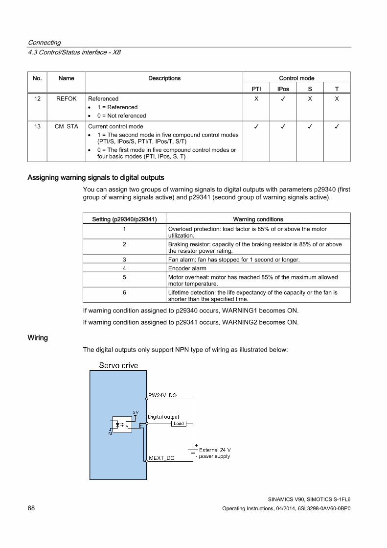
Connecting 4.3 Control/Status interface - X8
SINAMICS V90, SIMOTICS S-1FL6 68 Operating Instructions, 04/2014, 6SL3298-0AV60-0BP0
No. Name Descriptions Control mode
PTI IPos S T 12 REFOK Referenced
• 1 = Referenced • 0 = Not referenced
X ✓ X X
13 CM_STA Current control mode • 1 = The second mode in five compound control modes
(PTI/S, IPos/S, PTI/T, IPos/T, S/T) • 0 = The first mode in five compound control modes or
four basic modes (PTI, IPos, S, T)
✓ ✓ ✓ ✓
Assigning warning signals to digital outputs You can assign two groups of warning signals to digital outputs with parameters p29340 (first group of warning signals active) and p29341 (second group of warning signals active).
Setting (p29340/p29341) Warning conditions
1 Overload protection: load factor is 85% of or above the motor utilization.
2 Braking resistor: capacity of the braking resistor is 85% of or above the resistor power rating.
3 Fan alarm: fan has stopped for 1 second or longer. 4 Encoder alarm 5 Motor overheat: motor has reached 85% of the maximum allowed
motor temperature. 6 Lifetime detection: the life expectancy of the capacity or the fan is
shorter than the specified time.
If warning condition assigned to p29340 occurs, WARNING1 becomes ON.
If warning condition assigned to p29341 occurs, WARNING2 becomes ON.
Wiring The digital outputs only support NPN type of wiring as illustrated below:

Connecting 4.3 Control/Status interface - X8
SINAMICS V90, SIMOTICS S-1FL6 Operating Instructions, 04/2014, 6SL3298-0AV60-0BP0 69
4.3.2 Pulse train inputs/encoder outputs (PTIs/PTOs)
4.3.2.1 PTIs Two channels of pulse train input are available for the SINAMICS V90 servo drive:
● 24 V single end pulse train input
● High-speed 5 V differential pulse train input
When using the 24 V single end PTI: When using the 5 V differential PTI:
Note
Only one channel can be used. The 24 V single end PTI is the factory setting of the SINAMICS V90 servo drives.
When you choose to use the high-speed 5 V differential PTI, you must change the value of parameter p29014 from 1 to 0. Refer to "Selecting a setpoint pulse train input channel (Page 133)".
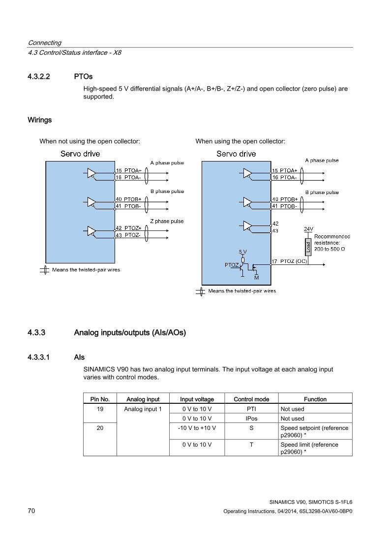
Connecting 4.3 Control/Status interface - X8
SINAMICS V90, SIMOTICS S-1FL6 70 Operating Instructions, 04/2014, 6SL3298-0AV60-0BP0
4.3.2.2 PTOs High-speed 5 V differential signals (A+/A-, B+/B-, Z+/Z-) and open collector (zero pulse) are supported.
Wirings
When not using the open collector: When using the open collector:
4.3.3 Analog inputs/outputs (AIs/AOs)
4.3.3.1 AIs SINAMICS V90 has two analog input terminals. The input voltage at each analog input varies with control modes.
Pin No. Analog input Input voltage Control mode Function
19 Analog input 1 0 V to 10 V PTI Not used 0 V to 10 V IPos Not used
20 -10 V to +10 V S Speed setpoint (reference p29060) *
0 V to 10 V T Speed limit (reference p29060) *
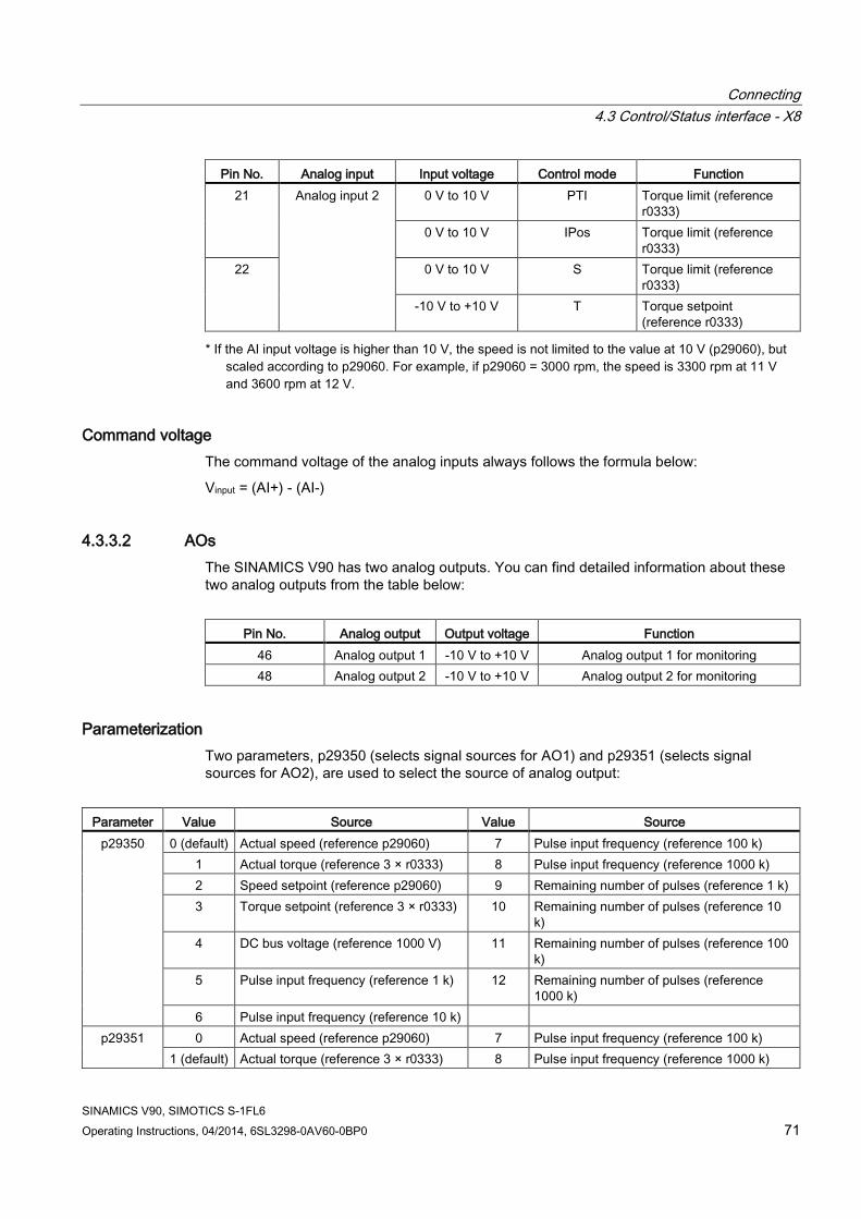
Connecting 4.3 Control/Status interface - X8
SINAMICS V90, SIMOTICS S-1FL6 Operating Instructions, 04/2014, 6SL3298-0AV60-0BP0 71
Pin No. Analog input Input voltage Control mode Function 21 Analog input 2 0 V to 10 V PTI Torque limit (reference
r0333) 0 V to 10 V IPos Torque limit (reference
r0333) 22 0 V to 10 V S Torque limit (reference
r0333) -10 V to +10 V T Torque setpoint
(reference r0333) * If the AI input voltage is higher than 10 V, the speed is not limited to the value at 10 V (p29060), but
scaled according to p29060. For example, if p29060 = 3000 rpm, the speed is 3300 rpm at 11 V and 3600 rpm at 12 V.
Command voltage The command voltage of the analog inputs always follows the formula below:
Vinput = (AI+) - (AI-)
4.3.3.2 AOs The SINAMICS V90 has two analog outputs. You can find detailed information about these two analog outputs from the table below:
Pin No. Analog output Output voltage Function
46 Analog output 1 -10 V to +10 V Analog output 1 for monitoring 48 Analog output 2 -10 V to +10 V Analog output 2 for monitoring
Parameterization Two parameters, p29350 (selects signal sources for AO1) and p29351 (selects signal sources for AO2), are used to select the source of analog output:
Parameter Value Source Value Source
p29350 0 (default) Actual speed (reference p29060) 7 Pulse input frequency (reference 100 k) 1 Actual torque (reference 3 × r0333) 8 Pulse input frequency (reference 1000 k) 2 Speed setpoint (reference p29060) 9 Remaining number of pulses (reference 1 k) 3 Torque setpoint (reference 3 × r0333) 10 Remaining number of pulses (reference 10
k) 4 DC bus voltage (reference 1000 V) 11 Remaining number of pulses (reference 100
k) 5 Pulse input frequency (reference 1 k) 12 Remaining number of pulses (reference
1000 k) 6 Pulse input frequency (reference 10 k)
p29351 0 Actual speed (reference p29060) 7 Pulse input frequency (reference 100 k) 1 (default) Actual torque (reference 3 × r0333) 8 Pulse input frequency (reference 1000 k)

Connecting 4.3 Control/Status interface - X8
SINAMICS V90, SIMOTICS S-1FL6 72 Operating Instructions, 04/2014, 6SL3298-0AV60-0BP0
Parameter Value Source Value Source 2 Speed setpoint (reference p29060) 9 Remaining number of pulses (reference 1 k) 3 Torque setpoint (reference 3 × r0333) 10 Remaining number of pulses (reference 10
k) 4 DC bus voltage (reference 1000 V) 11 Remaining number of pulses (reference 100
k) 5 Pulse input frequency (reference 1 k) 12 Remaining number of pulses (reference
1000 k) 6 Pulse input frequency (reference 10 k)
Wiring Do wiring of analog outputs as follows:

Connecting 4.3 Control/Status interface - X8
SINAMICS V90, SIMOTICS S-1FL6 Operating Instructions, 04/2014, 6SL3298-0AV60-0BP0 73
4.3.4 Standard application wirings (factory setting)
4.3.4.1 Pulse train input position control (PTI) Standard wiring for pulse train input position control mode:

Connecting 4.3 Control/Status interface - X8
SINAMICS V90, SIMOTICS S-1FL6 74 Operating Instructions, 04/2014, 6SL3298-0AV60-0BP0
4.3.4.2 Internal position control (IPos) Standard wiring for internal position control mode:

Connecting 4.3 Control/Status interface - X8
SINAMICS V90, SIMOTICS S-1FL6 Operating Instructions, 04/2014, 6SL3298-0AV60-0BP0 75
4.3.4.3 Speed control (S) Standard wiring for speed control mode:
Note
The analog outputs to analog inputs on the servo unit and the 24V input for the servo unit must use a common ground (M).

Connecting 4.3 Control/Status interface - X8
SINAMICS V90, SIMOTICS S-1FL6 76 Operating Instructions, 04/2014, 6SL3298-0AV60-0BP0
4.3.4.4 Torque control (T) Standard wiring for torque control mode:

Connecting 4.3 Control/Status interface - X8
SINAMICS V90, SIMOTICS S-1FL6 Operating Instructions, 04/2014, 6SL3298-0AV60-0BP0 77
Note
The analog outputs to analog inputs on the servo unit and the 24V input for the servo unit must use a common ground (M).
4.3.5 Connection examples with PLCs This section gives examples of connections between the drive and the PLC. All of the connection examples shown in this section are made based on factory default settings for digital inputs/outputs.

Connecting 4.3 Control/Status interface - X8
SINAMICS V90, SIMOTICS S-1FL6 78 Operating Instructions, 04/2014, 6SL3298-0AV60-0BP0
4.3.5.1 SIMATIC S7-200 SMART ● Pulse train input position control (PTI)
When connect to different axes, the outputs are different. The diagram below take the connection with axis 0 as example.
1) When connect to axis 1, the outputs are DO a.1 and DO a.7;
When connect to axis 2, the outputs are DO a.3 and DO b.0.

Connecting 4.3 Control/Status interface - X8
SINAMICS V90, SIMOTICS S-1FL6 Operating Instructions, 04/2014, 6SL3298-0AV60-0BP0 79
* The resistor R3 (200 to 500 Ohm) is required only if the speed for searching the zero position exceeds 300 rpm.
● Internal position control (IPos)

Connecting 4.3 Control/Status interface - X8
SINAMICS V90, SIMOTICS S-1FL6 80 Operating Instructions, 04/2014, 6SL3298-0AV60-0BP0
● Speed control (S)

Connecting 4.3 Control/Status interface - X8
SINAMICS V90, SIMOTICS S-1FL6 Operating Instructions, 04/2014, 6SL3298-0AV60-0BP0 81
● Torque control (T)

Connecting 4.3 Control/Status interface - X8
SINAMICS V90, SIMOTICS S-1FL6 82 Operating Instructions, 04/2014, 6SL3298-0AV60-0BP0
4.3.5.2 SIMATIC S7-200 ● Pulse train input position control (PTI)
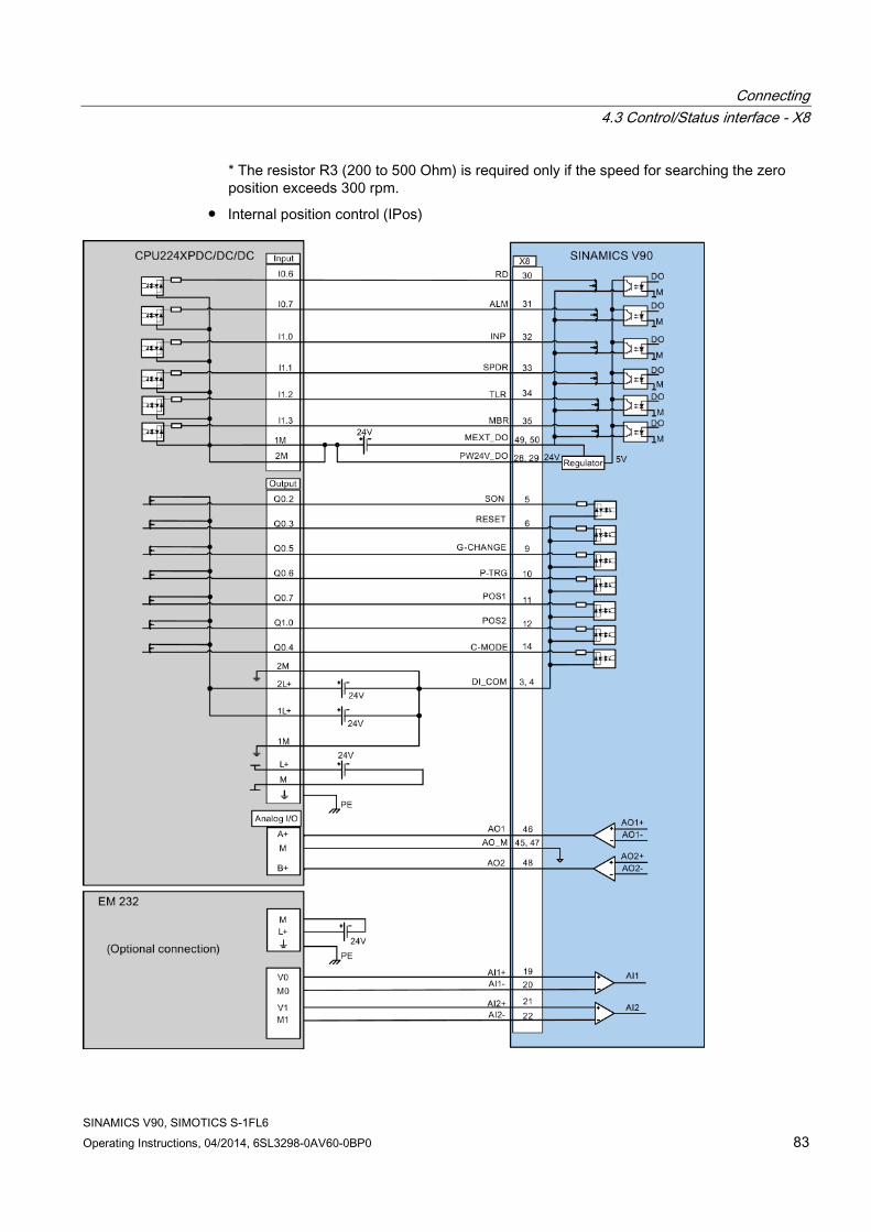
Connecting 4.3 Control/Status interface - X8
SINAMICS V90, SIMOTICS S-1FL6 Operating Instructions, 04/2014, 6SL3298-0AV60-0BP0 83
* The resistor R3 (200 to 500 Ohm) is required only if the speed for searching the zero position exceeds 300 rpm.
● Internal position control (IPos)

Connecting 4.3 Control/Status interface - X8
SINAMICS V90, SIMOTICS S-1FL6 84 Operating Instructions, 04/2014, 6SL3298-0AV60-0BP0
● Speed control (S)

Connecting 4.3 Control/Status interface - X8
SINAMICS V90, SIMOTICS S-1FL6 Operating Instructions, 04/2014, 6SL3298-0AV60-0BP0 85
● Torque control (T)

Connecting 4.3 Control/Status interface - X8
SINAMICS V90, SIMOTICS S-1FL6 86 Operating Instructions, 04/2014, 6SL3298-0AV60-0BP0
4.3.5.3 SIMATIC S7-1200 ● Pulse train input position control (PTI)

Connecting 4.3 Control/Status interface - X8
SINAMICS V90, SIMOTICS S-1FL6 Operating Instructions, 04/2014, 6SL3298-0AV60-0BP0 87
* The resistor R3 (200 to 500 Ohm) is required only if the speed for searching the zero position exceeds 300 rpm.
● Internal position control (IPos)

Connecting 4.3 Control/Status interface - X8
SINAMICS V90, SIMOTICS S-1FL6 88 Operating Instructions, 04/2014, 6SL3298-0AV60-0BP0
● Speed control (S)
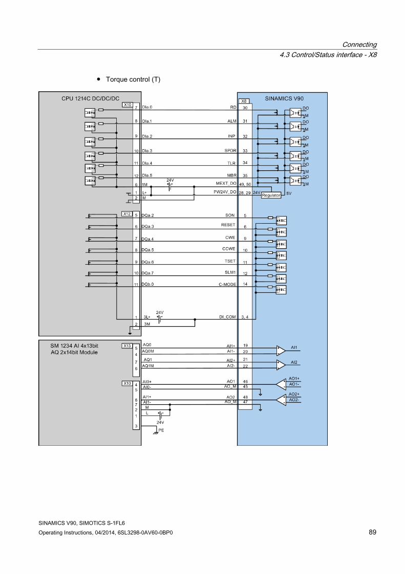
Connecting 4.3 Control/Status interface - X8
SINAMICS V90, SIMOTICS S-1FL6 Operating Instructions, 04/2014, 6SL3298-0AV60-0BP0 89
● Torque control (T)

Connecting 4.4 24V power supply/STO - X6
SINAMICS V90, SIMOTICS S-1FL6 90 Operating Instructions, 04/2014, 6SL3298-0AV60-0BP0
4.4 24V power supply/STO - X6 The pin assignment for the X6 interface is shown as follows:
Interface Signal name Description Remarks
STO 1 Safe torque off channel 1 - STO + Power supply for safe torque off - STO 2 Safe torque off channel 2 - +24 V Power supply, 24 VDC Voltage tolerance:
• Without brake: -15% to +20% • With brake: -10% to +10% Maximum current consumption: • 1.6 A without brake power supply • 3.6 A with brake power supply
M Power supply, 0 VDC
Maximum conductor cross-section: 1.5 mm2
Wiring
WARNING
Material damages and personal injuries by the drop of a vertical axis
When the servo system is used as a vertical axis, the axis will drop if the positive and negative poles of the 24 V power supply are connected inversely. Unexpected drop of the vertical axis may cause material damages and personal injuries.
Make sure that the 24 V power supply is correctly connected.
WARNING
Material damages and personal injuries by the drop of a hanging axis
It is not allowed to use the STO with a hanging axis because the axis may drop. Unexpected drop of the hanging axis may cause material damages and personal injuries.
Note Using the STO function
The STO1, STO+ and STO2 are short connected at the factory setting.
When the STO function is to be used, you must remove the short-circuit stick before connecting the STO interfaces. If you do not need to use it any more, you must reinsert the short-circuit stick; otherwise, the motor will not run.
For detailed information about the STO function, refer to "Safety Integrated basic functions (Page 191)".

Connecting 4.5 Encoder interface - X9
SINAMICS V90, SIMOTICS S-1FL6 Operating Instructions, 04/2014, 6SL3298-0AV60-0BP0 91
Plugging the 24 V power supply and STO cables
4.5 Encoder interface - X9 The SINAMICS V90 servo drive supports two kinds of encoders:
● Incremental encoder
● Absolute encoder
NOTICE
Cable shielding
The encoder cable must be shielded to meet the EMC requirements.

Connecting 4.5 Encoder interface - X9
SINAMICS V90, SIMOTICS S-1FL6 92 Operating Instructions, 04/2014, 6SL3298-0AV60-0BP0
Encoder interface - drive side
Illustration Pin Signal name Description
1 Biss_DataP Absolute encoder data signal, positive 2 Biss_DataN Absolute encoder data signal, negative 3 Biss_ClockN Absolute encoder clock signal, negative 4 Biss_ClockP Absolute encoder clock signal, positive 5 P5V Encoder power supply, +5V 6 P5V Encoder power supply, +5V 7 M Encoder power supply, grounding 8 M Encoder power supply, grounding 9 Rp Encoder R phase positive signal 10 Rn Encoder R phase negative signal 11 Bn Encoder B phase negative signal 12 Bp Encoder B phase positive signal 13 An Encoder A phase negative signal 14 Ap Encoder A phase positive signal
Screw type: UNC 4-40 (plug-in terminal block) Tightening torque: 0.5 - 0.6 Nm
Encoder connector - motor side
Illustration Pin No.
Incremental encoder Absolute encoder
Signal Description Signal Description
1 P_Supply Power supply 5 V P_Supply Power supply 5 V
2 M Power supply 0 V M Power supply 0 V
3 A+ Phase A+ n. c. Not connected 4 A- Phase A- Clock_N Inverted clock 5 B+ Phase B+ Data_P Data 6 B- Phase B- Clock_P Clock 7 R+ Phase R+ n. c. Not connected 8 R- Phase R- Data_N Inverted data

Connecting 4.5 Encoder interface - X9
SINAMICS V90, SIMOTICS S-1FL6 Operating Instructions, 04/2014, 6SL3298-0AV60-0BP0 93
Wiring
Grounding To ensure better EMC effects, you are recommended to strip the encoder cable and connect the cable shield to earth, as shown in the following figure:

Connecting 4.6 External braking resistor - DCP, R1
SINAMICS V90, SIMOTICS S-1FL6 94 Operating Instructions, 04/2014, 6SL3298-0AV60-0BP0
4.6 External braking resistor - DCP, R1 The SINAMICS V90 has been designed with an internal braking resistor to absorb regenerative energy from the motor. When the internal braking resistor cannot meet the braking requirements (e.g. the alarm A52901 is generated), you can connect an external braking resistor. For the selection of braking resistors, refer to Accessories (Page 31).
Connecting an external braking resistor
WARNING
Damage to the drive
Before connecting an external resistor to DCP and R1, remove the short-circuit stick on the connectors. Otherwise, the drive may be damaged.
For the connection of the external braking resistor, refer to System connection (Page 55).
4.7 Motor holding brake - X7 You can connect the SINAMICS V90 servo drive to a servo motor with brake to use the function of motor holding brake.
The relevant information about the interface and wiring is described as follows.
Note Motor holding brake
For detailed information about the function of motor holding brake, refer to the section "Motor holding brake (Page 130)".
Motor holding brake - drive side
Illustration Signal Description
B+ + 24 V, motor brake voltage positive B- 0 V, motor brake voltage negative
Maximum conductor cross-section: 1.5 mm2 Input voltage tolerance: 24 V ± 10%
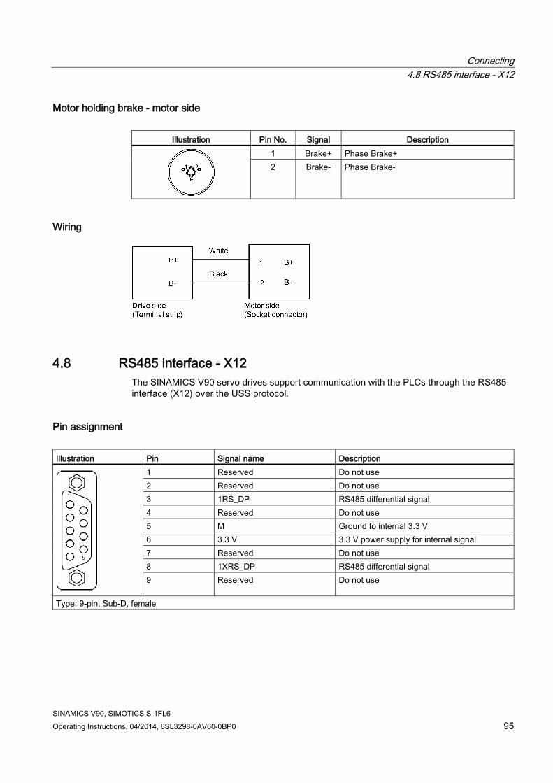
Connecting 4.8 RS485 interface - X12
SINAMICS V90, SIMOTICS S-1FL6 Operating Instructions, 04/2014, 6SL3298-0AV60-0BP0 95
Motor holding brake - motor side
Illustration Pin No. Signal Description
1 Brake+ Phase Brake+ 2 Brake- Phase Brake-
Wiring
4.8 RS485 interface - X12 The SINAMICS V90 servo drives support communication with the PLCs through the RS485 interface (X12) over the USS protocol.
Pin assignment Illustration Pin Signal name Description
1 Reserved Do not use 2 Reserved Do not use 3 1RS_DP RS485 differential signal 4 Reserved Do not use 5 M Ground to internal 3.3 V 6 3.3 V 3.3 V power supply for internal signal 7 Reserved Do not use 8 1XRS_DP RS485 differential signal 9 Reserved Do not use
Type: 9-pin, Sub-D, female

Connecting 4.8 RS485 interface - X12
SINAMICS V90, SIMOTICS S-1FL6 96 Operating Instructions, 04/2014, 6SL3298-0AV60-0BP0

SINAMICS V90, SIMOTICS S-1FL6 Operating Instructions, 04/2014, 6SL3298-0AV60-0BP0 97
Commissioning 5
Prior to commissioning, read "Basic operator panel (BOP) (Page 107)" for more information about the BOP operations. In case of any faults or alarms during commissioning, refer to Chapter "Diagnostics (Page 249)" for detailed description.
CAUTION
Carefully read the safety instructions
Before your commissioning or operation, read Section "General safety instructions (Page 11)" and the safety instructions on "Commissioning/Operation" in Section "Additional safety instructions (Page 16)" carefully. Failure to observe the instructions may cause serious effects.
WARNING
Material damages and personal injuries by the drop of a hanging axis
When the servo system is used as a hanging axis, the axis will drop if the positive and negative poles of the 24 V power supply are connected inversely. Unexpected drop of the hanging axis may cause material damages and personal injuries.
Before commissioning, a crosstie must be used to hold the hanging axis in prevention of an unexpected drop. In addition, make sure that the 24 V power supply is correctly connected.
NOTICE
Plugging or unplugging the SD card will cause startup failure.
Do not plug or unplug the SD card during startup; otherwise, the drive will fail to start up.
NOTICE
Existing setting data may be overwritten by the setting data on the SD card during startup. • When a drive is switched on with an SD card containing user setting data, the existing
setting data on the drive will be overwritten. • When a drive is switched on with an SD card containing no user setting data, the drive
will automatically save the existing user setting data onto the SD card.
Before starting up the drive with an SD card, check whether the SD card contains user setting data. Otherwise, the existing data on the drive may be overwritten.
Engineering tool - SINAMICS V-ASSISTANT You can use the engineering tool SINAMICS V-ASSISTANT to perform the trial operation.
SINAMICS V-ASSISTANT is a software tool that can be installed on a PC and runs on the Windows operating system. It communicates with the SINAMICS V90 servo drive with a USB

Commissioning 5.1 Initial commissioning in JOG mode
SINAMICS V90, SIMOTICS S-1FL6 98 Operating Instructions, 04/2014, 6SL3298-0AV60-0BP0
cable. With SINAMICS V-ASSISTANT, you can change drive parameters and monitor drive working states in online mode.
For more information, refer to SINAMICS V-ASSISTANT Online Help. You can search and download SINAMICS V-ASSISTANT from Technical support website (http://support.automation.siemens.com).
5.1 Initial commissioning in JOG mode
Commissioning purpose When the servo drive is powered on for the first time, you can perform a test run with the BOP or the engineering tool SINAMICS V-ASSISTANT to check:
● Whether the mains supply has been connected correctly
● Whether the 24 V power supply has been connected correctly
● Whether the cables (power cable, encoder cable, and brake cable) between the servo drive and the servo motor have been connected correctly
● Whether the motor speed and direction of rotation are correct.
Prerequisites ● The servo drive is connected to the servo motor without load.
● No PLC is connected to the drive system.
Operating sequence
Note
The digital signal EMGS must be kept at high level (1) to ensure normal operation.

Commissioning 5.1 Initial commissioning in JOG mode
SINAMICS V90, SIMOTICS S-1FL6 Operating Instructions, 04/2014, 6SL3298-0AV60-0BP0 99
Step Description Remarks
1 Connect necessary units and check wiring. It is necessary to connect the following cables: • Power cable • Encoder cable • Brake cable • Line supply cable • 24 VDC cable Check: • Is the device or cable damaged? • Do the connected cables have excessive pressure,
load or tension? • Are the connected cables put on sharp edges? • Is the line supply within the permissible range? • Are all the terminals firmly and correctly connected? • Are all the connected system components well
grounded? Refer to "Connecting (Page 55)".
2 Switch on the 24 V power supply. 3 Check the servo motor type.
• If the servo motor has an incremental encoder, input motor ID (p29000).
• If the servo motor has an absolute encoder, the servo drive can identify the servo motor automatically.
Fault F52984 occurs when the servo motor is not identified. You can find the motor ID from the motor rating plate. Go to "Motor components (Page 25)" for detailed descriptions about motor rating plate. Refer to "Basic operations (Page 113)" for information about how to change a parameter with the BOP.
4 Check the direction of motor rotation. The default direction of rotation is CW (clockwise). You can change it by setting the parameter p29001 if necessary.
p29001=0: CW p29001=1: CCW
5 Check the Jog speed. The default Jog speed is 100 rpm. You can change it by setting the parameter p1058.
6 Save parameters. For detailed information about the parameter setting / saving with the BOP, refer to the sections "Basic operations (Page 113)" or "Saving parameters (RAM to ROM) (Page 119)".
7 Clear faults and alarms. Refer to "Diagnostics (Page 249)". 8 For the BOP, enter the Jog menu function and press the
UP or DOWN button to run the servo motor. For the engineering tool, use the Jog function to run the servo motor.
For detailed information about Jog with the BOP, refer to Section "Jog (Page 118)". For detailed information about Jog with SINAMICS V-ASSISTANT, refer to SINAMICS V-ASSISTANT Online Help.

Commissioning 5.2 Commissioning in pulse train position control mode (PTI)
SINAMICS V90, SIMOTICS S-1FL6 100 Operating Instructions, 04/2014, 6SL3298-0AV60-0BP0
Note
When you run the servo motor with an incremental encoder in JOG mode, the servo motor makes a short buzzing sound indicating that it is identifying the magnetic pole position of the rotor.
5.2 Commissioning in pulse train position control mode (PTI)
Step Description Comment 1 Switch off the mains supply. 2 Power off the servo drive and connect it to the controller (for
example, SIMATIC S7-200 SMART) with the signal cable. The digital signals CWL, CCWL and EMGS must be kept at high level (1) to ensure normal operation. Refer to "Standard application wirings (factory setting) (Page 73)" and "Connection examples with PLCs (Page 77)".
3 Power on the servo drive. 4 Check current control mode by viewing value of the parameter
p29003. Pulse train input position control mode (p29003=0) is the factory setting of SINAMICS V90 servo drives.
Refer to "Compound controls (Page 125)".
5 Configure necessary digital input signals by setting the following parameters: • p29301[0]: DI1 • p29302[0]: DI2 • p29303[0]: DI3 • p29304[0]: DI4 • p29305[0]: DI5 • p29306[0]: DI6 • p29307[0]: DI7 • p29308[0]: DI8
The factory settings are: • p29301[0]: 1 (SON) • p29302[0]: 2 (RESET) • p29303[0]: 3 (CWL) • p29304[0]: 4 (CCWL) • p29305[0]: 5 (G-CHANGE) • p29306[0]: 6 (P-TRG) • p29307[0]: 7 (CLR) • p99308[0]: 10 (TLIM1) Refer to "Digital inputs/outputs (DIs/DOs) (Page 61)".
6 Select a pulse input channel by setting parameter p29014. • p29014=0: high-speed 5 V differential pulse train input
• p29014=1: 24 V single end pulse train input
24 V single end pulse train input is the factory setting. Refer to "Selecting a setpoint pulse train input channel (Page 133)".

Commissioning 5.3 Commissioning in internal position control mode (IPos)
SINAMICS V90, SIMOTICS S-1FL6 Operating Instructions, 04/2014, 6SL3298-0AV60-0BP0 101
Step Description Comment 7 Select a setpoint pulse train input form by setting parameter
p29010. • p29010=0: pulse + direction, positive logic • p29010=1: AB track, positive logic • p29010=2: pulse + direction, negative logic • p29010=3: AB track, negative logic The factory setting is p29010=0 (pulse + direction, positive logic). Refer to "Selecting a setpoint pulse train input form (Page 133)".
8 Calculate the electronic gear ratio, then input values into parameters p29011, p29012, and p29013.
• p29011: number of setpoint pulses per revolution.
• p29012: numerator of the electronic gear. Four numerators in total (p29012[0] to p29012[3]) are available.
• p29013: denominator of the electronic gear.
Refer to "Electronic gear ratio (Page 136)". 9 Check the encoder type.
If it is an absolute encoder, adjust the absolute encoder with the BOP menu function "ABS".
Refer to "Adjusting an absolute encoder (Page 124)".
10 Clear faults and alarms. Refer to "Diagnostics (Page 249)". 11 Trigger SON to the high level, input the setpoint pulse train from
the command device, and then the servo motor starts running. Use a low pulse frequency at first to check the direction and speed of rotation.
12 The system commissioning in pulse train input position control mode ends.
You can check the system performance. If it is not ok, you can adjust it. Refer to "Tuning (Page 195)".
5.3 Commissioning in internal position control mode (IPos)
Step Description Remarks 1 Switch off the mains supply. 2 Power off the servo drive and connect it to the controller (for
example, SIMATIC S7-200 SMART) with the signal cable. The digital signals CWL, CCWL and EMGS must be kept at high level (1) to ensure normal operation. Refer to "Standard application wirings (factory setting) (Page 73)" and "Connection examples with PLCs (Page 77)".
3 Power on the servo drive. 4 Switch to the internal position control mode by setting p29003=1. Refer to "Compound controls (Page 125)". 5 Save the parameter and restart the servo drive to apply the settings
of the internal position control mode.

Commissioning 5.3 Commissioning in internal position control mode (IPos)
SINAMICS V90, SIMOTICS S-1FL6 102 Operating Instructions, 04/2014, 6SL3298-0AV60-0BP0
Step Description Remarks 6 Configure necessary digital input signals by setting the following
parameters: • p29301[1]: DI1 • p29302[1]: DI2 • p29303[1]: DI3 • p29304[1]: DI4 • p29305[1]: DI5 • p29306[1]: DI6 • p29307[1]: DI7 • p29308[1]: DI8
The factory settings are: • p29301[1]: 1 (SON) • p29302[1]: 2 (RESET) • p29303[1]: 3 (CWL) • p29304[1]: 4 (CCWL) • p29305[1]: 5 (G-CHANGE) • p29306[1]: 6 (P-TRG) • p29307[1]: 21 (POS1) • p29308[1]: 22 (POS2) Refer to "Digital inputs/outputs (DIs/DOs) (Page 61)". NOTE: If your encoder is an incremental encoder, you must configure the digital input signal REF or SREF according to your selection of referencing mode. Refer to "Referencing (Page 151)".
7 Configure the fixed position setpoint (p2617[0] to p2617[7]) according to mechanism.
• Fixed position setpoint 1: p2617[0] • Fixed position setpoint 2: p2617[1] • Fixed position setpoint 3: p2617[2] • Fixed position setpoint 4: p2617[3] • Fixed position setpoint 5: p2617[4] • Fixed position setpoint 6: p2617[5] • Fixed position setpoint 7: p2617[6] • Fixed position setpoint 8: p2617[7] Refer to "Setting fixed position setpoint (Page 147)".
8 Check and select a positioning mode by setting parameter p29241. • p29241=0: incremental • p29241=1: absolute • p29241=2: absolute, positive (only for a
rotary axis with modulo correction) • p29241=3: absolute, negative (only for a
rotary axis with modulo correction) Refer to "Selecting a positioning mode - absolute/incremental (Page 149)".

Commissioning 5.4 Commissioning in speed control mode (S)
SINAMICS V90, SIMOTICS S-1FL6 Operating Instructions, 04/2014, 6SL3298-0AV60-0BP0 103
Step Description Remarks 9 Check the encoder type and perform referencing:
• For an incremental encoder, choose a referencing mode by setting parameter p29240 and perform referencing.
• For an absolute encoder, adjust the encoder with the BOP menu function "ABS". Refer to "Adjusting an absolute encoder (Page 124)".
Five referencing modes are available for the incremental encoder: • p29240=0: with digital input signal REF • p29240=1 (default): external referencing
cam (REF) and encoder zero mark • p29240=2: only encoder zero mark • p29240=3: external referencing cam
(CCWL) and encoder zero mark • p29240=4: external referencing cam
(CWL) and encoder zero mark. Refer to "Referencing (Page 151)".
10 Clear faults and alarms. Refer to "Diagnostics (Page 249)". 11 Trigger the digital signal SON to be high level. 12 Select a fixed position setpoint by configuring the digital inputs
POS1, POS2 and POS3, then start positioning with the triggering signal P-TRG.
POS3 : POS2 : POS1 0 : 0 : 0: fixed position setpoint 1 (p2617[0]) 0 : 0 : 1: fixed position setpoint 2 (p2617[1]) 0 : 1 : 0: fixed position setpoint 3 (p2617[2]) 0 : 1 : 1: fixed position setpoint 4 (p2617[3]) 1 : 0 : 0: fixed position setpoint 5 (p2617[4]) 1 : 0 : 1: fixed position setpoint 6 (p2617[5]) 1 : 1 : 0: fixed position setpoint 7 (p2617[6]) 1 : 1 : 1: fixed position setpoint 8 (p2617[7]) Refer to "Selecting a fixed position setpoint and starting positioning (Page 160)".
13 The system commissioning in internal position control mode ends. You can check the system performance. If it is not ok, you can adjust it. Refer to "Tuning (Page 195)".
5.4 Commissioning in speed control mode (S)
Step Description Remarks 1 Switch off the mains supply. 2 Power off the servo drive and connect it to the controller (for
example, SIMATIC S7-200 SMART) with the signal cable. The digital signals CWL, CCWL and EMGS must be kept at high level (1) to ensure normal operation. Refer to "Standard application wirings (factory setting) (Page 73)" and "Connection examples with PLCs (Page 77)".
3 Power on the servo drive. 4 Switch to the speed control mode by setting p29003=2. Refer to "Compound controls (Page 125)". 5 Restart the servo drive to apply the settings of the speed
control mode.

Commissioning 5.4 Commissioning in speed control mode (S)
SINAMICS V90, SIMOTICS S-1FL6 104 Operating Instructions, 04/2014, 6SL3298-0AV60-0BP0
Step Description Remarks 6 Configure necessary digital input signals by setting the
following parameters: • p29301[2]: DI1 • p29302[2]: DI2 • p29303[2]: DI3 • p29304[2]: DI4 • p29305[2]: DI5 • p29306[2]: DI6 • p29307[2]: DI7 • p29308[2]: DI8
The factory settings are: • p29301[2]: 1 (SON) • p29302[2]: 2 (RESET) • p29303[2]: 3 (CWL) • p29304[2]: 4 (CCWL) • p29305[2]: 12 (CWE) • p29306[2]: 13 (CCWE) • p29307[2]: 15 (SPD1) • p29308[2]: 16 (SPD2) Refer to "Digital inputs/outputs (DIs/DOs) (Page 61)".
7 Configure speed setpoint. You can select the external analog speed setpoint or one of seven fixed speed setpoints by configuring the digital signals SPD3, SPD2 and SPD1. SPD3 : SPD2 : SPD1 0 : 0 : 0: external analog speed setpoint (analog input 1) 0 : 0 : 1: fixed speed setpoint 1 (p1001) 0 : 1 : 0: fixed speed setpoint 2 (p1002) 0 : 1 : 1: fixed speed setpoint 3 (p1003) 1 : 0 : 0: fixed speed setpoint 4 (p1004) 1 : 0 : 1: fixed speed setpoint 5 (p1005) 1 : 1 : 0: fixed speed setpoint 6 (p1006) 1 : 1 : 1: fixed speed setpoint 7 (p1007) Refer to "Configuring speed setpoint (Page 162)".
8 If the external analog speed setpoint is used, configure the maximum analog speed setpoint corresponding to 10 V by setting parameter p29060.
9 Clear faults and alarms. Refer to "Diagnostics (Page 249)". 10 Change SON status to be high level (1) and the servo motor
starts running according to configured speed setpoint. The actual speed of the servo motor can be viewed from the BOP operating display. The default display is the actual speed. Refer to "Actual status display (Page 112)".
11 The system commissioning in speed control mode ends. You can check the system performance. If it is not ok, you can adjust it. Refer to "Tuning (Page 195)".

Commissioning 5.5 Commissioning in torque control mode (T)
SINAMICS V90, SIMOTICS S-1FL6 Operating Instructions, 04/2014, 6SL3298-0AV60-0BP0 105
5.5 Commissioning in torque control mode (T)
Step Description Remarks 1 Switch off the mains supply. 2 Power off the servo drive and connect it to the controller (for
example, SIMATIC S7-200 SMART) with the signal cable. The digital signals CWL, CCWL and EMGS must be kept at high level (1) to ensure normal operation. Refer to "Standard application wirings (factory setting) (Page 73)" and "Connection examples with PLCs (Page 77)".
3 Power on the servo drive. 4 Switch to the torque control mode by setting p29003=3. Refer to "Compound controls (Page 125)". 5 Restart the servo drive to apply the settings of the torque
control mode.
6 Configure necessary digital input signals by setting the following parameters: • p29301[3]: DI1 • p29302[3]: DI2 • p29303[3]: DI3 • p29304[3]: DI4 • p29305[3]: DI5 • p29306[3]: DI6 • p29307[3]: DI7 • p29308[3]: DI8
The factory settings are: • p29301[3]: 1 (SON) • p29302[3]: 2 (RESET) • p29303[3]: 3 (CWL) • p29304[3]: 4 (CCWL) • p29305[3]: 12 (CWE) • p29306[3]: 13 (CCWE) • p29307[3]: 18 (TSET) • p29308[3]: 19 (SLIM1) Refer to "Digital inputs/outputs (DIs/DOs) (Page 61)".
7 Select torque setpoint by configuring the digital input signal TSET.
• TSET = low level (0): external analog torque setpoint (analog input 2)
• TSET = high level (1): fixed torque setpoint
8 If the external analog torque setpoint is used, configure the scaling (percentage of the rated torque) for analog torque setpoint corresponding to 10 V by setting parameter p29041[0].
Refer to "Torque control with external analog torque setpoint (Page 170)".
9 If the fixed torque setpoint is used, input your desired torque setpoint value into parameter p29043.
Refer to "Torque control with fixed torque setpoint (Page 171)".
10 Clear faults and alarms. Refer to "Diagnostics (Page 249)". 11 Change SON status to be high level (1) and the servo motor
starts running according to configured torque setpoint. The actual torque of the servo motor can be viewed from the BOP operating display. The default display is actual speed. You can change it by setting p29002=2. Refer to "Actual status display (Page 112)".
12 The system commissioning in torque control mode ends. You can check the system performance. If it is not ok, you can adjust it. Refer to "Tuning (Page 195)".

Commissioning 5.5 Commissioning in torque control mode (T)
SINAMICS V90, SIMOTICS S-1FL6 106 Operating Instructions, 04/2014, 6SL3298-0AV60-0BP0

SINAMICS V90, SIMOTICS S-1FL6 Operating Instructions, 04/2014, 6SL3298-0AV60-0BP0 107
Basic operator panel (BOP) 6 6.1 BOP overview
The SINAMICS V90 servo drive is designed with a Basic Operator Panel (BOP) on the front panel of the servo drive:
Figure 6-1 BOP overview
You can use the BOP for the following operations:
● Standalone commissioning
● Diagnosis
● Parameter access
● Parameter settings
● SD card operations
● Drive restart
6.1.1 BOP display
Display Example Description Remarks 8.8.8.8.8.8.
Drive is in startup state
------
Drive is busy

Basic operator panel (BOP) 6.1 BOP overview
SINAMICS V90, SIMOTICS S-1FL6 108 Operating Instructions, 04/2014, 6SL3298-0AV60-0BP0
Display Example Description Remarks Fxxxxx
Fault code In the case of a single fault
F.xxxxx.
Fault code of the first fault In the case of multiple faults
Fxxxxx.
Fault code In the case of multiple faults
Axxxxx
Alarm code In the case of a single alarm
A.xxxxx.
Alarm code of the first alarm In the case of multiple alarms
Axxxxx.
Alarm code In the case of multiple alarms
Rxxxxx
Parameter number Read-only parameter
Pxxxxx
Parameter number Editable parameter
P.xxxxx
Parameter number Editable parameter; the dot means that at least one parameter has been changed
In xx
Indexed parameter Figure after "In" indicates the number of indices. For example, "In 01" means that this indexed parameter is 1.
xxx.xxx
Negative parameter value
xxx.xx<>
Current display can be moved to left or right
xxxx.xx>
Current display can be moved to right
xxxx.xx<
Current display can be moved to left
S Off
Operating display: servo off
Para
Editable parameter group Refer to the section "Change a parameter value (Page 113)".
P 0x
Parameter group Six groups are available: 1. P0A: basic 2. P0B: gain adjustment 3. P0C: speed control 4. P0D: torque control 5. P0E: position control 6. P0F: IO
Data
Read-only parameter group Refer to "Read a parameter value (Page 116)".
Func
Function group Refer to "Function overview (Page 117)".
Jog
Jog function Refer to "Jog (Page 118)".

Basic operator panel (BOP) 6.1 BOP overview
SINAMICS V90, SIMOTICS S-1FL6 Operating Instructions, 04/2014, 6SL3298-0AV60-0BP0 109
Display Example Description Remarks Save
Save data in drive Refer to "Save parameters in the servo drive
(Page 119)". defu
Restore drive to default settings Refer to "Reset parameters to default values
(Page 119)". dr--sd
Save data from drive to SD card Refer to "Copy parameters from the servo
drive to an SD card (Page 120)". sd--dr
Upload data from SD card to drive Refer to "Copy parameters from an SD card
to the servo drive (Page 121)". Update
Update firmware Refer to "Update firmware (Page 122)".
A OFF1
Adjust AI1 offset Refer to "Adjust AI offset (Page 122)".
A OFF2
Adjust AI2 offset Refer to "Adjust AI offset (Page 122)".
ABS
The zero position has not been set Refer to "Set zero position (Page 124)".
A.B.S.
The zero position has been set Refer to "Set zero position (Page 124)".
r xxx
Actual speed (positive direction)
r -xxx
Actual speed (negative direction)
T x.x
Actual torque (positive direction)
T -x.x
Actual torque (negative direction)
DCxxx.x
Actual DC link voltage
Con
The communication between the SINAMICS V-ASSISTANT and the servo drive is established. In this case, the BOP is protected from any operations except clearing alarms and acknowledging faults.

Basic operator panel (BOP) 6.1 BOP overview
SINAMICS V90, SIMOTICS S-1FL6 110 Operating Instructions, 04/2014, 6SL3298-0AV60-0BP0
6.1.2 Control buttons
Button Description Functions
M button • Exits from the current menu • Switches between operating modes in the top level
menu
OK button Short-pressing: • Confirms selection or input • Enters sub menu • Acknowledges faults Long-pressing: Activates auxiliary functions • Sets Drive Bus address • Jog • Saves parameter set in drive (RAM to ROM) • Sets parameter set to default • Transfers data (drive to SD card) • Transfers data (SD card to drive) • Updates firmware
UP button • Navigates to the next item • Increases a value • JOG in CW (clockwise)
DOWN button • Navigates to the previous item • Decreases a value • JOG in CCW (counter-clockwise)
SHIFT button Moves the cursor from digit to digit for single digit editing, including the digit of positive/negative sign Note: When the sign is edited, "_" indicates positive and "-" indicates negative.
Press the key combination for four seconds to restart the drive
Moves current display to the left page when is displayed at the upper right corner, for example .
Moves current display to the right page when is displayed at the lower right corner, for example .
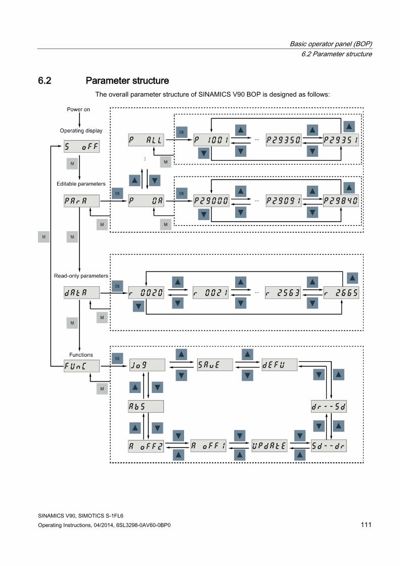
Basic operator panel (BOP) 6.2 Parameter structure
SINAMICS V90, SIMOTICS S-1FL6 Operating Instructions, 04/2014, 6SL3298-0AV60-0BP0 111
6.2 Parameter structure The overall parameter structure of SINAMICS V90 BOP is designed as follows:
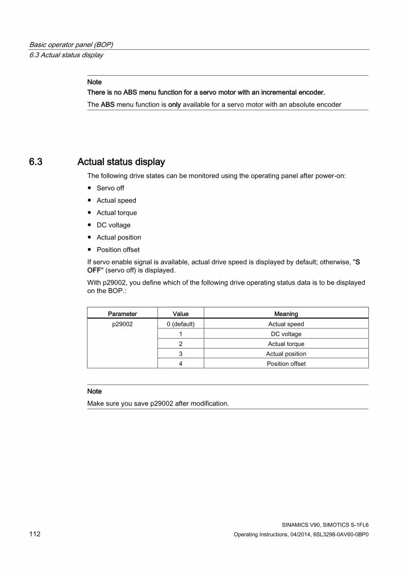
Basic operator panel (BOP) 6.3 Actual status display
SINAMICS V90, SIMOTICS S-1FL6 112 Operating Instructions, 04/2014, 6SL3298-0AV60-0BP0
Note There is no ABS menu function for a servo motor with an incremental encoder.
The ABS menu function is only available for a servo motor with an absolute encoder
6.3 Actual status display The following drive states can be monitored using the operating panel after power-on:
● Servo off
● Actual speed
● Actual torque
● DC voltage
● Actual position
● Position offset
If servo enable signal is available, actual drive speed is displayed by default; otherwise, "S OFF" (servo off) is displayed.
With p29002, you define which of the following drive operating status data is to be displayed on the BOP.:
Parameter Value Meaning
p29002 0 (default) Actual speed 1 DC voltage 2 Actual torque 3 Actual position 4 Position offset
Note
Make sure you save p29002 after modification.

Basic operator panel (BOP) 6.4 Basic operations
SINAMICS V90, SIMOTICS S-1FL6 Operating Instructions, 04/2014, 6SL3298-0AV60-0BP0 113
6.4 Basic operations
Overview ● Editable parameters: all P parameters under the "Para" menu are settable parameters.
Seven groups in total are available:
– P0A: basic
– P0B: gain adjustment
– P0C: speed control
– P0D: torque control
– P0E: position control
– P0F: IO
– P All: all parameters
● Read-only parameters: All r parameters under the "Data" menu are read-only parameters. You can only read values of these parameters.
Parameters with index Some parameters have several indices. Each index has its own meaning and corresponding value.
Parameters without index All parameters that do not have indices are parameters without index.
6.4.1 Editing parameters You can edit a parameter value in two methods:
● Method 1: change the value directly with the UP or DOWN button
● Method 2: move the cursor to a digit with the SHIFT button, then change the digit value with the UP or DOWN button

Basic operator panel (BOP) 6.4 Basic operations
SINAMICS V90, SIMOTICS S-1FL6 114 Operating Instructions, 04/2014, 6SL3298-0AV60-0BP0
If you edit a parameter value with Method 1, proceed as follows:

Basic operator panel (BOP) 6.4 Basic operations
SINAMICS V90, SIMOTICS S-1FL6 Operating Instructions, 04/2014, 6SL3298-0AV60-0BP0 115
To edit a parameter value with Method 2, proceed as follows:
NOTICE
It is forbidden to use this function when the servo is ON.
Use this function when the servo is OFF.
Note
The parameters p1414 and p1656 cannot be changed using the SHIFT button.
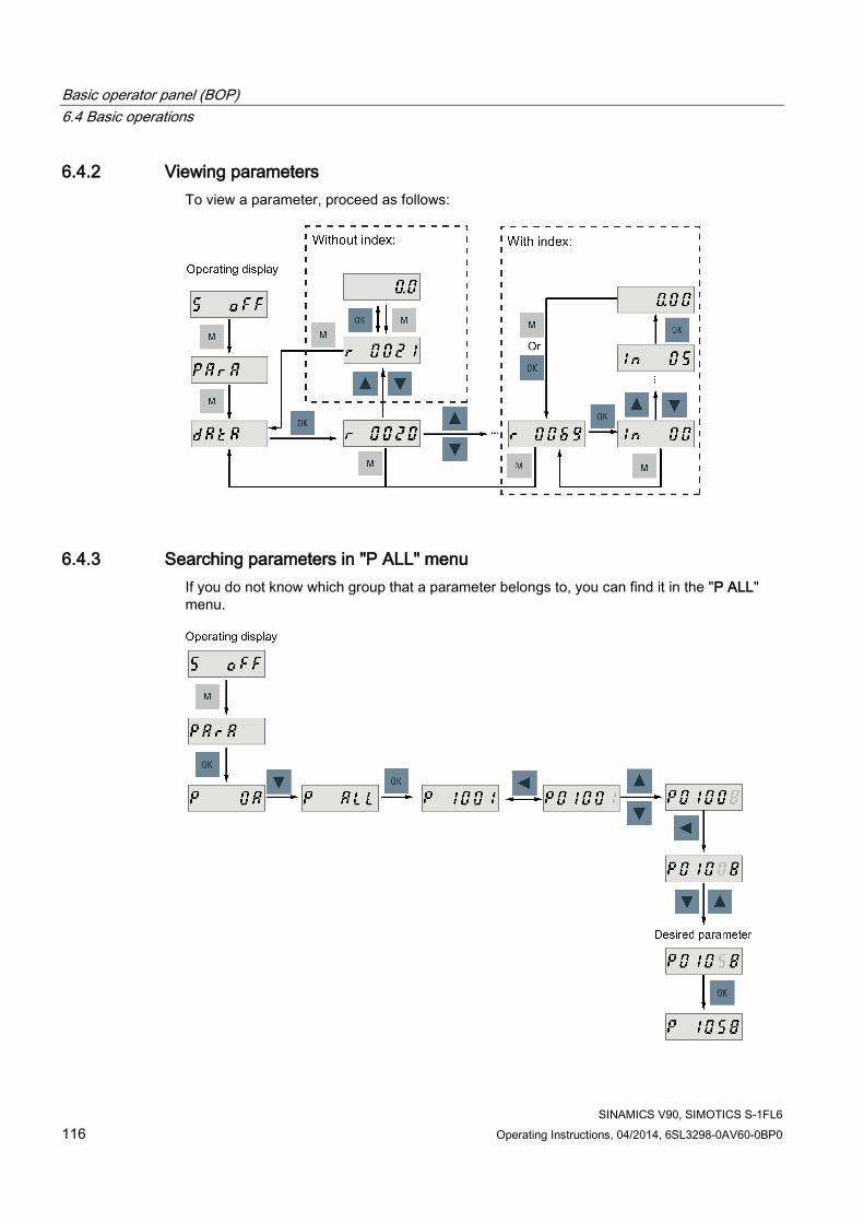
Basic operator panel (BOP) 6.4 Basic operations
SINAMICS V90, SIMOTICS S-1FL6 116 Operating Instructions, 04/2014, 6SL3298-0AV60-0BP0
6.4.2 Viewing parameters To view a parameter, proceed as follows:
6.4.3 Searching parameters in "P ALL" menu If you do not know which group that a parameter belongs to, you can find it in the "P ALL" menu.

Basic operator panel (BOP) 6.5 Auxiliary functions
SINAMICS V90, SIMOTICS S-1FL6 Operating Instructions, 04/2014, 6SL3298-0AV60-0BP0 117
Note Invalid parameter number
If the input parameter number is unavailable, the nearest parameter number to the input value is displayed.
6.5 Auxiliary functions In total, there are 9 BOP functions available:
Figure 6-2 Overview of SINAMICS V90 BOP functions
① Jog ⑥ Update firmware
② Save parameter set in drive ⑦ Adjust AI1 offset
③ Restore parameter values to default ⑧ Adjust AI2 offset
④ Copy parameter set from drive to an SD card
⑨ Adjust absolute encoder NOTE: This function is available only when the servo motor with an absolute encoder is connected.
⑤ Copy parameter set from an SD card to drive

Basic operator panel (BOP) 6.5 Auxiliary functions
SINAMICS V90, SIMOTICS S-1FL6 118 Operating Instructions, 04/2014, 6SL3298-0AV60-0BP0
6.5.1 Jog
Note
The digital signal EMGS must be kept at high level (1) to ensure normal operation.
The travel limit signals (CWL/CCWL) are disabled during Jog operation with the BOP.
With the Jog function, you can run the connected motor and view Jog speed or Jog torque.
To run the connected motor with the Jog function and view the Jog speed, proceed as follows:
Figure 6-3 Jog in speed (example)
To run the connected motor with the Jog function and view the Jog torque, proceed as follows:
Figure 6-4 Jog in torque (example)
NOTICE
Exit the Jog mode after completing Jog run.
The servo motor cannot run if the servo drive is in the Jog mode.

Basic operator panel (BOP) 6.5 Auxiliary functions
SINAMICS V90, SIMOTICS S-1FL6 Operating Instructions, 04/2014, 6SL3298-0AV60-0BP0 119
6.5.2 Saving parameters (RAM to ROM) This function is used for saving a parameter set from the drive RAM to drive ROM.
To use this function, proceed as follows:
NOTICE
Plugging or unplugging the SD card will cause saving failure.
Do not plug or unplug the SD card during saving; otherwise, the saving operation will fail.
Note • If an SD card has been inserted, the parameter set will be saved onto the SD card
simultaneously. • All signal functions become inactive during the saving process. Use the signal functions
afterwards.
Reference Editing parameters (Page 113)
6.5.3 Setting parameters to default This function is used to reset all parameters to their default values.

Basic operator panel (BOP) 6.5 Auxiliary functions
SINAMICS V90, SIMOTICS S-1FL6 120 Operating Instructions, 04/2014, 6SL3298-0AV60-0BP0
To reset the parameters to their default values, proceed as follows:
Note
You must save the parameter set after setting the parameter set to the default values; otherwise, the default values will not be activated.
Reference Saving parameters (RAM to ROM) (Page 119)
6.5.4 Transferring data (drive to SD) You can save the parameter set to an SD card with the BOP. To do this, proceed as follows:
NOTICE
It is forbidden to use this function when the servo is ON.
Use this function when the servo is OFF.

Basic operator panel (BOP) 6.5 Auxiliary functions
SINAMICS V90, SIMOTICS S-1FL6 Operating Instructions, 04/2014, 6SL3298-0AV60-0BP0 121
NOTICE
Plugging or unplugging the SD card will cause copying failure.
Do not plug or unplug the SD card during copying; otherwise, the copying operation will fail.
Note
Write protection function is not supported by SINAMICS V90. Data in the SD card will be overwritten even if the write protection function of the SD card is enabled.
6.5.5 Transferring data (SD to drive) You can also upload the parameters from an SD card to the servo drive. To do this, proceed as follows:
NOTICE
It is forbidden to use this function when the servo is ON.
Use this function when the servo is OFF.
NOTICE
Plugging or unplugging the SD card will cause copying failure.
Do not plug or unplug the SD card during copying; otherwise, the copying operation will fail.
Note Parameter inconsistency
If the parameters on the SD card are inconsistent with existing parameters in the drive memory, you must restart the servo drive to apply the changes.
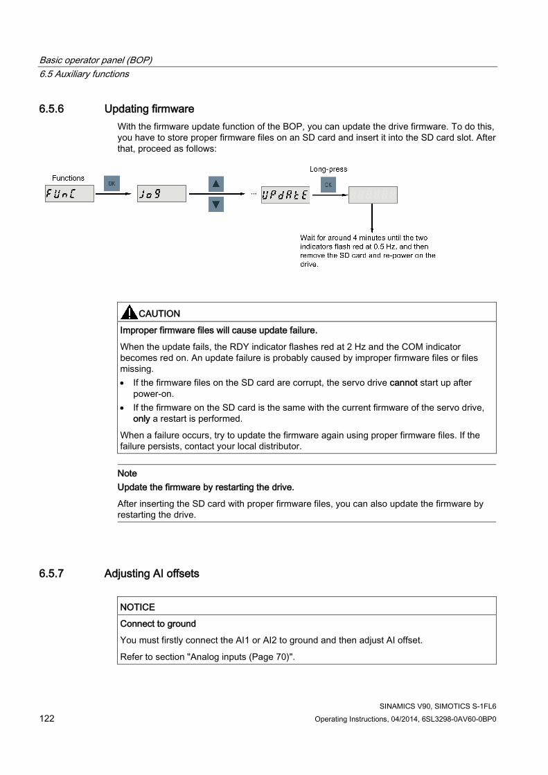
Basic operator panel (BOP) 6.5 Auxiliary functions
SINAMICS V90, SIMOTICS S-1FL6 122 Operating Instructions, 04/2014, 6SL3298-0AV60-0BP0
6.5.6 Updating firmware With the firmware update function of the BOP, you can update the drive firmware. To do this, you have to store proper firmware files on an SD card and insert it into the SD card slot. After that, proceed as follows:
CAUTION
Improper firmware files will cause update failure.
When the update fails, the RDY indicator flashes red at 2 Hz and the COM indicator becomes red on. An update failure is probably caused by improper firmware files or files missing. • If the firmware files on the SD card are corrupt, the servo drive cannot start up after
power-on. • If the firmware on the SD card is the same with the current firmware of the servo drive,
only a restart is performed.
When a failure occurs, try to update the firmware again using proper firmware files. If the failure persists, contact your local distributor.
Note Update the firmware by restarting the drive.
After inserting the SD card with proper firmware files, you can also update the firmware by restarting the drive.
6.5.7 Adjusting AI offsets
NOTICE
Connect to ground
You must firstly connect the AI1 or AI2 to ground and then adjust AI offset.
Refer to section "Analog inputs (Page 70)".

Basic operator panel (BOP) 6.5 Auxiliary functions
SINAMICS V90, SIMOTICS S-1FL6 Operating Instructions, 04/2014, 6SL3298-0AV60-0BP0 123
With the BOP function menu "A OFF1" or "A OFF2", AI offset can be adjusted automatically. Proceed as follows to adjust AI offset:
● Adjust AI1 offset
● Adjust AI2 offset
Note Save parameter
Offset value is set into parameter p29042 (for AI1) or parameter p29061 (for AI2). You must perform parameter saving after the automatic adjustment of AI offset. Parameter range
p29042 or p29061 ranges from -0.5 V to + 0.5 V. A value that is out of this range causes an alarm.
Refer to chapter "Parameter list (Page 217)".

Basic operator panel (BOP) 6.5 Auxiliary functions
SINAMICS V90, SIMOTICS S-1FL6 124 Operating Instructions, 04/2014, 6SL3298-0AV60-0BP0
6.5.8 Adjusting an absolute encoder
NOTICE
Motor type
This function is only available when you are using a servo motor with the absolute encoder. Stop servo motor
You must stop servo motor before adjusting absolute encoder.
With the BOP function menu "ABS", you can set current position of absolute encoder to be zero position. To do this, proceed as follows:
Note Save parameter
The position value is set in parameter p2525. You must save the parameters after setting the zero position.

SINAMICS V90, SIMOTICS S-1FL6 Operating Instructions, 04/2014, 6SL3298-0AV60-0BP0 125
Control functions 7 7.1 Compound controls
Control modes Nine control modes are available for the SINAMICS V90 servo drive:
Control modes Abbreviation
Basic control modes Pulse train input position control mode (PTI) 1) PTI Internal position control mode (IPos) IPos Speed control mode (S) S Torque control mode (T) T
Compound control modes
Control change mode: PTI/S PTI/S Control change mode: IPos/S IPos/S Control change mode: PTI/T PTI/T Control change mode: IPos/T IPos/T Control change mode: S/T S/T
1) Default control mode
Selecting a basic control mode You can select a basic control mode by directly setting parameter p29003:
Parameter Setting value Description
p29003 0 (default) Pulse train input position control mode 1 Internal position control mode 2 Speed control mode 3 Torque control mode
Control mode change for a compound control mode For a compound control mode, you can change between two basic control modes by setting the parameter p29003 and configuring the level sensitive signal C-MODE on DI10:
p29003 C-MODE
0 (the first control mode) 1 (the second control mode) 4 PTI S 5 IPos S

Control functions 7.2 General functions
SINAMICS V90, SIMOTICS S-1FL6 126 Operating Instructions, 04/2014, 6SL3298-0AV60-0BP0
p29003 C-MODE
0 (the first control mode) 1 (the second control mode) 6 PTI T 7 IPos T 8 S T
Refer to Section "DIs (Page 62)" for detailed information about DIs.
Note
Note that if p29003 = 5 and the motor has been working in speed control mode for a certain period of time; or p29003 = 7 and the motor has been working in torque control mode for a certain period of time, the fault code F7493 might appear on the drive BOP. This, however, will not cause the motor to stop. The motor remains operative under this circumstance and you can clear the fault code manually.
Note
Fault F52904 occurs when the control mode is changed via p29003. You must save the parameter and then re-power on the servo drive to apply relevant configurations. For more information about the remedy and acknowledgement of this fault, refer to Section "List of faults and alarms (Page 253)".
Note Switching conditions
For the switching from PTI or IPos to S or T, you are recommended to perform control mode switching after the INP (in position) signal is at high level.
For the switching from S or T to PTI or IPos, you can perform control mode switching only after the motor speed is lower than 30 rpm.
7.2 General functions
7.2.1 Servo ON
Servo ON signal (SON)
Signal type Signal name Pin assignment Setting Description DI SON X8-5 (factory
setting) ON = rising edge Servo motor circuit is connected (servo is ON).
Servo motor is ready to run.

Control functions 7.2 General functions
SINAMICS V90, SIMOTICS S-1FL6 Operating Instructions, 04/2014, 6SL3298-0AV60-0BP0 127
Signal type Signal name Pin assignment Setting Description OFF = falling edge
Servo motor circuit is shut off (servo is OFF). Servo motor is not ready to run.
Relevant parameter settings
Parameter Value setting Description p29301 1 Signal SON (signal number: 1) is assigned to digital input 1 (DI1). p29300 bit 0 = 1 Set SON at high level or rising edge forcedly.
Note
Refer to Section "DIs (Page 62)" for detailed information about DI parameterization.
Refer to Chapter "Parameters (Page 217)" for detailed information about parameters.
7.2.2 Direction of motor rotation With parameter p29001, you can reverse the direction of rotation of the motor without changing the polarity of pulse train input setpoint and analog input setpoint. The polarity of output signals like pulse train encoder output (PTO) and analog monitoring remains unchanged at a reversal of direction.
Parameter Value Description Setpoint
Positive Negative p29001
0 CW is forward direction
(factory setting)
• Analog monitoring:
• PTO:
• Analog monitoring:
• PTO:

Control functions 7.2 General functions
SINAMICS V90, SIMOTICS S-1FL6 128 Operating Instructions, 04/2014, 6SL3298-0AV60-0BP0
Parameter Value Description Setpoint
Positive Negative 1 CCW is forward direction
• Analog monitoring:
• PTO:
• Analog monitoring:
• PTO:
WARNING
The polarity of PTO cannot be changed at a reversal of the direction of motor rotation.
For an application of fully closed-loop position control using PTI and PTO, reverse wiring must be done for A track and B track of PTO.
Note
After modifying parameter p29001, you must save the parameter and then restart the drive to ensure normal operation. In this case, you must perform referencing again because the reference point will be lost after p29001 changes.
7.2.3 Over-travel When the servo motor travels over distance limit, limit switch is turned on and servo motor then has an emergency stop.

Control functions 7.2 General functions
SINAMICS V90, SIMOTICS S-1FL6 Operating Instructions, 04/2014, 6SL3298-0AV60-0BP0 129
Travel limit signals (CWL/CCWL)
NOTICE
Some important information about the travel limit signals (CWL/CCWL) • Both of the signals must be at the high level when the servo drive is powered on. • Operation is possible only when both CWL and CCWL are at the high level (logic 1). • In all the modes, signal CWL/CCWL can be responded, which means when F7492 or
F7491 happens, the motor can run over the travel limit if the fault is acknowledged. – For a positive traversing direction, if the STOP cam plus is reached, F7492 will
happen. To clear the fault, acknowledge it with CLR, and then leave away from the STOP cam plus in the negative traversing direction to return the axis to the valid traversing range.
– For a negative traversing direction, if the STOP cam minus is reached, F7491 will happen. To clear the fault, acknowledge it with CLR, and then leave away from the STOP cam minus in the positive traversing direction to return the axis to the valid traversing range.
Signal CWL functions as the clockwise travel limit while signal CCWL functions as the counter-clockwise travel limit. Both of them are level and edge sensitive signals.
Signal type Signal name Pin assignment Setting Description
DI CWL X8-7 (factory setting)
Falling edge (1→0)
Servo motor has traveled to clockwise travel limit. Servo motor has an emergency stop after that.
DI CCWL X8-8 (factory setting)
Falling edge (1→0)
Servo motor has traveled to counter-clockwise travel limit. Servo motor has an emergency stop after that.
Relevant parameter settings
Parameter Value setting Description p29303 3 Signal CWL (signal number: 3) is assigned to digital input 3 (DI3). p29304 4 Signal CCWL (signal number: 4) is assigned to digital input 4 (DI4). p29300 bit 1 = 1 Set CWL at high level or rising edge forcedly.
bit 2 = 1 Set CCWL at high level or rising edge forcedly.

Control functions 7.2 General functions
SINAMICS V90, SIMOTICS S-1FL6 130 Operating Instructions, 04/2014, 6SL3298-0AV60-0BP0
Note DI parameterization
Refer to Section "DIs (Page 62)" for detailed information about DI parameterization.
Refer to Chapter "Parameters (Page 217)" for detailed information about parameters.
7.2.4 Motor holding brake A holding brake is used to hold the position of the servo motor when the motor power is cut off. The servo motor can move because of its own weight or an external force even the motor power has been cut off.
Holding brake is built in servo motors with brakes.
Note • The brake built in the servo motor with brakes is a de-energization brake. It is used only
to hold the servo motor and cannot be used for motor braking. Use the holding brake only to hold a stopped motor.
• The holding brake is activated at the same time when the motor power is cut off. • Refer to Section "System connection (Page 55)" for the standard wiring of the holding
brake.
DO setting
Signal type Signal name Pin assignment Setting Description DO MBR X8-35 (factory
setting) ON = high level (1)
Motor holding brake is closed.
OFF = low level (0)
Motor holding brake is released.
You can also change the assignment of the digital output signal MBR and assign it to any DO pin with one of the following parameters:
Parameter Range Factory setting Unit Description
p29330 1 to 13 1 (RDY) - Assignment of digital output 1 p29331 1 to 13 2 (ALM) - Assignment of digital output 2 p29332 1 to 13 3 (INP) - Assignment of digital output 3 p29333 1 to 13 5 (SPDR) - Assignment of digital output 4 p29334 1 to 13 6 (TLR) - Assignment of digital output 5 p29335 1 to 13 8 (MBR) - Assignment of digital output 6

Control functions 7.2 General functions
SINAMICS V90, SIMOTICS S-1FL6 Operating Instructions, 04/2014, 6SL3298-0AV60-0BP0 131
Note
Refer to Section "DOs (Page 66)" for detailed information about the digital outputs.
Braking sequence The operating principle of the holding brake is configured during motor selection for motors with incremental encoders and configured automatically for motors with absolute encoders.
The start of the closing time for the brake depends on the expiration of the shorter of p1227 (zero speed detection monitoring time) and p1228 (pulse suppression delay time).
Parameter setting You can configure the holding brake with the parameter p1215 according to the actual application.
Parameter Range Factory setting Unit Description
p1215 0 to 3 0 - Configuration of the holding brake. • 0: No holding brake available • 1: Motor holding brake according to sequence control
(SON) • 2: Motor holding brake always open • 3: SIEMENS internal use

Control functions 7.2 General functions
SINAMICS V90, SIMOTICS S-1FL6 132 Operating Instructions, 04/2014, 6SL3298-0AV60-0BP0
When you set p1215=1, the motor holding brake is open once the digital input signal SON has a rising edge and becomes closed once a falling edge comes to SON.
If the servo motor is used to control a vertical axis, the machine movable part can have a slight shift when the holding brake becomes open or closed simultaneously with the action of SON. To eliminate such slight shift, you can configure a delay time for the close or open time of the motor holding brake by setting the following parameters:
Parameter Range Factory setting Unit Description
p1216 0.00 to 10000.00 100 ms Motor holding brake open delay time. p1217 0.00 to 10000.00 100 ms Motor holding brake close delay time.
7.2.5 Stopping method at servo OFF You can select a stopping method when the servo is OFF. The following stopping methods are available:
● Ramp-down (OFF1)
● Coast-down (OFF2)
● Emergency stop (OFF3)
Ramp-down (OFF1) and coast-down (OFF2) The ramp-down and coast-down can be configured with the digital input signal SON:
SON in PTI, IPos or S mode
Signal type Signal name Pin assignment Setting Description
DI SON X8-5 (factory setting)
Rising edge (0→1)
Power circuit is powered on and the servo drive is ready to run.
Falling edge (1→0)
Motor ramps down.
SON in T mode
Signal type Signal name Pin assignment Setting Description
DI SON X8-5 (factory setting)
Rising edge (0→1)
Power circuit is powered on and the servo drive is ready to run.
Falling edge (1→0)
Motor coasts down.
Control functions 7.3 Pulse train input position control (PTI)
SINAMICS V90, SIMOTICS S-1FL6 Operating Instructions, 04/2014, 6SL3298-0AV60-0BP0 133
Emergency stop (OFF3) The emergency stop can be configured with the digital input signal EMGS.
Signal type Signal name Pin assignment Setting Description
DI EMGS X8-13 (fixed) 1 Servo drive is ready to run. 0 Emergency stop.
For detailed information about the digital input signals SON and EMGS, refer to Section "DIs (Page 62)".
7.3 Pulse train input position control (PTI)
7.3.1 Selecting a setpoint pulse train input channel As mentioned before, the SINAMICS V90 servo drive supports two channels for the setpoint pulse train input:
● 24 V single end pulse train input
● High-speed 5 V differential pulse train input
You can select one of these two channels by setting the parameter p29014:
Parameter Value Setpoint pulse train input channel Default
p29014 0 High-speed 5 V differential pulse train input 1 24 V single end pulse train input ✓
The position pulse train inputs come from either of the following two terminal groups:
● X8-1 (PTIA_D+), X8-2 (PTIA_D-), X8-26 (PTIB_D+), X8-27 (PTIB_D-)
● X8-36 (PTI_A_24P), X8-37 (PTI_A_24M), X8-38 (PTI_B_24P), X8-39 (PTI_B_24M)
For more information about wiring, refer to Section "PTIs (Page 69)".
7.3.2 Selecting a setpoint pulse train input form The SINAMICS V90 servo drive supports two kinds of setpoint pulse train input forms:
● AB track pulse
● Pulse + Direction
For both forms, positive logic and negative logic are supported:

Control functions 7.3 Pulse train input position control (PTI)
SINAMICS V90, SIMOTICS S-1FL6 134 Operating Instructions, 04/2014, 6SL3298-0AV60-0BP0
Pulse train input form Positive logic = 0 Negative logic = 1
Forward (CW) Reverse (CCW) Forward (CCW) Reverse (CW) AB track pulse
Pulse + Direction
You can select one of the setpoint pulse train input forms by setting the parameter p29010:
Parameter Value Setpoint pulse train input form Default
p29010 0 Pulse + Direction, positive logic ✓ 1 AB track, positive logic 2 Pulse + Direction, negative logic 3 AB track, negative logic
Note
After modifying parameter p29010, you must save the parameter and then restart the drive to ensure normal operation. In this case, you must perform referencing again because the reference point will be lost after p29010 changes.
7.3.3 In position (INP) When the deviation between the position setpoint and the actual position is within the preset in-position range specified in p2544, the signal INP (in position) is output.
Parameter settings
Parameter Value range Setting value
Unit Description
p2544 0 to 2147483647
40 (default) LU Position window (in-position range)
p29332 1 to 13 3 - Digital output 3 assignment

Control functions 7.3 Pulse train input position control (PTI)
SINAMICS V90, SIMOTICS S-1FL6 Operating Instructions, 04/2014, 6SL3298-0AV60-0BP0 135
DO configuration
Signal type Signal name Pin assignment Setting Description DO INP X8-32 1 Number of droop pulses is in the preset in-position
range (parameter p2544) 0 Droop pulses are beyond the in-position range
7.3.4 Smoothing function With the smoothing function, the position characteristics curve from the pulse train input setpoint can be transformed into an S-curve profile with a time constant specified in p2533.
Parameter setting
Parameter Range Factory setting Unit Description p2533 0 to 1000 0 ms Smoothes the parameter in response to a sudden
position setpoint

Control functions 7.3 Pulse train input position control (PTI)
SINAMICS V90, SIMOTICS S-1FL6 136 Operating Instructions, 04/2014, 6SL3298-0AV60-0BP0
7.3.5 Electronic gear ratio
Encoder specifications The encoder specifications are shown as follows:
Electronic gear With the function of electronic gear, you can define the motor revolutions according to the number of setpoint pulses, and sequentially define the distance of mechanical movement. The minimum travelling distance of load shaft according to one setpoint pulse is called a length unit (LU); for example, one pulse results in 1 µm movement.
Benefits of electronic gear (example):

Control functions 7.3 Pulse train input position control (PTI)
SINAMICS V90, SIMOTICS S-1FL6 Operating Instructions, 04/2014, 6SL3298-0AV60-0BP0 137
Move the workpiece for 10 mm:
Without electronic gear With electronic gear Required number of setpoint pulses: 2500 ppr × 4 × (10 mm/6 mm) = 16666
Required number of setpoint pulses: (10 mm x 1000) / 1 LU = 10000
The electronic gear ratio is a multiplier factor to pulse train setpoint. It is realized with a numerator and a denominator. Four numerators (p29012[0], p29012[1], p29012[2]. p29012[3]) and one denominator (p29013) are used for the four electronic gear ratios:
Parameter Range Factory setting Unit Description p29012[0] 1 to 10000 1 - The first numerator of electronic gear p29012[1] 1 to 10000 1 - The second numerator of electronic gear p29012[2] 1 to 10000 1 - The third numerator of electronic gear p29012[3] 1 to 10000 1 - The forth numerator of electronic gear
p29013 1 to 10000 1 - The denominator of electronic gear
These four electronic gear ratios can be selected with the combination of the digital input signals EGEAR1 and EGEAR2 (refer to Section "DIs (Page 62)"):
EGEAR2 : EGEAR1 Electronic gear ratio Ratio value
0 : 0 Electronic gear ratio 1 p29012[0] : p29013 0 : 1 Electronic gear ratio 2 p29012[1] : p29013 1 : 0 Electronic gear ratio 3 p29012[2] : p29013 1 : 1 Electronic gear ratio 4 p29012[3] : p29013
Note
After a gear ratio is switched to another one via digital inputs, you need to wait five seconds and then perform SERVO ON.
Note
The range of electronic gear ratio is from 0.02 to 200.
The electronic gear ratio can be set at SERVO OFF state only.

Control functions 7.3 Pulse train input position control (PTI)
SINAMICS V90, SIMOTICS S-1FL6 138 Operating Instructions, 04/2014, 6SL3298-0AV60-0BP0
Calculation formula for electronic gear ratio The electronic gear ratio can be calculated from the formula below:
Examples for calculating the electronic gear ratio Step Description Mechanism
Ball screw Disc table
1 Identify mechanism • Pitch of ball screw: 6 mm • Deduction gear ratio: 1:1
• Rotary angle: 360o • Deduction gear ratio: 3:1
2 Identify encoder resolution
10000 10000
3 Define LU 1 LU=1 μm 1 LU=0.01o 4 Calculate the travel
distance per load shaft revolution
6/0.001=6000 LU 360o/0.01o=36000 LU
5 Calculate electronic gear ratio
(1/6000) × (1/1) × 10000 = 10000/6000 (1/36000) × (3/1) × 10000 = 10000/12000
6 Set parameters
p29012/p29013
= 10000/6000 = 5/3 = 10000/12000 = 5/6

Control functions 7.3 Pulse train input position control (PTI)
SINAMICS V90, SIMOTICS S-1FL6 Operating Instructions, 04/2014, 6SL3298-0AV60-0BP0 139
7.3.6 Inhibiting pulse train input setpoint (P-TRG)
Note P-TRG in PTI mode
Note that the function "inhibiting pulse train by P-TRG in PTI mode" as described in this section and the rest of the manual is reserved for future use.
The digital input signal P-TRG is the default connection of DI6 in the position control mode. In the pulse train input poistion control mode, P-TRG is level sensitive and can be used to allow or inhibit positioning operation according to pulse train input setpoint:
● 0: positioning according to pulse train input setpoint
● 1: inhibit pulse train input setpoint
Timing diagram
DI configuration The signal P-TRG is the factory setting of DI6:
Signal type Signal name Pin assignment Setting Description
DI P-TRG X8-10 (factory setting)
High level (1) Inhibit pulse train input setpoint Low level (0) Positioning according to pulse train input setpoint
Note
Refer to Section "DIs (Page 62)" for detailed information about DI parameterization. • The signal P-TRG is active only when the digital input signal SON is in OFF state. • When the signal P-TRG is active in the PTI mode or a compound mode with PTI, the
alarm A7585 occurs.

Control functions 7.3 Pulse train input position control (PTI)
SINAMICS V90, SIMOTICS S-1FL6 140 Operating Instructions, 04/2014, 6SL3298-0AV60-0BP0
7.3.7 Speed limit Four sources in total are available for the speed limit. You can select one of them via a combination of digital input signals SLIM1 and SLIM2:
Digital signal Speed limit
SLIM2 SLIM1 0 0 Internal speed limit 1 0 1 External speed limit (analog input 1) 1 0 Internal speed limit 2 1 1 Internal speed limit 3
Note Control mode
The above four sources are valid in all control modes. You can switch among them when the servo drive is running.
Note
Fault F7901 occurs when the actual speed exceeds the positive speed limit + hysteresis speed (p2162) or the negative speed limit - hysteresis speed (p2162). Go to "List of faults and alarms (Page 253)" for information about the acknowledgment of this fault.
Refer to "DIs (Page 62)" for more information about the digital input signals SLIM1 and SLIM2.
Overall speed limit Besides the above four channels, an overall speed limit is also available for all control modes.
The overall speed limit can be configured by setting the following parameters:
Parameter Value range Default Unit Description
p1083 0 to 210000 210000 rpm Overall speed limit (positive) p1086 -210000 to 0 -210000 rpm Overall speed limit (negative)

Control functions 7.3 Pulse train input position control (PTI)
SINAMICS V90, SIMOTICS S-1FL6 Operating Instructions, 04/2014, 6SL3298-0AV60-0BP0 141
Internal speed limit Select an internal speed limit by setting the following parameters:
Parameter Value range Default Unit Description Digital input
SLIM2 SLIM1 p29070[0] 0 to 210000 210000 rpm Internal speed limit 1 (positive) 0 0 p29070[1] 0 to 210000 210000 rpm Internal speed limit 2 (positive) 1 0 p29070[2] 0 to 210000 210000 rpm Internal speed limit 3 (positive) 1 1 p29071[0] -210000 to 0 -210000 rpm Internal speed limit 1 (negative) 0 0 p29071[1] -210000 to 0 -210000 rpm Internal speed limit 2 (negative) 1 0 p29071[2] -210000 to 0 -210000 rpm Internal speed limit 3 (negative) 1 1
Note
After the motor is commissioned, p29070 and p29071 set to the maximum speed of the motor automatically.
External speed limit Select an external speed limit by setting the following parameters:
Parameter Value range Default Unit Description
p29060 6 to 210000 3000 rpm Scaling for analog speed setpoint (maximum speed setpoint corresponding to 10 V)
p29061 -0.50 to 0.50 0 V Offset adjustment for analog input 1 (speed setpoint)
7.3.8 Torque limit Four sources in total are available for the torque limit. You can select one of them via a combination of digital input signals TLIM1 and TLIM2:
Digital signal Torque limit
TLIM2 TLIM1 0 0 Internal torque limit 1 0 1 External torque limit (analog input 2) 1 0 Internal torque limit 2 1 1 Internal torque limit 3

Control functions 7.3 Pulse train input position control (PTI)
SINAMICS V90, SIMOTICS S-1FL6 142 Operating Instructions, 04/2014, 6SL3298-0AV60-0BP0
When the torque setpoint reaches torque limit, the torque is limited to the value selected by TLIM1/TLIM2.
Note Control mode
The above four sources are valid in the PTI mode, the IPos mode and the S mode. You can switch among them when the servo drive is running.
Refer to "DIs (Page 62)" for more information about the digital input signals TLIM1 and TLIM2.
Overall torque limit Besides the above four sources, an overall torque limit is also available for all control modes. The overall torque limit takes effect when an emergency stop (OFF3) happens. In this case, the servo drive brakes with a maximum torque.
Parameter settings:
Parameter Value range Default Unit Description
p1520 -1000000.00 to 20000000.00 0 Nm Overall torque limit (positive) p1521 -20000000.00 to 1000000.00 0 Nm Overall torque limit (negative)
Internal torque limit Select an internal torque limit by setting the following parameters:
Parameter Value range Default Unit Description Digital input
TLIM1 TLIM2 p29043 -100 to 100 0 % Fixed torque setpoint - -
p29050[0] -150 to 300 300 % Internal torque limit 1 (positive) 0 0 p29050[1] -150 to 300 300 % Internal torque limit 2 (positive) 1 0 p29050[2] -150 to 300 300 % Internal torque limit 3 (positive) 1 1 p29051[0] -300 to 150 -300 % Internal torque limit 1 (negative) 0 0 p29051[1] -300 to 150 -300 % Internal torque limit 2 (negative) 1 0 p29051[2] -300 to 150 -300 % Internal torque limit 3 (negative) 1 1

Control functions 7.3 Pulse train input position control (PTI)
SINAMICS V90, SIMOTICS S-1FL6 Operating Instructions, 04/2014, 6SL3298-0AV60-0BP0 143
The following diagram shows how the internal torque limit functions:
External torque limit Parameter settings:
Parameter Value range Default Unit Description Digital input
TLIM1 TLIM2 p29041[1] 0 to 300 300 % Analog torque limit scaling (value
corresponding to 10V) 0 1
p29041[1] is the scaling of analog input 2.
For example, if p29041[1] is 100%, the relationship between torque limit value and analog input is shown as follows:
In this case, analog input of 5 V corresponds to 50% of rated torque and 10 V corresponds to 100% of rated torque.

Control functions 7.3 Pulse train input position control (PTI)
SINAMICS V90, SIMOTICS S-1FL6 144 Operating Instructions, 04/2014, 6SL3298-0AV60-0BP0
Torque limit reached (TLR) When the generated torque has nearly (internal hysteresis) reached the value of the positive torque limit, negative torque limit or analog torque limit, the signal TLR is output.
7.3.9 Clearing droop pulses (CLR) The droop pulses can be cleared with the parameter p29242 or the digital input signal CLR.
Clearing droop pulses automatically with p29242 You can choose to clear the droop pulses automatically by setting the parameter p29242:
Parameter Range Factory setting Unit Description
p29242 0 to 1 0 - Clear droop pulses automatically: • 0: droop pulses are automatically cleared at servo ON • 1: clear droop pulses manually with the DI signal CLR
Clearing droop pulses manually with DI signal CLR You can choose to clear the droop pulses manually with the DI signal CLR. The signal CLR is the factory setting of pin 11 (DI7) on the interface X8:
Signal type Signal name Pin assignment Setting Description
DI CLR X8-11 0 Don't clear the position control droop pulses 1 Always clear the position control droop pulses.
Note • The signal CLR is active only when the digital input signal SON is in OFF state. • When the signal CLR is active in the PTI mode or a compound mode with PTI, the alarm
A7585 occurs.
7.3.10 Referencing (only for absolute encoder) If an absolute encoder is used, you must adjust the absolute encoder with the BOP menu function "ABS". For detailed information about "ABS" menu function, refer to "Adjusting an absolute encoder (Page 124)".

Control functions 7.3 Pulse train input position control (PTI)
SINAMICS V90, SIMOTICS S-1FL6 Operating Instructions, 04/2014, 6SL3298-0AV60-0BP0 145
7.3.11 PTO function
Function A pulse train encoder output (PTO) which provides pulse signals can transmit the signals to the controller to realize a closed-loop control system inside the controller, or transmit them to another drive as pulse train setpoint for a synchronous axis.
Electronic gear The electronic gear ratio is a multiplier factor to the PTO to a controller. It is realized with a numerator and a denominator. One numerator (p29031) and one denominator (p29032) are used for the PTO electronic gear ratio:
Parameter Range Factory setting Unit Description p29031 1 to 2147000000 1 - Numerator of output
pulse p29032 1 to 2147000000 1 - Denominator of output
pulse
Note
The range of electronic gear ratio is from 0.02 to 200.
The electronic gear ratio can be set at SERVO OFF state only.
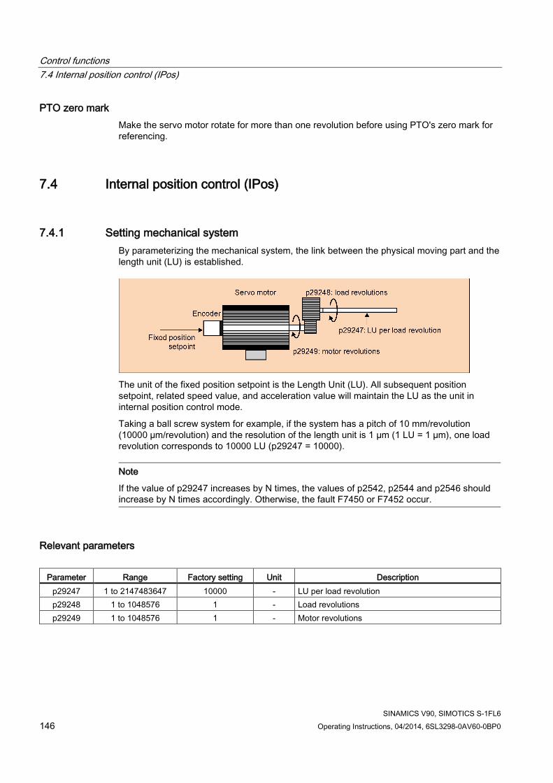
Control functions 7.4 Internal position control (IPos)
SINAMICS V90, SIMOTICS S-1FL6 146 Operating Instructions, 04/2014, 6SL3298-0AV60-0BP0
PTO zero mark Make the servo motor rotate for more than one revolution before using PTO's zero mark for referencing.
7.4 Internal position control (IPos)
7.4.1 Setting mechanical system By parameterizing the mechanical system, the link between the physical moving part and the length unit (LU) is established.
The unit of the fixed position setpoint is the Length Unit (LU). All subsequent position setpoint, related speed value, and acceleration value will maintain the LU as the unit in internal position control mode.
Taking a ball screw system for example, if the system has a pitch of 10 mm/revolution (10000 µm/revolution) and the resolution of the length unit is 1 µm (1 LU = 1 µm), one load revolution corresponds to 10000 LU (p29247 = 10000).
Note
If the value of p29247 increases by N times, the values of p2542, p2544 and p2546 should increase by N times accordingly. Otherwise, the fault F7450 or F7452 occur.
Relevant parameters
Parameter Range Factory setting Unit Description p29247 1 to 2147483647 10000 - LU per load revolution p29248 1 to 1048576 1 - Load revolutions p29249 1 to 1048576 1 - Motor revolutions
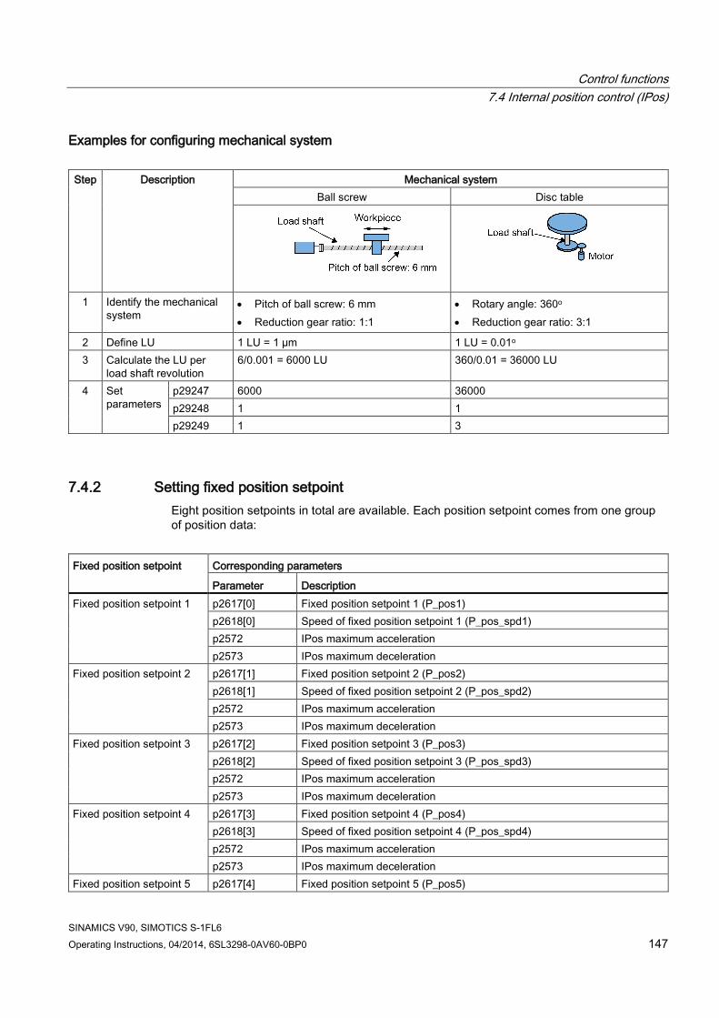
Control functions 7.4 Internal position control (IPos)
SINAMICS V90, SIMOTICS S-1FL6 Operating Instructions, 04/2014, 6SL3298-0AV60-0BP0 147
Examples for configuring mechanical system Step Description Mechanical system
Ball screw Disc table
1 Identify the mechanical system
• Pitch of ball screw: 6 mm • Reduction gear ratio: 1:1
• Rotary angle: 360o • Reduction gear ratio: 3:1
2 Define LU 1 LU = 1 µm 1 LU = 0.01o 3 Calculate the LU per
load shaft revolution 6/0.001 = 6000 LU 360/0.01 = 36000 LU
4 Set parameters
p29247 6000 36000 p29248 1 1 p29249 1 3
7.4.2 Setting fixed position setpoint Eight position setpoints in total are available. Each position setpoint comes from one group of position data:
Fixed position setpoint Corresponding parameters
Parameter Description Fixed position setpoint 1 p2617[0] Fixed position setpoint 1 (P_pos1)
p2618[0] Speed of fixed position setpoint 1 (P_pos_spd1) p2572 IPos maximum acceleration p2573 IPos maximum deceleration
Fixed position setpoint 2 p2617[1] Fixed position setpoint 2 (P_pos2) p2618[1] Speed of fixed position setpoint 2 (P_pos_spd2) p2572 IPos maximum acceleration p2573 IPos maximum deceleration
Fixed position setpoint 3 p2617[2] Fixed position setpoint 3 (P_pos3) p2618[2] Speed of fixed position setpoint 3 (P_pos_spd3) p2572 IPos maximum acceleration p2573 IPos maximum deceleration
Fixed position setpoint 4 p2617[3] Fixed position setpoint 4 (P_pos4) p2618[3] Speed of fixed position setpoint 4 (P_pos_spd4) p2572 IPos maximum acceleration p2573 IPos maximum deceleration
Fixed position setpoint 5 p2617[4] Fixed position setpoint 5 (P_pos5)

Control functions 7.4 Internal position control (IPos)
SINAMICS V90, SIMOTICS S-1FL6 148 Operating Instructions, 04/2014, 6SL3298-0AV60-0BP0
Fixed position setpoint Corresponding parameters
Parameter Description p2618[4] Speed of fixed position setpoint 5 (P_pos_spd5) p2572 IPos maximum acceleration p2573 IPos maximum deceleration
Fixed position setpoint 6 p2617[5] Fixed position setpoint 6 (P_pos6) p2618[5] Speed of fixed position setpoint 6 (P_pos_spd6) p2572 IPos maximum acceleration p2573 IPos maximum deceleration
Fixed position setpoint 7 p2617[6] Fixed position setpoint 7 (P_pos7) p2618[6] Speed of fixed position setpoint 7 (P_pos_spd7) p2572 IPos maximum acceleration p2573 IPos maximum deceleration
Fixed position setpoint 8 p2617[7] Fixed position setpoint 8 (P_pos8) p2618[7] Speed of fixed position setpoint 8 (P_pos_spd8) p2572 IPos maximum acceleration p2573 IPos maximum deceleration
Parameter settings
Parameter Range Factory setting Unit Description p2617[0]...[
7] -2147482648 to
2147482647 0 LU Fixed position setpoint 1 to 8
p2618[0]...[7]
1 to 40000000 600 1000 LU/min
Speed of fixed position setpoint 1 to 8
p2572 1 to 2000000 Motor dependent 1000 LU/s²
IPos maximum acceleration
p2573 1 to 2000000 Motor dependent 1000 LU/s²
IPos maximum deceleration
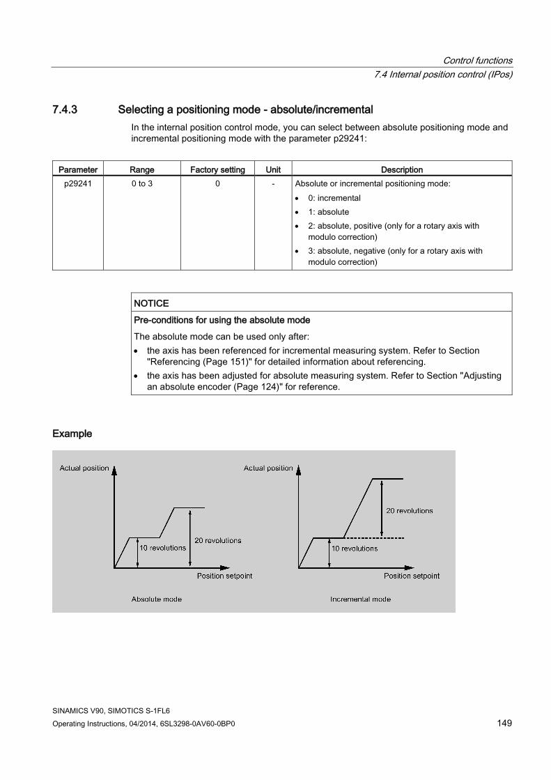
Control functions 7.4 Internal position control (IPos)
SINAMICS V90, SIMOTICS S-1FL6 Operating Instructions, 04/2014, 6SL3298-0AV60-0BP0 149
7.4.3 Selecting a positioning mode - absolute/incremental In the internal position control mode, you can select between absolute positioning mode and incremental positioning mode with the parameter p29241:
Parameter Range Factory setting Unit Description
p29241 0 to 3 0 - Absolute or incremental positioning mode: • 0: incremental • 1: absolute • 2: absolute, positive (only for a rotary axis with
modulo correction) • 3: absolute, negative (only for a rotary axis with
modulo correction)
NOTICE
Pre-conditions for using the absolute mode
The absolute mode can be used only after: • the axis has been referenced for incremental measuring system. Refer to Section
"Referencing (Page 151)" for detailed information about referencing. • the axis has been adjusted for absolute measuring system. Refer to Section "Adjusting
an absolute encoder (Page 124)" for reference.
Example

Control functions 7.4 Internal position control (IPos)
SINAMICS V90, SIMOTICS S-1FL6 150 Operating Instructions, 04/2014, 6SL3298-0AV60-0BP0
7.4.4 Configuring linear/modular axis Linear axis or modular axis can be used depending on your actual application. The linear axis has a restricted traversing range and it is the factory setting of the SINAMICS V90 servo drive.
The modular axis has an unrestricted traversing range. The value range of the position repeats itself after a value specified in p29245. You can use the modular axis by setting the following parameters additionally:
Parameter Range Unit Default Description
p29245 0 to 1 - 0 • 0: linear axis • 1: modular axis activation
p29246 1 to 2147482647 LU 360000 Modular range
Note
After modifying parameter p29245, you must perform the referencing again.
7.4.5 Backlash compensation Generally, backlash occurs when the mechanical force is transferred between a machine part and its drive:
If the mechanical system was to be adjusted/designed so that there was absolutely no backlash, this would result in high wear. Thus, backlash can occur between the machine component and the encoder. For axes with indirect position sensing, mechanical backlash results in a false traversing distance because the axis, at direction reversal, travels either too far or not far enough corresponding to the absolute value of the backlash.
Note Pre-conditions for backlash compensation
The backlash compensation is active after • the axis has been referenced for incremental measuring system. Refer to Section
"Referencing (Page 151)" for detailed information about referencing. • the axis has been adjusted for absolute measuring system. Refer to Section "Adjusting an
absolute encoder (Page 124)" for reference.

Control functions 7.4 Internal position control (IPos)
SINAMICS V90, SIMOTICS S-1FL6 Operating Instructions, 04/2014, 6SL3298-0AV60-0BP0 151
In order to compensate the backlash, the determined backlash must be specified in p2583 with correct polarity. At each direction of rotation reversal, the axis actual value is corrected dependent on the actual traversing direction.
If the axis has been referenced or adjusted, then the setting of parameter p2604 (reference point approach, starting direction) is used to activate the compensation value:
p2604 Traversing direction Activate compensation value
0 Negative Immediately 1 Positive Immediately
Parameter settings
Parameter Range Unit Default Description p2583 -200000 to
200000 LU 0 Backlash compensation
p2604 0 to 1 - 0 Set signal source for start direction of searching cam: • 0: start in positive direction • 1: start in negative direction
7.4.6 Referencing
Referencing modes If the servo motor has an absolute encoder, you can adjust the absolute encoder (by setting current position as the zero position) with the BOP function "ABS". Refer to Section "Adjusting an absolute encoder (Page 124)" for details.
If the servo motor has an incremental encoder, five referencing modes in total are available:
● Setting reference point with the digital input signal REF
● External reference cam (signal REF) and encoder zero mark
● Encoder zero mark only
● External reference cam (signal CWL) and encoder zero mark
● External reference cam (signal CCWL) and encoder zero mark
You can select one of these referencing modes by setting the parameter p29240:
Parameter Value Description
p29240 0 Setting reference point with the digital input signal REF 1 (default) External reference cam (signal REF) and encoder zero mark
2 Encoder zero mark only 3 External reference cam (signal CCWL) and encoder zero mark 4 External reference cam (signal CWL) and encoder zero mark

Control functions 7.4 Internal position control (IPos)
SINAMICS V90, SIMOTICS S-1FL6 152 Operating Instructions, 04/2014, 6SL3298-0AV60-0BP0
NOTICE
p29240 is inactive for absolute encoder
If an absolute encoder is connected, the parameter p29240 is inactive.
Setting reference point with the digital input signal REF (p29240=0)
NOTICE
Preconditions for this referencing mode • The servo motor must be stopped. • The signal REF must be OFF under the following conditions:
– before power-on – when switching from another referencing mode to this referencing mode – when switching from another control mode to internal position control mode
The current position is set to zero at a rising edge of the signal REF and the servo drive is referenced:
CAUTION
The referencing point may not be fixed during referencing.
The servo motor must be in servo on state so that the referencing point is fixed during referencing.
External reference cam (signal REF) and encoder zero mark (p29240=1) The referencing is triggered by signal SREF. After that, the servo motor accelerates to the speed specified in p2605 to find the reference cam. The direction (CW or CCW) for searching the reference cam is defined by p2604. When the reference cam is reached (signal REF: 0→1), the servo motor decelerates to standstill. After that, the servo motor accelerates again to the speed specified in p2608 and the running direction is opposite to the direction defined by p2604. Then the signal REF should be switched off (1→0). When the
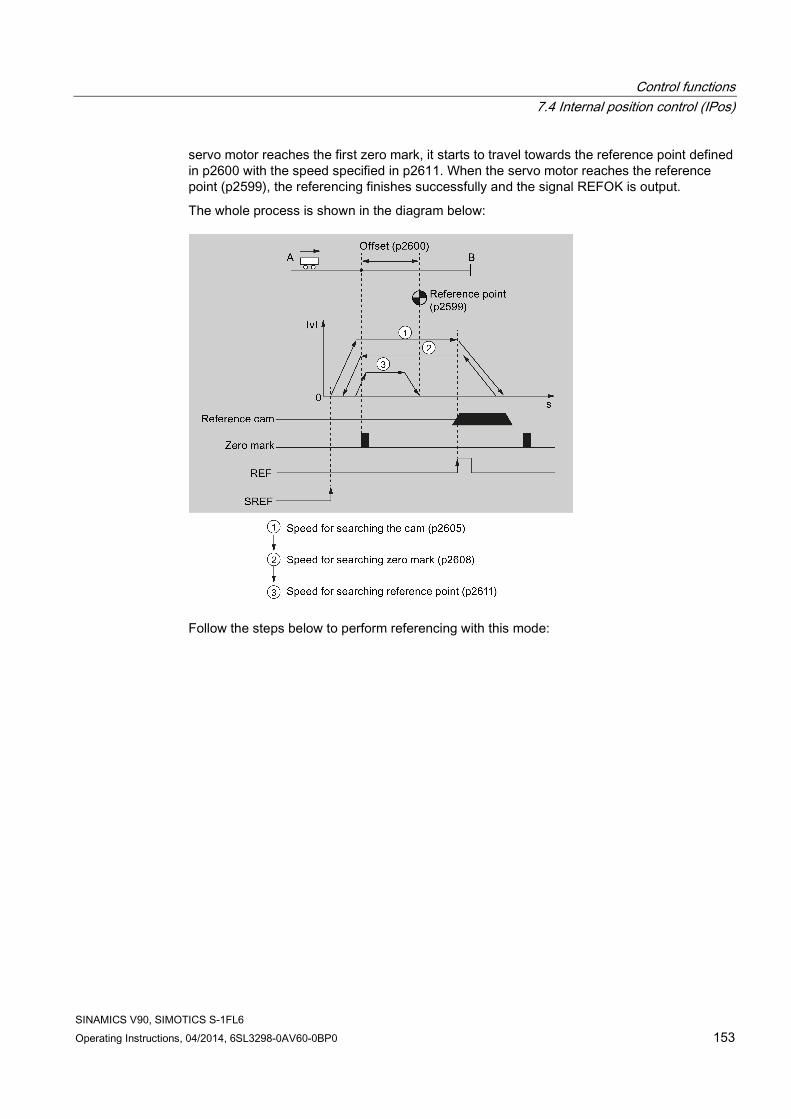
Control functions 7.4 Internal position control (IPos)
SINAMICS V90, SIMOTICS S-1FL6 Operating Instructions, 04/2014, 6SL3298-0AV60-0BP0 153
servo motor reaches the first zero mark, it starts to travel towards the reference point defined in p2600 with the speed specified in p2611. When the servo motor reaches the reference point (p2599), the referencing finishes successfully and the signal REFOK is output.
The whole process is shown in the diagram below:
Follow the steps below to perform referencing with this mode:
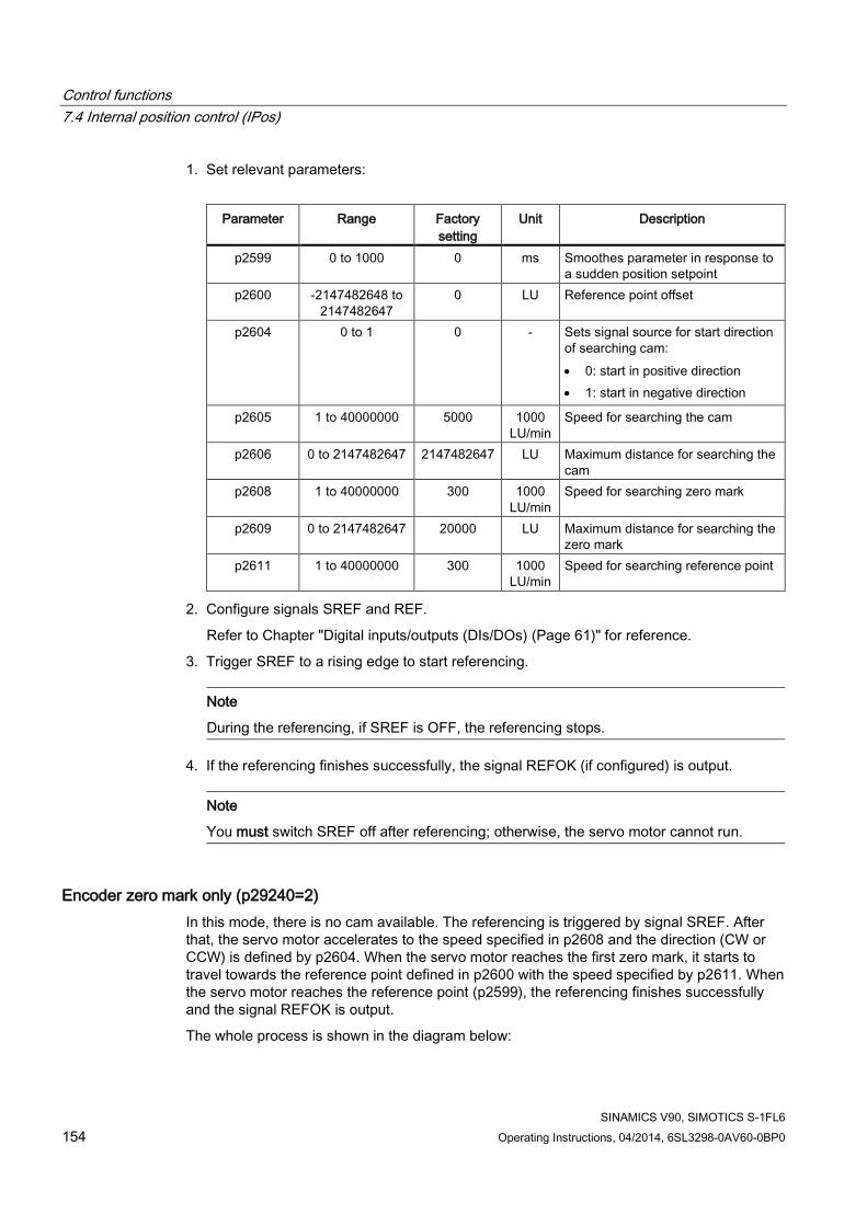
Control functions 7.4 Internal position control (IPos)
SINAMICS V90, SIMOTICS S-1FL6 154 Operating Instructions, 04/2014, 6SL3298-0AV60-0BP0
1. Set relevant parameters:
Parameter Range Factory setting
Unit Description
p2599 0 to 1000 0 ms Smoothes parameter in response to a sudden position setpoint
p2600 -2147482648 to 2147482647
0 LU Reference point offset
p2604 0 to 1 0 - Sets signal source for start direction of searching cam: • 0: start in positive direction • 1: start in negative direction
p2605 1 to 40000000 5000 1000 LU/min
Speed for searching the cam
p2606 0 to 2147482647 2147482647 LU Maximum distance for searching the cam
p2608 1 to 40000000 300 1000 LU/min
Speed for searching zero mark
p2609 0 to 2147482647 20000 LU Maximum distance for searching the zero mark
p2611 1 to 40000000 300 1000 LU/min
Speed for searching reference point
2. Configure signals SREF and REF.
Refer to Chapter "Digital inputs/outputs (DIs/DOs) (Page 61)" for reference.
3. Trigger SREF to a rising edge to start referencing.
Note
During the referencing, if SREF is OFF, the referencing stops.
4. If the referencing finishes successfully, the signal REFOK (if configured) is output.
Note
You must switch SREF off after referencing; otherwise, the servo motor cannot run.
Encoder zero mark only (p29240=2) In this mode, there is no cam available. The referencing is triggered by signal SREF. After that, the servo motor accelerates to the speed specified in p2608 and the direction (CW or CCW) is defined by p2604. When the servo motor reaches the first zero mark, it starts to travel towards the reference point defined in p2600 with the speed specified by p2611. When the servo motor reaches the reference point (p2599), the referencing finishes successfully and the signal REFOK is output.
The whole process is shown in the diagram below:

Control functions 7.4 Internal position control (IPos)
SINAMICS V90, SIMOTICS S-1FL6 Operating Instructions, 04/2014, 6SL3298-0AV60-0BP0 155
Follow the steps below to perform referencing with this mode:
1. Set relevant parameters:
Parameter Range Factory setting
Unit Description
p2599 0 to 1000 0 ms Smoothes parameter in response to a sudden position setpoint
p2600 -2147482648 to 2147482647
0 LU Reference point offset
p2604 0 to 1 0 - Sets signal source for start direction of searching cam: • 0: start in positive direction • 1: start in negative direction
p2608 1 to 40000000 300 1000 LU/min
Speed for searching zero mark
p2609 0 to 2147482647 20000 LU Maximum distance for searching the zero mark
p2611 1 to 40000000 300 1000 LU/min
Speed for searching reference point
2. Configure the signal SREF.

Control functions 7.4 Internal position control (IPos)
SINAMICS V90, SIMOTICS S-1FL6 156 Operating Instructions, 04/2014, 6SL3298-0AV60-0BP0
3. Trigger SREF to a rising edge to start referencing.
Note
During the referencing, if SREF is OFF, the referencing stops.
4. If the referencing finishes successfully, the signal REFOK (if configured) is output.
Note
You must switch SREF off after referencing; otherwise, the servo motor cannot run.
External reference cam (signal CCWL) and encoder zero mark (p29240=3) The referencing is triggered by signal SREF. After that, the servo motor accelerates to the speed specified in p2605 to find the reference cam. The direction (CCW) for searching the reference cam is defined by p2604. When the signal CCWL is detected, the servo motor decelerates to standstill with maximum deceleration. Then the servo motor accelerates again to the speed specified in p2608 and the running direction (CW) is opposite to the direction defined by p2604. When the servo motor finds the first zero mark, it starts to travel towards the reference point defined in p2600 with the speed specified in p2611. When the servo motor reaches the reference point (p2599), the referencing finishes successfully and the signal REFOK is output.
The whole process is shown in the diagram below:
Control functions 7.4 Internal position control (IPos)
SINAMICS V90, SIMOTICS S-1FL6 Operating Instructions, 04/2014, 6SL3298-0AV60-0BP0 157
Note • Once the referencing process is complete, the signal CCWL will act as limits signal again. • For the safety purpose, the maximum distance for searching the cam (p2606) and the
maximum distance for searching the zero mark (p2609) must be set.
Follow the steps below to perform referencing with this mode:
1. Set relevant parameters:
Parameter Range Factory setting
Unit Description
p2599 0 to 1000 0 ms Smoothes parameter in response to a sudden position setpoint.
p2600 -2147482648 to 2147482647
0 LU Reference point offset
p2604 1) 0 to 1 0 - Sets signal source for start direction of searching cam: • 0: start in positive direction (CW) • 1: start in negative direction
(CCW)
p2605 1 to 40000000 5000 1000 LU/min
Speed for searching the cam
p2606 0 to 2147482647 2147482647 LU Maximum distance for searching the cam
p2608 1 to 40000000 300 1000 LU/min
Speed for searching zero mark
p2609 0 to 2147482647 20000 LU Maximum distance for searching the zero mark
p2611 1 to 40000000 300 1000 LU/min
Speed for searching reference point
1) When p29240= 3, the direction for searching the reference cam must be CCW, that is p2604=1.
2. Configure the signal SREF and CCWL.
3. Trigger SREF to a rising edge to start referencing.
Note
During the referencing, if SREF is OFF, the referencing stops.
4. If the referencing finishes successfully, the signal REFOK (if configured) is output.
Note
You must switch SREF off after referencing; otherwise, the servo motor cannot run.

Control functions 7.4 Internal position control (IPos)
SINAMICS V90, SIMOTICS S-1FL6 158 Operating Instructions, 04/2014, 6SL3298-0AV60-0BP0
External reference cam (signal CWL) and encoder zero mark (p29240=4) The referencing is triggered by signal SREF. After that, the servo motor accelerates to the speed specified in p2605 to find the reference cam. The direction (CW) for searching the reference cam is defined by p2604. When the signal CWL is detected, the servo motor decelerates to standstill with maximum deceleration. Then the servo motor accelerates again to the speed specified in p2608 and the running direction (CCW) is opposite to the direction defined by p2604. When the servo motor finds the first zero mark, it starts to travel towards the reference point defined in p2600 with the speed specified in p2611. When the servo motor reaches the reference point (p2599), the referencing finishes successfully and the signal REFOK is output.
The whole process is shown in the diagram below:
Note • Once the referencing process is complete, the signal CWL will act as limits signal again. • For the safety purpose, the maximum distance for searching the cam (p2606) and the
maximum distance for searching the zero mark (p2609) must be set.

Control functions 7.4 Internal position control (IPos)
SINAMICS V90, SIMOTICS S-1FL6 Operating Instructions, 04/2014, 6SL3298-0AV60-0BP0 159
Follow the steps below to perform referencing with this mode:
1. Set relevant parameters:
Parameter Range Factory setting
Unit Description
p2599 0 to 1000 0 ms Smoothes parameter in response to a sudden position setpoint.
p2600 -2147482648 to 2147482647
0 LU Reference point offset
p2604 1) 0 to 1 0 - Sets signal source for start direction of searching cam: • 0: start in positive direction • 1: start in negative direction
p2605 1 to 40000000 5000 1000 LU/min
Speed for searching the cam
p2606 0 to 2147482647 2147482647 LU Maximum distance for searching the cam
p2608 1 to 40000000 300 1000 LU/min
Speed for searching zero mark
p2609 0 to 2147482647 20000 LU Maximum distance for searching the zero mark
p2611 1 to 40000000 300 1000 LU/min
Speed for searching reference point
1) When p29240= 4, the direction for searching the reference cam must be CW, that is p2604=0.
2. Configure the signal SREF and CWL.
3. Trigger SREF to a rising edge to start referencing.
Note
During the referencing, if SREF is OFF, the referencing stops.
4. If the referencing finishes successfully, the signal REFOK (if configured) is output.
Note
You must switch SREF off after referencing; otherwise, the servo motor cannot run.
7.4.7 Software position limit The following two software position limits are available in the internal position control mode:
● positive position limit
● negative position limit

Control functions 7.4 Internal position control (IPos)
SINAMICS V90, SIMOTICS S-1FL6 160 Operating Instructions, 04/2014, 6SL3298-0AV60-0BP0
The function of software position limit only becomes active after going to reference. When the actual position reaches one of the above-mentioned software position limits, motor speed decelerates to 0.
Parameter settings
Parameter Range Factory setting Unit Description p2580 -2147482648 to
2147482647 -2147482648 LU Negative software position limit switch
p2581 -2147482648 to 2147482647
2147482648 LU Positive software position limit switch
p2582 0 to 1 0 - Activation of software limit switch: • 0: deactivate • 1: activate
7.4.8 Speed limit Refer to "Speed limit (Page 140)" for details.
7.4.9 Torque limit Refer to "Torque limit (Page 141)" for details.
7.4.10 Selecting a fixed position setpoint and starting positioning In the IPos mode, two methods are available to select a fixed position setpoint and then start motor running according to selected fixed position setpoint:
● select a fixed position setpoint with the co-settings of signals POS1, POS2 and POS3 and then use the trigger signal P-TRG to start positioning
● use the rising edge of the signal STEPF, STEPB or STEPH
Refer to Chapter "Digital inputs/outputs (DIs/DOs) (Page 61)" for detailed information about the signals POS1, POS2, POS3, P-TRG, STEPF, STEPB, STEPH.

Control functions 7.4 Internal position control (IPos)
SINAMICS V90, SIMOTICS S-1FL6 Operating Instructions, 04/2014, 6SL3298-0AV60-0BP0 161
Selecting the target position with the signals POS1, POS2 and POS3, and starting the positioning with the trigger signal P-TRG
Select one of the eight fixed position setpoints with the co-settings of signals POS1, POS2 and POS3:
Fixed position setpoint Signal
POS3 POS2 POS1 Fixed position setpoint 1 0 0 0 Fixed position setpoint 2 0 0 1 Fixed position setpoint 3 0 1 0 Fixed position setpoint 4 0 1 1 Fixed position setpoint 5 1 0 0 Fixed position setpoint 6 1 0 1 Fixed position setpoint 7 1 1 0 Fixed position setpoint 8 1 1 1
In the fixed position control mode, the signals POS1 and POS2 are default assignments of DI7 and DI8 while the signal POS3 is not assigned:
Signal type Signal name Pin assignment Description
DI POS1 X8-11 Select a fixed position setpoint. DI POS2 X8-12 DI POS3 To be assigned
Note Configuration of POS3
If the POS3 is not assigned to any DI, its status is assumed to be 0, which means only the following fixed position setpoints can be used: • Fixed position setpoint 1 • Fixed position setpoint 2 • Fixed position setpoint 3 • Fixed position setpoint 4
After selecting a fixed position setpoint, the servo motor can start positioning at a rising edge of the signal P-TRG.
The digital input signal P-TRG is the default assignment of DI6 in the internal position control mode:
Signal type Signal name Pin assignment Setting Description
DI P-TRG X8-10 0→1 Starts positioning according to selected fixed position setpoint

Control functions 7.5 Speed control (S)
SINAMICS V90, SIMOTICS S-1FL6 162 Operating Instructions, 04/2014, 6SL3298-0AV60-0BP0
The timing diagram for starting positioning with the trigger signal P-TRG is shown as follows:
Selecting the target position and starting the positioning with the rising edge of the signal STEPF, STEPB or STEPH
If the signal STEPF is used, the servo motor, at a rising edge of STEPF, traverses to next fixed position setpoint. For example, if the servo motor currently locates at the fixed position setpoint 3, the servo motor traverses to the fixed position setpoint 4 at a rising edge of STEPF.
If the signal STEPB is used, the servo motor, at a rising edge of STEPB, traverses to previous fixed position setpoint.
If the signal STEPH is used, the servo motor, at a rising edge of STEPH, traverses to the fixed position setpoint 1.
Note
The servo drive can respond to the rising edge of the signal STEPF, STEPB or STEPH only when the servo motor is at a standstill.
If the servo motor is at fixed position 8, a rising edge of STEPF is not responded.
If motor is at fixed position 1, a rising edge of STEPH is responded, but a rising edge of STEPB is not responded.
7.5 Speed control (S)
7.5.1 Configuring speed setpoint Eight sources in total are available for speed setpoint. You can select one of them with the combination of digital input signals SPD1, SPD2 and SPD3:
Digital signal Torque limit
SPD3 SPD2 SPD1 0 0 0 External analog speed setpoint (analog input 1) 0 0 1 Fixed speed setpoint 1 (p1001)

Control functions 7.5 Speed control (S)
SINAMICS V90, SIMOTICS S-1FL6 Operating Instructions, 04/2014, 6SL3298-0AV60-0BP0 163
Digital signal Torque limit
SPD3 SPD2 SPD1 0 1 0 Fixed speed setpoint 2 (p1002) 0 1 1 Fixed speed setpoint 3 (p1003) 1 0 0 Fixed speed setpoint 4 (p1004) 1 0 1 Fixed speed setpoint 5 (p1005) 1 1 0 Fixed speed setpoint 6 (p1006) 1 1 1 Fixed speed setpoint 7 (p1007)
Refer to "DIs (Page 62)" for more information about the digital signals SPD1, SPD2 and SPD3.
7.5.1.1 Speed control with external analog speed setpoint In the S mode, when the digital input signals SPD1, SPD2 and SPD3 are all at low level (0), analog voltage from the analog input 1 is used as the speed setpoint.
The analog voltage from the analog input 1 correponds to a parameterized speed value. Default speed value is rated motor speed. The analog voltage of 10 V corresponds to the maximum speed setpoint (V_max) and this maximum speed setpoint can be specified by parameter p29060.
Parameter Range Factory setting Unit Description
p29060 6 to 210000 3000 rpm Maximum analog speed setpoint corresponding to 10 V
The relationship between the analog voltage and the speed setpoint is shown as follows:

Control functions 7.5 Speed control (S)
SINAMICS V90, SIMOTICS S-1FL6 164 Operating Instructions, 04/2014, 6SL3298-0AV60-0BP0
Offset adjustment for analog input 1 Offset exists for the input voltage from the analog input 1. You have two methods to adjust such offset:
● Automatic adjustment with BOP function: refer to "Adjusting AI offsets (Page 122)" for details.
● Manual input of an offset value (p29061)
Parameter Range Factory setting Unit Description p29061 -0.50 to 0.50 0 V Offset adjustment for analog
input 1 (speed setpoint)
7.5.1.2 Speed control with fixed speed setpoint
Parameter settings In the S mode, when at least one of the three digital input signals SPD1, SPD2 and SPD3 is at high level, one of the following parameter values is used as speed setpoint:
Parameter Value range Default Unit Description Digital input
SPD3 SPD2 SPD2 p1001 -210000 to
210000 0 rpm Fixed speed setpoint 1 0 0 1
p1002 -210000 to 210000
0 rpm Fixed speed setpoint 2 0 1 0
p1003 -210000 to 210000
0 rpm Fixed speed setpoint 3 0 1 1
p1004 -210000 to 210000
0 rpm Fixed speed setpoint 4 1 0 0

Control functions 7.5 Speed control (S)
SINAMICS V90, SIMOTICS S-1FL6 Operating Instructions, 04/2014, 6SL3298-0AV60-0BP0 165
Parameter Value range Default Unit Description Digital input
SPD3 SPD2 SPD2 p1005 -210000 to
210000 0 rpm Fixed speed setpoint 5 1 0 1
p1006 -210000 to 210000
0 rpm Fixed speed setpoint 6 1 1 0
p1007 -210000 to 210000
0 rpm Fixed speed setpoint 7 1 1 1
7.5.2 Direction and stop Two digital input signals are used to control motor direction and run/stop.
● CWE: clockwise enable
● CCWE: counter-clockwise enable
The following table shows you in details:
Signal Fixed speed setpoint Analog speed setpoint
CCWE CWE + polarity - polarity 0 V 0 0 Stop Stop Stop Stop 0 1 CW CW CCW Stop 1 0 CCW CCW CW Stop 1 1 Stop Stop Stop Stop
Note
For more information about signals CWE and CCWE, refer to "DIs (Page 62)".
7.5.3 Speed limit Refer to "Speed limit (Page 140)" for details.
7.5.4 Torque limit Refer to "Torque limit (Page 141)" for details.

Control functions 7.5 Speed control (S)
SINAMICS V90, SIMOTICS S-1FL6 166 Operating Instructions, 04/2014, 6SL3298-0AV60-0BP0
7.5.5 Zero speed clamp The function of zero speed clamp is used to stop motor and lock motor axis when motor speed setpoint is below a parameterized threshold level (p29075).
This function is available only when the analog input 1 is used as the source of speed setpoint. The digital input signal ZSCLAMP is used to activate this function. When both motor speed setpoint and motor actual speed are below the parameterized threshold level and signal ZSCLAMP is logic "1", the motor is locked. Drive exits from clamping state either when the motor speed setpoint is above the threshold level or when the signal ZSCLAMP is logic "0".
Parameter settings
Parameter Value range Default Unit Description p29075 0 to 200 200 rpm Zero speed clamp threshold p29060 6 to 210000 3000 % Maximum analog speed setpoint corresponding to 10 V
DI configuration
Signal type Signal name Pin assignment Setting Description DI ZSCLAMP To be assigned 1 When the motor speed setpoint is below zero speed
clamp threshold, the motor is locked. 0 No action
Note
When p29003=4 and CMODE is "1", the drive is working in speed control mode. In this case if ZSCLAMP is activated, the drive will switch to PTI control mode and PTI pulse input will lead motor running under PTI control mode.
Note
For more information about the signal ZSCLAMP, refer to "DIs (Page 62)".
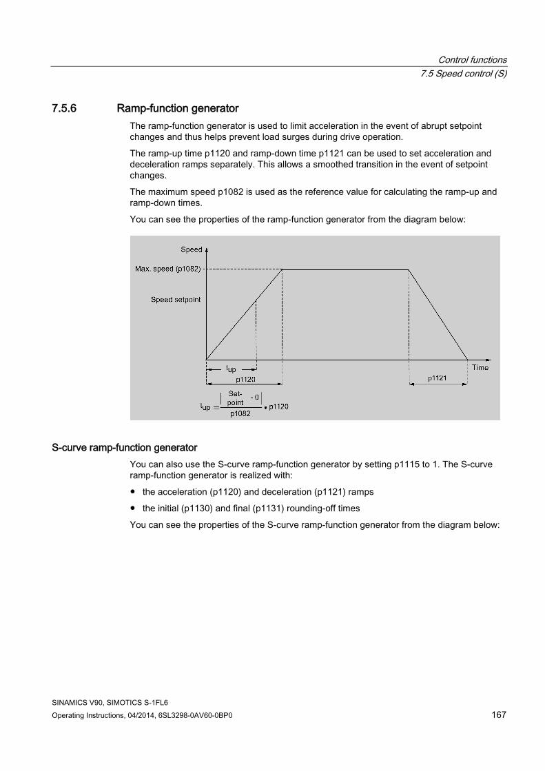
Control functions 7.5 Speed control (S)
SINAMICS V90, SIMOTICS S-1FL6 Operating Instructions, 04/2014, 6SL3298-0AV60-0BP0 167
7.5.6 Ramp-function generator The ramp-function generator is used to limit acceleration in the event of abrupt setpoint changes and thus helps prevent load surges during drive operation.
The ramp-up time p1120 and ramp-down time p1121 can be used to set acceleration and deceleration ramps separately. This allows a smoothed transition in the event of setpoint changes.
The maximum speed p1082 is used as the reference value for calculating the ramp-up and ramp-down times.
You can see the properties of the ramp-function generator from the diagram below:
S-curve ramp-function generator You can also use the S-curve ramp-function generator by setting p1115 to 1. The S-curve ramp-function generator is realized with:
● the acceleration (p1120) and deceleration (p1121) ramps
● the initial (p1130) and final (p1131) rounding-off times
You can see the properties of the S-curve ramp-function generator from the diagram below:

Control functions 7.6 Torque control (T)
SINAMICS V90, SIMOTICS S-1FL6 168 Operating Instructions, 04/2014, 6SL3298-0AV60-0BP0
Parameter settings
Parameter Value range Default Unit Description p1082 0 to 210000 1500 rpm Maximum motor speed p1115 0 to 1 0 - Ramp-function generator selection p1120 0 to 999999 1 s Ramp-function generator ramp-up time p1121 0 to 999999 1 s Ramp-function generator ramp-down time p1130 0 to 30 0 s Ramp-function generator initial rounding-off time p1131 0 to 30 0 s Ramp-function generator final rounding-off time
7.6 Torque control (T)
7.6.1 300% overload capacity SINAMICS V90 servo drives can work with 300% overload capacity for a specific time period. The following diagrams show in details:

Control functions 7.6 Torque control (T)
SINAMICS V90, SIMOTICS S-1FL6 Operating Instructions, 04/2014, 6SL3298-0AV60-0BP0 169
● Without load
● With load
7.6.2 Torque setpoint Two sources are available for torque setpoint:
● External setpoint: analog input 2
● Fixed setpoint: p29043
These two resources can be selected with the digital input signal TSET:

Control functions 7.6 Torque control (T)
SINAMICS V90, SIMOTICS S-1FL6 170 Operating Instructions, 04/2014, 6SL3298-0AV60-0BP0
Signal Level Source of torque setpoint TSET 0 (default) Analog torque setpoint (analog input 2)
1 Fixed torque setpoint (p29043)
Refer to "DIs (Page 62)" for detailed information about the signal TSET.
7.6.2.1 Torque control with external analog torque setpoint In the T mode, when the digital input signal TSET is at low level, analog voltage from the analog input 2 is used as the torque setpoint.
The analog voltage from the analog input 2 corresponds to a parameterized torque value scaling (p29041[0]). If p29041[0] = 100%, analog input voltage of 10 V corresponds to rated torque; if p29041[0] = 50%, the analog input value of 10 V corresponds to 50% of the rated torque.
Parameter Range Factory setting Unit Description p29041[0] 0 to 100 100 % Scaling for analog torque setpoint (corresponding to 10
V)
Note
The value of analog input 2 can be monitored through parameter r0755.
Offset adjustment for analog input 2 Offset exists for the input voltage from the analog input 2. The motor can run at a very low speed even the current input voltage is 0 V. You have 2 methods to adjust such offset:
● Automatic adjustment with BOP function: refer to "Adjusting AI offsets (Page 122)" for details.
● Manual input of an offset value (p29042)
Parameter Range Factory setting Unit Description p29042 -0.50 to 0.50 0 V Offset adjustment for analog input 2
(torque setpoint)
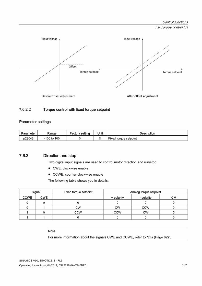
Control functions 7.6 Torque control (T)
SINAMICS V90, SIMOTICS S-1FL6 Operating Instructions, 04/2014, 6SL3298-0AV60-0BP0 171
7.6.2.2 Torque control with fixed torque setpoint
Parameter settings
Parameter Range Factory setting Unit Description p29043 -100 to 100 0 % Fixed torque setpoint
7.6.3 Direction and stop Two digital input signals are used to control motor direction and run/stop:
● CWE: clockwise enable
● CCWE: counter-clockwise enable
The following table shows you in details:
Signal Fixed torque setpoint Analog torque setpoint
CCWE CWE + polarity - polarity 0 V 0 0 0 0 0 0 0 1 CW CW CCW 0 1 0 CCW CCW CW 0 1 1 0 0 0 0
Note
For more information about the signals CWE and CCWE, refer to "DIs (Page 62)".

Control functions 7.7 Absolute position system
SINAMICS V90, SIMOTICS S-1FL6 172 Operating Instructions, 04/2014, 6SL3298-0AV60-0BP0
7.6.4 Speed limit Refer to "Speed limit (Page 140)" for details.
7.7 Absolute position system When the SINAMICS V90 servo drive uses a servo motor with an absolute encoder. the current absolute position can be detected and transmitted to the controller. With this function of absolute position system, you can perform motion control task immediately after the servo system is powered on, which means you do not have to carry out referencing or zero position operation beforehand.
Restrictions The absolute position system cannot be configured under the following conditions:
● Internal position control (IPos)
● Speed control (S)
● Torque control (T)
● Control change mode
● Strokeless coordinate system, for example, rotary shaft, infinitely long positioning operation
● Change of electronic gear after referencing
● Use of alarm code output
7.7.1 USS communication telegram As mentioned before, the SINAMICS V90 servo drive communicates with the PLC through an RS485 cable and the standard USS communication protocol is used.

Control functions 7.7 Absolute position system
SINAMICS V90, SIMOTICS S-1FL6 Operating Instructions, 04/2014, 6SL3298-0AV60-0BP0 173
Telegram format The telegram format is shown as follows:
STX LGE ADR PKE IND PWE PWE BCC
STX: start of text LGE: length ADR: slave address PKE: parameter ID IND: sub-index PWE: parameter value BCC: block check character
7.7.2 Transmitting sequence for the absolute position data The following table shows you the transmitting sequence for the absolute position data:
Main step Sub step/comment
① Set PTI control mode. Set p29003 = 0.
② Enable absolute position mode. Set p29250 = 1.

Control functions 7.7 Absolute position system
SINAMICS V90, SIMOTICS S-1FL6 174 Operating Instructions, 04/2014, 6SL3298-0AV60-0BP0
Main step Sub step/comment
③ Configure relative parameters. 1. Set PTI input parameters (p29010 to p29014). 2. Set position control parameters (p29247 to p29249). 3. Set electrical gear p29012 and p29013.
④ Referencing with the BOP or SINAMICS V-ASSISTANT.
1. Run the servo motor for a proper distance. 2. Adjust the absolute encoder with the BOP menu function "ABS"
or SINAMICS V-ASSISTANT. NOTE: You must perform the referencing operation under the following conditions: • System setup is performed. • The servo drive has been changed. • The servo motor has been changed. • An alarm occurs.
⑤ Configure the parameters for the USS communication.
1. Set RS485 address (p29004). 2. Set baud rate (38400 bps).
⑥ Start transmitting.
⑦ Transmit the calibration status of the absolute encoder to the PLC.
1. Turn on the servo-on enable signal (SON). 2. The PLC checks the standstill status and alarm status through
the digital output of the servo drive. 3. If there is no alarm and the motor is in standstill status, the PLC
sends a data request to the servo drive through the RS485 cable. 4. In response to the data request from PLC, the servo drive
transmits calibration status (p2507[0]=3) of encoder to the PLC.
⑧ Transmit the absolute position data to the PLC. 1. If the absolute encoder is calibrated, and meanwhile, the servo drive is ready (the digital output RDY is logic 1) and in standstill status (the digital output signal INP is logic 1), the PLC sends a data request to drive through the RS485 cable.
2. In response to the data request from the PLC, the servo drive transmits the absolute position data (r2521) to the PLC.

SINAMICS V90, SIMOTICS S-1FL6 Operating Instructions, 04/2014, 6SL3298-0AV60-0BP0 175
Safety Integrated function 8 8.1 Standards and regulations
8.1.1 General information
8.1.1.1 Aims Manufacturers and operating companies of equipment, machines, and products are responsible for ensuring the required level of safety. This means that plants, machines, and other equipment must be designed to be as safe as possible in accordance with the current state of the art. To ensure this, companies describe in the various standards the current state of the art covering all aspects relevant to safety. When the relevant Standards are observed, this ensures that state-of-the-art technology has been utilized and, in turn, the erector/builder of a plant or a manufacturer of a machine or a piece of equipment has fulfilled his appropriate responsibility.
Safety systems are designed to minimize potential hazards for both people and the environment by means of suitable technical equipment, without restricting industrial production and the use of machines more than is necessary. The protection of man and environment must be assigned equal importance in all countries, which is it is important that rules and regulations that have been internationally harmonized are applied. This is also designed to avoid distortions in the competition due to different safety requirements in different countries.
There are different concepts and requirements in the various regions and countries of the world when it comes to ensuring the appropriate degree of safety. The legislation and the requirements of how and when proof is to be given and whether there is an adequate level of safety are just as different as the assignment of responsibilities. The most important thing for manufacturers of machines and companies that set up plants and systems is that the legislation and regulations in the country where the machine or plant is being operated apply. For example, the control system for a machine that is to be used in the US must fulfill local US requirements even if the machine manufacturer (OEM) is based in the European Economic Area (EEA).
8.1.1.2 Functional safety Safety, from the perspective of the object to be protected, cannot be split-up. The causes of hazards and, in turn, the technical measures to avoid them can vary significantly. This is why a differentiation is made between different types of safety (e.g. by specifying the cause of possible hazards). "Functional safety" is involved if safety depends on the correct function. To ensure the functional safety of a machine or plant, the safety-related parts of the protection and control devices must function correctly. In addition, the systems must behave in such a way that either the plant remains in a safe state or it is brought into a safe state if a fault occurs. In this case, it is necessary to use specially qualified technology that fulfills the

Safety Integrated function 8.1 Standards and regulations
SINAMICS V90, SIMOTICS S-1FL6 176 Operating Instructions, 04/2014, 6SL3298-0AV60-0BP0
requirements described in the associated Standards. The requirements to achieve functional safety are based on the following basic goals:
● Avoiding systematic faults
● Controlling systematic faults
● Controlling random faults or failures
Benchmarks for establishing whether or not a sufficient level of functional safety has been achieved include the probability of hazardous failures, the fault tolerance, and the quality that is to be ensured by minimizing systematic faults. This is expressed in the Standards using different terms. In IEC/EN 61508, IEC/EN 62061 "Safety Integrity Level" (SIL) and EN ISO 13849-1 "Categories" and "Performance Level" (PL).
8.1.2 Safety of machinery in Europe The EU Directives that apply to the implementation of products are based on Article 95 of the EU contract, which regulates the free exchange of goods. These are based on a new global concept ("new approach", "global approach"):
● EU Directives only specify general safety goals and define basic safety requirements.
● Technical details can be defined by means of standards by Standards Associations that have the appropriate mandate from the commission of the European Parliament and Council (CEN, CENELEC). These standards are harmonized in line with a specific directive and listed in the official journal of the commission of the European Parliament and Council. Legislation does not specify that certain standards have to be observed. When the harmonized Standards are observed, it can be assumed that the safety requirements and specifications of the Directives involved have been fulfilled.
● EU Directives specify that the Member States must mutually recognize domestic regulations.
The EU Directives are equal. This means that if several Directives apply for a specific piece of equipment or device, the requirements of all of the relevant Directives apply (e.g. for a machine with electrical equipment, the Machinery Directive and the Low-Voltage Directive apply).
8.1.2.1 Machinery Directive The basic safety and health requirements specified in Annex I of the Directive must be fulfilled for the safety of machines.
The protective goals must be implemented responsibly to ensure compliance with the Directive.
Manufacturers of a machine must verify that their machine complies with the basic requirements. This verification is facilitated by means of harmonized standards.
8.1.2.2 Harmonized European Standards The two Standards Organizations CEN (Comité Européen de Normalisation) and CENELEC (Comité Européen de Normalisation Électrotechnique), mandated by the EU Commission,
Safety Integrated function 8.1 Standards and regulations
SINAMICS V90, SIMOTICS S-1FL6 Operating Instructions, 04/2014, 6SL3298-0AV60-0BP0 177
drew-up harmonized European standards in order to precisely specify the requirements of the EC directives for a specific product. These standards (EN standards) are published in the official journal of the commission of the European Parliament and Council and must be included without revision in domestic standards. They are designed to fulfill basic health and safety requirements as well as the protective goals specified in Annex I of the Machinery Directive.
When the harmonized standards are observed, it is "automatically assumed" that the Directive is fulfilled. As such, manufacturers can assume that they have observed the safety aspects of the Directive under the assumption that these are also covered in this standard. However, not every European Standard is harmonized in this sense. Key here is the listing in the official journal of the commission of the European Parliament and Council.
The European Safety of Machines standard is hierarchically structured. It is divided into:
● A standards (basic standards)
● B standards (group standards)
● C standards (product standards)
Type A standards/basic standards
A standards include basic terminology and definitions relating to all types of machine. This includes EN ISO 12100-1 (previously EN 292-1) "Safety of Machines, Basic Terminology, General Design Principles".
A standards are aimed primarily at the bodies responsible for setting the B and C standards. The measures specified here for minimizing risk, however, may also be useful for manufacturers if no applicable C standards have been defined.
Type B standards/group standards
B standards cover all safety-related standards for various different machine types. B standards are aimed primarily at the bodies responsible for setting C standards. They can also be useful for manufacturers during the machine design and construction phases, however, if no applicable C standards have been defined.
A further sub-division has been made for B standards:
● Type B1 standards for higher-level safety aspects (e.g. ergonomic principles, safety clearances from sources of danger, minimum clearances to prevent parts of the body from being crushed).
● Type B2 standards for protective safety devices are defined for different machine types (e.g. EMERGENCY STOP devices, two-hand operating circuits, interlocking elements, contactless protective devices, safety-related parts of controls).
Type C standards/product standards
C standards are product-specific standards (e.g. for machine tools, woodworking machines, elevators, packaging machines, printing machines etc.). Product standards cover machine-specific requirements. The requirements can, under certain circumstances, deviate from the basic and group standards. Type C/product standards have the highest priority for machine manufacturers who can assume that it fulfills the basic requirements of Annex I of the Machinery Directive (automatic presumption of compliance). If no product standard has been defined for a particular machine, type B standards can be applied when the machine is constructed.

Safety Integrated function 8.1 Standards and regulations
SINAMICS V90, SIMOTICS S-1FL6 178 Operating Instructions, 04/2014, 6SL3298-0AV60-0BP0
A complete list of the standards specified and the mandated draft standards are available on the Internet at the following address:
http://www.newapproach.org/
Recommendation: Due to the rapid pace of technical development and the associated changes in machine concepts, the standards (and C standards in particular) should be checked to ensure that they are up to date. Please note that the application of a particular standard may not be mandatory provided that all the safety requirements of the applicable EU directives are fulfilled.
8.1.2.3 Standards for implementing safety-related controllers If the functional safety of a machine depends on various control functions, the controller must be implemented in such a way that the probability of the safety functions failing is sufficiently minimized. EN ISO 13849-1 (formerly EN 954-1) and EN IEC61508 define principles for implementing safety-related machine controllers which, when properly applied, ensure that all the safety requirements of the EC Machinery Directive are fulfilled. These standards ensure that the relevant safety requirements of the Machinery Directive are fulfilled.
Figure 8-1 Standards for implementing safety-related controllers
The application areas of EN ISO 13849-1, EN 62061, and EN 61508 are very similar. To help users make an appropriate decision, the IEC and ISO associations have specified the application areas of both standards in a joint table in the introduction to the standards. EN ISO 13849-1 or EN 62061 should be applied depending on the technology (mechanics, hydraulics, pneumatics, electrics, electronics and programmable electronics), risk classification and architecture.

Safety Integrated function 8.1 Standards and regulations
SINAMICS V90, SIMOTICS S-1FL6 Operating Instructions, 04/2014, 6SL3298-0AV60-0BP0 179
Type Systems for executing safety-related control
functions EN ISO 13849-1 EN 62061
A Non-electrical (e.g. hydraulic, pneumatic) X Not covered B Electromechanical (e.g. relay and/or basic
electronics) Restricted to the designated architectures (see comment 1) and max. up to PL = e
All architectures and max. up to SIL 3
C Complex electronics (e.g. programmable electronics)
Restricted to the designated architectures (see comment 1) and max. up to PL = d
All architectures and max. up to SIL 3
D A standards combined with B standards Restricted to the designated architectures (see comment 1) and max. up to PL = e
X See comment 3
E C standards combined with B standards Restricted to the designated architectures (see comment 1) and max. up to PL = d
All architectures and max. up to SIL 3
F C standards combined with A standards or C standards combined with A standards and B standards
X See comment 2
X See comment 3
"X" indicates that the point is covered by this standard. Comment 1: Designated architectures are described in Annex B of EN ISO 13849-1 and provide a simplified basis for the quantification. Comment 2: For complex electronics: Using designated architectures in compliance with EN ISO 13849-1 up to PL = d or every architecture in compliance with EN 62061. Comment 3: For non-electrical systems: Use components that comply with EN ISO 13849-1 as sub-systems.
8.1.2.4 DIN EN ISO 13849-1 (replaces EN 954-1) A qualitative analysis according to DIN EN 13849-1 is not sufficient for modern control systems due to their technology. Among other things, DIN EN ISO 13849-1 does not take into account time behavior (e.g. test interval and/or cyclic test, lifetime). This results in the probabilistic approach in DIN EN ISO 13849-1 (probability of failure per unit time). DIN EN ISO 13849-1 is based on the known categories of EN 954-1. It now also takes into account complete safety functions and all the devices required to execute these. With DIN EN ISO 13849-1, safety functions are investigated from a quantitative perspective going beyond the qualitative basis of EN 954-1. Performance levels (PL), which are based on the categories, are used. The following safety-related characteristic quantities are required for devices/equipment:
● Category (structural requirement)
● PL: Performance level
● MTTFd: Mean time to dangerous failure
● DC: Diagnostic coverage
● CCF: Common cause failure

Safety Integrated function 8.1 Standards and regulations
SINAMICS V90, SIMOTICS S-1FL6 180 Operating Instructions, 04/2014, 6SL3298-0AV60-0BP0
The standard describes how the performance level (PL) is calculated for safety-related components of the controller on the basis of designated architectures. In the event of any deviations from this, EN ISO 13849-1 refers to EN 61508.
When combining several safety-related parts to form a complete system, the standard explains how to determine the resulting PL.
Note DIN EN ISO 13849-1 and machinery directive
Since May 2007, DIN EN ISO 13849-1 has been harmonized as part of the Machinery Directive.
8.1.2.5 EN 62061 EN 62061 (identical to IEC 62061) is a sector-specific standard subordinate to IEC/EN 61508. It describes the implementation of safety-related electrical machine control systems and looks at the complete life cycle, from the conceptual phase to decommissioning. The standard is based on the quantitative and qualitative analyses of safety functions, whereby it systematically applies a top-down approach to implementing complex control systems (known as "functional decomposition"). The safety functions derived from the risk analysis are sub-divided into sub-safety functions, which are then assigned to real devices, sub-systems, and sub-system elements. Both the hardware and software are covered. EN 62061 also describes the requirements placed on implementing application programs.
A safety-related control system comprises different sub-systems. From a safety perspective, the sub-systems are described in terms of the SIL claim limit and PFHD characteristic quantities. Programmable electronic devices (e.g. PLCs or variable-speed drives) must fulfill EN 61508. They can then be integrated in the controller as sub-systems. The following safety-related characteristic quantities must be specified by the manufacturers of these devices.
Safety-related characteristic quantities for subsystems:
● SIL CL: SIL claim limit
● PFHD: Probability of dangerous failures per hour
● T1: Lifetime
Simple sub-systems (e.g. sensors and actuators) in electromechanical components can, in turn, comprise sub-system elements (devices) interconnected in different ways with the characteristic quantities required for determining the relevant PFHD value of the sub-system.
Safety-related characteristic quantities for subsystem elements (devices):
● λ: Failure rate
● B10 value: For elements that are subject to wear
● T1: Lifetime
For electromechanical devices, a manufacturer specifies a failure rate λ with reference to the number of operating cycles. The failure rate per unit time and the lifetime must be determined using the switching frequency for the particular application.

Safety Integrated function 8.1 Standards and regulations
SINAMICS V90, SIMOTICS S-1FL6 Operating Instructions, 04/2014, 6SL3298-0AV60-0BP0 181
Parameters for the sub-system, which comprises sub-system elements, that must be defined during the design phase:
● T2: Diagnostic test interval
● β: Susceptibility to common cause failure
● DC: Diagnostic coverage
The PFHD value of the safety-related controller is determined by adding the individual PFHD values for subsystems. The user has the following options when setting up a safety-related controller:
● Use devices and sub-systems that already comply with EN ISO 13849-1, IEC/EN 61508, or IEC/EN 62061. The standard provides information specifying how qualified devices can be integrated when safety functions are implemented.
● Develop own subsystems:
– Programmable, electronic systems and complex systems: Application of EN 61508 or EN 61800-5-2.
– Simple devices and subsystems: Application of EN 62061.
EN 62061 does not include information about non-electric systems. The standard provides detailed information on implementing safety-related electrical, electronic, and programmable electronic control systems. EN ISO 13849-1 must be applied for non-electric systems.
Note Function examples
Details of simple sub-systems that have been implemented and integrated are now available as "functional examples".
Note EN 62061 and machinery directive
IEC 62061 has been ratified as EN 62061 in Europe and harmonized as part of the Machinery Directive.
8.1.2.6 Series of standards EN 61508 (VDE 0803) This series of standards describes the current state of the art.
EN 61508 is not harmonized in line with any EU directives, which means that an automatic presumption of conformity for fulfilling the protective requirements of a directive is not implied. The manufacturer of a safety-related product, however, can also use EN 61508 to fulfill basic requirements of European directives in accordance with the latest conceptual design, for example, in the following cases:
● If no harmonized standard exists for the application in question. In this case, the manufacturer can use EN 61508, although no presumption of conformity exists here.
● A harmonized European standard (e.g. EN 62061, EN ISO 13849, EN 60204-1) references EN 61508. This ensures that the appropriate requirements of the directives are fulfilled ("standard that is also applicable"). When manufacturers apply EN 61508
Safety Integrated function 8.1 Standards and regulations
SINAMICS V90, SIMOTICS S-1FL6 182 Operating Instructions, 04/2014, 6SL3298-0AV60-0BP0
properly and responsibly in accordance with this reference, they can use the presumption of conformity of the referencing standard.
EN 61508 covers all the aspects that must be taken into account when E/E/PES systems (electrical, electronic, and programmable electronic System) are used in order to execute safety functions and/or to ensure the appropriate level of functional safety. Other hazards (e.g. electric shock) are, as in EN ISO 13849, not part of the standard.
EN 61508 has recently been declared the "International Basic Safety Publication", which makes it a framework for other, sector-specific standards (e.g. EN 62061). As a result, this standard is now accepted worldwide, particularly in North America and in the automotive industry. Today, many regulatory bodies already stipulate it (e.g. as a basis for NRTL listing).
Another recent development with respect to EN 61508 is its system approach, which extends the technical requirements to include the entire safety installation from the sensor to the actuator, the quantification of the probability of hazardous failure due to random hardware failures, and the creation of documentation covering all phases of the safety-related lifecycle of the E/E/PES.
8.1.2.7 Risk analysis/assessment Risks are intrinsic in machines due to their design and functionality. For this reason, the Machinery Directive requires that a risk assessment be performed for each machine and, if necessary, the level of risk reduced until the residual risk is less than the tolerable risk. To assess these risks, the following standards must be applied:
EN ISO 12100-1 "Safety of Machinery - basic terminology, general principles for design"
EN ISO 13849-1 (successor to EN 954-1) "Safety-related parts of control systems"
EN ISO 12100-1 focuses on the risks to be analyzed and the design principles for minimizing risk.
The risk assessment is a procedure that allows hazards resulting from machines to be systematically investigated. Where necessary, the risk assessment is followed by a risk reduction procedure. When the procedure is repeated, this is known as an iterative process. This can help eliminate hazards (as far as this is possible) and can act as a basis for implementing suitable protective measures.
The risk assessment involves the following:
● Risk analysis
– Determines the limits of the machine (EN ISO 12100-1)
– Identification of the hazards (EN ISO 12100-114)
– Estimating the level of risk (EN 1050 Paragraph 7)
● Risk evaluation
As part of the iterative process to achieve the required level of safety, a risk assessment is carried out after the risk estimation. A decision must be made here as to whether the residual risk needs to be reduced. If the risk is to be further reduced, suitable protective measures must be selected and applied. The risk assessment must then be repeated.

Safety Integrated function 8.1 Standards and regulations
SINAMICS V90, SIMOTICS S-1FL6 Operating Instructions, 04/2014, 6SL3298-0AV60-0BP0 183
Figure 8-2 Iterative process for achieving safety
Risks must be reduced by designing and implementing the machine accordingly (e.g. by means of controllers or protective measures suitable for the safety-related functions).
If the protective measures involve the use of interlocking or control functions, these must be designed according to EN ISO 13849-1. For electrical and electronic controllers, EN 62061 can be used as an alternative to EN ISO 13849-1. Electronic controllers and bus systems must also comply with IEC/EN 61508.
8.1.2.8 Risk reduction Risk reduction measures for a machine can be implemented by means of safety-related control functions in addition to structural measures. To implement these control functions, special requirements must be taken into account, graded according to the magnitude of the risk. These are described in EN ISO 13849-1 or, in the case of electrical controllers (particularly programmable electronics), in EN 61508 or EN 62061. The requirements regarding safety-related controller components are graded according to the magnitude of the risk and the level to which the risk needs to be reduced.
EN ISO 13849-1 defines a risk flow chart that instead of categories results in hierarchically graduated Performance Levels (PL).
IEC/EN 62061 uses "Safety Integrity Level" (SIL) for classification purposes. This is a quantified measure of the safety-related performance of a controller. The required SIL is also

Safety Integrated function 8.1 Standards and regulations
SINAMICS V90, SIMOTICS S-1FL6 184 Operating Instructions, 04/2014, 6SL3298-0AV60-0BP0
determined in accordance with the risk assessment principle according to ISO 12100 (EN 1050). Annex A of the standard describes a method for determining the required Safety Integrity Level (SIL).
Regardless of which standard is applied, steps must be taken to ensure that all the machine controller components required for executing the safety-related functions fulfill these requirements.
8.1.2.9 Residual risk In today's technologically advanced world, the concept of safety is relative. The ability to ensure safety to the extent that risk is ruled out in all circumstances – "zero-risk guarantee" – is practically impossible. The residual risk is the risk that remains once all the relevant protective measures have been implemented in accordance with the latest state of the art.
Residual risks must be clearly referred to in the machine/plant documentation (user information according to EN ISO 12100-2).
8.1.3 Machine safety in the USA A key difference between the USA and Europe in the legal requirements regarding safety at work is that, in the USA, no legislation exists regarding machinery safety that is applicable in all of the states and that defines the responsibility of the manufacturer/supplier. A general requirement exists stating that employers must ensure a safe workplace.
8.1.3.1 Minimum requirements of the OSHA The Occupational Safety and Health Act (OSHA) from 1970 regulates the requirement that employers must offer a safe place of work. The core requirements of OSHA are specified in Section 5 "Duties".
The requirements of the OSH Act are managed by the "Occupational Safety and Health Administration" (also known as OSHA). OSHA employs regional inspectors who check whether or not workplaces comply with the applicable regulations.
The OSHA regulations are described in OSHA 29 CFR 1910.xxx ("OSHA Regulations (29 CFR) PART 1910 Occupational Safety and Health"). (CFR: Code of Federal Regulations.)
http://www.osha.gov
The application of standards is regulated in 29 CFR 1910.5 "Applicability of standards". The concept is similar to that used in Europe. Product-specific standards have priority over general standards insofar as they cover the relevant aspects. Once the standards are fulfilled, employers can assume that they have fulfilled the core requirements of the OSH Act with respect to the aspects covered by the standards.
In conjunction with certain applications, OSHA requires that all electrical equipment and devices that are used to protect workers be authorized by an OSHA-certified, "Nationally Recognized Testing Laboratory" (NRTL) for the specific application.
In addition to the OSHA regulations, the current standards defined by organizations such as NFPA and ANSI must be carefully observed and the extensive product liability legislation that exists in the US taken into account. Due to the product liability legislation, it is in the

Safety Integrated function 8.1 Standards and regulations
SINAMICS V90, SIMOTICS S-1FL6 Operating Instructions, 04/2014, 6SL3298-0AV60-0BP0 185
interests of manufacturing and operating companies that they carefully maintain the applicable regulations and are "forced" to fulfill the requirement to use state-of-the-art technology.
Third-party insurance companies generally demand that their customers fulfill the applicable standards of the standards organizations. Self-insured companies are not initially subject to this requirement but, in the event of an accident, they must provide verification that they have applied generally-recognized safety principles.
8.1.3.2 NRTL listing To protect employees, all electrical equipment used in the USA must be certified for the planned application by a "Nationally Recognized Testing Laboratory" (NRTL) certified by the OSHA. NRTLs are authorized to certify equipment and material by means of listing, labeling, or similar. Domestic standards (e.g. NFPA 79) and international standards (e.g. IEC/EN 61508 for E/E/PES systems) are the basis for testing.
8.1.3.3 NFPA 79 Standard NFPA 79 (Electrical Standard for Industrial Machinery) applies to electrical equipment on industrial machines with rated voltages of less than 600 V. A group of machines that operate together in a coordinated fashion is also considered to be one machine.
For programmable electronics and communication buses, NFPA 79 states as a basic requirement that these must be listed if they are to be used to implement and execute safety-related functions. If this requirement is fulfilled, then electronic controls and communication buses can also be used for Emergency Stop functions, Stop Categories 0 and 1 (refer to NFPA 79 9.2.5.4.1.4). Like EN 60204-1, NFPA 79 no longer specifies that the electrical energy must be disconnected by electromechanical means for emergency stop functions.
The core requirements regarding programmable electronics and communication buses are: system requirements (see NFPA 79 9.4.3)
1. Control systems that contain software-based controllers must:
● In the event of a single fault
– cause the system to switch to a safe shutdown mode
– prevent the system from restarting until the fault has been rectified
– prevent an unexpected restart
● Offer the same level of protection as hard-wired controllers
● Be implemented in accordance with a recognized standard that defines the requirements for such systems.
2. IEC 61508, IEC 62061, ISO 13849-1, ISO 13849 2 and IEC 61800-5-2 are specified as suitable standards in a note.
Underwriter Laboratories Inc. (UL) has defined a special category for "Programmable Safety Controllers" for implementing this requirement (code NRGF). This category covers control devices that contain software and are designed for use in safety-related functions.

Safety Integrated function 8.1 Standards and regulations
SINAMICS V90, SIMOTICS S-1FL6 186 Operating Instructions, 04/2014, 6SL3298-0AV60-0BP0
A precise description of the category and a list of devices that fulfill this requirement can be found on the Internet at the following address:
http://www.ul.com → certifications directory → UL Category code/ Guide information → search for category "NRGF"
TUV Rheinland of North America, Inc. is also an NRTL for these applications.
8.1.3.4 ANSI B11 ANSI B11 standards are joint standards developed by associations such as the Association for Manufacturing Technology (AMT) and the Robotic Industries Association (RIA).
The hazards of a machine are evaluated by means of a risk analysis/assessment. The risk analysis is an important requirement in accordance with NFPA 79, ANSI/RIA 15.06, ANSI B11.TR-3 and SEMI S10 (semiconductors). The documented findings of a risk analysis can be used to select a suitable safety system based on the safety class of the application in question.
The situation in Japan is different from that in Europe and the US. Legislation such as that prescribed in Europe does not exist. Similarly, product liability does not play such an important role as it does in the US.
Instead of legal requirements to apply standards have been defined, an administrative recommendation to apply JIS (Japanese Industrial Standard) is in place: Japan bases its approach on the European concept and uses basic standards as national standards (see table).
Table 8- 1 Japanese standards
ISO/IEC number JIS number Comment ISO12100-1 JIS B 9700-1 Earlier designation TR B 0008 ISO12100-2 JIS B 9700-2 Earlier designation TR B 0009 ISO14121- 1 / EN1050 JIS B 9702 ISO13849- 1 JIS B 9705-1 ISO13849- 2 JIS B 9705-1 IEC 60204-1 JIS B 9960-1 Without annex F or route map of
the European foreword IEC 61508-0 to -7 JIS C 0508 IEC 62061 JIS number not yet assigned
In addition to the requirements of the guidelines and standards, company-specific requirements must be taken into account. Large corporations in particular (e.g. automobile manufacturers) make stringent demands regarding automation components, which are often listed in their own equipment specifications.
Safety-related issues (e.g. operating modes, operator actions with access to hazardous areas, EMERGENCY STOP concepts, etc.) should be clarified with customers early on so that they can be integrated in the risk assessment/risk reduction process.

Safety Integrated function 8.2 General information about SINAMICS Safety Integrated
SINAMICS V90, SIMOTICS S-1FL6 Operating Instructions, 04/2014, 6SL3298-0AV60-0BP0 187
8.1.4 Machine safety in Japan The situation in Japan is different from that in Europe and the US. Legislation such as that prescribed in Europe does not exist. Similarly, product liability does not play such an important role as it does in the US.
Instead of legal requirements to apply standards have been defined, an administrative recommendation to apply JIS (Japanese Industrial Standard) is in place: Japan bases its approach on the European concept and uses basic standards as national standards (see table).
Table 8- 2 Japanese standards
ISO/IEC number JIS number Comment ISO12100-1 JIS B 9700-1 Earlier designation TR B 0008 ISO12100-2 JIS B 9700-2 Earlier designation TR B 0009 ISO14121- 1 / EN1050 JIS B 9702 ISO13849-1 JIS B 9705-1 ISO13849-2 JIS B 9705-1 IEC 60204-1 JIS B 9960-1 Without annex F or route map of the
European foreword IEC 61508-0 to -7 JIS C 0508 IEC 62061 JIS number not yet assigned
8.1.5 Equipment regulations In addition to the requirements of the guidelines and standards, company-specific requirements must be taken into account. Large corporations in particular (e.g. automobile manufacturers) make stringent demands regarding automation components, which are often listed in their own equipment specifications.
Safety-related issues (e.g. operating modes, operator actions with access to hazardous areas, EMERGENCY STOP concepts, etc.) should be clarified with customers early on so that they can be integrated in the risk assessment/risk reduction process.
8.2 General information about SINAMICS Safety Integrated
Safety Integrated function - STO The Safe Torque Off (STO) is a safety function that prevents the drive from restarting unexpectedly, in accordance with EN 60204-1:2006 Section 5.4.
The STO function is in conformance with the IEC 61508, SIL2 standard, in the operating mode with a high demand, Category 3 and Performance Level d (PL d) acc. to ISO 13849-1:2006, as well as IEC 61800-5-2.

Safety Integrated function 8.3 System features
SINAMICS V90, SIMOTICS S-1FL6 188 Operating Instructions, 04/2014, 6SL3298-0AV60-0BP0
Controlling the STO Function The STO function can be controlled via terminals. For the details about STO wiring, refer to the chapter "24V power supply/STO - X6 (Page 90)".
8.3 System features
8.3.1 Certification The safety function of the SINAMICS V90 drive system meets the following requirements:
● Category 3 according to ISO 13849-1:2006
● Performance Level (PL) d to EN ISO 13849-1:2006
● Safety integrity level 2 (SIL 2) to IEC 61508
In addition, the safety function of SINAMICS V90 has been certified by independent institutes. An up-to-date list of certified components is available on request from your local Siemens office.
8.3.2 Safety instructions
Note
Additional safety information and residual risks not specified in this section are included in the chapter "Safety instructions (Page 11)".

Safety Integrated function 8.3 System features
SINAMICS V90, SIMOTICS S-1FL6 Operating Instructions, 04/2014, 6SL3298-0AV60-0BP0 189
DANGER
Safety Integrated can be used to minimize the level of risk associated with machines and plants.
Machines and plants can only be operated safely in conjunction with Safety Integrated, however, when the machine manufacturer is familiar with and observes every aspect of this technical user documentation, including the documented general conditions, safety information, and residual risks.
Precisely knows and observes this technical user documentation - including the documented limitations, safety information and residual risks;
Carefully constructs and configures the machine/plant. A careful and thorough acceptance test must then be performed by qualified personnel and the results documented.
Implements and validates all the measures required in accordance with the machine/plant risk analysis by means of the programmed and configured Safety Integrated functions or by other means.
The use of Safety Integrated does not replace the machine/plant risk assessment carried out by the machine manufacturer as required by the EC machinery directive.
In addition to using Safety Integrated functions, further risk reduction measures must be implemented.
WARNING
The Safety Integrated functions cannot be activated until the system has been completely powered up. System startup is a critical operating state with increased risk. No personnel may be present in the immediate danger zone in this phase.
The drives of vertical axes must be in torque state.
A complete forced dormant error detection cycle is required after power on.
WARNING
EN 60204-1:2006
Emergency Stop function must bring the machine to a standstill in accordance with STO.
The machine must not restart automatically after EMERGENCY STOP.
When the safety function is deactivated, an automatic restart is permitted under certain circumstances depending on the risk analysis (except when Emergency Stop is reset). An automatic start is permitted when a protective door is closed, for example.

Safety Integrated function 8.3 System features
SINAMICS V90, SIMOTICS S-1FL6 190 Operating Instructions, 04/2014, 6SL3298-0AV60-0BP0
WARNING
After hardware and/or software components have been modified or replaced, all protective equipment must be closed prior to system startup and drive activation. Personnel shall not be present within the danger zone.
Before allowing anybody to re-enter the danger zone, you should test steady control response by briefly moving the drives in forward and reverse direction (+/–).
To observe during power on:
The Safety Integrated functions are only available and can only be selected after the system has completely powered up.
8.3.3 Probability of failure of the safety function (PHF value)
Probability of failure The probability of the failure of safety functions must be specified in the form of a PFH value (Probability of Failure per Hour) in accordance with IEC 61508, IEC 62061, and ISO 13849-1:2006. The PFH value of a safety function depends on the safety concept of the drive unit and its hardware configuration, as well as on the PFH values of other components used for this safety function.
Corresponding PFH values are provided for the SINAMICS V90 drive system, depending on the hardware configuration (number of drives, control type, number of encoders used). The various integrated safety functions are not differentiated.
The PHF values can be requested from your local sales office.
8.3.4 Response time Response time means the time from the control via terminals until the response actually occurs. The worst response time for the STO function is 5 ms.
8.3.5 Residual risk The fault analysis enables the machine manufacturer to determine the residual risk at this machine with regard to the drive unit. The following residual risks are known:
WARNING
Due to the intrinsic potential of hardware faults, electrical systems are subject to additional residual risk, which can be expressed by means of the PFH value.

Safety Integrated function 8.4 Safety Integrated basic functions
SINAMICS V90, SIMOTICS S-1FL6 Operating Instructions, 04/2014, 6SL3298-0AV60-0BP0 191
WARNING
Simultaneous failure of two power transistors (one in the upper and the other offset in the lower inverter bridge) in the inverter may cause brief movement of the drive, depending on the number of poles of the motor.
Maximum value of this movement:
Synchronous rotary motors: Max. movement = 180° / no. of pole pairs
8.4 Safety Integrated basic functions
8.4.1 Safe Torque Off (STO) In conjunction with a machine function or in the event of a fault, the "Safe Torque Off" (STO) function is used to safely disconnect the torque-generating energy feed to the motor.
When the function is selected, the drive unit is in a "safe status". The switching on inhibited function prevents the drive unit from being restarted.
The two-channel pulse suppression function integrated in the Motor Modules/Power Modules is a basis for this function.
Functional features of "Safe Torque Off" ● This function is integrated in the drive; this means that a higher-level controller is not
required.
● The function is drive-specific, i.e. it is available for each drive and must be individually commissioned.
● When the "Safe Torque Off" function is selected, the following applies:
– The motor cannot be started accidentally.
– The pulse suppression safely disconnects the torque-generating energy feed to the motor.
– The power unit and motor are not electrically isolated.
● By selecting/deselecting STO, in addition to the fault messages, the safety messages are also automatically withdrawn.

Safety Integrated function 8.4 Safety Integrated basic functions
SINAMICS V90, SIMOTICS S-1FL6 192 Operating Instructions, 04/2014, 6SL3298-0AV60-0BP0
The STO function can be used wherever the drive naturally reaches a standstill due to load torque or friction in a sufficiently short time or when "coasting down" of the drive will not have any relevance for safety.
WARNING
Appropriate measures must be taken to ensure that the motor does not undesirably move once the energy feed has been disconnected, e.g. against coasting down.
CAUTION
If two power transistors simultaneously fail in the power unit (one in the upper and one in the lower bridge), then this can cause brief momentary movement.
The maximum movement can be:
Synchronous rotary motors: Max. movement = 180 ° / No. of pole pairs
Synchronous linear motors: Max. movement = pole width
Note Closing delay of the holding brake
The closing signal (low level) of the holding brake is output 30 ms after the STO is triggered.
Preconditions for using the STO function
When use the STO function, the following preconditions should be fulfilled:
● Each monitoring channel (STO1 and STO2) triggers safe pulse suppression with its switch off signal path.
● If a motor holding brake is connected and configured, the connected brake is not safe because there is no safety function for brake, such as safe brake.
Behaviors of the STO function
Terminal State Action
STO1 STO2 High level High level Safe The servo motor can normally run when you power on the servo
drive. Low level Low level Safe The servo drive starts up normally but the servo motor cannot
run. High level Low level Unsafe Alarm occurs and servo motor coasts down. Low level High level Unsafe Alarm occurs and servo motor coasts down.
Safety Integrated function 8.4 Safety Integrated basic functions
SINAMICS V90, SIMOTICS S-1FL6 Operating Instructions, 04/2014, 6SL3298-0AV60-0BP0 193
Selecting/deselecting "Safe Torque Off" The following is executed when "Safe Torque Off" is selected:
● Each monitoring channel triggers safe pulse suppression via its switch-off signal path.
● A motor holding brake is closed (if connected and configured).
Note
If "Safe Torque Off" is selected and de-selected through one channel within 2 seconds, the pulses are suppressed without a message being output.
Restart after the "Safe Torque Off" function has been selected 1. Deselect the function in each monitoring channel via the input terminals.
2. Issue drive enable signals.
3. Switch the drive back on.
– 1/0 edge at input signal "ON/OFF1"
– 0/1 edge at input signal "ON/OFF1" (switch on drive)
4. Operate the drives again.
Response time for the "Safe Torque Off" function The worst response time for the STO function is 5 ms.
8.4.2 Forced dormant error detection
Forced dormant error detection or test of the switch-off signal paths for Safety Integrated Basic Functions
The forced dormant error detection function at the switch-off signal paths is used to detect software/hardware faults at both monitoring channels in time and is automated by means of activation/deactivation of the "Safe Torque Off" function.
To fulfill the requirements of ISO 13849-1:2006 regarding timely error detection, the two switch-off signal paths must be tested at least once within a defined time to ensure that they are functioning properly. This functionality must be implemented by means of forced dormant error detection function, triggered either in manual mode or by the automated process.
A timer ensures that forced dormant error detection is carried out as quickly as possible.
8760 hours for the forced dormant error detection.
Once this time has elapsed, an alarm is output and remains present until forced dormant error detection is carried out.
The timer returns to the set value each time the STO function is deactivated.

Safety Integrated function 8.4 Safety Integrated basic functions
SINAMICS V90, SIMOTICS S-1FL6 194 Operating Instructions, 04/2014, 6SL3298-0AV60-0BP0
When the appropriate safety devices are implemented (e.g. protective doors), it can be assumed that running machinery will not pose any risk to personnel. For this reason, only an alarm is output to inform the user that a forced dormant error detection run is due and to request that this be carried out at the next available opportunity. This alarm does not affect machine operation.
Examples of when to carry out forced dormant error detection:
● When the drives are at a standstill after the system has been switched on (POWER ON).
● When the protective door is opened.
● At defined intervals.
● In automatic mode (time and event dependent)
Note
The timer will be reset if the associated forced dormant error detection is executed. The corresponding alarm is not triggered.
The forced dormant error detection procedure of Safety Function (STO) always has to be executed through the terminals.
The mission time of the devices is 40000 hours.
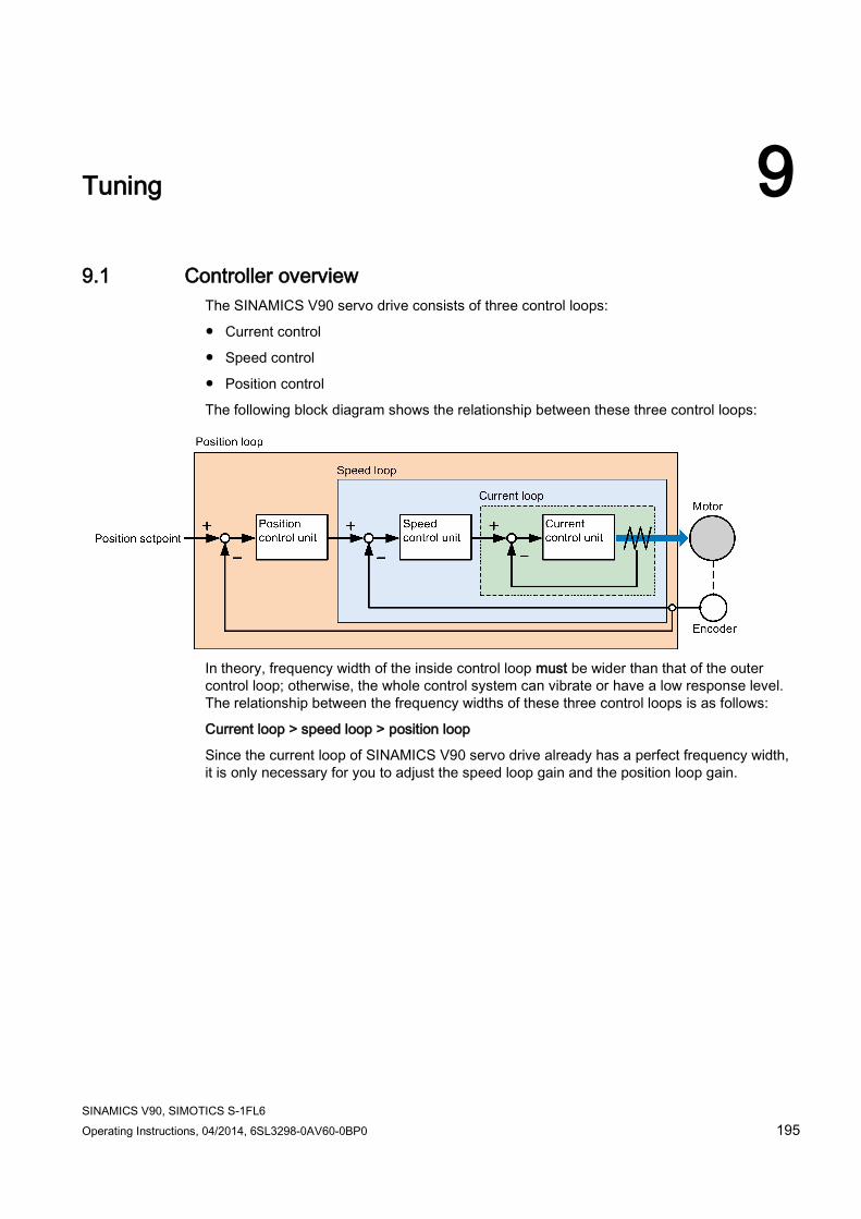
SINAMICS V90, SIMOTICS S-1FL6 Operating Instructions, 04/2014, 6SL3298-0AV60-0BP0 195
Tuning 9 9.1 Controller overview
The SINAMICS V90 servo drive consists of three control loops:
● Current control
● Speed control
● Position control
The following block diagram shows the relationship between these three control loops:
In theory, frequency width of the inside control loop must be wider than that of the outer control loop; otherwise, the whole control system can vibrate or have a low response level. The relationship between the frequency widths of these three control loops is as follows:
Current loop > speed loop > position loop
Since the current loop of SINAMICS V90 servo drive already has a perfect frequency width, it is only necessary for you to adjust the speed loop gain and the position loop gain.
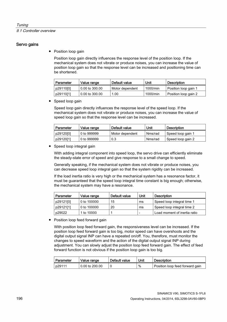
Tuning 9.1 Controller overview
SINAMICS V90, SIMOTICS S-1FL6 196 Operating Instructions, 04/2014, 6SL3298-0AV60-0BP0
Servo gains ● Position loop gain
Position loop gain directly influences the response level of the position loop. If the mechanical system does not vibrate or produce noises, you can increase the value of position loop gain so that the response level can be increased and positioning time can be shortened.
Parameter Value range Default value Unit Description p29110[0] 0.00 to 300.00 Motor dependent 1000/min Position loop gain 1 p29110[1] 0.00 to 300.00 1.00 1000/min Position loop gain 2
● Speed loop gain
Speed loop gain directly influences the response level of the speed loop. If the mechanical system does not vibrate or produce noises, you can increase the value of speed loop gain so that the response level can be increased.
Parameter Value range Default value Unit Description p29120[0] 0 to 999999 Motor dependent Nms/rad Speed loop gain 1 p29120[1] 0 to 999999 0.3 Nms/rad Speed loop gain 2
● Speed loop integral gain
With adding integral component into speed loop, the servo drive can efficiently eliminate the steady-state error of speed and give response to a small change to speed.
Generally speaking, if the mechanical system does not vibrate or produce noises, you can decrease speed loop integral gain so that the system rigidity can be increased.
If the load inertia ratio is very high or the mechanical system has a resonance factor, it must be guaranteed that the speed loop integral time constant is big enough; otherwise, the mechanical system may have a resonance.
Parameter Value range Default value Unit Description p29121[0] 0 to 100000 15 ms Speed loop integral time 1 p29121[1] 0 to 100000 20 ms Speed loop integral time 2 p29022 1 to 10000 1 - Load moment of inertia ratio
● Position loop feed forward gain
With position loop feed forward gain, the responsiveness level can be increased. If the position loop feed forward gain is too big, motor speed can have overshoots and the digital output signal INP can have a repeated on/off. You, therefore, must monitor the changes to speed waveform and the action of the digital output signal INP during adjustment. You can slowly adjust the position loop feed forward gain. The effect of feed forward function is not obvious if the position loop gain is too big.
Parameter Value range Default value Unit Description p29111 0.00 to 200.00 0 % Position loop feed forward gain

Tuning 9.2 First time commissioning mode
SINAMICS V90, SIMOTICS S-1FL6 Operating Instructions, 04/2014, 6SL3298-0AV60-0BP0 197
9.2 First time commissioning mode Responsivity of a machine can be optimized by tuning. The responsivity is reflected by dynamic factor and determined by the servo gains that is set in the servo drive.
The servo gains are set by using a combination of parameters. These parameters influence each other so you must consider the balance between set values when setting these values.
Generally, the responsivity of a machine with high rigidity can be improved by increasing the servo gains; however, if the servo gains of a machine with low rigidity are increased, the machine can vibrate and the responsivity cannot be improved.
NOTICE
Effectiveness of servo gains
The tuning function only uses the first group of servo gains (position loop gain 1, speed loop gain 1 and speed loop integral time 1).
The following tuning functions are available for the SINAMICS V90 servo drive.
Select a tuning mode by setting the parameter p29021:
Parameter Setting value Description Estimation of load inertia
moment ratio p29021 0 (default) Auto tuning is disabled (manual tuning) without changing
servo gains relevant parameters. -
3 Real-time auto tuning for positioning Identify load inertia moment ratio and automatically adjust servo gains when performing single servo drive positioning.
Always estimated
4 Real-time auto tuning for interpolation Identify load inertia moment ratio and automatically adjust servo gains when performing interpolation operation of two or more servo drives.
Always estimated
5 Auto tuning is disabled (manual tuning). All servo gains relevant parameters are set to default values.
-
Tuning with SINAMICS V-ASSISTANT You can also perform tuning with the engineering tool SINAMICS V-ASSISTANT. For more information, refer to SINAMICS V-ASSISTANT Online Help.

Tuning 9.2 First time commissioning mode
SINAMICS V90, SIMOTICS S-1FL6 198 Operating Instructions, 04/2014, 6SL3298-0AV60-0BP0
9.2.1 Basic tuning procedure Proceed as follows to perform tuning for the SINAMICS V90 servo drive:
9.2.2 Configuration of dynamic factor You can configure the dynamic factor of the servo system with the parameter p29020. Higher dynamic factor means higher tracking ability and shorter settling time but also higher possibility of resonance. You should find a desired dynamic factor within a resonance-free range.
31 dynamic factors are available for the SINAMICS V90 servo drive:

Tuning 9.2 First time commissioning mode
SINAMICS V90, SIMOTICS S-1FL6 Operating Instructions, 04/2014, 6SL3298-0AV60-0BP0 199
Dynamic factor (p29020) Machine rigidity
1 Low 2
↑
3 4 5 6 7 8 9 10 11 12 13 14 15 16
Middle 17 18
↓
19 20 21 22 23 24 25 26 27 28 29 30 31 High
If the dynamic factor setting cannot be increased up to the desired level because of machine resonance beyond 100Hz, the function of resonance suppression can be used to suppress machine resonance and thus increase dynamic factor. Refer to Section "Resonance suppression (Page 203)" for detailed information about the function of resonance suppression.

Tuning 9.3 Real-time auto tuning
SINAMICS V90, SIMOTICS S-1FL6 200 Operating Instructions, 04/2014, 6SL3298-0AV60-0BP0
9.3 Real-time auto tuning Real-time auto tuning has two kinds of applications:
● for positioning (p29021=3): adjust servo gains when performing single servo drive positioning.
● for interpolation (p29021=4): adjust servo gains when performing interpolation operation of two or more servo drives. In this case, the tuning pre-control time constant p29028 must be set to an equal value in each drive.
With the real-time auto tuning, the servo drive can automatically estimate the load moment of inertia ratio and set the optimum gains accordingly at real time.
The following servo gains relevant parameters can be set automatically when you choose to use the real-time auto tuning:
Parameter Value range Default Value Unit Description p29022 1 to 10000 1 - Load moment of inertia ratio p29025 0 to 63 13 - Configuration of auto tuning p29110[0] 0.00 to 300.00 Motor
dependent 1000/min Position loop gain 1
p29120[0] 0 to 999999 Motor dependent
Nms/rad Speed loop gain 1
p29121[0] 0 to 100000 15 ms Speed loop integral time 1 p29111 0.00 to 200.00 0.00 % Position loop feed forward gain
Note
After the real-time auto tuning is activated, do not change other auto tuning related control/filter parameters since these parameters can be set automatically and your changes will not be accepted.
Note Pre-conditions for the real-time auto tuning
The real-time auto tuning may not be performed properly if the following conditions are not satisfied: • Time to reach 2000 rpm is the acceleration/deceleration time constant of 5s or less. • Speed is 150 rpm or higher. The ratio of load inertia moment to servo motor inertia
moment is 100 times or less. • The acceleration/deceleration torque is 10% or more of the rated torque.
Under operating conditions that impose sudden disturbance torque during acceleration/deceleration or on a machine that is extremely loose, auto tuning may not function properly, either. In such cases, use the manual tuning to make gain adjustment.

Tuning 9.4 Manual tuning
SINAMICS V90, SIMOTICS S-1FL6 Operating Instructions, 04/2014, 6SL3298-0AV60-0BP0 201
9.4 Manual tuning When the auto tuning cannot reach expected tuning results, you can disable the auto tuning function by setting the parameter p29021 and manually perform tuning:
● p29021=5: auto tuning function is disabled and all control parameters (servo gains) are reset to default values.
● p29021=0: auto tuning function is disabled without changing control parameters (servo gains).

Tuning 9.4 Manual tuning
SINAMICS V90, SIMOTICS S-1FL6 202 Operating Instructions, 04/2014, 6SL3298-0AV60-0BP0
Procedure for manual tuning Follow the procedure below to perform manual tuning:
Note Resonance suppression
For detailed information about the resonance suppression, refer to Section "Resonance suppression (Page 203)".
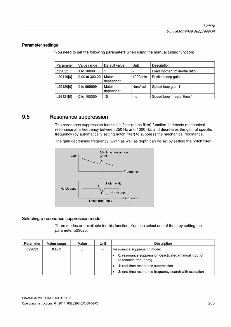
Tuning 9.5 Resonance suppression
SINAMICS V90, SIMOTICS S-1FL6 Operating Instructions, 04/2014, 6SL3298-0AV60-0BP0 203
Parameter settings You need to set the following parameters when using the manual tuning function:
Parameter Value range Default value Unit Description p29022 1 to 10000 1 - Load moment of inertia ratio p29110[0] 0.00 to 300.00 Motor
dependent 1000/min Position loop gain 1
p29120[0] 0 to 999999 Motor dependent
Nms/rad Speed loop gain 1
p29121[0] 0 to 100000 15 ms Speed loop integral time 1
9.5 Resonance suppression The resonance suppression function is filter (notch filter) function. It detects mechanical resonance at a frequency between 250 Hz and 1000 Hz, and decreases the gain of specific frequency (by automatically setting notch filter) to suppress the mechanical resonance.
The gain decreasing frequency, width as well as depth can be set by setting the notch filter:
Selecting a resonance suppression mode Three modes are available for this function. You can select one of them by setting the parameter p29023:
Parameter Value range Value Unit Description
p29023 0 to 2 0 - Resonance suppression mode: • 0: resonance suppression deactivated (manual input of
resonance frequency) • 1: real-time resonance suppression • 2: one-time resonance frequency search with excitation

Tuning 9.5 Resonance suppression
SINAMICS V90, SIMOTICS S-1FL6 204 Operating Instructions, 04/2014, 6SL3298-0AV60-0BP0
Note
Perform manual tuning to increase the responsivity after executing this function.
The real-time resonance suppression can be used together with auto-tuning.
The basic operating sequence to use the function of resonance suppression is shown as follows:
Real-time resonance suppression (p29023=1) When you choose to use the real-time resonance suppression, the servo drive performs real-time detection of the resonance frequency and configures the following notch filter relevant parameters accordingly:
Parameter Value range Value Unit Description
p1662 1 to 2 1 - Current notch filter type: • 1: 2-step lowpass filter • 2: 2-step general filter
p1663 0.5 to 16000 1999 - Natural frequency of current notch filter (2-step lowpass filter or 2-step general filter) denominator.
p1664 0.001 to 10 0.7 - Damp of current notch filter (2-step lowpass filter or 2-step general filter) denominator.

Tuning 9.5 Resonance suppression
SINAMICS V90, SIMOTICS S-1FL6 Operating Instructions, 04/2014, 6SL3298-0AV60-0BP0 205
Parameter Value range Value Unit Description p1665 0.5 to 16000 1999 - Natural frequency of current notch filter (2-step general filter) numerator. p1666 0.001 to 10 0.7 - Damp of current notch filter (2-step general filter) numerator.
One-time resonance frequency search with excitation (p29023=2) Before you use the one-time resonance frequency search with excitation, make sure the load is mounted as required and the servo motor can rotate freely. When you choose to use the one-time resonance frequency search, the servo motor runs for 10 seconds. During this time, the servo drive generates a test signal that helps detect the most powerful mechanical resonance frequency. At the end of this time, the servo drive automatically sets the following notch filter relevant parameters and deactivates the resonance suppression function (p29023=0):
Parameter Value range Value Unit Description
p1662 1 to 2 1 - Current notch filter type: • 1: 2-step lowpass filter • 2: 2-step general filter
p1663 0.5 to 16000 1999 - Natural frequency of current notch filter (2-step lowpass filter or 2-step general filter) denominator.
p1664 0.001 to 10 0.7 - Damp of current notch filter (2-step lowpass filter or 2-step general filter) denominator.
p1665 0.5 to 16000 1999 - Natural frequency of current notch filter (2-step general filter) numerator. p1666 0.001 to 10 0.7 - Damp of current notch filter (2-step general filter) numerator.
Note Notch filter remains active when the resonance suppression function is activated automatically.
You can deactivate the notch filter by setting the parameter p1656: bit 1 = 0.
Manual input of resonance frequency (p29023=0) When both the real-time resonance suppression and the one-time resonance frequency search with excitation cannot reach the suppression effect, you can do the resonance suppression by manually setting the following parameters:
Parameter Value range Value Unit Description
p1662 1 to 2 1 - Current notch filter type: • 1: 2-step lowpass filter • 2: 2-step general filter
p1663 0.5 to 16000 1999 - Natural frequency of current notch filter (2-step lowpass filter or 2-step general filter) denominator.

Tuning 9.6 Gain switching
SINAMICS V90, SIMOTICS S-1FL6 206 Operating Instructions, 04/2014, 6SL3298-0AV60-0BP0
Parameter Value range Value Unit Description p1664 0.001 to 10 0.7 - Damp of current notch filter (2-step lowpass filter or 2-step general filter)
denominator. p1665 0.5 to 16000 1999 - Natural frequency of current notch filter (2-step general filter) numerator. p1666 0.001 to 10 0.7 - Damp of current notch filter (2-step general filter) numerator.
Assume the notch frequency is fsp, notch width is fBB, and notch depth is K, then the filter parameters can be calculated as follows:
p1663=p1665=fsp
p1664=fBB / (2 × fsp)
p1666=(fBB × 10(k/20) )/ (2 × fsp)
9.6 Gain switching
Note
The Gain Switching function is not available in T mode (torque control mode).
The function of auto-tuning must be disabled so that the function of gain switching can be available.
With this function, you can:
● increase the gains during servo lock and decrease gains to reduce noise during rotation.
● increase the gains during settling to shorten the stop settling time.
● switch between two groups of gains using an external signal (G-CHANGE) to ensure stability of the servo system because the load inertia moment ratio varies greatly during a stop (for example, a large load is mounted on a carrier).
Selection of a gain switching mode Five gain switching modes in total are available:
● Gain switching disabled
● Gain switching using digital input signal (G-CHANGE)
● Gain switching using position deviation
● Gain switching using position setpoint frequency
● Gain switching using actual speed
You can select one of the five modes by setting parameter p29130:

Tuning 9.6 Gain switching
SINAMICS V90, SIMOTICS S-1FL6 Operating Instructions, 04/2014, 6SL3298-0AV60-0BP0 207
Parameter Value Description
p29130 0 (default) The function of gain switching is disabled. Only the first group of gains is valid and the function of PI to P switching of speed controller is enabled.
1 Gain switching using digital input signal (G-CHANGE). When G-CHANGE is 0, the first group of gains is selected; when G-CHANGE is 1, the second one is selected.
2 Gain switching using position deviation. In the position control mode, gain switching can be decided by position deviation. If the position deviation is less than preset value, the first group of gains is selected; otherwise, the second one is selected.
3 Gain switching using position setpoint frequency. In the position control mode, gain switching can also be decided by position setpoint frequency. If the position setpoint frequency is less than preset value, the first group of gain is selected; otherwise, the second one is selected.
4 In the speed control mode, gain switching can be decided by actual speed. If the actual speed is below preset value; otherwise, the second one is selected.
9.6.1 Gain switching using an external digital input signal (G-CHANGE)
DI settings ● Position control mode
Signal Pin assignment Setting Description G-CHANGE X8-9 (factory
setting) 0 The first group of gains is selected. 1 The second group of gains is selected.
● Speed control mode
Signal Pin assignment Setting Description G-CHANGE - 0 The first group of gains is selected.
1 The second group of gains is selected.
Parameter settings (p29130 = 1) Parameter Value range Default value Unit Description p29110[0] 0.00 to 300.00 Motor dependent 1000/min Position loop gain 1 p29110[1] 0.00 to 300.00 1.00 1000/min Position loop gain 2 p29120[0] 0 to 999999 Motor dependent Nms/rad Speed loop gain 1 p29120[1] 0 to 999999 0.3 Nms/rad Speed loop gain 2 p29121[0] 0 to 100000 15 ms Speed loop integral time 1

Tuning 9.6 Gain switching
SINAMICS V90, SIMOTICS S-1FL6 208 Operating Instructions, 04/2014, 6SL3298-0AV60-0BP0
Parameter Value range Default value Unit Description p29121[1] 0 to 100000 20 ms Speed loop integral time 2 p29139 8 to 1000 20 ms Time constant to smooth the switching between gain sets
Timing diagram
Note
If the pulse duration is shorter than 10 ms, there is no reaction.
9.6.2 Gain switching using position deviation
Parameter settings (p29130 = 2) Parameter Value range Default value Unit Description p29110[0] 0.00 to 300.00 Motor dependent 1000/min Position loop gain 1 p29110[1] 0.00 to 300.00 1.00 1000/min Position loop gain 2 p29120[0] 0 to 999999 Motor dependent Nms/rad Speed loop gain 1 p29120[1] 0 to 999999 0.3 Nms/rad Speed loop gain 2 p29121[0] 0 to 100000 15 ms Speed loop integral time 1 p29121[1] 0 to 100000 20 ms Speed loop integral time 2 p29131 0 to 2147483647 100 LU Position deviation threshold for automatically triggering
gain switching p29139 8 to 1000 20 ms Time constant to smooth the switching between gain sets

Tuning 9.6 Gain switching
SINAMICS V90, SIMOTICS S-1FL6 Operating Instructions, 04/2014, 6SL3298-0AV60-0BP0 209
Timing diagram
9.6.3 Gain switching using position setpoint frequency
Parameter settings (p29130 = 3) Parameter Value range Setting value Unit Description p29110[0] 0.00 to 300.00 Motor dependent 1000/min Position loop gain 1 p29110[1] 0.00 to 300.00 1.00 1000/min Position loop gain 2 p29120[0] 0 to 999999 Motor dependent Nms/rad Speed loop gain 1 p29120[1] 0 to 999999 0.3 Nms/rad Speed loop gain 2 p29121[0] 0 to 100000 15 ms Speed loop integral time 1 p29121[1] 0 to 100000 20 ms Speed loop integral time 2 p29132 0 to 2147000064 100 1000 LU/min Position setpoint frequency threshold for
automatically triggering gain switching p29139 8 to 1000 20 ms Time constant to smooth the switching between gain
sets
Timing diagram

Tuning 9.7 PI/P switching
SINAMICS V90, SIMOTICS S-1FL6 210 Operating Instructions, 04/2014, 6SL3298-0AV60-0BP0
9.6.4 Gain switching using actual speed
Parameter settings (p29130 = 4) Parameter Value range Setting value Unit Description p29110[0] 0.00 to 300.00 Motor dependent 1000/min Position loop gain 1 p29110[1] 0.00 to 300.00 1.00 1000/min Position loop gain 2 p29120[0] 0 to 999999 Motor dependent Nms/rad Speed loop gain 1 p29120[1] 0 to 999999 0.3 Nms/rad Speed loop gain 2 p29121[0] 0 to 100000 15 ms Speed loop integral time 1 p29121[1] 0 to 100000 20 ms Speed loop integral time 2 p29133 0 to 2147000064 100 rpm Speed threshold for automatically triggering gain
switching p29139 8 to 1000 20 ms Time constant to smooth the switching between gain
sets
Timing diagram
9.7 PI/P switching
Note PI/P switching
Function of PI/P switching is not available for the T mode (torque control mode).
The functions of auto-tuning and gain switching must be disabled so that the function of PI/P switching can be available.
The PI/P switching will respond with a delay time of several milliseconds.
The function of PI/P switching is used to switch from PI (Proportional/Integral) control of speed controller to P (Proportional) control. With this function, you can:

Tuning 9.7 PI/P switching
SINAMICS V90, SIMOTICS S-1FL6 Operating Instructions, 04/2014, 6SL3298-0AV60-0BP0 211
● shorten the position setting time (for the position control mode).
● avoid overshooting of actual speed value during acceleration or deceleration (for the speed control mode).
● avoid unnecessary torque when the target position is at a mechanical limitation (for the position control mode).
Selection of a switching mode for PI/P switching Five switching modes in total are available for PI/P switching:
● using torque setpoint
● using an external digital input signal (G-CHANGE)
● using speed setpoint
● using acceleration setpoint
● using pulse deviation
You can select one of the switching modes by setting parameter p29140:
Parameter Value Description
p29140 0 (default) Disabled. 1 Torque is higher than a parameterizable setting value. 2 Using the digital input signal (G-CHANGE) 3 Speed is higher than a parameterizable setting value. 4 Acceleration is higher than a parameterizable setting value. 5 Pulse deviation is higher than a parameterizable setting value.

Tuning 9.7 PI/P switching
SINAMICS V90, SIMOTICS S-1FL6 212 Operating Instructions, 04/2014, 6SL3298-0AV60-0BP0
Example
Without the function of PI/P switching With the function of PI/P switching Example 1: If the PI/P switching is not used, the speed of the motor may overshoot or undershoot due to torque saturation during acceleration or deceleration. The mode switching function suppresses torque saturation and eliminates the overshooting or undershooting of the motor speed.
Example 2: The function of PI/P switching can be used to suppress overshooting and undershooting when speed loop gain is increased
9.7.1 PI/P switching using torque setpoint When torque setpoint exceeds preset torque value (p29141), the speed loop is switched from PI control to P control.

Tuning 9.7 PI/P switching
SINAMICS V90, SIMOTICS S-1FL6 Operating Instructions, 04/2014, 6SL3298-0AV60-0BP0 213
Parameter settings
Parameter Value range Setting value Unit Description p29140 0 to 5 0 (default) - Switches PI control to P control using torque setpoint p29141 0 to 300 200 (default) % Torque threshold for automatically triggering PI to P
switch p29120[0] 0 to 999999 0.3 (default) Nms/rad Speed loop gain 1 p29121[0] 0 to 100000 15 (default) ms Speed loop integral time 1
Note Speed setpoint
For detailed information about speed setpoint, refer to "Configuring speed setpoint (Page 162)". Torque setpoint
For detailed information about torque setpoint, refer to "Torque setpoint (Page 169)".
9.7.2 PI/P switching using an external digital input signal (G-CHANGE)
DI settings ● Position control mode
Signal Pin assignment Setting Description G-CHANGE X8-9 (factory
setting) 0 The first group of gains is selected. 1 The second group of gains is selected.
● Speed control mode
Signal Pin assignment Setting Description G-CHANGE - 0 The first group of gains is selected.
1 The second group of gains is selected.
Parameter settings
Parameter Value range Setting value Unit Description p29140 0 to 5 0 (default) - Switches PI control to P control using torque setpoint
p29120[0] 0 to 999999 0.3 (default) Nms/rad Speed loop gain 1 p29121[0] 0 to 100000 15 (default) ms Speed loop integral time 1
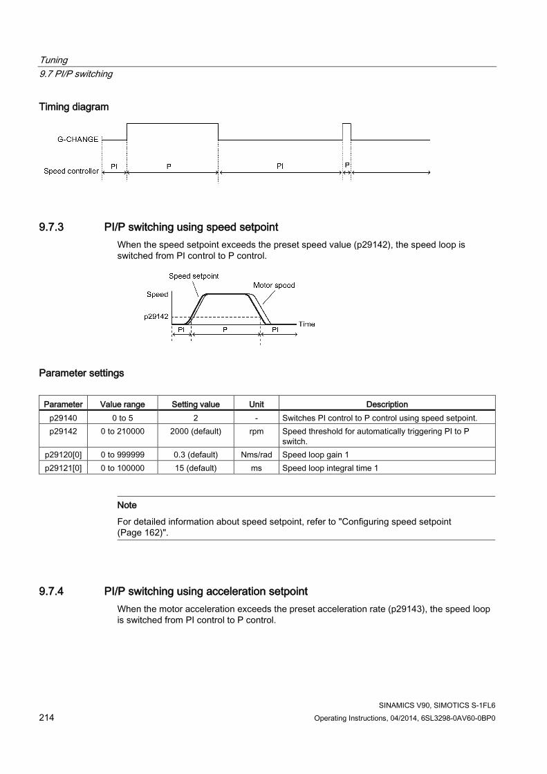
Tuning 9.7 PI/P switching
SINAMICS V90, SIMOTICS S-1FL6 214 Operating Instructions, 04/2014, 6SL3298-0AV60-0BP0
Timing diagram
9.7.3 PI/P switching using speed setpoint When the speed setpoint exceeds the preset speed value (p29142), the speed loop is switched from PI control to P control.
Parameter settings
Parameter Value range Setting value Unit Description p29140 0 to 5 2 - Switches PI control to P control using speed setpoint. p29142 0 to 210000 2000 (default) rpm Speed threshold for automatically triggering PI to P
switch. p29120[0] 0 to 999999 0.3 (default) Nms/rad Speed loop gain 1 p29121[0] 0 to 100000 15 (default) ms Speed loop integral time 1
Note
For detailed information about speed setpoint, refer to "Configuring speed setpoint (Page 162)".
9.7.4 PI/P switching using acceleration setpoint When the motor acceleration exceeds the preset acceleration rate (p29143), the speed loop is switched from PI control to P control.

Tuning 9.7 PI/P switching
SINAMICS V90, SIMOTICS S-1FL6 Operating Instructions, 04/2014, 6SL3298-0AV60-0BP0 215
Parameter settings
Parameter Value range Setting value Unit Description p29140 0 to 5 3 - Switches PI control to P control using acceleration
setpoint. p29143 0 to 30000 20 (default) rev/s2 Acceleration threshold for automatically triggering PI to P
switch. p29120[0] 0 to 999999 0.3 (default) Nms/rad Speed loop gain 1 p29121[0] 0 to 100000 15 (default) ms Speed loop integral time 1
Note Speed setpoint
For detailed information about speed setpoint, refer to "Configuring speed setpoint (Page 162)". Acceleration
For detailed information about acceleration, refer to "Setting fixed position setpoint (Page 147)" of the internal position control mode.
9.7.5 PI/P switching using pulse deviation The speed loop is switched from PI control to P control when the pulse deviation exceeds the preset value (p29144).

Tuning 9.7 PI/P switching
SINAMICS V90, SIMOTICS S-1FL6 216 Operating Instructions, 04/2014, 6SL3298-0AV60-0BP0
Parameter settings
Parameter Value range Setting value Unit Description p29140 0 to 5 4 - Switches PI control to P control using pulse deviation p29144 0 to 2147483647 30000 (default) - Pulse deviation threshold for automatically triggering PI
to P switching p29120[0] 0 to 999999 0.3 (default) Nms/rad Speed loop gain 1 p29121[0] 0 to 100000 15 (default) ms Speed loop integral time 1
Note Speed setpoint
For detailed information about speed setpoint, refer to "Configuring speed setpoint (Page 162)".

SINAMICS V90, SIMOTICS S-1FL6 Operating Instructions, 04/2014, 6SL3298-0AV60-0BP0 217
Parameters 10 10.1 Overview
Parameter number Numbers prefixed with an "r" indicate that parameter is a read-only parameter.
Numbers prefixed with a "P" indicate that the parameter is an editable parameter.
Effective Indicates the conditions for making parameterization effective. Two conditions are possible:
● IM (Immediately): Parameter value becomes effective immediately after changing.
● RE (Reset): Parameter value becomes effective after repower-on.
Can be changed This indicates when the parameter can be changed. Two states are possible:
● U (Run): Can be changed in the "Running" state when the drive is in the servo on state. The "RDY" LED lights up green.
● T (Ready to run): Can be changed in the "Ready" state when the drive is in the servo off state. The "RDY" LED lights up red.
Note
When judging the state of the drive according to the "RDY" LED, ensure that no faults or alarms exist.
Data type Type Description I16 16-bit integer I32 32-bit integer U16 16 bits without sign U32 32 bits without sign Uint16 16-bit unsigned integer Uint32 32-bit unsigned integer Float 32-bit floating point number
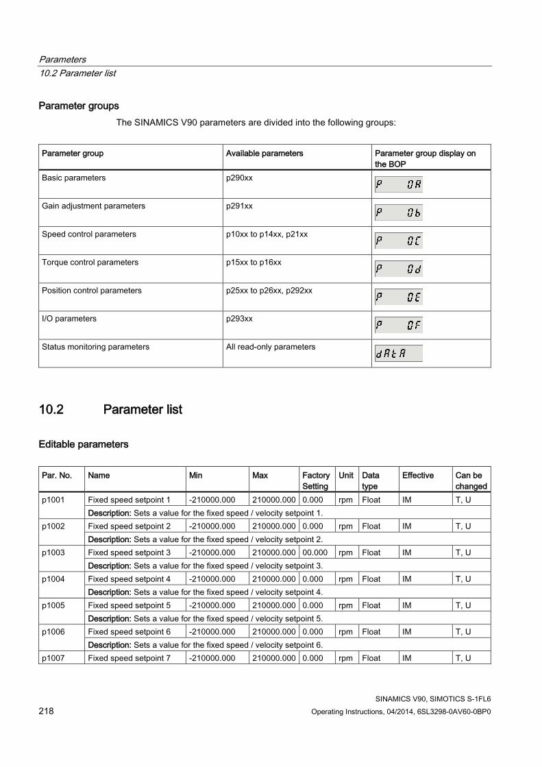
Parameters 10.2 Parameter list
SINAMICS V90, SIMOTICS S-1FL6 218 Operating Instructions, 04/2014, 6SL3298-0AV60-0BP0
Parameter groups The SINAMICS V90 parameters are divided into the following groups:
Parameter group Available parameters Parameter group display on
the BOP Basic parameters p290xx
Gain adjustment parameters p291xx
Speed control parameters p10xx to p14xx, p21xx
Torque control parameters p15xx to p16xx
Position control parameters p25xx to p26xx, p292xx
I/O parameters p293xx
Status monitoring parameters All read-only parameters
10.2 Parameter list
Editable parameters Par. No. Name Min Max Factory
Setting Unit Data
type Effective Can be
changed p1001
Fixed speed setpoint 1 -210000.000 210000.000 0.000 rpm Float IM T, U Description: Sets a value for the fixed speed / velocity setpoint 1.
p1002 Fixed speed setpoint 2 -210000.000 210000.000 0.000 rpm Float IM T, U Description: Sets a value for the fixed speed / velocity setpoint 2.
p1003
Fixed speed setpoint 3 -210000.000 210000.000 00.000 rpm Float IM T, U Description: Sets a value for the fixed speed / velocity setpoint 3.
p1004
Fixed speed setpoint 4 -210000.000 210000.000 0.000 rpm Float IM T, U Description: Sets a value for the fixed speed / velocity setpoint 4.
p1005
Fixed speed setpoint 5 -210000.000 210000.000 0.000 rpm Float IM T, U Description: Sets a value for the fixed speed / velocity setpoint 5.
p1006
Fixed speed setpoint 6 -210000.000 210000.000 0.000 rpm Float IM T, U Description: Sets a value for the fixed speed / velocity setpoint 6.
p1007 Fixed speed setpoint 7 -210000.000 210000.000 0.000 rpm Float IM T, U

Parameters 10.2 Parameter list
SINAMICS V90, SIMOTICS S-1FL6 Operating Instructions, 04/2014, 6SL3298-0AV60-0BP0 219
Par. No. Name Min Max Factory Setting
Unit Data type
Effective Can be changed
Description: Sets a value for the fixed speed / velocity setpoint 7. p1058
Jog 1 speed setpoint 0.00 210000.000 100.00 rpm Float IM T Description: Sets the speed/velocity for jog 1. Jogging is level-triggered and allows the motor to be incrementally moved. Note: The parameter values displayed on the BOP are integers.
p1082 * Description: Maximum speed
0.000 210000.000 1500.000
rpm Float IM T
Description: Sets the highest possible speed. Notice: After the value has been modified, no further parameter modifications can be made. Note: The parameter values displayed on the BOP are integers. The parameter applies for both motor directions. The parameter has a limiting effect and is the reference quantity for all ramp-up and ramp-down times (e.g. down ramps, ramp-function generator and motor potentiometer). The range of the parameter is different when connect with different motors.
p1083 * Speed limit in positive direction of rotation
0.000 210000.000 210000.000
rpm Float IM T, U
Description: Sets the maximum speed for the positive direction. Note: The parameter values displayed on the BOP are integers.
p1086 * Speed limit in negative direction of rotation
-210000.000 0.000 -210000.000
rpm Float IM T, U
Description: Sets the speed limit for the negative direction. Note: The parameter values displayed on the BOP are integers.
p1115 Ramp-function generator selection
0 1 0 - I16 IM T
Description: Sets the ramp-function generator type. Note: Another ramp-function generator type can only be selected when the motor is at a standstill.
p1120 Ramp-function generator ramp-up time
0.000 999999.000 1 s Float IM T, U
Description: The ramp-function generator ramps-up the speed setpoint from standstill (setpoint = 0) up to the maximum speed (p1082) in this time. Dependency: Refer to p1082
p1121 Ramp-function generator ramp-down time
0.000 999999.000 1 s Float IM T, U
Description: Sets the ramp-down time for the ramp-function generator. The ramp-function generator ramps-down the speed setpoint from the maximum speed (p1082) down to standstill (setpoint = 0) in this time. Further, the ramp-down time is always effective for OFF1. Dependency: Refer to p1082
p1130 Ramp-function generator initial rounding-off time
0.000 30.000 0.000 s Float IM T, U
Description: Sets the initial rounding-off time for the extended ramp generator. The value applies to ramp-up and ramp-down. Note: Rounding-off times avoid an abrupt response and prevent damage to the mechanical system.

Parameters 10.2 Parameter list
SINAMICS V90, SIMOTICS S-1FL6 220 Operating Instructions, 04/2014, 6SL3298-0AV60-0BP0
Par. No. Name Min Max Factory Setting
Unit Data type
Effective Can be changed
p1131 Ramp-function generator final rounding-off time
0.000 30.000 0.000 s Float IM T, U
Description: Sets the final rounding-off time for the extended ramp generator. The value applies to ramp-up and ramp-down. Note: Rounding-off times avoid an abrupt response and prevent damage to the mechanical system.
p1215 * Motor holding brake configuration
0 3 0 - I16 IM T
Description: Sets the holding brake configuration. Dependency: Refer to p1216, p1217, p1226, p1227, p1228 Caution: For the setting p1215 = 0, if a brake is used, it remains closed. If the motor moves, this will destroy the brake. Notice: If p1215 was set to 1 or if p1215 was set to 3, then when the pulses are suppressed, the brake is closed even if the motor is still rotating. Note: If a holding brake integrated in the motor is used, then it is not permissible that p1215 is set to 3. The parameter can only be set to zero when the pulses are inhibited.
p1216 * Motor holding brake opening time
0 10000 100 ms Float IM T, U
Description: Sets the time to open the motor holding brake. After controlling the holding brake (opens), the speed/velocity setpoint remains at zero for this time. After this, the speed/velocity setpoint is enabled. Dependency: Refer to p1215, p1217 Note: For a motor with integrated brake, this time is pre-assigned the value saved in the motor. For p1216 = 0 ms, the monitoring and the message A7931 "Brake does not open" are deactivated.
p1217 * Motor holding brake closing time
0 10000 100 ms Float IM T, U
Description: Sets the time to apply the motor holding brake. After OFF1 or OFF3 and the holding brake is controlled (the brake closes), then the drive remains closed-loop controlled for this time stationary with a speed setpoint/velocity setpoint of zero. The pulses are suppressed when the time expires. Dependency: Refer to p1215, p1216 Note: For a motor with integrated brake, this time is pre-assigned the value saved in the motor. For p1217 = 0 ms, the monitoring and the message A07932 "Brake does not close" are deactivated.
p1226 Threshold for zero speed detection
0.00 210000.00 20.00 rpm Float IM T, U
Description: Sets the speed threshold for the standstill identification. Acts on the actual value and setpoint monitoring. When braking with OFF1 or OFF3, when the threshold is undershot, standstill is identified. The following applies when the brake control is activated: When the threshold is undershot, the brake control is started and the system waits for the brake closing time in p1217. The pulses are then suppressed. If the brake control is not activated, the following applies: When the threshold is undershot, the pulses are suppressed and the drive coasts down. Dependency: Refer to p1215, p1216, p1217, p1227 Notice: For reasons relating to the compatibility to earlier firmware versions, a parameter value of zero in indices 1 to 31 is overwritten with the parameter value in index 0 when the drive boots.

Parameters 10.2 Parameter list
SINAMICS V90, SIMOTICS S-1FL6 Operating Instructions, 04/2014, 6SL3298-0AV60-0BP0 221
Par. No. Name Min Max Factory Setting
Unit Data type
Effective Can be changed
Note: Standstill is identified in the following cases: - The speed actual value falls below the speed threshold in p1226 and the time started after this in p1228 has expired. - The speed setpoint falls below the speed threshold in p1226 and the time started after this in p1227 has expired. The actual value sensing is subject to measuring noise. For this reason, standstill cannot be detected if the speed threshold is too low.
p1227 Zero speed detection monitoring time
0.000 300.000 300.000 s Float IM T, U
Description: Sets the monitoring time for the standstill identification. When braking with OFF1 or OFF3, standstill is identified after this time has expired, after the setpoint speed has fallen below p1226. After this, the brake control is started, the system waits for the closing time in p1217 and then the pulses are suppressed. Dependency: Refer to p1215, p1216, p1217, p1226 Notice: The setpoint is not equal to zero dependent on the selected value. This can therefore cause the monitoring time in p1227 to be exceeded. In this case, for a driven motor, the pulses are not suppressed.. Note: Standstill is identified in the following cases: - The speed actual value falls below the speed threshold in p1226 and the time started after this in p1228 has expired. - The speed setpoint falls below the speed threshold in p1226 and the time started after this in p1227 has expired. For p1227 = 300.000 s, the following applies: Monitoring is de-activated. For p1227 = 0.000 s, the following applies: With OFF1 or OFF3 and a ramp-down time = 0, the pulses are immediately suppressed and the motor "coasts" down.
p1228 Pulse suppression delay time
0.000 299.000 0.000 s Float IM T, U
Description: Sets the delay time for pulse suppression. After OFF1 or OFF3, the pulses are canceled, if at least one of the following conditions is fulfilled: - The speed actual value falls below the threshold in p1226 and the time started after this in p1228 has expired. - The speed setpoint falls below the threshold in p1226 and the time started after this in p1227 has expired. Dependency: Refer to p1226, p1227 Notice: When the motor holding brake is activated, pulse cancellation is additionally delayed by the brake closing time (p1217).
p1414 Speed setpoint filter activation
0000 bin 0011 bin 0000 bin
- U16 IM T, U
Description: Setting for activating/de-activating the speed setpoint filter. Dependency: The individual speed setpoint filters are parameterized as of p1415. Note: The drive unit displays the value in hex format. To know the logic (high/low) assignment to each bit, you must convert the hex number to the binary number, for example, FF (hex) = 11111111 (bin).
p1415 Speed setpoint filter 1 type
0 2 0 - I16 IM T, U
Description: Sets the type for speed setpoint filter 1.

Parameters 10.2 Parameter list
SINAMICS V90, SIMOTICS S-1FL6 222 Operating Instructions, 04/2014, 6SL3298-0AV60-0BP0
Par. No. Name Min Max Factory Setting
Unit Data type
Effective Can be changed
Dependency: PT1 low pass: p1416 PT2 low pass: p1417, p1418 General filter: p1417 ... p1420
p1416 Speed setpoint filter 1 time constant
0.00 5000.00 0.00 ms Float IM T, U
Description: Sets the time constant for the speed setpoint filter 1 (PT1). Dependency: Refer to p1414, p1415 Note: This parameter is only effective if the filter is set as a PT1 low pass.
p1417 Speed setpoint filter 1 denominator natural frequency
0.5 16000.0 1999.0 Hz Float IM T, U
Description: Sets the denominator natural frequency for speed setpoint filter 1(PT2, general filter). Dependency: Refer to p1414, p1415 Note: This parameter is only effective if the speed filter is parameterized as a PT2 low pass or as general filter. The filter is only effective if the natural frequency is less than half of the sampling frequency.
p1418 Speed setpoint filter 1 denominator damping
0.001 10.000 0.700 - Float IM T, U
Description: Sets the denominator damping for speed setpoint filter 1 (PT2, general filter). Dependency: Refer to p1414, p1415 Note: This parameter is only effective if the speed filter is parameterized as a PT2 low pass or as general filter.
p1419 Speed setpoint filter 1 numerator natural frequency
0.5 16000.0 1999.0 Hz Float IM T, U
Description: Sets the numerator natural frequency for speed setpoint filter 1 (general filter). Dependency: Refer to p1414, p1415 Note: This parameter is only effective if the speed filter is set as a general filter. The filter is only effective if the natural frequency is less than half of the sampling frequency.
p1420 Speed setpoint filter 1 numerator damping
0.000 10.000 0.700 - Float IM T, U
Description: Sets the numerator damping for speed setpoint filter 1 (general filter). Dependency: Refer to p1414, p1415 Note: This parameter is only effective if the speed filter is set as a general filter.
p1421 Speed setpoint filter 2 type
0 2 0 - I16 IM T, U
Description: Sets the type for speed setpoint filter 2. Dependency: PT1 low pass: p1422 PT2 low pass: p1423, p1424 General filter: p1423 ... p1426
p1422 Speed setpoint filter 2 time constant
0.00 5000.00 0.00 ms Float IM T, U
Description: Sets the time constant for the speed setpoint filter 2 (PT1).

Parameters 10.2 Parameter list
SINAMICS V90, SIMOTICS S-1FL6 Operating Instructions, 04/2014, 6SL3298-0AV60-0BP0 223
Par. No. Name Min Max Factory Setting
Unit Data type
Effective Can be changed
Dependency: Refer to p1414, p1421 Note: This parameter is only effective if the speed filter is set as a PT1 low pass.
p1423 Speed setpoint filter 2 denominator natural frequency
0.5 16000.0 1999.0 Hz Float IM T, U
Description: Sets the denominator natural frequency for speed setpoint filter 2 (PT2, general filter). Dependency: Refer to p1414, p1421 Note: This parameter is only effective if the speed filter is parameterized as a PT2 low pass or as general filter. The filter is only effective if the natural frequency is less than half of the sampling frequency.
p1424 Speed setpoint filter 2 denominator damping
0.001 10.000 0.700 - Float IM T, U
Description: Sets the denominator damping for speed setpoint filter 2 (PT2, general filter). Dependency: Refer to p1414, p1421 Note: This parameter is only effective if the speed filter is parameterized as a PT2 low pass or as general filter.
p1425 Speed setpoint filter 2 numerator natural frequency
0.5 16000.0 1999.0 Hz Float IM T, U
Description: Sets the numerator natural frequency for speed setpoint filter 2 (general filter). Dependency: Refer to p1414, p1421 Note: This parameter is only effective if the speed filter is set as a general filter. The filter is only effective if the natural frequency is less than half of the sampling frequency.
p1426 Speed setpoint filter 2 numerator damping
0.000 10.000 0.700 - Float IM T, U
Description: Sets the numerator damping for speed setpoint filter 2 (general filter). Dependency: Refer to p1414, p1421 Note: This parameter is only effective if the speed filter is set as a general filter.
p1520 * Torque limit upper -1000000.00 20000000.00
0.00 Nm Float IM T, U
Description: Sets the fixed upper torque limit. Danger: Negative values when setting the upper torque limit (p1520 < 0) can result in the motor accelerating in an uncontrollable fashion. Notice: The maximum value depends on the maximum torque of the connected motor.
p1521 * Torque limit lower -20000000.00 1000000.00 0.00 Nm Float IM T, U Description: Sets the fixed lower torque limit. Danger: Positive values when setting the lower torque limit (p1521 > 0) can result in the motor accelerating in an uncontrollable fashion. Notice: The maximum value depends on the maximum torque of the connected motor.
p1656 * Activates current setpoint filter
0000 bin 0011 bin 0011 bin
- U16 IM T, U
Description: Setting for activating/de-activating the current setpoint filter. Dependency: The individual current setpoint filters are parameterized as of p1657.

Parameters 10.2 Parameter list
SINAMICS V90, SIMOTICS S-1FL6 224 Operating Instructions, 04/2014, 6SL3298-0AV60-0BP0
Par. No. Name Min Max Factory Setting
Unit Data type
Effective Can be changed
Note: If not all of the filters are required, then the filters should be used consecutively starting from filter 1. The drive unit displays the value in hex format. To know the logic (high/low) assignment to each bit, you must convert the hex number to the binary number, for example, FF (hex) = 11111111 (bin).
p1657 * Current setpoint filter 1 type
1 2 1 - I16 IM T, U
Description: Sets the current setpoint filter 1 as low pass (PT2) or general 2nd order filter. Dependency: The current setpoint filter 1 is activated via p1656.0 and parameterized via p1657 ... p1661. Note: For a general 2nd-order filter, by inserting the same natural frequency in both the numerator and in the denominator, i.e. bandstop frequency, a bandstop filter is implemented. If the numerator damping of zero is selected, the bandstop frequency is completely suppressed. The denominator damping can be determined from the equation for the 3 dB bandwidth: f_3dB bandwidth = 2 * D_denominator * f_bandstop frequency
p1658 * Current setpoint filter 1 denominator natural frequency
0.5 16000.0 1000.0 Hz Float IM T, U
Description: Sets the denominator natural frequency for current setpoint filter 1 (PT2, general filter). Dependency: The current setpoint filter 1 is activated via p1656.0 and parameterized via p1657 ... p1661.
p1659 * Current setpoint filter 1 denominator damping
0.001 10.000 0.700 - Float IM T, U
Description: Sets the denominator damping for current setpoint filter 1. Dependency: The current setpoint filter 1 is activated via p1656.0 and parameterized via p1657 ... p1661.
p1660 Current setpoint filter 1 numerator natural frequency
0.5 16000.0 1000.0 Hz Float IM T, U
Description: Sets the numerator natural frequency for current setpoint filter 1 (general filter). Dependency: The current setpoint filter 1 is activated via p1656.0 and parameterized via p1657 ... p1661.
p1661 Current setpoint filter 1 numerator damping
0.000 10.000 0.700 - Float IM T, U
Description: Sets the numerator damping for current setpoint filter 1. Dependency: The current setpoint filter 1 is activated via p1656.0 and parameterized via p1657 ... p1661.
p1662 Current setpoint filter 2 type
1 2 2 - I16 IM T, U
Description: Sets the current setpoint filter 2 as low pass (PT2) or general 2nd order filter. Dependency: Current setpoint filter 2 is activated via p1656.1 and parameterized via p1662 ... p1666. Note: For a general 2nd-order filter, by inserting the same natural frequency in both the numerator and in the denominator, i.e. bandstop frequency, a bandstop filter is implemented. If the numerator damping of zero is selected, the bandstop frequency is completely suppressed. The denominator damping can be determined from the equation for the 3 dB bandwidth: f_3dB bandwidth = 2 * D_denominator * f_bandstop frequency
p1663 Current setpoint filter 2 denominator natural frequency
0.5 16000.0 500.0 Hz Float IM T, U
Description: Sets the denominator natural frequency for current setpoint filter 2 (PT2, general filter). Dependency: Current setpoint filter 2 is activated via p1656.1 and parameterized via p1662 ... p1666.
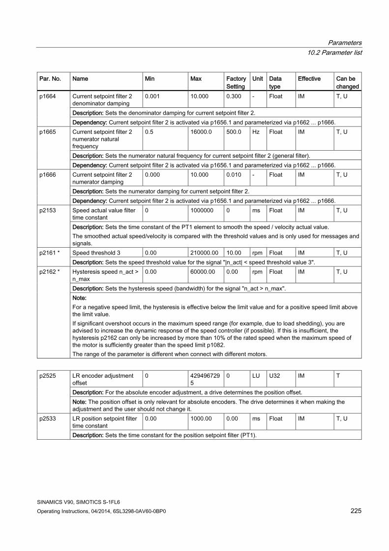
Parameters 10.2 Parameter list
SINAMICS V90, SIMOTICS S-1FL6 Operating Instructions, 04/2014, 6SL3298-0AV60-0BP0 225
Par. No. Name Min Max Factory Setting
Unit Data type
Effective Can be changed
p1664 Current setpoint filter 2 denominator damping
0.001 10.000 0.300 - Float IM T, U
Description: Sets the denominator damping for current setpoint filter 2. Dependency: Current setpoint filter 2 is activated via p1656.1 and parameterized via p1662 ... p1666.
p1665 Current setpoint filter 2 numerator natural frequency
0.5 16000.0 500.0 Hz Float IM T, U
Description: Sets the numerator natural frequency for current setpoint filter 2 (general filter). Dependency: Current setpoint filter 2 is activated via p1656.1 and parameterized via p1662 ... p1666.
p1666
Current setpoint filter 2 numerator damping
0.000 10.000 0.010 - Float IM T, U
Description: Sets the numerator damping for current setpoint filter 2. Dependency: Current setpoint filter 2 is activated via p1656.1 and parameterized via p1662 ... p1666.
p2153 Speed actual value filter time constant
0 1000000 0 ms Float IM T, U
Description: Sets the time constant of the PT1 element to smooth the speed / velocity actual value. The smoothed actual speed/velocity is compared with the threshold values and is only used for messages and signals.
p2161 * Speed threshold 3 0.00 210000.00 10.00 rpm Float IM T, U Description: Sets the speed threshold value for the signal "|n_act| < speed threshold value 3".
p2162 * Hysteresis speed n_act > n_max
0.00 60000.00 0.00 rpm Float IM T, U
Description: Sets the hysteresis speed (bandwidth) for the signal "n_act > n_max". Note: For a negative speed limit, the hysteresis is effective below the limit value and for a positive speed limit above the limit value. If significant overshoot occurs in the maximum speed range (for example, due to load shedding), you are advised to increase the dynamic response of the speed controller (if possible). If this is insufficient, the hysteresis p2162 can only be increased by more than 10% of the rated speed when the maximum speed of the motor is sufficiently greater than the speed limit p1082. The range of the parameter is different when connect with different motors.
p2525
LR encoder adjustment offset
0 4294967295
0 LU U32 IM T
Description: For the absolute encoder adjustment, a drive determines the position offset. Note: The position offset is only relevant for absolute encoders. The drive determines it when making the adjustment and the user should not change it.
p2533 LR position setpoint filter time constant
0.00 1000.00 0.00 ms Float IM T, U
Description: Sets the time constant for the position setpoint filter (PT1).

Parameters 10.2 Parameter list
SINAMICS V90, SIMOTICS S-1FL6 226 Operating Instructions, 04/2014, 6SL3298-0AV60-0BP0
Note: The effective Kv factor (position loop gain) is reduced with the filter. This allows a softer control behavior with improved tolerance with respect to noise/disturbances. Applications: - Reduces the pre-control dynamic response. - Jerk limiting.
p2542 *
LR standstill window 0 2147483647
1000 LU U32 IM T, U
Description: Sets the standstill window for the standstill monitoring function. After the standstill monitoring time expires, it is cyclically checked whether the difference between the setpoint and actual position is located within the standstill window and, if required, an appropriate fault is output. Value = 0: The standstill monitoring is deactivated. Dependency: Refer to: p2543, p2544, and F07450 Note: The following applies for the setting of the standstill and positioning window: Standstill window (p2542) ≥ positioning window (p2544)
p2543 * LR standstill monitoring time
0.00 100000.00 200.00 ms Float IM T, U
Description: Sets the standstill monitoring time for the standstill monitoring function. After the standstill monitoring time expires, it is cyclically checked whether the difference between the setpoint and actual position is located within the standstill window and, if required, an appropriate fault is output. Dependency: Refer to: p2542, p2545, and F07450 Note: The following applies for the setting of the standstill and positioning monitoring time: Standstill monitoring time (p2543) ≤ positioning monitoring time (p2545)
p2544 * LR positioning window 0 2147483647
40 LU U32 IM T, U
Description: Sets the positioning window for the positioning monitoring function. After the positioning monitoring time expires, it is checked once as to whether the difference between the setpoint and actual position lies within the positioning window and if required an appropriate fault is output. Value = 0 --> The positioning monitoring function is de-activated. Dependency: Refer to F07451. Note: The following applies for the setting of the standstill and positioning window: Standstill window (p2542) ≥ positioning window (p2544)
p2545 * LR positioning monitoring time
0.00 100000.00 1000.00 ms Float IM T, U
Description: Sets the positioning monitoring time for the positioning monitoring. After the positioning monitoring time expires, it is checked once as to whether the difference between the setpoint and actual position lies within the positioning window and if required an appropriate fault is output. Dependency: The range of p2545 depends on p2543. Refer to: p2543, p2544, F07451 Note: The tolerance bandwidth is intended to prevent the dynamic following error monitoring incorrectly responding due to operational control sequences (for example, during load surges).
p2546 * LR dynamic following error monitoring tolerance
0 2147483647
1000 LU U32 IM T, U
Description: Sets the tolerance for the dynamic following error monitoring. If the dynamic following error (r2563) exceeds the selected tolerance, then an appropriate fault is output. Value = 0 --> The dynamic following error monitoring is de-activated. Dependency: Refer to r2563, F07452

Parameters 10.2 Parameter list
SINAMICS V90, SIMOTICS S-1FL6 Operating Instructions, 04/2014, 6SL3298-0AV60-0BP0 227
Note: The tolerance bandwidth is intended to prevent the dynamic following error monitoring incorrectly responding due to operational control sequences (e.g. during load surges).
p2572 ** IPOS maximum acceleration
1 2000000 Motor dependent
1000 LU/s²
U32 IM T
Description: Sets the maximum acceleration for the "basic positioner" function (IPOS). Note: The maximum acceleration appears to exhibit jumps (without jerk). "Traversing blocks" operating mode: The programmed acceleration override acts on the maximum acceleration. "Direct setpoint input/MDI" mode: The acceleration override is effective. "Jog" and "search for reference" modes: No acceleration override is active. The axis starts with the maximum acceleration.
p2573 ** IPOS maximum deceleration
1 2000000 Motor dependent
1000 LU/s²
U32 IM T
Description: Sets the maximum deceleration for the "basic positioner" function (IPOS). Note: The maximum deceleration appears to exhibit jumps (without jerk). "Traversing blocks" operating mode: The programmed deceleration override acts on the maximum deceleration. "Direct setpoint input/MDI" mode: The deceleration override is effective. "Jog" and "search for reference" modes: No deceleration override is effective. The axis brakes with the maximum deceleration.
p2580 EPOS software limit switch minus
-2147482648 2147482647
-2147482648
LU I32 IM T, U
Description: Sets the software limit switch in the negative direction of travel. Dependency: Refer to p2581, p2582
p2581 EPOS software limit switch plus
-2147482648 2147482647
2147482647
LU I32 IM T, U
Description: Sets the software limit switch in the positive direction of travel. Dependency: Refer to p2580, p2582
p2582 EPOS software limit switch activation
- - 0 - U32/Binary
IM T
Description: Sets the signal source to activate the "software limit switch". Dependency: Refer to p2580, p2581 Caution: Software limit switch effective: - Axis is referenced. Software limit switch ineffective: - Modulo correction active. - Search for reference is executed.
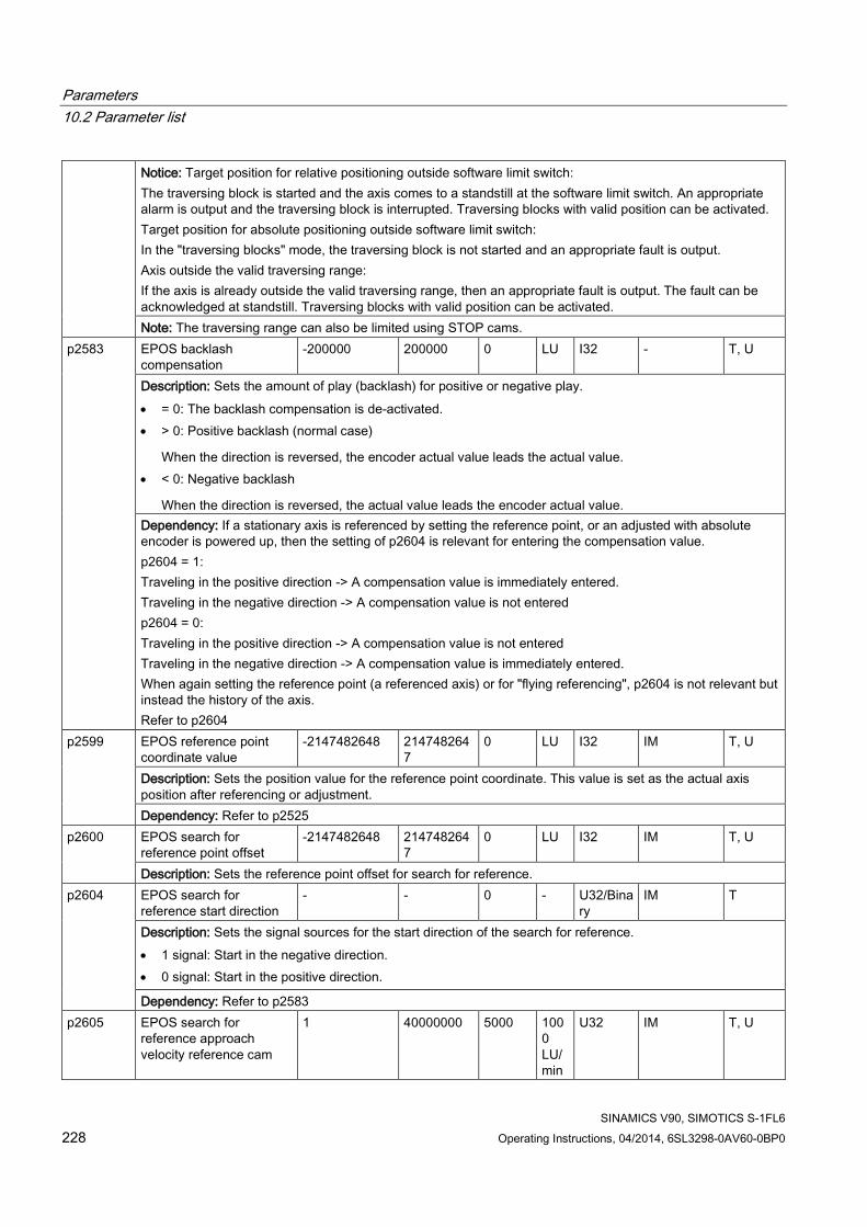
Parameters 10.2 Parameter list
SINAMICS V90, SIMOTICS S-1FL6 228 Operating Instructions, 04/2014, 6SL3298-0AV60-0BP0
Notice: Target position for relative positioning outside software limit switch: The traversing block is started and the axis comes to a standstill at the software limit switch. An appropriate alarm is output and the traversing block is interrupted. Traversing blocks with valid position can be activated. Target position for absolute positioning outside software limit switch: In the "traversing blocks" mode, the traversing block is not started and an appropriate fault is output. Axis outside the valid traversing range: If the axis is already outside the valid traversing range, then an appropriate fault is output. The fault can be acknowledged at standstill. Traversing blocks with valid position can be activated. Note: The traversing range can also be limited using STOP cams.
p2583 EPOS backlash compensation
-200000 200000 0 LU I32 - T, U
Description: Sets the amount of play (backlash) for positive or negative play. • = 0: The backlash compensation is de-activated. • > 0: Positive backlash (normal case)
When the direction is reversed, the encoder actual value leads the actual value. • < 0: Negative backlash
When the direction is reversed, the actual value leads the encoder actual value. Dependency: If a stationary axis is referenced by setting the reference point, or an adjusted with absolute encoder is powered up, then the setting of p2604 is relevant for entering the compensation value. p2604 = 1: Traveling in the positive direction -> A compensation value is immediately entered. Traveling in the negative direction -> A compensation value is not entered p2604 = 0: Traveling in the positive direction -> A compensation value is not entered Traveling in the negative direction -> A compensation value is immediately entered. When again setting the reference point (a referenced axis) or for "flying referencing", p2604 is not relevant but instead the history of the axis. Refer to p2604
p2599 EPOS reference point coordinate value
-2147482648 2147482647
0 LU I32 IM T, U
Description: Sets the position value for the reference point coordinate. This value is set as the actual axis position after referencing or adjustment. Dependency: Refer to p2525
p2600 EPOS search for reference point offset
-2147482648 2147482647
0 LU I32 IM T, U
Description: Sets the reference point offset for search for reference. p2604 EPOS search for
reference start direction - - 0 - U32/Bina
ry IM T
Description: Sets the signal sources for the start direction of the search for reference. • 1 signal: Start in the negative direction. • 0 signal: Start in the positive direction.
Dependency: Refer to p2583 p2605 EPOS search for
reference approach velocity reference cam
1 40000000 5000 1000 LU/min
U32 IM T, U
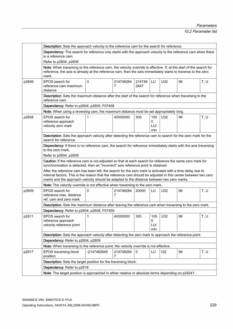
Parameters 10.2 Parameter list
SINAMICS V90, SIMOTICS S-1FL6 Operating Instructions, 04/2014, 6SL3298-0AV60-0BP0 229
Description: Sets the approach velocity to the reference cam for the search for reference. Dependency: The search for reference only starts with the approach velocity to the reference cam when there is a reference cam. Refer to p2604, p2606 Note: When traversing to the reference cam, the velocity override is effective. If, at the start of the search for reference, the axis is already at the reference cam, then the axis immediately starts to traverse to the zero mark.
p2606 EPOS search for reference cam maximum distance
0 2147482647
2147482647
LU U32 IM T, U
Description: Sets the maximum distance after the start of the search for reference when traversing to the reference cam. Dependency: Refer to p2604, p2605, F07458 Note: When using a reversing cam, the maximum distance must be set appropriately long.
p2608 EPOS search for reference approach velocity zero mark
1 40000000 300 1000 LU/min
U32 IM T, U
Description: Sets the approach velocity after detecting the reference cam to search for the zero mark for the search for reference. Dependency: If there is no reference cam, the search for reference immediately starts with the axis traversing to the zero mark. Refer to p2604, p2609 Caution: If the reference cam is not adjusted so that at each search for reference the same zero mark for synchronization is detected, then an "incorrect" axis reference point is obtained. After the reference cam has been left, the search for the zero mark is activated with a time delay due to internal factors. This is the reason that the reference cam should be adjusted in this center between two zero marks and the approach velocity should be adapted to the distance between two zero marks. Note: The velocity override is not effective when traversing to the zero mark.
p2609 EPOS search for reference max. distance ref. cam and zero mark
0 2147482647
20000 LU U32 IM T, U
Description: Sets the maximum distance after leaving the reference cam when traversing to the zero mark. Dependency: Refer to p2604, p2608, F07459
p2611 EPOS search for reference approach velocity reference point
1 40000000 300 1000 LU/min
U32 IM T, U
Description: Sets the approach velocity after detecting the zero mark to approach the reference point. Dependency: Refer to p2604, p2609 Note: When traversing to the reference point, the velocity override is not effective.
p2617 EPOS traversing block position
-2147482648 2147482647
0 LU I32 IM T, U
Description: Sets the target position for the traversing block. Dependency: Refer to p2618 Note: The target position is approached in either relative or absolute terms depending on p29241.

Parameters 10.2 Parameter list
SINAMICS V90, SIMOTICS S-1FL6 230 Operating Instructions, 04/2014, 6SL3298-0AV60-0BP0
p2618 EPOS traversing block velocity
1 40000000 600 1000 LU/min
I32 IM T, U
Description: Sets the velocity for the traversing block. Dependency: The number of indices depends on p2615. Refer to p2617 Note: The velocity can be influenced using the velocity override (p2646).
p29000 * Motor ID 0 54251 0 - U16 RE T Description: Motor type number is printed on the motor rating plate as motor ID. For a motor with an incremental encoder, users need to manually input the parameter value, ranging from 18 to 39. For a motor with an absolute encoder, the drive automatically reads the parameter value, ranging from 10009 to 10048.
p29001 Reversal of motor direction
0 1 0 - I16 RE T
Description: Reversal of motor running direction. By default, CW is the positive direction while CCW the negative direction. After changing of p29001, reference point will lost, A7461 will remind user to referencing again. • 0: No reversal • 1: Reverse
p29002 BOP display selection 0 4 0 - I16 IM U Description: Selection of BOP operating display. • 0: Actual speed (default) • 1: DC voltage • 2: Actual torque • 3: Actual position • 4: Position offset
p29003 Control mode 0 8 0 - I16 RE T Description: Selection of control mode. • 0: Position control with pulse train input (PTI) • 1: Internal position control (IPos) • 2: Speed control (S) • 3: Torque control (T) • 4: Control change mode: PTI/S • 5: Control change mode: IPos/S • 6: Control change mode: PTI/T • 7: Control change mode: IPos/T • 8: Control change mode: S/T
Note: The compound control mode can be controlled by the digital input signal C-MODE. When DI10 (C-MODE) is 0, the first control mode of control change mode is selected; otherwise, the second one is selected.
p29004
RS485 address 0 31 0 - U16 RE T Description: Configuration of the RS485 bus address. The RS485 bus is used to transfer current absolute position of the servo drive to the controller/PLC.

Parameters 10.2 Parameter list
SINAMICS V90, SIMOTICS S-1FL6 Operating Instructions, 04/2014, 6SL3298-0AV60-0BP0 231
p29005
Braking resistor capacity percentage alarm threshold
1 100 100 % Float - T
Description: Alarm triggering threshold for the capacity of the internal braking resistor. Alarm number: A52901
p29006 Line supply voltage 380 480 [0] 400 V U16 IM T Description: Nominal Line supply voltage, effective value of line to line voltage. Drive can operate within -15% to +10% error.
p29010
PTI: Selection of input pulse form
0 3 0 - I16 RE T
Description: Selection of setpoint pulse train input form. After changing of p29010, reference point will lost, A7461 will remind user to referencing again. • 0: Pulse + direction, positive logic • 1: AB phase, positive logic • 2: Pulse + direction, negative logic • 3: AB phase, negative logic
p29011
PTI: Number of Setpoint Pulse Per Revolution
0 16777215 0 - U32 IM T
Description: The number of setpoint pulses per motor revolution. The servo motor rotates for one revolution when the number of the setpoint pulses reaches this value. When this value is 0, the number of required setpoint pulses is decided by the electronic gear ratio.
p29012[0...3]
PTI: Numerator of Electronic Gear
1 10000 1 - U32 IM T
Description: The numerator of the electronic gear ratio for the setpoint pulses. For the servo system with an absolute encoder, the value range of p29012 is 1 to 10000. Four numerators in total are available. You can select one of the numerators by configuring the digital input signal EGEAR. For detailed information about the calculation of a numerator, refer to the SINAMICS V90 Operating Instructions or use SINAMICS V-ASSISTANT to do the calculation.
p29013
PTI: Denominator of Electronic Gear
1 10000 1 - U32 IM T
Description: The denominator of the electronic gear for the setpoint pulses. p29014
PTI: Selection of Pulse input Electrical Level
0 1 1 - I16 IM T
Description: Selection of a logic level for the setpoint pulses. • 0: 5 V • 1: 24 V
p29016 PTI: Pulse Input Filter 0 1 [0] 0 - I16 IM T Description: Select filter for PTI input to get better EMC performance, 0 for low frequency PTI input, 1 for high frequency PTI input.
p29020 Tuning: Response Level 1 31 16 - U16 IM T Description: The dynamic factor of auto tuning. 31 dynamic factors in total are available.

Parameters 10.2 Parameter list
SINAMICS V90, SIMOTICS S-1FL6 232 Operating Instructions, 04/2014, 6SL3298-0AV60-0BP0
p29021 Tuning: Mode Selection 0 5 0 - U16 IM T Description: Selection of a tuning mode. • 0: Disabled • 3: Real-time tuning for positioning • 4: Real-time tuning for interpolation • 5: Disable with default controller parameters
p29022 Tuning: Ratio of Total Inertia Moment to Motor Inertia Moment
1.00 10000.00 1.00 - Float IM T, U
Description: Ratio of total inertia moment to servo motor inertia moment.
p29023
Resonance suppression enable
0 2 0 - I16 IM T, U
Description: Activation of resonance suppression. • 0: Resonance suppression deactivated (manual input of resonance frequency) • 1: Real-time resonance suppression • 2: One-time resonance frequency search with excitation
p29025 Tuning start 0 63 13 - U16 IM T, U Description: The configuration of auto tuning. Note: • Bit 0: For significant differences between the motor and load moment of inertia, or for low dynamic
performance of the controller, then the P controller becomes a PD controller in the position control loop. As a consequence, the dynamic performance of the position controller is increased. This function should only be set when the speed pre-control (bit 3 = 1) or the torque pre-control (bit 4 = 1) is active.
• Bit 1: At low speeds, the controller gain factors are automatically reduced in order to avoid noise and oscillation at standstill. This setting is recommended for incremental encoders.
• Bit 2: The estimated load moment of inertia is taken into account for the speed controller gain. • Bit 3: Activates the speed pre-control for the position controller. • Bit 4: Activates the torque pre-control for the position controller. • Bit 5: Adapts acceleration limit.
p29028 Auto tuning pre-control time constant
0.0 60.0 7.5 ms Float IM T, U
Description: Sets the time constant for the pre-control symmetrization for auto tuning. As a consequence, the drive is allocated a defined, dynamic response via its pre-control. For drives, which must interpolate with one another, the same value must be entered. The higher this time constant is, the smoother the drive will follow the position set point. Note: This time constant is only effective if p29021 = 4.
p29030 PTO: Number of pulse per revolution
0, 30 16384 1000 - U32 IM T
Description: Number of output pulses per motor revolution. If this value is 0, the number of required output pulses is decided by the electronic gear ratio.
p29031 PTO: Numerator of electronic gear
1 2147000000
1 - U32 IM T

Parameters 10.2 Parameter list
SINAMICS V90, SIMOTICS S-1FL6 Operating Instructions, 04/2014, 6SL3298-0AV60-0BP0 233
Description: The numerator of the electronic gear ratio for the output pulses. For detailed information about the calculation of the numerator, refer to SINAMICS V90 Operating Instructions or use the SINAMICS V-ASSISTANT to do the calculation.
p29032 PTO: Denominator electronic gear
1 2147000000
1 - U32 IM T
Description: The denominator of the electronic gear ratio for the output pulses. For detailed information about the calculation of the denominator, refer to SINAMICS V90 Operating Instructions or use the SINAMICS V-ASSISTANT to do the calculation.
p29041[0...1]
Torque Scaling 0 [0] 100 [1] 300
[0] 100 [1] 300
% Float IM T
Description: • [0]The scaling for the analog torque setpoint.
With this parameter, you can specify the torque setpoint corresponding to full analog input (10 V). • [1]The scaling for the analog torque limit.
With this parameter, you can specify the torque limit corresponding to full analog input (10 V).
You can select the internal parameters or the analog input as the source of the torque limit with the combination of the digital input signals TLIM1 and TLIM2.
Index: [0]: TORQUESETSCALE [1]: TORQUELIMITSCALE
p29042 Offset Adjustment for Analog input 2
-0.50 0.50 0.00 V Float IM T
Description: Offset adjustment for the analog input 2. p29043 Fixed Torque Setpoint -100 100 0 % Float IM T
Description: Fixed torque setpoint. You can select the internal parameters or the analog input as the source of the torque setpoint by configuring the digital input signal TSET.
p29050[0...2]
Torque limit upper -150 300 300 % Float IM T Description: Positive torque limit. Three internal torque limits in total are available. You can select the internal parameters or the analog input as the source of the torque limit with the combination of the digital input signals TLIM1 and TLIM2.
p29051[0...2]
Torque limit lower -300 150 -300 % Float IM T Description: Negative torque limit. Three internal torque limits in total are available. You can select the internal parameters or the analog input as the source of the torque limit with the combination of the digital input signals TLIM1 and TLIM2.
p29060 * Speed Scaling 6 210000 3000 rpm Float IM T Description: The scaling for the analog speed setpoint. With this parameter, you can specify the speed setpoint corresponding to full analog input (10 V).
p29061 Offset Adjustment for Analog input 1
-0.50 0.50 0.00 V Float IM T
Description: Offset adjustment for the analog input 1. p29070[0...2] *
Speed limit positive 0 210000 [0] 210000
rpm Float IM T
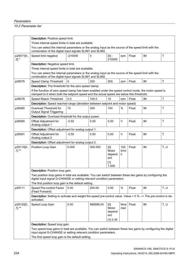
Parameters 10.2 Parameter list
SINAMICS V90, SIMOTICS S-1FL6 234 Operating Instructions, 04/2014, 6SL3298-0AV60-0BP0
Description: Positive speed limit. Three internal speed limits in total are available. You can select the internal parameters or the analog input as the source of the speed limit with the combination of the digital input signals SLIM1 and SLIM2.
p29071[0...2] *
Speed limit negative -210000 0 [0] -210000
rpm Float IM T
Description: Negative speed limit. Three internal speed limits in total are available. You can select the internal parameters or the analog input as the source of the speed limit with the combination of the digital input signals SLIM1 and SLIM2.
p29075 Speed Clamp Threshold 0 200 200 rpm Float IM T Description: The threshold for the zero speed clamp. If the function of zero speed clamp has been enabled under the speed control mode, the motor speed is clamped to 0 when both the setpoint speed and the actual speed are below this threshold.
p29078 Speed Reach Threshold 0.0 100.0 10 rpm Float IM T Description: Speed reached range (deviation between setpoint and motor speed)
p29080 Overload Threshold for Output Signal Triggering
10 300 100 % Float IM T
Description: Overload threshold for the output power. p29090 Offset Adjustment for
Analog output 1 -0.50 0.50 0.00 V Float IM T
Description: Offset adjustment for analog output 1. p29091 Offset Adjustment for
Analog output 2 -0.50 0.50 0.00 V Float IM T
Description: Offset adjustment for analog output 2. p29110[0...1] **
Position Loop Gain 0.000 300.000 [0] Motor dependent [1] 1.000
1000/min
Float IM T, U
Description: Position loop gain. Two position loop gains in total are available. You can switch between these two gains by configuring the digital input signal G-CHANGE or setting relevant condition parameters. The first position loop gain is the default setting.
p29111 Speed Pre-control Factor (Feed Forward)
0.00 200.00 0.00 % Float IM T, U
Description: Setting to activate and weight the speed pre-control value. Value = 0 % --> The pre-control is de-activated.
p29120[0...1] **
Speed Loop Gain 0.00 999999.00 [0] Motor dependent [1] 0.30
Nms/rad
Float IM T, U
Description: Speed loop gain. Two speed loop gains in total are available. You can switch between these two gains by configuring the digital input signal G-CHANGE or setting relevant condition parameters. The first speed loop gain is the default setting.

Parameters 10.2 Parameter list
SINAMICS V90, SIMOTICS S-1FL6 Operating Instructions, 04/2014, 6SL3298-0AV60-0BP0 235
p29121[0...1] *
Speed Loop Integral time 0.00 100000.00 [0] 15 [1] 20
ms Float IM T, U
Description: Speed loop integral time. Two speed loop integral time values in total are available. You can switch between these two time values by configuring the digital input signal G-CHANGE or setting relevant condition parameters. The first speed loop integral time is the default setting.
p29130
Gain Switching: Mode Selection
0 4 0 - I16 IM T
Description: Selects gain switching mode. • 0: Disabled • 1: Switch through DI-G-CHANG • 2: Position deviation as switch condition • 3: Pulse input frequency as switch condition • 4: Actual speed as switch condition Note: Only when the auto tuning function (p20021=0) is disabled can the gain switching function be used.
p29131 Gain Switching Condition: Pulse Deviation
0 2147483647
100 LU I32 IM T
Description: Triggers position deviation threshold for gain switching. If the gain switching function is enabled and this condition is selected: • Switch from the first group of control parameters to the second group when the position deviation is larger
than the threshold. • Switch from the second group of control parameters to the first group when the position deviation is
smaller than the threshold.
p29132 Gain Switching Condition: Position Setpoint Frequency
0 2147000064
100 1000 LU/min
Float IM T
Description: Triggers pulse input frequency (PTI) threshold or internal position speed (IPos) threshold for gain switching. If the gain switching function is enabled and this condition is selected: 1. PTI
– Switch from the first group of control parameters to the second group when the pulse train input pulse is higher than the threshold.
– Switch from the second group of control parameters to the first group when the pulse train input is lower than the threshold.
2. IPos – Switch from the first group of control parameters to the second group when the speed of fixed position
setpoint is larger than the threshold. – Switch from the second group of control parameters to the first group when the IPos is smaller than the
threshold.
p29133 Gain Switching Condition: Actual Speed
0 2147000064
100 rpm Float IM T
Description: Triggers speed threshold for gain switching. If the gain switching function is enabled and this condition is selected: • Switch from the first group of control parameters to the second group when the actual motor speed is
larger than the threshold. • Switch from the second group of control parameters to the first group when the actual motor speed is
smaller than the threshold.

Parameters 10.2 Parameter list
SINAMICS V90, SIMOTICS S-1FL6 236 Operating Instructions, 04/2014, 6SL3298-0AV60-0BP0
p29139 Gain switching Time Constant
8 1000 20 ms Float IM T
Description: Time constant for gain switching. Set this parameter to avoid frequent gain switches that reduces system reliability.
p29140 PI to P: Mode Selection 0 5 0 - U16 IM T Description: Selects a condition for the switch from PI control to P control under the speed loop. • 0: Disabled • 1: Torque is higher than a parameterizable setting value. • 2: Using the digital input signal (G-CHANGE). • 3: Speed is higher than a parameterizable setting value. • 4: Acceleration is higher than a parameterizable setting value. • 5: Pulse deviation is higher than a parameterizable setting value. Note: Only when the auto tuning function (p29021=0) and gain switching function are both disabled can the PI/P switching function be used.
p29141
PI to P Switching Condition: Torque
0 300 200 % Float IM T
Description: Triggers torque threshold for PI/P switching. If the PI/P switching function is enabled and this condition is selected: • Switch from the PI control to the P control when the actual torque is larger than the threshold. • Switch from the P control to the PI control when the actual torque is smaller than the threshold.
p29142 PI to P Switching Condition: Speed
0 210000 2000 rpm Float IM T
Description: Triggers speed threshold for PI/P switching. If the PI/P switching function is enabled and this condition is selected: • Switch from the PI control to the P control when the actual speed is larger than the threshold. • Switch from the P control to the PI control when the actual speed is smaller than the threshold.
p29143 PI to P Switching Condition: Acceleration
0 30000 20 rev/s²
Float IM T
Description: Triggers acceleration threshold for PI/P switching. If the PI/P switching function is enabled and this condition is selected: • Switch from the PI control to the P control when the actual acceleration is larger than the threshold. • Switch from the P control to the PI control when the actual acceleration is smaller than the threshold.
p29144 PI to P Switching Condition: Pulse Deviation
0 2147483647
30000 LU U32 IM T
Description: Triggers pulse deviation threshold for PI/P switching. If the PI/P switching function is enabled and this condition is selected: • Switch from the PI control to the P control when the actual pulse deviation is larger than the threshold. • Switch from the P control to the PI control when the actual pulse deviation is smaller than the threshold.

Parameters 10.2 Parameter list
SINAMICS V90, SIMOTICS S-1FL6 Operating Instructions, 04/2014, 6SL3298-0AV60-0BP0 237
p29240 Select Referencing Mode 0 4 1 - I16 RE T
Description: Selects referencing mode. • 0: Referencing with external signal REF • 1: Referencing with external reference cam (signal REF) • 2: Referencing with zero mark only • 3: Referencing with external reference cam (CCWL) and zero mark • 4: Referencing with external reference cam (CWL) and zero mark
p29241 Motion Mode 0 3 0 - U16 RE T Description: Moves mode set for IPos: • 0: means relative moving • 1: means abs moving • 2: POS Mod • 3: NEG Mod
p29242 CLR Pulse Mode 0 1 0 - U16 IM T Description: Indicates the mode for clear pulse. There are 4 bits for the setting, 3 is used and 1 is reserved. See below: bit 0: • 0: means automatically clear pulse when servo ON • 1: means clear pulse by the DI:CLR
p29245
Axis mode state 0 1 0 - U32 IM T Description: Linear/modulo mode • 0: Linear axis • 1: Modulo axis
p29246 * Axis mode no 1 4294967295
360000 - U32 IM T
Description: Modulo number, effective on modulo mode (P29245=1). p29247 * Mechanical gear: pulse
per revolution 1 214748364
7 10000 - U32 IM T
Description: LU per load revolution p29248 * Mechanical gear:
numerator 1 1048576 1 - U32 IM T
Description: (Load/Motor) Load revolutions p29249 * Mechanical gear:
denominator 1 1048576 1 - U32 IM T
Description: (Load/Motor) Motor revolutions p29250 PTI Absolute Position
Mode Enable 0 1 0 - U32 RE T
Description: Absolute Position Mode Enable. • =1 Enable Absolute Mode • =0 Disable Absolute Mode
p29300 Digital Input Forced Signals
0 63 0 - U32 IM T, U

Parameters 10.2 Parameter list
SINAMICS V90, SIMOTICS S-1FL6 238 Operating Instructions, 04/2014, 6SL3298-0AV60-0BP0
Description: Input signals are forced to be high. 6 bits in total. • bit 0: SON • bit 1: CWL • bit 2: CCWL • bit 3: TLIM1 • bit 4: SPD1 • bit 5: TSET If one or more bits are set to be high, the corresponding input signals are forced to be logical high signals. Note: The drive unit displays the value in hex format. To know the logic (high/low) assignment to each bit, you must convert the hex number to the binary number, for example, FF (hex) = 11111111 (bin).
p29301[0...3]
Digital Input 1 Assignment
0 28 1 - I16 IM T
Description: Defines the function of digital input signal DI1 (PTI mode) • SON 1 • RESET 2 • CWL 3 • CCWL 4 • G-CHANGE 5 • P-TRG 6 • CLR 7 • EGEAR1 8 • EGEAR2 9 • TLIMT1 10 • TLIMT2 11 • CWLE 12 • CCWLE 13 • ZSCLAMP 14 • SPD1 15 • SPD2 16 • SPD3 17 • TSET 18 • SLIMT1 19 • SLIMT2 20 • POS1 21 • POS2 22 • POS3 23 • REF 24 • SREF 25 • STEPF 26 • STEPB 27 • STEPH 28
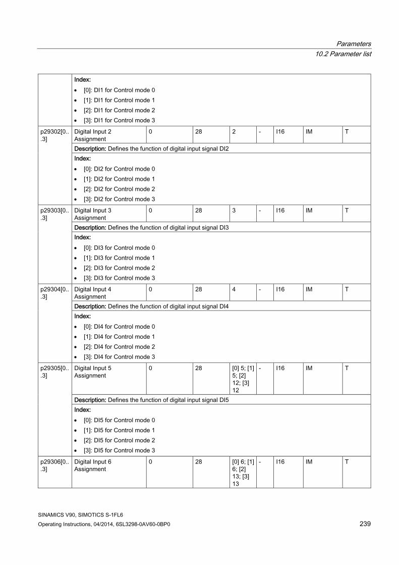
Parameters 10.2 Parameter list
SINAMICS V90, SIMOTICS S-1FL6 Operating Instructions, 04/2014, 6SL3298-0AV60-0BP0 239
Index: • [0]: DI1 for Control mode 0 • [1]: DI1 for Control mode 1 • [2]: DI1 for Control mode 2 • [3]: DI1 for Control mode 3
p29302[0...3]
Digital Input 2 Assignment
0 28 2 - I16 IM T
Description: Defines the function of digital input signal DI2 Index: • [0]: DI2 for Control mode 0 • [1]: DI2 for Control mode 1 • [2]: DI2 for Control mode 2 • [3]: DI2 for Control mode 3
p29303[0...3]
Digital Input 3 Assignment
0 28 3 - I16 IM T
Description: Defines the function of digital input signal DI3 Index: • [0]: DI3 for Control mode 0 • [1]: DI3 for Control mode 1 • [2]: DI3 for Control mode 2 • [3]: DI3 for Control mode 3
p29304[0...3]
Digital Input 4 Assignment
0 28 4 - I16 IM T
Description: Defines the function of digital input signal DI4 Index: • [0]: DI4 for Control mode 0 • [1]: DI4 for Control mode 1 • [2]: DI4 for Control mode 2 • [3]: DI4 for Control mode 3
p29305[0...3]
Digital Input 5 Assignment
0 28 [0] 5; [1] 5; [2] 12; [3] 12
- I16 IM T
Description: Defines the function of digital input signal DI5 Index: • [0]: DI5 for Control mode 0 • [1]: DI5 for Control mode 1 • [2]: DI5 for Control mode 2 • [3]: DI5 for Control mode 3
p29306[0...3]
Digital Input 6 Assignment
0 28 [0] 6; [1] 6; [2] 13; [3] 13
- I16 IM T

Parameters 10.2 Parameter list
SINAMICS V90, SIMOTICS S-1FL6 240 Operating Instructions, 04/2014, 6SL3298-0AV60-0BP0
Description: Defines the function of digital input signal DI6 Index: • [0]: DI6 for Control mode 0 • [1]: DI6 for Control mode 1 • [2]: DI6 for Control mode 2 • [3]: DI6 for Control mode 3
p29307[0...3]
Digital Input 7 Assignment
0 28 [0] 7; [1] 21; [2] 15; [3] 18
- I16 IM T
Description: Defines the function of digital input signal DI7 Index: • [0]: DI7 for Control mode 0 • [1]: DI7 for Control mode 1 • [2]: DI7 for Control mode 2 • [3]: DI7 for Control mode 3
p29308[0...3]
Digital Input 8 Assignment
0 28 [0] 10; [1] 22; [2] 16; [3] 19
- I16 IM T
Description: Defines the function of digital input signal DI8 Index: • [0]: DI8 for Control mode 0 • [1]: DI8 for Control mode 1 • [2]: DI8 for Control mode 2 • [3]: DI8 for Control mode 3
p29330 Digital Output 1 Assignment
1 13 1 - U16 IM T
Description: Defines the function of digital output signal DO1 • 1: RDY • 2: ALM • 3: INP • 4: ZSP • 5: SPDR • 6: TLR • 7: SPLR • 8: MBR • 9: OLL • 10: WRN1 • 11: WRN2 • 12: REFOK • 13: CM_STA

Parameters 10.2 Parameter list
SINAMICS V90, SIMOTICS S-1FL6 Operating Instructions, 04/2014, 6SL3298-0AV60-0BP0 241
p29331 Digital Output 2 Assignment
1 13 2 - U16 IM T
Description: Defines the function of digital output signal DO2 p29332 Digital Output 3
Assignment 1 13 3 - U16 IM T
Description: Defines the function of digital output signal DO3 p29333 Digital Output 4
Assignment 1 13 5 - U16 IM T
Description: Defines the function of digital output signal DO4 p29334 Digital Output 5
Assignment 1 13 6 - U16 IM T
Description: Defines the function of digital output signal DO5 p29335 Digital Output 6
Assignment 1 13 8 - U16 IM T
Description: Defines the function of digital output signal DO6 p29340 Warning 1 Assigned for
Digital Output 1 6 1 - U16 IM T
Description: Defines conditions for WRN1. • 1: Motor overload protection warning: 85% of overload threshold has been reached. • 2: Holding brake power overload warning: 85% of overload threshold has been reached. • 3: Fan warning: fan has stopped for more than 1 s. • 4: Encoder warning • 5: Motor overtemperature warning: 85% of overtemperature threshold has been reached. • 6: Capacitor service life warning: The capacitor has reached its expiry, so replace it.
p29341
Warning 2 Assigned for Digital Output
1 6 2 - U16 IM T
Description: Defines conditions for WRN2. • 1: Motor overload protection warning: 85% of overload threshold has been reached. • 2: Holding brake power overload warning: 85% of overload threshold has been reached. • 3: Fan warning: life time of fan expired (40000 hours), replacement of fan needed. • 4: Encoder warning • 5: Motor overtemperature warning: 85% of overtemperature threshold has been reached. • 6: Capacitor service life warning: The capacitor has reached its expiry, so replace it.

Parameters 10.2 Parameter list
SINAMICS V90, SIMOTICS S-1FL6 242 Operating Instructions, 04/2014, 6SL3298-0AV60-0BP0
p29350 Select sources for analog output 1
0 12 0 - U16 IM T
Description: Selects signal source for analog output 1. • 0: Actual speed (reference p29060) • 1: Actual torque (reference 3 × r0333) • 2: Speed setpoint (reference p29060) • 3: Torque setpoint (reference 3 × r0333) • 4: DC bus voltage (reference 1000 V) • 5: Pulse input frequency (reference 1k) • 6: Pulse input frequency (reference 10k) • 7: Pulse input frequency (reference 100k) • 8: Pulse input frequency (reference 1000k) • 9: Remaining number of pulses (reference 1k) • 10: Remaining number of pulses (reference 10k) • 11: Remaining number of pulses (reference 100k) • 12: Remaining number of pulses (reference 1000k)
p29351 Select Signal Source for Analog 2
0 12 1 - U16 IM T
Description: Selects signals for analog output 2. • 0: Actual speed (reference p29060) • 1: Actual torque (reference 3 × r0333) • 2: Speed setpoint (reference p29060) • 3: Torque setpoint (reference 3 × r0333) • 4: DC bus voltage (reference 1000 V) • 5: Pulse input frequency (reference 1k) • 6: Pulse input frequency (reference 10k) • 7: Pulse input frequency (reference 100k) • 8: Pulse input frequency (reference 1000k) • 9: Remaining number of pulses (reference 1k) • 10: Remaining number of pulses (reference 10k) • 11: Remaining number of pulses (reference 100k) • 12: Remaining number of pulses (reference 1000k)
* Note that the parameter value may be changed after commissioning. Make sure you back up the parameters first as required if you desire to replace the motor.
** Note that the parameter default values are motor dependent. They may have different default values when different motor connected.

Parameters 10.2 Parameter list
SINAMICS V90, SIMOTICS S-1FL6 Operating Instructions, 04/2014, 6SL3298-0AV60-0BP0 243
Read-only parameters Par. No. Name Unit Data type r0020 Speed setpoint smoothed rpm Float
Description: Displays the currently smoothed speed setpoint at the input of the speed controller or U/f characteristic (after the interpolator). Note: Smoothing time constant = 100 ms The signal is not suitable as a process quantity and may only be used as a display quantity. The speed setpoint is available smoothed (r0020) and unsmoothed.
r0021 Actual speed smoothed rpm Float Description: Displays the smoothed actual value of the motor speed. Note: Smoothing time constant = 100 ms The signal is not suitable as a process quantity and may only be used as a display quantity. The speed actual value is available smoothed (r0021) and unsmoothed.
r0026 DC link voltage smoothed V Float Description: Displays the smoothed actual value of the DC link voltage. Notice: When measuring a DC link voltage < 200 V, for the Power Module (e.g. PM340) a valid measured value is not supplied. In this case, when an external 24 V power supply is connected, a value of approx. 24 V is displayed in the display parameter. Note: Smoothing time constant = 100 ms The signal is not suitable as a process quantity and may only be used as a display quantity. The DC link voltage is available smoothed (r0026) and unsmoothed.
r0027 Absolute actual current smoothed Arms Float Description: Displays the smoothed absolute actual current value. Notice: This smoothed signal is not suitable for diagnostics or evaluation of dynamic operations. In this case, the unsmoothed value should be used. Note: Smoothing time constant = 100 ms The signal is not suitable as a process quantity and may only be used as a display quantity. The absolute current actual value is available smoothed (r0027) and unsmoothed.
r0029 Current actual value field-generating smoothed Arms Float Description: Displays the smoothed field-generating actual current. Note: Smoothing time constant = 100 ms The signal is not suitable as a process quantity and may only be used as a display quantity. The field-generating current actual value is available smoothed (r0029) and unsmoothed.
r0030 Current actual value torque-generating smoothed Arms Float Description: Displays the smoothed torque-generating actual current. Note: Smoothing time constant = 100 ms The signal is not suitable as a process quantity and may only be used as a display quantity. The torque-generating current actual value is available smoothed.
r0031 Actual torque smoothed Nm Float Description: Displays the smoothed torque actual value. Note: Smoothing time constant = 100 ms The signal is not suitable as a process quantity and may only be used as a display quantity. The torque actual value is available smoothed (r0031) and unsmoothed.

Parameters 10.2 Parameter list
SINAMICS V90, SIMOTICS S-1FL6 244 Operating Instructions, 04/2014, 6SL3298-0AV60-0BP0
Par. No. Name Unit Data type r0033 Torque utilization smoothed % Float
Description: Displays the smoothed torque utilization as a percentage. The torque utilization is obtained from the required smoothed torque in reference to the torque limit, scaled using p2196. Note: Smoothing time constant = 100 ms The signal is not suitable as a process quantity and may only be used as a display quantity. The torque utilization is available smoothed (r0033) and unsmoothed. For M_set total (r0079) > M_max offset, the following applies: • demanded torque = M_set total - M_max offset • actual torque limit = M_max upper effective - M_max offset For M_set total (r0079) <= M_max offset (p1532), the following applies: • demanded torque = M_max offset - M_set total • actual torque limit = M_max offset - M_max lower effective For the actual torque limit = 0, the following applies: r0033 = 100 % For the actual torque limit < 0, the following applies: r0033 = 0 %
r0037[0...19] Power unit temperatures °C Float Description: Displays the temperatures in the power unit. Index: • [0]: Inverter maximum value • [1]: Depletion layer maximum value • [2]: Rectifier maximum value • [3]: Air intake • [4]: Interior of power unit • [5]: Inverter 1 • [6]: Inverter 2 • [7]: Inverter 3 • [8]: Inverter 4 • [9]: Inverter 5 • [10]: Inverter 6 • [11]: Rectifier 1 • [12]: Rectifier 2 • [13]: Depletion layer 1 • [14]: Depletion layer 2 • [15]: Depletion layer 3 • [16]: Depletion layer 4 • [17]: Depletion layer 5 • [18]: Depletion layer 6 • [19]: Cooling unit liquid intake
Dependency: Refer to A01009 Notice: Only for internal Siemens troubleshooting.
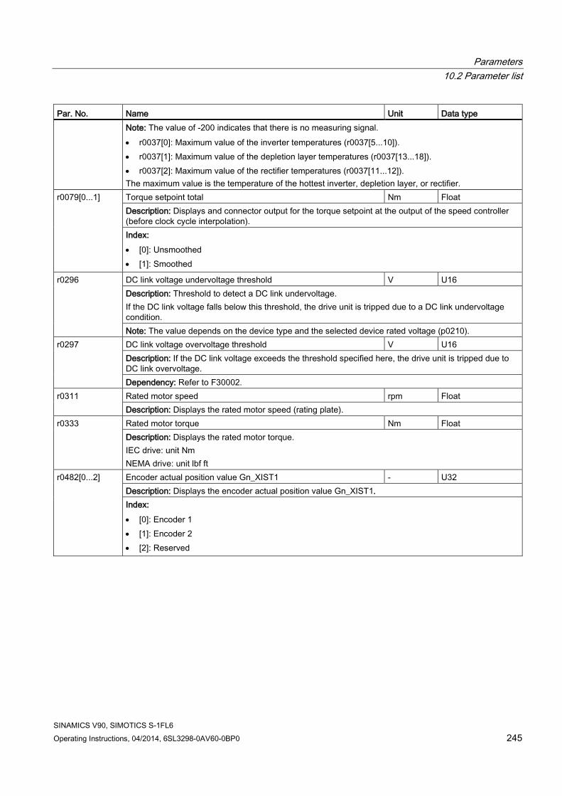
Parameters 10.2 Parameter list
SINAMICS V90, SIMOTICS S-1FL6 Operating Instructions, 04/2014, 6SL3298-0AV60-0BP0 245
Par. No. Name Unit Data type Note: The value of -200 indicates that there is no measuring signal. • r0037[0]: Maximum value of the inverter temperatures (r0037[5...10]). • r0037[1]: Maximum value of the depletion layer temperatures (r0037[13...18]). • r0037[2]: Maximum value of the rectifier temperatures (r0037[11...12]). The maximum value is the temperature of the hottest inverter, depletion layer, or rectifier.
r0079[0...1] Torque setpoint total Nm Float Description: Displays and connector output for the torque setpoint at the output of the speed controller (before clock cycle interpolation). Index: • [0]: Unsmoothed • [1]: Smoothed
r0296 DC link voltage undervoltage threshold V U16 Description: Threshold to detect a DC link undervoltage. If the DC link voltage falls below this threshold, the drive unit is tripped due to a DC link undervoltage condition. Note: The value depends on the device type and the selected device rated voltage (p0210).
r0297 DC link voltage overvoltage threshold V U16 Description: If the DC link voltage exceeds the threshold specified here, the drive unit is tripped due to DC link overvoltage. Dependency: Refer to F30002.
r0311 Rated motor speed rpm Float Description: Displays the rated motor speed (rating plate).
r0333
Rated motor torque Nm Float Description: Displays the rated motor torque. IEC drive: unit Nm NEMA drive: unit lbf ft
r0482[0...2] Encoder actual position value Gn_XIST1 - U32 Description: Displays the encoder actual position value Gn_XIST1. Index: • [0]: Encoder 1 • [1]: Encoder 2 • [2]: Reserved

Parameters 10.2 Parameter list
SINAMICS V90, SIMOTICS S-1FL6 246 Operating Instructions, 04/2014, 6SL3298-0AV60-0BP0
Par. No. Name Unit Data type Note: • In this value, the measuring gear is only taken into account when the position tracking is activated. • The update time for the position control (EPOS) corresponds to the position controller clock cycle. • The update time in isochronous operation corresponds to the bus cycle time. • The update time in isochronous operation and with position control (EPOS) corresponds to the
position controller clock cycle. • The update time in non-isochronous operation or without position control (EPOS) comprises the
following: – Update time = 4 * least common multiple (LCM) of all current controller clock cycles in the drive
group (infeed + drives). The minimum update time is 1 ms. – Example 1: infeed, servo
Update time = 4 * LCM(250 μs, 125 μs) = 4 * 250 μs = 1 ms – Example 2: infeed, servo, vector
Update time = 4 * LCM(250 μs, 125 μs, 500 μs) = 4 * 500 μs = 2 ms
r0632
Motor temperature model, stator winding temperature
°C Float
Description: Displays the stator winding temperature of the motor temperature model. r0722 CU digital inputs status - U32
Description: Displays the status of the digital inputs. Note: DI: Digital Input DI/DO: Bidirectional Digital Input/Output The drive unit displays the value in hex format. You can convert the hex number to the binary number, for example, FF (hex) = 11111111 (bin).
r0747 CU digital outputs status - U32 Description: Displays the status of digital outputs. Note: DI/DO: Bidirectional Digital Input/Output The drive unit displays the value in hex format. You can convert the hex number to the binary number, for example, FF (hex) = 11111111 (bin).
r2521[0...3] LR position actual value LU I32 Description: Displays the actual position actual value determined by the position actual value preprocessing. Index: • [0]: Cl-loop pos ctrl • [1]: Encoder 1 • [2]: Encoder 2 • [3]: Reserved
r2563
LR following error dynamic model LU I32 Description: Displays the dynamic following error. This value is the deviation, corrected by the velocity-dependent component, between the position setpoint and the position actual value.
r2665 EPOS position setpoint LU I32 Description: Displays the actual absolute position setpoint.

Parameters 10.2 Parameter list
SINAMICS V90, SIMOTICS S-1FL6 Operating Instructions, 04/2014, 6SL3298-0AV60-0BP0 247
Par. No. Name Unit Data type r29015
PTI: Pulse input frequency Hz Float Description: Displays the PTI input pulse frequency.
r29018 OA version - Float Description: Firmware version
r29400
Internal Control Signal Status Indicating - U32 Description: Control signal status identifiers bit00 SON bit01 RESET bit02 CWL bit03 CCWL bit04 G-CHANGE bit05 P-TRG bit06 CLR bit07 EGEAR1 bit08 EGEAR2 bit09 TLIMT1 bit10 TLIMT2 bit11 CWLE bit12 CCWLE bit13 ZSCLAMP bit14 SPD1 bit15 SPD2 bit16 SPD3 bit17 TSET bit18 SLIMT1 bit19 SLIMT2 bit20 POS1 bit21 POS2 bit22 POS3 bit23 REF bit24 SREF bit25 STEPF bit26 STEPB bit27 STEPH bit28 EMGS bit29 C-MODE
r29942
DO signals status indicating - U32 Description: Indicates the status of DO signals. • bit 0: RD • bit 1: FAULT • bit 2: INP • bit 3: ZSP • bit 4: SPDR • bit 5: TLR • bit 6: SPLR • bit 7: MBR • bit 8: OLL • bit 9: WARNING1 • bit 10: WARNING2 • bit 11: REFOK • bit 12: MODE_SELECTED
r29979 PStatus - U32 Description: Displays the status of position loop. • bit 0 - bit 1: actual EGear index

Parameters 10.2 Parameter list
SINAMICS V90, SIMOTICS S-1FL6 248 Operating Instructions, 04/2014, 6SL3298-0AV60-0BP0

SINAMICS V90, SIMOTICS S-1FL6 Operating Instructions, 04/2014, 6SL3298-0AV60-0BP0 249
Diagnostics 11 11.1 Overview
Differences between faults and alarms The differences between faults and alarms are shown as follows:
Type BOP display (example) Status indicator Reaction Acknowledgement
RDY COM Fault
Single fault Slow
flashing in red
- • NONE: no reaction • OFF1: servo motor
ramps down • OFF2: servo motor
coasts down • OFF3: servo motor
stops quickly (emergency stop)
• ENOCDER: Encoder fault causes OFF2.
• POWER ON: re-power on the servo drive to clear a fault after eliminating its cause.
• IMMEDIATELY: the fault disappears immediately after eliminating its cause.
• PULSE INHIBIT: The fault can only be acknowledged with a pulse inhibit. The same options are available for acknowledging as described under acknowledgment with IMMEDIATELY.
The first fault in the case of multiple faults
Non-first fault in the case of multiple faults
Alarm
Single alarm Slow flashing in red
- • NONE: no reaction Self-acknowledgement
The first alarm in the case of multiple alarms
Non-first alarm in the case of multiple alarms

Diagnostics 11.1 Overview
SINAMICS V90, SIMOTICS S-1FL6 250 Operating Instructions, 04/2014, 6SL3298-0AV60-0BP0
NOTICE
Faults have higher display priority than alarms
In the case that both faults and alarms occur, only faults are displayed until they have been acknowledged.
BOP operations for faults and alarms To view faults or alarms, proceed as follows:
● Faults
Figure 11-1 Viewing faults
● Alarms
Figure 11-2 Viewing alarms
To exit from fault or alarm display, proceed as follows:
● Faults
Figure 11-3 Exiting from fault display

Diagnostics 11.1 Overview
SINAMICS V90, SIMOTICS S-1FL6 Operating Instructions, 04/2014, 6SL3298-0AV60-0BP0 251
● Alarms
Figure 11-4 Exiting from alarm display
To acknowledge faults, proceed as follows:
Figure 11-5 Acknowledging faults
Note • If you do not eliminate the cause(s) of the fault, it can appear again after no button
operation for five seconds. Make sure that you have eliminated the cause(s) of the fault. • You can acknowledge faults using RESET signal. For details of the signal, refer to DIs
(Page 62). • You can acknowledge faults on the SINAMICS V-ASSISTANT. For details, refer to
SINAMICS V-ASSISTANT Online Help.
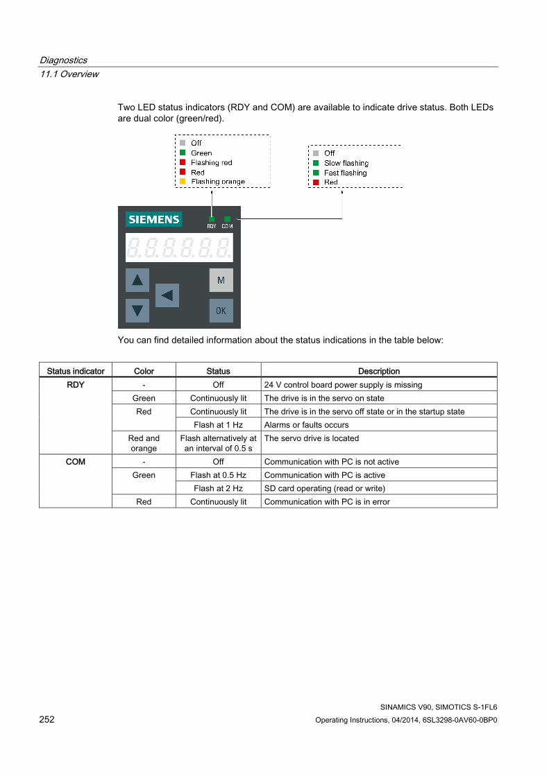
Diagnostics 11.1 Overview
SINAMICS V90, SIMOTICS S-1FL6 252 Operating Instructions, 04/2014, 6SL3298-0AV60-0BP0
Two LED status indicators (RDY and COM) are available to indicate drive status. Both LEDs are dual color (green/red).
You can find detailed information about the status indications in the table below:
Status indicator Color Status Description
RDY - Off 24 V control board power supply is missing Green Continuously lit The drive is in the servo on state Red Continuously lit The drive is in the servo off state or in the startup state
Flash at 1 Hz Alarms or faults occurs Red and orange
Flash alternatively at an interval of 0.5 s
The servo drive is located
COM - Off Communication with PC is not active Green Flash at 0.5 Hz Communication with PC is active
Flash at 2 Hz SD card operating (read or write) Red Continuously lit Communication with PC is in error

Diagnostics 11.2 List of faults and alarms
SINAMICS V90, SIMOTICS S-1FL6 Operating Instructions, 04/2014, 6SL3298-0AV60-0BP0 253
11.2 List of faults and alarms
Fault list Fault Cause Remedy F1000: Internal software error Reaction: OFF2 Acknowledgement: POWER ON
An internal software error has occurred. • Evaluate fault buffer. • Carry out a POWER ON (power off/on) for
all components. • Upgrade firmware to later version. • Contact the Hotline. • Replace the Control Unit.
F1001: FloatingPoint exception Reaction: OFF2 Acknowledgement: POWER ON
An exception occurred during an operation with the FloatingPoint data type.
• Carry out a POWER ON (power off/on) for all components.
• Upgrade firmware to the latest version. • Contact the Hotline.
F1002: Internal software error Reaction: OFF2 Acknowledgement: IMMEDIATELY
An internal software error has occurred. • Carry out a POWER ON (power off/on) for all components.
• Upgrade firmware to the latest version. • Contact the Hotline.
F1003: Acknowledgement delay when accessing the memory Reaction: OFF2 Acknowledgement: IMMEDIATELY
A memory area was accessed that does not return a "READY".
• Carry out a POWER ON (power off/on) for all components.
• Contact the Hotline.
F1015: Internal software error Reaction: OFF2 Acknowledgement: POWER ON
An internal software error has occurred. • Carry out a POWER ON (power off/on) for all components.
• Upgrade firmware to the latest version. • Contact the Hotline.

Diagnostics 11.2 List of faults and alarms
SINAMICS V90, SIMOTICS S-1FL6 254 Operating Instructions, 04/2014, 6SL3298-0AV60-0BP0
Fault Cause Remedy F1018: Booting has been interrupted several times Reaction: NONE Acknowledgement: POWER ON
Module booting was interrupted several times. As a consequence, the module boots with the factory setting. Possible reasons for booting being interrupted: • Power supply interrupted. • CPU crashed. • Parameterization invalid. After this fault is output, then the module is booted with the factory settings.
• Carry out a POWER ON (power off/on). After switching on, the module reboots from the valid parameterization (if available).
• Restore the valid parameterization Examples: • Carry out a first commissioning, save,
carry out a POWER ON (switch-off/switch-on).
• Load another valid parameter backup (e.g. from the memory card), save, carry out a POWER ON (switch-off/switch-on).
Note: If the fault situation is repeated, then this fault is again output after several interrupted boots.
F1030: Sign-of-life failure for master control Reaction: OFF3 Acknowledgement: IMMEDIATELY
For active PC master control, no sign-of-life was received within the monitoring time.
Contact the Hotline.
F1611: SI CU: Defect detected Reaction: OFF2 Acknowledgement: IMMEDIATELY
The drive-integrated "Safety Integrated" (SI) function on the Control Unit (CU) has detected an error and initiated an STO
• Carry out a POWER ON (power off/on) for all components.
• Upgrade software. • Replace the Control Unit.
F7011: Motor overtemperature Reaction: OFF2 Acknowledgement: IMMEDIATELY
• Motor overloaded • Motor surrounding temperature too
high • Wire breakage or sensor not connected • Motor temperature model incorrectly
parameterized
• Reduce the motor load. • Check the surrounding temperature and
the motor ventilation. • Check the wiring and the connection. • Check the motor temperature model
parameters.
F7085: Open-loop/closed-loop control parameters changed Reaction: NONE Acknowledgement: IMMEDIATELY
Open-loop/closed-loop control parameters have had to be changed for the following reasons: • As a result of other parameters, they
have exceeded the dynamic limits. • They cannot be used due to the fact
that the hardware detected not having certain features.
It is not necessary to change the parameters as they have already been correctly limited.
F7403: Lower DC link voltage threshold reached Reaction: OFF1 Acknowledgement: IMMEDIATELY
The DC link voltage monitoring is active and the lower DC link voltage threshold was reached in the "Operation" state.
• Check the line supply voltage. • Check the infeed. • Reduce the lower DC link threshold. • Switch out (disable) the DC link voltage
monitoring.

Diagnostics 11.2 List of faults and alarms
SINAMICS V90, SIMOTICS S-1FL6 Operating Instructions, 04/2014, 6SL3298-0AV60-0BP0 255
Fault Cause Remedy F7404: Upper DC link voltage threshold reached Reaction: OFF2 Acknowledgement: IMMEDIATELY
The DC link voltage monitoring is active and the upper DC link voltage threshold was reached in the "Operation" state.
• Check the line supply voltage. • Check the infeed module or the brake
module. • Increase the upper DC link voltage
threshold. • Switch out (disable) the DC link voltage
monitoring.
F7410: Current controller output limited Reaction: OFF2 Acknowledgement: IMMEDIATELY
The condition "I_act = 0 and Uq_set_1 longer than 16 ms at its limit" is present and can be caused by the following: • Motor not connected or motor contactor
open. • No DC link voltage present. • Motor Module defective.
• Connect the motor or check the motor contactor.
• Check the DC link voltage. • Check the Motor Module.
F7412: Commutation angle incorrect (motor model) Reaction: ENCODER Acknowledgement: IMMEDIATELY
An incorrect commutation angle was detected that can result in a positive coupling in the speed controller. Possible causes: • The motor encoder is incorrectly
adjusted with respect to the magnet position.
• The motor encoder is damaged. • Data to calculate the motor model has
been incorrectly set. • Pole position identification might have
calculated an incorrect value when activated.
• The motor encoder speed signal is faulted.
• The control loop is instable due to incorrect parameterization.
• If the encoder mounting was changed, re-adjust the encoder.
• Replace the defective motor encoder. • Correctly set the motor stator resistance,
cable resistance and motor-stator leakage inductance. Calculate the cable resistance from the cross-section and length, check the inductance and stator resistance using the motor data sheet, measure the stator resistance, e.g. using a multimeter - and if required, again identify the values using the stationary motor data identification.
• With pole position identification activated, check the procedure for pole position identification and force a new pole position identification procedure by means of de-selection followed by selection.
F7430: Changeover to open-loop torque controlled operation not possible Reaction: OFF2 Acknowledgement: POWER ON
For encoderless operation, the converter cannot change over to closed-loop torque-controlled operation.
• Do not attempt to change over to closed-loop torque-controlled operation.
• Check the encoder cable connection.
F7431: Changeover to encoderless operation not possible Reaction: OFF2 Acknowledgement: POWER ON
For closed-loop torque control, the converter cannot change over to encoderless operation.
• Do not attempt to change over to encoderless operation.
• Check the encoder cable connection.

Diagnostics 11.2 List of faults and alarms
SINAMICS V90, SIMOTICS S-1FL6 256 Operating Instructions, 04/2014, 6SL3298-0AV60-0BP0
Fault Cause Remedy F7442: LR: Multiturn does not match the modulo range Reaction: OFF1 (OFF2, OFF3) Acknowledgement: IMMEDIATELY
The ratio between the multiturn resolution and the modulo range (p29246) is not an integer number. This results in the adjustment being set back, as the position actual value cannot be reproduced after power-off/power-on.
Make the ration between the multiturn resolution and the modulo range an integer number. The ratio v is calculated as follows: v = (4096 * p29247 * p29248) / (p29249 * p29246)
F7443: Reference point coordinate not in the permissible range Reaction: OFF1 (OFF2, OFF3) Acknowledgement: IMMEDIATELY
The reference point coordinate received when adjusting the encoder via connector input p2599 lies outside the half of the encoder range and cannot be set as actual axis position.
Set the reference point coordinate to a lower value than specified in the fault value. See also: p2599 (EPOS reference point coordinate value. For a motor with an absolute encoder, the maximum permissible encoder range is calculated by the formula (4096xp29247)/2.
F7450: Standstill monitoring has responded Reaction: OFF1 Acknowledgement: IMMEDIATELY
After the standstill monitoring time expired, the drive left the standstill window. • Position loop gain too low. • Position loop gain too high
(instability/oscillation). • Mechanical overload. • Connecting cable, motor/drive
converter incorrect (phase missing, interchange).
Check the causes and resolve.
F7452: Following error too high Reaction: OFF1 Acknowledgement: IMMEDIATELY
The difference between the position setpoint position actual value (following error dynamic model) is greater than the tolerance. • The drive torque or accelerating
capacity exceeded. • Position measuring system fault. • Position control sense incorrect. • Mechanical system locked. • Excessively high traversing velocity or
excessively high position reference value (setpoint) differences.
Check the causes and resolve.
F7453: Position actual value preprocessing error Reaction: OFF1 Acknowledgement: IMMEDIATELY
An error has occurred during the position actual value preprocessing.
Check the encoder for the position actual value preprocessing.
F7458: EPOS: Reference cam not found Reaction: OFF1 (OFF2, OFF3) Acknowledgement: IMMEDIATELY
After starting the search for reference, the axis moved through the maximum permissible distance to search for the reference cam without actually finding the reference cam.
• Check the "reference cam" input. • Check the maximum permissible distance
to the reference cam (p2606). See also: p2606 (EPOS search for reference cam maximum distance)
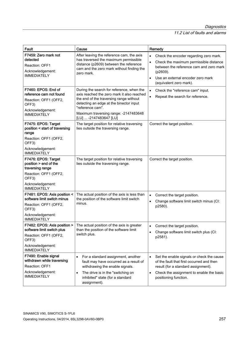
Diagnostics 11.2 List of faults and alarms
SINAMICS V90, SIMOTICS S-1FL6 Operating Instructions, 04/2014, 6SL3298-0AV60-0BP0 257
Fault Cause Remedy F7459: Zero mark not detected Reaction: OFF1 Acknowledgement: IMMEDIATELY
After leaving the reference cam, the axis has traversed the maximum permissible distance (p2609) between the reference cam and the zero mark without finding the zero mark.
• Check the encoder regarding zero mark. • Check the maximum permissible distance
between the reference cam and zero mark (p2609).
• Use an external encoder zero mark (equivalent zero mark).
F7460: EPOS: End of reference cam not found Reaction: OFF1 (OFF2, OFF3) Acknowledgement: IMMEDIATELY
During the search for reference, when the axis reached the zero mark it also reached the end of the traversing range without detecting an edge at the binector input "reference cam". Maximum traversing range: -2147483648 [LU] ... -2147483647 [LU]
• Check the "reference cam" input. • Repeat the search for reference.
F7475: EPOS: Target position < start of traversing range Reaction: OFF1 (OFF2, OFF3) Acknowledgement: IMMEDIATELY
The target position for relative traversing lies outside the traversing range.
Correct the target position.
F7476: EPOS: Target position > end of the traversing range Reaction: OFF1 (OFF2, OFF3) Acknowledgement: IMMEDIATELY
The target position for relative traversing lies outside the traversing range.
Correct the target position.
F7481: EPOS: Axis position < software limit switch minus Reaction: OFF1 (OFF2, OFF3) Acknowledgement: IMMEDIATELY
The actual position of the axis is less than the position of the software limit switch minus.
• Correct the target position. • Change software limit switch minus (CI:
p2580).
F7482: EPOS: Axis position > software limit switch plus Reaction: OFF1 (OFF2, OFF3) Acknowledgement: IMMEDIATELY
The actual position of the axis is greater than the position of the software limit switch plus.
• Correct the target position. • Change software limit switch plus (CI:
p2581).
F7490: Enable signal withdrawn while traversing Reaction: OFF1 Acknowledgement: IMMEDIATELY
• For a standard assignment, another fault may have occurred as a result of withdrawing the enable signals.
• The drive is in the "switching on inhibited" state (for a standard assignment).
• Set the enable signals or check the cause of the fault that first occurred and then result (for a standard assignment).
• Check the assignment to enable the basic positioning function.

Diagnostics 11.2 List of faults and alarms
SINAMICS V90, SIMOTICS S-1FL6 258 Operating Instructions, 04/2014, 6SL3298-0AV60-0BP0
Fault Cause Remedy F7491: STOP cam minus reached Reaction: OFF3 Acknowledgement: IMMEDIATELY
The STOP cam minus was reached. For a positive traversing direction, the STOP cam minus was reached, i.e. the wiring of the STOP cam is incorrect.
• Leave the STOP cam minus in the positive traversing direction and return the axis to the valid traversing range.
• Check the wiring of the STOP cam.
F7492: STOP cam plus reached Reaction: OFF3 Acknowledgement: IMMEDIATELY
The STOP cam plus was reached. For a negative traversing direction, the STOP cam plus was reached, i.e. the wiring of the STOP cam is incorrect.
• Leave the STOP cam plus in the negative traversing direction and return the axis to the valid traversing range.
• Check the wiring of the STOP cam.
F7493: LR: Overflow of the value range for position actual value Reaction: OFF1 (OFF2, OFF3) Acknowledgement: IMMEDIATELY
The value range (-2147483648 ... 2147483647) for the position actual value representation was exceeded. When the overflow occurs, the "referenced" or "adjustment absolute measuring system" status is reset. • The position actual value (r2521) has
exceeded the value range. • The encoder position actual value has • exceeded the value range. • The maximum encoder value times the
factor to convert the absolute position from increments to length units (LU) has exceeded the value range for displaying the position actual value.
If required, reduce the traversing range or position resolution p29247. Note for case = 3: If the value for the maximum possible absolute position (LU) is greater than 4294967296, then it is not possible to make an adjustment due to an overflow. For rotary encoders, the maximum possible absolute position (LU) is calculated as follows: Motor encoder without position tracking: • IPOS: p29247 * p29248 * 4096 / p29249
for multiturn encoders • PTI: 1048576 * p29012[X] * 4096
/ p29013 for multiturn encoders
F7599: Encoder 1: Adjustment not possible Reaction: OFF1 (NONE, OFF2, OFF3) Acknowledgement: IMMEDIATELY
The maximum encoder value times the factor to convert the absolute position from increments to length units (LU) has exceeded the value range (-2147483648 ... 2147483647) for displaying the position actual value.
If the value for the maximum possible absolute position (LU) is greater than 4294967296, then it is not possible to make an adjustment due to an overflow. For rotary encoders, the maximum possible absolute position (LU) is calculated as follows: Motor encoder without position tracking: • IPOS: p29247 * p29248 * 4096 / p29249
for multiturn encoders • PTI: 1048576 * p29012[X] * 4096
/ p29013 for multiturn encoders

Diagnostics 11.2 List of faults and alarms
SINAMICS V90, SIMOTICS S-1FL6 Operating Instructions, 04/2014, 6SL3298-0AV60-0BP0 259
Fault Cause Remedy F7801: Motor overcurrent Reaction: OFF2 Acknowledgement: IMMEDIATELY
The permissible motor limit current was exceeded. • Effective current limit set too low. • Current controller not correctly set. • Motor was braked with an excessively
high stall torque correction factor. • Up ramp was set too short or the load
is too high. • Short-circuit in the motor cable or
ground fault. • Motor current does not match the
current of Motor Module.
• Reduce the stall torque correction factor. • Increase the up ramp or reduce the load. • Check the motor and motor cables for
short-circuit and ground fault. • Check the Motor Module and motor
combination.
F7802: Infeed or power unit not ready Reaction: OFF2 Acknowledgement: IMMEDIATELY
After an internal power-on command, the infeed or drive does not signal ready because of one of the following reasons: • Monitoring time is too short. • DC link voltage is not present. • Associated infeed or drive of the
signaling component is defective.
• Ensure that there is a DC link voltage. Check the DC link busbar. Enable the infeed.
• Replace the associated infeed or drive of the signaling component.
F7815: Power unit has been changed Reaction: NONE Acknowledgement: IMMEDIATELY
The code number of the actual power unit does not match the saved number.
Connect the original power unit and power up the Control Unit again (POWER ON).
F7900: Motor blocked/speed controller at its limit Reaction: OFF2 Acknowledgement: IMMEDIATELY
The servo motor has been operating at the torque limit longer than 1s and below the speed threshold of 120 rpm . This signal can also be initiated if the speed actual value is oscillating and the speed controller output repeatedly goes to its limit.
• Check whether the servo motor can rotate freely or not.
• Check the torque limit. • Check the inversion of the actual value. • Check the motor encoder connection. • Check the encoder pulse number.
F7901: Motor overspeed Reaction: OFF2 Acknowledgement: IMMEDIATELY
The maximumly permissible speed has been exceeded.
Check and correct the maximum speed (p1082).
F7995: Motor identification failure Reaction: OFF2 Acknowledgement: IMMEDIATELY
For incremental motor, needs pole position identification when first SON. If motor already in run (i.e. by external force) position identification may failure.
Stop motor before SON.

Diagnostics 11.2 List of faults and alarms
SINAMICS V90, SIMOTICS S-1FL6 260 Operating Instructions, 04/2014, 6SL3298-0AV60-0BP0
Fault Cause Remedy F30001: Power unit: Overcurrent Reaction: OFF2 Acknowledgement: IMMEDIATELY
The power unit has detected an overcurrent condition. • Closed-loop control is incorrectly
parameterized. • Controller parameters are not proper. • Motor has a short-circuit or fault to
ground (frame). • Power cables are not correctly
connected. • Power cables exceed the maximum
permissible length. • Power unit defective. • Line phase interrupted.
• Check the motor data - if required, carry out commissioning.
• Modify speed loop Kp (p29120), position loop Kv (p29110).
• Check the motor circuit configuration (star-delta).
• Check the power cable connections. • Check the power cables for short-circuit or
ground fault. • Check the length of the power cables. • Replace power unit. • Check the line supply phases. • Check the external braking resistor
connection.
F30002: DC link voltage, overvoltage Reaction: OFF2 Acknowledgement: IMMEDIATELY
The power unit has detected overvoltage in the DC link. • Motor regenerates too much energy. • Device connection voltage too high. • Line phase interrupted.
• Increase the ramp-down time. • Activate the DC link voltage controller. • Use a braking resistor. • Increase the current limit of the infeed or
use a larger module. • Check the device supply voltage. • Check the line supply phases.
F30003: DC link voltage, undervoltage Reaction: OFF2 Acknowledgement: IMMEDIATELY
The power unit has detected an undervoltage condition in the DC link. • Line supply failure • Line supply voltage below the
permissible value. • Line supply infeed failed or interrupted. • Line phase interrupted.
• Check the line supply voltage • Check the line supply infeed and observe
the fault messages relating to it (if there are any)
• Check the line supply phases. • Check the line supply voltage setting.
F30004: Drive heat sink overtemperature Reaction: OFF2 Acknowledgement: IMMEDIATELY
The temperature of the power unit heat sink has exceeded the permissible limit value. • Insufficient cooling, fan failure. • Overload. • Surrounding temperature too high. • Pulse frequency too high.
• Check whether the fan is running. • Check the fan elements. • Check whether the surrounding
temperature is in the permissible range. • Check the motor load. • Reduce the pulse frequency if this is
higher than the rated pulse frequency.
F30005: Power unit: Overload I2t Reaction: OFF2 Acknowledgement: IMMEDIATELY
The power unit was overloaded. • The permissible rated power unit
current was exceeded for an inadmissibly long time.
• The permissible load duty cycle was not maintained.
• Reduce the continuous load. • Adapt the load duty cycle. • Check the motor and power unit rated
currents.

Diagnostics 11.2 List of faults and alarms
SINAMICS V90, SIMOTICS S-1FL6 Operating Instructions, 04/2014, 6SL3298-0AV60-0BP0 261
Fault Cause Remedy F30011: Line phase failure in main circuit Reaction: OFF2 Acknowledgement: IMMEDIATELY
At the power unit, the DC link voltage ripple has exceeded the permissible limit value. Possible causes: • A line phase has failed. • The 3 line phases are inadmissibly
unsymmetrical. • The fuse of a phase of a main circuit
has ruptured. • A motor phase has failed.
• Check the main circuit fuses. • Check whether a single-phase load is
distorting the line voltages. • Check the motor feeder cables.
F30015: Phase failure motor cable Reaction: OFF2 Acknowledgement: IMMEDIATELY
A phase failure in the motor feeder cable was detected. The signal can also be output in the following case: The motor is correctly connected, however the closed-speed control is instable and therefore an oscillating torque is generated.
• Check the motor feeder cables. • Check the speed controller settings.
F30021: Ground fault Reaction: OFF2 Acknowledgement: IMMEDIATELY
Power unit has detected a ground fault. • Ground fault in the power cables. • Winding fault or ground fault at the
motor.
• Check the power cable connections. • Check the motor.
F30027: Precharging DC link time monitoring Reaction: OFF2 Acknowledgement: IMMEDIATELY
• The power unit DC link was not able to be pre-charged within the expected time. There is no line supply voltage connected.
• The line contactor/line side switch has not been closed.
• The line supply voltage is too low. • The pre-charging resistors are
overheated as there were too many pre-charging operations per time unit
• The pre-charging resistors are overheated as the DC link capacitance is too high.
• The pre-charging resistors are overheated.
• The pre-charging resistors are overheated as the line contactor was closed during the DC link fast discharge through the Braking Module.
• The DC link has either a ground fault or a short-circuit.
• The pre-charging circuit is possibly defective.
Check the line supply voltage at the input terminals.

Diagnostics 11.2 List of faults and alarms
SINAMICS V90, SIMOTICS S-1FL6 262 Operating Instructions, 04/2014, 6SL3298-0AV60-0BP0
Fault Cause Remedy F30036: Internal overtemperature Reaction: OFF2 Acknowledgement: IMMEDIATELY
The temperature inside the drive converter has exceeded the permissible temperature limit. • Insufficient cooling, fan failure. • Overload. • Surrounding temperature too high.
• Check whether the fan is running. • Check the fan elements. • Check whether the surrounding
temperature is in the permissible range. Notice: This fault can only be acknowledged once the permissible temperature limit minus 5 K has been fallen below.
F30050: 24 V supply overvoltage Reaction: OFF2 Acknowledgement: POWER ON
The voltage monitor signals an overvoltage fault on the module.
• Check the 24 V power supply. • Replace the module if necessary.
F31100: Zero mark distance error Reaction: ENCODER Acknowledgement: PULSE INHIBIT
The measured zero mark distance does not correspond to the parameterized zero mark distance. For distance-coded encoders, the zero mark distance is determined from zero marks detected pairs. This means that if a zero mark is missing, depending on the pair generation, this cannot result in a fault and also has no effect in the system.
• Check that the encoder cables are routed in compliance with EMC.
• Check the plug connections • Check the encoder type (encoder with
equidistant zero marks). • Replace the encoder or encoder cable
F31110: Serial communications error Reaction: ENCODER Acknowledgement: PULSE INHIBIT
Serial communication protocol transfer error between the encoder and evaluation module.
Contact the Hotline.
F31112: Error bit set in the serial protocol Reaction: ENCODER Acknowledgement: PULSE INHIBIT
The encoder sends a set error bit via the serial protocol.
Contact the Hotline.
F31117: Inversion error signals A/B/R Reaction: ENCODER Acknowledgement: PULSE INHIBIT
For a square-wave encoder (bipolar, double ended) signals A*, B* and R* are not inverted with respect to signals A, B and R.
• Check the encoder/cable. • Does the encoder supply signals and the
associated inverted signals?
F31130: Zero mark and position error from the coarse synchronization Reaction: ENCODER Acknowledgement: PULSE INHIBIT
After initializing the pole position using track C/D, Hall signals or pole position identification routine, the zero mark was detected outside the permissible range. For distance-coded encoders, the test is carried out after passing 2 zero marks. Fine synchronization was not carried out.
• Check that the encoder cables are routed in compliance with EMC.
• Check the plug connections • If the Hall sensor is used as an equivalent
for track C/D, check the connection. • Check the connection of track C or D. • Replace the encoder or encoder cable.

Diagnostics 11.2 List of faults and alarms
SINAMICS V90, SIMOTICS S-1FL6 Operating Instructions, 04/2014, 6SL3298-0AV60-0BP0 263
Fault Cause Remedy F31150: Initialization error Reaction: ENCODER Acknowledgement: PULSE INHIBIT
Encoder functionality is not operating correctly.
• Check the encoder type used (incremental/absolute) and the encoder cable.
• If relevant, note additional fault messages that describe the fault in detail.
F52903: Fault inconsistence between fault status and fault buffer Reaction: OFF2 Acknowledgement: IMMEDIATELY
Fault status and fault number buffer are inconsistent.
Repower on.
F52904: Control mode change Reaction: OFF2 Acknowledgement: POWER ON
When the control mode is changed, the drive must be saved and restarted.
Save and restart the drive.
F52911: Positive torque limitation value error Reaction: OFF2 Acknowledgement: IMMEDIATELY
One of positive torque limitation values (P29050) becomes less than 0.
Configure all of positive torque limitation values (P29050) not less than 0.
F52912: Negative torque limitation value error Reaction: OFF2 Acknowledgement: IMMEDIATELY
One of negative torque limitation values (P29051) becomes greater than 0.
Configure all of negative torque limitation values (P29051) not greater than 0.
F52931: Gear box limit Reaction: OFF1 Acknowledgement: IMMEDIATELY
The electronic gear ratio (p29012[x] / p29013[x]) exceeds the range from 0.02 to 200.
Adjust the electronic gear ratio within the permissible range from 0.02 to 200.
F52980: Absolute encoder motor changed Reaction: OFF1 Acknowledgement: IMMEDIATELY
The servo motor with absolute encoder is changed. Actual motor ID is different from commissioned motor ID.
The servo motor will be automatically configured after the acknowledgement of this fault.
F52981: Absolute encoder motor mismatched Reaction: OFF1 Acknowledgement: IMMEDIATELY
Connected absolute encoder motor cannot be operated. The servo drive in use does not support the Motor ID.
Use a suitable absolute encoder motor.
F52983: No encoder detected Reaction: OFF1 Acknowledgement: IMMEDIATELY
The servo drive in use does not support encoderless operation.
• Check the encoder cable connection between the servo drive and the servo motor.
• Use a servo motor with encoder.
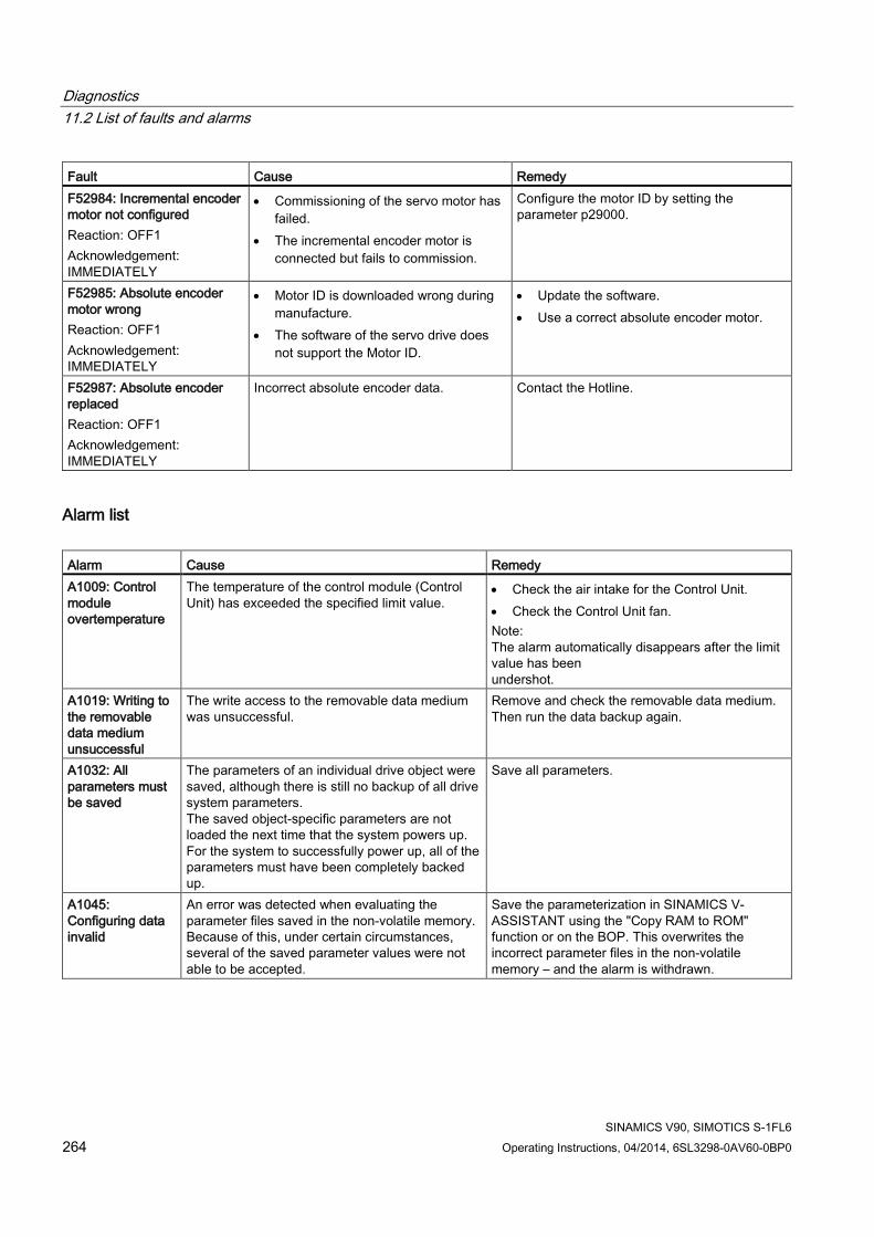
Diagnostics 11.2 List of faults and alarms
SINAMICS V90, SIMOTICS S-1FL6 264 Operating Instructions, 04/2014, 6SL3298-0AV60-0BP0
Fault Cause Remedy F52984: Incremental encoder motor not configured Reaction: OFF1 Acknowledgement: IMMEDIATELY
• Commissioning of the servo motor has failed.
• The incremental encoder motor is connected but fails to commission.
Configure the motor ID by setting the parameter p29000.
F52985: Absolute encoder motor wrong Reaction: OFF1 Acknowledgement: IMMEDIATELY
• Motor ID is downloaded wrong during manufacture.
• The software of the servo drive does not support the Motor ID.
• Update the software. • Use a correct absolute encoder motor.
F52987: Absolute encoder replaced Reaction: OFF1 Acknowledgement: IMMEDIATELY
Incorrect absolute encoder data. Contact the Hotline.
Alarm list Alarm Cause Remedy A1009: Control module overtemperature
The temperature of the control module (Control Unit) has exceeded the specified limit value.
• Check the air intake for the Control Unit. • Check the Control Unit fan. Note: The alarm automatically disappears after the limit value has been undershot.
A1019: Writing to the removable data medium unsuccessful
The write access to the removable data medium was unsuccessful.
Remove and check the removable data medium. Then run the data backup again.
A1032: All parameters must be saved
The parameters of an individual drive object were saved, although there is still no backup of all drive system parameters. The saved object-specific parameters are not loaded the next time that the system powers up. For the system to successfully power up, all of the parameters must have been completely backed up.
Save all parameters.
A1045: Configuring data invalid
An error was detected when evaluating the parameter files saved in the non-volatile memory. Because of this, under certain circumstances, several of the saved parameter values were not able to be accepted.
Save the parameterization in SINAMICS V-ASSISTANT using the "Copy RAM to ROM" function or on the BOP. This overwrites the incorrect parameter files in the non-volatile memory – and the alarm is withdrawn.

Diagnostics 11.2 List of faults and alarms
SINAMICS V90, SIMOTICS S-1FL6 Operating Instructions, 04/2014, 6SL3298-0AV60-0BP0 265
Alarm Cause Remedy A1920: Drive Bus: Receive setpoints after To
Output data of Drive Bus master (setpoints) received at the incorrect instant in time within the Drive Bus clock cycle.
• Check bus configuration. • Check parameters for clock cycle
synchronization (ensure To > Tdx). Note: To: Time of setpoint acceptance Tdx: Data exchange time
A1932: Drive Bus clock cycle synchronization missing for DSC
There is no clock synchronization or clock synchronous sign of life and DSC is selected. Note: DSC: Dynamic Servo Control
Set clock synchronization across the bus configuration and transfer clock synchronous sign-of-life.
A5000: Drive heat sink overtemperature
Cause: The alarm threshold for overtemperature at the inverter heat sink has been reached. If the temperature of the heat sink increases by an additional 5 K, then fault F30004 is initiated.
Check the following: • Is the surrounding temperature within the
defined limit values? • Have the load conditions and the load duty
cycle been appropriately dimensioned? • Has the cooling failed?
A7012: Motor temperature model 1/3 overtemperature
The motor temperature model 1/3 identified that the alarm threshold was exceeded.
• Check the motor load and reduce it if required. • Check the motor surrounding temperature.
A7441: LR: Save the position offset of the absolute encoder adjustment
The status of the absolute encoder adjustment has changed. In order to permanently save the determined position offset (p2525) it must be saved.
Not necessary. This alarm automatically disappears after the offset has been saved.
A7456: EPOS: Setpoint velocity limited
The actual setpoint velocity is greater than the parameterized maximum velocity and is therefore limited.
Decrease the actual setpoint velocity.
A7461: EPOS: Reference point not set
When starting a traversing block/direct setpoint input, a reference point is not set.
Reference the system (search for reference, flying referencing, set reference point).
A7469: EPOS: Traversing block < target position < software limit switch minus
In the traversing block the specified absolute target position lies outside the range limited by the software limit switch minus.
• Correct the traversing block. • Change software limit switch minus (p2580).
A7470: EPOS: Traversing block > target position > software limit switch plus
In the traversing block the specified absolute target position lies outside the range limited by the software limit switch plus.
• Correct the traversing block. • Change software limit switch plus (p2581).
A7471: EPOS: Traversing block target position outside the modulo range
In the traversing block the target position lies outside the modulo range.
• In the traversing block, correct the target position.
• Change the modulo range (p29246).

Diagnostics 11.2 List of faults and alarms
SINAMICS V90, SIMOTICS S-1FL6 266 Operating Instructions, 04/2014, 6SL3298-0AV60-0BP0
Alarm Cause Remedy A7472: EPOS: Traversing block ABS_POS/ABS_NEG not possible
In the traversing block the positioning mode ABS_POS or ABS_NEG were parameterized with the modulo correction not activated.
Correct the traversing block.
A7473: EPOS: Beginning of traversing range reached
When traversing, the axis has moved to the traversing range limit.
Move away in the positive direction.
A7474: EPOS: End of traversing range reached
When traversing, the axis has moved to the traversing range limit.
Move away in the negative direction.
A7477: EPOS: Target position < software limit switch minus
In the actual traversing operation, the target position is less than the software limit switch minus.
• Correct the target position. • Change software limit switch minus (CI:
p2580).
A7478: EPOS: Target position > software limit switch plus
In the actual traversing operation, the target position is greater than the software limit switch plus.
• Correct the target position. • Change software limit switch plus (CI: p2581).
A7479: EPOS: Software limit switch minus reached
The axis is at the position of the software limit switch minus. An active traversing block was interrupted.
• Correct the target position. • Change software limit switch minus (CI:
p2580).
A7480: EPOS: Software limit switch plus reached
The axis is at the position of the software limit switch plus. An active traversing block was interrupted.
• Correct the target position. • Change software limit switch plus (CI: p2581).
A7496: SON enable missing
In the PTI mode or a compound mode with PTI, the drive is in the servo off state.
Enable servo on for the drive.
A7576: Encoderless operation due to a fault active
Encoderless operation is active due to a fault. • Remove the cause of a possible encoder fault. • Carry out a POWER ON (power off/on) for all
components.
A7585: P-TRG or CLR active
In the PTI mode or a compound mode with PTI, the P-TRG or CLR function is activated.
In the PTI mode, deactivate the P-TRG or CLR function; in the compound mode with PTI, do not switch to other modes.
A7965: Save required
The angular commutation offset was re-defined and has still not been saved. In order to permanently accept the new value, it must be saved in a non-volatile fashion.
This alarm automatically disappears after the data has been saved.
A7971: Angular commutation offset determination activated
The automatic determination of the angular commutation offset (encoder adjustment) is activated. The automatic determination is carried out at the next power-on command.
The alarm automatically disappears after determination.

Diagnostics 11.2 List of faults and alarms
SINAMICS V90, SIMOTICS S-1FL6 Operating Instructions, 04/2014, 6SL3298-0AV60-0BP0 267
Alarm Cause Remedy A7991: Motor data identification activated
The motor data ident. routine is activated. The motor data identification routine is carried out at the next power-on command.
The alarm automatically disappears after the motor data identification routine has been successfully completed. If a POWER ON or a warm restart is performed with motor data identification selected, the motor data identification request will be lost. If motor data identification is required, it will need to be selected again manually following ramp-up.
A30016: Load supply switched off
The DC link voltage is too low. • Switch on the load supply. • Check the line supply if necessary.
A30031: Hardware current limiting in phase U
Hardware current limit for phase U responded. The pulsing in this phase is inhibited for one pulse period. • Closed-loop control is incorrectly
parameterized. • Fault in the motor or in the power cables. • The power cables exceed the maximum
permissible length. • Motor load too high. • Power unit defective. Note: Alarm A30031 is always output if, for a Power Module, the hardware current limiting of phase U, V or W responds.
Check the motor data. As an alternative, run a motor data identification. • Check the motor circuit configuration (star-
delta) • Check the motor load. • Check the power cable connections. • Check the power cables for short-circuit or
ground fault. • Check the length of the power cables.
A31411: Absolute encoder signals internal alarms
The absolute encoder fault word includes alarm bits that have been set.
Replace the encoder.
A31412: Error bit set in the serial protocol
The encoder sends a set error bit via the serial protocol.
• Carry out a POWER ON (power off/on) for all components.
• Check that the encoder cables are routed in compliance with EMC.
• Check the plug connections. • Replace the encoder.
A52900: Failure during data copying
• Copying is halted. • The SD card was plugged out. • The drive is not in the stop state.
• Re-plug in the SD card. • Make sure the drive is in the stop state.
A52901: Braking resistor reaches alarm threshold
The heat capacity reaches the threshold (p29005) of the braking resistor capacity.
• Change the external braking resistor. • Increase deceleration time.

Diagnostics 11.2 List of faults and alarms
SINAMICS V90, SIMOTICS S-1FL6 268 Operating Instructions, 04/2014, 6SL3298-0AV60-0BP0
Alarm Cause Remedy A52902: Emergency missing
Implement servo on when the emergency input (EMGS) is switched off.
Switch on the emergency input (EMGS) and then implement servo on.
A52932: PTO max limit
For incremental encoder, when PTO frequency exceeds 120K, drive will output A52932 to remind that exceed limitation. For absolute encoder, when PTO frequency exceeds 280K, drive will output A52932 to remind that exceed limitation.
Change PTO ratio.

SINAMICS V90, SIMOTICS S-1FL6 Operating Instructions, 04/2014, 6SL3298-0AV60-0BP0 269
Appendix A A.1 Order numbers
Siemens provides various drive package alternatives. You can order the desired package according to your particular demands. When placing a purchase order, you only need to indicate the package order number.
SINAMICS V90 servo drives Maximum supported motor power (kW) Order number 0.4 6SL3210-5FE10-4UA0 0.75 6SL3210-5FE10-8UA0 1.0 6SL3210-5FE11-0UA0 1.75 6SL3210-5FE11-5UA0 2.5 6SL3210-5FE12-0UA0 3.5 6SL3210-5FE13-5UA0 5.0 6SL3210-5FE15-0UA0 7.0 6SL3210-5FE17-0UA0
SIMOTICS S-1FL6 servo motors Rated torque (Nm)
Shaft height (mm)
Order number
1.27 45 1FL6042-1AF61-0 ❑ ❑ 1 2.39 1FL6044-1AF61-0 ❑ ❑ 1 3.58 65 1FL6061-1AC61-0 ❑ ❑ 1 4.78 1FL6062-1AC61-0 ❑ ❑ 1 7.16 1FL6064-1AC61-0 ❑ ❑ 1 8.36 1FL6066-1AC61-0 ❑ ❑ 1 9.55 1FL6067-1AC61-0 ❑ ❑ 1 11.90 90 1FL6090-1AC61-0 ❑ ❑ 1 16.70 1FL6092-1AC61-0 ❑ ❑ 1 23.90 1FL6094-1AC61-0 ❑ ❑ 1 33.40 1FL6096-1AC61-0 ❑ ❑ 1 Incremental encoder A Absolute encoder L Plain shaft end, without brake G Plain shaft end, with brake H Half key balanced shaft end, without brake A Half key balanced shaft end, with brake B
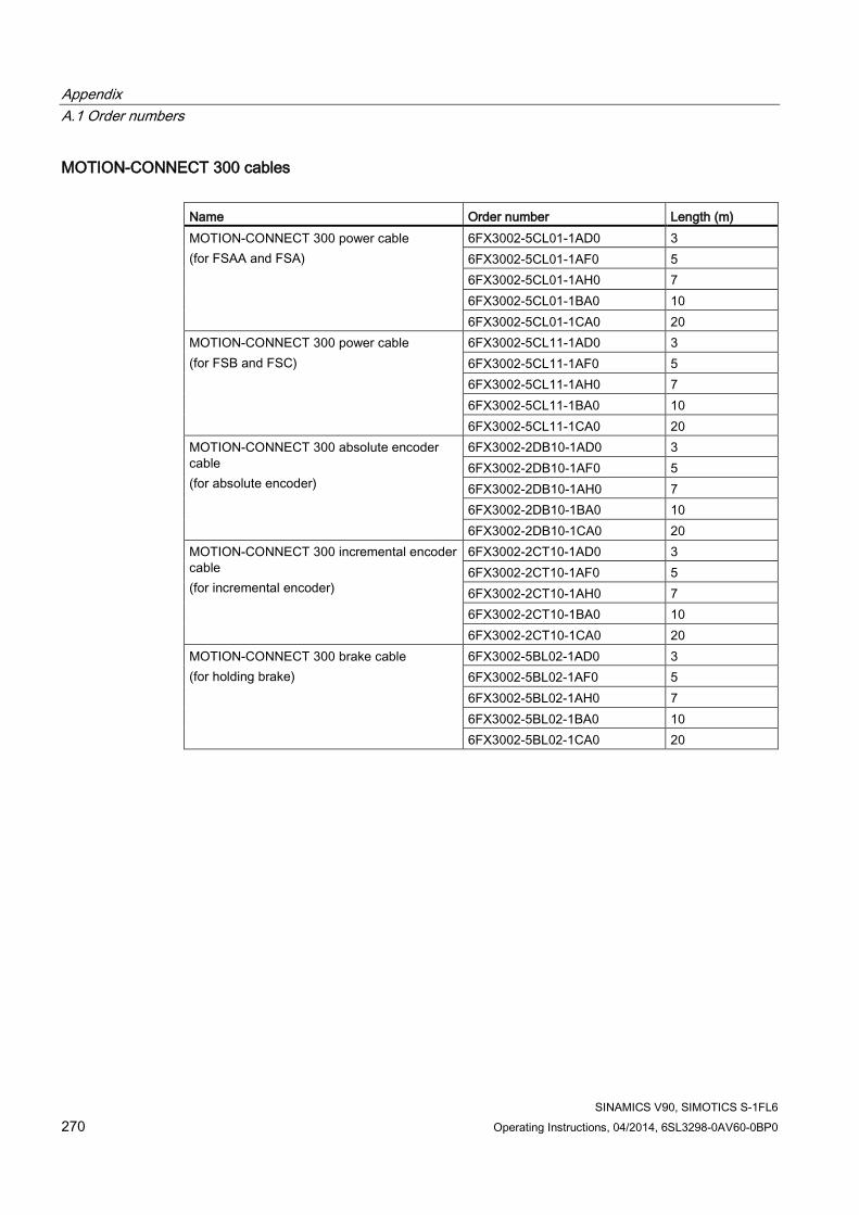
Appendix A.1 Order numbers
SINAMICS V90, SIMOTICS S-1FL6 270 Operating Instructions, 04/2014, 6SL3298-0AV60-0BP0
MOTION-CONNECT 300 cables Name Order number Length (m) MOTION-CONNECT 300 power cable (for FSAA and FSA)
6FX3002-5CL01-1AD0 3 6FX3002-5CL01-1AF0 5 6FX3002-5CL01-1AH0 7 6FX3002-5CL01-1BA0 10 6FX3002-5CL01-1CA0 20
MOTION-CONNECT 300 power cable (for FSB and FSC)
6FX3002-5CL11-1AD0 3 6FX3002-5CL11-1AF0 5 6FX3002-5CL11-1AH0 7 6FX3002-5CL11-1BA0 10 6FX3002-5CL11-1CA0 20
MOTION-CONNECT 300 absolute encoder cable (for absolute encoder)
6FX3002-2DB10-1AD0 3 6FX3002-2DB10-1AF0 5 6FX3002-2DB10-1AH0 7 6FX3002-2DB10-1BA0 10 6FX3002-2DB10-1CA0 20
MOTION-CONNECT 300 incremental encoder cable (for incremental encoder)
6FX3002-2CT10-1AD0 3 6FX3002-2CT10-1AF0 5 6FX3002-2CT10-1AH0 7 6FX3002-2CT10-1BA0 10 6FX3002-2CT10-1CA0 20
MOTION-CONNECT 300 brake cable (for holding brake)
6FX3002-5BL02-1AD0 3 6FX3002-5BL02-1AF0 5 6FX3002-5BL02-1AH0 7 6FX3002-5BL02-1BA0 10 6FX3002-5BL02-1CA0 20

Appendix A.1 Order numbers
SINAMICS V90, SIMOTICS S-1FL6 Operating Instructions, 04/2014, 6SL3298-0AV60-0BP0 271
Connectors Connector Order number Power connector (motor side) 6FX2003-0LL11 Absolute encoder connector (motor side) 6FX2003-0DB11 Incremental encoder connector (motor side) 6FX2003-0SL11 Brake connector (motor side) 6FX2003-0LL51 Encoder connector (drive side) 6FX2003-0SB14
Cable and connector (between V90 drive and controller) Name Order number Length (m) Option 1 Setpoint connector (50 pins) 6SL3260-2NA00-0VA0 - Setpoint cable (50 pins) 6SL3260-4NA00-1VB0 1 Option 2 Setpoint cable with terminal block (50 pins) 6SL3260-4NA00-1VA5 0.5
User documentation Name Language version Order number Operating Instructions English 6SL3298-0AV60-0BP0
Chinese 6SL3298-0AV60-0FP0 Italian 6SL3298-0AV60-0CP0
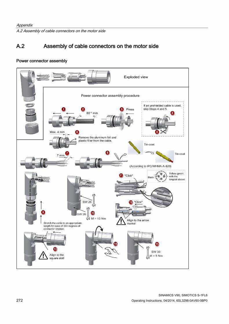
Appendix A.2 Assembly of cable connectors on the motor side
SINAMICS V90, SIMOTICS S-1FL6 272 Operating Instructions, 04/2014, 6SL3298-0AV60-0BP0
A.2 Assembly of cable connectors on the motor side
Power connector assembly

Appendix A.2 Assembly of cable connectors on the motor side
SINAMICS V90, SIMOTICS S-1FL6 Operating Instructions, 04/2014, 6SL3298-0AV60-0BP0 273
Encoder connector assembly The connector assembly procedures for incremental and absolute encoders are the same.

Appendix A.3 Assembly of cable terminals on the drive side
SINAMICS V90, SIMOTICS S-1FL6 274 Operating Instructions, 04/2014, 6SL3298-0AV60-0BP0
Brake connector assembly The assembly of a brake connector follows the procedure as described in the figure above for an encoder connector.
A.3 Assembly of cable terminals on the drive side
Power terminal assembly Drive type Procedure Illustration FSA/FSAA Terminal assembly procedure:
1. Remove the outer sheath of the cable. 2. Remove the insulation from the wire. 3. Insert the stripped end into the cable end
sleeve. 4. Crimp the cable end sleeve using a crimp
tool for end sleeves.
FSB/FSC Terminal assembly procedure: 1. Remove the outer sheath of the cable. 2. Remove the insulation from the wire. 3. Insert the stripped end into the spade
terminal. 4. Crimp the spade terminal using a crimp tool
for cable lugs. (Note: Coat any exposed wires with tin.)

Appendix A.3 Assembly of cable terminals on the drive side
SINAMICS V90, SIMOTICS S-1FL6 Operating Instructions, 04/2014, 6SL3298-0AV60-0BP0 275
Encoder terminal assembly The terminal assembly procedures for incremental and absolute encoders are the same.

Appendix A.4 Motor selection
SINAMICS V90, SIMOTICS S-1FL6 276 Operating Instructions, 04/2014, 6SL3298-0AV60-0BP0
Brake terminal assembly The assembly of a brake terminal follows the procedure as described in the figure above for a power terminal.
A.4 Motor selection
A.4.1 Selection procedure 1. Determine the mechanism type as well as the detailed data of the related mechanical
parts, such as ball screw lead, diameter, lead, and gear diameter. Three mechanism types are shown below:
Belt transmission
Ball screw
Rack and pinion and/or gear
2. Determine the operation pattern including such parameters as acceleration time (ta), constant motion time (tu), deceleration time (td), stopping time (ts), cycle time (tc), and travel distance (L).
3. Calculate load inertia and inertia ratio.
The inertia ratio can be obtained by dividing the load inertia by the rotor inertia of the selected motor. The unit of inertia is x 10-4 kg·m2.
4. Calculate the speed. Calculate the speed according to the travel distance, acceleration time, deceleration time, and constant motion time.

Appendix A.4 Motor selection
SINAMICS V90, SIMOTICS S-1FL6 Operating Instructions, 04/2014, 6SL3298-0AV60-0BP0 277
5. Calculate the torque. Calculate the torque according to the load inertia, acceleration time, deceleration time, and constant motion time.
6. Select the motor. Select the motor that matches the data in step 3 to step 5.
A.4.2 Parameter description
Torque ● Summit torque: It refers to the maximum torque required by a motor in operation, which is
generally less than 80% of the motor’s maximum torque. When the torque is a negative value, regenerative resistors may be needed.
● Moving torque and hold torque in standstill: It refers to the torque required by a motor in long-term operation, which is generally less than 80% of the motor’s rated torque. When the torque is a negative value, regenerative resistors may be needed. Torque calculation methods of two major mechanism types:
W: Mass [kg] Pb: Ball screw lead [m] F: External force [N]
η: Mechanical efficiency μ: Friction coefficient g: Gravitational acceleration 9.8 [m/s2]
W: Mass [kg] Pd: Belt transmission lead [m] F: External force [N]
η: Mechanical efficiency μ: Friction coefficient g: Gravitational acceleration 9.8 [m/s2]
● Effective torque: It refers to the continuous effective load torque converted into the equivalent value on the servo motor shaft, which is generally less than 80% of the motor’s rated torque.

Appendix A.4 Motor selection
SINAMICS V90, SIMOTICS S-1FL6 278 Operating Instructions, 04/2014, 6SL3298-0AV60-0BP0
Ta: Acceleration torque [N·m] Tm: Moving torque [N·m] Td: Deceleration torque [N·m]
ta: Acceleration time [s] tu: Constant motion time [s] td: Deceleration time [s]
tc: Cycle time [s]
Speed Maximum speed: It refers to the motor's maximum speed in operation, which is generally lower than the rated speed. When a motor operates at the maximum speed, pay attention to its torque and temperature rise.
Inertia and inertia ratio Inertia refers to the force required to keep a certain physical state. Inertia ratio indicates dynamic response performance of motors. The smaller the inertia ratio is, the better response performance a motor has.
Typical load inertia equations Mechanism Equation Mechanism Equation
Axis of rotation on center
W: Mass (kg) a: Length (m) b: Width (m)
Axis of rotation on center
W: Mass (kg) D1: External diameter (m) D2: Internal diameter (m)
Axis of rotation off center
W: Mass (kg) a: Length (m) b: Width (m) R: Rotational diameter (m)
Axis of rotation off center
W: Mass (kg) D: Workpiece diameter (m) R: Rotational diameter (m)

Appendix A.4 Motor selection
SINAMICS V90, SIMOTICS S-1FL6 Operating Instructions, 04/2014, 6SL3298-0AV60-0BP0 279
Mechanism Equation Mechanism Equation
Conveyor
W: Mass (kg) D: Pulley wheel diameter (m)
Ball screw
W: Mass (kg) P: Lead (m) Jb: Ball screw inertia (kg·m2)
Object hung with pulley
W: Mass (kg) D: Pulley wheel diameter (m) Jp: Pulley inertia (kg·m2)
Reducer
W: Mass (kg) n1/n2: Speed of each motor (rpm) J1 /J2: Inertia of each motor (kg·m2)
A.4.3 Selection examples This section uses a ball screw mechanism as an example to illustrate the motor selection procedure.
Exemplary data The following table lists the data related to the ball screw mechanism and operation pattern.
Mechanism Operation pattern Workpiece weight (W) 40 kg Acceleration time (ta) 0.15 s Ball screw length (Bl) 2 m Constant motion time (tu) 0.7 s Ball screw diameter (Bd) 0.04 m Deceleration time (td) 0.15 s Ball screw pitch (Bp) 0.04 m Cycle time (tc) 2 s Mechanical efficiency (Bŋ) 0.9 Travel distance (L) 0.5 m Coupler inertia (Jc) 20 x 10-6 kg·m2 (refer to
the supplier's product catalog)
-
1. Ball screw weight Bw = ρ x π x (Bd/2)2 x Bl = 19.85 kg
2. Load inertia Jl = Jc + Jb = Jc + 1/8 x Bw x Bd2 + W x Bp2 / 4π2 = 5.61 x 10⁻³ kg·m2
3. Preselection If a 1000 W motor is selected, Jm (motor inertia) = 1.57 x 10⁻³ kg·m2 Therefore, Jl / Jm (inertia ratio) = 3.57 < 5 times
4. Maximum rotational speed Vmax (maximum travelling speed) = 2L / (ta + 2tu + td) = 5.89 m/s Nmax (maximum rotational speed) = 60 x Vmax / Bp = 882 rpm < 2000 rpm (rated speed)
5. Effective torque Tm (moving torque) = (μgW + F) x Bp / 2πBη = 0.069 Nm

Appendix A.5 Replacing fans
SINAMICS V90, SIMOTICS S-1FL6 280 Operating Instructions, 04/2014, 6SL3298-0AV60-0BP0
Ta (acceleration torque) = [(Jl + Jm) x 2 πN / Ta] + Tm = 4.49 Nm Td (deceleration torque) = [(Jl + Jm) x 2 πN / Td] - Tm = 4.35 Nm Therefore, Trms (effective torque) =√(Ta2 x ta + Tm2 x tb + Td2 x td) / tc = 1.71 Nm < 4.78 Nm (rated torque)
6. Final selection According to the above calculated speed, torque, and inertia ratio, you are recommended to select 1000 W motors, i.e. 1FL6062.
A.5 Replacing fans Proceed as illustrated below to remove the fan from the SINAMICS V90 drive. To re-assemble the fan, proceed in reverse order. When re-assembling the fan for FSC, make sure that the arrow symbol (" "in the illustration) on the fan points to the drive rather than the fan housing.

Appendix A.5 Replacing fans
SINAMICS V90, SIMOTICS S-1FL6 Operating Instructions, 04/2014, 6SL3298-0AV60-0BP0 281
Replacing the fans from frame size B

Appendix A.5 Replacing fans
SINAMICS V90, SIMOTICS S-1FL6 282 Operating Instructions, 04/2014, 6SL3298-0AV60-0BP0
Replacing the fan from frame size C
SINAMICS V90, SIMOTICS S-1FL6 Operating Instructions, 04/2014, 6SL3298-0AV60-0BP0 283
Index
A
Absolute position system Telegram format, 173
Accessories Braking resistor, 33 Cables and connectors, 31 External 24 VDC power supply, 32 Filter, 34 Fuse/Circuit breaker, 33 SD card, 35
Aims, 175 Ajust AI offset, 123 analog inputs, 70 Analog inputs
Command voltage, 71 analog outputs, 71 Analog outputs
Parameterization, 71 Wiring, 72
ANSI B11, 186
B
Backlash compensation, 150 BOP operations
Button functions, 110 BOP operations for faults and alarms, 250
Acknowledging faults, 251 Exiting from alarm display, 251 Exiting from fault display, 250 Viewing alarms, 250 Viewing faults, 250
BOP overview, 107
C
Certification, 188 Change a parameter value, 113
Parameter setting with shift function, 115 Commissioning
SINAMICS V-ASSISTANT, 97 Connecting 24 V power supply/STO, 90 Connecting an external braking resistor, 94 Connecting the RS485 interface, 95 Connecting the SIMATIC S7-1200
For internal position control (IPos), 87 For pulse train input position control (PTI), 86 For speed control (S), 88 For torque control (T), 89
Connecting the SIMATIC S7-200 For internal position control (IPos), 83 For pulse train input position control (PTI), 82 For speed control, 84 For torque control, 85
Connecting the SIMATIC S7-200 SMART For internal position control (IPos), 79 For pulse train input position control (PTI), 78 For speed control (S), 80 For torque control (T), 81
Copy parameter set from an SD card to drive, 121 Copy parameters from the servo drive to an SD card, 120
D
Device combination, 27 Differences between faults and alarms, 249 Digital inputs, 62
Direct signal map, 65 Wiring, 66
Digital outputs, 66 Assigning warning signals to digital outputs, 68
DIN EN ISO 13849-1, 179 Direction of motor rotation, 127 Drive components, 23 Drive rating plate, 24
E
EN 61508, 181 EN 62061, 180 Equipment regulations, 187
F
Function list, 35 Functional safety, 176
G
Gain switch, 206

Index
SINAMICS V90, SIMOTICS S-1FL6 284 Operating Instructions, 04/2014, 6SL3298-0AV60-0BP0
Gain switching using actual speed, 210 Gain switching using an external digital input signal, 207 Gain switching using position deviation, 208 Gain switching using position setpoint frequency, 209
H
Harmonized European Standards, 177
I Internal position control mode (IPos)
Linear/modular axis, 150 Position setpoint, 147 Selecting a fixed position setpoint and starting positioning, 160 Selecting a positioning mode, 149 Setting mechanical system, 146 Software position limit, 159
J
JOG, 98 Jog function, 118
Jog in speed, 118 Jog in torque, 118
L
LED status indicators, 252
M
Machine safety in Japan, 187 Machine safety in the USA, 184 Machinery directive, 176 Main circuit wirings
Connecting the motor power - U, V, W, 58 Motor holding brake, 130
DO setting, 130 Parameter setting, 131
Motor selection method, 276 Mounting the motor
Motor dimensions, 49 Mounting orientation, 49
N
NFPA 79, 185 NRTL, 185
O
Operating display, 112 OSHA, 184 Over-travel, 128 Overview of absolute position system, 172
Restrictions, 172 Overview of SINAMICS V90 BOP functions, 117
P
PI to P switching using torque setpoint, 212 PI/P switching, 210 PI/P switching using acceleration setpoint, 214 PI/P switching using an external digital input signal, 213 PI/P switching using pulse deviation, 215 PI/P switching using speed setpoint, 214 Preface
Documentation components, 3 Target group, 3 Technical support, 3
Probabilty of failure, 190 PTO
Wiring, 70 Pulse train encoder outputs, 70 Pulse train input position control mode (PTI)
Calculating electronic gear ratio, 136 Clearing droop pulses, 144 In position (INP), 134 P-TRG, 139 Selecting a setpoint pulse train input channel, 133 Selecting a setpoint pulse train input form, 133 Smoothing function, 135
Pulse train inputs Wiring, 69
R
Referencing Referencing modes, 151
Residual risk, 184 Resonance suppression, 203
Manual input of resonance frequency (p29023=0), 205

Index
SINAMICS V90, SIMOTICS S-1FL6 Operating Instructions, 04/2014, 6SL3298-0AV60-0BP0 285
One-time resonance frequency search with excitation (p29023=2), 205 Real-time resonance suppression (p29023=1), 204 Select a resonance suppression mode, 203
Response time, 190 Risk analysis, 182 Risk reduction, 183
S
Safe Torque Off functional features, 191 response time, 193 selecting/deselecting STO, 193
Safety Integrated function, 187 Safety of machinery in Europe, 176 Save parameters in the servo drive, 119 Search a parameter in "P ALL" menu, 116 Selection of control mode
Control mode change for a compound control mode, 125 Control modes, 125 Selection of a basic control mode, 125
Servo ON signal, 126 Relevant parameter settings, 127
Set parameter set to default, 119 Set zero position, 124 Speed control mode
Direction and stop, 165 External speed setpoint, 163 Offset adjustment, 164 Parameter settings for fixed speed setpoint, 164 Ramp-function generator, 167 Speed setpoint, 162 Zero speed clamp, 166
Speed limit, 140 Overall speed limit, 140
Standards for implementing safety-related controllers, 178 Stopping method at servo OFF, 132
Coast-down (OFF2), 132 Emergency stop (OFF3), 133 Ramp-down (OFF1), 132
System connection, 55
T
Technical data Cables, 44 servo motors, 39
Torque control mode
300% overload capacity, 168 Direction and stop, 171 External analog torque setpoint, 170 External speed limit, 141 Internal speed limit, 141 Offset adjustment, 170 Torque control with fixed setpoint, 171 Torque setpoint, 169
Torque limit, 141 External torque limit, 143 Internal torque limit, 142 Overall torque limit, 142 Torque limit reached (TLR), 144
Transmitting sequence for the absolute position data, 173 Tuning
Basic tuning procedure, 198 Configuration of dynamic factor, 198 Manual tuning, 201 Real-time auto tuning, 200 Servo gains, 196 Tuning methods, 197 Tuning with SINAMICS V-ASSISTANT, 197
U
Update firmware, 122 Usage of the shielding plate, 56
W
Wiring and connecting Adjusting cable orientations, 57
Wiring and connection Connecting the encoder - X9, 91 Connecting the motor holding brake - X7, 94

Index
SINAMICS V90, SIMOTICS S-1FL6 286 Operating Instructions, 04/2014, 6SL3298-0AV60-0BP0