sinamics v-assistant online help - siemens · 2.1 sinamics v-assistant operating environment ......
TRANSCRIPT

SINAMICS V-ASSISTANT Online Help
___________________
___________________
___________________
___________________
SINAMICS
SINAMICS V90 SINAMICS V-ASSISTANT Online Help
Operating Manual
04/2014 A5E32187373-002
Preface 1
SINAMICS V-ASSISTANT 2
User interface 3
Task navigation 4

Siemens AG Industry Sector Postfach 48 48 90026 NÜRNBERG GERMANY
A5E32187373-002 Ⓟ 05/2014 Subject to change
Copyright © Siemens AG 2013 - 2014. All rights reserved
Legal information Warning notice system
This manual contains notices you have to observe in order to ensure your personal safety, as well as to prevent damage to property. The notices referring to your personal safety are highlighted in the manual by a safety alert symbol, notices referring only to property damage have no safety alert symbol. These notices shown below are graded according to the degree of danger.
DANGER indicates that death or severe personal injury will result if proper precautions are not taken.
WARNING indicates that death or severe personal injury may result if proper precautions are not taken.
CAUTION indicates that minor personal injury can result if proper precautions are not taken.
NOTICE indicates that property damage can result if proper precautions are not taken.
If more than one degree of danger is present, the warning notice representing the highest degree of danger will be used. A notice warning of injury to persons with a safety alert symbol may also include a warning relating to property damage.
Qualified Personnel The product/system described in this documentation may be operated only by personnel qualified for the specific task in accordance with the relevant documentation, in particular its warning notices and safety instructions. Qualified personnel are those who, based on their training and experience, are capable of identifying risks and avoiding potential hazards when working with these products/systems.
Proper use of Siemens products Note the following:
WARNING Siemens products may only be used for the applications described in the catalog and in the relevant technical documentation. If products and components from other manufacturers are used, these must be recommended or approved by Siemens. Proper transport, storage, installation, assembly, commissioning, operation and maintenance are required to ensure that the products operate safely and without any problems. The permissible ambient conditions must be complied with. The information in the relevant documentation must be observed.
Trademarks All names identified by ® are registered trademarks of Siemens AG. The remaining trademarks in this publication may be trademarks whose use by third parties for their own purposes could violate the rights of the owner.
Disclaimer of Liability We have reviewed the contents of this publication to ensure consistency with the hardware and software described. Since variance cannot be precluded entirely, we cannot guarantee full consistency. However, the information in this publication is reviewed regularly and any necessary corrections are included in subsequent editions.

SINAMICS V-ASSISTANT Online Help Operating Manual, 04/2014, A5E32187373-002 3
Table of contents
1 Preface ................................................................................................................................................... 5
2 SINAMICS V-ASSISTANT ...................................................................................................................... 7
2.1 SINAMICS V-ASSISTANT operating environment ........................................................................ 7
2.2 Device combination ........................................................................................................................ 8
3 User interface ......................................................................................................................................... 9
3.1 Working modes .............................................................................................................................. 9
3.2 User interface - overview ............................................................................................................. 14
3.3 Menu bar ...................................................................................................................................... 15 3.3.1 Menu bar - overview .................................................................................................................... 15 3.3.2 Project menu ................................................................................................................................ 15 3.3.2.1 Project -> New project .................................................................................................................. 15 3.3.2.2 Project -> Open project ................................................................................................................ 16 3.3.2.3 Project -> Save project ................................................................................................................. 17 3.3.2.4 Project -> Save project as... ......................................................................................................... 18 3.3.2.5 Project -> Print ............................................................................................................................. 18 3.3.2.6 Project -> Language ..................................................................................................................... 18 3.3.2.7 Project -> Exit ............................................................................................................................... 19 3.3.3 Edit menu ..................................................................................................................................... 19 3.3.3.1 Edit -> Cut .................................................................................................................................... 19 3.3.3.2 Edit -> Copy ................................................................................................................................. 19 3.3.3.3 Edit -> Paste ................................................................................................................................ 20 3.3.4 Switch menu ................................................................................................................................. 20 3.3.4.1 Switch -> Go offline ...................................................................................................................... 20 3.3.4.2 Switch -> Go online ...................................................................................................................... 20 3.3.5 Tools menu .................................................................................................................................. 20 3.3.5.1 Tools -> Save parameters to ROM .............................................................................................. 21 3.3.5.2 Tools -> Reset drive ..................................................................................................................... 21 3.3.5.3 Tools -> Reset absolute encoder ................................................................................................. 22 3.3.5.4 Tools -> Factory default ............................................................................................................... 22 3.3.5.5 Tools -> Upload parameters ........................................................................................................ 24 3.3.6 Help menu .................................................................................................................................... 24 3.3.6.1 Help -> View help ......................................................................................................................... 24 3.3.6.2 Help -> About SINAMICS V-ASSISTANT... ................................................................................. 25
3.4 Toolbar ......................................................................................................................................... 25
3.5 Alarm window ............................................................................................................................... 26
3.6 Function keys and shortcuts ........................................................................................................ 26
4 Task navigation ..................................................................................................................................... 27
4.1 Selecting drive.............................................................................................................................. 28 4.1.1 Selecting drive.............................................................................................................................. 29 4.1.2 Selecting motor ............................................................................................................................ 31

Table of contents
SINAMICS V-ASSISTANT Online Help 4 Operating Manual, 04/2014, A5E32187373-002
4.1.3 Control mode ............................................................................................................................... 32 4.1.4 Jog ............................................................................................................................................... 34
4.2 Parameterizing ............................................................................................................................ 36 4.2.1 Setting electronic gear ratio ........................................................................................................ 37 4.2.1.1 Overview ..................................................................................................................................... 37 4.2.1.2 Mechanical structure ................................................................................................................... 38 4.2.2 Setting mechanism ...................................................................................................................... 39 4.2.3 Setting parameter setpoint .......................................................................................................... 40 4.2.3.1 Torque setpoint ........................................................................................................................... 41 4.2.3.2 Speed setpoint ............................................................................................................................ 41 4.2.3.3 Position setpoint .......................................................................................................................... 44 4.2.4 Setting limits ................................................................................................................................ 47 4.2.4.1 Torque limit.................................................................................................................................. 48 4.2.4.2 Speed limit................................................................................................................................... 49 4.2.5 Configuring inputs/outputs .......................................................................................................... 50 4.2.5.1 Assigning digital inputs ................................................................................................................ 50 4.2.5.2 Assigning digital outputs ............................................................................................................. 51 4.2.5.3 Assigning analog outputs ............................................................................................................ 51 4.2.6 Configuring referencing ............................................................................................................... 52 4.2.6.1 Setting referencing ...................................................................................................................... 52 4.2.6.2 Setting software position limit...................................................................................................... 56 4.2.7 Setting pulse train encoder output .............................................................................................. 57 4.2.8 Backlash compensation .............................................................................................................. 58 4.2.9 Viewing all parameters ................................................................................................................ 59
4.3 Commissioning ............................................................................................................................ 61 4.3.1 Testing interface .......................................................................................................................... 61 4.3.1.1 I/O simulation .............................................................................................................................. 61 4.3.1.2 Status of DI signals ..................................................................................................................... 63 4.3.1.3 Digital inputs (DIs) ....................................................................................................................... 63 4.3.1.4 Digital outputs (DOs) ................................................................................................................... 67 4.3.1.5 Analog inputs (AIs) ...................................................................................................................... 70 4.3.1.6 Analog outputs (AOs) .................................................................................................................. 70 4.3.1.7 Pulse train inputs (PTIs) .............................................................................................................. 71 4.3.1.8 Pulse train encoder outputs (PTOs) ............................................................................................ 71 4.3.2 Testing motor .............................................................................................................................. 71 4.3.2.1 Jog ............................................................................................................................................... 72 4.3.2.2 Position trial run .......................................................................................................................... 72 4.3.3 Optimizing drive .......................................................................................................................... 73 4.3.3.1 Manual tuning .............................................................................................................................. 74 4.3.3.2 Real-time auto tuning .................................................................................................................. 76
4.4 Diagnostics .................................................................................................................................. 78 4.4.1 Monitoring status ......................................................................................................................... 78 4.4.2 Tracing signals ............................................................................................................................ 79 4.4.2.1 Trace configuration ..................................................................................................................... 81 4.4.3 Measuring machine ..................................................................................................................... 83
Index .................................................................................................................................................... 87

SINAMICS V-ASSISTANT Online Help Operating Manual, 04/2014, A5E32187373-002 5
Preface 1
Technical support Country Hotline China +86 400 810 4288 Germany +49 (0) 911 895 7222 Italy +39 (02) 24362000 India +91 22 2760 0150 Turkey +90 (216) 4440747 Further service contact information: Support contacts (http://support.automation.siemens.com/WW/view/en/16604999)

Preface
SINAMICS V-ASSISTANT Online Help 6 Operating Manual, 04/2014, A5E32187373-002

SINAMICS V-ASSISTANT Online Help Operating Manual, 04/2014, A5E32187373-002 7
SINAMICS V-ASSISTANT 2
SINAMICS V-ASSISTANT engineering tool is designed for faster commissioning and diagnostics for SINAMICS V90 drive. The software runs on a personal computer with Windows operating systems and utilizes graphical user interface to interact with users and communicates with V90 drive via USB. It can be used to modify parameters and monitor status of SINAMICS V90 drive.
2.1 SINAMICS V-ASSISTANT operating environment SINAMICS V-ASSISTANT runs on the following operating systems:
● Windows XP SP3 (Home)
● Windows XP SP3 (Professional)
● Windows 7 32 bit (Home Premium)
● Windows 7 32 bit (Professional)
● Windows 7 32 bit (Ultimate)
● Windows 7 64 bit (Home Premium)
● Windows 7 64 bit (Professional)
● Windows 7 64 bit (Ultimate)
Note
The minimum screen resolution must be 1024*768.

SINAMICS V-ASSISTANT 2.2 Device combination
SINAMICS V-ASSISTANT Online Help 8 Operating Manual, 04/2014, A5E32187373-002
2.2 Device combination The table below shows the combination of SINAMICS V90 servo drives and SIMOTICS S-1FL6 servo motors.
SIMOTICS S-1FL6 servo motor SINAMICS V90 servo drive
Rated torque (Nm)
Rated power (kW)
Rated speed (rpm)
Shaft height (mm)
Order number1) Order number Frame size
1.27 0.4 3000 45 1FL6042-1AF61-0❑❑1
6SL3210-5FE10-4UA0
FSAA
2.39 0.75 3000 45 1FL6044-1AF61-0❑❑1
6SL3210-5FE10-8UA0
FSA
3.58 0.75 2000 65 1FL6061-1AC61-0❑❑1
6SL3210-5FE11-0UA0 4.78 1.0 2000 65 1FL6062-1AC61-
0❑❑1 7.16 1.5 2000 65 1FL6064-1AC61-
0❑❑1 6SL3210-5FE11-5UA0
FSB 8.36 1.75 2000 65 1FL6066-1AC61-0❑❑1
9.55 2.0 2000 65 1FL6067-1AC61-0❑❑1
6SL3210-5FE12-0UA0
11.9 2.5 2000 90 1FL6090-1AC61-0❑❑1
16.7 3.5 2000 90 1FL6092-1AC61-0❑❑1
6SL3210-5FE13-5UA0
FSC
23.9 5.0 2000 90 1FL6094-1AC61-0❑❑1
6SL3210-5FE15-0UA0
33.4 7.0 2000 90 1FL6096-1AC61-0❑❑1
6SL3210-5FE17-0UA0
The symbol ❑❑ in the motor order numbers is for optional configurations (encoder type and mechanics). For detailed motor rating plate explanation, refer to SINAMICS V90, SIMOTICS S-1FL6 Operating Instructions.

SINAMICS V-ASSISTANT Online Help Operating Manual, 04/2014, A5E32187373-002 9
User interface 3 3.1 Working modes
When you start the SINAMICS V-ASSISTANT, the following window appears for you to select a working mode:
The functions of SINAMICS V-ASSISTANT vary with the working modes.
● Online mode: SINAMICS V-ASSISTANT communicates with the target drive, which is connected with PC by a USB cable.
Select the online mode, a list of all the connected drives is displayed. Select the target drive and click the following button.
SINAMICS V-ASSISTANT automatically creates a new project to save all the parameter settings from the target drive and enters the main window.
Note
If SINAMICS V-ASSISTANT fails to detect the connected drive immediately, please wait for a while and then plug in the USB cable again.

User interface 3.1 Working modes
SINAMICS V-ASSISTANT Online Help 10 Operating Manual, 04/2014, A5E32187373-002
● Offline mode: SINAMICS V-ASSISTANT does not communicate with any connected drive.
Two options are available for your choice:
– If you select the first option, you must select a drive from the following window:
Select the line supply and firmware version from the drop-down lists respectively. Select the order number of a drive. Click to save the factory settings of the selected drive to the new project and enter the main window; or otherwise, click to cancel.
Note
To obtain the firmware version, you can view r29018 on BOP (Basic Operator Panel). For more information, refer to SINAMICS V90, SIMOTICS S-1FL6 Operating Instructions.

User interface 3.1 Working modes
SINAMICS V-ASSISTANT Online Help Operating Manual, 04/2014, A5E32187373-002 11
– If you select the second option, you need to select an existing project in the following directory as the current project and enter the main window:
① The default location is: xxx/Siemens/SINAMICS V-ASSISTANT/Project. xxx: SINAMICS V-ASSISTANT setup root directory.
② Only .prj format is available.
Status indicators In the SINAMICS V-ASSISTANT main window, the current working mode is indicated by the status indicators at the upper right of the main window:
Online
Offline
You can switch the working mode between the two modes. For more information, refer to Section "Switch menu (Page 20)".
User interface 3.1 Working modes
SINAMICS V-ASSISTANT Online Help 12 Operating Manual, 04/2014, A5E32187373-002
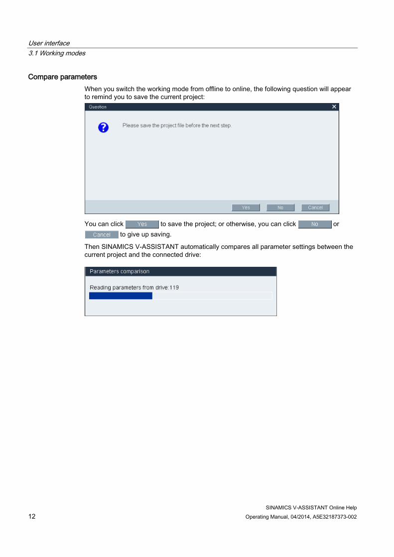
Compare parameters When you switch the working mode from offline to online, the following question will appear to remind you to save the current project:
You can click to save the project; or otherwise, you can click or to give up saving.
Then SINAMICS V-ASSISTANT automatically compares all parameter settings between the current project and the connected drive:

User interface 3.1 Working modes
SINAMICS V-ASSISTANT Online Help Operating Manual, 04/2014, A5E32187373-002 13
If any inconsistency is detected, the following window will appear:
Click the first button to upload all parameter values of the connected drive to the current project; or otherwise, click the second button to upload all parameter values of the current project to the connected drive.
User interface 3.2 User interface - overview
SINAMICS V-ASSISTANT Online Help 14 Operating Manual, 04/2014, A5E32187373-002
3.2 User interface - overview
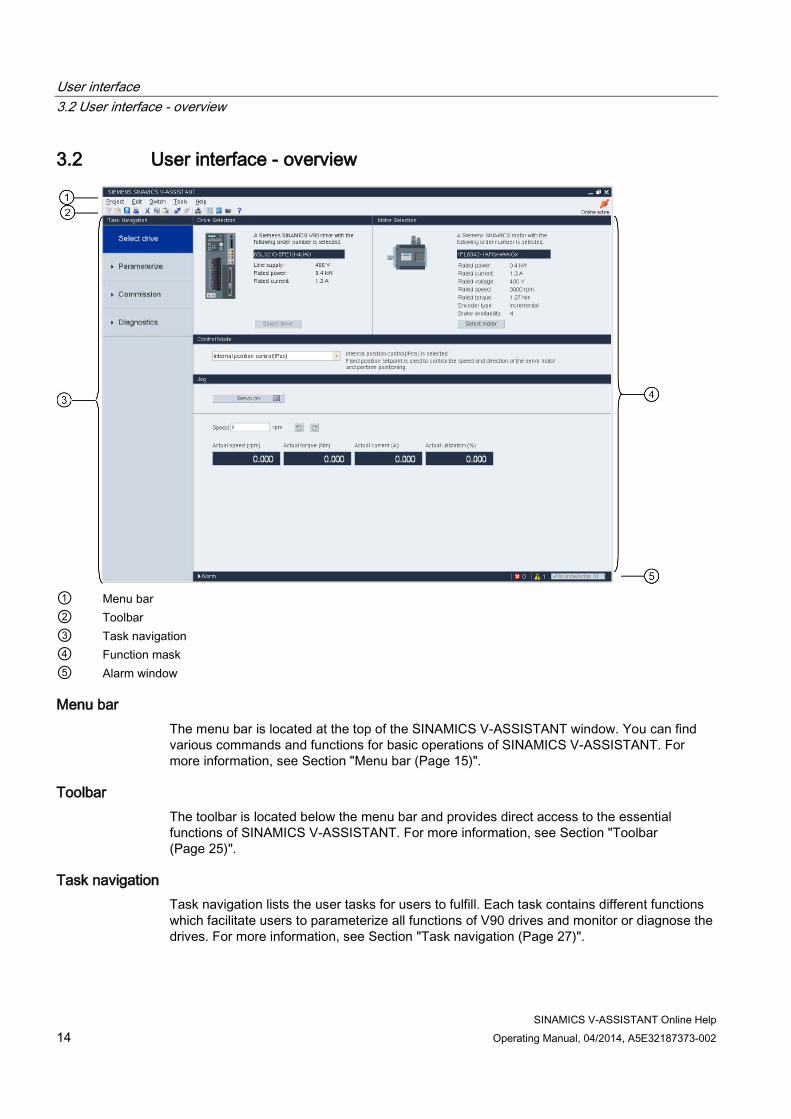
① Menu bar ② Toolbar ③ Task navigation ④ Function mask ⑤ Alarm window
Menu bar The menu bar is located at the top of the SINAMICS V-ASSISTANT window. You can find various commands and functions for basic operations of SINAMICS V-ASSISTANT. For more information, see Section "Menu bar (Page 15)".
Toolbar The toolbar is located below the menu bar and provides direct access to the essential functions of SINAMICS V-ASSISTANT. For more information, see Section "Toolbar (Page 25)".
Task navigation Task navigation lists the user tasks for users to fulfill. Each task contains different functions which facilitate users to parameterize all functions of V90 drives and monitor or diagnose the drives. For more information, see Section "Task navigation (Page 27)".

User interface 3.3 Menu bar
SINAMICS V-ASSISTANT Online Help Operating Manual, 04/2014, A5E32187373-002 15
Function mask The function mask provides the user interface of each user task for users to implement related functions.
Alarm window In online mode, the current faults and alarms are displayed in a list with the corresponding type, number and name. In offline mode, the alarm window is disabled. For more information, see Section "Alarm window (Page 26)".
3.3 Menu bar
3.3.1 Menu bar - overview The menu bar lists the menu items for users to manage the projects, switch the interface language, or view the online help:
Project menu (Page 15)
Edit menu (Page 19)
Switch menu (Page 20)
Tools menu (Page 20)
Help menu (Page 24)
3.3.2 Project menu This menu contains commands for creating, opening, saving, printing,or exiting from a project as well as switching the interface language. You can choose any menu command here for project management.
● New project (Page 15)
● Open project (Page 16)
● Save project (Page 17)
● Save project as (Page 18)
● Print (Page 18)
● Language (Page 18)
● Exit (Page 19)
3.3.2.1 Project -> New project When SINAMICS V-ASSISTANT is working in offline mode, you can use this menu command to create a new project. To proceed, refer to Selecting drive (Page 29).

User interface 3.3 Menu bar
SINAMICS V-ASSISTANT Online Help 16 Operating Manual, 04/2014, A5E32187373-002
3.3.2.2 Project -> Open project When SINAMICS V-ASSISTANT is working in offline mode, you can use this menu command to open an existing project in the following window:
① The default location is: xxx/Siemens/SINAMICS V-ASSISTANT/Project. xxx: SINAMICS V-ASSISTANT setup root directory.
② Only .prj format is available.

User interface 3.3 Menu bar
SINAMICS V-ASSISTANT Online Help Operating Manual, 04/2014, A5E32187373-002 17
3.3.2.3 Project -> Save project
Online mode/offline mode You can use this menu command to save the changed configuration to the current project. If this menu command is used for the first time, it is the same as "Project -> Save project as... (Page 18)". You can specify the file name and directory in the following window:
① The default location is: xxx/Siemens/SINAMICS V-ASSISTANT/Project. xxx: SINAMICS V-ASSISTANT setup root directory.
② Only .prj format is available.

User interface 3.3 Menu bar
SINAMICS V-ASSISTANT Online Help 18 Operating Manual, 04/2014, A5E32187373-002
3.3.2.4 Project -> Save project as...
Online mode/offline mode You can use this menu command to save the current project with a specified file name and directory in the following window:
① The default location is: xxx/Siemens/SINAMICS V-ASSISTANT/Project. xxx: SINAMICS V-ASSISTANT setup root directory.
② Only .prj format is available.
3.3.2.5 Project -> Print
Online mode/offline mode You can use this menu command to print the user interface of the selected function from "Task navigation (Page 27)".
3.3.2.6 Project -> Language
Online mode/offline mode You can use this menu command to switch the interface language between English and Chinese.

User interface 3.3 Menu bar
SINAMICS V-ASSISTANT Online Help Operating Manual, 04/2014, A5E32187373-002 19
3.3.2.7 Project -> Exit
Online mode/offline mode You can use this menu command to exit from the SINAMICS V-ASSISTANT directly.
3.3.3 Edit menu This menu contains commands for cutting, copying and editing the parameter values or technical data related to the motor and drive.
● Cut (Page 19)
● Copy (Page 19)
● Paste (Page 20)
3.3.3.1 Edit -> Cut The command deletes the selected objects, for example, the parameter values from the user interface, and copies them to the clipboard.
Alternatively, you can use from the toolbar.
Note
This menu command can only be used to modify the values in "Viewing all parameters (Page 59)".
3.3.3.2 Edit -> Copy The command is used to copy selected objects, for example, parameter values, order number or the rated power of the drive or motor, to the clipboard.
Alternatively, you can use from the toolbar.
Note
You can only use this menu command on the following function masks: • Selecting drive (Page 29) • Selecting motor (Page 31) • Viewing all parameters (Page 59) • Status of DI signals (Page 63)
User interface 3.3 Menu bar
SINAMICS V-ASSISTANT Online Help 20 Operating Manual, 04/2014, A5E32187373-002
3.3.3.3 Edit -> Paste This menu command copies the clipboard content to the input field. The copied content will be inserted in a position determined with a mouse click.
Alternatively, you can use from the toolbar.
Note
You can only use this menu command to modify the values in Viewing all parameters (Page 59).
3.3.4 Switch menu This menu contains the following two commands to switch the SINAMICS V-ASSISTANT between online mode and offline mode.
● Go offline (Page 20)
● Go online (Page 20)
3.3.4.1 Switch -> Go offline When SINAMICS V-ASSISTANT is working in online mode, you can use this menu command to switch to offline mode.
Alternatively, you can use from the toolbar.
3.3.4.2 Switch -> Go online When SINAMICS V-ASSISTANT is working in offline mode, you can use this menu command to switch to online mode.
Alternatively, you can use from the toolbar.
3.3.5 Tools menu The tools menu contains the following menu commands:
● Tools -> Save parameters to ROM (Page 21)
● Tools -> Reset drive (Page 21)
● Tools -> Reset absolute encoder (Page 22)
● Tools -> Factory default (Page 22)
● Tools -> Upload parameters (Page 24)

User interface 3.3 Menu bar
SINAMICS V-ASSISTANT Online Help Operating Manual, 04/2014, A5E32187373-002 21
3.3.5.1 Tools -> Save parameters to ROM You can use this menu command to save the parameters from RAM to ROM in the drive. The following window will appear to display the saving process:
Alternatively, you can use from the toolbar.
3.3.5.2 Tools -> Reset drive You can use this menu command to reset the drive. The following reminder will appear:
If you click , then the following information will appear:
Click and the drive is reset successfully.

User interface 3.3 Menu bar
SINAMICS V-ASSISTANT Online Help 22 Operating Manual, 04/2014, A5E32187373-002
3.3.5.3 Tools -> Reset absolute encoder In online mode, if SINAMICS V-ASSISTANT is connected with an absolute encoder, you can use this menu command to set the current position of the absolute encoder as the reference point.
3.3.5.4 Tools -> Factory default
Online Select this menu command and the following reminder will appear:
● If you click , then the following information window will appear:
When the process is finished, the window disappears automatically.
● If you click or , the operation will be aborted.

User interface 3.3 Menu bar
SINAMICS V-ASSISTANT Online Help Operating Manual, 04/2014, A5E32187373-002 23
Offline Select this menu command and the following reminder will appear:
● If you click , after the parameters are reset to their factory defaults, the
following information will appear:
Click to close the information window. To save the project, please refer to Section "Project -> Save project (Page 17)".
● If you click or , the operation is aborted.
User interface 3.3 Menu bar
SINAMICS V-ASSISTANT Online Help 24 Operating Manual, 04/2014, A5E32187373-002
3.3.5.5 Tools -> Upload parameters
Note
This menu command is only available in online mode.
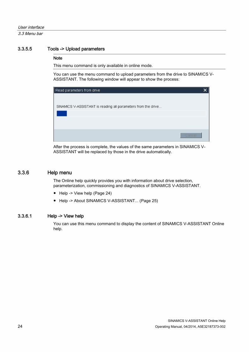
You can use the menu command to upload parameters from the drive to SINAMICS V-ASSISTANT. The following window will appear to show the process:
After the process is complete, the values of the same parameters in SINAMICS V-ASSISTANT will be replaced by those in the drive automatically.
3.3.6 Help menu The Online help quickly provides you with information about drive selection, parameterization, commissioning and diagnostics of SINAMICS V-ASSISTANT.
● Help -> View help (Page 24)
● Help -> About SINAMICS V-ASSISTANT... (Page 25)
3.3.6.1 Help -> View help You can use this menu command to display the content of SINAMICS V-ASSISTANT Online help.
User interface 3.4 Toolbar
SINAMICS V-ASSISTANT Online Help Operating Manual, 04/2014, A5E32187373-002 25
3.3.6.2 Help -> About SINAMICS V-ASSISTANT... You can use this menu command to display the following information window for SINAMICS V-ASSISTANT.
3.4 Toolbar The icons of the toolbar provide quick access to the commands in the menu bar or functions from Task navigation (Page 27).
New project (Page 15)
Open project (Page 16)
Save project (Page 17)
Print (Page 18)
Cut (Page 19)
Copy (Page 19)
Paste (Page 20)
Go offline (Page 20)
Go online (Page 20)
Save parameters to ROM (Page 21)
Viewing all parameters (Page 59)

User interface 3.5 Alarm window
SINAMICS V-ASSISTANT Online Help 26 Operating Manual, 04/2014, A5E32187373-002
Trace
Test motor (Page 71)
Help (Page 24)
3.5 Alarm window
Alarm window overview
① Alarm type: : Fault : Alarm
Faults have priority over alarms in display.
③ Alarm name and description
② Alarm number ④ Acknowledge All: Clears the faults in the buffer area of the drive
3.6 Function keys and shortcuts For frequently called functions, corresponding function keys and shortcuts are provided.
Function keys in SINAMICS V-ASSISTANT [F1] → Calls the context sensitive Online help [Ctrl+X] → Edit -> Cut (Page 19) [Ctrl+C] → Edit -> Copy (Page 19) [Ctrl+V] → Edit -> Paste (Page 20)

SINAMICS V-ASSISTANT Online Help Operating Manual, 04/2014, A5E32187373-002 27
Task navigation 4
Task Sub-functions Selecting drive (Page 28)
• Selecting drive (Page 29) • Selecting motor (Page 31) • Control mode (Page 32) • Jog (Page 34)
Parameterizing (Page 36)
• Setting electronic gear ratio (Page 37) • Setting mechanism (Page 39) • Setting parameter setpoint (Page 40) • Setting limits (Page 47) • Configuring inputs/outputs (Page 50) • Configuring referencing (Page 52) • Setting pulse train encoder output (Page 57) • Backlash compensation (Page 58) • Viewing all parameters (Page 59)

Task navigation
SINAMICS V-ASSISTANT Online Help 28 Operating Manual, 04/2014, A5E32187373-002
Task Sub-functions Commissioning (Page 61)
• Testing interface (Page 61) • Testing motor (Page 71) • Optimizing drive (Page 73)
Diagnostics (Page 78)
• Monitoring status (Page 78) • Tracing signals (Page 79) • Measuring machine (Page 83)
4.1 Selecting drive
① Drive selection Select a drive in this field.
For more information, refer to Section "Selecting drive (Page 29)".
② Motor selection Select a motor in this field. For more information, refer to Section "Selecting motor (Page 31)".
③ Control mode Select a control mode in this field. For more information, refer to Section "Control mode (Page 32)".
④ Jog Test the Jog function in this field. For more information, refer to Section "Jog (Page 34).
Task navigation
SINAMICS V-ASSISTANT Online Help Operating Manual, 04/2014, A5E32187373-002 29
4.1.1 Selecting drive
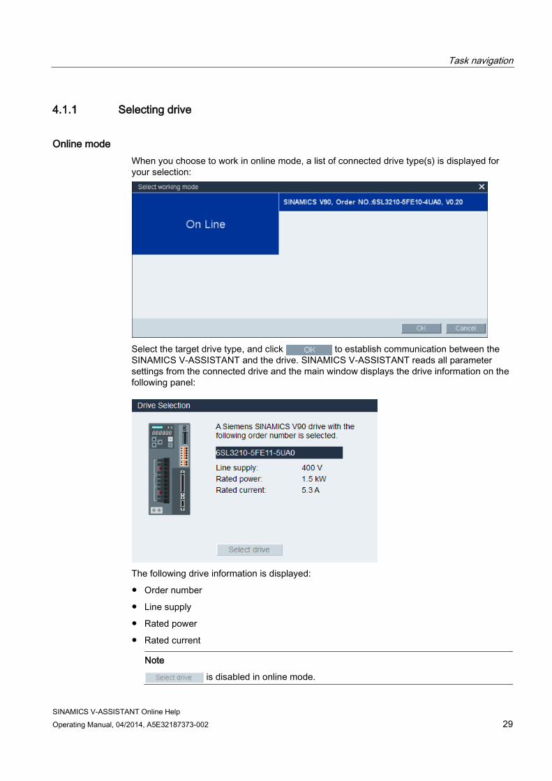
Online mode When you choose to work in online mode, a list of connected drive type(s) is displayed for your selection:
Select the target drive type, and click to establish communication between the SINAMICS V-ASSISTANT and the drive. SINAMICS V-ASSISTANT reads all parameter settings from the connected drive and the main window displays the drive information on the following panel:
The following drive information is displayed:
● Order number
● Line supply
● Rated power
● Rated current
Note
is disabled in online mode.

Task navigation
SINAMICS V-ASSISTANT Online Help 30 Operating Manual, 04/2014, A5E32187373-002
Offline mode When you are working in offline mode, the SINAMICS V-ASSISTANT does not communicate with the connected drive (s).
You can click to change the drive type in the following window:
Select the order number of the target drive. Click to save the factory settings of the selected drive to the new project and enter the main window; or otherwise, click
to cancel.
Task navigation
SINAMICS V-ASSISTANT Online Help Operating Manual, 04/2014, A5E32187373-002 31
4.1.2 Selecting motor
Online mode
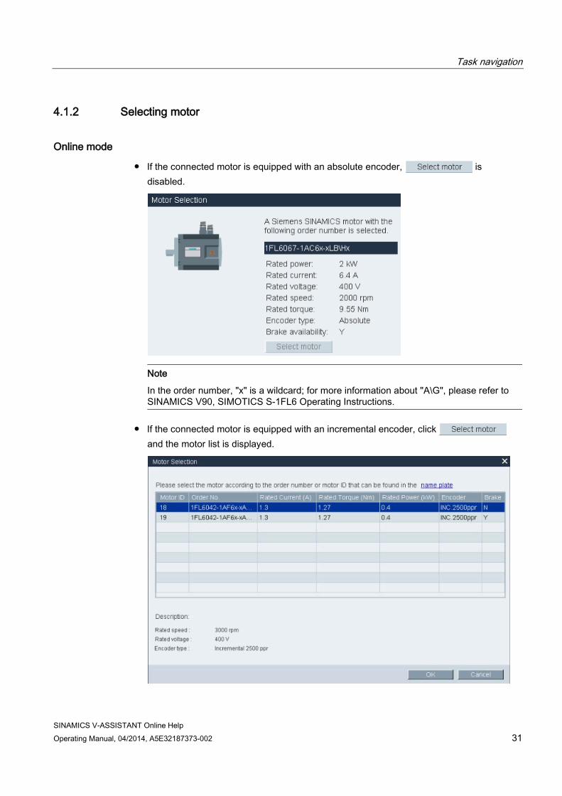
● If the connected motor is equipped with an absolute encoder, is disabled.
Note
In the order number, "x" is a wildcard; for more information about "A\G", please refer to SINAMICS V90, SIMOTICS S-1FL6 Operating Instructions.
● If the connected motor is equipped with an incremental encoder, click and the motor list is displayed.

Task navigation
SINAMICS V-ASSISTANT Online Help 32 Operating Manual, 04/2014, A5E32187373-002
Select a motor from the list and click the following button to confirm your selection:
Note
You can click "name plate" in the above window to see the specific location of the name plate on the motor.
Offline mode ● If you choose to create a new project, you need to select a drive first, then the information
of the default motor is displayed.
● If you choose to open an existing project, the saved motor information is displayed.
● If you switch from online mode to offline mode, you can select the motor by clicking .
4.1.3 Control mode
Online mode/offline mode
Totally, nine control modes are available:
Control modes Abbreviation Basic control modes Pulse train input position control mode (PTI) 1) PTI
Internal position control mode (IPos) IPos Speed control mode (S) S Torque control mode (T) T
Compound control modes
Control change mode: PTI/S PTI/S Control change mode: IPos/S IPos/S Control change mode: PTI/T PTI/T Control change mode: IPos/T IPos/T Control change mode: S/T S/T
1) Default control mode
Task navigation
SINAMICS V-ASSISTANT Online Help Operating Manual, 04/2014, A5E32187373-002 33
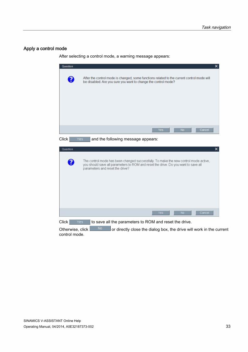
Apply a control mode After selecting a control mode, a warning message appears:
Click and the following message appears:
Click to save all the parameters to ROM and reset the drive.
Otherwise, click or directly close the dialog box, the drive will work in the current control mode.

Task navigation
SINAMICS V-ASSISTANT Online Help 34 Operating Manual, 04/2014, A5E32187373-002
4.1.4 Jog Jog function is only available in online mode. You can configure this function on the following panel:
● To start the Jog function, you can enter the Jog speed. Click , then the following warning will appear:
Click and run the drive counter-clockwisely/clockwisely by clicking the following two buttons respectively:
Then the actual speed, actual torque, actual current and actual utilization will be displayed.

Task navigation
SINAMICS V-ASSISTANT Online Help Operating Manual, 04/2014, A5E32187373-002 35
● To stop the Jog function, you can click in the following window and the SINAMICS V-ASSISTANT will release the control priority.
Note
The Jog speed should not be too fast. Otherwise, the machine axes will get out of control due to possible communication delay.

Task navigation
SINAMICS V-ASSISTANT Online Help 36 Operating Manual, 04/2014, A5E32187373-002
4.2 Parameterizing
Totally, there are nine functions. The sub-function combinations vary with the control modes:
Function Control mode
PTI IPos S T
Setting electronic gear ratio (Page 37)
✓
Setting mechanism (Page 39) ✓ Setting parameter setpoint (Page 40)
✓ ✓ ✓ ✓
Setting limits (Page 47) ✓ ✓ ✓ ✓ Configuring inputs/outputs (Page 50)
✓ ✓ ✓ ✓
Configuring referencing (Page 52)
✓
Setting pulse train encoder output (Page 57)
✓ ✓
Backlash compensation (Page 58)
✓ ✓
Viewing all parameters (Page 59)
✓ ✓ ✓ ✓
Task navigation
SINAMICS V-ASSISTANT Online Help Operating Manual, 04/2014, A5E32187373-002 37
4.2.1 Setting electronic gear ratio
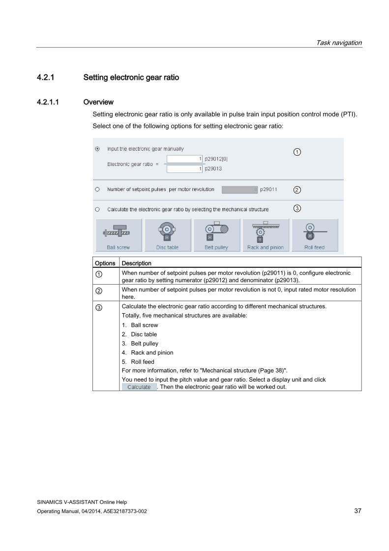
4.2.1.1 Overview Setting electronic gear ratio is only available in pulse train input position control mode (PTI).
Select one of the following options for setting electronic gear ratio:
Options Description
① When number of setpoint pulses per motor revolution (p29011) is 0, configure electronic gear ratio by setting numerator (p29012) and denominator (p29013).
② When number of setpoint pulses per motor revolution is not 0, input rated motor resolution here.
③ Calculate the electronic gear ratio according to different mechanical structures. Totally, five mechanical structures are available: 1. Ball screw 2. Disc table 3. Belt pulley 4. Rack and pinion 5. Roll feed For more information, refer to "Mechanical structure (Page 38)". You need to input the pitch value and gear ratio. Select a display unit and click
. Then the electronic gear ratio will be worked out.

Task navigation
SINAMICS V-ASSISTANT Online Help 38 Operating Manual, 04/2014, A5E32187373-002
4.2.1.2 Mechanical structure
Variables Configure variables according to the selected mechanical structure:
Mechanical structure
Graphical view Variable settings
Variable Range Ball screw
P: Pitch value (mm) 0.0001 to 2147000000
N: Load revolutions 1 to 2147000000 M: Motor revolutions 1 to 2147000000
Disc table
N: Load revolutions 1 to 2147000000 M: Motor revolutions 1 to 2147000000
Belt pulley
D: Diameter (mm)
0.0001 to 2147000000
N: Load revolutions 1 to 2147000000 M: Motor revolutions 1 to 2147000000
Rack and pinion
D: Diameter (mm)
0.0001 to 2147000000
N: Load revolutions 1 to 2147000000 M: Motor revolutions 1 to 2147000000
Roll feed
D: Diameter (mm)
0.0001 to 2147000000
N: Load revolutions 1 to 2147000000 M: Motor revolutions 1 to 2147000000
Unit After configuring the variables for the selected mechanical structure, you must select one of the following units and input values within the scope:
● Length unit
Range: 0.0001 to 2147000000
● Per one rotation of load axis
Range: 1 to 2147000000

Task navigation
SINAMICS V-ASSISTANT Online Help Operating Manual, 04/2014, A5E32187373-002 39
Calculation Click to calculate the electronic gear ratio and the calculated result is displayed as the following example:
Note
If either the numerator or the denominator of the electronic gear ratio is larger than 10000, the ratio will be reduced automatically to make them smaller than 10000.
4.2.2 Setting mechanism By parameterizing the mechanical system, the link between the physical moving part and the length unit (LU) is established. Select the mechanical structure. Set the gearbox factor and the length unit per revolution of the load on the following panel:

Task navigation
SINAMICS V-ASSISTANT Online Help 40 Operating Manual, 04/2014, A5E32187373-002
The unit of the fixed position setpoint is the Length Unit (LU). All subsequent position setpoint, related speed value, and acceleration value will maintain the LU as the unit in internal position control mode.
Taking a ball screw system for example, if the system has a pitch of 10 mm/revolution, the resolution of the length unit should be 1 µm (1 LU = 1 µm). Therefore, one load revolution corresponds to 10000 LU (p29247 = 10000).
4.2.3 Setting parameter setpoint Setting parameter setpoint is used to specify parameters related to speed, torque and position.
Depending on the current control mode, you can configure parameters of the sub-functions as follows:
Function Control mode
PTI IPos S T Signal form selection (Page 44)
✓
Position setpoint smoothing time setting (Page 44)
✓ ✓
Position reached window setting (Page 44)
✓ ✓
Fixed position setpoint (Page 44)
✓
Speed setpoint (Page 41) ✓ Ramp-function generator (Page 41)
✓
Speed reached window (Page 41)
✓
Torque setpoint (Page 41) ✓
In compound control modes, setting parameter setpoint can be referred to the single control mode.

Task navigation
SINAMICS V-ASSISTANT Online Help Operating Manual, 04/2014, A5E32187373-002 41
4.2.3.1 Torque setpoint
Source of torque setpoint Two sources are available for torque setpoint:
● External setpoint: analog input 2
● Fixed setpoint: p29043
These two resources can be selected with the digital input signal TSET:
Signal Level Source of torque setpoint TSET 0 (default) Analog torque setpoint (analog input 2)
1 Fixed torque setpoint (p29043)
4.2.3.2 Speed setpoint

Task navigation
SINAMICS V-ASSISTANT Online Help 42 Operating Manual, 04/2014, A5E32187373-002
Source of speed setpoint Eight sources in total are available for speed setpoint. You can select one of them with the combination of digital input signals SPD1, SPD2 and SPD3:
Digital signal Torque limit
SPD3 SPD2 SPD1 0 0 0 External analog speed setpoint (analog input 1) 0 0 1 Fixed speed setpoint 1 (p1001) 0 1 0 Fixed speed setpoint 2 (p1002) 0 1 1 Fixed speed setpoint 3 (p1003) 1 0 0 Fixed speed setpoint 4 (p1004) 1 0 1 Fixed speed setpoint 5 (p1005) 1 1 0 Fixed speed setpoint 6 (p1006) 1 1 1 Fixed speed setpoint 7 (p1007)
Ramp-function generator The ramp-function generator is used to limit acceleration in the event of abrupt setpoint changes and thus helps prevent load surges during drive operation.
The ramp-up time p1120 and ramp-down time p1121 can be used to set acceleration and deceleration ramps separately. This allows a smoothed transition in the event of setpoint changes.
Two types of ramp-function generator are available. You can specify the parameters on the corresponding panels:
● Basic ramp-function generator

Task navigation
SINAMICS V-ASSISTANT Online Help Operating Manual, 04/2014, A5E32187373-002 43
● Extended ramp-function generator
Speed reached window Set parameter p29078 for controller to decide whether the setpoint speed is reached on the following panel:

Task navigation
SINAMICS V-ASSISTANT Online Help 44 Operating Manual, 04/2014, A5E32187373-002
4.2.3.3 Position setpoint
Position setpoint ● In pulse train input position control mode, you can select one signal to link with pulse train
input from the following options:
Select the signal level on the following panel:
For detailed information, refer to the Section "Pulse train inputs (PTIs) (Page 71)".
● In internal position control mode, you must specify position setpoint on the following panel:
Linear axis or modular axis can be used depending on your actual application.
– The linear axis has a restricted traversing range and it is the factory setting of the SINAMICS V90 servo drive.
– The modular axis has an unrestricted traversing range.
You can directly enter the digital value in the cells for the following items:
– Position
– Speed

Task navigation
SINAMICS V-ASSISTANT Online Help Operating Manual, 04/2014, A5E32187373-002 45
– Acceleration
– Deceleration
The current active position setpoint channel is displayed at the bottom of this panel. The channels correspond with p2617 and p2618 as follows:
Position setpoint channel Index of p2617 Index of p2618 0 0 0 1 1 1 2 2 2 3 3 3 4 4 4 5 5 5 6 6 6 7 7 7
Source for internal position setpoint
Eight position setpoints in total are available. Each position setpoint comes from one group of position data:
Fixed position setpoint
Corresponding parameters Parameter Description
Fixed position setpoint 1
p2617[0] Fixed position setpoint 1 (P_pos1) 1) p2618[0] Speed of fixed position setpoint 1 (P_pos_spd1) 2) p2572 IPos maximum acceleration p2573 IPos maximum deceleration
Fixed position setpoint 2
p2617[1] Fixed position setpoint 2 (P_pos2) p2618[1] Speed of fixed position setpoint 2 (P_pos_spd2) p2572 IPos maximum acceleration p2573 IPos maximum deceleration
Fixed position setpoint 3
p2617[2] Fixed position setpoint 3 (P_pos3) p2618[2] Speed of fixed position setpoint 3 (P_pos_spd3) p2572 IPos maximum acceleration p2573 IPos maximum deceleration
Fixed position setpoint 4
p2617[3] Fixed position setpoint 4 (P_pos4) p2618[3] Speed of fixed position setpoint 4 (P_pos_spd4) p2572 IPos maximum acceleration p2573 IPos maximum deceleration
Fixed position setpoint 5
p2617[4] Fixed position setpoint 5 (P_pos5) p2618[4] Speed of fixed position setpoint 5 (P_pos_spd5) p2572 IPos maximum acceleration p2573 IPos maximum deceleration
Fixed position setpoint 6
p2617[5] Fixed position setpoint 6 (P_pos6) p2618[5] Speed of fixed position setpoint 6 (P_pos_spd6) p2572 IPos maximum acceleration

Task navigation
SINAMICS V-ASSISTANT Online Help 46 Operating Manual, 04/2014, A5E32187373-002
Fixed position setpoint
Corresponding parameters Parameter Description p2573 IPos maximum deceleration
Fixed position setpoint 7
p2617[6] Fixed position setpoint 7 (P_pos7) p2618[6] Speed of fixed position setpoint 7 (P_pos_spd7) p2572 IPos maximum acceleration p2573 IPos maximum deceleration
Fixed position setpoint 8
p2617[7] Fixed position setpoint 8 (P_pos8) p2618[7] Speed of fixed position setpoint 8 (P_pos_spd8) p2572 IPos maximum acceleration p2573 IPos maximum deceleration
Position setpoint smoothing time setting With the smoothing function, the position characteristics curve from the pulse train input setpoint can be transformed into an S-curve profile with a time constant specified in p2533.

Task navigation
SINAMICS V-ASSISTANT Online Help Operating Manual, 04/2014, A5E32187373-002 47
Position reached window setting Set parameter p2544 to specify the monitoring window for controller to decide whether the setpoint position is reached on the following panel:
Refer to Section "Digital outputs (DOs) (Page 67)" for more information about signal INP.
4.2.4 Setting limits You can configure speed limit, torque limit and software position limit with this function. The sub-functions vary with the selected control mode as follows:
Functions Control Mode
PTI IPos S T Torque limit (Page 48) ✓ ✓ ✓ Overall torque limit ✓ ✓ ✓ ✓ Speed limit (Page 49) ✓ ✓ ✓ ✓ Overall speed limit ✓ ✓ ✓ ✓ Software Position limit (Page 56)
✓

Task navigation
SINAMICS V-ASSISTANT Online Help 48 Operating Manual, 04/2014, A5E32187373-002
4.2.4.1 Torque limit Torque limit is available in control modes PTI, IPos and S.
You can specify the corresponding parameters on the following panel:
Source of torque limit Four sources in total are available for torque limit. You can select one of them via a combination of digital input signals TLIM1 and TLIM2:
Digital signal Torque limit
TLIM2 TLIM1 0 0 Internal torque limit 1 0 1 External torque limit (analog input 2) 1 0 Internal torque limit 2 1 1 Internal torque limit 3
When the torque setpoint reaches torque limit, the torque is limited to the value selected by TLIM1/TLIM2.
Note Control mode
These four sources are valid in the PTI mode, the IPos mode and the S mode. You can switch among them when the servo drive is running.
Refer to Section "Digital inputs (DIs) (Page 63)" for more information about the digital input signals TLIM1 and TLIM2.
Overall torque limit Besides the above four sources, an overall torque limit is available for all control modes. The overall torque limit takes effect when an emergency stop (OFF3) happens. In this case, the servo drive brakes with a maximum torque.

Task navigation
SINAMICS V-ASSISTANT Online Help Operating Manual, 04/2014, A5E32187373-002 49
4.2.4.2 Speed limit You can specify the corresponding parameters on the following panel:
Source of speed Limit Four sources in total are available for speed limit. You can select one of them via a combination of digital input signals SLIM1 and SLIM2:
Digital signal Speed limit
SLIM2 SLIM1 0 0 Internal speed limit 1 0 1 External speed limit (analog input 1) 1 0 Internal speed limit 2 1 1 Internal speed limit 3
Note Control mode
The above four sources are valid in all control modes. You can switch among them when the servo drive is running.
When the speed setpoint reaches the speed limit, an alarm occurs.
Refer to Section "Digital inputs (DIs) (Page 63)" for more information about the digital input signals SLIM1 and SLIM2.
Overall speed limit Besides the above four channels, an overall speed limit is available for all control modes.

Task navigation
SINAMICS V-ASSISTANT Online Help 50 Operating Manual, 04/2014, A5E32187373-002
4.2.5 Configuring inputs/outputs Three sub-functions are available as follows:
● Assigning digital inputs (Page 50)
● Assigning digital outputs (Page 51)
● Assigning analog outputs (Page 51)
4.2.5.1 Assigning digital inputs You can assign digital inputs on the following panel:
28 signals in total can be freely linked to digital inputs except for DI9 and DI10 linked with E_Stop and C_Mode signals, for more information, refer to Section "Digital inputs (DIs) (Page 63)".
Click the cells with white background in the table. Two options are displayed in the drop-down list: Assign and Cancel. Select "Assign" to link the digital input with the corresponding signal. Then the current row displays grey. Otherwise, select "Cancel" to release the link. The current row will then display white.
You can activate the checkbox in column "Set to 1" to forcely set the signal status to 1.
Note
Signal P_TRG in PTI mode is reserved for future use.

Task navigation
SINAMICS V-ASSISTANT Online Help Operating Manual, 04/2014, A5E32187373-002 51
4.2.5.2 Assigning digital outputs You can assign digital outputs on the following panel:
12 signals in total can be freely linked to digital outputs. For more information, refer to Digital outputs (DOs) (Page 67).
Click the cells with white background in the table. Select "Assign" to link the digital input with the corresponding signal. Then the current cell displays grey.
4.2.5.3 Assigning analog outputs You can assign analog outputs on the following panel:

Task navigation
SINAMICS V-ASSISTANT Online Help 52 Operating Manual, 04/2014, A5E32187373-002
Seven signals in total can be linked with either analog output. For more information, refer to Section "Analog outputs (AOs) (Page 70)".
By default, analog output 1and analog output 2 are linked with actual speed and actual torque respectively. You can freely select the target signal in the drop-down list to link with analog outputs.
4.2.6 Configuring referencing Referencing is only available in internal position control mode (IPos).
Two functions are available under referencing:
● Setting referencing (Page 52)
● Setting software position limit (Page 56)
4.2.6.1 Setting referencing Setting referencing is only available in online mode.
● Absolute encoder
If the motor is equipped with an absolute encoder, click on the folllowing panel to configure referencing:

Task navigation
SINAMICS V-ASSISTANT Online Help Operating Manual, 04/2014, A5E32187373-002 53
● Incremental encoder
If the motor is equipped with an incremental encoder, five referencing modes in total are available:
Parameter Value Referencing mode Illustration p29240 0 Setting the
reference point via digital input (signal REF)
1 External reference cam (signal REF) and encoder zero mark
Task navigation
SINAMICS V-ASSISTANT Online Help 54 Operating Manual, 04/2014, A5E32187373-002
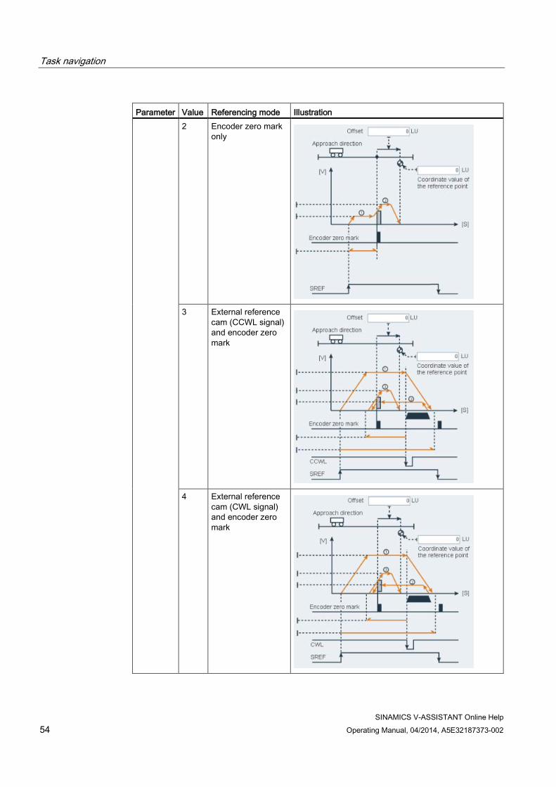
Parameter Value Referencing mode Illustration 2 Encoder zero mark
only
3 External reference cam (CCWL signal) and encoder zero mark
4 External reference cam (CWL signal) and encoder zero mark

Task navigation
SINAMICS V-ASSISTANT Online Help Operating Manual, 04/2014, A5E32187373-002 55
Taking the second referencing mode as an example, you can configure relevant parameters on the following panel:
Assign signals REF and SREF(for more information, refer to "Configuring inputs/outputs (Page 50)"). Click and the following warning appears:
Click to start referencing and the following window appears:
Click the button below to stop the referencing process.
Task navigation
SINAMICS V-ASSISTANT Online Help 56 Operating Manual, 04/2014, A5E32187373-002
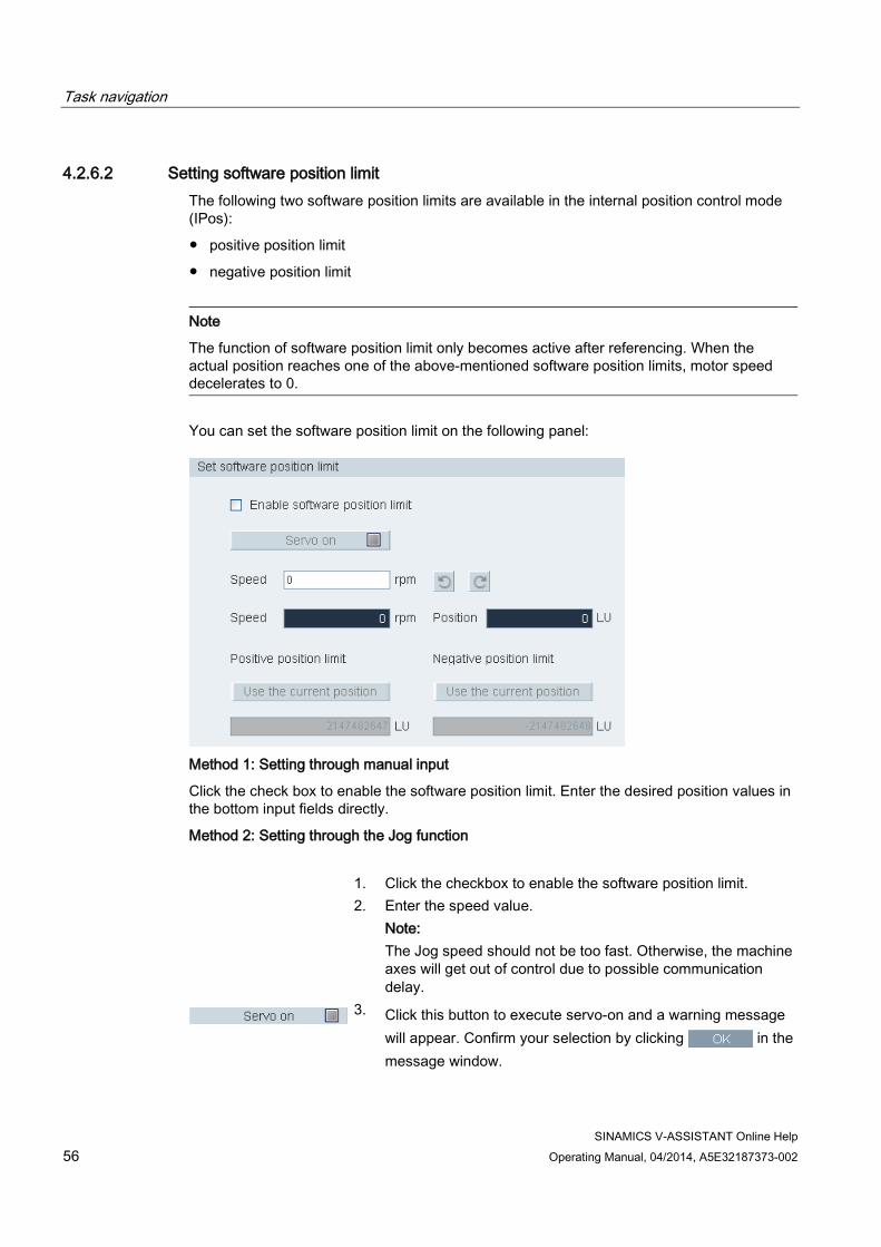
4.2.6.2 Setting software position limit The following two software position limits are available in the internal position control mode (IPos):
● positive position limit
● negative position limit
Note
The function of software position limit only becomes active after referencing. When the actual position reaches one of the above-mentioned software position limits, motor speed decelerates to 0.
You can set the software position limit on the following panel:
Method 1: Setting through manual input
Click the check box to enable the software position limit. Enter the desired position values in the bottom input fields directly.
Method 2: Setting through the Jog function
1. Click the checkbox to enable the software position limit. 2. Enter the speed value.
Note: The Jog speed should not be too fast. Otherwise, the machine axes will get out of control due to possible communication delay.
3. Click this button to execute servo-on and a warning message will appear. Confirm your selection by clicking in the message window.

Task navigation
SINAMICS V-ASSISTANT Online Help Operating Manual, 04/2014, A5E32187373-002 57
4. Click this button to rotate the motor clockwisely and the motor
will reach the maximum position.
5. Obtain the current position by clicking this button.
6. Click this button to rotate the motor counter-clockwisely and
the motor will reach the minimum position.
7. Obtain the current position by clicking this button.
8. If you desire to disable this function, you can click this button and the checkbox.
Note
Prerequisites for setting the software position limit: • Referencing is completed successfully • Linear axis working mode is selected
4.2.7 Setting pulse train encoder output When SINAMICS V-ASSISTANT is working in position control modes (PTI and IPos), you can configure pulse output on the following panel:
SINAMICS V-ASSISTANT automatically identifies the encoder type and resolution.
Two options are listed for you to configure relevant parameters:
● Set PTO number per revolution
● Set PTO number by gear ratio

Task navigation
SINAMICS V-ASSISTANT Online Help 58 Operating Manual, 04/2014, A5E32187373-002
4.2.8 Backlash compensation Generally, backlash occurs when the mechanical force is transferred between a machine part and its drive.
If the mechanical system was to be adjusted/designed so that there was absolutely no backlash, this would result in high wear. Thus, backlash can occur between the machine component and the encoder. For axes with indirect position sensing, mechanical backlash results in a false traversing distance because the axis, at direction reversal, travels either too far or not far enough corresponding to the absolute value of the backlash.
You can configure backlash compensation on the following panel:
In order to compensate the backlash, the determined backlash must be specified in p2583 with correct polarity. At each direction of rotation reversal, the axis actual value is corrected dependent on the actual traversing direction.
Note Pre-conditions for backlash compensation
The backlash compensation is active after • the axis has been referenced for incremental measuring system. Refer to Section "Setting
referencing (Page 52)" for detailed information about referencing. • the axis has been adjusted for absolute measuring system.

Task navigation
SINAMICS V-ASSISTANT Online Help Operating Manual, 04/2014, A5E32187373-002 59
4.2.9 Viewing all parameters You can configure all editable parameters in this field:

Task navigation
SINAMICS V-ASSISTANT Online Help 60 Operating Manual, 04/2014, A5E32187373-002
Field Description Group filter Views parameters according to different groups. Find Filters the parameter list according to the entered text. The filtering is done after you
enter the desired text. Factory default You can click to reset all parameters to their factory settings:
For more information, refer to Section "Tools -> Factory default (Page 22)". Save changes You can click to save the changes compared to the defaults/factory
settings into an .html file which can be further used for documentation purposes or as a reference for BOP commisioning. Save in the following window:
①: The default location is: xxx/Siemens/SINAMICS V-ASSISTANT/Project. xxx: SINAMICS V-ASSISTANT setup root directory
②: Only .html format is available. Table All parameters are displayed with the following information:
• Group • Parameter number • Name • Value • Unit • Range • Factory setting • Effect type Note: In the value related column, values with white background are editable.

Task navigation
SINAMICS V-ASSISTANT Online Help Operating Manual, 04/2014, A5E32187373-002 61
4.3 Commissioning
4.3.1 Testing interface
4.3.1.1 I/O simulation When SINAMICS V-ASSISTANT is working in online mode, you can configure I/O status on the following panel:

Task navigation
SINAMICS V-ASSISTANT Online Help 62 Operating Manual, 04/2014, A5E32187373-002
Area Item Description
① Pulse train input Information about pulse train input: • Received number of pulses. • Pulse frequency. For more information, refer to Section "Pulse train inputs (PTIs) (Page 71)".
② DI1~DI8 Every digital input can be linked with either of the 28 internal signals.
DI9 Linked with EMGS signal. DI10 Linked with C_MODE signal. Note: For more information about the number and definition of signals, refer to Section"Digital inputs (DIs) (Page 63)".
③ AI1 Linked with speed related signals. AI2 Linked with torque related signals. Note: For more information about analog inputs, refer to Section "Analog inputs (AIs) (Page 70)".
④ AO1 Linked with actual speed signal by default. AO2 Linked with actual torque signal by default. Note: For more information, refer to Section "Analog outputs (AOs) (Page 70)".
⑤ DO1~DO6 Every digital output can be freely linked with either of the 12 internal signals. For more information, refer to Section "Digital outputs (DOs) (Page 67)".
⑥ Clicking this button enables DO simulation. If you desire to disable this function, click the following button:
⑦
Signal is enabled Indicates high-voltage (or logic 1) is on the digital input/output.
Signal is disabled Indicates low-voltage (or logic 0) is on the digital input/output.
Signal is forcedly set to 1
Indicates the status of the assigned signal is forcedly set to 1.
Note • This function is unavailable but can be displayed in offline mode. • The status of each indicator and analog value are updated every 0.5 s. • Signal P_TRG in PTI mode is reserved for future use. • You can change the signal link as you desire. For more information, refer to Section
"Configuring inputs/outputs (Page 50)".

Task navigation
SINAMICS V-ASSISTANT Online Help Operating Manual, 04/2014, A5E32187373-002 63
4.3.1.2 Status of DI signals You can view the name, description, value and status of all the I/O signals on the following panel:
4.3.1.3 Digital inputs (DIs) You can assign a maximum of 28 internal digital input signals to the SINAMICS V90 servo drive. For detailed information about these signals, see the table below:
No. Name Type Description Control mode
PTI IPos S T 1 SON Edge
0→1 1→0
Servo-on • 0→1: powers on power circuit and makes
servo drive ready to operate. • 1→0: motor ramps down (OFF1) in PTI,
IPOS, and S modes; motor coasts down (OFF2) in T mode.
✓ ✓ ✓ ✓
2 RESET Edge 0→1
Reset alarms • 0→1: Reset alarms
✓ ✓ ✓ ✓
3 CWL Edge 1→0
Clockwise over-travel limit (positive limit) • 1 = condition for operation • 1→0: emergency stop (OFF3)
✓ ✓ ✓ ✓
4 CCWL Edge 1→0
Counter-clockwise over-travel limit (negative limit). • 1 = condition for operation • 1→0: emergency stop (OFF3)
✓ ✓ ✓ ✓

Task navigation
SINAMICS V-ASSISTANT Online Help 64 Operating Manual, 04/2014, A5E32187373-002
No. Name Type Description Control mode
PTI IPos S T 5 G-
CHANGE Level Gain change between the first and the
second gain parameter sets. • 0: the first gain parameter set • 1: the second gain parameter set
✓ ✓ ✓ X
6 P-TRG (P_TRG in PTI mode is reserved for future use)
Level Edge 0→1
In PTI mode: pulse allowable/inhibit. • 0: operation with pulse train setpoint is
possible • 1: inhibit the pulse train setpoint In IPos mode: position trigger • 0→1: starts positioning of selected fixed
position setpoint
✓ ✓ X X
7 CLR Level Clear position control droop pulses. • 0: no clearing • 1: always clear
✓ X X X
8 EGEAR1 Level Electronic gear. A combination of the signals EGEAR1 and EGEAR2 can select four electronic gear ratios. EGEAR2 : EGEAR1 • 0 : 0: electronic gear ratios 1 • 0 : 1: electronic gear ratios 2 • 1 : 0: electronic gear ratios 3 • 1 : 1: electronic gear ratios 4
✓ ✓ X X 9 EGEAR2 Level ✓ ✓ X X
10 TLIM1 Level Torque limit selection. A combination of TLIM1 and TLIM2 can select four torque limit sources (one external torque limit, three internal torque limits). TLIM2 : TLIM1 • 0 : 0: internal torque limit 1 • 0 : 1: external torque limit (Analog Input
2) • 1 : 0: internal torque limit 2 • 1 : 1: internal torque limit 3
✓ ✓ ✓ X 11 TLIM2 Level
12 CWE Level Enable clockwise rotations. • 1: Enable clockwise rotation, ramp up • 0: Disable clockwise rotation, ramp down
X X ✓ ✓
13 CCWE Level Enable counter-clockwise rotations. • 1: Enable counter-clockwise rotation,
ramp down • 0: Disable counter-clockwise rotation,
ramp up
X X ✓ ✓

Task navigation
SINAMICS V-ASSISTANT Online Help Operating Manual, 04/2014, A5E32187373-002 65
No. Name Type Description Control mode
PTI IPos S T 14 ZSCLAM
P Level Zero speed clamps.
• 1 = when the motor speed setpoint is an analog signal and lower than the threshold level (P_zclamp_threshold), the motor is clamped.
• 0 = no action
X X ✓ X
15 SPD1 Level Select speed mode: fixed speed setpoint. A combination of the signals SPD1, SPD2 and SPD3 can select eight speed setpoint sources (one external speed setpoint, seven fixed speed setpoint). SPD3 : SPD2 : SPD1 • 0 : 0 : 0: external analog speed setpoint • 0 : 0 : 1: fixed speed setpoint 1 • 0 : 1 : 0: fixed speed setpoint 2 • 0 : 1 : 1: fixed speed setpoint 3 • 1 : 0 : 0: fixed speed setpoint 4 • 1 : 0 : 1: fixed speed setpoint 5 • 1 : 1 : 0: fixed speed setpoint 6 • 1 : 1 : 1: fixed speed setpoint 7
X X ✓ X 16 SPD2 Level 17 SPD3 Level
18 TSET Level Torque setpoint selection. This signal can select two torque setpoint sources (one external torque setpoint, one fixed torque setpoint). • 0: external torque setpoint (Analog Input
2) • 1: fixed torque setpoint
X X X ✓
19 SLIM1 Level Speed limit selection. A combination of SLIM1 to SLIM2 can select four speed limit sources (one external speed limit, three internal speed limits). SLIM2 : SLIM1 • 0 : 0: internal speed limit 1 • 0 : 1: external speed limit (Analog Input
1) • 1 : 0: internal speed limit 2 • 1 : 1: internal speed limit 2
✓ ✓ ✓ ✓ 20 SLIM2 Level
21 POS1 Level Select position setpoint. A combination of the signals POS1 to POS3
X ✓ X X 22 POS2 Level

Task navigation
SINAMICS V-ASSISTANT Online Help 66 Operating Manual, 04/2014, A5E32187373-002
No. Name Type Description Control mode
PTI IPos S T 23 POS3 Level can select eight fixed position setpoint
sources. POS3 : POS2 : POS1 • 0 : 0 : 0: fixed position setpoint 1 • 0 : 0 : 1: fixed position setpoint 2 • 0 : 1 : 0: fixed position setpoint 3 • 0 : 1 : 1: fixed position setpoint 4 • 1 : 0 : 0: fixed position setpoint 5 • 1 : 0 : 1: fixed position setpoint 6 • 1 : 1 : 0: fixed position setpoint 7 • 1 : 1 : 1: fixed position setpoint 8
24 REF Edge 0→1
Set reference point with digital input or reference cam input for reference approaching mode. • 0→1: reference input
X ✓ X X
25 SREF Edge 0→1
The reference approach will be started with the signal SREF. • 0→1 start reference approach
X ✓ X X
26 STEPF Edge 0→1
Step forward to the next fixed position setpoint. • 0→1 start step action
X ✓ X X
27 STEPB Edge 0→1
Step backward to the previous fixed position setpoint. • 0→1 start step action
X ✓ X X
28 STEPH Edge 0→1
Step to the fixed position setpoint 1. • 0→1 start step action
X ✓ X X
Note
When working in the torque control mode, the torque setpoint equals to 0 if CWE and CCWE are at the same status. For more information, please refer to SINAMICS V90, SIMOTICS S-1FL6 Operating Instructions.
Note Invalid circumstances for DI signals • All DI signals except for EMGS are invalid during parameter saving. • All DI signals except for CWL, CCWL, and EMGS are invalid during auto tuning. • When SINAMICS V-ASSISTANT is communicating with the drive or you are operating the
drive on SINAMICS V-ASSISTANT, some DI signals are invalid: – When referencing by SINAMICS V-ASSISTANT, the DI signal SREF is invalid. – During trial run test, the DI signal SON is invalid; meanwhile, DI7 and DI8 are
occupied by SINAMICS V-ASSISTANT.

Task navigation
SINAMICS V-ASSISTANT Online Help Operating Manual, 04/2014, A5E32187373-002 67
Direct signal map Force the following six signals to logical "1" signals with parameter p29300 (P_DI_Mat):
● SON
● CWL
● CCWL
● TLIM1
● SPD1
● TSET
The definition for p29300 is as follows:
Bit 5 Bit 4 Bit 3 Bit 2 Bit 1 Bit 0 TSET SPD1 TLIM1 CCWL CWL SON
For example, if you set p29300 = 1 to force SON to a logical high signal, DI1 can then be assigned to other desired signals.
Note
The parameter p29300 has higher priority than the DIs.
4.3.1.4 Digital outputs (DOs) You can assign a maximum of 13 internal digital output signals to the SINAMICS V90 servo drive. For detailed information about these signals, see the table below:
No. Name Descriptions Control mode
PTI IPos S T 1 RDY Servo ready
• 1: ready to operate • 0: drive not ready (alarm occurs or enable
signal is missing)
✓ ✓ ✓ ✓
2 ALM Alarm • 1: in alarm status • 0: no alarm
✓ ✓ ✓ ✓
3 INP In-position signal • 1: number of droop pulses is in the preset in-
position range (parameter p2544) • 0: droop pulses are beyond the in-position
range
✓ ✓ X X

Task navigation
SINAMICS V-ASSISTANT Online Help 68 Operating Manual, 04/2014, A5E32187373-002
No. Name Descriptions Control mode
PTI IPos S T 4 ZSP Zero speed detection
• 1: motor speed is equal with or lower than the zero speed (can be set with parameter P_z_spd).
• 0: motor speed is higher than zero speed + hysteresis (10 rpm).
✓ ✓ ✓ ✓
5 SPDR Speed reached • 1: motor actual speed has nearly (internal
hysteresis 10 rpm) reached the speed of the internal speed command or analog speed command. The speed approaching range can be set via parameter p29078
• 0: speed difference between speed setpoint and actual is larger than internal hysteresis.
X X ✓ X
6 TLR Torque limit reached • 1: the generated torque has nearly (internal
hysteresis) reached the value of the positive torque limit, negative torque limit or analog torque limit
• 0: the generated torque has not reached the limit
X X ✓ X
7 SPLR Speed limit reached • 1: the speed has nearly (internal hysteresis,
10 rpm) reached the speed limit. • 0: the speed has not reached the speed
limit.
✓ ✓ ✓ X
8 MBR Motor holding brake • 1: motor holding brake is closed • 0: motor holding brake is released Note: MBR is only status signal because the control and the power supply of the motor holding brake is realized with separate terminals.
✓ ✓ ✓ ✓
9 OLL Overload level reached • 1: motor has reached the parameterizable
output overload level (P_overload_level in % of rated torque, default: 100%, max: 300%)
• 0: motor has not reached the overload level
✓ ✓ ✓ ✓
Task navigation
SINAMICS V-ASSISTANT Online Help Operating Manual, 04/2014, A5E32187373-002 69
No. Name Descriptions Control mode
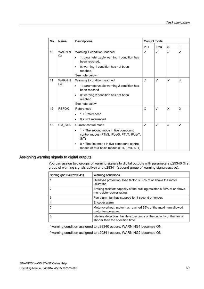
PTI IPos S T 10 WARNIN
G1 Warning 1 condition reached • 1: parameterizable warning 1 condition has
been reached. • 0: warning 1 condition has not been
reached. See note below.
✓ ✓ ✓ ✓
11 WARNING2
Warning 2 condition reached • 1: parameterizable warning 2 condition has
been reached • 0: warning 2 condition has not been
reached. See note below
✓ ✓ ✓ ✓
12 REFOK Referenced • 1 = Referenced • 0 = Not referenced
X ✓ X X
13 CM_STA Current control mode • 1 = The second mode in five compound
control modes (PTI/S, IPos/S, PTI/T, IPos/T, S/T)
• 0 = The first mode in five compound control modes or four basic modes (PTI, IPos, S, T)
✓ ✓ ✓ ✓
Assigning warning signals to digital outputs You can assign two groups of warning signals to digital outputs with parameters p29340 (first group of warning signals active) and p29341 (second group of warning signals active).
Setting (p29340/p29341) Warning conditions 1 Overload protection: load factor is 85% of or above the motor
utilization. 2 Braking resistor: capacity of the braking resistor is 85% of or above
the resistor power rating. 3 Fan alarm: fan has stopped for 1 second or longer. 4 Encoder alarm 5 Motor overheat: motor has reached 85% of the maximum allowed
motor temperature. 6 Lifetime detection: the life expectancy of the capacity or the fan is
shorter than the specified time.
If warning condition assigned to p29340 occurs, WARNING1 becomes ON.
If warning condition assigned to p29341 occurs, WARNING2 becomes ON.

Task navigation
SINAMICS V-ASSISTANT Online Help 70 Operating Manual, 04/2014, A5E32187373-002
4.3.1.5 Analog inputs (AIs) Two analog inputs in total are available:
● AI1: linked with speed related signals.
● AI2: linked with torque related signals.
In different control modes, the analog inputs are linked with different signals:
Control mode AI1 AI2 Position (PTI and IPos) Not used Torque limitation S Speed setpoint Torque limitation T Speed limitation Torque setpoint PTI/S and IPos/S Not used in position control
modes --> Speed setpoint in S mode
Torque limitation
PTI/T and IPos/T Not used in position control modes -->Speed limitation in T mode
Torque limitation in position control modes --> Torque setpoint in T mode
S/T Speed setpoint in S mode --> Speed limitation in T mode
Torque limitation in S mode --> Torque setpoint in T mode
4.3.1.6 Analog outputs (AOs) Two parameters, p29350 (selects signal sources for AO1) and p29351 (selects signal sources for AO2), are used to select the source of analog output:
Parameter Value Source Value Source
p29350 0 (default)
Actual speed (reference p29060)
7 Pulse input frequency (reference 100 k)
1 Actual torque (reference 3 × r0333)
8 Pulse input frequency (reference 1000 k)
2 Speed setpoint (reference p29060)
9 Remaining number of pulses (reference 1 k)
3 Torque setpoint (reference 3 × r0333)
10 Remaining number of pulses (reference 10 k)
4 DC bus voltage (reference 1000 V)
11 Remaining number of pulses (reference 100 k)
5 Pulse input frequency (reference 1 k)
12 Remaining number of pulses (reference 1000 k)
6 Pulse input frequency (reference 10 k)
p29351 0 Actual speed (reference p29060)
7 Pulse input frequency (reference 100 k)
1 (default)
Actual torque (reference 3 × r0333)
8 Pulse input frequency (reference 1000 k)
2 Speed setpoint (reference p29060)
9 Remaining number of pulses (reference 1 k)

Task navigation
SINAMICS V-ASSISTANT Online Help Operating Manual, 04/2014, A5E32187373-002 71
Parameter Value Source Value Source 3 Torque setpoint (reference 3 ×
r0333) 10 Remaining number of pulses
(reference 10 k) 4 DC bus voltage (reference
1000 V) 11 Remaining number of pulses
(reference 100 k) 5 Pulse input frequency
(reference 1 k) 12 Remaining number of pulses
(reference 1000 k) 6 Pulse input frequency
(reference 10 k)
4.3.1.7 Pulse train inputs (PTIs) The SINAMICS V90 servo drive supports two kinds of setpoint pulse train input forms:
● AB track pulse
● Pulse + Direction
For both forms, positive logic and negative logic are supported:
Pulse train input form
Positive logic = 0 Negative logic = 1
Forward (CW) Reverse (CCW) Forward (CCW) Reverse (CW) AB track pulse
Pulse + Direction
4.3.1.8 Pulse train encoder outputs (PTOs)
Function A pulse train encoder output (PTO) which provides pulse signals can transmit the signals to the controller to realize a closed-loop control system inside the controller, or transmit them to another drive as pulse train setpoint for a synchronous axis.
4.3.2 Testing motor Two sub-functions are available:
● Jog (Page 72)
● Position trial run (Page 72)

Task navigation
SINAMICS V-ASSISTANT Online Help 72 Operating Manual, 04/2014, A5E32187373-002
4.3.2.1 Jog For detailed information about Jog function, refer to Section "Jog (Page 34)".
4.3.2.2 Position trial run In online mode, you can configure this function on the following panel:
Note
Position trial run is only available in position control modes (PTI and IPos).

Task navigation
SINAMICS V-ASSISTANT Online Help Operating Manual, 04/2014, A5E32187373-002 73
Operating sequence 1. Enter the Jog speed.
2. Use this button to enable the Jog function. Note: After clicking this button, a warning message will appear. Click
in the message window to confirm executing servo-on.
3. Click this button to rotate the motor clockwisely and the motor
will reach the maximum position.
4. Obtain the maximum position by clicking this button on the right of the panel.
5. Click this button to rotate the motor counter-clockwisely and
the motor will reach the minimum position.
6. Obtain the minimum position by clicking this button on the left of the panel. Note: Make sure the actual position is within the scope. Otherwise, the position trial run cannot be started.
7. Use this button to disable the Jog function. Note: The Jog function must be disabled before position trial run is started.
8. Enter the moving distance and moving speed.
9. Start trial run by clicking this button. Or otherwise, click the following button to stop trial run:
10. If necessary, click this button to move back to the previous position.
4.3.3 Optimizing drive You can select the desired tuning mode from the drop-down list on the following panel:

Task navigation
SINAMICS V-ASSISTANT Online Help 74 Operating Manual, 04/2014, A5E32187373-002
4.3.3.1 Manual tuning When the auto tuning cannot reach the expected tuning results, you can disable the auto tuning function by setting the parameter p29021 and manually perform tuning:
● p29021=5: auto tuning function is disabled and all control parameters (servo gains) are reset to default values.
● p29021=0: auto tuning function is disabled without changing control parameters (servo gains).
Parameter settings You can set the parameters on the following panel:
Click to reset the following parameters of gain setting to their defaults:
● p29110[0]
● p29111
● p29120[0]
● p29121[0]
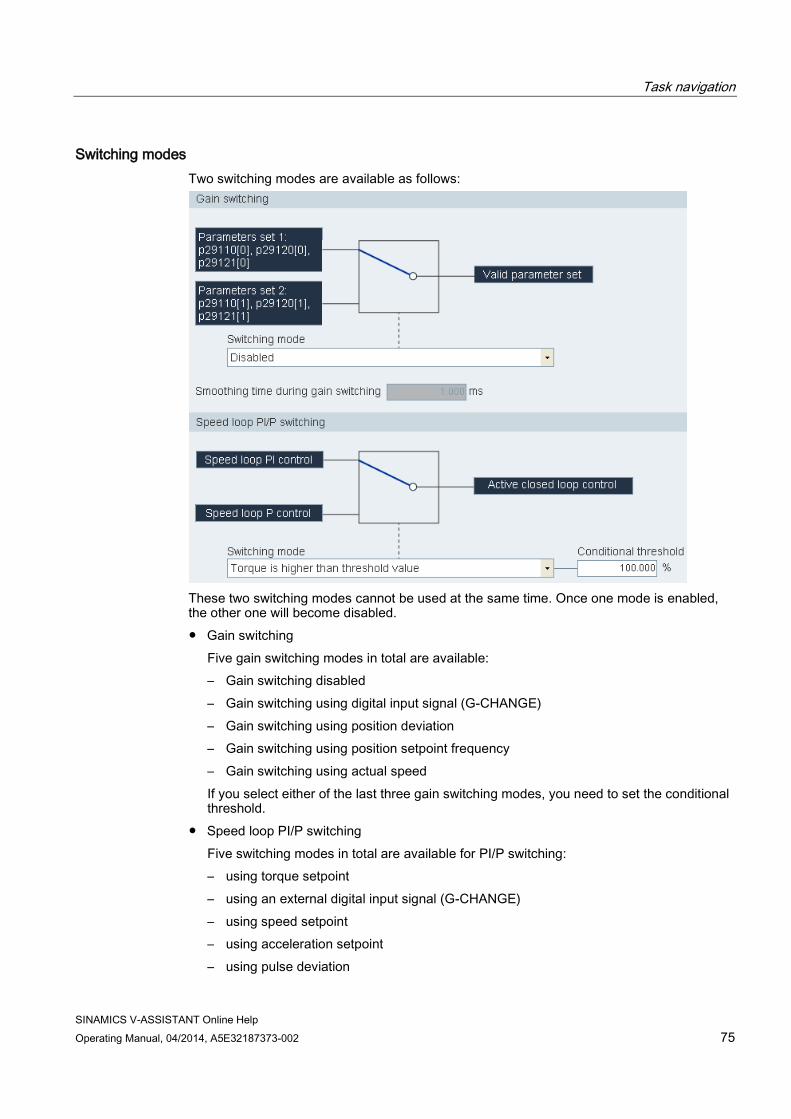
Task navigation
SINAMICS V-ASSISTANT Online Help Operating Manual, 04/2014, A5E32187373-002 75
Switching modes Two switching modes are available as follows:
These two switching modes cannot be used at the same time. Once one mode is enabled, the other one will become disabled. ● Gain switching
Five gain switching modes in total are available: – Gain switching disabled – Gain switching using digital input signal (G-CHANGE) – Gain switching using position deviation – Gain switching using position setpoint frequency – Gain switching using actual speed If you select either of the last three gain switching modes, you need to set the conditional threshold.
● Speed loop PI/P switching Five switching modes in total are available for PI/P switching: – using torque setpoint – using an external digital input signal (G-CHANGE) – using speed setpoint – using acceleration setpoint – using pulse deviation
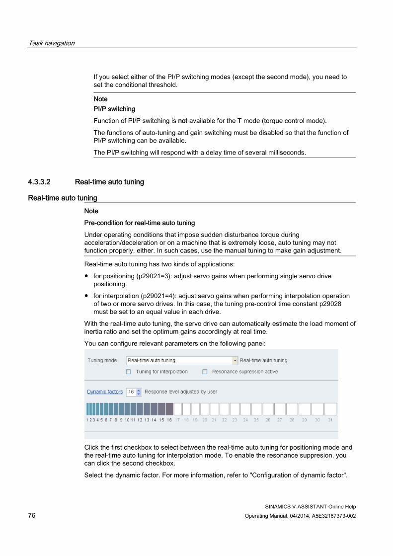
Task navigation
SINAMICS V-ASSISTANT Online Help 76 Operating Manual, 04/2014, A5E32187373-002
If you select either of the PI/P switching modes (except the second mode), you need to set the conditional threshold.
Note
PI/P switching
Function of PI/P switching is not available for the T mode (torque control mode).
The functions of auto-tuning and gain switching must be disabled so that the function of PI/P switching can be available.
The PI/P switching will respond with a delay time of several milliseconds.
4.3.3.2 Real-time auto tuning
Real-time auto tuning
Note
Pre-condition for real-time auto tuning
Under operating conditions that impose sudden disturbance torque during acceleration/deceleration or on a machine that is extremely loose, auto tuning may not function properly, either. In such cases, use the manual tuning to make gain adjustment.
Real-time auto tuning has two kinds of applications:
● for positioning (p29021=3): adjust servo gains when performing single servo drive positioning.
● for interpolation (p29021=4): adjust servo gains when performing interpolation operation of two or more servo drives. In this case, the tuning pre-control time constant p29028 must be set to an equal value in each drive.
With the real-time auto tuning, the servo drive can automatically estimate the load moment of inertia ratio and set the optimum gains accordingly at real time.
You can configure relevant parameters on the following panel:
Click the first checkbox to select between the real-time auto tuning for positioning mode and the real-time auto tuning for interpolation mode. To enable the resonance suppresion, you can click the second checkbox.
Select the dynamic factor. For more information, refer to "Configuration of dynamic factor".

Task navigation
SINAMICS V-ASSISTANT Online Help Operating Manual, 04/2014, A5E32187373-002 77
Resonance suppression The resonance suppression function is filter (notch filter) function. It detects mechanical resonance at a frequency between 250 Hz and 1000 Hz, and decreases the gain of specific frequency (by automatically setting notch filter) to suppress the mechanical resonance.
Selecting a resonance suppression mode:
Three modes are available for this function. You can select one of them by setting the parameter p29023:
Parameter
Value range Value Unit Description
p29023 0 to 2 0 - Resonance suppression mode: • 0: resonance suppression deactivated (manual
input of resonance frequency) • 1: real-time resonance suppression • 2: one-time resonance frequency search with
excitation
On the user interface of SINAMICS V-ASSISTANT, only the first two suppresion modes are available. You can click the second checkbox on the above panel to select between these two modes. If you desire to use the third suppresion mode, you can proceed through changing the value of parameter p29023. For more information, refer to Section "Viewing all parameters (Page 59)".

Task navigation
SINAMICS V-ASSISTANT Online Help 78 Operating Manual, 04/2014, A5E32187373-002
4.4 Diagnostics
4.4.1 Monitoring status
Note
This function can only work in online mode.
You can monitor the real-time value of motion related parameters. The motion data and product information are displayed on the following panel:

Task navigation
SINAMICS V-ASSISTANT Online Help Operating Manual, 04/2014, A5E32187373-002 79
4.4.2 Tracing signals With this function, you can trace the performance of the connected drive in the current control mode on the following panel:
Area Item Description
① Trace configuration
Opens the window of trace configuration. For more information, refer to "Trace configuration (Page 81)".
Start/stop trace (Only available in online mode)
Starts recording the current trace. If you desire to stop the trace process, click the following button:
② Cursors By default, the cursor displays as a cross in the diagram. You can select an area of the diagram for detailed view by left-clicking and holding your mouse.
Changes the cursor shape from cross to arrow. When the cursor displays as an arrow, you can directly select a curve and use it for variable calculation. Note: The selected curve displays highlighted.
If you click this button, you can move the selected curve freely after the cursor appears in the shape of a hand.
Auxiliary lines
Vertical cursor: Displays coordinates t1 and t2 in the diagram. You can move t1or t2 when the cursor displays as .

Task navigation
SINAMICS V-ASSISTANT Online Help 80 Operating Manual, 04/2014, A5E32187373-002
Area Item Description
Horizontal cursor: • In time domain diagram, you can click this button to
display coordinates y1 and y2 in the diagram. You can move y1 or y2 when the cursor displays as .
• In frequency domain diagram, activate this button to display a highlighted coordinate in the diagram. You can move this coordinate in the diagram when the cursor displays as .
Zoom
Zooms in the current curves with a specified scale.
Zooms out the current curves with a specified scale.
Restores curves in the diagram.
File operation
Opens an existing .trc file for curve display in the diagram.
Saves the current recording of values as a .trc file.
Note: In frequency domain diagram, all the above tools are unavailable except the horizontal cursor.
③ Diagrams • Time domain diagram:
Displays the time diagram in curves and records measured values of parameters.
• Frequency domain diagram:
Available for mathematically computed curves and displays the Fourier transformation.
④ Time domain diagram T Coordinate T (time):
• t1: Real-time value of coordinate t1 • t2: Real-time value of coordinate t2 • dt: Automatically calculated duration.
The formula is as follows:
dt = t2 - t1 Y Coordinate Y:
• y1: Real-time value of coordinate y1 • y2: Real-time value of coordinate y2 • dy: Automatically calculated value range.
The formula is as follows:
dy = y2 - y1

Task navigation
SINAMICS V-ASSISTANT Online Help Operating Manual, 04/2014, A5E32187373-002 81
Area Item Description
Y(T) • y(t1): Real-time value at the cross point of coordinate t1 and selected curve.
• y(t2): Real-time value at the cross point of coordinate t2 and selected curve.
• dy(t): Automatically calculated real-time value range.
The formula is as follows:
dy(t) = y(t2) - y(t1) Note: You can select a coordinate by clicking its designation, then the selected coordinate displays yellow. Frequency domain diagram Frequency Displays real-time frequency value of the horizontal
cursor coordinate in the diagram. Amplitude Displays real-time amplitude value at the cross point of
the horizontal cursor coordinate and curve. ⑤ Curve selection Selects a curve to display in the diagram.
• Time domain diagram:
A maximum of six curves can be simultaneously displayed in the diagram.
• Frequency domain diagram:
Only one curve can be selected to display in the diagram.
4.4.2.1 Trace configuration

Task navigation
SINAMICS V-ASSISTANT Online Help 82 Operating Manual, 04/2014, A5E32187373-002
Index Function description
① Click the following button to select the analog signal.
Select a trace signal and click to confirm your selection. Or otherwise, you can click to cancel. Click the color bar to define the display color of the curve for the signal.
② Click the following button to select the digital signal.
Select a trace signal and click to confirm your selection. Or otherwise, you can click to cancel. Click the color bar to define the display color of the curve for the signal.
③ Recording settings: You can select the factor and define the trace cycle clock, maximum duration and recording duration.
④ Seven trigger types are available for your selection: • Immediate recording (default settings) • Trigger on rising edge
Note:
The digital signals must be set to 1. Otherwise, the rising edge cannot be triggered.
• Trigger on falling edge
Note:
The digital signals must be set to 0. Otherwise, the falling edge cannot be triggered.
• Trigger within the scope • Trigger outside of the scope • Trigger at alarm • Trigger at fault
Trigger type settings: • For the last six trigger types, you can select pre-trigger or post-trigger and the
trigger signal. • For the fourth and fifth trigger types, you can enter the threshold upper/lower
value in the textbox.

Task navigation
SINAMICS V-ASSISTANT Online Help Operating Manual, 04/2014, A5E32187373-002 83
4.4.3 Measuring machine The measuring function is used for controller optimization. With measuring function, you can directly inhibit the influence of higher-level control loops by means of simple parameterization, and analyze the dynamic response of individual drives.
For easier handling of the controller optimization, predefined measuring functions are available for selection. The operating mode is automatically set depending on the measuring function.
● Speed controller setpoint frequency response(before speed setpoint filter)
The speed control loop is closed while all of the higher-level control loops are open. For the setpoint frequency response on the speed controller, the speed setpoint is activated by a PRBS signal. The evaluation of the signals is performed in the frequency range.
● Speed control system(excitation after current setpoint filter)
The speed control loop is closed while all of the higher-level control loops are open. For the measurement of the speed controller system on the speed controller, the speed setpoint is activated by a PRBS signal. The evaluation of the signals is performed in the frequency range.
● Current controller setpoint frequency response(after current setpoint filter)
For the reference frequency response on the current controller, the current setpoint is activated by a PRBS signal. The evaluation of the signals is performed in the frequency range.
Note
Measuring machine is only available in online mode.
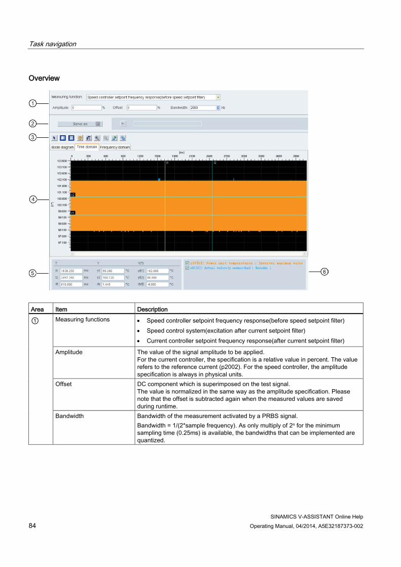
Task navigation
SINAMICS V-ASSISTANT Online Help 84 Operating Manual, 04/2014, A5E32187373-002
Overview
Area Item Description
① Measuring functions • Speed controller setpoint frequency response(before speed setpoint filter) • Speed control system(excitation after current setpoint filter) • Current controller setpoint frequency response(after current setpoint filter)
Amplitude The value of the signal amplitude to be applied. For the current controller, the specification is a relative value in percent. The value refers to the reference current (p2002). For the speed controller, the amplitude specification is always in physical units.
Offset DC component which is superimposed on the test signal. The value is normalized in the same way as the amplitude specification. Please note that the offset is subtracted again when the measured values are saved during runtime.
Bandwidth Bandwidth of the measurement activated by a PRBS signal. Bandwidth = 1/(2*sample frequency). As only multiply of 2n for the minimum sampling time (0.25ms) is available, the bandwidths that can be implemented are quantized.

Task navigation
SINAMICS V-ASSISTANT Online Help Operating Manual, 04/2014, A5E32187373-002 85
Area Item Description
② Servo on/off Click and the following warning appears:
Confirm by clicking to obtain the control priority for the connected drive.
Then becomes . If you desire to give up the control priority, you can directly click it.
Start trace
Click this button to start trace. Note: During the trace process, you cannot stop it but only wait until it is complete.
③ Cursor By default, the cursor displays as a cross in the diagram. You can select an area of the diagram for detailed view by left-clicking and holding your mouse.
Changes the cursor shape from cross to arrow. When the cursor displays as an arrow, you can directly select a curve and use it for variable calculation. Note: The selected curve displays highlighted.
If you click this button, you can move the selected curve freely after the cursor appears in the shape of a hand.
Auxiliary line
Vertical cursor:
Displays coordinates t1 and t2 in the diagram. You can move t1or t2 when the
cursor displays .
Horizontal cursor:
• In time domain diagram, you can click this button to display coordinates y1 and
y2 in the diagram. You can move y1 or y2 when the cursor displays .
• In frequency domain diagram, activate this button to display a highlighted
coordinate in the diagram. You can move this coordinate in the diagram when
the cursor displays .
Zoom
Zooms in the current curves with a specified scale.
Zooms out the current curves with a specified scale.
Restores curves in the diagram.
File operation
Opens an existing .trc file for curve display in the diagram.

Task navigation
SINAMICS V-ASSISTANT Online Help 86 Operating Manual, 04/2014, A5E32187373-002
Area Item Description
Saves the current recording of values as a .trc file.
Note: In frequency domain diagram, all the above tools are unavailable except the horizontal cursor.
④
Diagram • Time domain diagram:
Displays the time diagram in curves and records measured values of parameters.
• Frequency domain diagram:
Available for mathematically computed curves and displays the Fourier transformation.
• Bode domain diagram:
Available for mathematically computed curves. ⑤ Time domain diagram
T Coordinate T (time): • t1: Real-time value of coordinate t1 • t2: Real-time value of coordinate t2 • dt: Automatically calculated duration The calculation formula is as follows: dt = t2 - t1
Y Coordinate Y: • y1: Real-time value of coordinate y1 • y2: Real-time value of coordinate y2 • dy: Automatically calculated value range The calculation formula is as follows: dy = y2 - y1
Y(T) • y(t1): Real-time value at the cross point of coordinate t1 and selected curve. • y(t2): Real-time value at the cross point of coordinate t2 and selected curve. • dy(t): Automatically calculated real-time value range. The calculation formula is as follows: dy(t) = y(t2) - y(t1)
Note: You can select a coordinate by clicking its designation, then the selected coordinate displays yellow. Frequency domain diagram Frequency Displays real-time frequency value of the horizontal cursor coordinate in the
diagram. Amplitude Displays real-time amplitude value at the cross point of the horizontal cursor
coordinate and curve. Bode diagram Frequency Displays real-time frequency value of the horizontal cursor coordinate in the
diagram. Amplitude Displays real-time amplitude value at the cross point of the horizontal cursor
coordinate and the curve. ⑥ Curve selection Selects a curve to display in the diagram.
• Time domain diagram:
A maximum of six curves can be simultaneously displayed in the diagram. • Frequency domain diagram:
Only one curve can be selected to display in the diagram.

SINAMICS V-ASSISTANT Online Help Operating Manual, 04/2014, A5E32187373-002 87
Index
A Alarm window, 26 Analog inputs, 70 Analog outputs, 70 Analog outputs assignment, 51
B Backlash compensation, 58
C Configure inputs/outputs, 50 Configure referencing, 52 Control mode, 32 Copy, 19 Cut, 19
D Device combination, 8 Digital inputs, 63
Direct signal map, 67 Digital inputs assignment, 50 Digital outputs, 67
Warning DO definition, 69 Digital outputs assignment, 51 Drive selection, 29
E Edit menu overview, 19 Exit project, 19
F Function keys and shortcuts, 26
G Go offline, 20 Go online, 20
H Help menu overview, 24
I IO simulation, 61
J Jog, 34
M Manual tuning, 74 Measure machine, 83 Mechanical structure, 38 Menu bar overview, 15 Monitor status, 78 Motor selection, 31
N New project, 15
O Open project, 16 Operating environment, 7
P Paste, 20 PI/P switching, 76 Position setpoint, 44 Position trial run, 72 Preface
Technical support, 5 Print project, 18 Project menu overview, 15 Pulse train encoder outputs, 71 Pulse train inputs, 71

Index
SINAMICS V-ASSISTANT Online Help 88 Operating Manual, 04/2014, A5E32187373-002
R Real-time auto tuning, 76 Reset absolute encoder, 22 Reset drive, 21
S Save parameters to ROM, 21 Save project, 17 Save project as, 18 Set electronic gear ratio, 37 Set encoder pulse output, 57 Set limits, 47 Set mechanism, 39 Set parameter setpoint, 40 Set software position limit, 56 Speed limit, 49 Switch language, 18 Switch menu overview, 20
T Test motor overview, 71 Toolbar, 25 Tools menu overview, 20 Torque control mode
Torque setpoint, 41 Torque limit, 48 Trace configuration, 82 Trace signals overview, 79 Tuning modes overview, 73
U User interface overview, 14
V View all parameters, 59 View help, 24
W Working modes, 9