the pendulum wave machine - hsu users web...
TRANSCRIPT

The Pendulum Wave Machine Team Outback HSU ENGR 215: Introduction to Design
Spring 17

The Pendulum Wave Machine Team Outback
i
Table of Contents Table of Contents ............................................................................................................................. i Table of Figures ............................................................................................................................. iii Table of Tables ............................................................................................................................... v 1 Problem Formulation ................................................................................................................ 1
Introduction ........................................................................................................................ 1 Background ........................................................................................................................ 1 Objective Statement ........................................................................................................... 1 Black Box Model ............................................................................................................... 2
2 Problem Analysis and Literature Review ................................................................................. 2 Introduction to Problem Analysis ...................................................................................... 2
Specifications .............................................................................................................. 2 Considerations............................................................................................................. 2 Criteria ........................................................................................................................ 3 Usage........................................................................................................................... 4 Production Volume ..................................................................................................... 4
Introduction to Literature Review ...................................................................................... 4 Pendulum Mechanics .................................................................................................. 4 Construction Materials ................................................................................................ 2 Audience ..................................................................................................................... 5 Wave Mechanics ......................................................................................................... 6 Client Criteria............................................................................................................ 10
3 Search for Alternative Solutions ............................................................................................. 11 Introduction ...................................................................................................................... 11 Brainstorming .................................................................................................................. 11 Alternative Solutions ....................................................................................................... 11
Lock & Key Pendulum ............................................................................................. 11 Light-Up Shadow Wave ........................................................................................... 12 Solid Lead Pendulum ................................................................................................ 13 Interchangeable Pendulum ........................................................................................ 14 Driving Pendulum ..................................................................................................... 14 Tape Pendulum ......................................................................................................... 15 Stairwell Pendulum ................................................................................................... 16 Decreasing Pendulum ............................................................................................... 17

The Pendulum Wave Machine Team Outback
ii
4 Decision Phase ........................................................................................................................ 18 Introduction ...................................................................................................................... 18 Criteria Definition .............................................................................................................. 1 Solutions ............................................................................................................................ 1 Decision Process ................................................................................................................ 1 Final Decision Justification................................................................................................ 2
5 Specification of Solution........................................................................................................... 3 Introduction ........................................................................................................................ 3 Solution Description .......................................................................................................... 3
Wooden Base .............................................................................................................. 3 A-Frame Structure ...................................................................................................... 4 Beam Structure & Pendulums ..................................................................................... 4 L.E.D Light Structure ................................................................................................. 5
Cost Analysis ..................................................................................................................... 6 Design Cost ................................................................................................................. 6 Construction Cost........................................................................................................ 6 Maintenance Cost........................................................................................................ 7
Implementation Instructions .............................................................................................. 8 Results/Performance .......................................................................................................... 9
6 Appendices:............................................................................................................................. 10 References ........................................................................................................................ 10 Group Members’ Time Table .......................................................................................... 13 Brainstorm........................................................................................................................ 17

The Pendulum Wave Machine Team Outback
iii
Table of Figures Figure 1–1: A black box model showing the objective of the pendulum wave project.................. 2 Figure 2–1: A demonstration of the simple pendulum in action (Systems, 2012) ........................ 5 Figure 2–2: An image representing an example of a Barton Pendulum (“Barton’s pendulum,”
n.d.). ........................................................................................................................................ 5 Figure 2–3: The swinging motion of a conical pendulum (Systems, 2012). .................................. 6 Figure 2–4: An image representing a classic harmonograph (Quake makes art. 2001, May 11). .. 6 Figure 2–5: A professional grade design of a pendulum machine (Scheffler, 2014). .................... 1 Figure 2–6: A mid-grade build that is built from pvc pipes (Aj O, 2014). ..................................... 2 Figure 2–7: An example of the various ways to change the length of the pendulum cord (Arbor
Scientific, 2009). ..................................................................................................................... 2 Figure 2–8: An image showing a type of fish-eye pendulum connectors. (Scheffler, 2014). ........ 3 Figure 2–9: An image showing an example of pinewood (Diffen, 2017). ..................................... 3 Figure 2–10: An image showing a more durable maplewood Diffen 2017). ................................. 4 Figure 2–11: An image showing redwood, which is a premium wood that is extremely durable
and ideal for building long lasting wood-base frames (Diffen, 2017). ................................... 4 Figure 2–12: An example of stainless-steel metal (Midc City Steel, 2013). .................................. 5 Figure 2–13: A wave’s displacement vs time (Sengpiel, 2014) ..................................................... 7 Figure 2–14: A graph showing a wave’s displacement v. distance (Sengpiel, 2014). ................... 7 Figure 2–15: Examples of wave frequency (“Web-based technology education--music in the
digital world,” n.d.) ................................................................................................................. 8 Figure 2–16: An image depicting wave resonance (Figueroa, 2017). ............................................ 8 Figure 2–17: An image showing the movement of a longitudinal wave (“Science tips,” n.d.). ..... 9 Figure 2–18: An image showing the movement of a transverse wave (PowerSchool, 2005). ..... 10 Figure 2–19: An image showing the movement of surface waves (“20.01.04 - other waves
(physics),” n.d.). .................................................................................................................... 10 Figure 3–1: A lock and key pendulum utilizes locks and keys on every other cord to inspire
middle school students to take an interest is basic wave behavior (Image edited by Gabriel Garcia). ................................................................................................................................. 12
Figure 3–2: Light-Up Shadow Wave has two main features: LED light system that is attached to its structure to cast a shadow and the balls will glow in the dark (Image by Lorenz Hernandez). ........................................................................................................................... 13
Figure 3–3: A basic design of the setup of the solid lead pendulum (Drawing by Maria Garcia)............................................................................................................................................... 13
Figure 3–4: Interchangeable Pendulum is durable and stable with interchangeable weights for demonstration (Image by Lorenz Hernandez)....................................................................... 14

The Pendulum Wave Machine Team Outback
iv
Figure 3–5: A driving pendulum with a basic outline of the dimensions (Image by Jordan Huber). .................................................................................................................................. 15
Figure 3–6: In a duct tape Pendulum wave machine, the pendulums can be removed to show that waves move at different speeds in different mediums (Nakaya et al). ................................. 16
Figure 4–1: The Delphi Model used in making a final decision for the Pendulum Wave Machine.................................................................................................................................................. 1
Figure 5–1: AutoCAD drawing by Maria Garcia showing the dimensions and basic setup of the wooden base in the design. ..................................................................................................... 4
Figure 5–2: AutoCAD drawing by Gabriel Garcia showing the dimensions of the supporting beam. ....................................................................................................................................... 5
Figure 5–3: AutoCAD drawing by Lorenz Hernandez depicting the L.E.D. light circuit board.... 5 Figure 5–4: The total cost of time in labor of the project for Team Outback. ................................ 6 Figure 5–5: A step-by-step diagram of how to assemble the model, ............................................. 8 Figure 5–6: An image showing members of the community actively learning about basic wave
function. .................................................................................................................................. 9

The Pendulum Wave Machine Team Outback
v
Table of Tables Table 2-1: Criteria set forth by the client that influences the creation of the project. .................... 3 Table 4-1: A Table of each criterion and their respective weight in terms of importance to overall
project. .................................................................................................................................... 2 Table 5-1: A breakdown of the project’s individual costs for materials and construction. ............ 7 Table 5-2: A table showing the projected annual maintenance cost for the model. ....................... 8

The Pendulum Wave Machine Team Outback
1
1 Problem Formulation
Introduction Section 1 of the document provides a background of the project being completed, an objective statement formed by Team Outback, as well as a black-box model showing the overall purpose of the project.
Background
The Pendulum Wave Machine is a device meant to provide educational value regarding the function of basic wave patterns. Team Outback’s point person is a retired teacher from Zane Middle School (Eureka, CA) by the name of Ken Pinkerton. Although Mr. Pinkerton is a retired, he is still involved in the middle school’s engineering program. He is also involved in the community’s STEM-related events, such as the Humboldt Math Festival. The pendulum wave machine will be presented at the Humboldt Math Festival on the 29th of April 2017. The purpose of the machine’s presentation at the festival is to provide educational value to the Humboldt Community and serve as a tool in demonstrating basic wave patterns and behavior. The machine will then reside within the Redwood Discovery Museum in Eureka, CA.
Objective Statement Team Outback’s objective is to design a model of a wave pendulum machine that will be able to clearly demonstrate how waves behave. The goal of the model is to educate both children as well as the greater community at the Humboldt Math Festival and in the Redwood Discovery Museum on how different time periods can affect the motion of waves and influence their behavior.

The Pendulum Wave Machine Team Outback
2
Black Box Model
Figure 1–1: A black box model showing the objective of the pendulum wave project.
2 Problem Analysis and Literature Review
Introduction to Problem Analysis The purpose of a problem analysis is to identify the criteria of the project in regards to the client and address the constraints of each criterion. Included in the problem analysis are specifications, considerations, criteria, usage, and production volume.
Specifications The specifications of the pendulum wave machine are the necessities required to design parameters for the project. The specifications for this project include the pendulum being able to fit upon a 36” x 13” tabletop, and that the project itself durable and portable.
Considerations The considerations of a project are the factors that create context for the project and are influenced by the client. The considerations for this project are that it will serve as an educational tool for a large community primarily consisting of student from a K-12 educational level. This project may reside in the Discovery Museum in Eureka, which should be taken into account when constructing the project.

The Pendulum Wave Machine Team Outback
3
Criteria The criteria of the project are the necessary qualities the project must have as requested by the client. Table 2-1 below shows the criteria presented by Mr. Pinkerton and their respective constraints. Table 2-1: Criteria set forth by the client that influences the creation of the project.
Criteria Constraints
Functionality The model must be able to demonstrate basic wave behavior and pattern
Storability The model must be able to be easily stored in a closet type area.
Portability Must be able to be carried by, at most, two adults. It must also fit in a Subaru.
Cost Must have a total cost of no more than $400.00
Safety Must comply with all safety standards established by OSCA
Durability Must be incredibly stable as to be able to stand multiple children handling it. It must be able to handle continuous hands on action for at least one year.
Education Value Must increase the knowledge level concerning pendulum waves.
Inspirational Value Must increase the interest level in the physical sciences, as determined by survey, of the audience at the Humboldt Math fair.

The Pendulum Wave Machine Team Outback
4
Usage The pendulum wave machine will be used as a model to demonstrate basic wave functions for children and families from within the Humboldt community at the Humboldt Math Festival. After the festival, the project will reside in the Museum of Discovery and serve as a learning tool for the community.
Production Volume There is only a need for one pendulum wave machine to be built so production volume does not need to be taken into account.
Introduction to Literature Review There are many components in a pendulum wave machine that affects the design and building of this project. The purpose of this literature review is to provide essential materials and knowledge research pertaining to the project design. Main components that were researched are wave mechanics, pendulum mechanics, construction materials, existing models, client criteria and audience.
Pendulum Mechanics A pendulum wave machine uses string and some type of weight to keep its momentum after initial movement. The weight of the pendulum continues to move due to gravitational forces with a harmonic motion allowing it to swing from side to side (“How does it work”, 2016).
2.2.1.1 Pendulum Type A variety of pendulums exist in serving different purposes in visual aid and help people to understand and recognize distinctions in different wave patterns. Commonly seen pendulums include the Barton pendulum, the harmonograph, and the conical pendulum. Each style of pendulum has the ability to create unique types of waves, as well as influence the path a wave will follow.

The Pendulum Wave Machine Team Outback
5
2.2.1.1.1 Simple Pendulum The Simple Pendulum model involves an object being suspended on some type of string or rod where it can swing freely back and forth. The model’s design focuses on simplicity and harmony (Nave, n.d.). Figure 2-1 offers a basic demonstration of the simple pendulum.
Figure 2–1: A demonstration of the simple pendulum in action (Systems, 2012)
2.2.1.1.2 Barton Pendulum The Barton Pendulum consists of several balls hanging down at varying lengths connected to a rod. There is a driving ball larger than the others, which then forces the other balls to move. The purpose of this design is to show the transfer of energy from the driving ball to the other balls attached to the rod and how one can calculate the maximum transfer of that energy (“Barton’s pendulum,” n.d.). Figure 2-2 shows a basic setup of a Barton Pendulum.
Figure 2–2: An image representing an example of a Barton Pendulum (“Barton’s pendulum,” n.d.).

The Pendulum Wave Machine Team Outback
6
2.2.1.1.3 Conical Pendulum The Conical Pendulum, albeit similar to the simple pendulum in terms of simplicity, moves in the shape of a cone. The conical pendulum swings with a smooth edge rather than the in rigid motions (Hooke, 2006). Figure 2-3 shows the motion in which the conical pendulum moves.
Figure 2–3: The swinging motion of a conical pendulum (Systems, 2012).
2.2.1.1.4 Harmonograph A harmonograph uses a series of pendulums to create unique drawings. The motions of the swinging pendulums allow the writing utensils that are attached to the machine to glide along a surface and create visual wave-like patterns. The motions of the harmonograph eventually sketch out a series of curves due to the pendulums going back and forth. (Quake makes art. 2001, May 11). Below in Figure 2-4, the basic setup of a harmonograph is displayed.
Figure 2–4: An image representing a classic harmonograph (Quake makes art. 2001, May 11).

2.2.1.2 Pendulum Weight Due to the very nature of the pendulum design, the mass of the pendulum itself does not affect its motion or speed. The main factors that affect the speed of the pendulum are the length of the string and the acceleration due to gravity (“Exploring Pendulums”, 2017).
2.2.1.3 Formulas/Units A common formula used to apply to the design of a pendulum is the period formula of a pendulum. For a simple pendulum with a small amplitude, you can use the formula T= 2�√ L/g to calculate the time of the period where T=seconds, L=length (in meters), and g=acceleration due to gravity (9.8m/s2) (“Simple Pendulum”). Existing Models Pendulum wave machines exist in a multitude of various models including factory built, professional grade designs, to disposable one-time demonstration classroom use designs. Below, in Figure 2-5, a professional grade simple pendulum model is shown.
Figure 2–5: A professional grade design of a pendulum machine (Scheffler, 2014).
Figure 2-6 shows a model of a more mid-grade design with more complicated structure to pendulum suspension.
The Pendulum Wave Machine Team Outback
2
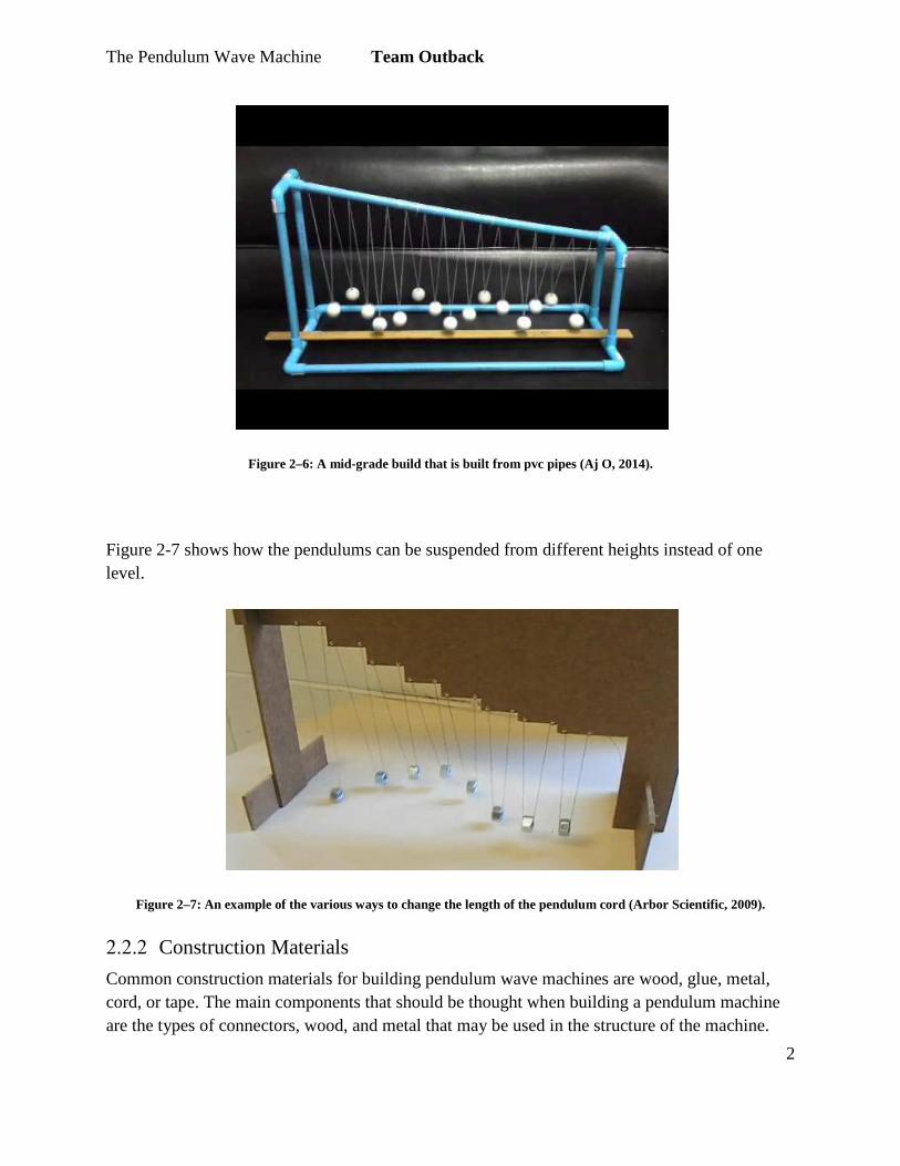
Figure 2–6: A mid-grade build that is built from pvc pipes (Aj O, 2014).
Figure 2-7 shows how the pendulums can be suspended from different heights instead of one level.
Figure 2–7: An example of the various ways to change the length of the pendulum cord (Arbor Scientific, 2009).
Construction Materials Common construction materials for building pendulum wave machines are wood, glue, metal, cord, or tape. The main components that should be thought when building a pendulum machine are the types of connectors, wood, and metal that may be used in the structure of the machine.

The Pendulum Wave Machine Team Outback
3
2.2.2.1 Connectors Fishing line, thread or duct tape can all be used to connect pendulums to the frame from which they will be suspended. A heavy-duty object that can withstand a lot of wear serves as the ideal type to ensure the machine will last. A material that does not infringe upon the ability for the pendulums to move is also most desirable. Figure 2-8 below shows a pendulum that uses fish eyehooks and a durable type of cord to connect the pendulums to the base of the model. This is crucial to the stability and functionality of the pendulum because the connections are the basic foundation of the machine itself (Scheffler, 2014).
Figure 2–8: An image showing a type of fish-eye pendulum connectors. (Scheffler, 2014).
2.2.2.2 Woods Depending on the quality of pendulum desired, many different types of wood such as softwood, hardwood, reclaimed wood, or virgin wood can be used. Hardwoods are used as a long lasting natural construction material because of their natural strength. Softwoods are used usually used as an inexpensive alternative to hardwoods, but do not last as long (Diffen, 2016). Figure 2-9 gives an example of a soft-grade wood: pine wood.
Figure 2–9: An image showing an example of pinewood (Diffen, 2017).
Figure 2-10 gives an example of what a type of hardwood, Maple, might look like. This would be a more desirable type of wood for a more sturdy pendulum (Diffen, 2017).
The Pendulum Wave Machine Team Outback
4
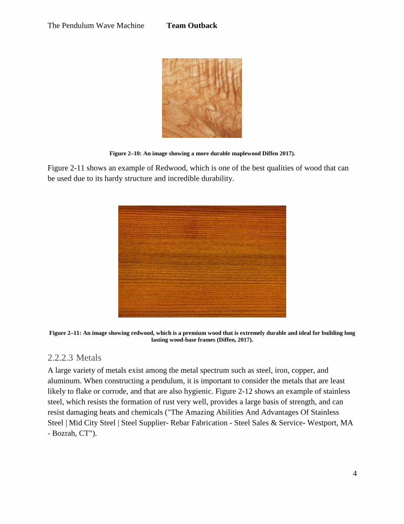
Figure 2–10: An image showing a more durable maplewood Diffen 2017).
Figure 2-11 shows an example of Redwood, which is one of the best qualities of wood that can be used due to its hardy structure and incredible durability.
Figure 2–11: An image showing redwood, which is a premium wood that is extremely durable and ideal for building long lasting wood-base frames (Diffen, 2017).
2.2.2.3 Metals A large variety of metals exist among the metal spectrum such as steel, iron, copper, and aluminum. When constructing a pendulum, it is important to consider the metals that are least likely to flake or corrode, and that are also hygienic. Figure 2-12 shows an example of stainless steel, which resists the formation of rust very well, provides a large basis of strength, and can resist damaging heats and chemicals ("The Amazing Abilities And Advantages Of Stainless Steel | Mid City Steel | Steel Supplier- Rebar Fabrication - Steel Sales & Service- Westport, MA - Bozrah, CT").

The Pendulum Wave Machine Team Outback
5
Figure 2–12: An example of stainless-steel metal (Midc City Steel, 2013).
Audience The target audience for this machine are students aged from K-12, as well as members of the general community who might possibly benefit from deepening their understanding of wave functions.. Understanding how brain growth is key to understanding how humans are able to learn. Neural development impacts how information is transmitted, processed and retained. Visual learning is one of the five types of learning that is commonly used as a learning strategy in teaching science and math. Visual learning is assessed by visual aid like the pendulum wave machine.
2.2.3.1 Background on Brain Development A study on brain development discussed that human brain development begins from the formation of initial neural cells throughout late adolescence and possibly a full lifespan (Stiles, 2010). Processes that great influence brain development are gene expression as well as environmental processes. These processes are highly influential in forming the human brain due to their ability to cause significant alterations in neural growth. Brain maturation undergoes neural competition during fetal stage and continues to influence neural competition, which thus affects the brain’s capacity to function, such as learning, during postnatal life (Stiles, 2010).
2.2.3.2 Brain-Based Learning Due to the larger understanding of how brain development influences learning, different advances in neurological research have enhanced educational systems. School systems considered to be more progressive are found to be implementing positive reforms in children’s learning at school that parallel key findings in the neurological research (Madrazo, 2005). Therefore, understanding how the human brain transmits and processes information aids in understanding how children learn. The brain contains millions of neurons and is divided into a right and left hemisphere. Each hemisphere is equal to the other in terms of brainpower,
The Pendulum Wave Machine Team Outback
6
however, each hemisphere serves as a different medium in receiving and processing information. The two hemispheres of the brain have different specific functions in cognitive, affective and physical activities that the human body encounters on a daily basis. Due to the complexities of brain anatomy and processes, it is understandable that every child’s brain matures differently, which thus results in different ways of thinking and interpreting. Therefore, as neurological studies have revealed, it is best to use multi-dimensional teaching models to address the different learning styles of children (Duman, 2010).
2.2.3.3 Visual Aid Concepts taught in science are often times difficult to teach in verbal expression and best taught through visual aids and physical demonstrations. Peggy Ashbrook, author of Drawing Movements, explains how visual literacy is important in teaching physical science of motion and its engineering applications. For example, Ashbrook asks her students to draw pictures of what happens when a ball is rolling down an incline, and in doing so, allows her students to express their mental analysis through their drawings. Her students are therefore able to observe and understand the physical action of the ball more closely, interpret critical concepts in their own way, and better retain the information that they absorb (Ashbrook, 2012).
Wave Mechanics Basic wave theory serves as a fundamental understanding of general wave mechanics and establishes that a wave is the creation of a disturbance independent of the motion of a medium (Mathematics, 2000). Waves are defined as the disturbance in the time space continuum created at any given moment, therefore acting as disturbances. Moreover, waves can be measured by taking the displacement of the wave as a function of time, as well as by taking the displacement of a wave over as a function of a determined distance. (LibreTexts, 2015). The graph of a wave would thus result in either distance v. displacement or time v. displacement.
2.2.4.1 Wave Properties and Physics All waves exhibit and possess principal properties that determine their categorization as a wave. The measurement of the total displacement of a wave from its original position at equilibrium to any given point is called the amplitude of the wave. Using the amplitude, it is possible to measure the period of a wave as well as its wavelength. Related to amplitude would be the intensity of a wave. The intensity of a wave is just the value of the overall displacement of a wave squared (“Topic 5. General properties of waves,” n.d.). Furthermore, the period of a wave is the measure of the time between any two peaks in a wave function on a displacement vs. time graph as shown in Figure 2-13.

The Pendulum Wave Machine Team Outback
7
Figure 2–13: A wave’s displacement vs time (Sengpiel, 2014)
The period of a wave can be measured by recording the displacement of a wave at any single point and is measured in units of time such as seconds (“Topic 5. General properties of waves,” n.d.). Wavelength is a measurement of the displacement of a wave over a given distance. The wavelength, often referred to as lambda (λ), is also measured from peak to peak on a graph. The graph showing wavelength is different from a wave’s period as it is a wave’s total displacement as a function of distance traveled rather than time as demonstrated by Figure 2-14.
Figure 2–14: A graph showing a wave’s displacement v. distance (Sengpiel, 2014).
Wavelength is a function of distance traveled, and therefore measured in units of distance such as meters, unlike the period and its measurement of time. Another wave property is the frequency of a wave, measured by the number of cycles completed, or rather how many periods are included in one second. This can also be referred to as oscillation (“Topic 5. General properties of waves,” n.d.). This pattern can be seen in Figure 2-15 with an example of high frequency and low frequency waves.

The Pendulum Wave Machine Team Outback
8
Figure 2–15: Examples of wave frequency (“Web-based technology education--music in the digital world,” n.d.)
As seen in Figure 2-16, higher frequency waves have more periods per given amount of time than lower frequency waves. The unit for frequency is often measured in the unit Hertz (“Topic 5. General properties of waves,” n.d.). Additionally, the phase of a wave is also a fundamental wave property. Choosing a specific point and displacement of a wave and taking the time at which the wave passes through those two points measures the phase of a wave. A wave property that can be calculated is the wave speed, or rather velocity. The velocity can be calculated using the wavelength and either the frequency or period of a wave. Wave velocity is equal to the wavelength over the period, which is also equal to the wavelength multiplied by the frequency. Either Way, the velocity of a wave is represented by the equation V=λf (Figueroa, 2017). A final property of waves is resonance. Resonance occurs when a wave is reflected over itself, which thus creates repeated oscillations through the wave pattern (Figueroa, 2017). Figure 2-16 below illustrates the reflections that create resonance within a wave.
Figure 2–16: An image depicting wave resonance (Figueroa, 2017).
The Pendulum Wave Machine Team Outback
9
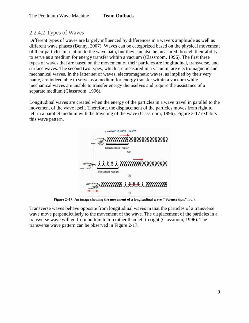
2.2.4.2 Types of Waves Different types of waves are largely influenced by differences in a wave’s amplitude as well as different wave phases (Benny, 2007). Waves can be categorized based on the physical movement of their particles in relation to the wave path, but they can also be measured through their ability to serve as a medium for energy transfer within a vacuum (Classroom, 1996). The first three types of waves that are based on the movement of their particles are longitudinal, transverse, and surface waves. The second two types, which are measured in a vacuum, are electromagnetic and mechanical waves. In the latter set of waves, electromagnetic waves, as implied by their very name, are indeed able to serve as a medium for energy transfer within a vacuum while mechanical waves are unable to transfer energy themselves and require the assistance of a separate medium (Classroom, 1996). Longitudinal waves are created when the energy of the particles in a wave travel in parallel to the movement of the wave itself. Therefore, the displacement of the particles moves from right to left in a parallel medium with the traveling of the wave (Classroom, 1996). Figure 2-17 exhibits this wave pattern.
Figure 2–17: An image showing the movement of a longitudinal wave (“Science tips,” n.d.).
Transverse waves behave opposite from longitudinal waves in that the particles of a transverse wave move perpendicularly to the movement of the wave. The displacement of the particles in a transverse wave will go from bottom to top rather than left to right (Classroom, 1996). The transverse wave pattern can be observed in Figure 2-17.

The Pendulum Wave Machine Team Outback
10
Figure 2–18: An image showing the movement of a transverse wave (PowerSchool, 2005).
Surface waves have particles that move with circular motions, both parallel and perpendicular to the movement of the wave (Classroom, 1996). In some cases, surface waves are combinations of transverse and longitudinal waves and their unique pattern can be seen in Figure 2-18.
Figure 2–19: An image showing the movement of surface waves (“20.01.04 - other waves (physics),” n.d.).
Client Criteria On February 13, 2017, a meeting was held with the client, Ken Pinkerton to discuss details about the Pendulum Wave Machine. Mr. Pinkerton’s desired product consisted of an apparatus that demonstrates traversed waves with varying periods that cycles back to its linear form. Mr. Pinkerton is a retired teacher from Zane Middle School, but still involved in the middle school’s engineering program. He is also involved in the community’s STEM-related events, such as the Humboldt Math Fair. The originally proposed criteria by Mr. Pinkerton are listed as follows:
- Must be able to fit a 36 inches by 18 inches table -The structure of the machine has to be stable and durable -The machine should be portable
-The machine must be finished by April 29th for the Humboldt Math Festival

The Pendulum Wave Machine Team Outback
11
3 Search for Alternative Solutions
Introduction Alternative solutions for the Pendulum Wave Machine have been created as a result of a collaborative and cooperative brainstorming session held between all four Team Outback members. These solutions are designed to satisfy all specifications and requirements of the Pendulum Wave Machine. A total of eight alternative solutions have been created.
Brainstorming Team Outback met for one collective brainstorming session to share ideas for the Pendulum Wave Machine. During this session, all team members were able to voice his/her ideas and the team was able to reflect on all ideas as a whole. After all the ideas were listed out, they were each carefully inspected and compressed down to a list of eight alternative solutions. The purpose of doing this was to ensure that every group member was able to contribute ideas to the project and the group was able to effectively analyze options and select different options that appear to be the most viable. The list created in the brainstorm can be found in Appendix A.
Alternative Solutions The following eight alternative solutions have been collectively created in a group brainstorm and thoroughly thought out and prospectively planned. The planning is done by sketching or creating a digital model of each possible solution and then comparing the alternative solution to the specifications and criteria of the project itself. These solutions will be used to compare and contrast which solution best meets all of the criteria and should be chosen for the final design.
Lock & Key Pendulum The Lock & Key Pendulum model features an alternating set of locks and key as pendulums. As shown by Figure 3-1, the lock & key design is constructed of a wooden base around 3 feet in length frame, four stainless steel columns about a foot high, and a medium duty wire cord attaching the lock & key pendulums to the supporting beam. The pendulums of this model, although alternating in make, are of the same mass to meet the functionality and educational criteria. This model is of the correct size to be able to easily carry and store. The lock & key aspect of the model serves as a unique feature and meets the inspirational criterion of the project. The model’s a-frame creates a durable structure, and all materials used comply with OSCA safety standards. This model is also completely constructible within the given budget of $400.

The Pendulum Wave Machine Team Outback
12
Figure 3–1: A lock and key pendulum utilizes locks and keys on every other cord to inspire middle school students to take
an interest is basic wave behavior (Image edited by Gabriel Garcia).
Light-Up Shadow Wave The Light-Up Shadow Wave model is a wave machine built with L.E.D. lighting to create illusionary shadow waves. Figure 3-2 shows a sketch of the basic structure of the model. The base of the pendulum machine is made of plywood and has a length of 36 inches, a width of 18 inches and is 2 inches thick. The corners of the plank will be carved out to fit 2 x 2 inch wooden stands. Upon the top of the wooden frame structure, a triangular-shaped piece of wood attaches, serving as the supporting beam of the model. The beam supporting the pendulums is the same length as the plywood and is lined with an L.E.D. light strip attached to the bottom of the triangular beam, facing the floor of the machine. The purpose of the L.E.D. light strip is to cast direct light upon the pendulums, allowing the pendulums to create shadows while in motion. The unique visual experience created by the model provides inspirational and educational value for the viewer. The lighting is properly installed as to comply with the safety criterion and handles installed on the sides of the machine satisfy the portability criterion.

The Pendulum Wave Machine Team Outback
13
Figure 3–2: Light-Up Shadow Wave has two main features: LED light system that is attached to its structure to cast a shadow and the balls will glow in the dark (Image by Lorenz Hernandez).
Solid Lead Pendulum The Solid Lead Pendulum is created using solid lead balls with approximately 1” diameters. The lead balls are coated with a clear rubber coating for compliance with OSHA safety standards. The pendulum is constructed using a solid wood base of approximately three feet in length and two inch thickness. The base of the pendulum is a foot wide and the total structure it two feet tall, so that the dimensions and amount of material used do not interfere with the machine’s portability and storability. The lead pendulums hang at different lengths so that they hang at an approximately 25° angle. This angle is shown by label 1 in Figure 3-3. Each string supporting a pendulum is placed four inches apart so that the edge of each pendulum’s radius is approximately two inches apart. This design ensures that the pendulum creates a wave pattern that can serve as a tool in educating the public on wave pattern and behavior. The pendulums hang by industrial strength fishing line from hooks that are screwed into the wooden top of the pendulum structure. The top is supported on either side by wooden panels all carefully joined together and reinforced with screws. The design of the pendulum structure provides reliable durability and increases the longevity of the machine’s lifespan.
Figure 3–3: A basic design of the setup of the solid lead pendulum (Drawing by Maria Garcia)

The Pendulum Wave Machine Team Outback
14
Interchangeable Pendulum The Interchangeable Pendulum is a wave machine that allows different items with equivalent weights to be used during demonstration. A sketch of the Interchangeable Pendulum is shown below in Figure 3-4. This design is mainly composed of wood and metal braces. The base has a length of 36 inches, width of 18 inches and height of 4 inches. Its thickness supports the metal corner braces that are nailed in from the plywood base to the framing lumbers. The purpose of the thick foundation and metal braces is to ensure durability and stability. The nylon strings that the pendulums hang from is held by a long metal beam connected to two planks. The planks are attached to the framing lumbers using wood glue and metal braces. The ends of the nylon strings each have clips that can hold the interchangeable objects. The presenter provides objects to the audience to ensure that the weights of each object are equal.
Figure 3–4: Interchangeable Pendulum is durable and stable with interchangeable weights for demonstration (Image by
Lorenz Hernandez).
Driving Pendulum The Driving Pendulum uses two different sized balls to force the pendulum to move. The machine functions by having a pendulum ball with a larger mass than the others being brought back and released in the direction of the other pendulums, allowing its force to propel the other balls. As shown in Figure 3-5, the pendulums all hang on a line that is suspended from a wooden beam. The driving blob hangs lower than the others and the line has an increasing slope starting from the initial pendulum’s length. The pendulums are 1” lead balls that are covered in a liquid rubber coating to ensure compliance with OSCA safety standards. Each pendulum measures 2” away from each other to prevent them from hitting each other when they move. Braided fishing

The Pendulum Wave Machine Team Outback
15
line is used to keep the balls attached to the machine due to its ability to handle enough tension created by the pendulums, and its ability to swing back and forth smoothly. The line that dangles across the frame uses steel wire to ensure that it does not come apart and is able to hold the weight of all the pendulums. The structure utilizes wood and metal braces to provide a strong base in case of accidental bumping or movement.
Figure 3–5: A driving pendulum with a basic outline of the dimensions (Image by Jordan Huber).
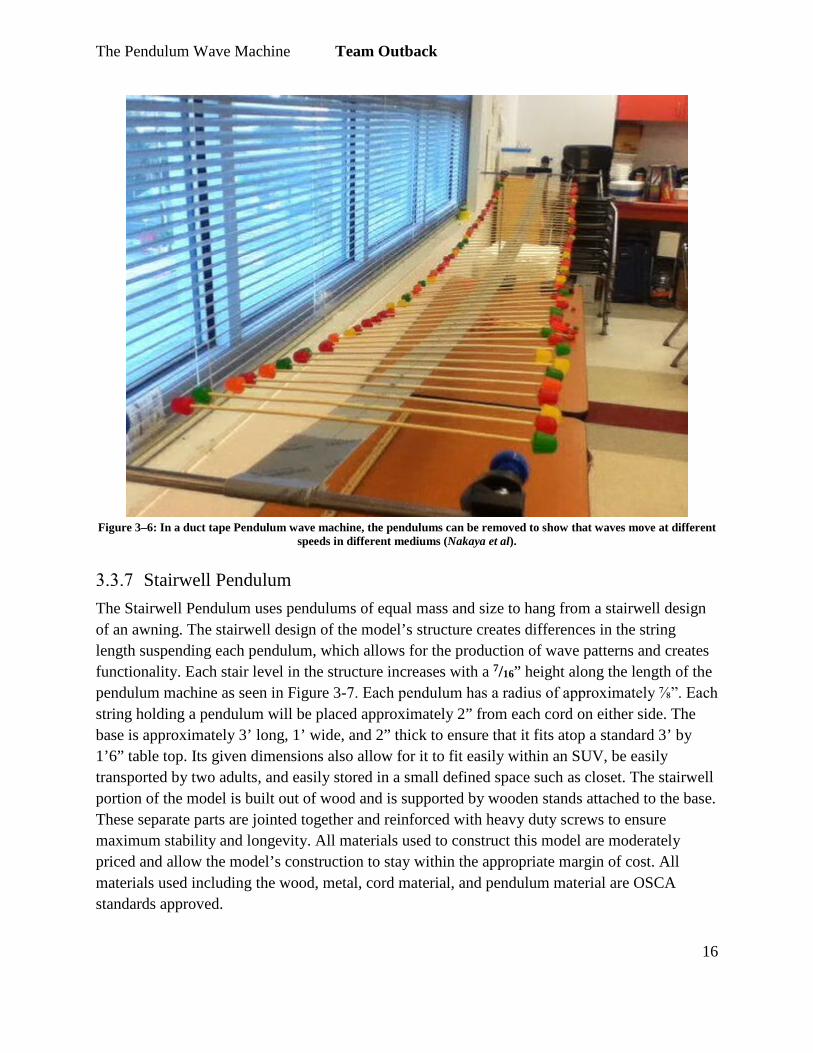
Tape Pendulum The Tape Pendulum model uses sticks equally balanced on either side lining an upside down piece of duct tape to create surface waves. Utilizing two posts that are around 3 feet apart as the overall structure, and connecting duct tape to both posts build the model. The pendulums of this model are the weights on either side of the sticks that line the duct tape. The pendulums can be removed from the ends to make the speed of the wave go faster. The removal of the pendulums demonstrates how waves move at different speeds in different mediums and increases the educational value of the machine. Figure 3-6 shows the build of the tape pendulum and its low-grade structure. The nature of this machine allows for the use of cheap and low-risk materials. The durability and stability of the model can be improved by placing another piece of duct tape underneath the first piece. The dimensions of this model allow for easy transporting and storing of the model. The removable pendulums and use of candy as pendulums create a unique factor that creates inspirational value for this model.
The Pendulum Wave Machine Team Outback
16
Figure 3–6: In a duct tape Pendulum wave machine, the pendulums can be removed to show that waves move at different
speeds in different mediums (Nakaya et al).
Stairwell Pendulum The Stairwell Pendulum uses pendulums of equal mass and size to hang from a stairwell design of an awning. The stairwell design of the model’s structure creates differences in the string length suspending each pendulum, which allows for the production of wave patterns and creates functionality. Each stair level in the structure increases with a 7/16” height along the length of the pendulum machine as seen in Figure 3-7. Each pendulum has a radius of approximately ⅞”. Each string holding a pendulum will be placed approximately 2” from each cord on either side. The base is approximately 3’ long, 1’ wide, and 2” thick to ensure that it fits atop a standard 3’ by 1’6” table top. Its given dimensions also allow for it to fit easily within an SUV, be easily transported by two adults, and easily stored in a small defined space such as closet. The stairwell portion of the model is built out of wood and is supported by wooden stands attached to the base. These separate parts are jointed together and reinforced with heavy duty screws to ensure maximum stability and longevity. All materials used to construct this model are moderately priced and allow the model’s construction to stay within the appropriate margin of cost. All materials used including the wood, metal, cord material, and pendulum material are OSCA standards approved.

The Pendulum Wave Machine Team Outback
17
Decreasing Pendulum The Decreasing pendulum model has pendulum balls that are hung at smaller and smaller lengths as moving towards the right of the machine to show how the length of string effects a pendulum’s motion. This model is constructed using a wooden frame 3’ long and 6” wide. The machine uses metal fish-eye hooks to suspend the pendulums in place. The pendulums of this model are 1” lead balls covered in a liquid rubber coating to comply with OSCA safety standards. Braided fishing line is used to tie the lead balls to the wooden bar and wooden bases surrounding the frame ensure that the pendulum is secure and sturdy when upon a standard tabletop. The pendulums of this machine are spaced out 2” from each other, and the lengths of the fishing line holding the pendulums decreases by ¼”. The longitudinal pattern of waves created by the driving pendulum increase the model’s educational value and inspirational value. The simple design of the machine allow for the model to be easily moved and stored in a defined space. This machine is constructed using a small amount of materials allowing for minimal costs.
Figure 3–7: A diagram illustrating the stairwell effect in the structure of the pendulum (Drawing by Maria Garcia).

The Pendulum Wave Machine Team Outback
18
4 Decision Phase
Introduction The purpose of the decision phase is to analyze the solutions proposed in Section 3 and the criteria in Section 2 to choose an efficient final design. This process is completed using a Delphi Matrix, which uses the criteria of the project in Section 2 to effectively weigh each alternative solution.
Figure 3–8: Figure 3-8: A simple decreasing pendulum that shows (Image by Jordan Huber).

Criteria Definition The criteria, previously mentioned in Section 2 of the document, are defined as follows: Functionality: The ability of the model to create a uniform wave pattern without any disturbances. Portability: The ability of the model to be transported from one location to another. Storability: The ability for the model to fit within a defined space. Cost: The ability of the project to be constructed for a total cost the set price in Section 2. Safety: The ability of the project to follow all health and safety codes associated with using hazardous materials and structures. Durability: The ability of the model to support itself and withstand repeated use. Inspiration: The ability of the project to display a unique design different from previous models of pendulums. Education: The ability of the model to enlighten its audience of the basic functions of waves and their processes.
Solutions The list of possible solutions, as described under Alternative Solutions in section 3, includes:
● The Solid Lead Pendulum ● The Interchangeable Pendulum ● The Driving Pendulum ● The Tape Pendulum ● The Decreasing Pendulum ● The Stairwell Pendulum ● The Lock & Key Pendulum ● The Light-Up Shadow Wave Pendulum

Decision Process The decision process of the project included the use of a Delphi Model to identify a solution that best meets each criterion mentioned in Section 2 . The Delphi Model, shown in Table 4-2, works by first weighing each criterion on a scale of 1-10, with 10 being the highest score, of how important each criterion is to the overall structure of the project. Then, a score is assigned to each alternative solution on a scale of 1-50, with 50 being the highest score, of how well each solution meets each criterion. Its respective criterion’s weight score to get an overall number multiplies each score assigned to each alternative solution. From there, all the numbers for each alternative solution are summed together to produce a final score that represents the solution’s ability to comply with the weighted criteria. Using this method, the solution that best fits the needs of the project is easily identifiable as it is the solution with the highest score.
Figure 4–1: The Delphi Model used in making a final decision for the Pendulum Wave Machine.

The Pendulum Wave Machine Team Outback
2
The weights of each criterion dictating the pendulum wave machine are presented below in Table 4-1.
Table 4-1: A Table of each criterion and their respective weight in terms of importance to overall project.
Criteria Weight
Durability 10
Functionality 10
Safety 10
Cost 9
Education 8
Inspiration 8
Portability 8
Storability 8
Final Decision Justification The final model chosen to serve as the pendulum wave machine’s final design is the Light-Up Shadow Wave option. This model received the highest score using the Delphi Matrix to assess its ability to meet each criterion. The L.E.D light features and the strong structure of the Light-Up Shadow Wave option make it a better fit for the project in comparison to its closely scored alternative solutions. The creative aspects of this model and its ability to satisfy each weighted criterion make it the final decision for the pendulum wave machine.

The Pendulum Wave Machine Team Outback
3
5 Specification of Solution
Introduction Section 5 is an analysis of the final solution, including an examination of the four main components of the design. This section includes a detailed account of the total costs, both monetary and timely, of the project, and implementation instructions and report of the final results.
Solution Description The pendulum wave machine is a model that utilizes L.E.D lighting features, crystal pendulums, and a collapsible design as the final solution to meet the necessary criteria. The model is comprised of a hollow wooden base with a collapsible a-frame structure that holds a beam suspending 8 multifaceted glass pendulums. The frame also contains a L.E.D. light circuit that shines directly on each pendulum to create unique lighting effects as the pendulums swing from side to side.
Wooden Base The wooden base of the pendulum is designed for the model to be collapsible and fit within the base of the pendulum. As seen in Figure 5-1, the base of the model measures 36” long and 18” wide. It is constructed using a frame built from 2x4” pieces of wood and uses two faces of plywood of ½” thickness using 8x2½” screws. The base has holes of ⅞” diameter drilled uniformly into the base directly under each pendulum as to allow for the L.E.D lighting to reach from the inside of the base to the hanging pendulums. The top of the base also has 4 holes of 3” depth, 3” away from each corner of the base at a 45 degree angle. These holes serve as the support structure for the metal a-frame. The wooden base is coated in water based rubbing stain and finish.

The Pendulum Wave Machine Team Outback
4
Figure 5–1: AutoCAD drawing by Maria Garcia showing the dimensions and basic setup of the wooden base in the
design.
A-Frame Structure The a-frame components of the model are made to hold the beam that suspends the pendulums. The steel metal a-frames thread through the wooden beam and are able to swivel freely within the wooden beam to allow them to become completely flat, therefore catering to the collapsible feature of the model. The a-frame is constructed using 66” long metal rods, bent at an approximately 110-degree angle on either side of the wooden beam in which they rest. The steel rods are strong enough to support up to 30lbs of weight and are rust resistant.
Beam Structure & Pendulums The wooden beam that supports the pendulums is a 2x4” wooden beam of 30” in length. The beam has a ¼” hole drilled 1” down the side of the beam on both ends to allow for the a-frame to rest. The top of the beam has two smalls holes that are 40mm apart drilled through it starting 61mm from the edge of the beam. Strings are threaded through each hole drilled in the beam and two strings connect to each pendulum. The dimensions of the beam are shown in Figure 5-2 below.

The Pendulum Wave Machine Team Outback
5
Figure 5–2: AutoCAD drawing by Gabriel Garcia showing the dimensions of the supporting beam.
L.E.D Light Structure The LED light structure has components of wires, resistors, LED lights, heat shrinks, USB port charger and wood. 5mm diameter L.E.D. lights are used and wired together in parallel. The lights are in series with 150-ohm resistors. The voltage drop across each light and resistor is 2.85 Volts and current of 19 mA. To avoid fire hazards, heat shrink is placed around all of the wires. The circuit is then attached to a wooden board to hold it in place. This board can easily be attached to the inside of the base of the pendulum. The wooden board with circuit is pushed through the predrilled holes in the base and nailed for permanent placement. The design of the circuit board can be seen in Figure 5-4 below.
Figure 5–3: AutoCAD drawing by Lorenz Hernandez depicting the L.E.D. light circuit board.
The Pendulum Wave Machine Team Outback
6
Cost Analysis This section lays out the total costs of the project. The types of costs included in this section are the cost of the design in labor time, constructions costs, as well as the cost of the maintenance costs.
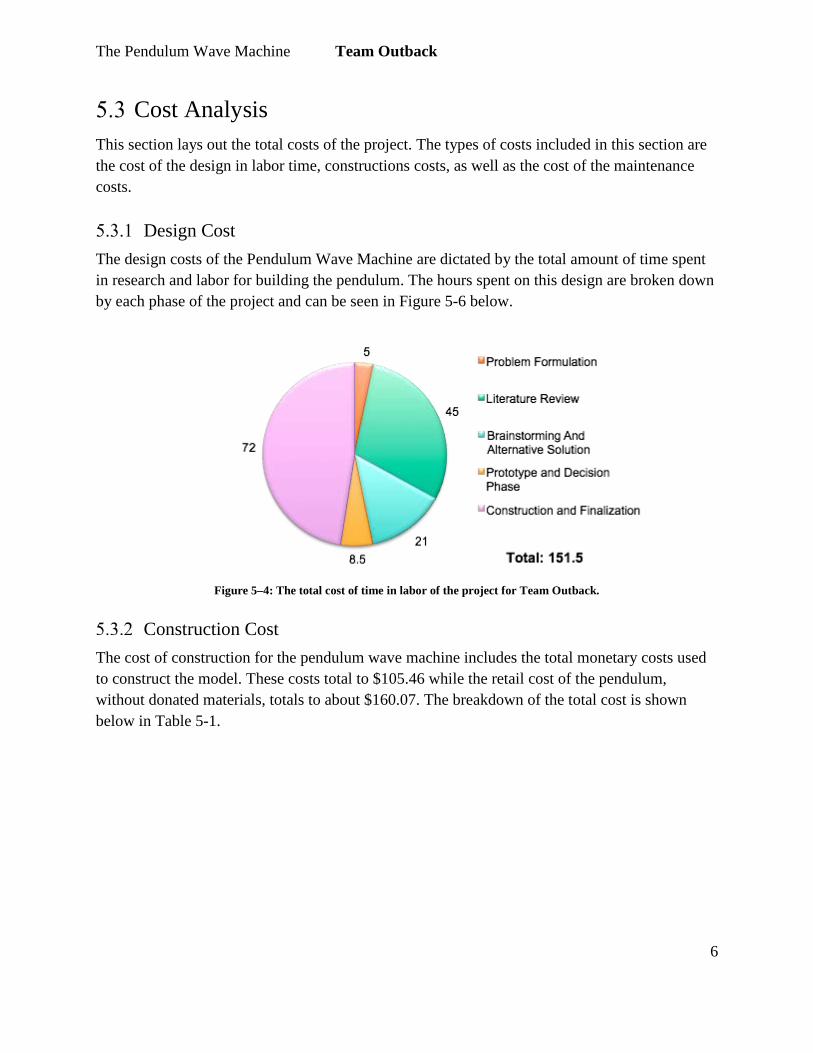
Design Cost The design costs of the Pendulum Wave Machine are dictated by the total amount of time spent in research and labor for building the pendulum. The hours spent on this design are broken down by each phase of the project and can be seen in Figure 5-6 below.
Figure 5–4: The total cost of time in labor of the project for Team Outback.
Construction Cost The cost of construction for the pendulum wave machine includes the total monetary costs used to construct the model. These costs total to $105.46 while the retail cost of the pendulum, without donated materials, totals to about $160.07. The breakdown of the total cost is shown below in Table 5-1.

The Pendulum Wave Machine Team Outback
7
Table 5-1: A breakdown of the project’s individual costs for materials and construction.
Maintenance Cost The maintenance cost of the pendulum wave machine is the projected cost of maintenance of quality for the project. The annual projected maintenance cost for the pendulum wave machine is $5.30 as shown in Table 5-2 below.

The Pendulum Wave Machine Team Outback
8
Table 5-2: A table showing the projected annual maintenance cost for the model.
Implementation Instructions
For implementation of the Pendulum Wave Machine as a tool in demonstrating wave behavior, it is necessary to first assemble the model. Implementation begins with the removal of the back of the pendulum’s base and the removal of the a-frame structure of the pendulum inside the case. The a-frame of the pendulum is unfolded and inserted into the designated holes on the base of the pendulum. The assembler of the machine should apply the necessary pressure on the beam of the machine for the a-frame to be fully inserted into the base and for stability to be maximized. The pendulums are to be properly aligned and any tangles in the pendulum’s lines removed. The pendulum should also be plugged into a power source so that the L.E.D lights are able to turn on. In order to use the pendulum, one must simply take the wooden board provided, align it with the pendulums, lift the pendulums about forty-five degrees, and release. From here the pendulum will do the rest of the work, revealing how waves move and the different patterns they follow.
Figure 5–5: A step-by-step diagram of how to assemble the model.

The Pendulum Wave Machine Team Outback
9
Results/Performance The final model of the Pendulum Wave Machine is a fully functional educational tool. The pendulum is fully storable, portable functional, and compliant with predetermined safety standards. The model is also very heavy-duty and in standards with durability. The pendulum is able to create basic wave patterns with uniform harmonic pattern. When members of the community use the machine, they are better able to visual wave patterns and understand what affects waves. For example, in seeing the different lengths of string from which each pendulums swing, members of the community are able to see how the formula for a period of a wave in Section 2 under Formulas/Units functions in reality. Figure 5-8 below shows members of the community engaging with the machine and finding inspiration in the actions of the model.
Figure 5–6: An image showing members of the community actively learning about basic wave function.

The Pendulum Wave Machine Team Outback
10
6 Appendices:
References "The Amazing Abilities And Advantages Of Stainless Steel | Mid City Steel | Steel Supplier- Rebar Fabrication - Steel Sales & Service- Westport, MA - Bozrah, CT". Midcitysteel.com. N.p., 2017. Web. 7 Apr. 2017. Administrator. "How Does It Work." Welcome to the NAWCC! NAWCC, 2016. Web. 22 Feb. 2017. http://www.nawcc.org/index.php/just-for-kids/about-time/how-does-it-work?highlight=WyJob3ciLCJkb2VzIiwiaXQiLCJpdCdzIiwiaXQnbGwiLCJ3b3JrIiwiaG93IGRvZXMiLCJob3cgZG9lcyBpdCIsImRvZXMgaXQiLCJkb2VzIGl0IHdvcmsiLCJpdCB3b3JrIl0 Ashbrook, P. s. (2012). Drawing Movement. Science & Children, 50(3), 30. Retrieved February 22, 2017 Baez, J., & Chowdry, A. (2016). The Harmonograph. Retrieved February 23, 2017, from http://math.ucr.edu/home/baez/harmonograph/ Benney, D. (2007). Some mathematical properties of long waves. , 205-210 "Barton's Pendulum." Barton's Pendulum. Harvard University, n.d. Web. 22 Feb. 2017. http://www.fas.harvard.edu/~scidemos/OscillationsWaves/BartonsPendulum/BartonsPendulum.html Classroom, T. P. (1996). Categories of waves. Retrieved February 20, 2017, from http://www.physicsclassroom.com/class/waves/Lesson-1/Categories-of-Waves Duman, Bilal. (2010). The Effects of Brain-Based Learning on the Academic Achievement of Students with Different Learning Styles. Education Sciences: Theory & Practice, 2077-2103. Retrieve on February 22, 2017 "Exploring Pendulums." Exploring Pendulums - Science NetLinks. AAAS, 2017. Web. 22 Feb. 2017. http://sciencenetlinks.com/lessons/exploring-pendulums/

The Pendulum Wave Machine Team Outback
11
Figueroa, C. (2017). Transverse Waves and Resonance. Retrieved February 22, 2017, from http://www.cabrillo.edu/~cfigueroa/lectures/10Lecture/10_lecture_9_waves_sum12.pdf "Hardwood vs Softwood." Diffen.com. Diffen LLC, n.d. Web. 22 Feb 2017. < http://www.diffen.com/difference/Hardwood_vs_Softwood > Hooke, R. (2006). Robert Hooke: Tercentennial studies. Retrieved from https://books.google.com/books?id=P0-XfTTcwwQC&pg=PA3&lpg=PA17&dq=Nauenberg+Robert+hooke+orbital+seminal&source=bl&ots=zO22H8fKNA&sig=8s2F9CBhTetr28uvBeFuaEQoMik&hl=en&#v=onepage&q=Nauenberg%20Robert%20hooke%20orbital%20seminal&f=false LibreTexts, C. (2015, January 18). 8.6: Wave mechanics. Retrieved February 18, 2017, from https://chem.libretexts.org/Textbook_Maps/General_Chemistry_Textbook_Maps/Map%3A_General_Chemistry_(Petrucci_et_al.)/08%3A_Electrons_in_Atoms/8.06%3A_Wave_MechanicsI Madrazo, Jr., Gerry M.,& Motz, LaMoine L. (2005). Brain Research: Implications to Diverse Learners. Science Educator. Vol. 14, No. 1. Retrieve on February 22, 2017 Mathematics, A. J. of (2000). Back matter. American Journal of Mathematics, 122(6), . doi:10.2307/25099041 Nave, R. Pendulum. Retrieved February 23, 2017, from HyperPhysics, http://hyperphysics.phy-astr.gsu.edu/hbase/pend.html Nbi-editor. "Nbi-editor." Mid City Steel. Mid City Steel, 26 Aug. 2013. Web. 23 Feb. 2017. <http://midcitysteel.com/the-amazing-abilities-and-advantages-of-stainless-steel/>. Opanuphong. "Pendulum Wave Machine by Aj O Physics CMRU." YouTube. YouTube, 07 Aug. 2013. Web. 23 Feb. 2017. <https://www.youtube.com/watch?v=37eKvsjbD_U>. Quake makes art. (2001, May 11). Current Science, 86, 12-13. Retrieved from http:// ezproxy.humboldt.edu/login? url=http://search.proquest.com/docrevies/195947917?accountid=11532

The Pendulum Wave Machine Team Outback
12
Science tips. Retrieved February 20, 2017, from https://www.google.com/url?sa=i&rct=j&q=&esrc=s&source=images&cd=&cad=rja&uact=8&ved=0ahUKEwiPi9TcuJ3SAhWki1QKHZ7bBgMQjhwIBQ&url=http%3A%2F%2Fwww.rpdp.net%2Fsciencetips_v3%2FP8C2.htm&bvm=bv.147448319,d.cGw&psig=AFQjCNEzQoX4w4WogZrHLHdpyBRbPO8t4A&ust=1487637735435650 Scheffler, Nathanael. "Pendulum Wave Machine." Instructables.com. N.p., 30 Dec. 2014. Web. 23 Feb. 2017. <http://www.instructables.com/id/Pendulum-Wave-Machine/>. Senior, Tom. "Pendulum Wave: Seems like Magic, but Its Physics!" Arbor Scientific. Arbor Scientific, 1 Oct. 2009. Web. 23 Feb. 2017. <http://www.arborsci.com/cool/pendulum-wave-seems-like-magic-but-its-physics>. Sims, K. (2009). How to make a Three-Pendulum rotary Harmonograph. Retrieved February 23, 2017, from http://www.karlsims.com/harmonograph/ Stiles, J., & Jernigan, T. L. (2010). The Basics of Brain Development. Neuropsychology Review, 20(4), 327–348. http://doi.org/10.1007/s11065-010-9148-4 Systems, A. I. (2012). Simple pendulum. Retrieved February 23, 2017, from College Physics Labs, http://www.webassign.net/question_assets/tamucolphysmechl1/lab_1/manual.htmluses Topic 5. General properties of waves. Retrieved February 19, 2017, from http://www.colorado.edu/physics/phys1230/phys1230_fa01/topic5.html Widnall, S., & Peraire, J. (2008). Retrieved February 23, 2017, from https://ocw.mit.edu/courses/aeronautics-and-astronautics/16-07-dynamics-fall-2009/lecture-notes/MIT16_07F09_Lec24.pdf Wave Motion Resonance. (2016). Retrieved February 23, 2017, from A-level Physics Tutor, http://www.a-levelphysicstutor.com/wav-resonan.php "Wave Machine." Wave Machine | STEM. National STEM Learning Centre and The Institute of Physics, 2010. Web. 23 Feb. 2017. <https://www.stem.org.uk/elibrary/resource/27031/wave-machine>.
The Pendulum Wave Machine Team Outback
13
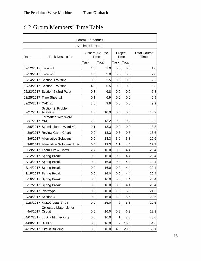
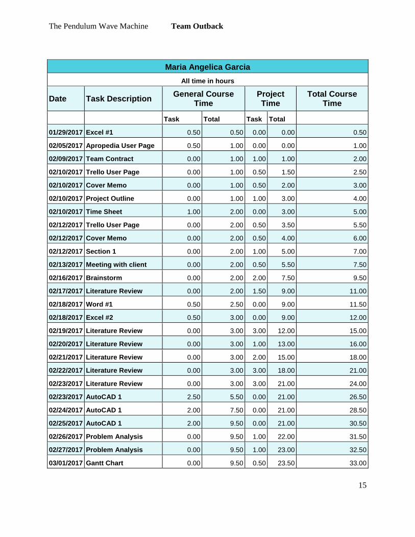
Group Members’ Time Table
Lorenz Hernandez
All Times in Hours
Date Task Description General Course
Time Project Time
Total Course Time
Task Total Task Total
02/12/2017 Excel #1 1.0 1.0 0.0 0.0 1.0
02/19/2017 Excel #2 1.0 2.0 0.0 0.0 2.0
02/14/2017 Section 1 Writing 0.5 2.5 0.0 0.0 2.5
02/23/2017 Section 2 Writing 4.0 6.5 0.0 0.0 6.5
02/23/2017 Section 2 (2nd Part) 0.3 6.8 0.0 0.0 6.8
02/25/2017 Time Sheet#2 0.1 6.9 0.0 0.0 6.9
02/25/2017 CAD #1 3.0 9.9 0.0 0.0 9.9
2/27/2017 Section 2: Problem Analysis 1.0 10.9 0.0 0.0 10.9
3/1/2017 Formatted with Word #1&2 2.3 13.2 0.0 0.0 13.2
3/5/2017 Submission of Word #2 0.1 13.3 0.0 0.0 13.3
3/6/2017 Review Gantt Chard 0.0 13.3 0.3 0.3 13.6
3/6/2017 Alternative Solutions 0.0 13.3 3.0 3.3 16.6
3/8/2017 Alternative Solutions Edits 0.0 13.3 1.1 4.4 17.7
3/9/2017 Team Eval& CatME 2.7 16.0 0.0 4.4 20.4
3/12/2017 Spring Break 0.0 16.0 0.0 4.4 20.4
3/13/2017 Spring Break 0.0 16.0 0.0 4.4 20.4
3/14/2017 Spring Break 0.0 16.0 0.0 4.4 20.4
3/15/2017 Spring Break 0.0 16.0 0.0 4.4 20.4
3/16/2017 Spring Break 0.0 16.0 0.0 4.4 20.4
3/17/2017 Spring Break 0.0 16.0 0.0 4.4 20.4
3/18/2017 Prototype 0.0 16.0 1.2 5.6 21.6
3/20/2017 Section 4 0.0 16.0 1.3 6.6 22.6
3/25/2017 ACE/Crystal Shop 0.0 16.0 3 6.6 22.6
4/4/2017 Collected Materials for Circuit 0.0 16.0 0.8 6.3 22.3
04/07/2017 LED light checking 0.0 16.0 1 7.3 45.6
04/08/2017 Building 0.0 16.0 9 16.3 54.6
04/12/2017 Circuit Building 0.0 16.0 4.5 20.8 59.1
The Pendulum Wave Machine Team Outback
14
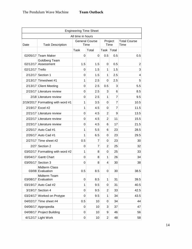
Engineering Time Sheet
All time in hours
Date Task Description General Course
Time Project Time
Total Course Time
Task Total Task Total
02/05/17 Team Maker 0 0 0.5 0.5 0.5
02/12/17 Goldberg Team Assessment 1.5 1.5 0 0.5 2
02/12/17 Trello 0 1.5 1 1.5 3
2/12/17 Section 1 0 1.5 1 2.5 4
2/13/17 Timesheet #1 1 2.5 0 2.5 5
2/13/17 Client Meeting 0 2.5 0.5 3 5.5
2/15/17 Literature review 0 2.5 3 6 8.5
2/18 Literature review 0 2.5 1 7 9.5
2/19/2017 Formatting with word #1 1 3.5 0 7 10.5
2/19/17 Excel #2 1 4.5 0 7 11.5
2/21/17 Literature review 0 4.5 2 9 13.5
2/22/17 Literature review 0 4.5 2 11 15.5
2/23/17 Literature review 0 4.5 6 17 21.5
2/25/17 Auto Cad #1 1 5.5 6 23 28.5
2/26/17 Auto Cad #1 1 6.5 0 23 29.5
2/27/17 Time sheet #2 0.5 7 0 23 30
2/27 Section 2 0 7 2 25 32
03/02/17 Formatting with word #2 1 8 0 25 33
03/04/17 Gantt Chart 0 8 1 26 34
03/05/17 Section 3 0 8 4 30 38
03/08 Midterm Class Evaluation 0.5 8.5 0 30 38.5
03/08/17 Midterm Team Evaluation 0 8.5 1 31 39.5
03/19/17 Auto Cad #2 1 9.5 0 31 40.5
3/19/17 Section 4 0 9.5 2 33 42.5
03/24/17 Worked on Protype 0 9.5 1 34 43.5
04/02/17 Time sheet #4 0.5 10 0 34 44
04/06/17 Appropedia 0 10 3 37 47
04/08/17 Project Building 0 10 9 46 56
4//12/17 Light Work 0 10 2 48 58
The Pendulum Wave Machine Team Outback
15
Maria Angelica Garcia All time in hours
Date Task Description General Course Time
Project Time
Total Course Time
Task Total Task Total
01/29/2017 Excel #1 0.50 0.50 0.00 0.00 0.50
02/05/2017 Apropedia User Page 0.50 1.00 0.00 0.00 1.00
02/09/2017 Team Contract 0.00 1.00 1.00 1.00 2.00
02/10/2017 Trello User Page 0.00 1.00 0.50 1.50 2.50
02/10/2017 Cover Memo 0.00 1.00 0.50 2.00 3.00
02/10/2017 Project Outline 0.00 1.00 1.00 3.00 4.00
02/10/2017 Time Sheet 1.00 2.00 0.00 3.00 5.00
02/12/2017 Trello User Page 0.00 2.00 0.50 3.50 5.50
02/12/2017 Cover Memo 0.00 2.00 0.50 4.00 6.00
02/12/2017 Section 1 0.00 2.00 1.00 5.00 7.00
02/13/2017 Meeting with client 0.00 2.00 0.50 5.50 7.50
02/16/2017 Brainstorm 0.00 2.00 2.00 7.50 9.50
02/17/2017 Literature Review 0.00 2.00 1.50 9.00 11.00
02/18/2017 Word #1 0.50 2.50 0.00 9.00 11.50
02/18/2017 Excel #2 0.50 3.00 0.00 9.00 12.00
02/19/2017 Literature Review 0.00 3.00 3.00 12.00 15.00
02/20/2017 Literature Review 0.00 3.00 1.00 13.00 16.00
02/21/2017 Literature Review 0.00 3.00 2.00 15.00 18.00
02/22/2017 Literature Review 0.00 3.00 3.00 18.00 21.00
02/23/2017 Literature Review 0.00 3.00 3.00 21.00 24.00
02/23/2017 AutoCAD 1 2.50 5.50 0.00 21.00 26.50
02/24/2017 AutoCAD 1 2.00 7.50 0.00 21.00 28.50
02/25/2017 AutoCAD 1 2.00 9.50 0.00 21.00 30.50
02/26/2017 Problem Analysis 0.00 9.50 1.00 22.00 31.50
02/27/2017 Problem Analysis 0.00 9.50 1.00 23.00 32.50
03/01/2017 Gantt Chart 0.00 9.50 0.50 23.50 33.00

The Pendulum Wave Machine Team Outback
16
03/03/2017 Word #2 0.50 10.00 0.00 23.50 33.50 03/03/2017 Group Meeting 0.00 10.00 2.00 25.50 35.50
03/04/2017 AutoCAD2 2.00 12.00 0.00 25.50 37.50
03/04/2017 Secton 3 0.00 12.00 2.00 27.50 39.50
03/05/2017 AutoCAD2 1.00 13.00 0.00 27.50 40.50
03/05/2017 Gantt Chart 0.00 13.00 1.00 28.50 41.50
03/06/2017 Section 3 0.00 13.00 3.00 31.50 44.50
03/07/2017 Section 3 0.00 13.00 1.00 32.50 45.50
03/072017 Midterm Team Eval 1.00 14.00 0.00 32.50 46.50
03/08/2017 Midterm Team Eval 0.50 14.50 0.00 32.50 47.00
03/08/2017 Section 3 0.00 14.50 0.50 33.00 47.50
03/09/2017 Section 3 0.00 14.50 0.50 33.50 48.00
03/10/2017 Delphi Chart 0.00 14.50 1.50 35.00 49.50
03/11/2017 Draft Edits 0.00 14.50 1.50 36.50 51.00
03/11/2017 Delphi Chart 0.00 14.50 0.50 37.00 51.50
03/12/2017 Draft Edits 0.00 14.50 1.00 38.00 52.50
03/13/2017 Section 4 0.00 14.50 2.00 40.00 54.50
03/16/2017 Section 4 0.00 14.50 0.50 40.50 55.00
03/17/2017 Section 4 0.00 14.50 0.50 41.00 55.50
03/20/2017 Delphi Chart 0.00 14.50 0.50 41.50 56.00
03/20/2017 Section 4 0.00 14.50 1.50 43.00 57.50
03/22/2017 Pendulum Research 0.00 14.50 2.00 45.00 59.50
03/23/2017 Group Meeting 0.00 14.50 0.50 45.50 60.00
03/25/2017 Group Meeting 0.00 14.50 3.50 49.00 63.50
03/28/2017 Section 5 0.00 14.50 0.50 49.50 64.00
03/30/2017 AutoCAD #3 0.00 14.50 2.00 51.50 66.00
04/01/2017 Buying Materials 0.00 14.50 2.00 53.50 68.00
04/04/2017 Section 5 0.00 14.50 1.00 54.50 69.00
04/05/2017 Edits 0.00 14.50 1.00 55.50 70.00
04/06/2017 Apropedia User Page 0.00 14.50 3.00 58.50 73.00
04/06/2017 Edits 0.00 14.50 1.00 59.50 74.00
04/08/2017 Building 0.00 14.50 9.00 68.50 83.00

The Pendulum Wave Machine Team Outback
17
04/08/2017 Apropedia User Page 0.00 14.50 2.00 70.50 85.00
04/09/2017 Section 5 0.00 14.50 0.50 71.00 85.50
04/09/2017 Section 5 0.00 14.50 2.00 73.00 87.50
04/11/2017 Building 0.00 14.50 1.00 74.00 88.50
04/12/2017 Building 0.00 14.50 2.00 76.00 90.50
04/13/2017 Building 0.00 14.50 1.00 77.00 91.50
04/14/2017 Presentation Draft 0.00 14.50 0.50 77.50 92.00
04/16/2017 Section 5 0.00 14.50 4.00 81.50 96.00
04/18/2017 Building 0.00 14.50 0.50 82.00 96.50
04/19/2107 Presentation Practice 0.00 14.50 0.50 82.50 97.00
04/20/2017 Edits 0.00 14.50 2.00 84.50 99.00
04/21/2017 Presentation 0.00 14.50 0.50 85.00 99.50
04/22/2017 Buying Materials 0.00 14.50 0.50 85.50 100.00
04/24/2017 Building 0.00 14.50 2.00 87.50 102.00
04/24/2017 Presentation 0.00 14.50 1.00 88.50 103.00
04/25/2017 Presentation 0.00 14.50 4.00 92.50 107.00
04/28/2017 Festival Poster 0.00 14.50 2.00 94.50 109.00
04/29/2017 Humboldt Math Festival
0.00 14.50 5.00 99.50 114.00
04/29/2017 Video 0.00 14.50 2.00 101.50 116.00
04/29/2017 Appropedia 0.00 14.50 2.00 103.50 118.00
04/30/2017 Document Edits 0.00 14.50 4.00 107.50 122.00
04/30/2017 Appropedia 0.00 14.50 3.00 110.50 125.00
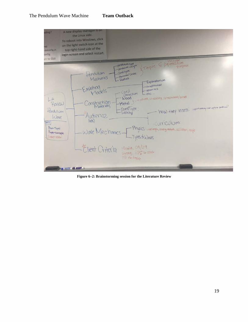
Brainstorm

The Pendulum Wave Machine Team Outback
18
Figure 6–1: Brainstorming from the alternative solutions session.
The Pendulum Wave Machine Team Outback
19
Figure 6–2: Brainstorming session for the Literature Review