the - old dominion universitymln/ltrs-pdfs/nasa-2001-cr210850.pdf · phone the nasa sti help desk...
TRANSCRIPT

NASA/CR{2001{210850
Summary Report of the Orbital X-34Wing Static Aeroelastic Study
Ramadas K. Prabhu
Lockheed Martin Engineering & Sciences Company, Hampton, Virginia
April 2001

The NASA STI Program O�ce ... in Pro�le
Since its founding, NASA has been dedicatedto the advancement of aeronautics and spacescience. The NASA Scienti�c and TechnicalInformation (STI) Program O�ce plays a keypart in helping NASA maintain thisimportant role.
The NASA STI Program O�ce is operated byLangley Research Center, the lead center forNASA's scienti�c and technical information.The NASA STI Program O�ce providesaccess to the NASA STI Database, thelargest collection of aeronautical and spacescience STI in the world. The Program O�ceis also NASA's institutional mechanism fordisseminating the results of its research anddevelopment activities. These results arepublished by NASA in the NASA STI ReportSeries, which includes the following reporttypes:
� TECHNICAL PUBLICATION. Reports ofcompleted research or a major signi�cantphase of research that present the resultsof NASA programs and include extensivedata or theoretical analysis. Includescompilations of signi�cant scienti�c andtechnical data and information deemedto be of continuing reference value. NASAcounterpart of peer-reviewed formalprofessional papers, but having lessstringent limitations on manuscriptlength and extent of graphicpresentations.
� TECHNICAL MEMORANDUM.Scienti�c and technical �ndings that arepreliminary or of specialized interest,e.g., quick release reports, workingpapers, and bibliographies that containminimal annotation. Does not containextensive analysis.
� CONTRACTOR REPORT. Scienti�c andtechnical �ndings by NASA-sponsoredcontractors and grantees.
� CONFERENCE PUBLICATION.Collected papers from scienti�c andtechnical conferences, symposia,seminars, or other meetings sponsored orcosponsored by NASA.
� SPECIAL PUBLICATION. Scienti�c,technical, or historical information fromNASA programs, projects, and missions,often concerned with subjects havingsubstantial public interest.
� TECHNICAL TRANSLATION. English-language translations of foreign scienti�cand technical material pertinent toNASA's mission.
Specialized services that help round out theSTI Program O�ce's diverse o�erings includecreating custom thesauri, building customizeddatabases, organizing and publishingresearch results. . . even providing videos.
For more information about the NASA STIProgram O�ce, see the following:
� Access the NASA STI Program HomePage at http://www.sti.nasa.gov
� E-mail your question via the Internet [email protected]
� Fax your question to the NASA STIHelp Desk at (301) 621{0134
� Phone the NASA STI Help Desk at(301) 621{0390
� Write to:NASA STI Help DeskNASA Center for AeroSpace Information7121 Standard DriveHanover, MD 21076{1320

NASA/CR{2001{210850
Summary Report of the Orbital X-34Wing Static Aeroelastic Study
Ramadas K. Prabhu
Lockheed Martin Engineering & Sciences Company, Hampton, Virginia
National Aeronautics andSpace Administration
Langley Research Center Prepared for Langley Reseach Center
Hampton, Virginia 23681{2199 under contract NAS1-96014
April 2001

Available from the following:
NASA Center for AeroSpace Information (CASI) National Technical Information Service (NTIS)
7121 Standard Drive 5285 Port Royal Road
Hanover, MD 21076{1320 Spring�eld, VA 22161{2171
(301) 621{0390 (703) 487{4650

Summary
This report documents the results of a computational study conducted on the Orbital Sciences X-34 con�gu-ration. The purpose of this study was to compute the inviscid aerodynamic characteristics of the X-34 wingtaking into account its structural exibility. This was a joint exercise conducted with Structural DynamicsResearch Corporation (SDRC) of California, who provided the wing structural deformations for a givenpressure distribution on the wing surfaces. This study was done for a Mach number of 1.35 and an angleof attack of 9 deg.; the freestream dynamic pressure was assumed to be 607 lb/ft2. Only the wing and thebody were simulated. Two wing con�gurations were examined. The �rst had the elevons in the unde ectedposition and the second had the elevons de ected 20 degrees up. The results indicated that with unde ectedelevons, the wing twists by about 1.5 deg. resulting in a reduction in the angle of attack at the wing tip by1.5 deg. The maximum vertical de ection of the wing is about 3.71 inches at the wing tip. For the wing withthe unde ected elevons, the e�ect of this wing deformation is to reduce the normal force coe�cient (CN )by 0.012 and introduce a nose up pitching moment coe�cient (Cm) of 0.042. With the elevons de ected 20degrees up, the e�ects are relatively small. The CN increases by 0.003 and the Cm decreases by 0.013.
Nomenclature
CA Fx/(q1 Sref ), Axial force coe�cient
CN Fz/(q1 Sref ), Normal force coe�cient
Cm My/(q1 Sref lref ), Pitching moment coe�cient
Cp (p - p1)/q1, Pressure coe�cient
Fx Axial force, (lb)
Fy Side force, (lb)
Fz Normal force, (lb)
lref Reference length ( =174.48 in.)
Mx Rolling moment, (ft.lb)
My Pitching moment, (ft.lb)
Mz Yawing moment, (ft.lb)NOTE: The moment reference point is at (0, 0, 0).
M1 Freestream Mach number ( =1.35)
p Static pressure on the wing surface
p1
Freestream static pressure
q1
Freestream dynamic pressure ( =607 lb/ft2)
Sref Reference area ( =51480.0 sq. in.)
x, y, z Cartesian co-ordinates of a given point; (The nose is at 92.62in., 0, -23.62in.)(The x-axis is in the axial direction, the y-axis is in the spanwise direction,and the z-axis is in the vertical direction)
� Angle of attack, deg.
�x, �y, �z Displacements of a point along the x, y, and z axes, respectively, (in.)
1

Figure 1: A Sketch of the X-34 model used for the wing static aeroelastic studies.
Introduction
The purpose of this study was to determine the e�ect of the X-34 wing structural exibility on the staticlongitudinal aerodynamic characteristics. In this study only the wing was assumed to be exible, and allother components of the vehicle were assumed to be rigid. Due to the spanwise load distribution the wing isde ected and due to the chordwise distribution the wing is twisted. Since the wing twist changes the angleof attack along the wing span, it has a much larger impact on the wing aerodynamic characteristics thanthe wing bending. In the present study, the e�ect of the wing exibility on its aerodynamic characteristicsare computed iteratively.
Under a contractual agreement with Orbital Sciences, SDRC of San Diego modeled the structural detailsof the wing. Surface pressures on the Outer Mold Line (OML) were computed at LaRC and transmitted toSDRC. SDRC then transferred the loads to the underlying wing structure, and computed the wing structuralde ections. The de ected wing geometry was then returned to LaRC for further computational analysis.
The major components of the X-34 vehicle are the fuselage, the wing, the body ap, the engine bell, andthe rudder. Of these, the body ap, the engine bell, and the rudder are located su�ciently far behind thewing trailing edge to preclude any upstream in uence on the wing at Mach 1.35. Since the purpose of thestudy was to determine the pressure distribution on the wing and compute its aerodynamic characteristics,it was decided to simplify the computational model by simulating only the wing and the body in the CFDmodel and deleting the body ap, the engine bell, and the rudder. Since the vehicle has a plane of symmetry,only one half of the vehicle was modeled. The CFD model has a wing semispan of 166.30 in. and a lengthof 646.88 in. A sketch of the CFD model is shown Fig. 1.
2

The present studies were conducted for a freestream Mach number of 1.35 and an angle of attack of9 degrees. The freestream dynamic pressure was 607 lb/ft2 which represents the maximum dynamic pressureon a reference trajectory. Two wing con�gurations were studied; the �rst was with the elevons unde ected,and the second was with the elevons de ected 20 deg. up.
The FELISA Software
All the computations of the present study were done using the FELISA unstructured grid software. This soft-ware package consists of a set of computer codes for the simulation of three dimensional steady inviscid owsusing unstructured tetrahedral element grids. Surface triangulation and discretization of the computationaldomain using tetrahedral elements is done by two separate codes. There are two inviscid ow solvers|onefor transonic ows and the other for hypersonic ows with an option for perfect gas air, equilibrium air, andCF4 gases. The transonic ow solver was used for the present study. The ratio of speci�c heats, ( ), wasassumed to be 1.4. Post-processors like the aerodynamic analysis routine used in the study, are part of theFELISA software package. More information on FELISA may be found in [1].
Computers Used
The surface and volume grid generation as well as pre-processing of the grids and post-processing of thesolution was done on an SGI ONYX computer located in the Aerothermodynamics Branch (AB), NASALangley Research Center. After the FELISA data �les were set-up, each surface grid generation requiredabout 30 minutes and each volume grid generation required 4 to 5 CPU hours on the ONYX. Most of the owcomputations were done on SGI origin 2000 series parallel processing computers, each having 64 processorssitting on top of 16G of shared memory. Each computation of the ow solution required 32 to 40 CPU hourson these parallel machines.
The X-34 Geometry and the Grids
The geometrical information of the X-34 was received in the form of an IGES �le with 67 trimmed surfaces.Of these 29 de�ned the body and the remaining 38 surfaces de�ned the wing and elevons. The IGES �le wasprocessed using the software GridTool [2], and a set of FELISA data �les was obtained. The computationaldomain was chosen such that the ow would be contained within this domain except at the out ow boundary.A sketch of the computational domain is shown in Fig. 2.
The FELISA data �les were manually modi�ed so that the desired grid spacings could be obtained. Thegrid spacings were chosen such that on and around the wing the spacings were small. Typically, near thewing leading edge the grid spacing was 0.75 inch at the tip and 1.0 inch near the root. In the far �eld wherethe ow is not in uenced by the vehicle, the grid spacing was large. The FELISA surface grid generator wasused to triangulate the surfaces. A typical surface grid used for the present computations is shown in Fig. 3.
After a satisfactory surface grid was obtained, the FELISA volume grid generator was used to generatean unstructured grid of tetrahedral elements within the computational domain. A typical grid used for thepresent study had about 80,000 points on the surface, and about 650,000 points in the volume grids. All thegrids required for this study were generated on the SGI computer at the Aerothermodynamics Branch.
3

(a) Side view (b) Front view
Figure 2: Computational domain used for X-34 wing static aeroelastic studies.
4

No. of surface points = 78,966No. of surface triangles = 157,928
Figure 3: A typical surface triangulation used for the X-34 wing static aeroelastic studies.
5

Flow Solution
The volume grids were partitioned using the FELISA pre-processor to run on a total of 8 processors. The ow solutions were started with the low-order option and run for a few hundred iteration, and then thehigher-order option was turned on. The pressure distribution on the wing and the body was integrated,and the normal force, axial force, and pitching moment were computed once every 20 iteration steps. Thesolution was assumed to have converged when these loads reached steady values. This normally required atotal of 32 to 40 CPU hours.
The solution was post-processed on the SGI ONYX at the AB. The aerodynamic loads acting on thewing were computed, and the pressure distribution on the wing surfaces were extracted. This informationwas sent to SDRC along with the surface de�nition of the wing, and additional information on the curvesthat were common between the wing and the fuselage. Since the fuselage was assumed to be rigid, thesecurves were constrained and not allowed to undergo any deformation although they were part of the wing.The deformation of the wing due to the prescribed pressure loads was computed by SDRC, and the deformedwing surface geometry was returned to LaRC. This geometry was combined with the data �les, and a newset of FELISA data �les was obtained for the deformed wing after the �rst iteration cycle. These data �leswere then used to generate surface and volume grids for the second iteration cycle.
This process of computing the pressure distribution and a deformed wing shape for the computed pressuredistribution was repeated four times. The loads computed on the vehicle at the fourth iteration cycle werepractically same as the loads computed in the previous cycle. At this point the process was assumed to haveconverged.
Results and Discussion
The X-34 structure lies under a layer of TPS material. Therefore the pressure loads computed on the externalsurfaces (OML) of the vehicle had to be transferred to the structure. Due to the inaccuracies in this loadtransfer process there were some di�erences between the aerodynamics loads (resulting from the integrationof the computed surface pressure distribution) and the actual loads applied to the structure at each iterationsteps. The applied loads de ect the wing structure. Since the de ected wing surface (OML) was requiredfor ow computations, the wing structural de ections had to be transferred back to the wing surface. Thisstep also introduced some inaccuracies.
It should be recalled that the reference point for all the moments is (0, 0, 0). Also, note that the nose ofthe vehicle is at (92.82in., 0, -26.32in.). The dynamic pressure is assumed to be 607 lb/ft2.
Case 1: Elevons Unde ected
The computed aerodynamic loads for the unde ected elevons case are summarized in the Table 1.The actual loads applied to the structure are listed in Table 2. A comparison of Tables 1 and 2 reveals
that the di�erence in the maximum force namely Fz, is about 0.5%, and in the di�erence in the maximummoment namely My, was about 0.4%. These small di�erences are not expected to signi�cantly a�ect the�ndings of the present study.
The undeformed wing tip shape and the deformed shapes are shown in Fig. 4. It may be noticed formthis �gure that there is little di�erence between the tip shapes for the third and the fourth iterations. This isan indication that the process has converged. Similar conclusion may be drawn from Fig. 5 where the linescommon between the wing and the elevons are plotted. The de ections of the leading and trailing edges at
6
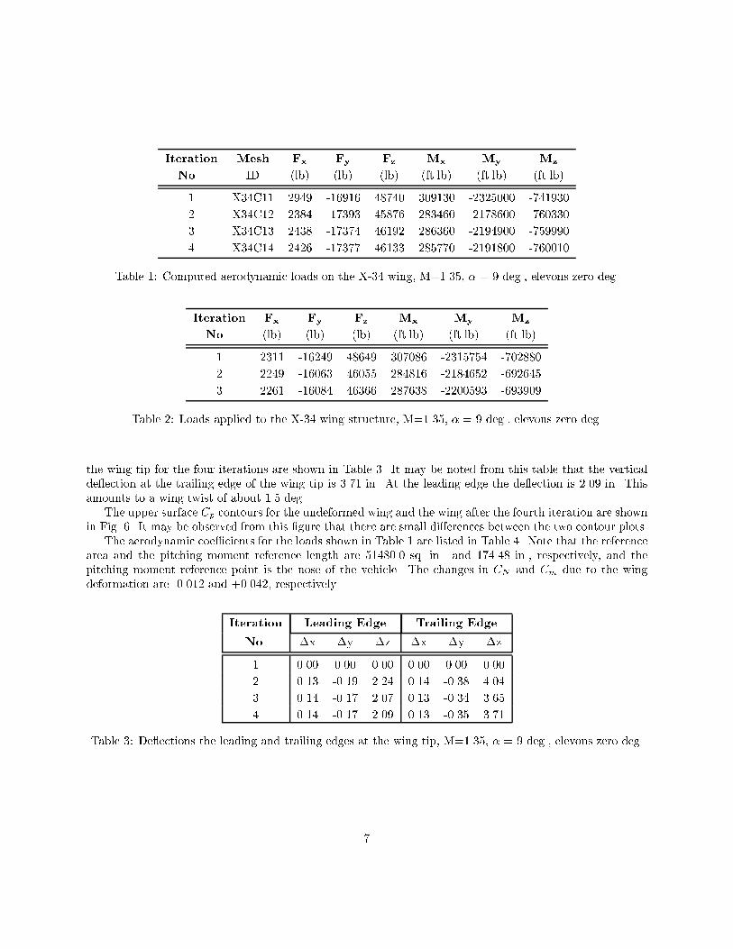
Iteration Mesh Fx Fy Fz Mx My Mz
No. ID (lb) (lb) (lb) (ft.lb) (ft.lb) (ft.lb)
1 X34C11 2949 -16916 48740 309130 -2325000 -741930
2 X34C12 2384 -17393 45876 283460 -2178600 -760330
3 X34C13 2438 -17374 46192 286360 -2194900 -759990
4 X34C14 2426 -17377 46133 285770 -2191800 -760010
Table 1: Computed aerodynamic loads on the X-34 wing, M=1.35, � = 9 deg., elevons zero deg.
Iteration Fx Fy Fz Mx My Mz
No. (lb) (lb) (lb) (ft.lb) (ft.lb) (ft.lb)
1 2311 -16249 48649 307086 -2315754 -702880
2 2249 -16063 46055 284816 -2184652 -692645
3 2261 -16084 46366 287638 -2200593 -693909
Table 2: Loads applied to the X-34 wing structure, M=1.35, � = 9 deg., elevons zero deg.
the wing tip for the four iterations are shown in Table 3. It may be noted from this table that the verticalde ection at the trailing edge of the wing tip is 3.71 in. At the leading edge the de ection is 2.09 in. Thisamounts to a wing twist of about 1.5 deg.
The upper surface Cp contours for the undeformed wing and the wing after the fourth iteration are shownin Fig. 6. It may be observed from this �gure that there are small di�erences between the two contour plots.
The aerodynamic coe�cients for the loads shown in Table 1 are listed in Table 4. Note that the referencearea and the pitching moment reference length are 51480.0 sq. in. and 174.48 in., respectively, and thepitching moment reference point is the nose of the vehicle. The changes in CN and Cm due to the wingdeformation are -0.012 and +0.042, respectively.
Iteration Leading Edge Trailing Edge
No. �x �y �z �x �y �z
1 0.00 0.00 0.00 0.00 0.00 0.00
2 0.13 -0.19 2.24 0.14 -0.38 4.04
3 0.14 -0.17 2.07 0.13 -0.34 3.65
4 0.14 -0.17 2.09 0.13 -0.35 3.71
Table 3: De ections the leading and trailing edges at the wing tip, M=1.35, � = 9 deg., elevons zero deg.
7

580 590 600 610 620 630 640 650 660-20
-18
-16
-14
-12
-10
-8
-6
Iteration 1Iteration 2Iteration 3Iteration 4
z, inch
x, inch
Figure 4: The wing tip section, M=1.35, � = 9 deg., elevons zero deg.
Iteration No. Mesh ID CA CN Cm
1 X34C11 0.0136 0.2246 -0.7369
2 X34C12 0.0101 0.2114 -0.6905
3 X34C13 0.0112 0.2129 -0.6956
4 X34C14 0.0112 0.2126 -0.6947
Table 4: Computed aerodynamic coe�cients for the X-34 Wing, M=1.35 � = 9 deg., elevons zero deg.
8

20 40 60 80 100 120 140 160 180-40
-35
-30
-25
-20
-15
-10
-5
0
z, inch
Iteration 1Iteration 2Iteration 3Iteration 4
y, inch
Figure 5: A plot of the wing/elevons common lines, M=1.35, � = 9 deg., elevons zero deg.
Case 2: Elevons De ected 20 Deg. Up
The computed aerodynamic loads for the case with the elevons de ected 20 deg. up are shown in Table 5.For the reasons noted earlier, there were small di�erences between the aerodynamics loads (resulting fromthe computed surface pressure distribution) and the actual loads applied to the structure at these iterationsteps is listed in Table 6. It may be noted that the di�erence in the maximum force namely Fz, was about0.5di�erence in the maximum moment namely My, was about 0.4had been noticed in the �rst case. Thesesmall di�erences are not expected to signi�cantly a�ect the �ndings of the present study.
The undeformed and deformed wing tip shapes are shown in Fig. 7. It may be noticed form this �gurethat there is little di�erence between the tip shapes for the third and the fourth iterations. This is anindication that the process has converged. Similar conclusion may be drawn from Fig. 8 where the linescommon between the wing and the elevons are plotted. The de ections of the leading and trailing edges atthe wing tip for the four iterations are shown in Table 7. It may be noted from this table that the maximumvertical de ection of 1.24 in. occurs at the leading edge. This is much smaller compared to the 3.71 in.de ection for the unde ected elevons case.
The Cp contours on the upper surface of the wing before and after deformation are shown in Fig. 9. Itmay be observed that the di�erences between these plots are small. The aerodynamic coe�cients for theaxial and normal forces, and the pitching moment in Table 5 are listed in Table 8. The changes in CN andCm due to the wing deformation are +0.003 and -0.013, respectively. These changes are much smaller thanin the elevons unde ected case.
It should be recalled at this points that the present computations are inviscid. Hence, the skin friction
9

After deformationBefore deformation
Figure 6: Wing upper surface Cp distribution before and after the wing deformation, M=1.35, � = 9 deg.,elevons zero deg.
Iteration Mesh Fx Fy Fz Mx My Mz
No. ID (lb) (lb) (lb) (ft.lb) (ft.lb) (ft.lb)
1 X34E11 3868 -15432 31904 176380 -1427000 -669040
2 X34E12 3635 -15731 32797 182990 -1475500 -681850
3 X34E13 3644 -15723 32585 181060 -1464600 -681410
4 X34E14 3663 -15742 32638 181540 -1467300 -682590
Table 5: Computed aerodynamic loads on the X-34 wing, M=1.35, � = 9 deg., elevons 20 deg. up.
10

Iteration Fx Fy Fz Mx My Mz
No. (lb) (lb) (lb) (ft.lb) (ft.lb) (ft.lb)
1 3193 -14660 31351 171119 -1393538 -624152
2 3040 -14759 32325 178731 -1446474 -628148
3 3063 -14735 32103 176819 -1435192 -627136
4 3050 -14766 32163 177278 -1438054 -628567
Table 6: Loads applied to the X-34 wing structure, M=1.35, � = 9 deg., elevons 20 deg. up.
580 590 600 610 620 630 640 650 660-20
-18
-16
-14
-12
-10
-8
-6
Iteration 1Iteration 2Iteration 3Iteration 4Iteration 5
z, inch
x, inch
Figure 7: The wing tip section for M=1.35, � = 9 deg., elevons 20 deg. up.
Iteration Leading Edge Trailing Edge
No. �x �y �z �x �y �z
1 0.00 0.00 0.00 0.00 0.00 0.00
2 0.03 -0.09 -1.19 0.17 -0.14 -0.66
3 0.04 -0.09 -1.26 0.16 -0.17 -0.84
3 0.04 -0.09 -1.24 0.16 -0.16 -0.81
Table 7: De ections of the leading and trailing edges at the wing tip, M=1.35, � = 9 deg., elevons 20 deg.up.
11

20 40 60 80 100 120 140 160 180-40
-35
-30
-25
-20
-15
-10
-5
0
z, inch
Iteration 1Iteration 2Iteration 3Iteration 4Iteration 5
y, inch
Figure 8: A plot of the wing/elevons common lines for M=1.35, � = 9 deg., elevons 20 deg. up.
is absent. This leads to smaller axial force. More importantly, the ow separation, if any, and its e�ect onthe aerodynamic loads is also absent. However, at an angle of attack of 9 deg. for the unde ected elevonscase, there would not be signi�cant separation on the wing. With the elevons de ected 20 deg. up, thereis a likelihood of ow separation ahead of the elevons hinge line because of a sudden change in slope of thewing surface ahead of the hinge line. Its e�ect on the �ndings is not known.
Conclusion
An inviscid computational study was done to determine the e�ect of the structural exibility of the X-34 wingon its longitudinal aerodynamic characteristics. The unstructured ow solver FELISA software was usedfor the grid generation and ow solution. Two wing con�gurations|one with the elevons in the unde ected
Iteration No. Mesh ID CA CN Cm
1 X34E11 0.0178 0.1470 -0.4523
2 X34E12 0.0168 0.1511 -0.4676
3 X34E13 0.0168 0.1502 -0.4642
4 X34E14 0.0169 0.1504 -0.4651
Table 8: Computed aerodynamic coe�cients for the X-34 wing, M=1.35, � = 9 deg., elevons 20 deg. up.
12

After deformationBefore deformation
Figure 9: Wing upper surface Cp distribution before and after the wing deformation, M=1.35, � = 9 deg.,elevons 20 deg. up.
13

position and the other with the elevons de ected up 20 deg. were considered. For the wing with unde ectedelevons the e�ect of the wing exibility was to reduce CN by 0.012 and change Cm by 0.042 (nose up). Forthe wing with the elevons de ected 20 deg. up, the e�ect was to increase the CN by 0.003, and change theCm by -0.013 (nose down). The present ow computations are inviscid. Hence, the absence of boundarylayer and skin friction could a�ect the aerodynamic loads and the �ndings of the present study.
Acknowledgments
The author wishes to express his gratitude to Ms. K. L. Bibb, Mr. K. J. Weilmuenster, and Dr. K. Sutton ofthe Aerothermodynamics Branch for many helpful discussions during the course of this work. Much of thepreliminary work for the static aeroelasticity study was done by Ms. Bibb. The work described herein wasperformed at Lockheed Martin Engineering & Sciences Company in Hampton, Virginia, and was supportedby the Aerothermodynamics Branch, NASA Langley Research Center under the contract NAS1-96014. Thetechnical monitor was K. J. Weilmuenster.
References
[1] Peiro, J., Peraire, J., and Morgan, K., \FELISA System Reference Manual and User's Guide," Tech.Report, University College of Swansea, Swansea, U.K., 1993.
[2] Samereh, J., \GridTool: A Surface Modeling and Grid Generation Tool," NASA CP 3291, May 1995.
14

REPORT DOCUMENTATION PAGE Form ApprovedOMB No. 0704–0188
Public reporting burden for this collection of information is estimated to average 1 hour per response, including the time for reviewing instructions, searching existing data sources,gathering and maintaining the data needed, and completing and reviewing the collection of information. Send comments regarding this burden estimate or any other aspect of thiscollection of information, including suggestions for reducing this burden, to Washington Headquarters Services, Directorate for Information Operations and Reports, 1215 Jefferson DavisHighway, Suite 1204, Arlington, VA 22202–4302, and to the Office of Management and Budget, Paperwork Reduction Project (0704–0188), Washington, DC 20503.
NSN 7540-01-280-5500 Standard Form 298 (Rev. 2-89)Prescribed by ANSI Std. Z39-18298-102
1. AGENCY USE ONLY (Leave blank) 2. REPORT DATE
April 20013. REPORT TYPE AND DATES COVERED
Contractor Report
4. TITLE AND SUBTITLE
Summary Report of the Orbital X-34 Wing Static Aeroelastic Study5. FUNDING NUMBERS
C NAS1-96014WU 242-80-01-01
6. AUTHOR(S)
Ramadas K. Prabhu
7. PERFORMING ORGANIZATION NAME(S) AND ADDRESS(ES)
Lockheed Martin Engineering & Sciences CompanyC/O NASA Langley Research CenterHampton, VA 23681–2199
8. PERFORMING ORGANIZATIONREPORT NUMBER
9. SPONSORING/MONITORING AGENCY NAME(S) AND ADDRESS(ES)
NASA Langley Research CenterHampton, VA 23681–2199
10. SPONSORING/MONITORINGAGENCY REPORT NUMBER
NASA/CR–2001–210850
11. SUPPLEMENTARY NOTES
Langley Technical Monitor: K. James Weilmuenster
12a. DISTRIBUTION/AVAILABILITY STATEMENT
Unclassified-UnlimitedSubject Category 02Distribution: NonstandardAvailability: NASA CASI (301) 621–0390
12b. DISTRIBUTION CODE
13. ABSTRACT (Maximum 200 words)
This report documents the results of a computational study conducted on the Orbital Sciences X-34 vehicle tocompute its inviscid aerodynamic characteristics taking into account the wing structural flexibility. This was a jointexercise between LaRC and SDRC of California. SDRC modeled the structural details of the wing, and providedthe structural deformation for a given pressure distribution on its surfaces. This study was done for a Mach numberof 1.35 and an angle of attack of 9 deg.; the freestream dynamic pressure was assumed to be 607 lb/ft2. Only thewing and the body were simulated in the CFD computations. Two wing configurations were examined. The firsthad the elevons in the undeflected position and the second had the elevons deflected 20 deg. up. The resultsindicated that with elevon undeflected, the wing twists by about 1.5 deg. resulting in a reduction in the angle ofattack at the wing tip to by 1.5 deg. The maximum vertical deflection of the wing is about 3.71 inches at the wing tip.For the wing with the undeflected elevons, the effect of this wing deformation is to reduce the normal forcecoefficient (CN ) by 0.012 and introduce a nose up pitching moment coefficient (Cm) of 0.042.
14. SUBJECT TERMS
Unstructured grid, CFD, Wing structural flexibility, Aerodynamic loads15. NUMBER OF PAGES
19
16. PRICE CODE
A03
17. SECURITY CLASSIFICATIONOF REPORT
Unclassified
18. SECURITY CLASSIFICATIONOF THIS PAGE
Unclassified
19. SECURITY CLASSIFICATIONOF ABSTRACT
Unclassified
20. LIMITATION OF ABSTRACT
UL