the invisible eye - a security architecture to protect
TRANSCRIPT

The Invisible Eye - A Security Architecture to Protect Motorways
Neel Patel1, Pratik Panchal2, Yash Shah3, Pankaj Sonawane4, Ramchandra
Mangrulkar5
Computer Engineering Department, Dwarkadas J. Sanghvi College of En-
gineering, Mumbai, Maharashtra, India
Abstract. There have been proposals and even some successful de-
ployments (by official bodies) of various road safety and traffic con-
trol systems. Emerging technologies like the Internet of Things
(IoT) and Image Processing have found effective uses for develop-
ing the same. Although road security hasn’t been considered a very
pushing topic. Particular motorways hold severe significance when
it comes to a nation; security concerns. And hence it is very crucial
for these motorways to have security systems in place and some-
times even have officials deployed for checking all passing vehicles
which seem vulnerable to them using barriers and other equipment.
Two peculiar problems that come into the picture when considering
road security are first, lack of availability of automated, intelligent
and feasible systems on motorways that can detect vulnerabilities in
passing automobiles and second, knowability and visibility of any
security mechanism used for checking the vehicles is an easy task
for anyone traveling by the road under surveillance. The prior
makes it easy for malevolent individuals(one’s carrying any illegal
weapons, equipment, etc) to escape and the latter makes them well
aware about which security-checks they will have to tackle to sur-
pass the checking zones without being caught red-handed. Hence
need for a system which eliminates these two problems becomes vi-
tal to increase the security of motorways. This chapter introduces an
intelligent cop assisting system TIE (The Invisible Eye). The system
senses parameters that aren’t direct knowable by anyone at their first
glance on the vehicle like weight, etc and make them available to

2 Neel Patel, Pratik Panchal, Yash Shah, Pankaj Sonawane, Ramchandra Mangrulkar
the security personnel(s) deployed to check those vehicles. Also, the
system would provide a vulnerability index and it can be deployed
in an unnoticeable way.
Keywords. Security, Motorways, Invisible Eye, Surveillance, Intel-
ligent Transportation System (ITS) and Traffic.
1 Introduction
Transportation is a rudimentary aspect for every nation on the planet. It
empowers trade between people, which in turn is crucial for the develop-
ment of civilizations. Transport plays a critical part in globalization and fi-
nancial germination. Though it is heavily subsidized by governments, care-
ful planning of transport is quintessential to make traffic flow and smooth
growth of any developing country.
Scaling up all 3 modes of transportation also brings in the need of relia-
ble tools, technologies, and mechanisms for maintaining safety and securi-
ty to the people and commodity traveling through it and even to the people
who live by areas from which the vehicle carrying passengers it is going to
pass through. Unsafe and insecure vents in any mode of transportation di-
rectly lead to either loss of life or drastic reduction in the quality of life [1].
Among all 3 modes motorways are the majorly used one in almost all
the developed nations [2] [3]. Despite this large scale use of Motorways,
assurance of safety on them is still a critical issue in developing countries
like India.
Both technology and legislative wise there [4] [5] are considerable ef-
forts being taken in the direction of rectifying the bad scenario. Also, au-
thors have seen massive campaigns in India for the same which reflect on
the importance of the issue [6]. Showing the importance of tech in road
safety Dr. Nishi Mittal, Head, Traffic Engineering & Safety Central Road
Research Institute, New Delhi said, “…Technology is an aid to traffic po-
licemen, not a substitute. So, technology helps in curbing traffic violations
because the people who deny that they did the violation they cannot deny
because it’s proof.” [7]. Hence building reliable Intelligent Transportation
Systems (ITS) is quite an evident need.
Technologies like Facial recognition and Internet of Things (IoT) [8]
have immense potential in the police force’s ammunition against fighting
criminality. Additionally using image processing in criminal detection has
been an efficient, effective & speedy way to catch malevolent individuals
and activities [9] [10].

TIE - A Security Mechanism to Protect Motorways: Architecture and Design Principles 3
Processing of the images in real time using analytics algorithms is mak-
ing it considerably more effective [11]. Many official bodies are suffering
a future of lessened funding. Compelling new technologies render a way
for forces to conduct and serve their populations more efficiently.
This chapter, A Cop Assisting ITS named TIE System is put forth. It at-
tempts to identify and solve two loopholes of most current road security
mechanisms (1) High knowability and (2) Chances of human error.
The rest of the chapter is organized as: Section 2 covers the related
work, Section 3 delineates the model and design of TIE system, Section 4
poses a case study of the Pulwama Attack in the context of the proposed
system, Section 5 contains conclusion of the chapter and finally the chap-
ter ends with the future directions for further extension.
2 Related Work
Amongst all of the road safety and security problems like rash driving,
breaking signals, etc. few common and current problems related to vehicle
overloading and lawful use of license plates render inevitable.
Large democracies like India [12] and China [13] are facing a big chal-
lenge in rectifying truck overload problems in specific. Prior addressed
problem of overloading vehicles causes serious harm to the roads plus re-
duce their life span to a noteworthy extent. Providentially the development
of sensors that can sense the gross weight of the vehicles with 96-97% [14]
accuracy favors prompt development of frameworks and systems that work
towards keeping the weight of vehicles in legal limits.
License plate recognition is a big help to traffic forces since they unfold
a lot of details about the vehicle, its owner and related commodities. Issues
like non-uniformity of the license number plate models, the low resolution
of the license plates for vehicles in video frames under typical surveillance
systems, etc are faced by many researchers [15].
Due to the physical placement constraints in many systems, the sole way
to get more accurate results is by improving and innovating on the image
processing aspect. On the other hand, if there is a possibility of changing
the placement aspect of the cameras, its accuracy can be leveraged by ap-
propriately placing the camera to face the region of interest as directly as
possible.
Use of micro-controller based systems that are deployed on the motor-
ways for various purposes and with various sensors and modules have
yielded decent results in many past use cases. In supplement to producing
decent results, they also make the system more ubiquitous with respect to

4 Neel Patel, Pratik Panchal, Yash Shah, Pankaj Sonawane, Ramchandra Mangrulkar
the variety of motorways at a lower cost. And the cost of developing such
systems is indeed a concern in some countries [16]. This low-cost option
can sometimes render a security system useless because of their intermit-
tent errors and high dependency. Hence to niche the system at its right po-
sition authors say such systems turn out, in case of a being a security sys-
tem, to be useful “assisting systems” which leverage and fasten the
security to a considerable extent on busy roads, doing which is quite im-
portant by bringing in technology [17].
3 Model & Design of TIE System
3.1 TIE System Positioning
In TIE System, positioning of the sensors and camera modules is an im-
portant issue since it has to accomplish the requirement of reducing the
knowability about the presence & operation of the system.
The aim of the system is to position and deploy the sensors and camera
modules such that they either seem (1) obvious to be present (e.g. presence
of a CCTV Camera Module would be expected in a security checking sce-
nario) or (2) Completely unnoticeable.
Figs 1.1, 1.2, 1.3 and 1.4 illustrate the placement of various modules in
a Black Box manner:
Fig. 1.1 Placements of VCP Sensor Setup, Speed Breaker and Camera 1
VCP Sensor module is made unnoticeable by placing it in a Sewer man-
hole like exterior. The sewer manhole will have a lattice-like cap making
way for the smog to reach the VCP Sensor.

TIE - A Security Mechanism to Protect Motorways: Architecture and Design Principles 5
Speed breaker has been placed as shown in the fig. 1.1 due to 3 major
reasons or pros that accompany this placement decision:
1. A slight tilt of the vehicle upwards i.e. towards the Camera 1 will
help in capturing a proper photo of the vehicle.
2. And that same tilt also encourages silencer of the vehicle to face
more towards VCP Sensor Sink than otherwise.
3. To lower the speed of the car before the checking area. Area 2 and 1
are for the current and next vehicle under check respectively.
Fig. 1.2 Positioning of the weight sensor module beneath a slice of land surface
The weight sensor setup is sandwiched between two layers on the road
i.e. the lower layer of road and the upper layer of the road. Both the layers
get created when digging work is done for deploying the weight sensor
setup. The lower layer is the earth surface whereas the upper layer acts
alike sheath for the weight sensor setup.

6 Neel Patel, Pratik Panchal, Yash Shah, Pankaj Sonawane, Ramchandra Mangrulkar
Fig. 1.3 Positioning of the Barrier 1, Barrier 2, Camera 2 and Camera 3
Barrier 1 and 2 are both vertically movable and they hold the two cam-
eras i.e. on the movable rod of the barrier.
In the Fig 1.3 Camera 2 and 3 aim to capture backside license plate and
driver image respectively.
Fig. 1.4 Area where the Cops would accommodate for manually checking
The cop sitting with a computer system in the Fig. 1.4 will review the
output of the Reporting Stage and then accordingly either let the car pass
or take judicious action.

TIE - A Security Mechanism to Protect Motorways: Architecture and Design Principles 7
3.2 TIE System Stages
The TIE System is divided into 4 main stages based on the similar catego-
ry of operations that it performs. Following subsections describe various
stages.
3.2.1 Image Processing Stage or IP Stage
This stage carries out all the tasks related to capturing an image, sending to
the server and applying image processing algorithms to extract specify ob-
jects. Hence the cameras employed to capture the input image have built-in
networking module. This module is used to send the image to an HPC
(High-Performance Computing Server) via the internet. The result of the
requested operation is returned to the microcontroller.
The IP Stage executes its functions in two instances of a full vehicle
check cycle (1) Before Area 1 and (2) In Area 2.
3.2.1.1 Before Area 1
When the Vehicle Detector Module intersects with the front area of any
vehicle it gets activated. This activation is as an indication that a vehicle
has arrived and will very soon enter the Area 1 and 2. The activation signal
from the Vehicle Detector will trigger the Camera 1. Additionally Vehicle
Detector will also trigger the VCP Sensor.
Image captured by Camera 1 is sent to the HPC server via the internet
for identifying the following things:
Car Model Name
Expected Driver Height(from ground level)
Backside License Plate Positioned Height(from ground level)
Expected Silencer Sound
As the Vehicle Detector senses that a vehicle has left its detection area it
is deactivated. The HPC Server returns that result to the microcontroller
managing all the sensors.
Microcontroller writes the value of (1) Driver Height into the circular
buffer residing inside Barrier 2’s controller and (2) Backside License Plate

8 Neel Patel, Pratik Panchal, Yash Shah, Pankaj Sonawane, Ramchandra Mangrulkar
Positional Height into that of Barrier 1’s. Hence as a result of that when
the current vehicle will get into checking area both the Barriers will auto-
matically adjust their heights based on the dimensions of that particular
vehicle. Once the current vehicle passes, the next values from the circular
buffers are referred and the Barriers are position themselves accordingly.
Fig. 1.5 Camera 1’s Position as a part of IP Stage in Top View
3.2.1.2 In Area 2
In this part of the IP Stage, the barriers are positioned appropriately to cap-
ture the driver’s face and backside license plate. In case, if the driver has
learner’s license the image of the person beside him/her is also captured
and send for detection.
After the vehicle under check places itself appropriately in the checking
area and the barriers take their vehicle-specific vertical positions, is when
the cameras hidden amidst the barriers capture an image of their respective
windows and send them to the HPC Server for the Image Processing
Tasks.
Then after the HPC Server extracts the License Plate string from the im-
age captured by Barrier 1 and the driver details from the image captured by
Barrier 2. These extracted parameters go through a set of checks and even-
tually produce a Vulnerability Index (VI).
3.2.2 Sensing Stage
A vehicle’s health is determined by many factors such as how frequently it
is used, how it is driven i.e. how is the driver using the mechanisms e.g. in
a harsh way, how regularly is it serviced etc. Its good health is not only
important for the lives of people who travel inside the car but also for the
roads and areas they are traveling through. At this stage, the sensors are
used to inspect various safety and security-related aspects of vehicles.

TIE - A Security Mechanism to Protect Motorways: Architecture and Design Principles 9
The sensors are positioned in an almost unnoticeable way. It is also tried
and made sure at a logical level that even if their functioning needs physi-
cal movement there is hiding from the knowledge of the existence of the
sensing procedure and the sensors. Following subsections limn the sensor
modules, their working and setup plan.
3.2.2.1 Vehicle Detector Module
Using image processing to detect an arriving car has two major drawbacks
in TIE Systems setup (1) a lot of processing power will be used upon in a
long run and (2) the time delay introduced between capturing of images in-
finitely, then detecting presence of arriving car and then triggering appro-
priate modules leads to considerable lagging in many other modules.
Hence authors choose a hardware-based approach instead.
In this module, Light Dependent Resistors (LDR) and Infrared Radia-
tion (IR) Sensors are coupled. They work alternately in the day and night
time to detect the presence of any arriving vehicle.
IR sensors work on the principle of infrared light. And hence IR sensors
are ineffective mostly during day time i.e. under direct sunlight. On the
other hand, LDRs react on the basis of the intensity of light falling on it.
Hence they render ineffective at night time as there will be no light sur-
rounding it.
Therefore at day time LDR will be active and used for detecting vehi-
cles presence. So when the car will arrive and its shadow will fall on the
LDR the intensity of light will change. On the other hand at night time IR
will be active. As the vehicle arrives it will block the lights fired by the
transmitter and receiver placed at opposite ends of the road will not receive
any light.
Using the above mentioned method TIE system can detect vehicles dur-
ing both day and night times.
Fig. 1.6 Placement of the Vehicle Detector Module from Top View
10 Neel Patel, Pratik Panchal, Yash Shah, Pankaj Sonawane, Ramchandra Mangrulkar
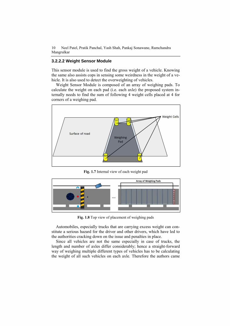
3.2.2.2 Weight Sensor Module
This sensor module is used to find the gross weight of a vehicle. Knowing
the same also assists cops in sensing some weirdness in the weight of a ve-
hicle. It is also used to detect the overweighting of vehicles.
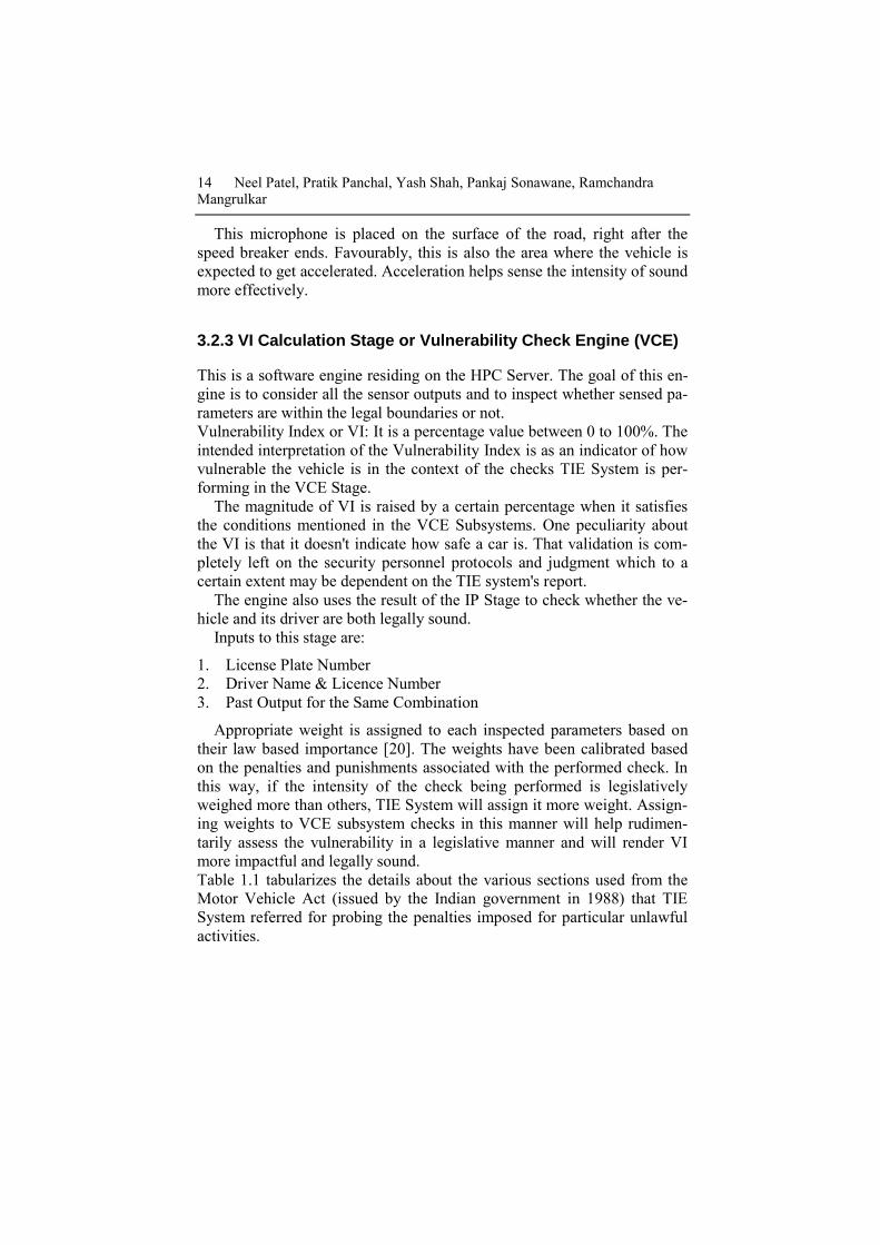
Weight Sensor Module is composed of an array of weighing pads. To
calculate the weight on each pad (i.e. each axle) the proposed system in-
ternally needs to find the sum of following 4 weight cells placed at 4 for
corners of a weighing pad.
Fig. 1.7 Internal view of each weight pad
Fig. 1.8 Top view of placement of weighing pads
Automobiles, especially trucks that are carrying excess weight can con-
stitute a serious hazard for the driver and other drivers, which have led to
the authorities cracking down on the issue and penalties in place.
Since all vehicles are not the same especially in case of trucks, the
length and number of axles differ considerably; hence a straight-forward
way of weighing multiple different types of vehicles has to be calculating
the weight of all such vehicles on each axle. Therefore the authors came

TIE - A Security Mechanism to Protect Motorways: Architecture and Design Principles 11
across a solution to create a set of weighing pads of a fixed length and
breadth which can be placed one after other in an array-like fashion. The
array can be extended linearly along the road lane to a point where it can
accommodate the longest vehicle (horizontally) that is expected to pass by
that road. This approach helps to find the weight of any type of vehicle
from two-wheeler to multi axels truck. Once the weight of each axle is
found then the total weight of the vehicle can be found out by adding all
those weights.
Also, the benefit is every axle is designed to handle some maximum
amount of weight. As a result, if the weight exceeds the system will come
to know and alert the security personnel.
3.2.2.2.1 Mutli-Lane Deployment
Fig. 1.9 Weight sensor setup using Multi-lane deployment concept
The weighing system is placed to weight almost all size of vehicles from
2-wheeler bikes to 5-Axle Trucks and this system is not restricted to the
number of lanes.
Typically at toll roads, there is a dedicated lane for heavy vehicles such
as trucks, buses and light vehicles like personal cars. In such a scenario
where it is certain that a heavy vehicle is not allowed to pass from light
vehicle lane in any circumstances, the total number of weighing pads can
be adjusted to reduce cost. In case where such segregation is not possible
the array of weighing pads can be increased or decreased based on lengths
of the expected vehicles.

12 Neel Patel, Pratik Panchal, Yash Shah, Pankaj Sonawane, Ramchandra Mangrulkar
This concept for Multi-lane deployment of the system to reduce cost is a
niche use and not a compulsion.
3.2.2.3 Vehicle Created Pollution or VCP Sensor Module:
This sensor module will be placed under the road near the vehicle exhaust
area; the position will be 1 to 3 feet before the vehicle detector’s LDR is
placed.
Fig. 1.10 Side view of VCP Sensor Module Setup
Fig. 1.11 Top view of VCP Sensor Module Setup
To make the sensing process effective following arrangement are made:

TIE - A Security Mechanism to Protect Motorways: Architecture and Design Principles 13
- There will be a fan pulling the exhausted air of vehicle which is
placed below the sewer manhole.
- This metal net will be parallel to the road and will be placed on the
surface of the road.
- The air pulled by the fan will directly be thrown on the VCP
Check Sensor which then finds the purity of air throw by any ve-
hicle.
3.2.2.4 Silencer Sound Module:
Every vehicle is assigned some maximum limit on the silencer sound it can
produce [18] [19]. If the sound is beyond that limit, it is illegal to drive that
vehicle. To adapt to the standard method of me measuring the vehicle
sound, some calibration mechanism will have to be used to calculate the
equivalent value of the sound produced from 50 feet away of the vehicle’s
centre.
Fig. 1.12 Top view of placement of microphone
To check the overall sound of the vehicle TIE system uses a micro-
phone. The microphone then calculates the sound intensity rating in deci-
bel. The microphone input is then compared with maximum allowed deci-
bel.
Since the prior mentioned maximum limit is vehicle specific it is
fetched from the vehicle details database after the model is extracted in the
Image Processing Stage. And as a result of this, the comparison of the in-
put intensity and the legal limit are compared and presented to the security
personnel in the Reporting Stage.
14 Neel Patel, Pratik Panchal, Yash Shah, Pankaj Sonawane, Ramchandra Mangrulkar
This microphone is placed on the surface of the road, right after the
speed breaker ends. Favourably, this is also the area where the vehicle is
expected to get accelerated. Acceleration helps sense the intensity of sound
more effectively.
3.2.3 VI Calculation Stage or Vulnerability Check Engine (VCE)
This is a software engine residing on the HPC Server. The goal of this en-
gine is to consider all the sensor outputs and to inspect whether sensed pa-
rameters are within the legal boundaries or not.
Vulnerability Index or VI: It is a percentage value between 0 to 100%. The
intended interpretation of the Vulnerability Index is as an indicator of how
vulnerable the vehicle is in the context of the checks TIE System is per-
forming in the VCE Stage.
The magnitude of VI is raised by a certain percentage when it satisfies
the conditions mentioned in the VCE Subsystems. One peculiarity about
the VI is that it doesn't indicate how safe a car is. That validation is com-
pletely left on the security personnel protocols and judgment which to a
certain extent may be dependent on the TIE system's report.
The engine also uses the result of the IP Stage to check whether the ve-
hicle and its driver are both legally sound.
Inputs to this stage are:
1. License Plate Number
2. Driver Name & Licence Number
3. Past Output for the Same Combination
Appropriate weight is assigned to each inspected parameters based on
their law based importance [20]. The weights have been calibrated based
on the penalties and punishments associated with the performed check. In
this way, if the intensity of the check being performed is legislatively
weighed more than others, TIE System will assign it more weight. Assign-
ing weights to VCE subsystem checks in this manner will help rudimen-
tarily assess the vulnerability in a legislative manner and will render VI
more impactful and legally sound.
Table 1.1 tabularizes the details about the various sections used from the
Motor Vehicle Act (issued by the Indian government in 1988) that TIE
System referred for probing the penalties imposed for particular unlawful
activities.

TIE - A Security Mechanism to Protect Motorways: Architecture and Design Principles 15
Table 1.1 Details of sections used from Motor Vehicle Act for assigning weight-
age to VI calculation parameters
Violation Sce-
nario
Section Penalty and/or Punishment
1st time fine
(Rupees)
Fine change
after 1st time
fined (Ru-
pees)
Imprisonment
(Years)
License Invalid 177 100 300 -
Person with
learner’s license
driving without
any instructor
besides
177 450 500 -
Improper Li-
cense Plate
177 100 300 -
PUC not done 177 100 300 -
Driving without
license
180 1,000 - Up to 3
Silencer sound
is more than le-
gal limit
190 500 - -
Permit of the
vehicle invalid
192 10,000 - Up to 3
Overloaded ve-
hicle
194 2,000 + 1,000
per extra ton of
-

16 Neel Patel, Pratik Panchal, Yash Shah, Pankaj Sonawane, Ramchandra Mangrulkar
load
3.2.3.1 Driving License Checks
This particular subsystem is responsible for conducting a series of checks
related to the vehicle’s license plate. Following cases are considered to be
addressed:
1. Not Found: It means that no license plate was found after processing the
image captured by camera 2.
2. Expired License: The driving license is renewed, yet the driver is driv-
ing the vehicle.
3. Past Criminal: The driver has past criminal cases associated with
him/her.
4. Current Criminal: The driver has ongoing criminal cases associated with
him/her. This also means he/she is on bail or has to be caught.
5. Wrong Use: This case is named as a consistency check in the fig 1.14.
Consistency check here means to check whether the vehicle type detected
from the captured image in the IP stage and category of vehicle(s) the li-
cense is assigned to, are same or not. If they differ it will be a case of
“Wrong Use”.
6. Unlawful Learner: This means that the driver has a learner’s license yet
he doesn’t have a fully licensed driver seated beside him/her.

TIE - A Security Mechanism to Protect Motorways: Architecture and Design Principles 17
Fig. 1.13 Assigned weightage to Driving License Related Checking

18 Neel Patel, Pratik Panchal, Yash Shah, Pankaj Sonawane, Ramchandra Mangrulkar
Fig. 1.14 Sequence of steps executed by Driving License Checks
Subsystem
3.2.3.2 License Plate Related Checks
This particular subsystem is responsible for conducting a series of checks related
to the vehicle’s license plate. This subsystem takes as input the string value of the
license plate number which got extracted in the image processing stage after pro-
cessing the image captured by Camera 2 / Camera in the back barrier.

TIE - A Security Mechanism to Protect Motorways: Architecture and Design Principles 19
Fig. 1.15 Assigned weightage to License Plate Related Checks
Fig. 1.16 Sequence of steps executed by License Plate Checks
Subsystem

20 Neel Patel, Pratik Panchal, Yash Shah, Pankaj Sonawane, Ramchandra Mangrulkar
Following cases are considered to be addressed:
1. Not Found: The license plate string was NULL i.e. No license
plate was found.
2. Damaged: The string that was extracted from the image did not
have proper length and/or had illegal characters on it.
3. Robbed Car: The license plate is of a car which has been reported
robbed by the owner.
4. Wrong Use: The license plate is not used on the vehicle type it is
assigned to.
3.2.4 Reporting Stage
This stage is the last stage of the TIE System Life Cycle. It is meant to
consolidate the results of all the sensed parameter and image processing
based criminal association or history finder. It provides a comprehensive
yet clear cut idea that out of the Parameter. A web-based report is prepared
since that would allow the ability to share the report with the remote offi-
cials also who are doing surveillance tasks.
Fig. 1.17 Sample Report produced by Reporting Stage
Above displayed fig 1.17 is a sample report that shows the basic look
and feel of the output of the Reporting Stage. There are 4 sections in the
generated report as shown in the fig 1.17:
1. Basic Info(Information) Section
TIE - A Security Mechanism to Protect Motorways: Architecture and Design Principles 21
2. VCE Stat(Statistics) Section
3. Vehicle Details Section
4. Feedback Section
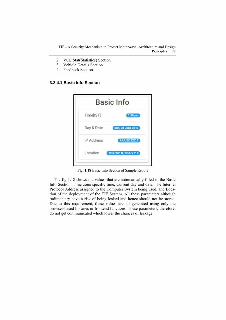
3.2.4.1 Basic Info Section
Fig. 1.18 Basic Info Section of Sample Report
The fig 1.18 shows the values that are automatically filled in the Basic
Info Section. Time zone specific time, Current day and date, The Internet
Protocol Address assigned to the Computer System being used, and Loca-
tion of the deployment of the TIE System. All these parameters although
rudimentary have a risk of being leaked and hence should not be stored.
Due to this requirement, these values are all generated using only the
browser-based libraries or frontend functions. These parameters, therefore,
do not get communicated which lower the chances of leakage.
22 Neel Patel, Pratik Panchal, Yash Shah, Pankaj Sonawane, Ramchandra Mangrulkar
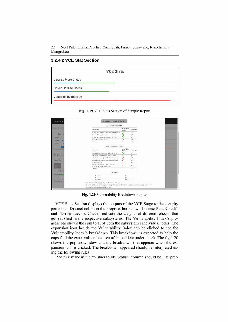
3.2.4.2 VCE Stat Section
Fig. 1.19 VCE Stats Section of Sample Report
Fig. 1.20 Vulnerability Breakdown pop-up
VCE Stats Section displays the outputs of the VCE Stage to the security
personnel. Distinct colors in the progress bar below “License Plate Check”
and “Driver License Check” indicate the weights of different checks that
got satisfied in the respective subsystems. The Vulnerability Index’s pro-
gress bar shows the sum total of both the subsystem's individual totals. The
expansion icon beside the Vulnerability Index can be clicked to see the
Vulnerability Index’s breakdown. This breakdown is expected to help the
cops find the exact vulnerable area of the vehicle under check. The fig 1.20
shows the pop-up window and the breakdown that appears when the ex-
pansion icon is clicked. The breakdown appeared should be interpreted us-
ing the following rules:
1. Red tick mark in the “Vulnerability Status” column should be interpret-

TIE - A Security Mechanism to Protect Motorways: Architecture and Design Principles 23
ed as “the vulnerability check is satisfied” and so the intensity of suspicion
was raised to a certain percentage (i.e. the weight assigned to that individ-
ual check).
2. Green tick mark in the “Vulnerability Status” column should be inter-
preted as the vulnerability check is not satisfied and so the intensity of sus-
picion was not raised by the weight of that particular check.
3. Weights displayed is bold only are considered in the total.
4. The value written as the “Sum total” is the final value of the VI.
Fig. 1.21 Example 1 of breakdown of VI

24 Neel Patel, Pratik Panchal, Yash Shah, Pankaj Sonawane, Ramchandra Mangrulkar
Fig. 1.22 Example 1 of breakdown of VI
For e.g. breakdown like the one shown in fig 1.21 should be interpreted
as there is “No vulnerability detected with respect to the checks per-
formed.” whereas the one alike fig 1.22 should be interpreted as “The
driver’s license not renewed and hence he/she is unlawfully driving the
vehicle.”

TIE - A Security Mechanism to Protect Motorways: Architecture and Design Principles 25
3.2.4.3 Vehicle Details Section
Fig. 1.23 Car Details Section of Sample Report
The car details section contains the subsections as shown in the above
figure 1.23. Values of Vehicle name, company name, model name, license
plate number, VCP Status, the weight of the vehicle are all encompassed in
this section. Also, the difference between the corresponding values is dis-
played. A hover on the photo of the vehicle would enlarge it for viewing if
needed.
3.2.4.4 Feedback Section
Feedback Section is used to take asses the system’s IP Stage and VCE
Stage results. There are two modes that can be used to the give feedback
mainly based on the level of traffic on that road but there can be other fac-
tors which lead to choosing one of them too.

26 Neel Patel, Pratik Panchal, Yash Shah, Pankaj Sonawane, Ramchandra Mangrulkar
Fig. 1.24 Feedback Section of the Sample Report configured in Complete Mode
Fig. 1.25 Feedback Section of the Sample Report configured in Complete Mode

TIE - A Security Mechanism to Protect Motorways: Architecture and Design Principles 27
3.2.4.4.1 Complete Mode
Fig. 1.26 Structure of Feedback Form
This mode of the feedback section is used when there handleable traffic
on the road. This section will take the following inputs from the security
personnel viewing the report:
1. Vehicle ID or Vehicle Identifier: This is the unique identifier
assigned to the vehicle under check. The webpage itself will dy-
namically fill this value into the textbox from the Vehicle ID that
it receives from the microcontroller.
2. Barrier Number: This parameter is used only in case of a secu-
rity check arrangement with multiple barriers. It will indicate the
barrier number where the TIE System is deployed.
3. Comment: It is used to record what appeared as suspicious
about the vehicle. It is expected to largely record those parameters
or aspects related to vehicle and road security that is not examined
by the TIE System. The comments can timely be then checked and
analyzed to enhance TIE System and identify various patterns.
4. Actual VI: This is the most crucial part in the feedback sec-
tion. This part has all the parameters shown in the Vulnerability
Index Breakdown window excluding the (1) “totals” related rows
in the “License Plate Check” and “Driver’s License Check” and
(2) the whole table showing “Sum total” in the last row. Actual VI

28 Neel Patel, Pratik Panchal, Yash Shah, Pankaj Sonawane, Ramchandra Mangrulkar
has high importance because the value of this parameter will train
the IP Stage and VCE Stage to improve their processing. And as a
result of which the system will perform better in subsequent detec-
tions. This training cycling will continue infinite runs of the sys-
tem.
This input of this part is given in the form that gets popped up after
clicking the “Give Feedback” button. The report viewer will have to just
uncheck the parameter that was wrongly identified and then submit the
feedback form.
3.2.4.4.1 Quick Mode
This mode is used to give feedback of the system’s IP Stage and VCE
Stage when there is more traffic or due to any issue, the vehicle passing
speed via the checking zone has to be increased. And the most crucial part
i.e. the Actual VI. All parameters inside the Actual VI will be the same in
both modes.
For ease of giving the feedback all the checkboxes in the Actual VI for
are already checked and hence only the wrongly detected parameter should
be found and unchecked. This subtle strategy would save the time of the
cops viewing the report since they are now freed from the job of going
through the whole form every time they give their feedback.

TIE - A Security Mechanism to Protect Motorways: Architecture and Design Principles 29
Fig. 1.27 Comprehensive diagram of operations performed by all 4 stages

30 Neel Patel, Pratik Panchal, Yash Shah, Pankaj Sonawane, Ramchandra Mangrulkar
Fig. 1.27 presents a collective look at the all the TIE System Stages and
their sequences.
3.3 TIE System Sensors
The authors make use of a set of criteria for selecting sensors that can be
used to extend or scale up the system. These sensors are a subset of tradi-
tional sensors that satisfy the following conditions:
1. The sensor has proper datasheet available which also means it’s offi-
cially produced and is tested & reliable.
2. It can stably operate in the temperature range tuned for the system
based on the region of its deployment.
3. It should be possible to cover it in a way it becomes unnoticeable by
any person other than the ones who have deployed it. Any sensor which
satisfies the following condition is considered a TIE Sensor.
3.3 Major Challenges
3.3.1 Synchronizing All Stages
Timing the processes like Image Capturing, Processing and the sensors
sensing appropriately so as to synchronize them in the time domain. In the
proposed model the time delay of the IP Stage will take more time com-
pared to the Sensing Stage and hence some tasks of this stage are executed
first and a queue gets updated in the local memory of the controllers placed
inside barrier 1 and 2 corresponding to the order of checking the cars.
3.3.1 Dynamic Barrier
The license plate detection algorithm is mainly divided into 2 parts (1)
Finding the license plate from the image and (2) Apply Optical Character
Recognition or OCR on the license plate part of the image. But in reality,
these algorithms usually face a considerable amount of issues in the prior
step. There are quite a few reasons for the same as the shadows, lights, re-
flections appearing on the chassis of the vehicle due to sun light, etc.
Hence to counter the issue introduced in the prior part of the license
plate detection algorithm that is creating uncertainty is eliminated by im-
plementing the concept of dynamic barriers.

TIE - A Security Mechanism to Protect Motorways: Architecture and Design Principles 31
Dynamic barriers are characterized mainly by a vertically movable bar-
rier rod, a controller module, and a circular buffer.
These barriers maintain a circular buffer locally in their controller mod-
ule (which will control the vertical height of the barrier). These circular
buffers store the values of the vertical height at which they have to rise or
fall for the vehicle under check and the next two in the waiting queue. The
barrier 1 and 2 receive the heights of the vehicle’s back number plate and
expected drivers face from the ground level respectively.
Fig. 1.28 Illustration of the Circular Queue working
Deceiving the people inside the vehicles from these dynamic barriers is
done in a quite orchestrated way. The front side barrier or barrier responsi-
ble to capture the image of the driver’s face is not very clearly visible to
the next vehicle that will go under check. On the other hand, the back bar-
rier or barrier that will capture the image of the rear side license plate will
become completely unnoticeable to the vehicle under check. This deceiv-
ing will reduce the chances of suspicion on the process of “Driving Li-
cense Check” and “License Plate Check”.
4 Case Study
Authors saw a huge loss of human lives in the terrorist attack that took
place on 14th Feb 2019 in Pulwama District of India [21]. Pointing out one
of the reasons for the attack to be the removal of 3 barriers from the road
where the incident happened Prof. Amita Singh(Professor of Law, Gov-
ernance and Disaster Studies at Jawaharlal Nehru University) said, “The
RDX filled vehicle could not be checked as the 3 check barriers were re-
moved by Mehbooba Mufti...”[22][23]. The potential correctness of the
statement by Prof. Singh and other parameters e.g. inclinations of certain

32 Neel Patel, Pratik Panchal, Yash Shah, Pankaj Sonawane, Ramchandra Mangrulkar
roads, traffic bottlenecks, etc. that directly or indirectly contribute to the
vulnerability of the roads like the one where the discussed incident hap-
pened. Hence a system that assists the security personnel(s) in tracking the
parameters unusual to the vehicles at the same time being unnoticeable by
the malevolent and criminal minded individual/groups and is feasible to be
implemented can be useful. Such a system would not only leverage the in-
tensity with which certain parameters of the vehicle under check are exam-
ined but also aid in checking those parameters not directly known to the
security personnel(s) or for that matter any individual at their first glance
on the vehicle.
A vehicle-borne improvised explosive device (VBIED), also known as a
truck bomb or car bomb, is an improvised explosive device installed inside
a car or other automobile and then exploded. This very type of bomb was
used in the attack mentioned above and many others [24].
Shielding against a car bomb requires keeping automobiles at a distance
from exposed targets by using metal barriers, checkpoints, roadblocks and
others alike them[25].
The TIE system would assist the security personnel positioned near the
barriers to check either all or just the suspicious vehicles passing by the
barriers. The system would capture the photo of the vehicle and sense the
parameters simultaneously. TIE System will execute all its 4 stages and
would send its report to the computer system of same or other security per-
sonnel. Particularly, the VCE Stage would find the unusualness in those
parameters, assign a vulnerability index to the vehicle & show the results
to the security personnel. This would also help when population of cars
passing by the barriers is large enough the system will help in finding the
ones that need to be thoroughly checked by the security personnel with re-
spect VCE subsystem checks. It would help them to know the magnitude
of parameters which one cannot find manually & feasibly in all circum-
stances.
5 Conclusion
Road security checks currently face 2 major problems (1) high knowability
and (2) unautomated checking. Therefore it becomes crucial to make the
checks in an unnoticeable way so as to deceive the malevolent individuals
or groups to believe there are no clear obstacles that they have to over-
come. The system is made almost unnoticeable by placing the sensors at
unexpected positions on the site. Even if they are constrained to be operat-
ed in a moving manner, the placements are done in a way that ensures they
are deployed and operated in an inconspicuous location and unexpected

TIE - A Security Mechanism to Protect Motorways: Architecture and Design Principles 33
way respectively. The authors have consolidated a system that uses image
processing; embedded system; IoT and web technology jointly to counter
the prior mentioned loopholes in common security checks done currently.
6 Future direction for further extension
A set of concepts and extensions can still be applied to make the system
better in the aspects like reusability of sensors, turnaround time of check-
ing(s), etc. Mentioned below are some of the specific ideas that can be
worked upon to further extend the system:
1. The System can directly cut monetary penalties from the bank ac-
count of the person for the set of checks it satisfies.
2. TIE System Array can be developed which deploys TIE System
clones that can reuse various sensors at the same time check mul-
tiple cars at a time.
3. To add more checks to the Learner’s license checks like an “L”
sticker present.
4. To use Piezoelectricity, solar energy and similar sciences and
technologies to make TIE System as self-sufficient as possible
with respect to power requirements.
5. To integrate mechanisms [26] that balance the tradeoff between
security and efficiency involved in the communication between
the various sensor modules employed.
References
[1] The Road Safety Crisis In India. In: NDTV-Diageo Road To Safety.
https://sites.ndtv.com/roadsafety/video-details-page/the-road-safety-crisis-in-
india-479985/.
[2] Commodity Flow Survey 2017 | Bureau of Transportation Statistics. In:
Bts.gov. https://www.bts.gov/newsroom/commodity-flow-survey-2017. Ac-
cessed 24 Jun 2019
[3] eurostat (2018) Freight transport in the EU-28 modal split based on five
transport modes (% of tonne-kilometres).
[4] Modi highlights road safety, social issues in radio address. In: The Hindu.
https://www.thehindu.com/news/national/mann-ki-baat-pm-speaks-on-road-
safety-social-issues/article7466865.ece.
[5] Tamane, S., Solanki, V. K., & Dey, N. (Eds.). (2017). Privacy and security
policies in big data. IGI Global.
[6] P S (2018) Hard-hitting road safety campaigns that left a mark. In: Social Sa-
mosa. http://www.socialsamosa.com/2018/01/hard-hitting-road-safety-
campaigns-which-has-left-a-mark/.

34 Neel Patel, Pratik Panchal, Yash Shah, Pankaj Sonawane, Ramchandra Mangrulkar
[7] IIRIS Consulting (2018) INDIA RISK REPORT EP49: Road Safety Challeng-
es.
[8] Schaller, A., & Mueller, K. (2009). Motorola's Experiences in Designing the
Internet of Things. International Journal of Ambient Computing and Intelli-
gence (IJACI), 1(1), 75-85.
[9] Overloaded trucks take heavy toll on highways. In: Tribune India News Ser-
vice. https://www.tribuneindia.com/news/himachal/overloaded-trucks-take-
heavy-toll-on-highways/778798.html.
[10] Hu T (2014) A Framework of Truck Overload Intelligent Monitoring System.
In: 2011 Fourth International Symposium on Computational Intelligence and
Design. IEEE, Hangzhou, p 1
[11] Dey N, Wagh S, Mahalle P, Pathan M (2019) Applied Machine Learning for
Smart Data Analysis, 1st ed. Boca Raton
[12] Toll Weigh Motion | Truck Weighing Systems | Vehicles Weighing Stations
India. In: Essaedig.com. http://www.essaedig.com/truck-weigh-in-
motion.php#overview.
[13] Challenges and Overview of License Plate Character Segmentation. Interna-
tional Journal of Computer Sciences International Journal of Computer Sci-
encesand Engineering 3:1.
[14] Smart cameras to detect errant drivers | Noida News - Times of India. In: The
Times of India. https://timesofindia.indiatimes.com/city/noida/smart-cameras-
to-detect-errant-drivers/articleshow/69807281.cms.
[15] Evaluating the use of automated facial recognition technology in major polic-
ing operations. In: Phys.org. https://phys.org/news/2018-11-automated-facial-
recognition-technology-major.html.
[16] Student Seminar Report & Project Report with Presentation (PPT, PDF,
DOC, ZIP) - Profile of jaseela123d. In: Studentbank.in.
https://studentbank.in/author-jaseela123d.
[17] V. Manitha P, S. Anandaraman S, Manikumaran K, Aswathaman K (2017)
Design and development of enhanced road safety mechanism using smart
roads and energy optimized solar street lights. International Conference on
Energy, Communication, Data Analytics and Soft Computing (ICECDS)
[18] MOTORCYCLE NOISE STANDARDS. In: Cga.ct.gov.
https://www.cga.ct.gov/2003/olrdata/tra/rpt/2003-r-0676.htm. Accessed 24
Jun 2019
[19] Vehicle-certification-agency.gov.uk. (2019). Cars and noise. [online] Availa-
ble at: https://www.vehicle-certification-agency.gov.uk/fcb/cars-and-noise.asp
[20]THE MOTOR VEHICLES ACT. In: Tn.gov.in.
http://www.tn.gov.in/sta/Mvact1988.pdf.
[21] Das S (2019) 44 CRPF jawans killed, 70 injured in Pulwama terror attack in
J&K. In: https://www.livemint.com.
https://www.livemint.com/news/india/pulwama-terror-attack-deathtoll-rises-
to-40-jem-claims-responsibility-1550143395449.html.
[22] JNU prof says Mehbooba Mufti ordered removal of barriers that led to Pul-
wama attack; PDP to take legal action. In: The New Indian Express.

TIE - A Security Mechanism to Protect Motorways: Architecture and Design Principles 35
http://www.newindianexpress.com/nation/2019/feb/20/jnu-prof-
saysmehbooba-mufti-ordered-removal-of-barriers-that-led-to-pulwamaattack-
pdp-to-take-leg-1941055.html. Accessed 24 Jun 2019
[23] Prof. Amita Singh (CHAIRPERSON). In: SCDR JNU.
http://scdr.jnu.ac.in/team/prof-amita-singh-pi/. Special Centre of Disaster Re-
search. (2019). Prof. Amita Singh (CHAIRPERSON). [online] Available at:
http://scdr.jnu.ac.in/team/prof-amita-singh-pi/
[24] Jha R (2019) Why car bombs are worrying our forces. In: The Economic
Times. https://economictimes.indiatimes.com/news/defence/why-car-bombs-
are-worrying-our-forces/articleshow/68019980.cms. Accessed 25 Jun 2019
[25] Mitigating the Dangers of Car Bombs. In: Stratfor.
https://worldview.stratfor.com/article/mitigating-dangers-car-bombs.
[26] Kimbahune, V. V., Deshpande, A. V., & Mahalle, P. N. (2017). Lightweight
key management for adaptive addressing in next generation inter-
net. International Journal of Ambient Computing and Intelligence
(IJACI), 8(1), 50-69.