the influence of structural details on the dissipative beh…
TRANSCRIPT

8/8/2019 The influence of structural details on the dissipative beh…
http://slidepdf.com/reader/full/the-influence-of-structural-details-on-the-dissipative-beh 1/6
EUROSTEEL 2008, 3-5 September 2008, Graz, Austria
THE INFLUENCE OF STRUCTURAL DETAILS ON THE
DISSIPATIVE BEHAVIOUR OF BEAM-TO-COLUMN JOINTS
Fabio Iannone, Vincenzo Piluso, Gianvittorio Rizzano
University of Salerno, Faculty of Civil Engineering, Salerno, Italy
INTRODUCTION
The knowledge of the cyclic behaviour of beam-to-column joints has a paramount importance for the seismic
design of moment-resisting steel frames, especially when the dissipation of seismic input energy has to occur
in the joint components. In particular, beam-to-column bolted joints are widely used in practical design for
their simplicity and their ability to provide a variety of structural solutions. In recent years different structural
details have been tested aiming to investigate both to the whole joint behaviour and to basic joint
components.
In order to verify the possibility to develop a component approach to predict the cyclic response of bolted
beam-to-column joints, new experimental tests have been carried out on full scale beam-to-column joints.
Aiming to verify the correct identification of the main dissipative joint components, the experimental test
results are herein presented in terms of both the total cyclic response of the joint and the cyclic response of
each joint component.
1 DESIGN OF DISSIPATIVE JOINTS
Within the experimental program, still in progress, four cyclic tests have been carried out on external steel
beam-to-column bolted joints designed in order to obtain the same bending strength, but varying the weakest
dissipative joint component, representing the dissipative component.
The following tests have been performed:
• Partial strength extended end plate connection having the column web panel in shear as weakest
component [EEP-CYC01];• Partial strength extended end plate connection having the end plate in bending as weakest component
[EEP-CYC02];
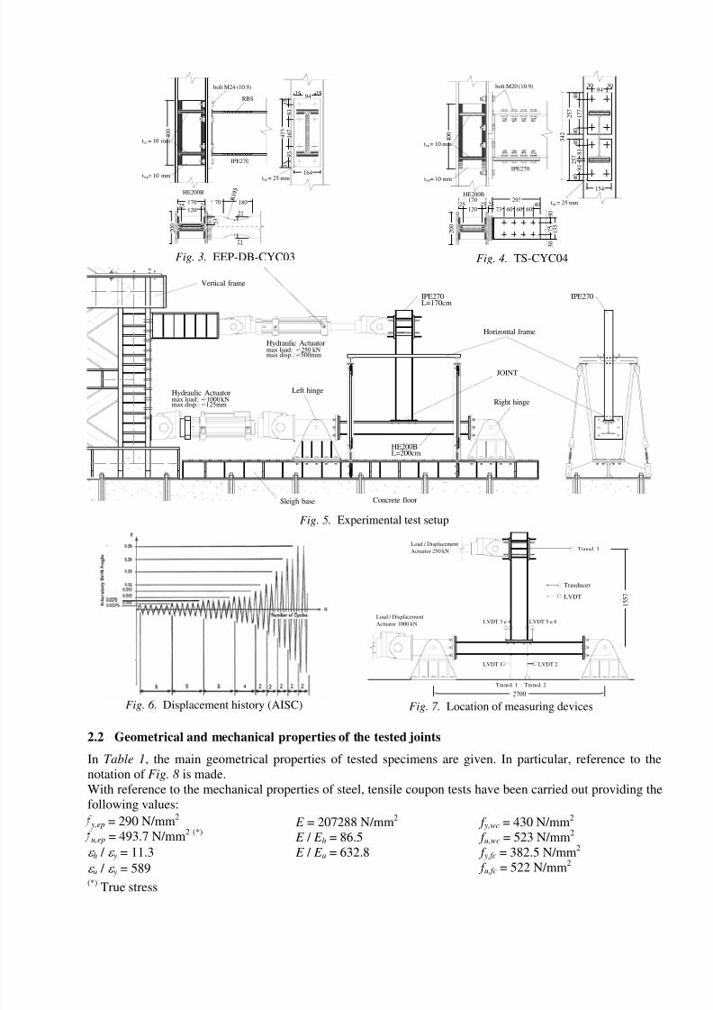
• Full strength extended end plate connection with reduced beam section (dog-bone) [EEP-DB-CYC03];
• T-Stub connection [TS-CYC04].
The specimens have been composed with an HEB200 column (steel grade S355), an IPE270 beam (steel
grade S275), end plates with steel grade S275 and bolts M20 and M24 (class 10.9).
With reference to the EEP-CYC01 joint (Fig. 1), the ultimate moment corresponding to the shear resistance
of the column web is computed as:
≅= t
vcwcu
spu h A f
M 3
,
, 140kN ⋅ m (1)
were Avc is the shear area of the column, ht is the lever arm and f u,wc is ultimate stress of the column web.
The “equivalent T-stub” for the end-plate in bending of EEP-CYC01 joint has been designed by imposing
type-1 dissipative mechanism, according to Eurocode 3, characterized by the formation of plastic hinges at
the bolt axis and at the flange-to-end plate connection and by imposing a 20% overstrength with respect to
the shear panel resistance:
≅⋅
⋅
= t epu
epeff
Tstubu h f m
t b M ,
2
, 1.2 M u,sp (2)
were beff is effective width of the equivalent T-stub assumed equal to width of the end-plate; t ep is the
thickness of the end-plate; m is the distance between the plastic hinges.
Regarding the joint ductility, an ultimate rotation mainly given by the contribution of the shear panel
deformation and of the end-plate deformation, equal to 0.06 rad has been imposed as design condition:
≅+
⋅
⋅= spu
t ep ht
mC ,
2
2γ ϑ 0.06 (3)

8/8/2019 The influence of structural details on the dissipative beh…
http://slidepdf.com/reader/full/the-influence-of-structural-details-on-the-dissipative-beh 2/6
were C is a constant depending on material mechanical properties [1] and assumed equal to 0.195, γ u,sp is the
shear deformation, computed by means of the model of Krawinkler et al [2, 3], corresponding to the ultimate
moment given by Eq. (1).
The EEP-CYC02 joint (Fig. 2) has been designed imposing as weakest component the equivalent T-stub
corresponding to the end-plate in bending. Its design flexural resistance is approximately equal to M u,sp of
EEP-CYC01 joint. In order to maximize the energy dissipation of this joint component, the shear panel has
been strengthened by means of continuity plates and supplementary web plates.
The joint EEP-DB-CYC03 (Fig. 3) was designed by weakening the beam flanges (RBS) so that the plastic
moment achieved at the center of the reduced section zone is equal to:
≅⋅⋅= E y DB pl DB p f W M ,,,
15.1 120 kN ⋅ m (4)
were 1.15 is an amplification factor accounting for strain-hardening [4]; W pl,DB is the plastic section modulus
at minimum section of RBS and f y,E is the expected yield stress of the beam assessed with a coefficient of
overstrength equal to 1.2 with respect to the nominal resistance. Thus, the maximum moment expected at the
face of the column is, according to design, M c ≅ 140kN ⋅ m. The geometry of the reduced section zone has
been designed following the procedure set out in “Steel Tips” [4]. In addition, in order to concentrate the
energy dissipation mainly in the reduced section zone of the beam, the shear panel has been strengthened
with continuity plates and supplementary web plates. In addition, the thickness of the end-plate was designed
aiming to avoid its engage in plastic range.
Finally, the last joint, TS-CYC04 (Fig. 4), has been designed by imposing the following values of strengthand ductility of T-stub elements:
≅⋅
⋅
= t epu
epeff
Tstubu h f m
t b M ,
2
, 140 kN ⋅ m (5) ≅
⋅
⋅=
t ep ht
mC
2
2
ϑ 0.08 (6)
Also in this case the shear panel has been strengthened as in previous joints.
In each of these four cases, the welds between the beam and the end-plate and the welds of supplementary
web plates have been designed as full penetration welds.
HE200B
IPE270
3290
32
4 5
9 3
1 6 7
9 3
4 5
154
4 4 3
t = 20 mm
bolt M20 (10.9)
ep
170
2 0 0
4 4 3
Fig. 1. EEP-CYC01
3094
30
4 0
1 3 4
1 2 6
1 3 4
4 0
4 7 4
154
17025
12025
2 0 0
HE200B
IPE270
bolt M20 (10.9)
t = 20 mmep
t = 10 mmwp
5 3
t = 10 mmcp
4 0 0
Fig. 2. EEP-CYC02
2 EXPERIMENTAL ANALYSIS
2.1 Test setupThe tests have been executed at the structural engineering laboratory of the University of Salerno. Fig. 5
shows the complete scheme of experimental tests. Two hydraulic actuators MTS (model 243) have been used
for the application of the axial load in the column and for the control of the imposed displacement history at
the top of the cantilever beam. Two hinges bolted to a base steel beam anchored to the strong floor allow to
obtain a structural scheme representing the behaviour of external joints as shown in Fig. 5. Finally, an
horizontal frame has been adopted to prevent the lateral buckling of the beam.
In particular, the bottom horizontal actuator (capacity: 1000 kN) has been governed under strength control
applying a costant axial compression in the column equal to 650 kN. The upper actuator (capacity: 250 kN)
has been hooked to the free end of the beam to apply, under displacement control, cyclic displacements. The
amplitude and the number of cycles have been planned according to AISC code for cyclic tests on beam-to-
column joint [5]. Such code proposes displacement history depicted in Fig. 6 . in terms of interstorey drift
angle.
During the tests many parameters have been monitored and acquired: displacements and loads of both the
actuators and the displacements of the different joint components. To this scope 3 position sensors and 6
LVDTs located in different points of the joint, as shown in Fig. 7 , have been adopted.
8/8/2019 The influence of structural details on the dissipative beh…
http://slidepdf.com/reader/full/the-influence-of-structural-details-on-the-dissipative-beh 3/6
70 180
2 2
2 2
3 5
9 3
1 6 7
9 3
3 5
4 2 3
3594
35
164
HE200B
IPE270
bolt M24 (10.9)
t = 25 mmept = 10 mmwp
t = 10 mmcp
4 0 0
RBS
17025
12025
2 0 0
5 3
R 1 9 5
Fig. 3. EEP-DB-CYC03
2 5 7
1 7 7
4 0
2 5 7 8 1
8 1
4 0
4 0
4 0 5
4 2
7 5
3 0
1 3 5
3 0
73 60 60 6040
29317025
12025
2 0 0
25
HE200B
IPE270
bolt M20 (10.9)
t = 10 mm
t = 10 mmcp
4 0 0
wp
t = 25 mmep
3094
30
154
Fig. 4. TS-CYC04
HE200B
IPE270
Hydraulic Actuator
Concrete floorSleigh base
Left hinge
Right hinge
Vertical frame
Horizontal frame
JOINT
IPE270L=170cm
L=200cm
max load: 250 kNmax disp.: 500mm+/-
+/-
Hydraulic Actuatormax load: 1000 kNmax disp.: 125mm+/-
+/-
Fig. 5. Experimental test setup
Fig. 6. Displacement history (AISC)
LVDT 1
Load / Displacement
Actuator 1000 kN
Load / Displacement
Actuator 250 kN Transd. 3
Transd. 1 Transd. 2
LVDT 2
LVDT 3 e 4 LVDT 5 e 6
Trasducer
LVDT
2700
1 5 5 7
Fig. 7. Location of measuring devices
2.2 Geometrical and mechanical properties of the tested joints
In Table 1, the main geometrical properties of tested specimens are given. In particular, reference to the
notation of Fig. 8 is made.
With reference to the mechanical properties of steel, tensile coupon tests have been carried out providing the
following values:
y,ep = 290 N/mm2
u,ep = 493.7 N/mm2 (*)
ε h / ε y = 11.3
ε u / ε y = 589
E = 207288 N/mm2
E / E h = 86.5
E / E u = 632.8
f y,wc = 430 N/mm2
f u,wc = 523 N/mm2
f y,fc = 382.5 N/mm2
f u,fc = 522 N/mm2
(*) True stress

8/8/2019 The influence of structural details on the dissipative beh…
http://slidepdf.com/reader/full/the-influence-of-structural-details-on-the-dissipative-beh 4/6
Table 1. Measured properties of tested joints (mm)
Joint Bolt Bolt
preloadingStiffening bep , hep , tep
e1 , e 2 ,
p1 , p 2 , p 3 HE200B IPE270
EEP
CYC01
8 M20
(10.9)550 N⋅m nothing
153.6
441.0
20.1
30.5, 42.2,
92.6, 94.2, 168.1
hc = 201
bc = 201
t w = 9.2
t f
= 15.3
hb = 268
bb = 134
t w = 6.6
t f
= 10.9
EEP
CYC02
8 M20
(10.9)550 N⋅m
continuity plates
+
supplementary
web plates
156.7
474.4
20.7
31.2, 40.5,
94.3, 133.6, 126.2
hc = 198
bc = 198
t w = 9.2
t f = 15.5
hb = 271
bb = 131
t w = 6.8
t f = 10.7
EEP
DB
CYC03
8 M24
(10.9)800 N⋅m
continuity plates
+
supplementary
web plates
161.0
427.0
25.3
36.0, 33.0,
89.0, 99.0, 163.0
hc = 198
bc = 198
t w = 9.2
t f = 15.5
h RBS = 271
b RBS = 88.8
t w = 6.8
t f = 10.7
TS
CYC04
8 M20
(10.9)550 N⋅m
continuity plates
+
supplementary
web plates
154.0
2×257.0
25.0
30.0, 40.0,
94.0, 177.0
hc = 198
bc = 198
t w = 9.2
t f = 15.5
hb = 271
bb = 131
t w = 6.8
t f = 10.7
2.3 Experimental results
The moment-rotation curves of the four joints are shown in Figs. 9, 10, 11
and 12, while in Fig. 13 the corresponding monotonic envelopes are
compared. It is possible to observe that the four joints exhibit similar
strength as desired, but significant differences occur regarding rotational
capacity and width and stability of hysteresis loops. In particular, the
dissipative behaviour of EEP-CYC01 joint is mainly due to the
contributions of the shear panel and of the equivalent t-stub (Figs. 14 and
16 ), while the column web in compression and tension (Fig. 18) provider a
minor contribution. In case of EEP-CYC02 and TS-CYC04 joints, the
dissipative behaviour is essentially due to the equivalent t-stubs only(comparision among the Figs. 15 and 17 ) which are also responsible of
some pinching.
Hysteretic Curve M-θ EEP-CYC 01
-250000
-200000
-150000
-100000
-50000
0
50000
100000
150000
200000
250000
-0,100 -0,075 -0,050 -0,025 0,000 0,025 0,050 0,075 0,100
Joint Rotation [rad]
M o m e n t [ k N · m m ]
Nodal M-rot
Envelope
Mmax = 181479 kN·mm
Mmin = -200894 kN·mm
Fig. 9. Moment-rotation of EEP-CYC01
Hysteretic Curve M-θ EEP-CYC 02
-250000
-200000
-150000
-100000
-50000
0
50000
100000
150000
200000
250000
-0,100 -0,075 -0,050 -0,025 0,000 0,025 0,050 0,075 0,100
Joint Rotation [rad]
M o m e n t [ k N · m m ]
Nodal M-rot
Envelope
Mmax = 188456 kN·mm
Mmin = -198216 kN·mm
Fig. 10. Moment-rotation of EEP-CYC02
Hysteretic Curve M-θ EEP-DB-CYC 03
-250000
-200000
-150000
-100000
-50000
0
50000
100000
150000
200000
250000
-0,100 -0,075 -0,050 -0,025 0,000 0,025 0,050 0,075 0,100
Joint Rotation [rad]
M o m e n t [ k N · m m ]
Nodal M-rot
Envelope
Mmax = 198499 kN·mm
Mmin = -206503 kN·mm
Fig. 11. Moment-rotation of EEP-DB-CYC03
Hysteretic Curve M-θ TS-CYC 04
-250000
-200000
-150000
-100000
-50000
0
50000
100000
150000
200000
250000
-0,100 -0,075 -0,050 -0,025 0,000 0,025 0,050 0,075 0,100
Joint Rotation [rad]
M o m e n t [ k N · m m ]
Nodal M-rot
Envelope
Mmax = 186299 kN·mm
Mmin = -197472 kN·mm
Fig. 12. Moment-rotation of TS-CYC04
tep bep
h e p
p1
e1 e1
e 2
e 2
p 2
p 2
p 3
Fig. 8. Bolts and end-plate

8/8/2019 The influence of structural details on the dissipative beh…
http://slidepdf.com/reader/full/the-influence-of-structural-details-on-the-dissipative-beh 5/6
The contribution of the column web in compression-
tension is negligible for last three joints (Fig. 19). In
EEP-DB-CYC03 joint, as expected, the plastic
rotation supply has entirely offered by the weakened
zone of the beam in bending, being negligible the
contribution of all the other components. Regarding
the failure modes, the brittle fracture of welds
between the beam flanges and the end-plate caused
sudden collapse of EEP-CYC01 joint at about 0.07
rad (Fig. 9). Conversely, failure made of EEP-CYC02
was due to low-cycle fatigue of the end-plate leading
to complete fracture of the heat affected zone at the
welded connection to the flanges of the beam, with a
quick degrade of strength at about 0.04 rad.
Monotonic envelopes
-250000
-200000
-150000
-100000
-50000
0
50000
100000
150000
200000
250000
-0,100 -0,075 -0,050 -0,025 0,000 0,025 0,050 0,075 0,100
Joint Rotation [rad]
M o m e n t [ k N · m m ]
Envelope EEP-CYC1
Envelope EEP-CYC2
Envelope EEP-DB-CYC3
Envelope TS-CYC4
Fig. 13. Moment-rotation envelopes
In case of EEP-DB-CYC03 joint, the degrade of strength is due to local buckling of beam flanges. Finally,
the collapse of TS-CYC04 joint was due to the fracture of the T-stub flanges resulting from low-cycle
fatigue. The measured displacements deal with both the overall behaviour of the joints and their components,
so that it is possible to outline the contribution of each component to the joint energy dissipation. During
EEP-CYC01 test the formation of yield lines at 45° inside the panel zone has been observed since the earlycycles, while the plastic engagement of the end-plate has been evident only in an advanced phase of the test.
Fig. 20 shows that dissipation is mainly located in the shear panel. However, the contribution due to the
equivalent T-stubs is not negligible. Conversely, the column web in compression-tension is not significantly
engaged. It is important to underline that Fig. 20 points out that the external work developed in the
experimental test can be obtained as the sum of the energy dissipated by each joint component. Analogous
considerations are possible for tests EEP-CYC02 and TS-CYC04 where only the plastic engagement of the
T-stubs has been observed (Figs. 21 and 23). Finally, in EPP-DB-CYC03 test the concentration of plastic
deformations in the weakend portion of beam occurs. The dissipated energy is almost completely due to the
dog-bone while the energy dissipated by the other joint components is not significant (Fig. 22).
4 CONCLUSIONS
On the base of the experimental results obtained in the present work, the possibility to extend the component
approach to predict the cyclic behaviour of beam-to-column joints appears feasible, because experimental
evidence shows that the total energy dissipated by beam-to-column joints can be obtained as the sum of the
energies dissipated by each component, provided that the joint components are properly identified and
modelled.
Hysteretic Curve M-γ EEP-CYC 01
-250000
-200000
-150000
-100000
-50000
0
50000
100000
150000
200000
250000
-0 ,0 5 - 0,0 4 -0 ,0 3 - 0,0 2 - 0,0 1 0 ,0 0 0 ,0 1 0,0 2 0 ,0 3 0 ,0 4 0 ,0 5
γ [rad]
M o m e n t [ k N · m ]
Shear Panel
Fig. 14. Shear panel of EEP-CYC01
Hysteretic Curve M-γ EEP-CYC 02
-250000
-200000
-150000
-100000
-50000
0
50000
100000
150000
200000
250000
- 0 ,0 05 - 0, 00 4 - 0,0 03 - 0, 00 2 - 0, 00 1 0 ,0 00 0 ,0 01 0 ,0 02 0 ,0 03 0 ,0 04 0 ,0 05
γ [rad]
M
o m e n t [ k N x m m ]
Shear Panel
Fig. 15. Shear panel of EEP-CYC02
Hysteretic Curve F-δ EEP-CYC 01
-800
-600
-400
-200
0
200
400
600
800
-1 0 1 2 3 4 5 6 7 8 9 1 0 11 12 13 14 15 16
Displacement [mm]
F o r c e [ k N ]
T-Stub Sx
Fig. 16. Left equivalent T-stub of EEP-CYC01
Hysteretic Curve F-δ EEP-CYC02
-800
-600
-400
-200
0
200
400
600
800
-1 0 1 2 3 4 5 6 7 8 9 10 11 12 13 14 15 16
Displacement [mm]
F o r c e [ k N ]
T-Stub Sx
Fig. 17. Left equivalent T-stub of EEP-CYC02

8/8/2019 The influence of structural details on the dissipative beh…
http://slidepdf.com/reader/full/the-influence-of-structural-details-on-the-dissipative-beh 6/6
Hysteretic Curve F-δ EEP-CYC 01
-800
-600
-400
-200
0
200
400
600
800
-4 -3 -2 -1 0 1 2 3 4
Displacement [mm]
F o r c e [ k N ]
Panel T-C Sx
Fig. 18. Column web of EEP-CYC01
Hysteretic Curve F-δ EEP-DB-CYC03
-1000
-800
-600
-400
-200
0
200
400
600
800
-4 -3 -2 -1 0 1 2 3 4
Displacement [mm]
F o r c e [ k N ]
Panel T-C Sx
Fig. 19. Column web of EEP-DB-CYC03
Energy dissipation EEP-CYC 01
0
50000
100000
150000
200000
250000
20 25 30 35 40
n° cycles
E
n e r g y [ k N · m m ]
Node
Shear Panel
T-Stub EP Sx
T-Stub EP Dx
PAN Sx
PAN Dx
SUM Comp.
Fig. 20. Energy dissipation of EEP-CYC01
Energy dissipation EEP-CYC 02
0
10000
20000
30000
40000
50000
60000
20 25 30 35
n° cycles
E
n e r g y [ k N · m m ]
Node
Shear Panel
T-Stub EP Sx
T-Stub EP Dx
PAN Sx
PAN Dx
SUM Comp.
Fig. 21. Energy dissipation of EEP-CYC02
Energy dissipation EEP-DB-CYC 03
0
50000
100000
150000
200000
250000
20 25 30 35 40
n° cycles
E n e r g y
[ k N · m m ]
Node
Shear Panel
T-Stub EP Sx
T-Stub EP Dx
PAN Sx
PAN Dx
SUM Comp.
Fig. 22. Energy dissipation of EEP-DB-CYC03
Energy dissipation TS-CYC 04
0
20000
40000
60000
80000
100000
120000
140000
160000
180000
200000
20 25 30 35 40
n° cycles
E n e r g y
[ k N · m m ]
Node
Shear Panel
T-Stub EP Sx
T-Stub EP Dx
PAN Sx
PAN Dx
SUM Comp.
Fig. 23. Energy dissipation of TS-CYC04
REFERENCES
[1] C. Faella, V. Piluso, G Rizzano (2000): “Structural Steel Semirigid Connections”, CRC Press, Florida,
ISBN 0-8493-7433-2.
[2] H. Krawinkler, V.V. Bertero, E.P. Popov (1971): “Inelastic Behaviour of Steel Beam-to-ColumnSubassemblages”, Report UCB/EERC-71/7 , Earthquake Engineering Recent Center, Univ. of
California, Berkley.
[3] H. Krawinkler, V.V. bertero, E.P. Popov (1973): “Further Studies on Seismic Behaviour of Steel
Beam-Column Subassemblages”, Report UCB/EERC-73/27 , Earthquake Engineering Recent Center,
Univ. of California, Berkley.
[4] K. S. Moore, J. O. Malley, M. D. Engelhardt, (1999): “Design of Reduced Beam Section (RBS)
Moment Frame Connections”, Steel TIPS, August, Structural Steel Educational Council
[5] AISC (2202):”Seismic Provisions for Structural Steel Buildings”, ANSI/AISC 341-02, American
Institute of Steel Construction