the impact of tilt and inflow angle on ground based lidar wind · pdf file ·...
TRANSCRIPT

THE IMPACT OF TILT AND INFLOW ANGLE ON GROUND BASED LIDAR WIND MEASUREMENTS
Muhammad MangatF, Edward Burin des Roziers, John MedleyP, Mark Pitter,
Will Barker, Michael Harris
(1) : Muhammad Mangat: ZephIR lidar, The Old Barns, Fairoaks Farm, Hollybush, Ledbury, England, HR8 1EU.
Muhammad.mangat@ zephirlidar.com, Phone : +44 (0) 1531 650 757, Fax : +44 (0) 1644 430009
Summary A high degree of accuracy in wind measurements is crucial to wind resource assessment. Hence, it is vital that any sources of uncertainty are quantified. An investigation of the impact on horizontal wind speed measurements of a static tilt has been performed with a ZephIR 300
lidar at the UK remote sensing test site (Pershore). Static tilts up to 10⁰ from the horizontal were investigated using ten minute averaged data and results compared to theoretical modeling. In addition, the tests have also been used to verify measurements of inflow angle, which is relevant for turbine siting studies. These results demonstrate the ability of ZephIR 300 to measure inflow angle with high accuracy (sub 1-degree) over a wide range of values.

1 Introduction
Use of lidar technology has been increasing in the wind industry since its introduction in 2003. Ground-based lidars are very valuable in replacing more conventional technology, such as cup anemometers mounted on lattice masts, for a number of reasons, including mobility and lack of prior planning permission requirements. This applies equally to pre-development, resource assessment and post-development stages in the operational performance of the wind farm.
Their use in industry falls in line with increasing demands to build larger wind turbines and wind farms both onshore and offshore to meet the energy demand. Wind measurements at the increasing hub heights become increasingly costly with traditional masts yet is possible with ground based lidars at no extra cost.
Ground-based lidar is a valuable tool for providing finance-grade wind resource data. Hence, it is crucial that any sources of uncertainty are identified and quantified. One such is the effect of an inadvertent tilt of the lidar unit, as can be caused by settling of the ground on which it sits, or from slowly changing tilts when mounted on a floating offshore platform. In purely horizontal wind flow, introduction of a tilt angle beyond a certain degree may induce a negative bias in the horizontal wind speed. Understanding the magnitude of the bias determines the maximum tilt which can be tolerated.
Knowledge of the inflow angle for a given site is required for selecting the appropriate turbine for that site. As a secondary objective of this study, a tilted lidar provides the means to assess how well lidars measure inflow angle. By tilting a lidar on a site with known horizontal flow, the lidar will report an observed inflow angle which is wind direction dependent. Observed inflow angles are compared to predicted results to assess the accuracy of lidar inflow angle measurements.
2 Test Site
The test was conducted at the UK remote sensing test site (Pershore) operated by ZephIR. The site comprises of an IEC compliant [1] 91m tall mast. The mast has four pairs of anemometers at 20m, 45m, 70m and 91m and two direction vanes at 88m and 43m. One of the anemometers at 91m is a Metek USA-1 3D sonic anemometer. All instruments are classified as Class A. Mast shadow filters are applied for top two heights based on direction from the 88m vane and lower two heights based on direction from the 43m vane. The terrain at the site is flat and covered with sparse low growing vegetation. A full analysis of the site has been taken into account [2].
2.1 ZephIR 300
ZephIR 300 is a monostatic, continuous wave (CW) Doppler lidar capable of measuring wind speeds and directions at up to 10 user-selected heights [3]. As a vertical-azimuth scanning lidar, ZephIR 300 interrogates each measurement height sequentially at a rate of 1Hz, building up a wind profile up to heights of 200m. During each scan, the ZephIR collects 50 line-of-sight (LOS) speeds.
3 Effects of Static Tilt
In the absence of tilt, the circular scan disk of the lidar is horizontal and the emitted beam forms a constant angle ( ) from the vertical. When the lidar is tilted, becomes a function of the scan azimuth angle, , which leads to a modulation of the measured LOS wind speed. In purely horizontal wind flow, this mimics the effect of wind with a non-zero inflow angle on a non-tilted lidar (Figure 1).
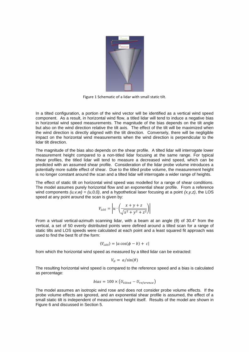
Figure 1 Schematic of a lidar with small static tilt.
In a tilted configuration, a portion of the wind vector will be identified as a vertical wind speed component. As a result, in horizontal wind flow, a titled lidar will tend to induce a negative bias in horizontal wind speed measurements. The magnitude of the bias depends on the tilt angle but also on the wind direction relative the tilt axis. The effect of the tilt will be maximized when the wind direction is directly aligned with the tilt direction. Conversely, there will be negligible impact on the horizontal wind measurements when the wind direction is perpendicular to the lidar tilt direction.
The magnitude of the bias also depends on the shear profile. A tilted lidar will interrogate lower measurement height compared to a non-titled lidar focusing at the same range. For typical shear profiles, the titled lidar will tend to measure a decreased wind speed, which can be predicted with an assumed shear profile. Consideration of the lidar probe volume introduces a potentially more subtle effect of shear. Due to the titled probe volume, the measurement height is no longer constant around the scan and a tilted lidar will interrogate a wider range of heights.
The effect of static tilt on horizontal wind speed was modelled for a range of shear conditions. The model assumes purely horizontal flow and an exponential shear profile. From a reference wind components (u,v,w) = (u,0,0), and a hypothetical laser focusing at a point (x,y,z), the LOS speed at any point around the scan is given by:
| (
√ )|
From a virtual vertical-azimuth scanning lidar, with a beam at an angle ( ) of 30.4° from the
vertical, a set of 50 evenly distributed points were defined around a tilted scan for a range of static tilts and LOS speeds were calculated at each point and a least squared fit approach was used to find the best fit of the form:
⟨ ⟩ | ( ) |
from which the horizontal wind speed as measured by a tilted lidar can be extracted:
( )⁄
The resulting horizontal wind speed is compared to the reference speed and a bias is calculated as percentage:
( )
The model assumes an isotropic wind rose and does not consider probe volume effects. If the probe volume effects are ignored, and an exponential shear profile is assumed, the effect of a small static tilt is independent of measurement height itself. Results of the model are shown in Figure 6 and discussed in Section 5.

4 Test Procedure
Three ZephIR 300 units were placed side by side and against the 91m Pershore met mast. Prior to the tilt trial, each of the ZephIRs was installed with tilt to validate their performance. The three ZephIR units were then tilted by , and from the horizontal. Tilt angles were measured using a digital inclinometer placed on the underside of the unit. Direction of the tilt is determined from the ZephIR base geometry. The ZephIR’s legs form an equilateral triangular base, with vertices at , and relative to the unit orientation. For simplicity, the ZephIRs were titled by adjusting only a single leg (Figure 2). To ensure a full coverage of wind directions relative to the tilt axis, the tilt direction was altered once mid-trial for each tilted unit. Averaged (10-min) wind measurements were collected from the three units and the mast for concurrent periods.
Figure 2 Tilted ZephIR graphical orientation
Table 1 Tilt Configuration
Start End Unit Tilt/ Degrees
Tilt Axis/ Degrees
Tilt Direction/ Degrees
05/01/2014 29/01/2014 1 0 N/A N/A
05/01/2014 04/02/2014 2 5 30 - 210 300
04/02/2014 09/03/2014 2 5 150 - 330 60
05/01/2014 04/02/2014 3 10 30 - 210 300
04/02/2014 09/03/2014 3 10 150 - 330 60
Table 1 Trial dates, tilt angles and tilt orientation for the test.

5 Horizontal Wind Speed
ZephIR performance was assessed in terms of the forced-fit gradients of the 10-minute horizontal wind speeds (>3m/s) with concurrent collocated mast wind speed. Coefficients of determination (R
2) are also reported as a measure of precision. A comparison of the 91m
horizontal wind speeds of the test lidars and the reference mast are presented in Figures 3-5. The results show the insensitivity of the ZephIR to a small static tilt. For static tilts of , the observed gradients at all heights tested were within 0.3% of unity, well within the accuracy of traditional cup anemometers. For a tilt of , ZephIRs demonstrate a measurable negative bias on the order of 0.9% at all heights. It should be noted that all of the tested units showed extremely high R
2.
Figure 3 ZephIR Vs Mast correlation at 91m
Figure 4 ZephIR Vs Mast correlation at 91m Figure 5 ZephIR Vs Mast correlation at 91m
Results of the wind speed correlation for all the heights compared are provided in Table 2. For all ZephIRs, the gradients from the 4 heights are within 0.5% of each other showing that the effect of a tilt is independent of measurement height.

Table 2 ZephIR – Mast Correlation Results
Table 2. Gradients and coefficients of determination from 10min horizontal wind speed compared from tilted ZephIRs and a collocated mast.
Furthermore, the observed biases of the tilted ZephIRs are in close agreement with the modeled results. A family of curves describing the expected bias from a tilted lidar for a given shear profile is shown in Figure 6. The observed biases from the tilted ZephIRs were estimated as a percentage deviation of the gradients from unity and are displayed along with modeled results. Shear exponent coefficients of 0.1 – 0.2 are typical for the Pershore site.
Figure 6 A family of model-generated curves showing the combined effect of static tilt and shear on (Z300) measurements. Actual observations of bias at 91m from tilted lidars are displayed for
comparison.
6 Inflow Angle
We have additionally used the results of these experiments to demonstrate the ability of ZephIR 300 to measure correctly the inflow angle of the wind field. Placing the lidar on a tilt effectively mimics the impact of an inflow angle, but in a controllable manner that allows comparison of theory with experimental results.
Hence, the effective inflow angle observed by a tilted lidar can be predicted if the true inflow angle with respect to ground is known. The distribution of true inflow angles at the Pershore site as measured by a sonic 3D anemometer mounted at 91m (Figure 7) shows that typical

conditions fall within ±1° of zero inflow angle. These conditions are consistent with the very flat
nature of the test site, and agree with our assumption of a true horizontal wind flow.
Figure 7 The distribution of true inflow angles observed by the 3D sonic anemometer at 91m for the Pershore test site.
The inflow angle observed by the tilted ZephIR are plotted as a function of wind direction relative to the tilt directions. The results in Figures 8 and 9 are both at 91m height, for tilt angles of 5 and 10 degrees respectively, while figures 10 and 11 show the corresponding results for height 70m. The observed inflow angle is largest when the wind direction is aligned with the tilt direction. The variation of the measured inflow angle can be shown to exhibit a sine function variation, and this theoretical prediction is plotted as the red curves on the graphs below. The measured 10-minute values (in blue) follow these curves closely for a wide range of wind directions. The mean measured values have been calculated in 10-degree sector bins, and these are plotted as the black points. Deviations of these points from the theoretical curve are of order 1 degree or less, comparable to the magnitude of the actual inflow observed by the sonic, plotted in figure 6. From these results we conclude that ZephIR 300 is capable of measuring inflow angle to better than 1 degree.

Figure 7 ZephIR observed inflow angle at 91m with tilt of
Figure 8 ZephIR observed inflow angle at 91m with tilt of
Figure 9 ZephIR observed inflow angle at 70m with tilt of
Figure 10 ZephIR observed inflow angle at 70m with tilt of
7 Conclusion
This study has shown that horizontal wind speeds measured by ZephIR 300 is very insensitive
to static tilts up to 5⁰ in terms of both accuracy and precision. The forced fit gradients of the 5⁰ tilted unit compared to a reference mast was less than 0.3%. Static tilts of 10⁰ in flat terrain result in a measureable negative bias, which is however still within typical cup uncertainties. With accurate tilt sensors on the lidar, there is potential to correct for static tilts and remove the uncertainty associated with the tilt. Tilting a lidar resulted in no measureable degradation in R
2,
compared to a non-tilted lidar.
In addition, by tilting the lidar to mimic an inflow angle, excellent agreement has been obtained between measurements and modelled inflow angle. These are important results in light of increased use of lidar for both onshore and off-shore wind resource assessment and should serve to increase user confidence that ZephIR 300 is capable of delivering bankable data in a wide range of deployments.

References
[1] IEC 61400-12-1 International Standard. Part 12-1 : Power performance measurements of electricity producing wind turbines. Edition 1.0 2005-12, International Electrotechnical Commission.
[2] W. Barker, M. Harris et. al., Lidar Turbulence Measurements for Wind Farm Energy Yield Analysis, Natural Power/ ZephIR Ltd., EWEA 2013. [3] C J Karlsson, F Å A Olsson, D Letalick & M Harris, All-fiber multifunction CW 1.55 micron coherent laser radar for range, speed, vibration and wind measurements, Applied Optics 39 3716-3726 (2000)