the high-level trigger of the alice experiment
DESCRIPTION
The High-Level Trigger of the ALICE Experiment. Heinz Tilsner Kirchhoff-Institut für Physik Universität Heidelberg International Europhysics Conference on High-Energy Physics 2003 Aachen. Further information: http://www.ti.uni-hd.de/HLT. Content. - PowerPoint PPT PresentationTRANSCRIPT

The High-Level Trigger of theALICE Experiment
Heinz TilsnerKirchhoff-Institut für Physik
Universität Heidelberg
International Europhysics Conference on High-Energy Physics 2003 Aachen
Further information: http://www.ti.uni-hd.de/HLT

Content
•Physics Applications of the High-Level Trigger
•Online Pattern Recognition and Event Reconstruction
•Computing Infrastructure

Physics Applications I
Open-charm trigger:
• Momentum filter (low pt cut)
• Examination of the event topology
Jet-Trigger:
• Online jet trigger from TPC inspection of central Pb-Pb collisions at 200 Hz
• Cone jet-finder algorithm for online
Pile-up removal:
• Reconstruction of all tracks in the TPC• Reconstruction of the event vertex• Pile-up reduction by using a cut on impact parameter of
tracks• Data reduction about a factor 5

Physics Applications II
e+e- Trigger:
TRD TPC
1) TRD-TPC track matching and precise tracking of e+e— candidates
2) PID and inv. mass analysis of e+e—pairs
HLT system
Di-Muon Trigger:
Using information of the di-muon spectrometers to determine the transversal momentum
pt cut
HLT reduces event rate about a factor of 10 by:
• combining TRD tracklets with TPC and ITS tracking• adding PID rejection power from TPC dE/dx
Reconstructing J/Ψ and Y by their leptonic decays into e+e- pairs

HLT Functionality
local pattern recognition –
detector specific
local pattern recognition –
detector specific
global pattern recognition
eventreconstruction
trigger decisionresulting trigger decision is based on fully analyzed and reconstructed events
local pattern recognition (detector specific):
• cluster finder
• tracklets
global pattern recognition:
• e.g. global tracking in TPC
Time budget:Online analysis needs 12s for one eventwith dN/dY=4000or2400 CPUs at event rate of 200 Hz
parallel processing on PC cluster

Fast Pattern Recognition
FPGA co-processor:
• releases CPU resources of host CPU• online Hough Transform is essential for tracking
in dense environment
low multiplicity events
sequential feature extraction on space points• cluster finder• track follower
high multiplicity events
iterative feature extraction on raw data:• tracklet finder (Hough transform)• parallel cluster evaluation

Low Occupancy
D eco de r F IF O (lpm ) Me rge rP o s t
P roce ss ing
R A M (lpm )
T es tb ench
T op s truc ture
se qse q
F ile :C harg es
F ile :C lus te rs
1. Cluster finder (FPGA):• cluster finding• centroid calculation• deconvolution
2. Tracking (host CPU)
Hardware implementation:
Decoder:• decoding incoming ADC sequences (ALTRO list)• calculating charge, sequence charge, and time of
a sequence
Merger:merges sequences of adjacent pads to clusters
Verification of functionality:C++ code = VHDL code
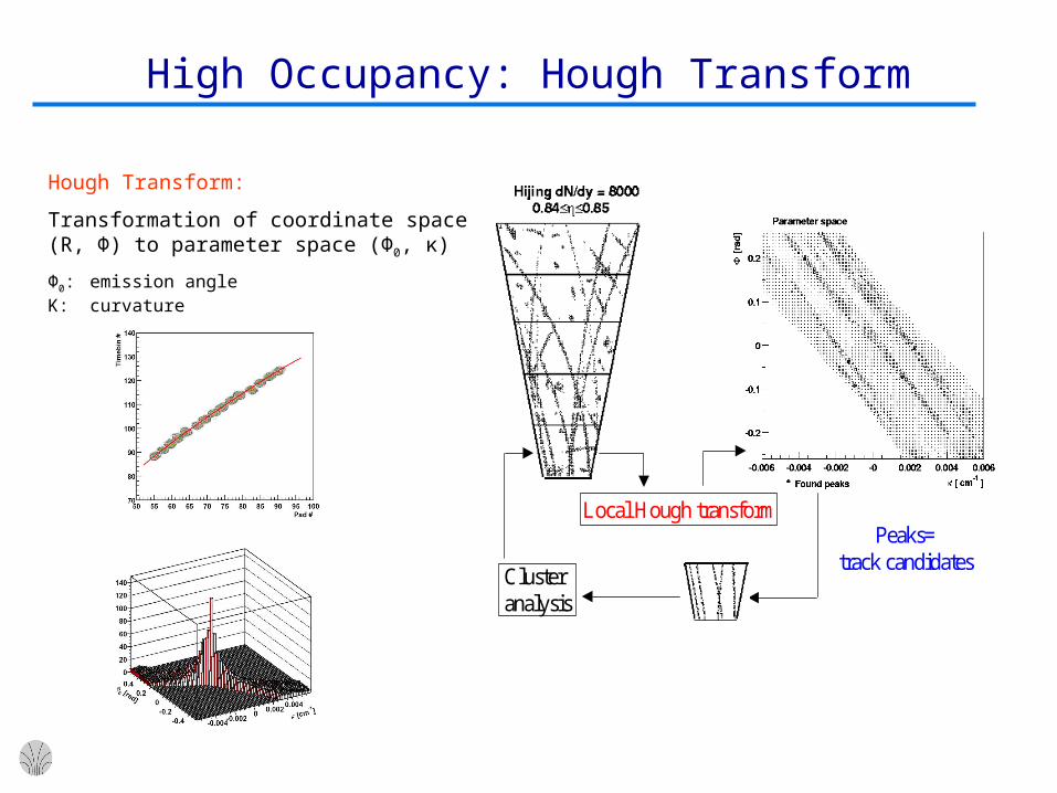
High Occupancy: Hough Transform
Local Hough transform
Clusteranalysis
Peaks=track candidates
Hough Transform:
Transformation of coordinate space (R, Φ) to parameter space (Φ0, κ)
Φ0: emission angleΚ: curvature

Hough Transform in FPGA Co-Processor
Data FormatDecoder
Data FormatDecoder
XYZTransformer
XYZTransformer
ABETransformer
ABETransformer
Back Linked List TPC coordinates Local coordinates Parameter Space (ALTRO sequences) (Padrow, Pad, Time) (X, Y, Z) (A,B,E) (k,phi,eta-index)
Detector Data LinkDetector Data Link Histogram 1Histogram 1
.
.
.
.
.
.
Histogram N-1Histogram N-1
Histogram NHistogram N
Histogram 2
ADC count FindMaxima
FindMaxima10-to-8 Bit
Converter
10-to-8 BitConverter
Behavioral (VHDL) model of Hough Transform simulated and compared with software
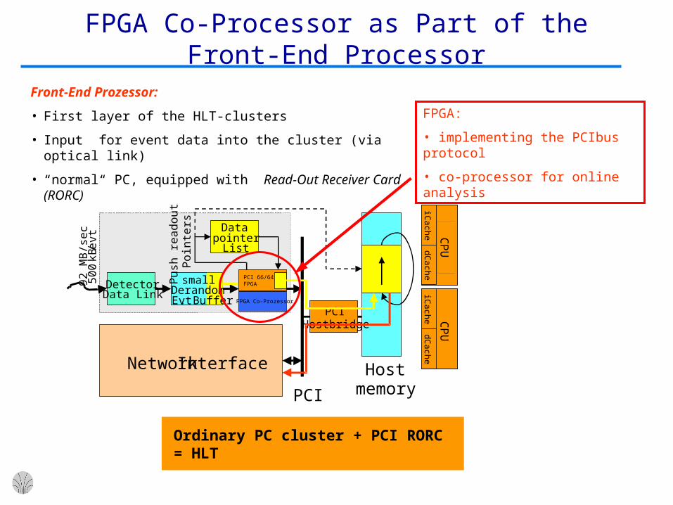
FPGA Co-Processor as Part of the Front-End Processor
Front-End Prozessor:
• First layer of the HLT-clusters
• Input for event data into the cluster (via optical link)
• “normal“ PC, equipped with Read-Out Receiver Card (RORC)
Ordinary PC cluster + PCI RORC = HLT
DetectorData Link
Datapointer
List
Pus
h re
adou
t P
oint
ers
PCI
Hostmemory
PCIHostbridge
smallDerandom.Evt. Buffer
CP
U
iCache
dCache
CP
U
iCache
dCache
CP
U
iCache
dCache
CP
U
iCache
dCache92
MB
/sec
500
kB/ e
vt
NetworkInterface
FPGA Co-Prozessor
PCI 66/64FPGA
FPGA:
• implementing the PCIbus protocol
• co-processor for online analysis

Data Volume + Event Rates
front-endelectronics
Event Building
High Level Trigger System
Permanent Storage System
4.56 TBytes/sec
FEP FEP FEP FEP FEP
216 DDL
TPC Detector364 MB/event
80 µs readout time200 … 1000 Hz L2A
front-endelectronics
15 TBytes/sec
TRD Detector30 MB/event
2 µs readout time1000 Hz L2A
18 DDL
FEP FEP
front-endelectronics
diMuon Detector500 kB/event
1µs readout time1000 Hz L2A
10 DDL
FEP
front-endelectronics
ITS, spare
1000 Hz L2A
20 GBytes/sec
< 1.25 GBytes/sec
< 1.25 GBytes/sec

HLT Cluster Setup
CP
U: 40%
CP
U: 40%
EM/ES
PM PM
EM
EM/ES
PM PM
EM
EM/ES
PM PM
EM
EM/ES
PM PM
EM
EM/ES
PM PM
EM
EM/ES
PM PM
EM
TT
Patches
-
1 65432
CF
AU
FP
CP
U: 100%
CF
AU
FP
CF
AU
FP
CF
AU
FP
CF
AU
FP
CF
AU
FP
1 65432
CF
AU
FP
CP
U: 100%
CF
AU
FP
CF
AU
FP
CF
AU
FP
CF
AU
FP
CF
AU
FP
T T
EM
T T
EM
T T
EM
T T
EM
T T
EM
T T
EM
T T
EM
T T
EM
T T
EM
CP
U: 50
-60%T T
EM
T T
EM
T T
EM
T T
EM
T T
EM
T T
EM
T T
EM
T T
EM
T T
EM
T T
EM
T T
EM
T T
EM
T T
EM
T T
EM
T T
EM
T T
EM
T T
EM
T T
EM
CP
U: 50
-60%
CP
U: 50
-60%
EG/ES
SM SM
HL
0
EM/ES
PM PM
EM
EM/ES
PM PM
EM
HL
1H
L 2
HL
3
FPFP
CFCF
AUAU
Event Merger
Cluster Finder
ADC Unpacker
File Publisher
Tracker
EG/ES
T
EM
PM
SM
Patch Merger
Slice Merger
Rate>430 Hz
Rate>430 Hz
CP
U: 60%
CP
U: 60%
Brutto Data Rate:3*1.2 MB/s In3*720 kB/s Out
Brutto Data Rate:9*2.7 MB/s In9*500 kB/s Out
Brutto Data Rate:1.6 MB/s In210 kB/s Out
Brutto Data Rate:6*4 MB/s In6*260 kB/s Out
EM/ES
0 1 2 3 4 5
cave
counting house
RORC
NICPC
I
RORCRORC
NICNICPC
I
RORC
NICPC
I
RORCRORC
NICNICPC
I
RORC
NICPC
I
RORCRORC
NICNICPC
I
HL
T F
ront
-End
Pro
cess
ors
RORC
NICPC
I
RORCRORC
NICNICPC
I
HLT Network
Min.6
nodes per
TPC sector
NICPC
I
NICNICPC
I
NICPC
I
NICNICPC
I
NICPC
I
NICNICPC
I
NICPC
I
NICNICPC
I
NICPC
I
NICNICPC
I
HL
TC
ompu
te N
odes
x18x2
achieved event rate = 430 events/s
Example: TPC sector
Data Transport within the HLT-Cluster
SubscriberSubscriber
PublisherPublisher
PublisherPublisher
PublisherPublisher
newevent
newevent
(Sub)Event Scatterer
Lo
ad b
alan
cin
gF
an-o
ut
(Sub) Event Gatherer
Publisher
Subscriber
Subscriber
Subscriber
newevent
newevent
Publisher
MergingCode
SubsSubs
Event mBlock 0
Event mBlock 1
Event mBlock 0, 1 …
(Sub)Event Merger
Node B
Data consumer
PublisherPublisherSubscriberSubscriber
Bridge
Network CodeNetwork Code
New Event
Node A
Data producer
PublisherPublisher SubscriberSubscriber
Bridge
Network CodeNetwork Code
New Event
Network datatransport
Bridging between Nodes

Fault Tolerance
(1) Network connection disconnected
(2) Faulty PC node is removed from data path
(3) Spare node inserted into data path
no single event is lost!
• Software framework with embedded fault tolerance
• Automatic re-configuration of the data path
Test setup with 7 computers:
A
B
C
D
E
data
sin
kda
ta s
ink
wor
ker
nod
e
wor
ker
nod
ew
orke
r n
ode
wor
ker
nod
ew
orke
r n
ode
spar
e no
desp
are
node
supe
rvis
orsu
perv
isor
data
sou
rce
data
sou
rce
data
sin
kda
ta s
ink
wor
ker
nod
e
wor
ker
nod
ew
orke
r n
ode
wor
ker
nod
ew
orke
r n
ode
spar
e no
desp
are
node
supe
rvis
orsu
perv
isor
data
sou
rce
data
sou
rce

Prototypes
32 dual Pentium III PCsrunning Linux
Network connection:
• FastEthernet
• GigaBit Ethernet
• SCI

RORC: Read Out Receiver Card

Summary
HLT enables event selection based on physical signatures
Online event analysis assisted by FPGA co-processor
HLT allows for a significant reduction of the data volume
Functional concept of the HLT exists
Fault-tolerant software successfully tested
Further information: http://www.ti.uni-hd.de/HLT