the george washington university electrical & computer engineering department ece 002
DESCRIPTION
The George Washington University Electrical & Computer Engineering Department ECE 002. Dr. S. Ahmadi Class3/Lab 2. Agenda. Review of Robot Building Review of Motor Control (IC Programming) Introduction to Project #1 – Maze Project Description Pictures of previous year robot designs. - PowerPoint PPT PresentationTRANSCRIPT
The George Washington University Electrical & Computer Engineering Department
ECE 002
Dr. S. Ahmadi
Class3/Lab 2
Agenda
• Review of Robot Building
• Review of Motor Control (IC Programming)
• Introduction to Project #1 – Maze Project– Description– Pictures of previous year robot designs

Review of Robot Building
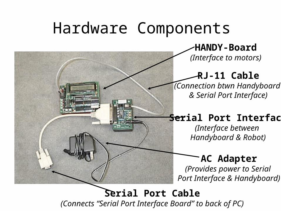
Hardware ComponentsHANDY-Board(Interface to motors)
Serial Port Interface(Interface between
Handyboard & Robot)
AC Adapter(Provides power to Serial
Port Interface & Handyboard)
Serial Port Cable(Connects “Serial Port Interface Board” to back of PC)
RJ-11 Cable(Connection btwn Handyboard
& Serial Port Interface)

HANDY-Board Layout
Ports 0,1,2,3 for MOTORs(Connect a wire from
Port 0 to your LEFT motorAnd another wire
from Port 2 to your RIGHT motor)
LCD Screen (for output from your ROBOT)
ON/OFF Button
Download Connector(Connect Serial Port Interface Board
to Handy-board here)
I LOVE ECE001!

Building a Robot Chassis
• Using the Legos provided, construct a small chassis capable of carrying the load of the handy-board.
• Attach motors to chassis.• Attach a gear to the motor, as shown on the following
page (figure 1).• Put a gear and wheel combination on an axle.• Align two gears as shown in figure 2.

Figure 1
Attaching Gear/Axle to Chassis
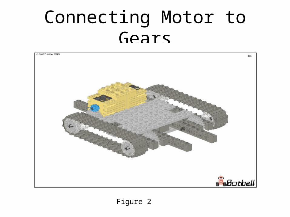
Connecting Motor to Gears
Figure 2

Wire Connections From Motors to Handy-Board
Figure 3

Review of Motor Control and IC Programming

Procedure to Attach and Test Motors on Robot
1. Attach the two motors to the connector wires. Next, attach the wire plugs to Handyboard ports.
2. Turn the Handyboard on.
3. Open your Interactive C software. Make sure the computer is talking to the controller.
4. In interactive window, type “fd(1);”
5. After making sure motor connected correctly, type “off(1);”
6. Turn on motor 1 using the motor(n,x) command.
7. Make motor 1 alternate between a forward and backward direction.
8. You can change the speed of your motors. For example motor(1,100) means motor 1 is turning at 100 or full speed.

Sample Motor program
void main() {
printf("Press START to test motors\n"); while(!start_button()); // wait for start button press
fd(1); // motor in port 1 go forward sleep(2.0); // sleep for 2 seconds
bk(1); // motor in port 1 go backward sleep(2.0);
off(1); // turn motor in port 1 off fd(3); // motor in port 3 go forward sleep(2.0);
bk(3); // motor in port 3 go backward sleep(2.0);
off(3);}
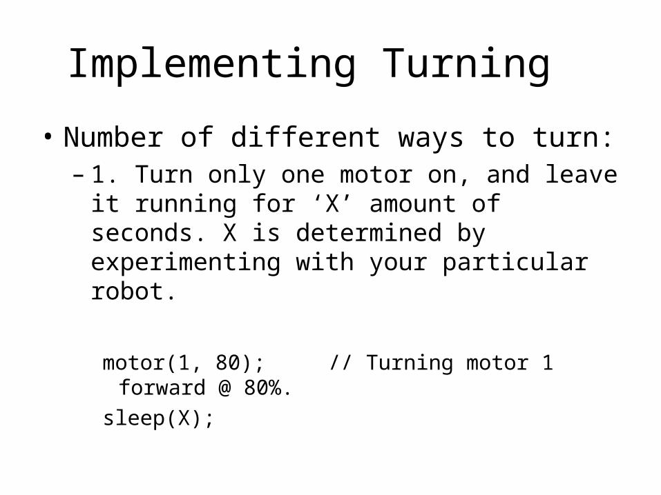
Implementing Turning
• Number of different ways to turn:– 1. Turn only one motor on, and leave it
running for ‘X’ amount of seconds. X is determined by experimenting with your particular robot.
motor(1, 80); // Turning motor 1 forward @ 80%.
sleep(X);

Turning continued…
– 2. One motor forward, opposite motor backwards, and then leave for X seconds.
motor(1, 80); // Motor 1 goes forward @ 80%.motor(3, -80); // Motor 3 goes backward @ 80%.sleep(X); // X determined experimentally by
// programmers/designers.
Although not as efficient, you can also turn by having both motors going in the same direction, but at different speeds.

Calculating the time, X
• Write a short program to make a robot turn, using one of the mentioned techniques.
• Put X = 2.0, and run the program.• See how much the robot turns. Change the
value of X accordingly. If turn is much greater then 90 degrees, lessen the time, X. If it is smaller, put a larger time.
• Keep repeating until your robot executes a near perfect 90 degree turn.

2 Different Types of Loops – You may need them while programming• To repeat a group of commands until a
condition is no longer true, we use a WHILE loop
• To repeat a group of commands a predefined # of times, we use a FOR loop
Examples:
while (stop_button()==0){
beep();}
for (int count=0; count<=4; count++){
beep() ;}
WHILE LOOP FOR LOOP
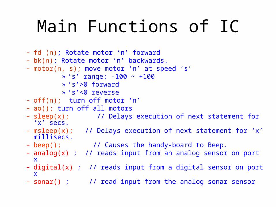
Main Functions of IC– fd (n); Rotate motor ‘n’ forward– bk(n); Rotate motor ‘n’ backwards.– motor(n, s); move motor ‘n’ at speed ‘s’
» ‘s’ range: -100 ~ +100» ‘s’>0 forward» ‘s’<0 reverse
– off(n); turn off motor ‘n’– ao(); turn off all motors– sleep(x); // Delays execution of next statement for ‘x’ secs.– msleep(x); // Delays execution of next statement for ‘x’ millisecs.– beep(); // Causes the handy-board to Beep.– analog(x) ; // reads input from an analog sensor on port x– digital(x) ; // reads input from a digital sensor on port x– sonar() ; // read input from the analog sonar sensor

Project 1 Overview

Maze Specs
Start point
1.5’
1.5’
4’
4’
End Point
1.5’
1.5’1.5’
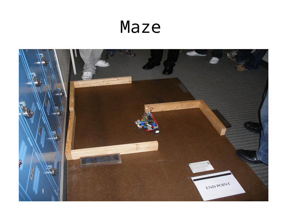
Maze
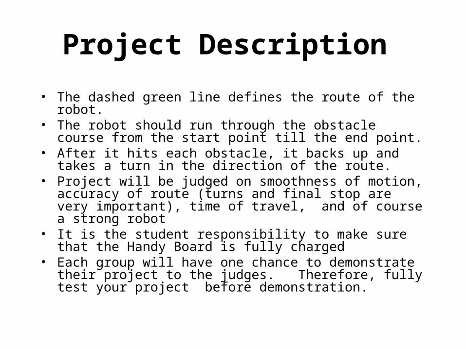
Project Description
• The dashed green line defines the route of the robot.• The robot should run through the obstacle course from
the start point till the end point. • After it hits each obstacle, it backs up and takes a turn
in the direction of the route. • Project will be judged on smoothness of motion,
accuracy of route (turns and final stop are very important), time of travel, and of course a strong robot
• It is the student responsibility to make sure that the Handy Board is fully charged
• Each group will have one chance to demonstrate their project to the judges. Therefore, fully test your project before demonstration.

General Flowchart
Start Button?
Go Straight
Sensor hit?
Backup Count < 2?
Turn Left
Backup
Turn Right
Count=0
Yes
Yes
Yes No
No
No

Project Requirement
• Making your robot escape from the maze Successfully (90 Points)
• Optional (10 points for implementing either 1 or 2)1.Using analog sensors, i.e. sonar or optical
range finder, program your robot so that it is able to find its own path out of the maze.
2.Adjusting your robot to make a perfect 90 degree turn with the reference of the black paper strip

Some Sample Robots
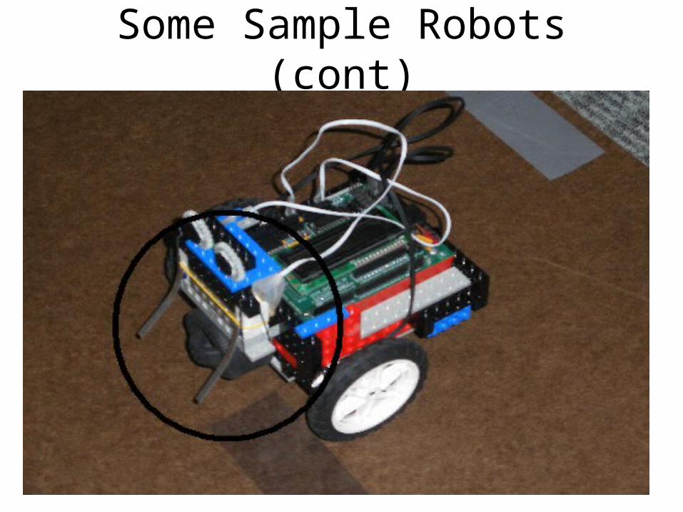
Some Sample Robots (cont)

Some Sample Robots (cont)

Sample code To Use Bumpers
// Program to make a robot go forward.// If hit detected, go backwards for 4 seconds.
void main(){ while(start_button()==0){ }; // Waits for user to
// press start button.while(1){
motor (1,3); // Turn on motor 1, @ 3% of speed.motor (3,3); // Turn on motor 3, @ 3% of speed.
if (digital(13)= =1) // Check sensor connected to port{
motor (1, -3); // Turn on motor 1, @ 3% of speed in opposite direction. motor (3, -3); // Turn on motor 1, @ 3% of speed in opposite
direction. sleep(4.0); off(4); sleep (5.0); } }

Today’s Lab Task
• Check your components in the small box with “parts list check out” on the course website
• Design your robot and finish building it with legos• Write up IC codes to implement one turn• Test your one-turn codes with the robot• HW: Every student has to write a program for this project
individually!
• Extra: Finish coding• Extra: Discuss the bonus part of the project with your
group members

Next Lab – Project Practice
• Select one program from your member’s to be the final project program
• Debug it and test your robot
• Think about the bonus part and try your best to finish the project with bonuses