the geomechanics workshop - armaarmarocks.org/documents/geomechanics_workshop_report_08-24-1… ·...
TRANSCRIPT
ARMA 2010 Workshop Report
10/12/2010 Page 1 of 30
The ARMA Geomechanics Workshop
Saturday, June 26, 2010 Treasure Mountain Inn
Park City, Utah
In conjunction with the
44th U.S. Rock Mechanics Symposium
and the
5th US/Canada Rock Mechanics Symposium
Report prepared by:
Dr. Priscilla P. Nelson New Jersey Institute of Technology
ARMA Life Member and Fellow

ARMA 2010 Workshop Report
10/12/2010 Page 2 of 30
The Geomechanics Workshop
Saturday, June 26, 2010 Treasure Mountain Inn
Park City, Utah
44th U.S. Rock Mechanics Symposium 5th US/Canada Rock Mechanics Symposium
Agenda
Morning The morning session focused on panelists‟ perspectives concerning what has been important for rock mechanics and engineering to achieve in the past 50 years, and to identify what we did and did not achieve (i.e., what has been hard to achieve, what we still have to accomplish). Each panelist identified greatest breakthrough/ development/achievements of the period. This was a real opportunity for the audience to learn from some of the most prominent rock mechanics educators and practitioners in North America.
Meet the panel
Presentations of personal perspectives on what we have accomplished over the past 50 years
Discussion, Q&A Lunch Afternoon The afternoon session focused on the future. Panelists were invited to frame what they see
as the issues of the future (the scope for this future vision should be taken as on the order of 10 years) that require and warrant attention and resolution (if not solution) by the rock mechanics and engineering community. Issues included new roles for rock mechanics and engineering in the economy of the future, demands/needs for new methodologies and technologies, likely opportunities to accomplish something we have not been able to accomplish to date, and concerns regarding the profession of rock mechanics and
engineering, including educational aspects and leadership succession. What should/must the rock mechanics and engineering community be doing now to be successful regarding the issues of the future (e.g., we don‟t want to be having the same conversation 10 years from now)?
Personal perspectives on what we can/should/must achieve in the future (10 year horizon)
Discussion, Q&A Evening Sponsored reception at the Park City Museum

ARMA 2010 Workshop Report
10/12/2010 Page 3 of 30
Panelists
Don C. Banks
Don Banks has been an incredibly active and important contributor to the Fields of Rock Mechanics and Engineering, keeping an eye on Civil and Military applications from his position as Chief, Soil and Rock Mechanics Division at the U.S. Army Corps of Engineers Waterways Experiment Station (WES) in Vicksburg, MS.
From the earliest days, computerization found eager support in Don‟s Division. Through the 1960s and into the 1980s, the Corps led in promoting the Finite Element Method (FEM) and in hosting major conferences, seminars and educational workshops. Complementing FEM programs, WES engineers helped develop and apply other finite-element-analysis-based computer programs to specific rock mechanics problems, including displacements along joints and other discontinuities. Notably, Peter Cundall of the University of Minnesota was instrumental in formulating an applicable Distinct Element Method (DEM), and Don supported both code development of DEM as well as pursuing field applications.
Perhaps the most promising rock mechanics numerical model to evolve through the 1980s and into the 1990s was Discontinuous Deformation Analysis (DDA). Gen-Hua Shi, upon arriving in the United States from China about 1980, began collaborating at U.C. Berkeley, and by 1984 Shi had become the primary developer and proponent of DDA. Anticipating the importance of DDA to rock mechanics problems, Don Banks hired Shi as a full-time researcher through 1997. Under Don‟s leadership, WES was an incredibly important source of intellectual support and funding for rock mechanics computational research in the US.
Following his retirement from WES in 1997, Don has continued to consult with major water resource and other Federal agencies on geotechnical projects.
William G. Pariseau
Bill Pariseau is a professor and holder of the Malcolm N. McKinnon Endowed Chair in Mining Engineering at the University of Utah. He received his B.S. in Mining Engineering from the University of Washington, and his PhD in Mining Engineering and Rock Mechanics from the University of Minnesota. He started his teaching career at Penn State and Montana Tech, subsequently joined the mining engineering faculty at the University of Utah, and has been a prolific contributor ever since. He retired to Emeritus Professor status as of June 2010.
Bill‟s research has focused on fundamental and applied rock mechanics, especially stability of surface and underground excavations for mining purposes. He is generally interested in broad and exciting science and engineering issues in rock mechanics. Natural rock masses pose many interesting questions not present in the mechanics of manufactured materials. Numerous structural and material discontinuities in rock ranging over mm to kilometer scales are the source of many key issues in rock mechanics. His research career has been aimed at developing greater realism in rock engineering through a rational approach to the central question of "What to do about the joints?”. His approach is to integrate laboratory testing, finite element modeling of uncoupled and couples

ARMA 2010 Workshop Report
10/12/2010 Page 4 of 30
processes, and mine measurements to test various hypotheses about equivalent properties applications to jointed rock mass behavior with the aid of graduate students.
Maurice B. Dusseault After flunking out of University in 1965, Maurice started in the oil industry as a roughneck for a year, then as a drilling fluids specialist for two years. On orders from his future wife, he returned to university and obtained a PhD in Civil Engineering from the University of Alberta. In 1977, he was awarded a five-year research chair at the University of Alberta funded by the Alberta Oil Sands Technology and Research Authority. Since 1982, Maurice has been a Professor of Geological Engineering in the Earth and Environmental Sciences Department, University of Waterloo, Waterloo, Ontario, Canada.
He carries out research in petroleum geomechanics (drilling, hydraulic fracturing, reservoir geomechanics), new heavy oil production methods, salt mechanics (mining, storage), and deep waste disposal. He has co-authored two textbooks and over 450 articles in conferences and journals, and works with industry as an advisor and instructor. Maurice has developed a number of short courses in Petroleum Geomechanics and related areas, and gives these courses to companies, government agencies and professional groups in countries around the world. For example, his course on New Oil Production Methods, with a focus on heavy oil production and geomechanics, has been given over 25 times in 13 countries. Fortunately, his loud voice and robust constitution sustain him during these one-week professional courses.
Professionally, Maurice is a member of SPE, ISRM, EAGE, CHOA and several other more obscure groups of letters. He was asked to be a SPE Distinguished Lecturer in the year 2002-2003, so he visited 19 different countries speaking about new oil production technologies to 28 separate SPE Sections. He did have enough sense to say no to going to China during the SARS outbreak at that time, but did end up in some remote places such as Atyrau and Aktau in Kazakhstan, and Ahmadabad in India.
In 2010, Maurice was asked to form a new International Society for Rock Mechanics (ISRM) Commission on Petroleum Geomechanics to foster and promote this subject within the ISRM mandate. This Commission is slowly being organized around a number of experienced persons with various petroleum geomechanics expertise, and in years to come, Maurice hopes that this area of rock mechanics becomes as important to the ISRM as mining and civil rock mechanics. John H. Curran John Curran is the founder and director of Rocscience, Inc., and Professor Emeritus and former holder of the Robert M. Smith Chair in Geotechnical Mine Design and Analysis at the University of Toronto, Canada. His research spans rock mechanics, geotechnical design and computational geomechanics, including development of boundary element and finite element techniques for 2D and 3D stress analysis used in mine design and geotechnical applications. His research led him to establish Rocscience in the 1980‟s with a vision to incorporate leading-edge geomechanics research findings into easy-to-use software tools for the geotechnical and mining

ARMA 2010 Workshop Report
10/12/2010 Page 5 of 30
industries. John saw the growing interest of mining and civil engineering companies for user-friendly, reliable design and analysis software tools. At the time, these industries were facing safety concerns and increasing development costs. They needed analytical design tools that would enable engineers to safely and economically design tunnels and other forms of underground excavations. His company continues to develop software that is used extensively by practitioners in the fields of civil and mining engineering in over 80 countries around the world. Richard E. Goodman Dick Goodman began his academic career at the age of 15 years at Wisconsin, but this phase ended abruptly with the arrival of his mother, who, after seeing his fraternal surroundings, decided to dis-enroll her son at the end of the academic year. He relocated to Cornell University and received a BA in Geology and an MS degree in Civil Engineering and Economic Geology from Cornell University. He received his PhD in Geological Engineering from the University of California at Berkeley in 1963, and served as a Professor of Geological Engineering at UC Berkeley until his retirement to Emeritus status. His research in applied rock mechanics led to development of the joint element for finite element analysis (with Robert Taylor), introduction of the base friction model test, and the development of block theory (with Gen Hua Shi). He is the author of five books, including Karl Terzaghi, the Engineer as Artist. He was also a classical pianist and an opera singer (baritone) who had studied voice at the Royal College of Music in London and in San Francisco. Tired of commuting to sing operatic roles, he founded Berkeley Opera in 1979 so he could sing closer to home. In 30 years, the company has grown to become what one critic called "one of the more interesting small companies in the nation" with unique and high quality presentations. While he is playing more classical piano than singing opera these days, he still does operas and concerts as a singer (and producer and stage director) with a little company in Mendocino – the Mendocino Chamber Opera – with one production per year at the Art Center in his wonderful small town. Charles H. Dowding Chuck is Fellow and former member of the board of directors of the American Rock Mechanics Association, and a former chairman of the ASCE Rock Mechanics Committee. In 2000, he chaired the committee that wrote the ARMA/NSF report “Rock Engineering Issues in Underground Urban Infrastructure Construction.” He is currently a consultant for the Metro North Railroad for oversight of blasting to extend the Long Island Railroad into Grand Central Station in New York City. He was a six year member of the board of directors of the International Society of Explosive Engineers and founded Digital Vibration Inc., the first company to perfect remote digital blast vibration monitoring in the early 1980‟s. He received his BS from the University of Colorado and PhD from the University of Illinois, was a Royal Norwegian Fellow at the Norwegian Geotechnical Institute, and taught at MIT before joining Northwestern University, where he is a professor of Civil and Environmental Engineering. In rock mechanics and geotechnical engineering Chuck is best known for his four books: Construction Vibrations, Blast Vibration Monitoring and

ARMA 2010 Workshop Report
10/12/2010 Page 6 of 30
Control, GeoMeasurements by Pulsing TDR Cables and Probes, and Micro-Meter Crack Response to Vibration and Weather. Along with coauthors, he received the Applied Research Award from the U. S. National Committee on Rock Mechanics for work on blast induced cracking of structures. Currently he is developing systems to autonomously monitor and display the status of critical facilities through the Infrastructure Technology Institute at Northwestern University. In 2005, his research group won third place in Crossbow Technology's "Smart Dust Challenge" for the development of a “Wireless Data Acquisition System for Autonomous Crack Measurement Projects.
Moderator
Priscilla P. Nelson
Currently Professor of Civil and Environmental Engineering, Priscilla
joined the New Jersey Institute of Technology in 2005 as Provost and
Senior Vice-President for Academic Affairs. Prior to that, Professor
Nelson had spent 11 years at the US National Science Foundation (NSF)
including service as Senior Advisor to the Director. She was a Professor
in Civil Engineering at the University of Texas at Austin from 1983 to
1996.
She became an engineer through the “back door” – starting with a BS degree in geological sciences from the University of Rochester (1970) and masters degree in geology (Indiana University, 1976). After a stint working on the Trans-Alaska pipeline, she finally took some engineering courses, earning an MS in structural engineering (University of Oklahoma, 1979) and, in 1983, she received her PhD degree in geotechnical engineering from Cornell University.
Priscilla has an international reputation in geological and rock
engineering, and the particular application of underground construction. She also has worked in the areas
of critical infrastructure, emergency response and disaster recovery. She has published more than 120
technical and scientific publications in refereed journals and conference proceedings. She is a
Distinguished Member of the American Society of Civil Engineers (ASCE), former president of the Geo-
Institute of ASCE, a lifetime member and first president and Fellow of the American Rock Mechanics
Association, and a Fellow of the American Association for the Advancement of Science (AAAS). She was
elected Chair of the Division of Engineering of AAAS in 2007. In addition to these positions, she has
many other professional affiliations including: Sigma Xi, Tau Beta Pi, the American Underground-
Construction Association, the Association of Engineering Geologists, the International Tunneling
Association, the Society of Women Engineers, the Association of Women Geoscientists, and the
American Society for Engineering Education (ASEE).
Dr. Nelson has received many honors and awards, including Exxon Teaching Fellowship at The
University of Texas at Austin (1985-1987), the Case Studies Award and the Basic Research Award from
the US National Committee for Rock Mechanics (NAE), election to The Moles - an association of the
heavy construction industry (1995), and induction into Tau Beta Pi as an Eminent Engineer (2007). In
2008 she received the Kenneth Andrew Roe Award from the American Association of Engineering
Societies (AAES), and she is currently a member of the Advisory Group to the Center for Engineering,
Ethics, and Society of the US National Academy of Engineering (2008- 2011). Dr. Nelson has been a
part of several major construction projects, served as a consultant to the U.S. Department of Energy and
the State of Texas for the Superconducting Super Collider project, and she received Presidential
appointments to the U. S. Nuclear Waste Technical Review Board in 1997 and 2001.
ARMA 2010 Workshop Report
10/12/2010 Page 7 of 30
The Workshop Report
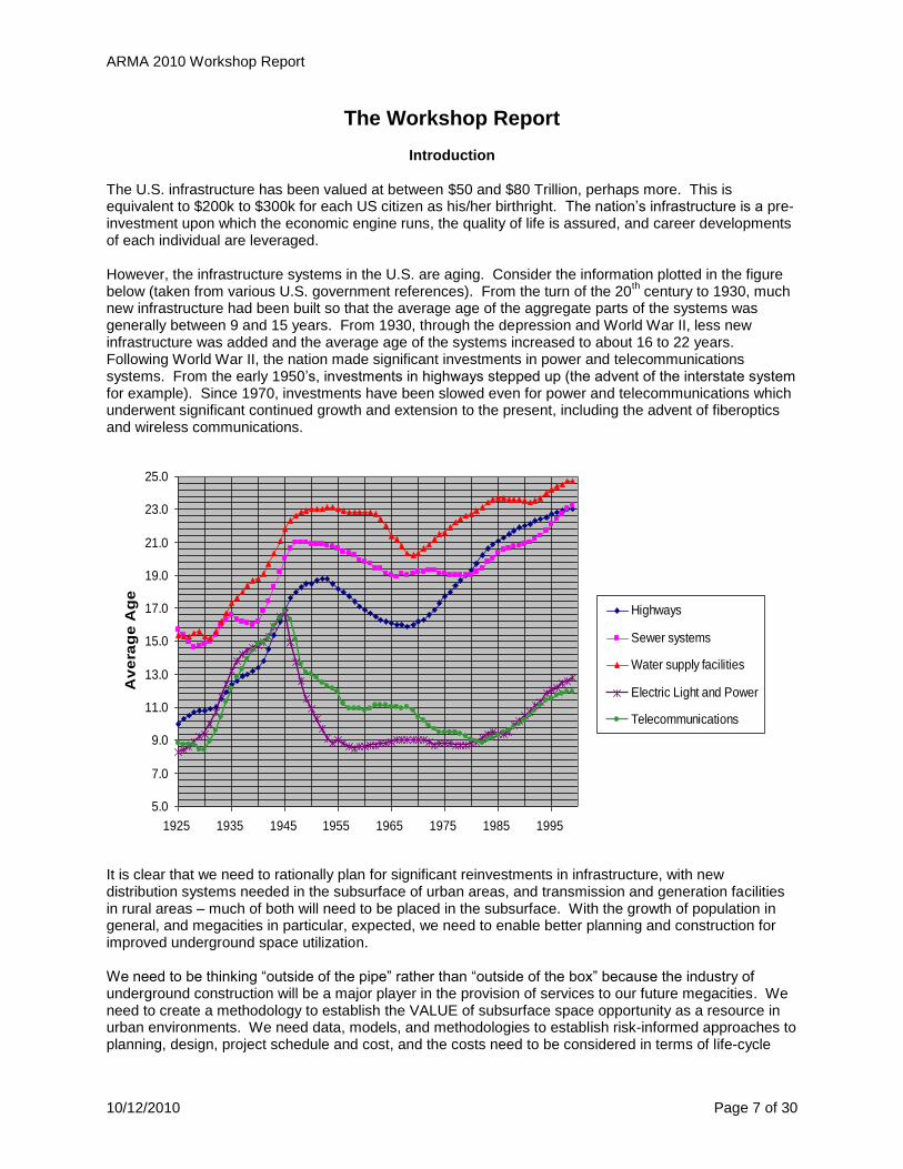
Introduction The U.S. infrastructure has been valued at between $50 and $80 Trillion, perhaps more. This is equivalent to $200k to $300k for each US citizen as his/her birthright. The nation‟s infrastructure is a pre-investment upon which the economic engine runs, the quality of life is assured, and career developments of each individual are leveraged. However, the infrastructure systems in the U.S. are aging. Consider the information plotted in the figure below (taken from various U.S. government references). From the turn of the 20
th century to 1930, much
new infrastructure had been built so that the average age of the aggregate parts of the systems was generally between 9 and 15 years. From 1930, through the depression and World War II, less new infrastructure was added and the average age of the systems increased to about 16 to 22 years. Following World War II, the nation made significant investments in power and telecommunications systems. From the early 1950‟s, investments in highways stepped up (the advent of the interstate system for example). Since 1970, investments have been slowed even for power and telecommunications which underwent significant continued growth and extension to the present, including the advent of fiberoptics and wireless communications.
It is clear that we need to rationally plan for significant reinvestments in infrastructure, with new distribution systems needed in the subsurface of urban areas, and transmission and generation facilities in rural areas – much of both will need to be placed in the subsurface. With the growth of population in general, and megacities in particular, expected, we need to enable better planning and construction for improved underground space utilization. We need to be thinking “outside of the pipe” rather than “outside of the box” because the industry of underground construction will be a major player in the provision of services to our future megacities. We need to create a methodology to establish the VALUE of subsurface space opportunity as a resource in urban environments. We need data, models, and methodologies to establish risk-informed approaches to planning, design, project schedule and cost, and the costs need to be considered in terms of life-cycle
5.0
7.0
9.0
11.0
13.0
15.0
17.0
19.0
21.0
23.0
25.0
1925 1935 1945 1955 1965 1975 1985 1995
Av
era
ge
Ag
e
Highways
Sewer systems
Water supply facilities
Electric Light and Power
Telecommunications

ARMA 2010 Workshop Report
10/12/2010 Page 8 of 30
costs including direct costs for construction, sustainable operation and maintenance, long-term usage and performance, flexibility in re-use and rehabilitation leading to cradle to grave costs, and also to include those difficult to quantify indirect and social costs that are very important to system sustainability and resilience regarding extreme events (e.g., climate change, hurricanes, earthquakes, terrorism). Therefore, the infrastructure reinvestment drivers include:
Megacity and demographic growth demands: o Rehabilitation/repurposing of existing critical infrastructure systems. o Extensions of existing systems. o New systems in the developing world. o Systems that serve an aging population.
Equity, infrastructure service as a human right, and multicultural and societal issues are growing in importance globally.
The need to respond to the threats from global climate change and concern for sustainability of the natural, human (social) and built environments, and the attendant increasing frequency of disaster occurrences.
Infrastructure costs that monotonically increase at the same time as the fragility of national and global economies is not well understood.
Resource crises that expand in criticality, with foci on water and energy. Rock mechanics and engineering advances have enabled much of what has already been accomplished to serve the U.S. infrastructure needs, and additional advances will be required to enable a robust future with the nation prepared for the challenges it will face. In particular, we need to take advantages and opportunities for underground development in the urban environment by research in the following areas:
• Minimize consumption of nonrenewable energy resources, maximize sustainability.
• Construction methods and materials, direct and indirect first costs. • Urban planning – integrate surface and subsurface space resources. • Negative impacts. • Resiliency. • Smart facilities. • Lifecycle, M&O costs. • Infrastructure systems integration.
We also need to engage in policy issues, and work toward an enhanced public and technical community understanding of the role of rock mechanics and engineering in the sustainability of the nation‟s infrastructure service provision.

ARMA 2010 Workshop Report
10/12/2010 Page 9 of 30
Morning Session – Past Achievements
Comments from Don Banks Researchers in the U.S. have been major contributors and leaders in many areas of rock mechanics and engineering in the past 50 years:
The US has led in computational modeling and code development for the world. – The Waterways Experiment Station (WES) of the U.S Army Corps of Engineers, led by
Don Banks was very important for the evolution of modeling capabilities, and responding to the need for complex and accessible data resources for validation of both computation and empirical (e.g., rock mass classification based) models.
– In a similar context, the Deep Underground Science and Engineering Laboratory (DUSEL, in planning through funding by NSF and DOE) will provide a contextual and deep platform for continued work on experimentation and model validation.
We have a continued need for knowledge about rock mass properties – especially validated models:
– for repair and rehabilitation of underground structures and facilities (the Corps isn‟t really building anymore), and
– for underground facility detection.
We need a new and compelling national program that will drive continued research contributions and advancement of military/civil applications – else we won‟t be able to gain sustained funding through the political process.
– In the 1960‟s, peacetime use and nuclear weapons (DoD) were main drivers for research investments, e.g., $5M was spent in site investigation at Buckboard Mesa on the Nevada Test Site – what did we learn and where is the information?
– Old data bases developed for DoD and other projects are still around and being mined for new understandings, but some/much of the information is now lost and/or of uncertain applicability. And we haven‟t really used available information resources as we might have – consider how the research community in aggregate has used (or not used) the Yucca Mountain project.
– The DUSEL project may serve as a needed focus for advancement in deep rock mechanics. This project is pertinent – more applications are going deep so that stresses and thermal regimes are increasing in importance. To a certain extent, we may be able to exploit a convergence of dual use interests - civilian and DoD.
– We need to consider new systems with creative thinking about “dual use” in underground space, including the use of underground space itself as a resource – not just for what we remove (e.g. ore, aggregate), but for the space itself.
We still do not have a mature understanding of rock properties, in particular rock mass properties. – In the 1960‟s we were pretty naïve – Deere‟s RQD is overly simple but 50 years later we
are still using it. – In the 1960‟s, the finite element method (FEM) had immediate application to rock
mechanics – e.g., early WES-supported work at Berkeley. – In the 1960‟s, the Omaha District office of the Corps was working for the Cheyenne
Mountain project but turned this involvement over to Don Banks at WES. Don started supporting Peter Cundall at Minnesota first to build a computer and then to develop the distinct element method (DEM).
– In the 1980‟s, Don and WES supported development of block theory, Discontinuous deformation analysis (DDA, Shi and Goodman, and WES hired Gen Hua Shi for a while during the development (under the Air Force ballistic missile contract).

ARMA 2010 Workshop Report
10/12/2010 Page 10 of 30
– We also gained rock mass property data from the Waste Isolation Pilot Plant (WIPP) project in New Mexico during the 1980‟s and 1990‟s.
We should be aggregating our data, building data resources and providing curation, easy access to validate rock mass classifications and their inferences, and to validate computer simulations
– Maybe we should develop a simulated “generic mountain” that can be used in a testbed mode for cross-code or method comparison.
We still have work to do on hydrologic modeling. – WES worked at the Rocky Mountain Arsenal – they spent a lot of time and money
building a model but never were able to validate it.
We are not using geophysical methods to our best advantage – – In general, the methods and technology is oversold but underused, particularly in
application for civil and mining engineering – The equipment for geophysical applications gets better, but we are still using old
techniques – We need to look for integration of methods, synergy and complementarity.
We have worked for decades on the detection of underground openings, but cannot yet count ourselves successful.
– Under dams – Tunnels (e.g., DMZ, US/Mexican border) – Unexploded ordinance
We need to consider new systems with creative thinking about “dual use” in underground space, including the use of underground space itself as a resource – not just for what we remove (e.g. ore, aggregate), but for the space itself.
– Especially in urban planning with population growth as a driver, underground space must be considered a public resource that should be valued just as are surface acreage, air rights, and subsurface water and mineral rights.
– Regarding deep underground space, there‟s a LOT happening in deep space outside of the U.S. for defense purposes - and we need to look at transferring mining approaches to rock mass understanding into civil/security domains and deep applications.
– The developing world will have huge needs for underground space in rock, and the U.S. used to educate the world in this area…is this at all true any more?
Morning Session Comments from Bill Pariseau “Mine Engineering Rock Mechanics…a personal view”
Bill Pariseau identified seven areas of major achievements in the past, incorporating advances in laboratory testing, mine measurements, analysis, comparisons, demonstration, etc.: 1. Mine Fill
There has been a great deal of research on fill leading to recognition of mine fill as an engineering material, especially by the Spokane research lab (USBM), for application to narrow-vein mining. Example – consider the accompanying Powerpoint slide (separate posting on the ARMA web site) of two stopes below that were from a Spokane Research Laboratory (SRL) project that involved lab testing, mine measurements, and numerical modeling all put together. Fill was hydraulically placed as an innovation at this site in two mines in the Coeur d‟Alene Mining District. The data indicates the fill pressure built up during mining, and the effectiveness of the fill in reducing displacements is clear during mining. A work stoppage also occurred – but pressure was maintained and there was little

ARMA 2010 Workshop Report
10/12/2010 Page 11 of 30
time-dependency and closure in that interval because of the fill. Mine observations and numerical modeling led to fill guidelines being established.
2. In Situ Stress Measurement
Stress measurements have come a long way. Doorstoppers were the first early equipment that saw use in mines. A major breakthrough was the USBM borehole deformation gauge – for determination of the 3-D stress state, three cell readings are required in three holes. The most-used stress measurement instrumentation now is the CSIRO – hollow cell stress gauge – this allows measurement of 3-D stresses by one gauge in one hole.
3. Stress Analysis for Design
In early days – stress analysis was theoretical and analytical based on elasticity, using simple geometry solutions. Early publications for advancement of rational mine design include:
• La Mecanique des Roches, J. Talobre, 1957 • Rock Mechanics and the Design of Structures in Rock, L. Obert and W. I. Duvall (1967). • Elasticity, Fracture and Flow, J. C. Jaeger, 1969 • Rock Mechanics Principles, D.F. Coates,1970.
All were useful. There was a bit of 3D analysis for spheres and spheroids in 1940‟s by Terzaghi and Richart. True triaxial ellipsoids were considered in 1940‟s by Sternberg and Edwards. Mainly, what was available were analytical solutions for stress concentrations about holes of simple shape, using results from elasticity theory for simple shapes such as circular and elliptical holes. Other shapes using complex variable theory were also studied during this pre-computer era.
4. Rock Slope Stability
Open cut engineering is an issue of great economic importance that is subject to some engineering control. The subject was greatly advanced by the breakthrough work of Evert Hoek‟s wonderful group at Imperial College (UK) (Hoek and Bray, 1974, Rock Slope Engineering) which considered wedge failures, joints, toppling, slip circles (weak soils), the importance of drainage, and blasting. Today – the state of the art is advanced considerably, driven by open cut mine economics. We are still dealing with wedge failures, joints, toppling, slip circles, drainage, blasting – but now with risk analysis and now in color! (e.g., Guidelines for Open Pit Slope Design, J. Read and P. Stacey (eds) 2009).
Field instrumentation has also become advanced, e.g., wireline extensometers, etc. These can be read in the office – a danger that one now has fewer reasons for getting his/her boots dirty!
5. Cable Bolting and Vertical Crater Retreat (VCR) Mining
VCR mining reduced development costs by 30 to 35% and therefore became competitive with other methods where conditions were right. The figures on VCR mining in the Powerpoint slides are from the Homestake Mine in SD. Short mast drills and cable bolts were developed for application of this new method. At Homestake, Bill was part of a research team doing a cable bolt project as well, with much instrumentation including extensometers and cable bolts. The cable bolts were instrumented with strain gauges to get simultaneous measurement of force and displacements. VCR measurements and FEM modeling produced excellent correlation (R=0.84) between predicted and observed forces and displacements. Similar results at the Carr Fork Mine led to a Case History award by the U.S. National Committee for Rock Mechanics.
6. Drift and Fillcrete Mining
In Nevada, drift and fillcrete mining is used. In this method, a drift is mined out (and perhaps another) and then these are filled with fillcrete. This fill is a crushed aggregate with a slurry cement. Fillcrete

ARMA 2010 Workshop Report
10/12/2010 Page 12 of 30
can ultimately support spans of 75 ft or more, permitting safe and unsupported mining under the filled drifts. Experience indicates that even with a cold joint in the fillcrete roof after a blast – the roof and opening are in good shape.
7. Numerical Methods for Design
Slope stability is a very important problem for surface mining and numerical analysis. Cost impacts of slopes are huge – estimated $15 to $20 million per degree for slopes deeper than, 1 km depth. Bill sett up a instrumentation system for monitoring the slopes in the north wall of the Berkeley pit. The system used manually-read wire extensometers to record over 16 ft of displacement over several years. The slopes never failed catastrophically. Whether a slope fails fast or slow is a big question for surface mine engineering. The Berkeley resource in Butte has had 7 episodes of mineralization, and it is in Butte that mining research really got underway. At the Berkeley mine, there was something in the area for everybody. In underground mining, numerical analyses are used widely. Bill remembers in early days when he needed to analyze a mesh of 250 2D elements at Montana State – something only possible after midnight when the whole campus computer system could be devoted to the problem. Now he can analyze over 250,000 3D elements on his PC and get a fast solution. There are many types of codes are available – all require physical laws (kinematics, material laws); equilibrium (static, dynamic) equations; strain displacement equations; stress strain equations
• Continuum codes: FEM, BEM, FD (finite difference) • Rock Block codes: DEM, NMM (Numerical Manifold Methods), DDA
NOTE: Continuum codes accommodate discontinuities and Rock Block codes accommodate deformable blocks.
Morning Session Comments From Maurice Dussealt “Petroleum Geomechanics”
Initial comments
Estimation of stresses and pressures before and during drilling is of paramount importance Problems common with borehole stability, lost circulation through hydraulic fracture (p > σhmin)
During drilling about 50% of the blowouts occur because of increasing problems with borehole stability that made well control more challenging.
Cement strength (frictional, cohesive) Geomechanics is involved in all aspects of the petroleum industry… Petroleum engineers MUST BE BETTER TRAINED IN GEOMECHANICS
Petroleum Geomechanics Commission SPE has been more active in Petroleum Geomechanics than has ISRM (which has largely
ignored the field) ARMA conferences have made important contributions to Petroleum Geomechanics 2010 – ISRM has formed the Petroleum Geomechanics Commission To promote this area within the ISRM and in the World
Also, this Commission intends to extend beyond Petroleum Geomechanics to e.g., geothermal, hydraulic fracturing, waste disposal, THMC (thermo-hydro-mechanical-chemical) coupling, borehole stability, HPHT (high pressure, high temperature) field development Where are we in Petroleum Geomechanics?
We understand some issues quite well…
Earth stresses and pressures
Reservoir compaction, surface subsidence
Stress transfer (Mandel/Kryer or Nordbeergum effect)
Flow-stress coupling (σ‛-p-ΔV)

ARMA 2010 Workshop Report
10/12/2010 Page 13 of 30
Hydraulic fracturing (elastic, non-thermal)
Borehole stability in drilling
Initiation of sand production (not flux) – when you allow some sand, you can increase production by 40 to 50%
Several other issues Earth Stresses and Pressures - World Stress Map Project
Driven by need for deep disposal (permanent and extremely safe) waste disposal Academically based effort Compendium of data from around the world Data is very dense in some regions, but… There are large regions where coverage could be much denser if oil companies released more
data More Gulf of Mexico data would be useful for engineering, safety, and risk management (Gulf
Formation Pressure Database – including pressures at depths of 4 to 5 miles that are 95 to 98% of the overburden stress – rock is “floating” – lots of mechanics effects can happen).
Compaction and Subsidence – Ekofisk case (similar to diatomite in California)
High porosity Chalk – 2 to 3 km deep with 50% porosity – when we draw down the pore pressures, the effective stresses go way up
Hollow coccoliths, little cement Unanticipated massive compaction – 8 m compaction at the sea floor
Seafloor subsidence
Leads to wave risks for platforms
Casing shearing (every well has been redrilled several times)
Wonderful drive sustaining process - Stress-Pressure Coupling! p – σ' coupling improves well test analysis, even in linear elastic systems
Massive subsidence – huge subsidence bowl, 10 km in diameter, wells experience compaction failure in center, shear failure in flanks
Trigger for coupled stress analyses in Petroleum Geomechanics
Effects on pressures - a coupled model shows clearly the “Nordbeergum” effect arising from ΔV-Δp-Δσ‟ stress transfer
Already produced 40% over what had been expected A very humbling experience – practical learning consequences:
All well test equations are in error Flow rate predictions wrong by up to 50% This has impact on decision-making One axisymmetric elastic closed-form solution has been developed for this…
Arching effect changes with time Compaction can be delayed until the Δp zone is large enough for σv re-
imposition Early time behavior will under-predict compaction/subsidence
Full mathematical simulation may be needed in critical cases such as: Hydraulic Fracturing (HF)
U.S. peaked in oil production in 1971 and there has been a steady decline since then in rates of production. Same thing for gas production since 1973 except for in the last 4 years when gas has been increasing primarily because of gas shale production with tremendous massive amounts of hydraulic fracturing.
Horizontal versus vertical fracture simulation – mostly horizontal wells – as many as 45 hydraulic
fractures in one well, using multistage packing.
ARMA 2010 Workshop Report
10/12/2010 Page 14 of 30
Shale gas development by hydraulic fracturing (with microseismic monitoring by geophones) – very valuable to give an idea of the volume of the stimulated zone. The interaction of joints with the hydraulic fractures is really interesting. Per Mark Zoback (Stanford), a lot of the permeability increase is happening because of the slip along pre-existing joints. Once they slip and we stop injecting, the joints stay open and continue to produce natural gas.
Barnett Shale (Dallas-Ft. Worth, Texas) and elsewhere – drill so that natural fractures are
perpendicular to the horizontal well, on injection, the network of fractures becomes outlined by microseismic shear events, and the microseismic bursts occur simultaneously along the planes corresponding to the azimuth of the natural fractures. The Marcellus Shale in NY/Pennsylvania and the Horn River shale in British Columbia.
Big Issues remaining
o We cannot mathematically simulate massive hydrofracturing in a naturally jointed rock unit. o HF in cohesionless sandstones (massive plasticity effects on fracture flanks) o HF in naturally fractured strata o Simulation of multiple fractures o Shear displacements across fracture planes (source of the MS activity)
Borehole Stability
A classic coupled problem – thermal, stress, pressure and chemistry – need to combine all four, and we don‟t have good data to model and validate
– Stresses, pressures in the earth o HF if mud weight is too high o Blowout if mud weight is too low
– Geochemistry, mineralogy of shale o Smectitic, Q-I, marly shale, fluid salinity…
– Slip of joints, faults from increased p o High shear stress, weak planes, high MW
– Salt mechanics (not just NaCl, other salts as well, such as carnallite, bischofite…) – Thermal effects (heat bad, cool good for stresses) – Full THMC coupling analyses… various models exist
o PBORE-3D, the Poromechanics Wellbore Stability Simulator (U. Oklahoma) – Stability Analysis with Bedding – Shale
o Shale is susceptible to drilling fluid chemistry – get shrinking and swelling, stress coupled effects. Anisotropic effects. Stable shale in silicate-polyol drilling fluid can be quite different with an other mud
o Borehole Shear Displacement – especially for boreholes in sand. Can develop open hole failures along the wall creating spalled rubble.
– Borehole shear displacement – slip (especially with high mud weights in open holes)) along the strike of the existing joint or fault, may be in reverse or normal sense. May trap the drill strings in the hole
o With new technologies, we can drill backwards out of a hole allowing equipment to avoid being locked up.
– Where to Drill? o Which is the Best Borehole Trajectory Near a Salt Diapir? o Diapir stress regimes are quite remarkable – strong normal faulting conditions
above the diaper, thrust conditions along the shoulders, strike slip along the diaper neck/sides
o Possibilities – through the salt, through the flanks, from a distance around the diaper (probably the best option for access to flank reservoirs).
Sand Exclusion and Control
– Historically – we do not want sand in the well bore

ARMA 2010 Workshop Report
10/12/2010 Page 15 of 30
o Selected and oriented perforations – Use screens and liners to keep sand out (very expensive – could be $3,000 to $4,000 per
meter for screening) o Stand-alone screen o Expandable sand screen o Open or closed hole gravel packing o Cased hole frac pack
– Now more and more have sand coming in and co-production in Heavy Oil o In Venezuela alone, sanding may contribute 30-40 Bb of oil resources o Sanding also increases permeability and compressibility, improves the reservoir o Sanding is a Geomechanics Issue! o Stresses, strength, pressures… o Seepage forces from high-gradient flow, liquefaction from seepage forces o Arching, water hammer effects, and so on…
– A miracle example in Alberta – Luseland field – with sand excluded – 20 to 30 barrels per day production. When sand influx was permitted (open up perforations), oil production rate increased to over 250 barrels per day.
Risk reduction offshore more and more involves geomechanics. 25 years ago – there were very few – now there are hundreds of people involved but there is a continuing need for more people.
Morning Session Comments From John Curran “50 Years of Numerical Modeling in Rock Mechanics”
Historical background
Born as distinct discipline in 1950s o 1st US Rock Mechanics Symposium (1956) at the University of Minnesota o ISRM founded (1962)
Recognition of uniqueness of rock masses (and different from soils) as complex aggregate of o Intact material o Heterogeneous features, particularly joints, faults, shear joints, discontinuities
Application of classical methods of analysis – theories of elasticity and plasticity used in 1960‟s and 1970‟s to estimate what was happening in our rock masses
Tools for Rock Engineering Design
Empirical approaches in 1970‟s and 1980‟s o “Rules of thumb” o Rock mass classification systems (RQD, RMR, Q, etc.) o Stability charts for stand-up time, span versus quality, support needs o Now we have moved on from this – to look into the strength and deformability of the rock
itself so that rational design through computational approaches is possible
Closed-form equations
Generalized methods o Limit-equilibrium methods o Numerical methods
Growth of Rock Numerical Modeling
Factors fuelling growth of numerical modelling (both research and application) o Complexity and uniqueness of rock mass behaviours – departures from classical theories o Increased dimensions of excavations
Benefits of Numerical Modeling
Understanding of excavation / rock mass behaviour and failure mechanisms
Insights into interplay between different input parameters

ARMA 2010 Workshop Report
10/12/2010 Page 16 of 30
Exploration of design trade-offs and alternatives
Interpretation of field measurements and observations
Ultimate goal (Holy Grail) – QUANTITATIVE PREDICTION Numerical Modeling in Rock Engineering
Process of idealizing structure/excavation in rock mass in order to assess behaviour and fitness for intended purposes
o Decisions Geologic domains and materials Geometry Material behaviour and constitutive model Loads, etc.
Components of Numerical Modeling
Choice of numerical methods of analysis
Choice of constitutive relationships
Characterization of rock masses/determination of input parameters (and calibrate)
Comparisons between model results and real world – calibration then validation Numerical Methods
Mathematical methods for solving equations governing deformation of rock masses under loading (excavation, forces, etc.)
o Continuum methods : Finite Element Method (FEM) – tremendous amount of activity on FEM in the
literature Finite Difference Method (FDM) Boundary Element Method (BEM), including Map3D
o Discontinuous methods: Discrete Element Methods (Distinct Element Method (DEM) Particle Flow Code (PFC) Displacement Discontinuity Analysis (DDA) Synthetic Rock Mass (SRM), etc.
o Hybrid methods Blocks that can fractionate/split
Where have we gone?
Tremendous advancements
Two broad categories of progress o Progress related to advances in computing technology
High computational speeds Ability to model large problems (to >20 million degrees of freedom) Ability to compute in parallel (multi-processors, networks) Large data storage capacities Computer graphics
o Progress related to numerical/mathematical advances Solver technology – iterative solvers, stable and rapid convergence, optimized
solvers (e.g. Intel MKL) Meshless techniques (XFEM)
esp. for fracture propagation modeling – mesh independent of fracture, but requires more complex math and the solution is slower
Rock mechanics-related advancements
Ability to model variety of failure modes
Ability to capture scale effects in rock masses (still problems with scale effects and rock mass properties for analysis)

ARMA 2010 Workshop Report
10/12/2010 Page 17 of 30
Uncertainty analysis – use of probabilistic methods
Support-ground interaction o Theoretical and numerical solutions
Explicit representation of discrete fracture networks, and ability to handle combined existing fractures and development of failure through intact rock bridges
Shortcomings o Poor calibration/validation of numerical models o Not enough checking of match between model predictions and real-world behavior /
measurements o Loss of intellectual control (at times) because of complexity of models (everything-but-
the-kitchen-sink syndrome – excessive number of parameters) Rock Mass Behavior: Described with constitutive laws/relationships
We know how rock behaves in the lab
Some progress with strength criteria
Simple, widely-used models Generalized Hoek-Brown – empirical model with 3 parameters Mohr-Coulomb – with 2 parameters
Shortcomings o More complicated and sophisticated models exist but typically require inputs not readily
measured or collected, especially for rock mass models o Lagging behind advancements in numerical methods
Rock Mass Characterization
Advances in data acquisition technology (LIDAR, other new instruments)
Remote sensing and geophysical techniques
Borehole methods
Shortcomings o Far outstripped by ability to model o Outdated collection of data – measurements tailored for rock mass classification systems
and not for numerical modeling (e.g., need strength rather than descriptive qualitative approaches)
o We generally are doing less lab testing o Very, very little field-scale testing! o Not-easily accessed records – buried in company files, not coordinated, not available o Nothing new?
“… inadequacies in site characterisation of geological data probably present the major impediment to the design, construction and operation of excavations in rock. Improvements in site characterisation methodology and techniques, and in the interpretation of the data are of primary research requirements, not only for large rock caverns, but for all forms of rock engineering.” (E.T. Brown, 1986)
“What about the input data for these immensely powerful tools which we now take for granted? Unfortunately the picture here is not nearly as rosy and our data collection and interpretation tools have not advanced in step with the numerical tools.” (E. Hoek, 1994)
Field Measurement and Calibration
Comparison of field measurements to model predictions o Only way to check whether models work
Measurement, comparison and calibration = significant progress in numerical modeling Implications of Numerical Advances
Use of Discrete Fracture Network (DFN) o Uncertainty o Intact properties vs. rock mass properties (GSI)
ARMA 2010 Workshop Report
10/12/2010 Page 18 of 30
Morning Session Comments From Dick Goodman “Major Developments in Rock Mechanics for Discontinuous, Hard Rock Masses
Over the Last 50 Years (a personal perspective)” Some Key Rock Engineering Developments of the Last half Century:
1. Discovery of finite element analysis by the rock mechanics community. 2. Improvements in Finite Element and Finite Difference methods for non-elastic, and plastic
materials and explicit methods for following dynamic, or large strain failure trajectories (e.g. complete stress/strain curves of failing rock pillars.
3. Adaptation of finite element analysis for jointed rock with introduction of joint elements (leading to
general contact elements used in medicine, rocket design, earth dam analysis, etc.); sometimes leading to over-expectation of quick improvements in rock engineering.
4. Growing disenchantment with traditional continuum mechanics - - but perseverance in certain
problem areas, e.g. fluid flow and mechanics of uniformly porous and pervious reservoir rocks; and mine layouts in uniform elastic, effectively continuous formations with significant in situ stress.
5. Developing interest in rock mass classification and exaggerated expectations that, with their use,
the input needs of large, complex computations will be satisfactorily met. [Most promising is Hoek-Brown rock mass strength approach with various hooks (Hoeks, pun intended) and handles - - but how to be certain of the choices made for the various values?]
6. Recognition and development of discontinuum mechanics for blocky rock masses controlled by
geological structure, with special tools and particular modes of behavior. Base friction models provide insight into deformation and cracking of excavations cut in
jointed rock; they highlight a variety of previously neglected beam and block failure modes, rotational modes, and combined rotation and toppling, which involve sliding, and opening of joints and growth of flexural, and tensile cracks.
These failure modes are subsequently borne out in precise detail in practice, and duplicated in analytical models with reduced degrees of freedom (UDEC and DDA) simulating large systems of rigid materials and geological constraints. Particle flow code (Cundall) is proving valuable with respect to rock mass fracturing from blasting, and other rock mass breakage problems.
7. Important recognition of the role of 3-dimensional kinematics in discussing the strength of a slope
in discontinuous rock. These methods are applied by the profession to analyze wedge failures in abutments, and slopes. Hoek applies these methods to underground openings.
Londe‟s limiting equilibrium analysis of the Malpasset dam failure is plotted for a general tetrahedral joint block under external facial water pressures and structural and earthquake forces. The results are displayed on the coordinate planes of a non-Cartesian, water force space.
Klaus John demonstrates the use of stereographic projection for solving wedge equilibrium in slopes.
Walter Wittke formulates basic kinematic problems of discontinuous rocks with vector equations and inequalities.
Block Theory published–- Based on a topology theorem of Gen Hua Shi Simple input - - keyblocks found with only dip/dip directions of all joint sets; actual
blocks defined using locations of joints, and stability analysis with entry of friction angles.
ARMA 2010 Workshop Report
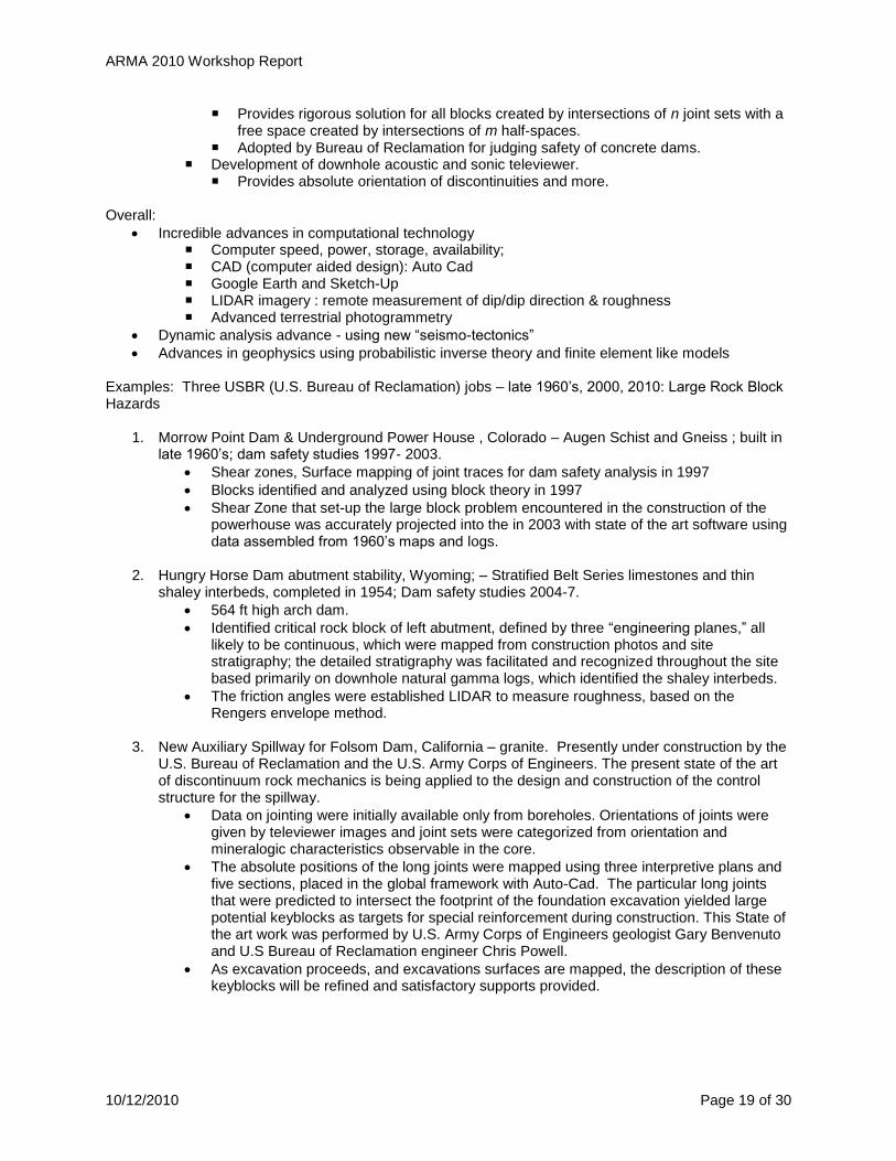
10/12/2010 Page 19 of 30
Provides rigorous solution for all blocks created by intersections of n joint sets with a free space created by intersections of m half-spaces.
Adopted by Bureau of Reclamation for judging safety of concrete dams. Development of downhole acoustic and sonic televiewer.
Provides absolute orientation of discontinuities and more. Overall:
Incredible advances in computational technology Computer speed, power, storage, availability; CAD (computer aided design): Auto Cad Google Earth and Sketch-Up LIDAR imagery : remote measurement of dip/dip direction & roughness Advanced terrestrial photogrammetry
Dynamic analysis advance - using new “seismo-tectonics”
Advances in geophysics using probabilistic inverse theory and finite element like models Examples: Three USBR (U.S. Bureau of Reclamation) jobs – late 1960‟s, 2000, 2010: Large Rock Block Hazards
1. Morrow Point Dam & Underground Power House , Colorado – Augen Schist and Gneiss ; built in late 1960‟s; dam safety studies 1997- 2003.
Shear zones, Surface mapping of joint traces for dam safety analysis in 1997
Blocks identified and analyzed using block theory in 1997
Shear Zone that set-up the large block problem encountered in the construction of the powerhouse was accurately projected into the in 2003 with state of the art software using data assembled from 1960‟s maps and logs.
2. Hungry Horse Dam abutment stability, Wyoming; – Stratified Belt Series limestones and thin
shaley interbeds, completed in 1954; Dam safety studies 2004-7.
564 ft high arch dam.
Identified critical rock block of left abutment, defined by three “engineering planes,” all likely to be continuous, which were mapped from construction photos and site stratigraphy; the detailed stratigraphy was facilitated and recognized throughout the site based primarily on downhole natural gamma logs, which identified the shaley interbeds.
The friction angles were established LIDAR to measure roughness, based on the Rengers envelope method.
3. New Auxiliary Spillway for Folsom Dam, California – granite. Presently under construction by the
U.S. Bureau of Reclamation and the U.S. Army Corps of Engineers. The present state of the art of discontinuum rock mechanics is being applied to the design and construction of the control structure for the spillway.
Data on jointing were initially available only from boreholes. Orientations of joints were given by televiewer images and joint sets were categorized from orientation and mineralogic characteristics observable in the core.
The absolute positions of the long joints were mapped using three interpretive plans and five sections, placed in the global framework with Auto-Cad. The particular long joints that were predicted to intersect the footprint of the foundation excavation yielded large potential keyblocks as targets for special reinforcement during construction. This State of the art work was performed by U.S. Army Corps of Engineers geologist Gary Benvenuto and U.S Bureau of Reclamation engineer Chris Powell.
As excavation proceeds, and excavations surfaces are mapped, the description of these keyblocks will be refined and satisfactory supports provided.

ARMA 2010 Workshop Report
10/12/2010 Page 20 of 30
Afternoon Session – The Future
Afternoon Session Comments by Bill Pariseau
Applications, Engineering – Needs (a personal view)
1. Caving – hardrock, block and panel extraction Common Factors and Needs: (innovation required) • No need to study equilibrium requirements, in kinematics, or material laws, • Needs:
• Rational methods of determining and assigning realistic material properties throughout necessarily discrete numerical models – need innovations and support for detail in 3-dimensions
• Caving is complicated by proximity to surface pits • Need to understand mechanisms to avoid by intelligent design (see Powerpoint slides to
illustrate the conceptsbelow) • Subsidence from block caving operations at the San Manuel Mine in Arizona • Drawpoint at Henderson Block Caving Operation • El Teniente - Underground – Surface Mine Interaction (block caving and open pit)
• Note the multiplicity of scales – from kilometers to meters
2. Longwall mining - softrock caving (photo showing shearer and shields to illustrate concept)
Solvay mine in Wyoming
3. Mine subsidence
underground-surface interactions
aquifers and ground water management
structures, support
4. Wide area catastrophic collapses
Solvay (trona) Wyoming, there was a magnitude 5.9 event in 1994 – no consensus on what caused it
Crandall Canyon (coal) Utah, more recent extreme event with tragic consequences
…many others, these extreme events occur more often than one might think
(Research: e.g., J. Whyatt, F. Varley, SRL/NIOSH, M. Board, Itasca)
5. Deep coal mine design, mine pillars • Current practical depth is about +2500 ft in the U.S (deeper abroad). • Overall extraction ratio is about 50% (traditional room & pillar, and longwall). • Many coal seams, large resources, exist below 2,500 ft. There are large reserves of coal
below 2,500 ft in Utah and elsewhere. • Current inter-panel barrier pillar design unsatisfactory
• Aberdeen Mine (UtahAmerican Energy, Inc.), e.g., to 3,000 ft – trouble with pillar ribs – the ribs need attention in deep coal mining.
6. Wet mine design, coupled hydro-mechanical phenomena
• Fundamentals of coupled hydro-mechanical behavior known • Concept of effective stress for strength and total stress for equilibrium understood • Need is for realistic assignment of material properties and hydraulic conductivities in
numerical models and faster, better models, e.g., • Kennecott Utah Copper, Bingham Canyon Mine, Utah – developed a successful drainage
(depressurization) system to improve stability. However, modeling did not match the observed response very well.

ARMA 2010 Workshop Report
10/12/2010 Page 21 of 30
7. EDUCATION
• Graduate engineers working in rock mechanics must understand the computer programs they select and use (or abuse).
• Too few engineers understand enough about geology or have sufficient training in this
important science.
• The requisite combination of continuum mechanics, applied mathematics, computer programming (not keystrokes!), with hands-on experience in laboratory testing and making mine measurements are all essential.
• Crandall Canyon, an example of education failure - computer abuse? • Boundary element programs were used, but BEM programs normally do not
include pillars in the solution. So BEM should not be used for pillar design • Without knowledge of pillar stress, pillar safety cannot be evaluated
objectively. • A simple finite element (FE) analysis with layer cake stratigraphy with
laboratory rock properties (if failure occurs in this analysis – it would surely develop in reality with lower strength rock mass) would show a dangerous mining plan. • Found yielding entries and barrier pillars in analysis – in fact, the roof did
not cave but the pillars blew out. • Computer programs used for design guidance should be fundamentally sound and
include the pillar in the analysis. • Stress equations of equilibrium satisfied? • Strain-displacement, kinematics satisfied? • Stress-strain laws, failure criteria based on experimental evidence and
realistic? • Boundary and far field pre-excavation conditions satisfied?
• Some computer programs meet these requirements for mine pillar design, some do not
• ELFIN, PLAXIS, ABAQUS, FLAC, UDEC, e.g. do • BEM codes, LAMODEL, ALPS, e.g., do not • Education needed!
• Fundamental questions remain: STEPS TOWARDS REALITY
• Heterogeneity of many scales? • Variability in rock properties? How to characterize variability and incorporate this in
models? • Equivalent properties? If so, use in a technically sound way. • Representative volume elements? • Random Numerical Methods – using random fields over a plane? May help with
variability? Other approaches – NRVE, Synthetic Roc Mass modeling? • Time-dependent characterization? Very little data to select a reliable model for long-life
design. • What to do about all those “joints”…? • Probabilistic approaches?
• Conclusions from Bill Pariseau
• Advances must come from team efforts – single investigator and graduate student in a study can‟t hope to make the needed contributions to advance engineering practice.
• Need larger, more comprehensive studies: laboratory testing, mine measurements, innovative numerical analyses, case studies, public data bases.
• Need cooperation amongst mining companies, research agencies, university departments, consulting firms.
• Issues for funding agencies.

ARMA 2010 Workshop Report
10/12/2010 Page 22 of 30
Afternoon Session Comments by Maurice Dussealt New Petroleum Geomechanics Challenges, Directions - three areas for focus:
Deep Waste Injection Geomechanics in CO2 Sequestration Geothermal Energy Extraction
These are three emerging areas that promise to be of great interest in the next 2-4 decades. Deep Waste Injection
Water disposal Saline produced water from oil wells (for each barrel of oil - > 3 barrels of contaminated
water are produced. We have been re-injecting the water in saline aquifers or using it for water floods
Other sources of non-usable water Injection below fracture pressure
Solids disposal – grind up solids and inject them Particulate (or pulverized) waste solids Biosolids (municipal sludges, pulp and paper operations black liquor, whey…) Injection must be above fracture pressure – so need rock mechanics
Water Disposal
Sedimentary basins contain huge volume capacity for water disposal Sediments (especially rocks with clay) act as filters and adsorbents for bacteria, viruses,
dissolved material Thermal effects may be important (cold water into a hot reservoir)
Cooling leads to small ΔV, hence Δσ as well Fracture pressures can change
Solids Disposal – solid waste slurries
A slurry of granular solids (<5 mm) and waste water is injected at depth Injection is by continuous hydraulic fracturing, injection pressure at the bottom of the hole -
pinj ~ 1.2·σv to 1.3·σv Filtration of solids, water dissipates into the porous medium, solids stay trapped under the
effective stress Massive changes in properties [Δσ], Δ(k, Cc) take place, dilation in jointed rock, creating
volume changes. In different directions joints close or open. The reservoir “evolves” with injection volume Uplift occurs, etc. (note – might be usable for geoengineering of coastal areas where sea
level rise is of concern - Venice) Ideal litho-stratigraphy for disposal: Flat or gently inclined strata with thick and continuous permeable zones and impermeable zones. Need barriers to upward migration, capacity to allow bleed water to move out, and solids remain reasonably near to injection points. Process Well Analyses – typical tests
• Minifrac • Initial fracture pressure & ISIP
• Injectivity Test • Radial flow characteristics of the formation
• Step Rate Test • Fracture Extension Pressure & Fracture Extension Rate
• Pressure Fall-Off Test

ARMA 2010 Workshop Report
10/12/2010 Page 23 of 30
• Formation permeability (estimated), skin • Components of fluid flow (such as linear flow, boundary condition effects, etc.)
Biosolids Injection - can approach Zero Discharge Injection.
Example: The World‟s First Biosolids Injection Site – Los Angeles, underground Injection Control Program Permit (Class V, Experimental Permit Number CA5060001).
Biosolids Injection Benefits
Risk reduction (no transport, etc…) GW protection (great injection depth) Soil protection from viruses, prions, chemicals, metals in the sludges… CH4 generation at depth (15% of dry mass) for energy recovery C sequestration (~40% of dry mass) in a zero-risk solid form Lower costs, less surface treatment…
Example from Los Angeles - Heavy metals, bioactive mass are not mobilized at 2,500 to 3,000 ft deep once overburden weight is on the solids. 15-16% of the dry mass gets turned into methane that can be drawn off for energy recovery. The CO2 will dissolve into water and the rest (40% of dry mass) can eventually be turned into “coal”. Need to monitor (including microseismic monitoring), view this as an experiment – enhanced understanding will allow us to manage the risks. The Geomechanics Issues
Site selection criteria [= ƒ(waste type)] Solids filtration and slurry flow theory Stress and fracture orientation changes Integrity of casing and environmental protection Monitoring solids injection:
p-σ-V-T-k monitoring and testing – these are not easy to model or monitor Deformation monitoring (real-time tilt) Microseismic monitoring
The Future
Zero liquid and solid waste discharge is now feasible in the Petroleum Industry Technology applicable to any solid waste (but only non-hazardous wastes to date) The security level for deep placement of solid waste is exceptionally high… For many wastes, deep injection is the lowest cost option The regulators need to be educated
CO2 Sequestration
Major CO2 point sources – synthetic crude and petrochemical sites, coal-fired power sites
Depth and CO2 State: we want to store the CO2 at the same pressure as the water. By depth of a little over 1 km, density of CO2 is about 700 kg/m
3 versus the density of gaseous CO2 at shallower
depth of less than 100 kg/m3, versus typical saline water density of 1.03 kg/m3 @STP (assuming a geothermal gradient of 25°C at the surface, hydrostatic pressure distribution with depth). So… to achieve volume-efficient storage in porous media, almost everyone believes in SuperCritical CO2 placement – SC-CO2 with the displacement of the pore water from the rocks.
T increases w. depth ~20-25ºC/km In most areas, T > 35ºC below ~800 m In cold conditions, pure CO2 will be in a liquid state In the presence of water and high p, a CO2-H2O clathrate (hydrate) forms
ARMA 2010 Workshop Report
10/12/2010 Page 24 of 30
Critical SC-CO2 Properties The viscosity of SC-CO2 is on the order of 1/20
th that of water. That means that in a very
small microfracture, it can flow 20 times faster than water under the same conditions. Storage density of SC-CO2 will likely be in the range 0.6-0.9 g/cm
3 versus the density of 1.05
for saline water – this density difference yields a huge buoyancy force – need strong geologic seals
SC-CO2 is miscible with H2O and also with oil Water will mix with the CO2 Capillary barriers may be affected
Options
Biosolids injection Coal seam injection (methane displacement) Salt cavern placement – need at least as temporary/interim storage before injection
Design issues Integrity Stability Security Safety Longevity (cavern closure to be expected in 1,000 to 4,000 years)
NaCl is a superb seal, but… Salt creeps, and the rate is a non-linear function of σ – pc So… pc - the cavern pressure - builds up slowly! As pc increases, risks increase Salt caverns will be excellent short-term storage facilities (<100 yr), but the risks are
too large for the long term. As pressure gets too high – you run the risk of hydraulic fracture
CO2 oil displacement CO2 storage in a saline aquifer, displacing gas: e.g., Krechba Algeria CO2 Storage Ocean injection
Geomechanics Issues
Restricting the discussion to sandstone reservoirs and shale seals… And, to supercritical phase injection… Long-term risks of escape are the issues
Seals are generally shales Stresses and pressures are important - Fluid migration is a function of stress as well
as pressure Slow dissolution in water Reservoir “Valving”, shearing, hydraulic fracturing Density Effect
Because of the lower density, there will always be a buoyancy force, promoting upward flow wherever possible
In cases where the lateral stresses are low, a tall column of SC-CO2 can lead to a significantly higher p at the top of the column
Fractures and Capillary barriers – many natural gas reservoirs are sealed because of capillarity – can sustain a significant pressure across the zone. Do you believe that the barrier to SC-CO2 will remain stable over geologic time?
CH4 – H2O have limited miscibility and a capillary barrier forms Such barriers are stable over geological time (shales – silts) SC-CO2 – H2O are mutually miscible Under what conditions can a capillary barrier be assured indefinitely? Shrinkage of Shale - what happens with clays that have adsorbed water –
will the water be stripped – generating shrinkage, and reducing the horizontal stresses. A small amount of shrinkage will reduce σh, generating conditions for hydraulic fracturing

ARMA 2010 Workshop Report
10/12/2010 Page 25 of 30
Proposed projects – include SpectraEnergy CO2 sequestration near the Fort Nelson gas processing plant in British Columbia.
Geothermal
Consider the heat flux map of the world and identify where it is sensible to consider heat extraction.
How to develop? Use hydraulic fracturing. Must maximize Q (flow rate)
Q = ƒ(Area) – need to maximize reservoir contact via horizontal wells More area = more fractures. What is the shape of the hydraulic fractures – how to model
real shapes? Will develop cooling-induced fractures as extraction progresses - “Daughter” fractures
propagate at 90° to the mother fracture, heat exchange becomes better. Effects of Natural Fractures
Locally, fractures follow fabric; globally, they follow stresses Pyrolysis Effects and Fractures - ΔT & ΔV, gas generation, vaporization,
condensation of water and pyrolysis products, gravitational phase segregation cause density-driven reflux and convective heat transfer, etc.
Get ΔT-induced aperture dilation and k increase improve fracture flux Extensional strain may open overlying vertical joints, impairing vertical
fluid seal Other effects
Reservoir – Hot Dry Rock Seismicity Geyser-induced Seismicity - Local clustering of micro-earthquakes around most injection
wells. Timing: seismicity lags injection by days, weeks, a few months. Limited to M<3.0. Earthquake Movements (e.g., Bam, Iran) – InSAR used to identify differenced
ground movements, show quadrupole configuration associated with the shear displacement event
Subsidence/heave: InSAR Interferograms used to study ground subsidence from ground water withdrawal in the area of Phoenix, AZ. Other examples: Imperial Oil – Cold Lake (subsidence and heave to 285 mm heave and 210 mm subsidence over 86 days), Belridge Field, CA (diatomite subsidence, rate up to 20 to 25 inches per year)
Banjarpanji, East Java, Indonesia – lost a well and created a mud volcano (August 2007). Tried a relief well.
Summary from Maurice Dusseault
Comments on Petroleum Geomechanics
Clearly, we still have lots to learn… We CHANGE the stresses, coupled to ΔT, Δp, ΔV, even chemistry changes… Implications and applications of stress changes are huge! Use of massive data banks that are now being developed:
Whole Earth Geomechanical Models Fractured rock geomechanics
How do we simulate fractured rock being subjected to ΔT, Δp, Δσ‛? How do we couple our geomechanics models to fluid flow? Δρ- & Δp-driven? What about the geomechanics effects of high T?? Clay dehydration, kerogen
pyrolysis in oil shale…? What about drilling in HPHT geologic materials?
Could we have avoided the Gulf of Mexico (Deep Water Horizon) case?
The Indonesia mud volcano?

ARMA 2010 Workshop Report
10/12/2010 Page 26 of 30
Afternoon Session Comments by John Curran Going Forward: What Can We Do? Can We Improve Characterization?
Can we measure the inputs needed for numerical modeling? We need to know where the joints are, and something about their spatial distribution.
o Better characterize fracture networks, joint stiffness and strength – we don‟t have firm methods, just generally rules of thumb
Can we keep better records? o We need organized, well-kept, electronic records/data across projects – pooled data
resources Can We Improve Brittle Rock Modeling - Common in many rock engineering situations, and it is a difficult problem. Example – Niagara Falls large tunnel – fracture/spalling is developing a notch - $450 million impact for project.
Can we better model the range of brittle fracture behaviors? o Brittle failure initiation o Propagation of fractures after initiation o Behavior after failure – spalling, buckling, progressive failure, etc.
Potential of application of discontinuous numerical methods
Development of improved constitutive models – and take into account that the properties are changing, and the heterogeneities that generate the stress concentrations.
Can We Better Apply Numerical Tools?
Can we progress towards quantitative predictions? o Need field measurements + back-analysis for in situ properties
Can we determine how efficient our designs are? o Need field measurements and monitoring in order to assess by how much we over-
design? Can We Better Capture Variability?
We need to be able to model material property and geometry uncertainty and spatial variability
Must investigate application of o Use conventional statistical approaches o Geostatistics/Random Field Theory – resolution of tension between using „averaged‟
values and „discrete‟ values at different locations o Risk management techniques
Thoughts on Implications of Discrete Fracture Network models
Need for multiple realizations
Appropriately scaled block properties
Other Comments:
Hydraulic conductivity: Saturated/unsaturated has been in the models. John cannot think of a single person who has made testing to evaluate unsaturated permeability – it is clearly not equal to saturated permeability.
Not enough people have actually taken FE courses, so they do not really understand the models and constraints, cautions. E.g., what is a good mesh, what should the boundary conditions be? Does the analysis make sense?
ARMA 2010 Workshop Report
10/12/2010 Page 27 of 30
Afternoon Session Comments by Dick Goodman
“Twenty Twenty Vision: Some issues that needs to be addressed and solved by the year 2020”
1. We need continuing reality checks and updating for rock mass properties that are assigned using rock mass classification systems. Design from rock classification seems the easy thing to do, but can give us answers that are wrong or incomplete. All these variously useful empirical systems that are providing input for analytical and numerical models need a continuous dose of relevant back-calculations and appropriate readjustments based on:
o real performance records, o lab tests of samples, and field tests if we can ever get them o the local geology - - formation, rock classification, structure, and geomorphology.
Then we will be able to increase trust in these tools.
2. The accelerating development of computational models, methodologies, and products has enormous potential for improving our art and science. The rock mechanics community should stay highly informed and involved and continue to take full advantage of computational developments and new tools. This has obvious implications for education, research funding, and engineering practice.
Large modeling programs like Dyna3d, and visualization programs are so complex that their operation tends to be left to specialists.
Thus we can get carried away by beautiful results even if the output fails to take advantage of fundamental rock mechanics capabilities. For example, we have to compute block failure modes and factors of safety (or probabilities of failure), not just look at impressive 3-dimensional pictures of outcrops and moulds of missing blocks.
The answer is for our profession to guide hardware and software innovations with respect to our needs by participating in their development. We need their products, and they need our expertise.
Let the philosophy of Arthur Schopenhauer guide our understanding of the present turmoil between those who would move immediately to embrace all the new methods, and those who stand reluctant to give up their tried and tested technology:
All truth passes through three stages. First, it is ridiculed; Second, it is violently opposed, Third, it is accepted as being self-evident. As the biggest library , if it is in disorder, is not as useful as a small but well-arranged one, so - - - you may accumulate a vast amount of knowledge, but it will be of far less value than a much smaller amount if you have not thought it over for yourself.
3. Methodologies for the increasingly popular risk-analysis-based decision-making must assure that it is the engineer, not the computer, who makes the decisions.
Rock and rock problems can be fuzzy.
Computers lack common sense and intuition.
Thus computations for rock problems can suggest imperfect, or unreasonable responses.

ARMA 2010 Workshop Report
10/12/2010 Page 28 of 30
Comments by Chuck Dowding “Thoughts on the Future of Urban/Civil Needs in Rock Mechanics“
• The Future is Underground for Congested Urban Infrastructure Development Example: 9$ Billion for increasing limited NJ-NYC commuter rail capacity
• Site investigations
• Directional drilling needs to be adapted for exploration in civil/urban applications.
• Too little application of geophysics.
• 3-dimensional subsurface modeling - Interpolation between boreholes, integrated with subsurface infrastructure and above ground facilities for an urban model to support sustainable planning.
• Design
• Need to bring the social context in
• Need to develop broadly accepted methodology for bringing sustainability and resilience into life-cycle design
• Need to contract in a way the is friendly to new technologies and methods
• Rock is Difficult and Expensive to Excavate in an Urban Environment
• Often control blasting, explosive fragmentation is the least expensive alternative (reference: ARMA/NSF 2000 Workshop: Underground Urban Rock Construction) http://www.armarocks.org/Bookstore/ but need to respond to public concerns about sensitivity to vibration.
• Urban Mass Transit is Expensive: We have met the enemy and they are us!!
• 98 % of those surveyed said that they preferred mass transit for someone else
• More people own pickup trucks than use mass transit
• Price of 1 gallon of gasoline (in $US 2010)
Belgium France Germany UK US
6.36 6.11 6.53 5.53 2.47
• Why has the Federal Government propelled Chrysler-Fiat to bet the bank on fuel stingy engines when Federal policy doesn‟t discourage consumption?
• Policies that increase private transit efficiency allow increased use of private transit which allows more suburban sprawl and increases need for private transit (Jevon‟s Paradox)
• Critically Needed Improvements in Excavation
• Prediction of penetration rates: 1 m TBM to test cutter head performance
• Innovative means of rock cutting: vibratory disks, water-jet assisted disk cutting
• Directional drilling: coiled casing, reduce max radius of curvature
• Controlled blasting: auto feedback loops (penetration rate – blast loads, vibrations – fragment size)
• Specific energy to explosively fragment: gas pressure vs shock
• Alternative technologies: Alternate Technologies: trenching, sawing, splitting (mechanical, chemical)
• We need to adopt a culture that knows how to characterize and incorporate variability and uncertainty in design so that risks can be identified and managed in the contract, and identified for research. This is very important for credibility of the engineering and construction process with the public and political communities that we need to engage.
• To Peer into Future --- Think Logarithmically
• Example: The Internet came out of nowhere. Even though we tend to extrapolate linearly or arithmetically, technological growth is often exponential.

ARMA 2010 Workshop Report
10/12/2010 Page 29 of 30
• Miniaturization and Computerization
• Computation will decline in price and increase in speed exponentially, which will spark unimaginable developments, e.g., the Electronic Blasting Cap which has resulted in
• Reduced potential timing errors by orders of magnitude by incorporating microprocessors into the delay sequence
• Increased security
• Improved fragmentation
• As a second example: Mine to Mill Fragmentation Tracking
• Autonomous visual (camera and RFOD) tracking
• Which allows real time truck identification - batch identification
• Photographic analysis of particle size distribution (image analysis)on the trucks – post primary – post secondary
• http://www.spliteng.com/downloads/Pit
• Complete Simulation of Complex Phenomena with coupled process, discrete models, e.g., HSBC Hybrid Stress Blasting Code
• We musn‟t forget Nano: the frontier of miniaturization
• Look for future applications like a Down Hole Condition Communication capability
• Combine devices with RIF sensors (e.g., like recent development of this capability in artificial red blood cells” called Respirocytes). http://www.kurzweilai.net/
• Pump down and retrieve
• Water is the Next Oil - Water price policy and public perception are not aligned
• Price of Lake Michigan Water from my tap: $ 0.002/gallon; price of Lake Michigan Water from a plastic bottle: ~ $ 2.000/gallon
• According to Brita, its high-end faucet filter system provides water for 18 cents a gallon, a considerable saving from $1 or more typically charged for an 8- to 12-ounce bottle of water.
• A recent survey of 14 countries indicates that average municipal water prices range from 66¢ per cubic meter (0.002$/gal) in the United States up to $2.25 in Denmark and Germany. Yet consumers rarely pay the actual cost of water. In fact, many governments practically (and sometimes literally) give water away for nothing. (Earth Policy Institute 2007)
• Water deficits may develop in Metropolitan Chicago – reference the 1985 Great Lakes Charter which requires prior notice of any diversion outside of basin that exceeds 5,000,000 gal/day average over 30/days, and that information also be gathered on all diversions> 100,000 gallons/day. http://www.cglg.org/projects/water/docs/GreatLakesCharter.pdf
• We need to envision a grand-challenge-type problem for significant and multi-year investment in research. Something similar to the NSF-funded NEES (Network for Earthquake Engineering Simulation) program.

ARMA 2010 Workshop Report
10/12/2010 Page 30 of 30
Overall Summary from the Workshop
What do we need to achieve?
1) Involvement in important larger issues that will be compelling for sustained funding and progress toward solution.
a. Defense b. Global climate change (energy, sequestration, geothermal) c. Environmental protection (waste, water) d. Resource production (petroleum and gas, ore and thermal mining, water resources)
2) Contributions toward improved life-cycle design and more efficient construction for sustainable
and resilient underground space, particularly in urban areas. a. Advances in site characterization, interrogation of the subsurface (including geophysical
methods) b. Advances in excavation and support c. Geologic information modeling
3) Advanced understanding of rock mass properties and behavior
a. Computational simulation (DFN, SRM) using enhanced modeling capabilities, with rock mechanics professionals being involved in model developments
b. Experimentation and observation c. Calibration and validation of models d. Understanding impacts of scale in terms of time and spatial dimensions e. Coupled processes
4) Continued definition of the global geologic stress field, providing important input for geoprocess
modelling and development of validated computational models applicable at great depth with high pressure and temperature conditions.
5) Relating our observational models (e.g., RSR, RMR, Q, GSI) to the computational models and to
field testing and observation. We need to establish where/in what way to have confidence in these models.
6) Capture geologic heterogeneity, variability and uncertainty in design and application
a. Probabilistic models b. Risk based methods
7) Understanding extreme events (e.g., earthquakes/seismicity) – initiation mechanisms, unfolding
processes, impacts, response and recovery, and how rock mechanics and engineering can contribute to addressing these vulnerabilities.
8) Recruiting the best students, offering the best curriculum and opportunities (and include geology
and numerical model training in the graduate coursework, and undergraduate if possible).
9) U.S. academics and practitioners need to be more effective in engaging the international rock mechanics and engineering communities. There is much excellent work going on outside our borders, and if we can create and extend strong personal and intellectual connections we will be able to build U.S. leadership in all applications of rock mechanics and engineering.
Advances in each of these areas must come from team efforts because larger, more comprehensive studies are needed including laboratory testing, mine measurements, innovative numerical analyses, case studies, and development of public data bases and collaboratory portals for inquiry. This requires cooperation amongst mining companies, research agencies, university departments, and consulting firms. Funding agencies should be so advised by ARMA, e.g., more S-4/DUSEL-type collaborations.