the effects of residual tensile stresses induced by cold ...€¦ · the effects of residual...
TRANSCRIPT

The Effects of Residual Tensile Stresses Induced by Cold-Working a Fastener Hole
A. Brot and C. MatiasEngineering Division
Israel Aerospace Industries
Presented to the:USAF Aircraft Structural Integrity Program (ASIP)
ConferencePalm Springs, CA
4 December 2007

ASIP 2007, Palm Springs, CA Unclassified
2
Photoelastic Measurements of the Stress Field at a Cold-Worked Hole (provided by Fatigue Technology Inc.)

ASIP 2007, Palm Springs, CA Unclassified
3
Crack Growth from a Notched Edge towards a Cold-Worked Fastener Hole for 7475-T7351 Aluminum Alloy(detail was cut-away from a component test specimen)
10mm Radius Edge
Cold-Worked Fastener Hole

ASIP 2007, Palm Springs, CA Unclassified
4
Test Specimen Used to Measure Residual Stresses Induced by Cold-Working (10mm notch radius)
Fastener Hole

ASIP 2007, Palm Springs, CA Unclassified
5
Measured Stress Distribution along Edge of Notch
Cold-Work Residual Stress Along Edge With Radius 10mm; Opposite of c'sink side; Hole #2
-5
0
5
10
15
20
25
30
-2 -1 0 1 2 3 4 5 6 7 8 9 10X Coordinate [mm]
Res
idua
l Stre
ss [k
si] C W Stage
C'Sink Stage
X = 0X
Cold-Work Residual Stress Along Edge With Radius 10mm; C'sink side; Hole #2
-5
0
5
10
15
20
25
30
-2 -1 0 1 2 3 4 5 6 7 8 9 10X Coordinate [mm]
Res
idua
l Stre
ss [k
si]
C W StageC'Sink Stage
X = 0X
Cold-Work Residual Stress Along Edge With Radius 30mm; Opposite of c'sink side; Hole #2
-5
0
5
10
15
20
25
30
-2 0 2 4 6 8 10 12 14 16 18 20 22X Coordinate [mm]
Res
idua
l Stre
ss
C W StageC'Sink Stage
X = 0X
Cold-Work Residual Stress Along Edge With Radius 30mm; C'sink side; Hole #2
-5
0
5
10
15
20
25
30
-2 0 2 4 6 8 10 12 14 16 18 20 22X Coordinate [mm]
Res
idua
l Stre
ss
C W StageC'Sink Stage
X = 0X

ASIP 2007, Palm Springs, CA Unclassified
6
Stress Field around a Cold-Worked Hole near an Edge (e/D = 1.95) showing a residual stress of about 31 ksi.
Elastic-plastic (ABAQUS) FEM, using quadratic reduced integration, courtesy of Fatigue Technology Inc.
ABAQUS FEM mesh

ASIP 2007, Palm Springs, CA Unclassified
7Test Results for the 30mm Radius Coupon with Cold-
Worked and Countersunk Holes
• Failure of a 30mm radius test coupon under 20 ksi (R = 0.05) loading.
• Failure originated from the outer diameter of the countersunk holes.
• Mean life of first failure(3 coupons, 12 holes): 186,000 cycles.
30mm Radius

ASIP 2007, Palm Springs, CA Unclassified
8Test Results for the 10mm Radius Coupon with Cold-
Worked and Countersunk Holes
• Failure of a 10mm radius test coupon under 20 ksi (R = 0.05) loading.
• Failure originated from the 10mm radius edge, adjacent to the cold-worked hole.
• Minimum life (1 coupon, 4 holes): 57,000 cycles.
10 mm Radius
Origin

ASIP 2007, Palm Springs, CA Unclassified
9
Symmetryplane
Symmetryplane
P-level DOF
Total Potential Energy
Convergence Rate
% Error
1 119 1.230594E+03 0 31.35
2 342 1.131074E+03 1.11 9.72
3 579 1.125535E+03 0.7 6.71
4 920 1.121601E+03 1.63 3.15
5 1365 1.120756E+03 1.81 1.54
6 1914 1.120553E+03 2.11 0.76
7 2567 1.120506E+03 2.23 0.39
8 3324 1.120494E+03 2.23 0.22
52 Elements, p = 8, nonlinear solution
StressCheck (ver. 7.1) Analysis of Cold-Worked Specimen
Quarter Model
ASIP 2007, Palm Springs, CA Unclassified
10
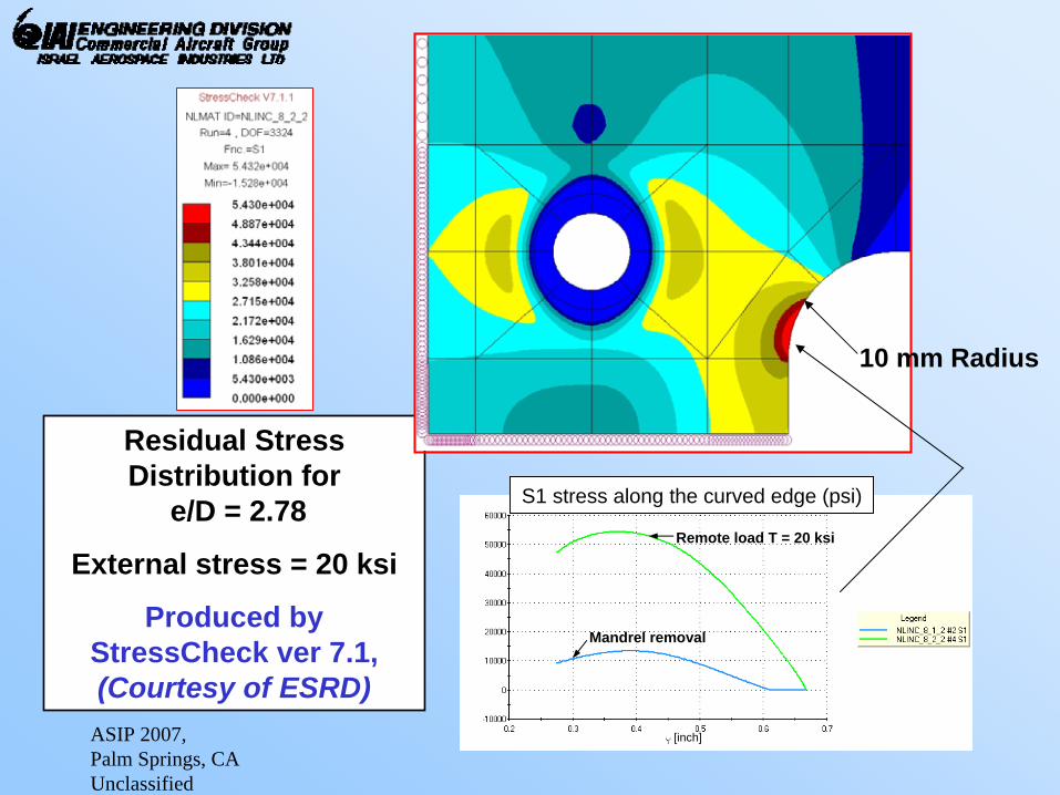
Residual Stress Distribution for
e/D = 2.78
External stress = 20 ksi
Produced by StressCheck ver 7.1, (Courtesy of ESRD)
S1 stress along the curved edge (psi)
Mandrel removal
Remote load T = 20 ksi
10 mm Radius
[inch]

ASIP 2007, Palm Springs, CA Unclassified
11
Comparison of Measured Stresses and those Calculated by the StressCheck (ver. 7.1) FEM
Notch stresses after cold-working (no external loading)
Notch stresses after application of 20 ksi stress
Cold-Work Residual Stress Along Edge With 10mm Radius; e/d = 2.78; CW Expansion = 3.89%
-2
0
2
4
6
8
10
12
14
16
18
20
-2 -1 0 1 2 3 4 5 6 7 8 9 10
X Coordinate [mm]
Res
idua
l Str
ess
[ksi
]
SG measurements
STRESSCHECKFEM Analysis
X = 0X
20ksi Remote Loading + Cold-Work Residual Stresses Along Edge With 10mm Radius; e/d = 2.78; CW Exp. = 3.89%
-5
0
5
10
15
20
25
30
35
40
45
50
55
60
-2 -1 0 1 2 3 4 5 6 7 8 9 10
X Coordinate [mm]
Res
idua
l Str
ess
[ksi
]
SG measurements
STRESSCHECKFEM Analysis
X = 0X
ASIP 2007, Palm Springs, CA Unclassified
12
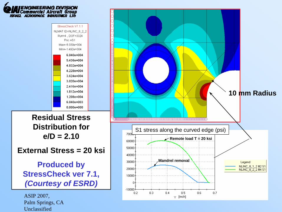
Residual Stress Distribution for
e/D = 2.10
External Stress = 20 ksi
Produced by StressCheck ver 7.1, (Courtesy of ESRD)
S1 stress along the curved edge (psi)
Mandrel removal
Remote load T = 20 ksi
10 mm Radius
[inch]

ASIP 2007, Palm Springs, CA Unclassified
13
Photoelastic Measurements of Residual Stresses at the Edge Resulting From Cold-Working
(performed by Vishay Israel Ltd.)

ASIP 2007, Palm Springs, CA Unclassified
14Measured and Calculated Residual Stresses at the
Edge, Resulting From Cold-Working
0
5
10
15
20
25
30
35
1.90 2.00 2.10 2.20 2.30 2.40 2.50 2.60 2.70 2.80 2.90
Edge distance / Starting hole Diameter
Res
idua
l Str
ess
[ksi
]R=30mm; 3.89%
R=10mm; 3.89%Straight edge 4.26%
R=10mm; 3.1%R=30mm; 3.1%
Abaqus FEM analysis for straight edge 4.26%STRESSCHECK FEM analysis for R=10mm 3.89%

ASIP 2007, Palm Springs, CA Unclassified
15
Superimposing of Notch Stresses with the Residual Stresses
e
d
Cold-workedhole
Residual Stresses
Notch stress due to external loading: σnotch = σ x Kt
σ
σ
σtotal = σ x Kt + σresidual

ASIP 2007, Palm Springs, CA Unclassified
16
Fatigue Analysis Results for 7075-T7351 Aluminum alloy:(superimposing notch stresses (R = 0) with residual stresses)
20
25
30
35
40
45
50
1.E+03 1.E+04 1.E+05 1.E+06 1.E+07Mean Fatigue Life (cycles)
Max
imum
Not
ch C
yclic
Str
ess
[R=0
] (ks
i)Residual Stress: 0 ksi
Residual Stress: 10 ksi
Residual Stress: 20 ksi
Residual Stress: 30 ksi
30mm radius, e/D = 2.66
Mean Test Fatigue Life > 186,000 cycles
(failed at CW hole)

ASIP 2007, Palm Springs, CA Unclassified
17
Fatigue Analysis Results for 7075-T7351 Aluminum alloy:(superimposing notch stresses (R = 0) with residual stresses)
20
25
30
35
40
45
50
1.E+03 1.E+04 1.E+05 1.E+06 1.E+07Mean Fatigue Life (cycles)
Max
imum
Not
ch C
yclic
Str
ess
[R=0
] (ks
i)Residual Stress: 0 ksi
Residual Stress: 10 ksi
Residual Stress: 20 ksi
Residual Stress: 30 ksi
30mm radius, e/D = 2.66
Mean Test Fatigue Life > 186,000 cycles
(failed at CW hole)
10mm radius, e/D = 2.78
Test Fatigue Life = 57,000 cycles

ASIP 2007, Palm Springs, CA Unclassified
18
Fatigue Analysis Results for 7075-T7351 Aluminum alloy:(superimposing notch stresses (R = 0) with residual stresses)
20
25
30
35
40
45
50
1.E+03 1.E+04 1.E+05 1.E+06 1.E+07Mean Fatigue Life (cycles)
Max
imum
Not
ch C
yclic
Str
ess
[R=0
] (ks
i)Residual Stress: 0 ksi
Residual Stress: 10 ksi
Residual Stress: 20 ksi
Residual Stress: 30 ksi
30mm radius, e/D = 2.66
Mean Test Fatigue Life > 186,000 cycles
(failed at CW hole)
10mm radius, e/D = 2.78
Test Fatigue Life = 57,000 cycles
10mm radius, e/D = 2.10

ASIP 2007, Palm Springs, CA Unclassified
19
Fatigue Analysis Results for 7075-T7351 Aluminum alloy:(superimposing notch stresses (R = 0) with residual stresses)
20
25
30
35
40
45
50
1.E+03 1.E+04 1.E+05 1.E+06 1.E+07Mean Fatigue Life (cycles)
Max
imum
Not
ch C
yclic
Str
ess
[R=0
] (ks
i)Residual Stress: 0 ksi
Residual Stress: 10 ksi
Residual Stress: 20 ksi
Residual Stress: 30 ksi
30mm radius, e/D = 2.66
Mean Test Fatigue Life > 186,000 cycles
(failed at CW hole)
10mm radius, e/D = 2.78
Test Fatigue Life = 57,000 cycles
10mm radius, e/D = 2.10
No notch, e/D = 2.10

ASIP 2007, Palm Springs, CA Unclassified
20
SUMMARY AND CONCLUSIONS
1. Testing and analysis confirm that high tensile residual stresses can exist at an edge near a cold-worked hole.
2. These induced residual stresses are a function of:a. edge-distance to hole diameter ratio
b. level of mandrel interference
c. whether the fastener hole was final reamed and countersunk
d. fit of the fastener that is installed in the hole

ASIP 2007, Palm Springs, CA Unclassified
21
SUMMARY AND CONCLUSIONS
3. When these residual stresses are combined with high cyclic notch stresses that arise from external loading, the fatigue life at the edge can be drastically reduced. This should be accounted for in the design of details near a cold-worked hole.
4. Additional analysis and testing is needed to further quantify these effects.
[To receive a copy of the written paper, please contact me at [email protected]]
ASIP 2007, Palm Springs, CA Unclassified
22
ACKNOWLEDGEMENT
• The authors would like to thank Len Reid, Vice-President R&D at Fatigue Technology Inc., for his assistance and suggestions in studying this phenomenon and for Tom Poast for performing the elastic-plastic (ABAQUS) finite-element analyses.
• The authors would also like to thank Dr. Ricardo Actis and Dr. Sebastian Nervi of ESRD Inc., for performing the elastic-plastic (StressCheck ver 7.1)finite-element analyses.