the effect of neutral earthing practices on lightning ... · the effect of neutral earthing...
TRANSCRIPT
IEEE Transactions on Power Delivery, Vol. 13, No.3, July 1998 783
The Effect of Neutral Earthing Practices onLightning Current Dispersion in a Low-Voltage Installation
Arshad Mansoor, Member,IEEEPowerElectronicsApplicationsCenter
KnoxvilleTN37932USA
Abstract - Computer modeling with the EMTP code has beenapplied to several configurations and earthing practices in use invarious countries to show the effect of any differences in thedispersion (sharing)of a lightning stroke current among the availablepaths for the earth-seeking lightningcurrent. Simplifying assumptionshave been made to some details of the configurations to focus on themain difference --earthing practices. Identifying such differencesprovides the necessary perspective on their significance and the strongneed to take them into consideration when developing internationalstandards on surge-protective device applications.
I. INTRODUCTION
When designing a lightning protection scheme for a low-voltage power system within a building, several scenarios mustbe considered for the point of termination of the lightningstroke. Common wisdom classifies these by decreasing orderof severity: directly to the building, directly to overhead low-voltage distribution lines (or other utilities) outside of thebuilding, to other objects near the building, distant cloud-to-earth strokes, and finally perhaps cloud-to-cloud discharges.Several standards-writing projects are underway, at the IEEEand at the IEC, based on present knowledge of the lightningflash characteristics and on assumptions about the way thelightning current divides among the many paths available fordistributing (dispersing) this current to the ill-defined "earth"which is the termination of the cloud-to-earth strike.
The purpose of our paper is to show the effect that differ-ent practices for neutral earthing in the low-voltagedistributionsystem can have on the relative dispersion of the lightningcurrent which is seeking the path of least impedance to earth.
*Electricity Division, Electronics and Electrical Engineering Labo-ratory, TechnologyAdministration, Us. Department of Commerce.
PE-968-PWRD-O-05-1997 A paper recommended and approved by theIEEE Surge Protective Devices Committee of the IEEE PowerEngineering Society for publication in the IEEE Transactions on PowerDelivery. Manuscript submitted January 2, 1997; made available forprinting May 23, 1997.
Fran~ois Martzloff, LifeFellow,IEEENational Institute of Standards and Technology*
Gaithersburg MD 20899 USA
To accomplishthis purpose in an eight-page paper, and toconcentrate on the essential difference, the models we presentare simplified from the detailed reality, so that one of our firsttasks will be to explain and justify the simplification. To avoidconfusion in the meaning of the word "distribution" which canrelate to the distributionof electric power by the utility or to thedistributionof the lightning current among the available paths,we will use the term "dispersion" for the second meaning,lightingcurrentdispersion. Another term used by some authorsto convey the concept is "sharing" (among available paths).Note that the actual return stroke actually goes from earth tocloud in the majority of cases, but the scenario is generallydescribed as if the stroke "terminated" on earthbound objects.
In the case of a low-voltage power distribution system,differentcountries have adopted different practices on earthingthe neutral conductor, and writing a history of why that is sowould give an interestinginsight into the development of powersystems. The fact is that today, two approaches are wellentrenched in their respective territories, the so-called TNsystem and IT system where the difference lies in the mode ofearthing the neutral. We will give a brief overview of thedifferencesin a followingsection. Our purpose is to show howthe difference in these practices affect the sharing, ordispersion,of the lightningcurrent among the available pathstoearth, and consequently affect the rating of surge-protectivedevices which may be included in these paths. We used theEMTP simulation code [1] to model several scenarios in eachof the TN and IT systems, with small but possibly significantdifferences in the configuration. By postulating a direct stroketo one building, and requesting EMTP to compute currents inthe (simplified)complete power system, we obtained results forthe two most severe cases of lightning termination: the case ofa direct stroke to one building, and the case of a nearby strokewhich propagates and impingesat the service entrance of manybuildings on that part of the low-voltage distribution system.
The literature and draft standards contain many examplesof such scenarios, but it seems that each is confined to aspecific approach or power system configuration with fairlydetailed arrangements of load connections. The result is thatfrom this plurality of examples, it is difficult to extract a clearperceptionof the significantparameters in the dispersion of thelightningcurrent resultingtrom different earthing practices. Inthis paper, we will simplify the scenarios to concentrate on thefundamentaldifference between the neutral earthing practices.
0885-8977/98/$10.00 @ 1997 IEEE
784
II. THE TT AND THE TN SYSTEMS
The IEC has promulgated a letter code system describingthe arrangement of the neutral earthing in single-phase andpolyphase power systems [2]. For the purposes of our paper,we can summarizethe IT system as being a distributionsystemwhere the neutral is earthed only at the distributiontransfonnersecondary, and the protective earth in a building is obtainedfrom a local earth electrode. This system is used in somecountries. The TN system has its neutral earthed at anyavailable opportunity outside of a building, including thedistribution transfonner secondary, some or all poles, and theservice entrance. In the United States, an "EquipmentGrounding Conductor" (EGC) is created at the serviceentrance,bonded to the incoming power system neutral and tothe common local earthing point, after which the neutralconductor and the EGC are carefully(and by mandate from theNational Electrical Code [3]) kept separate from one another.
III. NECESSARY SIMPLIFICATIONS
Another difficulty in making a detailed comparison ofresults from different authors is that different models are oftenused. When apparently different results are reported, alingering question is that of differences attributable to thesimplifying assumptions and possible modeling artifacts. Wehave used the well-known EMTP code [I] for which ourprevious experience in cross-validation between the computermodel and full-scale experimental measurements [4], [5] gaveus great confidence in the validity of the results.
The literature offers many contributions on the systemsimulationbut our purpose is not literaturereview --again, ourpurpose is only to focus on the neutral practicesconsiderations.However, to support some of our postulates, we will cite somepapers to show that in the maze of assumptions,simplifications, and simulations, we are not alone.
A. Down-conductor representation
Some authors have included in their modeling a down-conductor feeding the stroke current to the common bondingpoint of the building [6]. In our model, since we postulate thatthe current is delivered froma current source, the impedanceofthe down-conductorhas no effect on the current being injectedat the common bonding point which is the point at whichdispersion (sharing) begins. Therefore, we did not include adown-conductor in our models.
B. Earthing impedance as afunction of time and current
Some authors consider the fact that the exact value of theearthing impedance is variable as a functionof time and currentlevel. For instance, [6] initially proposes a model involvingresistance, capacitance, and inductance,with some dependencyon time or current, or both. But after studying the problemcloser, the authors of [6] conclude that a reasonable approxi-mation is merely a fixed 10-Q resistance. We have used thisvalue in our models of the buildingearthing, and postulated animproved, lower 5-Q resistanceat the earthing electrode of thedistribution transfonner.
C. Other available current paths
Some standardproposals include telephone, water and gasconnections as possible paths for the earth-seeking lightningcurrent. Considering that the telephone service is a balancedsystem nonnally isolated from earth (until a network interfacedevice becomes involved),that some water and gas services caninclude a cathodic-protectionisolation or be implemented withplastic pipes, we chose a conservative approach of notincluding these as additional paths to earth.
D. Actual Circuit Configuration for Service Entrances
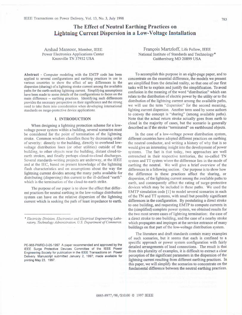
Figure I shows a schematic of a single-phase 3-wire TN120/240-V service to a building. One surge-protective device(SPD) is connected between each of the two lines and thecommon earthat theservice entrance, ignoring any SPDs withinthe building under the assumption that in a well-coordinatedcascade [7] the majority of the current is carried by the serviceentrance SPD which has the lowest limiting voltage in theinstallation. The stroke current, postulated to have tenninatedon a point of the earthing system of the building, can seek apath to earth in two ways: directly through the earth electrodeof the building, and by means of the three conductors backtoward the power system.
EGG
Figure 1. Service connections in a 3-wire TN system
Figure 2 shows a schematic of a three-phase 4-wire IT230/400-V service to a building. A dedicated protective earth iscreated and connected to a local earth electrode, while theincomingneutralof the power distribution system isnot bondedto this protective earth. At the service entrance, SPDs areconnected between the local earth and each of the incominglines and the neutral.
100~
PE
Figure 2 - Service entrance connections in a 3-phase, 4-wire TT system
E. Postulated lightning stroke current
While some authors propose a 200 kA, 10/350 JlSsurge[8], [9],others suggest that even a 100 kA peak might alreadybe too high a value [6], [10], [11]. In agreement with the latterthree references, we postulated a 100kA peak, 10/350Jlssurgecurrent. This selection also offers the convenience that whenwe report current levels in kiloamperes in the various circuits,the numbers also represent the percentage of the sharing,making it easier to follow the process. Since many standardsfor surges impinging on SPDs (at the service entrance) are stillbased on an 8/20 JlScurrent waveform, we will also show oneexample of the energy deposition in the SPDs when such an8/20 JlSsurge is postulated.
The surge currents are modeled using the EMTP Type 60Slave Source. Using the "Freeform FORTRAN" expression,any surge current waveform that can be expressed as a closed-form equation can be used as signal source in the main EMTPprogram. The equations for the 10/350 JlSand 8/20 JlSwave-forms with a 100 kA peak are respectively (I) and (2) below:
10/350 Jls: 1(1) = [//1]J {exp(-t/, J - exp(-t/,~J (1)where II'= 100 kA
1] = 0.9542'I = 480,} = 4
8/20 Jls: I(t) = A ~Jf exp(-t/r) (2)where I" = 100 kA
A = 0.01243,=3.911
(In both equations, t and rs are in ~s; I(t) is in same units as II')
F. Influence of Distribution Transformer Simplification
The presence of distribution transformers has beenincluded in many models in the literature, but their character-isticsare not the same among authors. Some authors have useda coupled inductor with parasitic capacitor to represent theinter-winding capacitor in the transformer model [12].
While these models are more accurate in studying trans-former failure modes due to low-side surges, for our mainfocus which is current dispersion among available paths, wehave chosen the simple model postulated in [8] of a simpleinductor to represent the winding. As results show, thepresence of a transformer at the far end of a daisy-chain low-voltage distribution system does not have considerable effecton the results. Therefore, we feltjustified in adopting the sametransformer model as described in [8] for all of our circuitconfigurations.
G. Simplifying the Circuitfor Modeling
The circuit impedances have been modeled in EMTP usingdiscrete components. The wiring between buildings and frombuilding to transformer is modeled as a series inductance withthe following parameters: R = I mQ/m and L = 1 JlHlm,typicalvalues for aluminum conductors of 34 mm2 cross section(#2 AWG) [13]. The SPDs are modeled using the EMTP Type92 Nonlinear Element model. Becauseof the simplifiednature
78
of the model, we performed parametric variations on factorsuch as line impedance and transformer inductance, and founthat their influence on current dispersion is not large enough twarrant concern on the somewhat arbitrary values we havpostulated in the baseline scenario.
IV. MODELING RESULTS
In this section, we present selected results of EMTP runfor each of three TN or IT system configurations with pointof lightning termination next to the distribution transforme("first" case) or at the opposite end of the transformer ("last'case), for a total of seven scenarios. We postulated a separatioof 100 m between buildings and 20 m from the transformer.
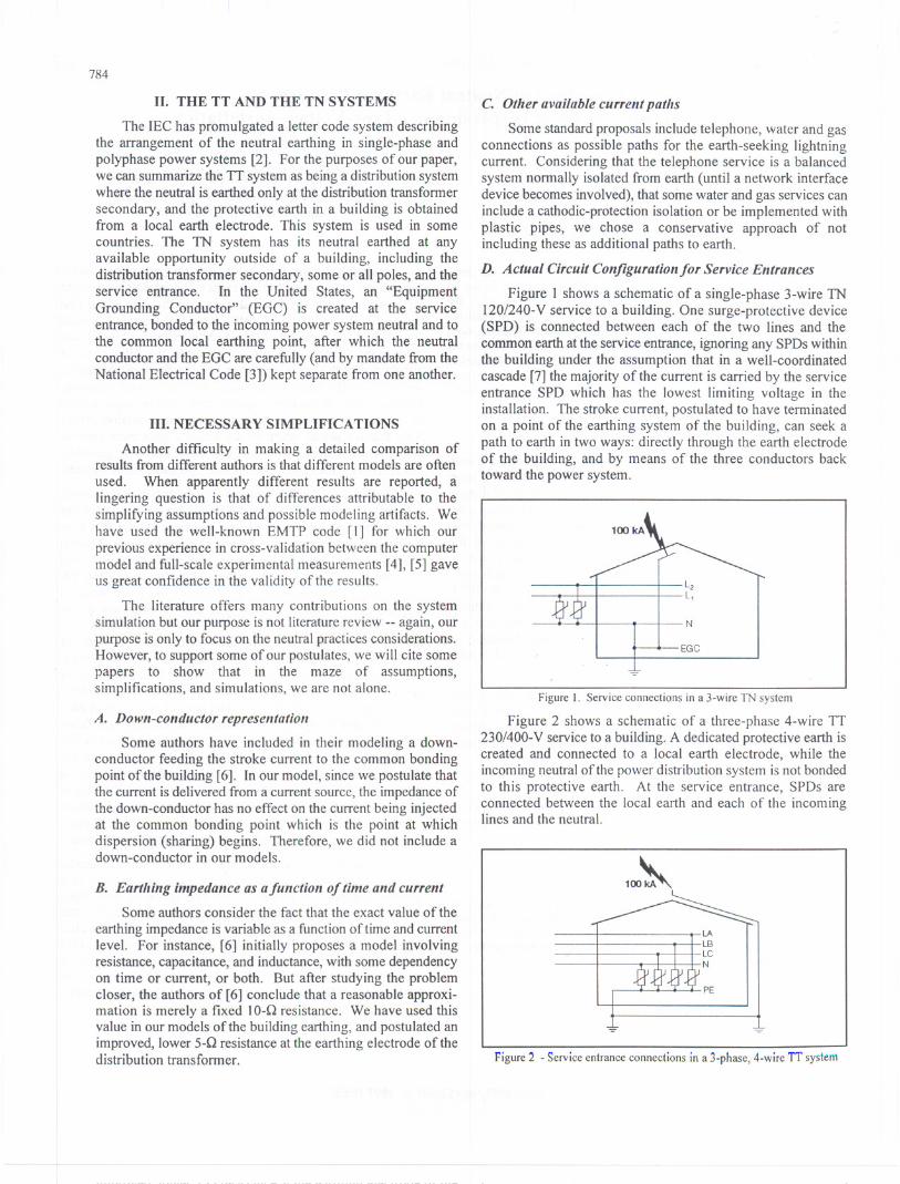
For each scenario, a pair of figures is given. The firsfigure of eachpair is a schematic showing the configurationanpoint of stroke, together with indications of the peak currenvalues in the circuit branches. The second figure of each paishows selected current waveforms, generally currents leavinthe house by way of the earthing electrode and the servicconductors. Note that the peaks can occur at different timeso that the sum of peak branch currents shown on the figuresKirkhoff notwithstanding, is not always exactly zero.
A. TN-Radial, strike on one of the buildings
A distribution transformer supplies three buildings inradial arrangement where all the service drops originate at thpole where the transformer is installed (Figure 3). Thiconfiguration is a typical U.S. residential configuration. Thlightning stroke is postulated to terminate on the earthinsystem of one of the three buildings. Figure 4 shows thcurrent waveforms.
Building3
£2..!!l..23kA
33kA
Building 1
23kA
40kA 21 kA
* Peak occurs verylate In event
20kA
Figure 3 -Radial TN configuration with three buildings supplied by Ol')edistribution transfonner, one building struck by a 10/350 J.ls, 100 leA surg~,showing peak values of currents shared among available paths.
786
oo 100 2IXI JOO
Time (I.lS)
400
SPD - Current into each line of service drop. through SPDs
GND - Current into local building earth electrode
Nout -Current into neutral conductor of service drop
Figure 4 -Waveforms of currents leaving Building 1, as defined in Figure 3,
for a 100 kA, \0/350 JIS surge terminating on the building earthing system
B. TN-Daisy chain, strike onfirst building
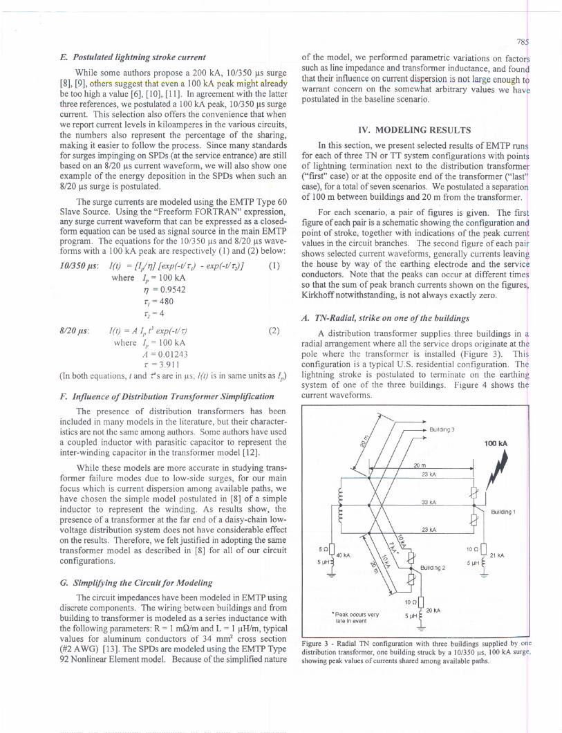
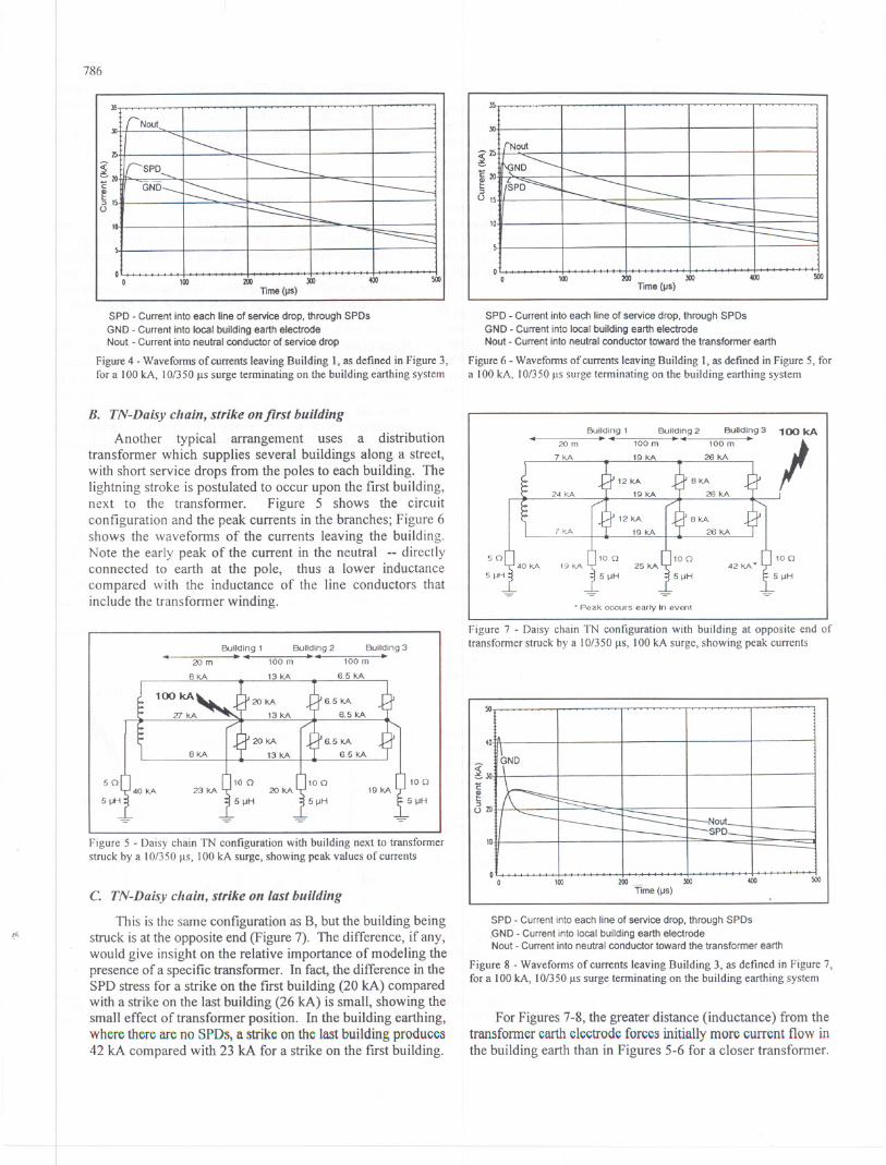
Another typical arrangement uses a distributiontransformer which supplies several buildings along a street,with short service drops from the poles to each building. Thelightning stroke is postulated to occur upon the first building,next to the transformer. Figure 5 shows the circuitconfiguration and the peak currents in the branches; Figure 6shows the waveforms of the currents leaving the building.Note the early peak of the current in the neutral --directlyconnected to earth at the pole, thus a lower inductancecompared with the inductance of the line conductors thatinclude the transformer winding.
20mBuilding 1.. Building2_4100m
Building3-100m
50 100
5j.k-i
Figure 5 -Daisy chain TN configuration with building next to transformerstruck by a 10/350 JIS, \00 kA surge, showing peak values of currents
If.
C. TN-Daisy chain, strike on last building
This is the same configurationas B, but the buildingbeingstruck is at the opposite end (Figure 7). The difference, if any,would give insight on the relative importance of modeling thepresenceof a specific transfonner. In fact, the difference in theSPD stress for a strike on the first building (20 kA) comparedwith a strike on the lastbuilding (26 kA) is small, showing thesmall effect of transfoimer position. In the building earthing,where there are no SPDst a strike on the last building produces42 kA compared with 23 kA for a strike on the first building.
15
500o
o 100 2IXI JOO
Time (IJS)
400 500
SPD -Current into each line of service drop, through SPDs
GND -Current into local building earth electrodeNout -Current into neutral conductor toward the transformer earth
Figure 6 -Waveforms of currents leaving Building I, as defined in Figure 5, fora 100 kA, 10/350 JISsurge terminating on the building earthing system
50
20mBuilding 1..
5j.k-i
.Peak occurs early In event
Figure 7 - Daisy chain TN configuration with building at opposite end oftransformer struck by a 10/350 JIS,100 kA surge, showing peak currents
50
NoutSPD
oo 100 2IXI JOO
-Time (lJs)400 500
SPD -Current into each line of service drop, through SPDs
.GND - Current into local building earth electrodeNout - Current into neutral conductor toward the transformer earth
Figure 8 -Waveforms of currents leaving Building 3, as defined in Figure 7,for a 100 kA, 10/350 JISsurge terminating on the building earthing system
For Figures 7-8, the greater distance (inductance) from thetransfonner earth electrode forces initially more current flow inthe building earth than in Figures 5-6 for a closer transformer.
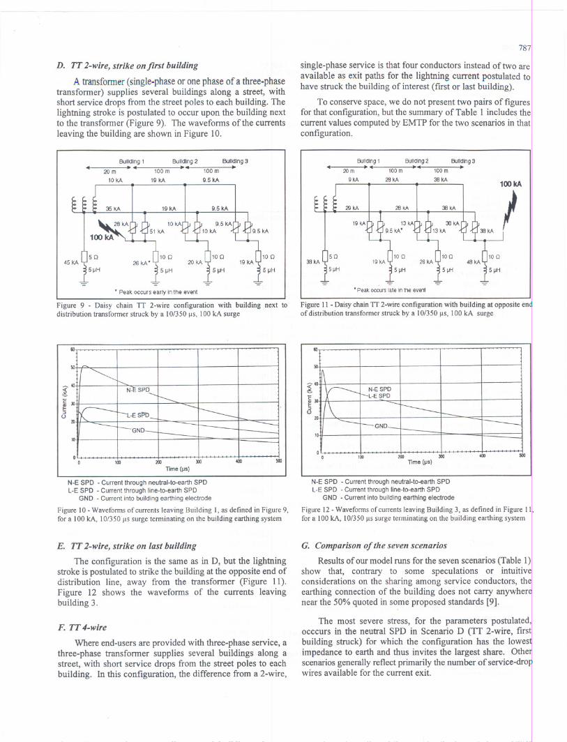
D. TT 2-wire, strike on first building
A transfonner (single-phase or one phase of a three-phasetransformer) supplies several buildings along a street, withshort service drops from the street poles to each building. Thelightning stroke is postulated to occur upon the building nextto the transformer (Figure 9). The waveforms of the currentsleaving the building are shown in Figure 10.
Building1..20m
10I<A
Building2100 m --.-...
19 I<A
Building:3100 m --+
9,5 I<A
19 I<A
5IJH
-=
* Peak occurs early In the event
Figure 9 - Daisy chain IT 2-wire configuration with building next todistribution transfonner struck by a 10/350 IlS, 100kA surge
m
GNO10
oo 100 400200 JOO
Time (liS)
N-E SPD - Current through neutral-ta-earth SPDL-E SPD - Current through line-to-earth SPD
GND - Current into building earthing electrode
Figure 10 - Wavefonns of currents leaving Building I, as defined in Figure 9,
for a 100 kA, 10/350 Ils surge tenninating on the building earthing system
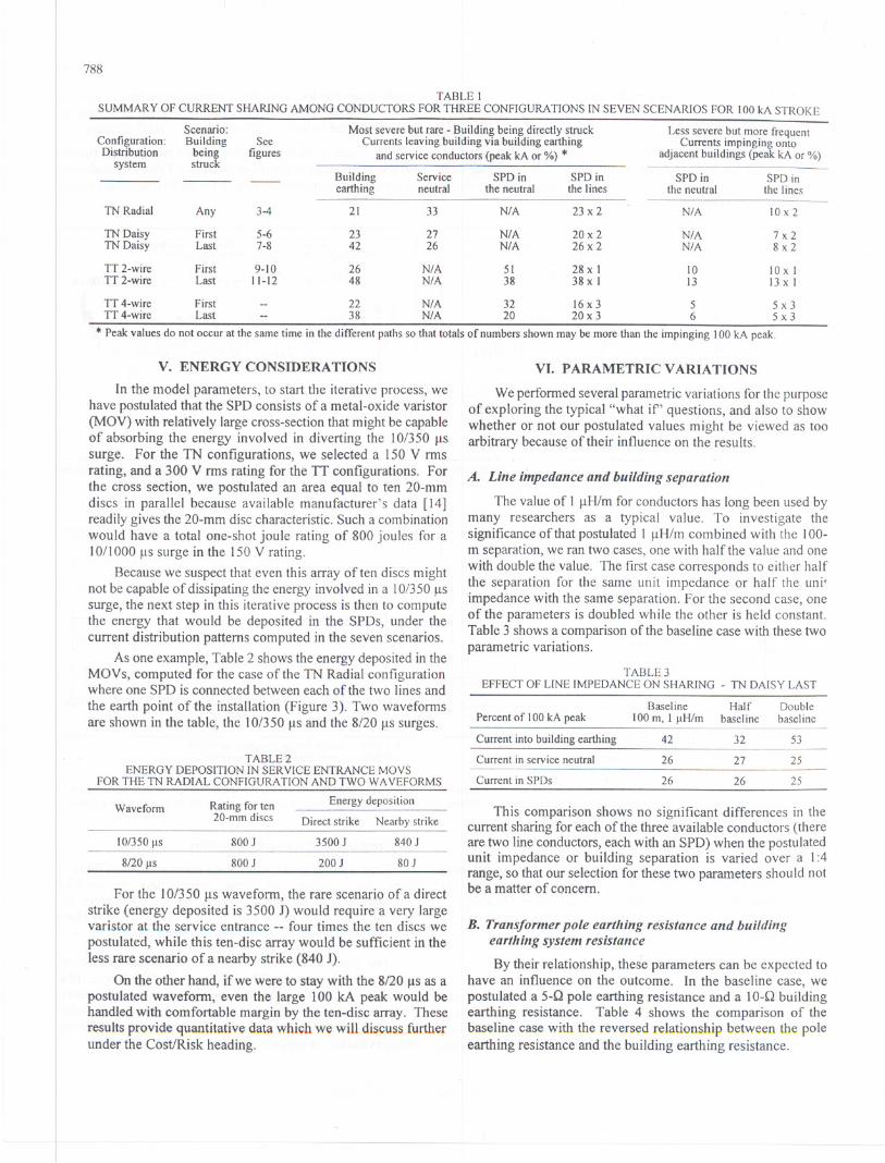
E. TT2-wire, strike on last building
The configuration is the same as in D, but the lightningstroke is postulated to strike the buildingat the opposite end ofdistribution line, away from the transformer (Figure 11).Figure 12 shows the waveforms of the currents leavingbuilding 3.
F. TT 4-wire
Where end-users are provided with three-phase service, athree-phase transformer supplies several buildings along astreet, with short service drops from the street poles to eachbuilding. In this configuration, the difference from a 2-wire,
787
single-phase service is that four conductors instead of two areavailable as exit paths for the lightning current postulated tohave struck the building of interest (first or last building).
To conserve space, we do not present two pairs of figuresfor that configuration, but the summary of Table 1 includes thecurrent values computed by EMTP for the two scenarios in thatconfiguration.
Building1--+420m
9kA
Building2
100 m ~4
28kA
Building:3100 m ---+38kA
·PeakoccurslateInthe event
Figure 11 -Daisy chain IT 2-wire configuration with building at opposite enof distribution transfonner struck by a 10/350 IlS, 100 kA surge
m
10
soo
oo 100 200 JOG
Time (liS)
coo soo
N-E SPD - Current through neutral-to-earth SPDL-ESPD - Currentthroughline-to-earthSPD .
GND - Current into building earthing electrode
Figure 12 - Wavefonns of currents leaving Building 3, as defined in Figure 11
for a 100 kA, 10/350 IlS surge terminating on the building earthing system
G. Comparison of the seven scenarios
Results of our model runs for the seven scenarios (Table 1)show that, contrary to some speculations or intuitivconsiderations on the sharing among service conductors, thearthing connection of the building does not carry anywhernear the 50% quoted in some proposed standards [9].
The most severe stress, for the parameters postulated'iocccurs in the neutral SPD in Scenario D (IT 2-wire, first
building struck) for which the configuration has the lowesimpedance to earth and thus invites the largest share. Othescenariosgenerallyreflect primarily the number of service-drowires available for the current exit.
788
TABLEISUMMARY OF CURRENT SHARING AMONG CONDUCTORS FOR THREE CONFIGURATIONS IN SEVEN SCENARIOS FOR 100 leA STROKE
V. ENERGY CONSIDERATIONS
In the model parameters, to start the iterative process, wehave postulatedthat the SPD consists of a metal-oxide varistor(MOV)with relatively largecross-sectionthat might be capableof absorbingthe energy involvedin divertingthe 10/350flssurge. For the TN configurations, we selected a 150 V rmsrating, and a 300 V rms rating for the IT configurations. Forthe cross section, we postulated an area equal to ten 20-mmdiscs in parallel because available manufacturer's data [14]readilygives the 20-mm disc characteristic.Such a combinationwould have a total one-shot joule rating of 800 joules for a10/1000 fls surge in the 150 V rating.
Becausewe suspect that even this array often discs mightnot be capable of dissipating the energy involved in a 10/350flSsurge, the next step in this iterative process is then to computethe energy that would be deposited in the SPDs, under thecurrent distribution patterns computed in the seven scenarios.
As one example,Table 2 shows the energy depositedin theMOVs, computed for the case of the TN Radial configurationwhere one SPD is connected betweeneach of the two lines andthe earth point of the installation (Figure 3). Two waveformsare shown in the table, the 10/350 fls and the 8/20 flSsurges.
TABLE2ENERGY DEPOSITION IN SERVICE ENTRANCE MOYS
FOR THE TN RADIAL CONFIGURATION AND TWO W AYEFORMS
For the 10/350 flSwaveform, the rare scenario of a directstrike (energy deposited is 3500 1) would require a very largevaristor at the service entrance -- four times the ten discs wepostulated, while this ten-disc array would be sufficient in theless rare scenario of a nearby strike (840 J).
On the other hand, if we were to stay with the 8/20 flSas apostulated waveform, even the large 100 kA peak would behandled with comfortable margin by the ten-disc array. Theseresults provide quantitative data which we will discuss furtherunder the CostJRisk heading.
VI. PARAMETRIC VARIATIONS
We performedseveral parametricvariations for the purposeof exploring the typical "what if' questions, and also to showwhether or not our postulated values might be viewed as tooarbitrary because of their influence on the results.
A. Line impedance and building separation
The value of I flH/m for conductors has long been used bymany researchers as a typical value. To investigate thesignificance of that postulated 1 flH/m combined with the lOO-m separation, we ran two cases, one with half the value and onewith double the value. The first case corresponds to either halfthe separation for the same unit impedance or half the unitimpedance with the same separation. For the second case, oneof the parameters is doubled while the other is held constant.Table 3 shows a comparison of the baseline case with these twoparametric variations.
TABLE3EFFECT OF LINE IMPEDANCE ON SHARING - TN DAISY LAST
This comparison shows no significant differences in thecurrent sharing for each of the three available conductors (thereare two line conductors,each with an SPD) when the postulatedunit impedance or building separation is varied over a 1:4range, so that our selection for these two parameters should notbe a matter of concern.
B. Transformer pole earthing resistance and buildingearthing system resistance
By their relationship, thes'eparameters can be expected tohave an influence on the outcome. In the baseline case, wepostulated a 5-Q pole earthing resistance and a 10-Q buildingearthing resistance. Table 4 shows the comparison of thebaseline case with the reversed relationship between the poleearthing resistance and the building earthing resistance.
Scenario: Most severe but rare -Building being directly struck Less severe but more frequentConfiguration: Building See Currents leaving building via building earthing Currents impinging ontoDistribution being figures and service conductors (peak leAor %) * adjacent buildings (peak leAor %)
system struckBuilding Service SPDin SPDin SPDin SPDinearthing neutral the neutral the lines the neutral the lines
TN Radial Any 3-4 21 33 N/A 23 x 2 N/A 10 x 2
TN Daisy First 5-6 23 27 N/A 20x 2 N/A 7x2TN Daisy Last 7-8 42 26 N/A 26 x 2 N/A 8x2
IT 2-wire First 9-10 26 N/A 51 28 x I 10 10 x IIT 2-wire Last 11-12 48 N/A 38 38 x I 13 13 x I
IT 4-wire First -- 22 N/A 32 16 x 3 5 5x3IT 4-wire Last -- 38 N/A 20 20 x 3 6 5x3
* Peak values do not occur at the same time in the different paths so that totals of numbers shown may be more than the impinging 100 leApeak.
Waveform Rating for ten Energy deposition20-mm discs Direct strike Nearby strike
I0/350 s 800 J 3500 J 840 J
8/20 s 800 J 200 J 80 J
Baseline Half DoublePercent of 100 leA peak 100 m, I H/m baseline baseline
Current into building earthing 42 32 53
Current in service neutral 26 27 25
Current in SPDs 26 26 25
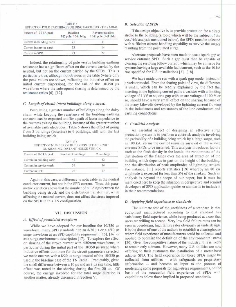
TABLE 4EFFECT OF POLE EARTHING/BUILDING EARTHING -TN RADIAL
Percentof 100kA peak Baseline Reversebaseline5-0 pole, 10-0 bldg. 10-0 pole, 5-0 bldg.
Current in building earth 21 31
Current in service earth 14
22Current in SPD
33
23
Indeed, the relationship of pole versus building earthingresistance has a significant effect on the current carried by theneutral, but not on the current carried by the SPDs. This isparticularlytrue, although not obvious in the table (where onlythe peak values are shown, reflecting the inductive effect oninitial current dispersion), for the tail of the 10/350 Jlswavefonn where the subsequent sharing is detennined by theresistance ratios [6], [12].
C. Length of circuit (more buildings along a street)
Postulating a greater number of buildings along the daisychain, while keeping the resistance of the building earthingconstant, can be expeCtedto offer a path of lesser impedance tothe currents exiting the building, because ofthe greater numberof available earth electrodes. Table 5 shows the effect of goingfrom 3 buildings (baseline) to 9 buildings, still with the lastbuilding being struck.
TABLE5EFFECT OF NUMBER OF BUILDINGS IN TN CIRCUIT
ON SHARING, DISTANT HOUSE STRUCK
Again in this case, a difference is noticeable in the neutralconductor current, but not in the SPD current. Thus, this para-metric variation shows that the number of buildings between thebuilding being struck and the distribution trans fonner, whileaffecting the neutral current, does not affect the stress imposedon the SPDs in this TN configuration.
VII. DISCUSSION
A. Effect of postulated waveform
While we have adopted for our baseline the 10/350 Jlswavefonn,many SPDstandardscite an 8/20 JlSor a 4/10 Jlssurge wavefonn as an SPD capabilityrequirement [15], [16] oras a surge environment description [17]. To explore the effecton sharing of the stroke current with different wavefonns, inparticular during the initial part of the 10/350 Jls surge whereinductive effects dominate for the circuit parameters selected,we made one run with a 8/20 JlSsurge instead of the 10/350 Jlsused in the baseline case of the TN Radial. Predictably, giventhe small difference between a 10 Jlsand an 8 JlSrise time, littleeffect was noted in the sharing during the first 20 Jls. Ofcourse, the energy involved for the total surge duration isanother matter, already discussed in Section V.
789
B. Selection of SPDs
If the design objective is to provide protection for a directstroke to the building (a topic which will be the subject of thecost/riskanalysis mentionedbelow), the SPDs must be selectedwith sufficientcurrent-handlingcapabilityto survive the surgesresulting from the postulated surge.
Alternate proposals have been made to use a spark gap asservice entrance SPD. Such a gap must then be capable ofclearing the resultingfollow current, which may be an issue forsystemshaving a largeavailable fault current, such as the 10kAnns specified for U.S. installations [3], [18].
We have made one run with a spark gap model instead ofa varistormodel. From the sharing point of view, the differenceis small, which can be readily explained by the fact thatinsertingin the lightning current paths a varistor with a limitingvoltage of I kV or so, or a gap with an arc voltage of 100 V orso, should have a very small effect on the sharing because ofthe many kilovolts developed by the lightning current flowingin the inductances and resistances of the line conductors andearthing connections.
C. Cost/Risk Analysis
An essential aspect of designing an effective surgeprotection system is to perfonn a cost/risk analysis involvingthe probabilityof a buildingbeing struck by a large surge, suchas 100 kA, versus the cost of ensuring survival of the serviceentrance SPDs to be installed. This analysis introduces factorssuch as the flash density in the locale, the randomness of thedistribution of the flashes over the area of attraction of thebuilding which depends in part on the height of the building,and the distribution of peak amplitudes of lightning strokes.For instance, [11] reports statistics [19] whereby an 80 kAamplitude is exceeded for less than 5% of the strokes. Such ananalysis is beyond the scope of our paper, but it must bementionedhere to keep the situation in perspective and reminddevelopersof SPD applicationguides or standards to include itin their recommendations.
D. Applying field experience to standards
The ultimate test of the usefulness of a standard is that!equipment manufactured according to that standard hasisatisfactory field experience, while being produced at a cost that iusers are willing to accept. Very low field failure rates can be I
seen as overdesign, high failure rates obviously as underdesign.,It is the dream of one of the authors to establish a clearinghouse I
Iwhere fieldexperience of manufacturers could be collected and.applied to optimize the definition of the environmental stressi[20]. Given the competitive nature of the industry, this is likelylto remain only a dream. However, many U.S. utilities are nowloffering to their customers the installation of a meter-base!adapter SPD. The field experience for these SPDs might belcollected from utilities --with safeguards on proprietaryIinfonnation -- and become an input to the process 0moderating some proposals for high-stress requirements, on thebasis of the successful field experience of SPDs withcapabilities below those implied in proposed standards.
Percent of 100 leA peak Baseline 3 buildings 9 buildings
Current in building earth 42 42
Current in service earth 39 14
Current in SPD 26 27
790
VIII. CONCLUSIONS
Modeling several typical TN and IT configurations ofneutral earthing practices and scenarios of lightning strike pointprovides insights on significant effects, which should lead tomore effective application of surge-protective devices (SPDs).
1. A direct lightning stroke to a building can produce highstresses on the service entrance SPDs as the earth-seekingcurrent will exit in part by way of the utility service drop.SPDs in that building will be strongly affected, while nearbybuildings will be impacted by much lower surge currents.
2. The major difference among the scenarios we have modeledappears in the current carried away trom the building by theneutral conductor.
In a TN system where the neutral is bonded to earth at theservice entrance, there is no SPD in that path, and thus noconcern about neutral SPD integrity. In typical residentialsingle-phase U.S. systems, the line SPDs can carry about25% of the stroke current.
In a IT system where there is an SPD in the neutral path,a single-phase two-wire configuration can have 50% ofthe stroke current being carried by the neutral SPD. In athree-phase IT system where there are four conductors tocarry away the stroke current, the neutral SPD can carryup to 30% of the stroke current.
3. For line conductors, the difference reflects primarily thetotal number of conductors in the system, which can be two,three or four. The earth-seeking lightning current will divide(but not always equally) among these conductors. While theinitial dispersion (during the fLrst20 Jls) is controlled by theinductances, the later dispersion is controlled by the relativevalues of the earthing resistances.
4. If the postulated stroke is as high as some of the proposedstandards suggest, modeling the behavior of service entranceSPDsof the type installedin increasingnumbersby U.S. .
utilities shows that some failures could be expected. Asfield experience seems to indicate an acceptable failure (ifany) rate, one can question the need for imposing suchsevere requirements, unless the mission of the facility issuch that even a rare failure would be unacceptable.
IX. ACKNOWLEDGMENTS
Support and encouragement for this work was provided bythe parent organization of each author. Additional support wasreceived trom Delmarva Power Company, trom Pacific Gas &Electric Company, and trom PECO Energy Company. GeraldFitzPatrick and Roger Witt contributed comments on the draft.
X. REFERENCES
[I] EPRI,"Electromagnetic Transient Program (EMTP), Version 2.0; VolumeI: Main Program: Volume 2: Auxiliary Routines, EPRI Report EL-6421-L,July 1989.
[2] IEC International Standard 364-1, Electrical Instal/ations of Buildings -Part 1: Scope, Object and Fundamental Principles, 1992.
[3] NFPA 70, National Electrical Code, 1996.
[4] MartzlofI, F.D., Mansoor, A, Phipps, K.O., and Grady, W.M., "Surgingthe Upside-Down House: Measurements and Modeling Results,"Proceedings, EPRI PQA '95 Conference, 1995.
[5] Mansoor, A and Martzloff, F.D., "Driving High Surge Currents intoLong Cables: More Begets Less," Paper 96 SM399-6 PWRD, IEEE PESSummer Meeting, Denver CO, 1996.
[6] Rakotomalala, A, Auriol, Ph., and Rousseau, A, "Lightning DistributionThrough Earthing System." Symposium Record, IEEE InternationalSymposium on EMC, Chicago IL, USA, August 1994, pp 419-423.
[7] Lai, 1.S. and Martzloff, F.D., "Coordinating Cascaded Surge ProtectionDevices: High-Low versus Low-High," IEEE Transactions IA-29 No.4,July/August 1993, pp 680-687.
[8] Birkl, 1., Hasse, P., and Zahlmann, P., "Systemgerechter Einsatz vonAbleitern in Niederspannungsnetzen," Elektrotechnische ZeitschriftNo.17, 1994, pp 964-971
[9] Flisowski, Z., and Mazzetti, C., "Efficiency of Lightning ProtectionSystem as Screening Measure Against LEMP," Proceedings, EMC'96ROMA, September 1996.
[10] Darveniza, M., Sargent, Limbourn, Liew, Caldwell, Currie, Holcombe,Stillman & Frowd, "Modelling for Lightning Performance Calculations"IEEE Transactions PAS-98, No.6, Nov!Dec 1979, pp 1900-1908.
[11] Kirder, E.P. and Uman, M.A, "Cloud-to-Ground Lightning Mechanismsof Damage and Methods of Protection," Seminars in Neurology, Vo1.15,No.3, September 1995.
[12] Dugan, R.C. and Smith, S.D., "Low-Voltage-Side Current-SurgePhenomena in a Single-Phase Distribution Transformer System," IEEETransactions PWRD-13, No.2, April 1988.
[13] Steigerwald, R.L., Ferraro, A., and Tompkins, R.E, "Investigation of aFamily of Power Conditioners Integrated into the Utility Grid," SandiaReport SAND81-7031, 1981, page 20.
[14] Transient Voltage Suppression Devices, Harris Corp., 1991.
[15] ANSI/IEEE C62.11-1991, IEEE Standard for Metal-Oxide SurgeArrestersfor AC Power Circuits.
[16] ANSI/IEEE C62.34-1996, IEEE Standard for Performance of Low-Voltage Surge-Protective Devices (Secondary Arresters).
[17] ANSIIIEEE C62.41-1991, IEEE Recommended Practice on SurgeVoltages in Low-Voltage AC Power Circuits.
[18] UL Std. 1449, Transient Voltage Surge Suppressors, 1996.
[19] Berger, K., Anderson, R.B., and Kroninger, H., "Parameters of LightningFlashes," Electra, 1975-80, pp 1548-1565
[20] Martzloff, F.D., "Keeping up with the Reality of Today's SurgeEnvironment," Power Quality Solutions. September 1995 Proceedings,pp 243-249.
Arshad Mansoor (M' 1995) is anElectrical Systems Engineer at the EPR!Power Electronics Applications Center(PEAC). He received his MS and Ph.D. inelectrical engineering from the University ofTexas, Austin in 1992 and 1994respectively. His areas of interest includePower Quality, power systems transientsanalysis, harmonics, surge propagation andprotection, and EMTP model development.
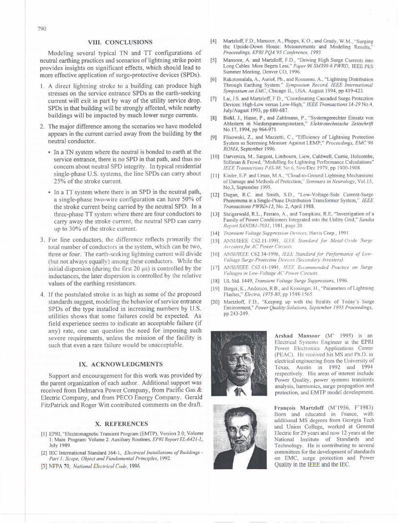
Fran~ois Martzloff (M'1956, F'1983)Born and educated in France, withadditional MS degrees from Georgia Techand Union College, worked at GeneralElectricfor29 years and now 12years at theNational Institute of Standards andTechnology. He is contributing to severalcommitteesfor the developmentof standardson EMC, surge protection and PowerQuality in the IEEE and the lEe.
Discussion
P. Hasse and J. Birkl (Dehn + Sohne, 92318 Neumarkt,Germany): The problem of lightning current distributiondepending on the different kinds of current distributionsystems and under the influence of possible variables has beenvery clearly represented with this contribution.
The curve development gained by the EMTP programmatches very well with the simulation calculations conductedin Germany with the PSPICE program.
In respect to the described results, however, a few additionsare necessary from our point of view:
1. Section III. G. and VI. A.:
The induction of a conductor system always results out ofthe geometric system of the slip-knot consisting of comingand going conductor. A separation in coming conductorimpedance and going conductor impedance is not realistic.
In particular, in case of multiple conductor cables it is to beobserved that in case of the same flow direction of thelightning current, the inductivity of the total systemdifferentiates to a single conductor system. .
2. Section VI. Schedules 3 - 5:
In particular, in case of longer connecting cables betweenbuildings and between building and transformer a changein waveform of the surge flowing through these cables.Only the observance of the amplitude factor of the flowinglightning currents is not sufficient. In this situation, itwould be more meaningful to consider also the energydistribution.
3. Section VII. B.:
For decades now, in Europe, spark gap arresters, with amains follow current quenching capability, are beinginstalled successfully as lightning current arresters at thebuilding entrance. In particular, the high down-lead abilityand impulse-time shortening of the rest impulse make afavourable co-ordination with connecting MOV's possible.
4. Section VII. 4:
The lightning protection necessity for a system, as well asthe deduced lightning protection class resulting from this,is described in IEC 1662. At the same time the lightningprotection class is determined, the layout of the lightningprotection system necessary lightning parameters aredefined (IEC 1312-1). A deviating layout of protectionmeasures on the basis of test currents 8/20 J.1sis thereforenot permissible.
Manuscript received November 3, 1997.
79
Fran~ois D. Martzloff (National Institute of Standards anTechnology, Gaithersburg MD) :
We thank the two authors of the discussion for taking the timto review our paper and provide comments aimed at broadeninthe consensus on the subject. In particular, we are delighted thear that our computations based on EMTP matches very welwith the simulationcalculationsconducted in Germany with thPSPICE program. With respect to their specific four comment"'l'we offer the following responses, preceded by the gener.remark that the purpose of our computations was to reveal thdifferences among various postulates for the circuit configurations, as influenced by the grounding practices for the neutrin effect in different countries, rather than the precise values foa particular set of parameters. We emphasize the concept 0postulate, lest we fall into the trap of taking electromagnetienvironment standards as an exact duplication of reality, whilthey are in fact only the documentationof an industryconsensuon how reality might be represented I.
1. Section II G and IV A
Indeed, the concept of inductance is based on a conductivloop that carries the current in a closed circuit. However, in thcircuits we postulated for our computations, the conductors iquestion - phase and neutral - may be considered as one pof the closed circuit and might be cal1ed"coming," accordingthe terminology used by our colleagues, while the path cosistingof the earth, the distant return to the cloud, the lightninchannel, and even the down-conductor (see Section III A) mabe considered as the other part of the loop and might be calle"going" conductors.
For this reason, we represented in our figures the phase anneutral as if they were separate, while in reality they can besome finite distance from each other (the so-called "opewiring" used in overhead lines) or in close vicinity,as in the casof an undergroundcable or an overhead "triplex." Aware of thdifferences, we startedour computations for a given, postulateconfiguration- alwaysthe same for the variationsin the neutrgrounding - but performed a parametric variation in the lininductance (taking twice or half the value used in the baseline~,as stated in the subject paragraph, to convince ourselves that thlinfluence on dispersion is not large enough to cause concer...Space limitations for the paper prevented us from providindetailed numerical results - as they also do here - andwere hoping that our simple statement that we did consider tlljeissue and found little effect on the differences among neutralgrounding scenarios might be acceptable.
2. Section VI 3 to 5
One of the results of our computationsbased on a postulat.
10/350 flS waveform was to show that, for the distances jeselected, the impedance of the cable between buildings - andthereforetheirlength- hasonlya smallinfluenceon thelon
~
-term current waveform and dispersion among conductors, whi h
is primarily influenced by the postulated values for respecti eearthing resistances. With the values selected for inductance...,
792
the current dispersion is substantially affected by the respectiveinductances only for the first 20 or 30 flS.
We agree that additional infonnation might be conveyed byreporting the energy distribution along the complex path of thelightning current, but here again space limitations intervene. Wecan offer the response, however, that in view of the large valuesof the earthing resistance compared to the other resistances inthe circuit - cable resistances and dynamic "resistances" of thevaristor or gap SPDs - the latter are not a priority in reportingresults. The EMTP model of course has the capability ofreporting any set of parameters if "asked" to do so.
For specific applications of one type or another of SPDtechnology, the EMTP model can provide detailed informationon the energy that will be deposited in these SPDs for thevarious scenarios to be considered.
Section VII B
We are aware that in some countries, the installation of a
service-entrance arrester is a common practice, and that gappedarresters may be used for that purpose. The issue is one of costvs. benefits for an arrester designed for the large lightningcurrents associated with a rare direct strike to the building. Wehave observed, during our interactions with several internationalor IEEE technical committees, that consensus has not been
reached on what current wavefonn and peak amplitudes shouldbe considered when making the cost vs. benefits analysis.Depending on the nature of the installation, the cost vs. benefitsequations are different. Several proposals for "risk analysis" arecurrently under consideration in several standards-developingbodies, and consensus is clearly not achieved at this point. Thislingering question is addressed in our response to the fourth andlast comment after the present one.
Our intention in making the remark on available faultcurrent in the second paragraph of this section was not to contestthe successful European experience cited by our colleagues, butto alert our readers at large to the importance of considering thatrequirement. The point that mains follow-current quenchingcapability is not trivial was con finned in a comment by one ofthe reviewers of our forthcoming paper, "Gapped Arresters
Revisited" (scheduled for presentation at the IEEE-PES Winter1998 Meeting and later publication in IEEE Transactions).
Section VII 4
We are aware of the work conducted in the IEC TechnicalCommittee 81, the responsible body for developmentof the IEC61662 and IEC 61312 publications. We are also aware of somediscomfort among other parties concerning the stipulations fromthat body which might result in less than fully cost-effectivesolutions to the question of real necessity for protection againstworst-case scenarios. The footnote offered in support of ourintroductory remark applies here also. There is a long andsuccessful history of application of surge-protective devicesbased on a postulated 8/20 flSsurge current wavefonn, using theappropriate values of amplitudes. For that reason, we includedin our paper as alternatepostulate the 8/20 fls wavefonn. Fromthe point of view of IEC TC 81, their recommendationsmightbeconsidered nonnative and thus non-negotiable, but protectionmeasures in the various countries are typically determined - ifat all - by bodies that promulgate codes based on a consensusdrawn from experience based not exclusively on TC 81 recom-mendations. Therefore, the use of the tenn "not permissible"appears somewhat strong in the context of voluntary or evenregulatory practices.
In conclusion, we appreciatethe opportunityto presentmoredetailed background infonnation on our computations andunderlying postulates, thanks to the discussion contributed byour colleagues.
1. Long ago, my mentor, Frank Fisher, taught me this conceptwhich I recite in thefollowing terms, well worth repeatingin thepresent context: "The criterion of validity of an environmentstandard is not so much how closely it duplicates reality butrather how well equipment designed in accordance with thisstandard perform in the field. If equipment designed inaccordance with the standard perform well in the field, whileequipment ignoring the standard do not perform well, thechances that the standard be a good standard are pretty good. "
Manuscript received January 7, 1998.