the effect of beam depth on the seismic behavior of flange ... · connection in the test specimens...
TRANSCRIPT

The Effect of Beam Depth on the Seismic Behavior of
Flange
Flange Plate Connections Between Steel Beam and Box
Column
A. Deylami, M. Tehranizadeh & M. Gholami Amirkabir University of Technology, Iran
SUMMURY
This paper presents analytical and experimental studies on the cyclic behavior of flange plate
connection between a steel beam and a welded box column. Two full-scale specimens were tested to
evaluate the effect of beam depth on the seismic response of flange plate connection. The flange plate
connection in the test specimens achieved the AISC seismic provision requirements for special
moment frames. The test results indicate that a deeper beam can lead to a greater potential for fracture
in the groove weld joining the beam web to the beam flange at the plastic hinge region. Then, the
finite-element model developed using ABAQUS was validated using the test results. The validated
finite element model was subsequently used to further investigate the behavior of the test specimens.
keywords: Connections; Flange Plate; Box Columns; Steel beam; Experimental program; Finite element
analysis; beam depth
1. INTRODUCTION
Box columns are frequently employed in areas of high seismic risk because they have an excellent
capacity to resist biaxial bending. Cold-formed hollow sections are often used for low and medium
rise buildings and built-up sections made up of four plates welded together are used for high rise
buildings (Nakashima et al, 2000). Extensive studies have been carried out and several new
connection details have been proposed for the connection of I-beams to wide flange columns since the
1994 Northridge earthquake (Kim et al, 2002, Ricles et al, 2002, Chen et al, 2005, Tabar et al, 2004,
Shiravand et al, 2010, Adeli et al, 2011). But limited research for the connection of I-beams to box–
columns has been conducted (Chen et al, 2004). Kim et al. (2004) tested two full-scale moment
connections to US box columns fabricated using pre-Northridge connection details. Test results
revealed that both specimens failed by brittle fracture of complete joint penetration (CJP) welds
between the beam flange and the column during a story drift angle of less than 1% rad, which resulted
in no plastic rotation in the connections. Chen et al (2004) tested six large scale specimens of steel
beam-to-box column connections. One of the test specimens was the unreinforced connection using
pre-Northridge details, and other test specimens were the reinforced connections using rib plates or
wing plates. The unreinforced connection was failed by fracture in the heat affected zone (HAZ) of
the beam bottom flange during 2.3% story drift angel cycle.
In the present study the behavior of a moment resisting connection, shown in Fig. 1, has been
investigated. This type of connection is mainly fabricated on site. The geometry of these plates is
considered in a manner that site welding in a horizontal position is possible for connecting flange
plates to beam and column.

Figure 1. Field welded moment connection.
In this study, two full-scale specimens with welded flange plate connection were tested to evaluate the
effect of beam depth on the seismic response of flange plate connections. The results of the
specimen’s hysteretic behavior were obtained and compared to the AISC seismic provision
requirements in order to qualify the flange plate connections.
2. EXPRIMENTAL PROGRAM
The behavior of the moment connections under severe cyclic loading, particularly in regard to the
initiation and propagation of fracture, cannot be reliably predicted by analytical means alone.
Consequently, the satisfactory performance of connections must be confirmed by laboratory testing.
Therefore, an experiment was carried out to clarify the seismic behavior of the flange plate
connections. The testing procedure and test results for global and local seismic behavior of the test
specimens are presented in the following sections.
2.1. Test specimens
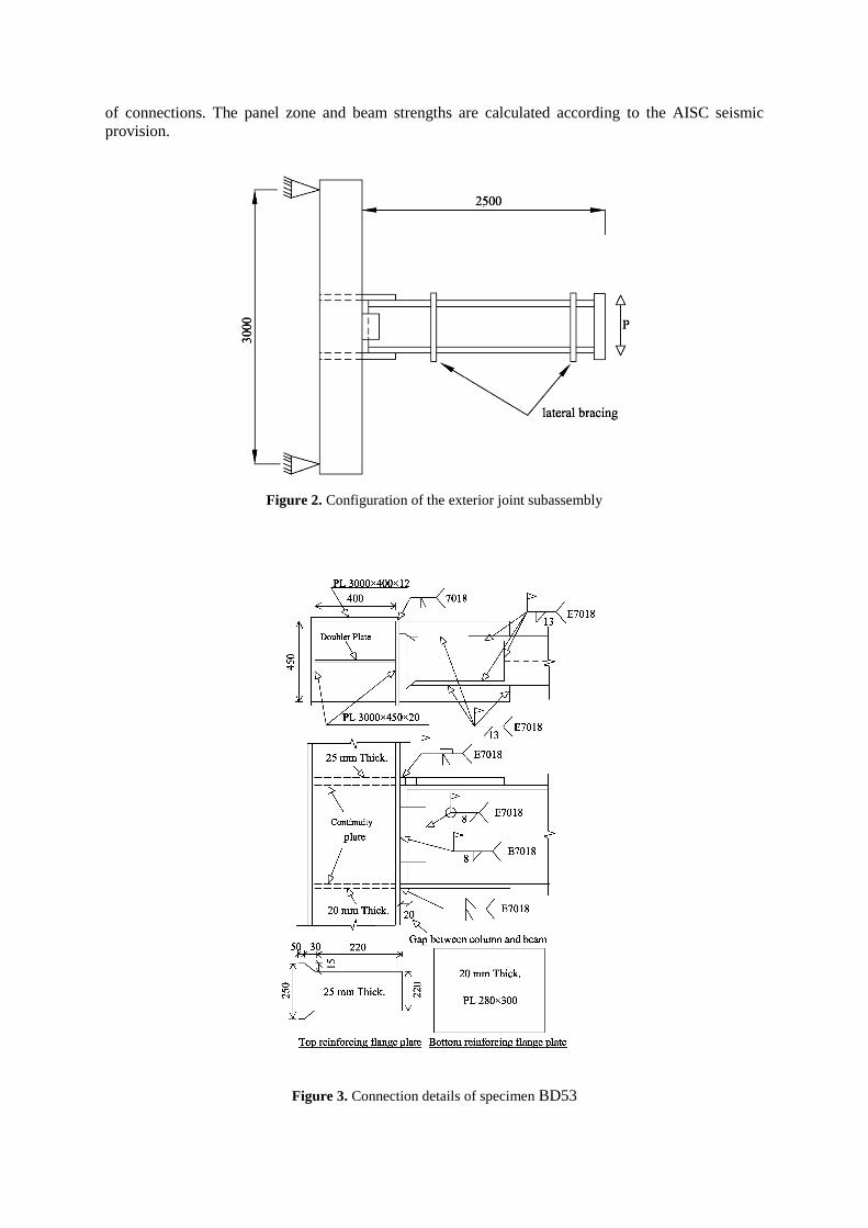
Two large-scale specimens were designed to simulate an exterior T-shaped joint subassembly. Each
subassembly contained a column between the mid-height of the two adjacent floors and a half-span of
the beam. The general configuration of the subassembly is shown in Fig. 2. To consider the practical
aspects, the size of the beam and the column sections in specimens was selected from exterior
connections of a 20 stories building. The building was designed according to AISC 360-05 and AISC
341-05 provisions.
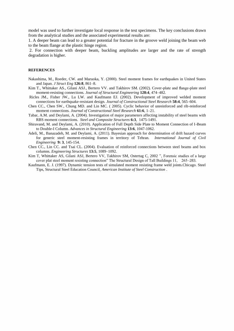
Summary information on the specimens is presented in Table 2.1. Fig. 3 shows connection details of
specimen BD53. Beam geometry of specimen BD53 was identical to that of BD33 except that the
beam depth was increased from 330 to 530 mm. Note that a doubler plate was added to the panel zone
of specimen BD53 to ensure that all specimens have approximately the same panel zone strength to
beam strength ratio. This is especially important since panel zone rotation can affect on the response
of connections. The panel zone and beam strengths are calculated according to the AISC seismic
provision.
Figure 2. Configuration of the exterior joint subassembly
Figure 3. Connection details of specimen BD53

Table 2.1. Summary Information on specimens
specimen Beam size
Column size Beam
length
doubler plate Panel zone strength
to beam strength ratio
BD53
BD33
H-530×250×10×15
H-330×250×10×15
B-450 × 400 × 20 × 12
B-350 × 400 × 20 × 20
2500
2500
15
--------
1.1
1.1
Note: All dimensions in mm.
2.2. Test setup and instrumentation
According to the shape of the specimens, a test setup was prepared to simulate the boundary
conditions of the exterior joint subassembly in a laterally loaded moment frame. The column top and
bottom were supported by real hinges. The beam was laterally braced in the vicinity of the plastic
hinge and also near the beam end. The general configuration of the test setup is shown in Fig. 4. The
cyclic displacement proposed by AISC seismic provisions was applied at the tip of the beam by a
hydraulic actuator.
Figure 4. Test setup configuration
2.3. Test observations
Figs. 5 and 6 show the test specimens BD33 and BD53 at the end of the test, respectively. In the both
test specimens, plastic hinge forms in the beam at the nose of flange plates. Such a result is desirable
Pin
Box C
olu
mn
Actu
ato
r
Beam
Lateral
Supports
Pin

because the objective of the flange-plate connection is to force inelastic action in the beam away
from the column face.
In the specimen BD53, tearing was occurred in the groove weld joining the beam web to the beam
flange at the plastic hinge region, as shown in Fig. 6. In contrast, no crack was observed in the
specimen BD33. This result indicates that a deeper beam can lead to a greater potential for fracture in
the groove weld joining the beam web to the beam flange at the plastic hinge region. There is a
possible explanation for this result:
A deeper beam results in a higher plastic strain in the groove weld joining the beam web to the beam
flange at the plastic hinge region due to an increase in the amplitude of beam flange local buckling.
The higher plastic strain increases potential for fracture .
Figure 5. Specimen BD33 at the end of the test.
Figure 6. Fracture at the groove weld joining the beam web to the beam flange in the BD53

2.4. General evaluation of the connection behavior
The hysteretic curves of the moment at the column face versus story drift angle (θ) for test specimens
BD33 and BD53 are presented in Fig. 7. The story drift angle is computed by dividing the total beam
tip displacement by the distance from the beam tip to the column centerline. In the test specimens,
moment resistance at 4% total story drift was more than 80% plastic moment of beam. Therefore,
flange plate connection in the specimens achieved the AISC seismic provision requirements for
special moment frames. It should be noted that the strength degradation of the specimens resulted
from beam flange and web buckling during the cyclic loading.
In specimen BD53, the peak moment resistance is reached at 2% rad story drift, followed by a fairly
rapid deterioration in strength with increasing drift due to flange and web local buckling. In contrast,
peak resistance in specimens BD33 is reached at 4% rad and the rate of post peak connection strength
degradation is markedly slower. The rate of strength degradation of the moment resistance in
connections is related to the amplitude of beam flange local buckling. For connection with deeper
beam, buckling amplitudes are larger and the rate of strength degradation is higher.
a)
b)
Figure 7. The hysteretic curves for test specimens a) BD33 and b) BD53

3. NONLINEAR FINITE ELEMENT ANALYSIS
Finite-element analysis can provide considerable insight into behavior of test specimens.
3.1. Finite element modeling
ABAQUS models of BD53 and BD33 were prepared. As shown in Fig. 8, groove welds and fillet
welds were modeled. The beam, column, plates, CJP groove welds and fillet welds in the model were
discretized using three-dimensional solid (brick) elements. The size of the finite-element mesh varied
over the length and height of the model. A fine- mesh was used near the connection of the beam to the
column and the beam flange to the reinforcing plate. A coarser mesh was used elsewhere. Most of the
solid elements were right-angle prisms. Hinged boundary conditions were used to support the column
top and bottom. The load was applied by imposing incremental vertical displacements at the beam tip
during the analysis.
Data from tests of coupons extracted from the beam and column of specimen were used to establish
the stress-strain relationships for the beam and column elements. The weld material was modeled
using the test data of Kaufmann (1976). Table 3.1 presents the material properties used for the
analytical models. A bilinear stress-strain relationship was assumed for each of the components
identified in Table 3.1. The Poisson’s ratio was taken as 0.3 for all materials throughout the analyses.
To account for material nonlinearities, the von mises yield criterion was employed.
Figure 8. Finite element model
Table 3.1. Material properties used for the analytical models
Yield point Ultimate point
Component Stress (Mpa)
Strain (%)
Stress (Mpa)
Strain (%)
Beam flange 3050 0.15 4200 18
Beam web 2900 0.145 4100 18
Column flange 2700 0.135 3650 15
Column web 2700 0.125 3650 14
Reinforcing plates 2650 0.1225 3600 15
Continuity plates 2650 0.1275 3700 15
Weld material 5250 0.26 5600 12
3.2. Model validation
The finite element analysis of models BD53 and BD33 were performed. The cyclic outcomes are
compared with the cyclic experimental results. As shown in Fig. 9 the experimental and finite element
results of BD53 are in good agreement. While the ultimate load and initial stiffness are well
evaluated, the extant differences between the two data sets are justified by geometric differences

between the finite element models and specimens, uncertainties in the material model, and also
unavoidable residual stresses.
b)
Figure 9. Combined plot of experimental and analytical results for specimen BD53
3.3. PEEQ distribution in the specimens
The validated models were used to evaluate the PEEQ distribution in the test specimens. Fig. 10
presents the PEEQ contours in the finite element models BD53 and BD33. The key observations from
Fig. 10 are 1) finite element models exhibited behavior as observed in the test specimens in the way of
forming plastic hinge in the beam at the nose of flange plates, 2) The maximum PEEQ value of BD53
is substantially larger than that of BD33. This result indicates that a deeper beam results in a higher
plastic strain at the plastic hinge region.
Fig. 11 presents the PEEQ contours in the groove weld joining the beam web to the beam flange at the
plastic hinge region for models BD53 and BD33. The maximum PEEQ value of BD53 is substantially
larger than that of BD33. For this reason, the tearing was occurred in the groove weld at the plastic
hinge region of specimen BD53 (as shown in Fig. 6).
a)

b)
Figure 10. Equivalent plastic strain distribution in the finite element models a) BD33, b) BD53
a)
b)
Figure. 11. Equivalent plastic strain distribution in the groove weld joining the beam web to the beam flange at
the plastic hinge region for models a) BD33, b) BD53
4. CONCLUSIONS
Two full-scale specimens with flange plate connections were tested to evaluate the effect of beam
depth on the seismic response of connection. Flange plate connection in the test specimens achieved
the AISC seismic provision requirements for special moment frames. Then, a validated finite element
model was used to further investigate local response in the test specimens. The key conclusions drawn
from the analytical studies and the associated experimental results are:
1. A deeper beam can lead to a greater potential for fracture in the groove weld joining the beam web
to the beam flange at the plastic hinge region.
2. For connection with deeper beam, buckling amplitudes are larger and the rate of strength
degradation is higher.
REFERENCES
Nakashima, M., Roeder, CW. and Maruoka, Y. (2000). Steel moment frames for earthquakes in United States
and Japan. J Struct Eng 126:8, 861–8.
Kim T., Whittaker AS., Gilani ASJ., Bertero VV. and Takhirov SM. (2002). Cover-plate and flange-plate steel
moment-resisting connections. Journal of Structural Engineering 128:4, 474–482.
Ricles JM., Fisher JW., Lu LW. and Kaufmann EJ. (2002). Development of improved welded moment
connections for earthquake-resistant design. Journal of Constructional Steel Research 58:4, 565–604.
Chen CC., Chen SW., Chung MD. and Lin MC. ( 2005). Cyclic behavior of unreinforced and rib-reinforced
moment connections. Journal of Constructional Steel Research 61:6, 1–21.
Tabar, A.M. and Deylami, A. (2004). Investigation of major parameters affecting instability of steel beams with
RBS moment connections. Steel and Composite Structures 6:3, 1475-1491.
Shiravand, M. and Deylami, A. (2010). Application of Full Depth Side Plate to Moment Connection of I-Beam
to Double-I Column. Advances in Structural Engineering 13:6, 1047-1062.
Adeli, M., Banazadeh, M. and Deylami, A. (2011). Bayesian approach for determination of drift hazard curves
for generic steel moment-resisting frames in territory of Tehran. International Journal of Civil
Engineering 9: 3, 145-154.
Chen CC., Lin CC. and Tsai CL. (2004). Evaluation of reinforced connections between steel beams and box
columns. Engineering Structures 13:5, 1089–1092.
Kim T, Whittaker AS, Gilani ASJ, Bertero VV, Takhirov SM, Ostertag C, 2002 ”, Forensic studies of a large
cover plat steel moment resisting connection” The Structural Design of Tall Buildings 11, 265–283.
Kaufmann, E. J. (1997). Dynamic tension tests of simulated moment resisting frame weld joints.Chicago. Steel
Tips, Structural Steel Education Council, American Institute of Steel Construction .