case study on the impact of horizontal boundary elements ...bruneau/asce 2012 purba and...
TRANSCRIPT
Case Study
Case Study on the Impact of Horizontal BoundaryElements Design on Seismic Behavior of Steel
Plate Shear WallsRonny Purba, S.M.ASCE1; and Michel Bruneau, F.ASCE2
Abstract: Acase studywas conducted to investigate the seismic behavior of steel plate shear walls having boundary elements designed by twodifferent philosophies. The first design approach does not guarantee that formation of in-span plastic hinges on horizontal boundary elements(HBEs) will be prevented, whereas the second approach guarantees that plastic hinges can only occur at the ends of HBEs. Pushover andnonlinear time-history analyses were conducted to investigate behavior. Results show that the development of in-span plastic hinges has sig-nificant consequences on the behavior of the structure through inducing (1) significant accumulation of plastic incremental deformations on theHBEs; (2) partial yielding of the infill plates; (3) lower global plastic strength compared with values predicted by code equations; and (4) total(elastic and plastic) HBE rotations greater than 0.03 radians after the structure was pushed cyclically up to a maximum lateral drift of 3%.Nonlinear time-history analyses also demonstrated that increasing the severity of the ground excitations [i.e., from design basis earthquake(DBE) to maximum considered earthquake (MCE)] acting on the structure with in-span plastic hinge accentuated the accumulation of plasticincremental deformations on the HBEs. DOI: 10.1061/(ASCE)ST.1943-541X.0000490. © 2012 American Society of Civil Engineers.
CE Database subject headings: Plastic hinges; Seismic effects; Steel plates; Shear walls; Deformation; Case studies.
Author keywords: In-span plastic hinge; Seismic behavior; Steel plate shear walls; Boundary elements design; Cumulative plasticincremental deformation.
Introduction
Numerous experimental and analytical studies have investigatedthe behavior of unstiffened steel plate shear walls (SPSW) in thepast thirty years. An AISC design guide summarizes the research(Sabelli and Bruneau 2007) that has addressed the designing andmodeling of SPSW web plates, general SPSW analysis methods,validation of satisfactory cyclic inelastic and seismic performances,and analytical procedures to calculate demands in the horizontaland vertical boundary elements (HBEs and VBEs) of the SPSW(e.g., Thorburn et al. 1983; Timler and Kulak 1983; Caccese et al.1993; Driver et al. 1997; Berman and Bruneau 2003, 2008; Qu et al.2008, to name a few). As a result of this research, provisions forSPSW design have been adopted (e.g., AISC 2005), and they havebeen increasingly implemented in seismic regions.The seismic behavior of SPSWhas traditionally benefited from the
overstrength introduced in theHBEs andVBEsof the boundary frameby capacity design principle requirements followed in previous re-search, but as practicing engineers are becoming more familiar withthis structural system, they are finding ways to optimize the systemand eliminate much of that overstrength to achieve smaller boundaryelement member sizes (Qu and Bruneau 2009). This can becomeproblematic in light of the challenges that sometimes exist in deter-
mining satisfactory demands in designing the HBEs (e.g., Lopez-Garcia and Bruneau 2006; Qu et al. 2008; Vian and Bruneau 2005).The 2005 AISC Seismic Provisions for Structural Steel Build-
ings (AISC 2005) requires that HBEs and VBEs be designed toremain essentially elastic under the maximum tension forces fromthe yielded infill plates, with the exception of plastic hinging atthe ends of HBEs. However, the provisions do not specify ananalysis procedure to guarantee that this intent is met (although thecommentary provides some guidance that could be used for thispurpose). As a result, at least two different common design ap-proaches have been encountered in practice for which SPSWsare likely to develop in-span hinges. In a first approach, structuralengineers typically use the results of an elastic analysis programand verify that the moments do not exceed the plastic momentcapacity of the HBE. That by itself does not protect against in-spanhinges. In the second approach, compounding on the first one,structural engineers seek to optimize the distribution of resistanceto the lateral load between the boundary elements and infill plate,such as obtaining a boundary frame with the strength to resist itsshare of the lateral loads equal to that required to resist the demandsfrom capacity design principles (i.e., attributable to the yieldingplates), effectively eliminating the overstrength of the boundaryframe (e.g., Qu and Bruneau 2009). In both cases, structural engi-neers might not anticipate that their design may lead to in-spanHBE plastic hinges (unless these analyses are complemented bythe use of nonlinear analysis programs to predict the plastic mecha-nism of structures). In parallel, some structural engineers fullyrecognize the potential for in-span hinging to develop but questionthe merit of limiting the location of plastic hinges to only occurat the ends of HBEs because, in general, this design requirementresults in a relatively substantial size of boundary elements. Thus,to achieve more economical designs, structural engineers are at-tempting to minimize overstrength by allowing plastic hinges
1Graduate Research Assistant, Dept. of CSEE, Univ. at Buffalo,Amherst, NY 14260 (corresponding author). E-mail: [email protected]
2Professor, Dept. of CSEE, Univ. at Buffalo, Amherst, NY 14260.E-mail: [email protected]. This manuscript was submitted on February 26, 2011; approved
on August 11, 2011; published online on August 13, 2011. Discussionperiod open until October 1, 2012; separate discussions must be submittedfor individual papers. This paper is part of the Journal of Structural En-gineering, Vol. 138, No. 5, May 1, 2012. ©ASCE, ISSN 0733-9445/2012/5-645–657/$25.00.
JOURNAL OF STRUCTURAL ENGINEERING © ASCE / MAY 2012 / 645

to occur along the HBE span, as this leads to relatively smallerboundary elements. Whether this is acceptable has been a conten-tious issue, particularly in the absence of factual data.To investigate this concern, one must first determine whether
in-span HBE hinging, when it occurs, can affect in any way theseismic performance of SPSWs, irrespective of whether it developsintentionally in a SPSW or as a result of unintended design con-sequences. This paper presents an investigation of the questionusing a case study for this purpose. Undoubtedly, subsequent re-search and parametric studies would be useful to identify the spe-cific conditions and wall geometries (e.g., aspect ratios, numberof stories) for which specific behaviors would be obtained to quan-tify their likelihood of occurrence and to determine whether otherattenuating factors can be relied on to counter potential undesirablebehaviors. However, an understanding of the possible consequen-ces of in-span HBE plastic hinging is a prerequisite for any suchfurther questioning. In that perspective, whereas overstrength inSPSWs is recognized to arise from a number of sources duringdesign, the case study presented has been careful to ensure thatits conclusions are not biased by accidental sources of overstrengththat may or may not be present from case to case. Future analysiswould allow quantification and assessment of the reliability ofvarious sources of uncontrolled overstrength.Hence, to answer the fundamental question in this debate, this
paper presents the results of a case study that analytically investi-gated the seismic behavior of two steel plate shear walls havingHBEs designed with different plastic mechanisms. In the firstSPSW, one of the preceding design approaches is used and forma-tion of in-span plastic hinges on HBEs is possible, whereas in thesecond SPSW, plastic hinges can only occur at the ends of HBEs.Results and observations from monotonic and cyclic pushoveranalyses and time-history analyses are used to assess the relativeperformance of the two SPSWs.
Structure Description and Design of Three-StorySPSW
As a case study to investigate the possible significance of in-spanHBE plastic hinges, a three-story single-bay SPSW was selected.Bay width and typical story height were arbitrarily chosen equalto 20 and 10 ft, respectively, resulting in an infill plate aspect ratioof 2.0. Note that SPSWs having such an aspect ratio are commonnowadays (e.g., AISC 2007, 2008) and that larger values are an-ticipated as the 2010 edition of the AISC seismic provisions (AISC2010) has eliminated the previously prescribed upper limit forthat ratio. It was also assumed that the structure is located on ClassD soil in downtown San Francisco, California, and designed for anoffice building. This SPSWwas assumed to carry a tributary weightWt of 1085 kips, which corresponds to one-sixth of the total weightof the structure, distributed as 352 kips on the first two stories and381 kips on the roof. Different approaches were possible to ensurethat the strength of the chosen web plates closely matched thedesign demands (to avoid having infill plate overstrength biasthe findings of this study). For example, (1) the SPSW’s tributarymass could have been modified to match the strength of availablehot rolled plates, (2) regular perforation layouts in compliance withthe AISC 341-10 requirements for Special Perforated Steel PlateWalls (AISC 2010) could have been detailed, or (3) cold rolled steelplates could have been used. Given that all of these approacheswould lead to the same end results, for expediency the laterapproach was taken, knowing that satisfactory ductile behavior ofSPSWs having such infill plates can be obtained (Berman andBruneau 2005). Thus, light-gauge steel (Fy ¼ 30 ksi) was used
for the infill plates. ASTM A572 Gr. 50 (Fy ¼ 50 ksi) steel wasselected for the VBEs and HBEs.On the basis of the spectral acceleration maps in FEMA Report
No. 450 (2003) provisions, the design short and 1-second spectralordinates, SDS and SD1, for the aforementioned site are 1.14 g and0.85 g, respectively. The fundamental period of the structure T wasestimated using the FEMA Report No. 450 (2003) procedures as0.26 s, and using a response modification factor R of 7 andan importance factor I of 1, the total base shear V resisted by thestructure was 176 kips, distributed as lateral loads along the heightof the building of 92, 56, and 28 kips from the third to the first floor.The required infill plate thicknesses to resist those story shearforces per Eq. 17-(1) of the AISC 2005 Seismic Provisions were0.072, 0.059, and 0.036 in. for the first to the third floor, respec-tively. Those exact thicknesses were assumed to be available(slightly thicker plates would have imparted greater demands onthe HBEs but would not have significantly changed the observedbehavior described in subsequent sections). Two design procedureswere applied to design the boundary elements.
Indirect Capacity Design Approach
According to the indirect capacity design approach, described inthe commentary to the AISC seismic provisions (AISC 2005,2010), loads in the boundary elements can be determined fromthe gravity loads combined with equivalent seismic loads increasedby the amplification factor
Bi ¼Vei
Vuið1Þ
where Vei = expected shear strength calculated for the infill platethickness provided and Vui = lateral seismic force at floor i.Following this procedure, a linear analysis program is typicallyused to analyze the SPSW and size of the boundary elements.SAP2000 software (SAP2000 Version 11.0.8) was used to designthe VBEs and HBEs with the objective of obtaining a demand-to-capacity ratio close to 1.0 (without exceeding it) when resistingthe combination of gravity loads and earthquake loads increasedby the amplification factor Bi.
Combined Plastic and Linear Analysis (CapacityDesign)
The capacity design approach used combines the procedure pro-posed by Vian and Bruneau (2005) for HBEs and that proposedby Berman and Bruneau (2008) for VBEs. The latter procedureis also described in the commentary to the 2010 AISC seismicprovisions (AISC 2010).Vian and Bruneau (2005) proposed an equation to size anchor
beams (i.e., top and bottom HBEs) such that they can resist forcesgenerated by fully yielding infill plates without developing in-span HBE plastic hinges. The equation estimates the minimumrequired HBE plastic modulus as follows:
Zi ¼ωybiL2b4 Fyb
ð2Þ
where Lb and Fyb = HBE span and yield stress, respectively andωybi = vertical component of infill plate stress, defined as
ωybi ¼ Fyp tpi cos2α ð3Þwhere Fyp and tpi = infill plate yield stress and infill thickness,respectively, and α = tension field inclination angle. AlthoughEq. (2) was developed for anchor beams, it can also be appliedto the design of intermediate HBEs by considering the net stress
646 / JOURNAL OF STRUCTURAL ENGINEERING © ASCE / MAY 2012

resulting from the adjacent top and bottom infill plates of differentthicknesses. As for VBEs, the Berman and Bruneau (2008) proce-dures derive their design loads from the free-body diagrams of theSPSW uniform plastic sway mechanism (i.e., full web yielding andplastic hinge at HBE ends).The resulting sizes of VBEs and HBEs obtained by the two
different design procedures are compared in Fig. 1. Note thatthe selected sections might not be the lightest W-section availableand that the VBE section is again varied from floor to floor toensure that the following observations are not tainted by accidentaloverstrengths. The demand-to-capacity ratio for each element isdisplayed in parentheses under the resulting section shape in Fig. 1.For SPSW designed by the capacity approach, all HBE demand-capacity ratios exceed 0.98 except one at 0.95. For SPSW designedby the indirect capacity approach, the HBE ratios varied from 0.88to 0.99; however, this slight difference from the second SPSW casewill not violate the conclusions reached by this study, as is shownsubsequently. Moreover, the SPSWs resulting from the first andsecond design approach are denoted as SPSW-ID and SPSW-CD, respectively, where the ID and CD labels stand for “indirectdesign” and “capacity design,” respectively. Note that the resultingobservations on the behavior of SPSW-ID are equally applicable toSPSWs designed by any method for which in-span plastic hingesare not explicitly prevented.
Analytical Model Development
To investigate the behavior of both SPSW-ID and SPSW-CD, non-linear static analysis (pushover analysis) and time-history analysiswere conducted. Two analytical models were developed for thispurpose: (1) a strip model for monotonic pushover analysis and(2) a dual strip model for cyclic pushover analysis and time-historyanalyses. The second model can capture reorientation of the tensionfield direction as loading direction changes. The validity of such
strip models to accurately capture the nonlinear behavior ofSPSWs is well established (e.g., Driver et al. 1997, 1998; Elgaaly1998; Berman and Bruneau 2003, 2005; Qu and Bruneau 2008). Inthis study, 12 strips having an equal width S of 19.7 in. were pro-vided at every floor to model the infill plates of the two three-storySPSWs discussed in the previous section. In SAP2000, those stripswere modeled as series of tension-only bracing element, which hasstrength only in tension but no strength in compression (as com-monly done in such SPSW inelastic analyses) and were inclined inthe direction of the tension field α estimated per Eq. 17-(2) of theAISC 2005. For modeling expediency, a single inclination angle of42° taken as the average tension field angle of all panels in SPSW-ID was used throughout the analytical model. As for the VBEs andHBEs, they were modeled as a regular frame element. ASTM A572Gr. 50 steel and light gauge steel used for frame element andtension-only bracing element, respectively, were represented byan idealized elasto-perfectly plastic stress-strain material (i.e., nostrain hardening included, as conventionally done using simpleplastic theory).To capture the nonlinear behavior of the structure, nonlinear
hinges (plastic hinges) were also defined in the analytical models.Preliminary nonlinear static analyses demonstrated that for SPSW-ID, plastic hinges would develop at the ends of the HBEs and some-where along their span, whereas they only occurred at the HBEends for SPSW-CD. Hence, to develop a general model andexpedite the modeling process for both the monotonic and cyclicpushover analyses, plastic hinge elements were defined at thequarter-, mid-, and third-quarter span of each HBE, in additionto their ends. One might argue that introducing more plastic hingeelements along the HBE span (e.g., every one-tenth of the HBElength) would have allowed closer approximation of the exact lo-cation of the plastic hinges and thus give a more precise estimate ofthe SPSW ultimate strength. However, this additional computa-tional expense would only lead to marginal benefits, as known froma study of plastic mechanism under uniformly distributed loads
Fig. 1. VBE and HBE sizes with demand-to-capacity ratio results: (a) SPSW-ID; (b) SPSW-CD
JOURNAL OF STRUCTURAL ENGINEERING © ASCE / MAY 2012 / 647

(e.g., Bruneau et al. 1998), recognizing that the distributed tensionloads from the infill plates act as a distributed load on the HBEs. Inaddition, to capture yielding of strips, axial hinges (i.e., understoodas member-yielding under tension forces) were located at everytension strip over the entire stories. The SAP2000 axial-P hinge(configured and verified to exhibit correct hysteretic tension-onlybehavior) was chosen to define the inelastic behavior of the strips.The fiber P-M2-M3 hinge was chosen to define plastic hinges inthe VBEs and HBEs. This type of hinge automatically accounts forthe interaction between the axial loads and moments that can occurin the HBEs and VBEs (SAP2000).
Nonlinear Static Analysis (Pushover Analysis)
Monotonic Pushover Analysis
A monotonic pushover analysis was conducted for both SPSW-IDand SPSW-CD until each structure reached a 4% lateral drift, whichcorresponds to a 14.4 in. roof lateral displacement. The invertedtriangular vertical distribution presented in the FEMA ReportNo. 450 (2003) document was chosen to model the distribution oflateral loads along the height of the building. Lateral forces actingat every floor level were assumed to be transferred equally to theleft and right sides of the SPSWs.Fig. 2 shows the monotonic pushover results for both SPSW-ID
and SPSW-CD. At 4% drift, the base shears are 311 and 477 kipsfor the respective structures; for comparison, their respective theo-retical values (indicated in the figure by the dash lines) are 351 and488 kips, obtained using the plastic analysis equations for uniformplastic sway mechanism (Berman and Bruneau 2003). As shown inFig. 2 for SPSW-CD, the base shear obtained from the monotonicpushover analysis using SAP2000 and the theoretical calculationsusing the plastic analysis approach are in a good agreement. Thedifference between the two is only 2.3% at 4% drift. Severalfactors, such as fiber-hinge model properties, effect of axial forces,and actual tension field angle contributed to this small discrepancy(each of these effects is quantified in Purba and Bruneau 2010 andverified to add up to match the observed difference). However, forSPSW-ID, the theoretical base shear is 13%more than that obtainedfrom the monotonic pushover analysis. Even if the factors thataccounted for the discrepancy of results in SPSW-CD are appliedto this condition, an 11% disparity remains, which can only be
explained by comparing the plastic mechanism from the SAP2000analyses with the assumed theoretical one.Fig. 3 displays plastic hinge and strip yielding distributions
at 3% lateral drift for SPSW-ID and SPSW-CD, in which stripyielding is shown as broken lines, and where the circular markersindicate that a fully plastic condition has been reached on the HBEat each selected location. The same distributions are also observedat 4% lateral drift. As shown in Fig. 3(a), five out of 36 strips inSPSW-ID remained elastic, and four out of eight HBE ends did notdevelop plastic hinges. In contrast to the assumed uniform plasticsway mechanism described in the commentary to the AISC seismicprovisions (2010), four in-span plastic hinges have developed onthe HBEs of SPSW-ID. Hence, SPSW-ID certainly does not followthe uniform plastic sway mechanism (also known as panel mecha-nism) but rather consists of a sway and beam combined mecha-nism. The significant vertical deformations along the HBEsspans of SPSW-ID (as discussed subsequently in the “HBE VerticalDeformation” subsection) confirm development of this mechanism.For example, on the second- and top-floor HBEs, vertical deforma-tions observed at their span are 4.3 and 2.4 inches at 4% drift, re-spectively. In comparison, all strips in SPSW-CD yielded andplastic hinges occurred at each HBE end (i.e., total of eight plastichinges). Although the fiber-hinge elements were also present alongthe HBE span of SPSW-CD (at the same locations as for the SPSW-ID case), no in-span plastic hinge developed. This confirms thatSPSW-CD follows a uniform plastic sway mechanism.An equation to calculate the theoretical base shear strength of
SPSW having in-span plastic hinges considering their actual plasticmechanism is derived in Appendix I. Eq. (7) in that appendix givesa theoretical base shear of 304 kips for SPSW-ID, which agreesto within 2.2% with the aforementioned 311 kips result fromthe SAP2000 analysis as shown in Fig. 2. The plastic mechanismconsidered in Appendix I is general and could develop in SPSWshaving any number of stories.
Cyclic Pushover Analysis
To investigate whether plastic hinging along an HBE span couldlead to progressively increasing deformations in the HBEs of bothSPSW-ID and SPSW-CD and whether it may affect structural per-formance, cyclic pushover analysis was conducted. A progressivelyincreasing cyclic displacement history of up to 3% drift (in incre-ments of 0.5%) was applied to the top floor of the structure for thispurpose. In this paper, positive pushover displacement (producingFig. 2. Monotonic pushover analysis results
(a) (b)
Fig. 3. Plastic hinge and strip yielding distributions at 3 and 4% lateraldrift: (a) SPSW-ID; (b) SPSW-CD
648 / JOURNAL OF STRUCTURAL ENGINEERING © ASCE / MAY 2012

positive base shear) is assumed to be acting from left to right of thestructure.The resulting hysteretic curves of the base shear versus lateral
displacement up to 3% drift for SPSW-ID and SPSW-CD are com-pared in Fig. 4. As shown in Fig. 4, the backbone of both cyclicpushover analyses follows the monotonic curves without signifi-cant differences. The boundary frame plastic strength (in a swaymechanism) was observed to contribute approximately 30 and48% of the total plastic strength of SPSW-ID and SPSW-CD,respectively. This explains why SPSW-ID exhibits more pinchingin its hysteretic behavior than SPSW-CD.
Plastic Hinge and Strip Yielding Distributions. To observethe progression of plastification at several drifts of interest duringthe cyclic pushover analysis, three stages of plastification have beendefined: yielding condition, partial plastification condition, andfully plastic condition. The criterion used to define them is fromthe level of flexural moment (when the magnitude of axial forcedoes not exceed what could be considered a moderate level, a limitdefined as P ≤ 10%Py) or from fiber stress-strain information(when the magnitude of axial forces developed in one particularfiber-hinge becomes significant, P ≥ 10%Py). Using the secondcriterion, the yield condition corresponds with the stage for whichthe furthest fiber from the plastic neutral axis reaches the yieldstress, extending that initial condition up to the upper boundarydefined by the case for which all fibers on one flange yielded(i.e., per the first criterion, the flexural moment is between 88and 91% of its theoretical plastic moment); the fully plastic con-dition corresponds with the instance for which most of the fibersyielded only one or two fibers close to the plastic neutral axis
remaining elastic (i.e., the flexural moment is equal to or higherthan 97% of its theoretical plastic moment); and the partial plasti-fication condition corresponds with the cases between those twoconditions (i.e., for first criterion, the flexural moments is between91 and 97% of its theoretical plastic moment).Fig. 5(a) shows the plastic hinge and strip yielding distributions
on SPSW-ID. Plotted from left to right are the conditions at the endof the full cycle at 1, 2, and 3% drift, respectively. To gain a betterunderstanding of the plastic hinges formed in each direction of thepushover displacement, new markers were introduced in the figure,which are different from the one shown in Fig. 3 for monotonicpushover analysis. Symbolic hinges that are half-shaded or half-solid on the top part of the circular markers indicate that partialplastification or full plastic condition, respectively, was reachedon the HBE at the shown location when the structure undergoespositive drift excursion. When the structure undergoes an excursionin the reversed direction, those half-shaded or half-solid indicationsare shown on the bottom part of the circular markers to indicate thesame respective conditions. Consequently, full-shaded or full-solidindicate that the respective conditions occurred in both directions(i.e., positive and negative directions).Fig. 5(a) shows that the plastic hinge distribution at the end of
the 1% drift cycle is somewhat symmetric in both directions. Whenthe structure experienced þ1% lateral drift, a total of four plastichinges (one partial plastification and three fully plastic) occurred atthe HBE ends; and at the reversed excursion of �1% lateral drift, atotal of five plastic hinges (two partial plastification and three fullyplastic) occurred at the same HBE ends. In addition, three strips(the right-leaning or left-leaning strips for the positive or negativedirection, respectively) on the second and the third floor remainedelastic (shown as the solid lines close to the corner in the figure) andonly two strips on the first floor had yielded (shown as the brokenlines in the figure).As the pushover displacement increased, more strips yielded,
predominantly on the first floor, whereas only one additional stripyielded on the top floor. As previously observed in the monotonicpushover analysis, even at higher lateral drifts some strips remainedelastic (i.e., a total of nine right-leaning strips and 10 left-leaningstrips at the end of the 3% drift cycle). This phenomenon will beexplained in the next section. Moreover, for the plastic hinge dis-tribution, beyond the plastic hinges that occurred at the HBE ends,three locations of in-span plastic hinges were also observed onHBE2 (the second floor) and HBE3 (the third floor) at the endof 2% drift cycle. In addition, the yielding condition occurred alongthe span of HBE0 (on the ground floor) and HBE1 (on the firstfloor). At the end of the 3% drift cyclic, in-span plastic hingeson the HBEs occurred at four locations (one partial plastificationand three fully plastic) during the positive drift excursion and atfour locations (two for each partial plastification and fully plastic)during the negative drift excursion.Incidentally, one interesting behavior observed on the plastic
hinge distribution of SPSW-ID after the structure experienced ahigher drift (i.e., ≥ 2% drift) was evidence of three plastic hingeshaving formed in some of the HBEs. For example, this wasobserved on HBE2 when the structure underwent its positive driftexcursion during the 2% drift cycle and on each HBE in bothexcursion directions of the 3% drift cycle. This behavior seemsto contradict the results obtained for the theoretical sway and beamcombined mechanism observed under monotonic pushover analy-sis illustrated and further discussed in Appendix I, in which onlytwo plastic hinges on the HBEs were required to form the plasticmechanism; however, no contradiction exists. Purba and Bruneau(2010) comprehensively explained this phenomenon by conductinga step-by-step investigation on the free-body diagram of the
(a)
(b)
Fig. 4. Cyclic pushover analysis results: (a) SPSW-ID; (b) SPSW-CD
JOURNAL OF STRUCTURAL ENGINEERING © ASCE / MAY 2012 / 649

corresponding HBE (e.g., HBE3) during the 3% drift cycle. At thebeginning of this cycle, after the structure was pushed to the rightand to the left up to a maximum lateral drift of 2.5%, residual mo-ments were observed at both ends of HBE3 and no tension forcesremained in the strips because their elongations were less than theprevious maximum elongation. As a result, at an earlier stage ofpushover displacement during the 3% drift cycle, SPSW-ID be-haves similar to a moment-resisting frame, with plastification con-centrated at both HBE ends. However, as the strips regained tensionat a higher drift and resumed plastic energy dissipation anew, theleft end moment reduced during positive drift excursion whereasmoments at the quarter-span from the left and at the right end in-creased. Eventually, the plastic hinge that occurred at the left endduring increasing positive drifts was under elastic unloading andthus not plastic anymore. Instead, plastic hinges were located atthe quarter-span from the left and at the right end of HBE3, similarto the observation in the monotonic pushover analysis case. Thesame behavior was also observed during the negative drift excur-sion where the location of the plastic hinges mirrors that in the pos-itive drift excursion. Hence, this distinctive transition mechanismbetween the sway and the combined mechanism in SPSW-ID ex-plains the plastic hinge distribution observed on its HBEs shown inFig. 5(a). At the end of the cyclic pushover analysis, three plastichinges indeed developed on those HBEs but they did not occur atthe same time during the drift excursion. A small drop of HBE endmoment at a higher drift after the infill plates yielded actually alsooccurred in several HBEs of SPSW-CD. However, changing of the
plastic hinge distribution did not follow (i.e., the system remainedin its sway plastic mechanism), as opposed to the case of SPSW-ID.Fig. 5(b) shows the plastic hinge strip yielding distributions on
SPSW-CD. At the end of the 1% drift cycle, most of the stripsyielded; only four right-leaning strips and five left-leaning strips(i.e., close to corners) remained elastic. In contrast to SPSW-ID,for the SPSW-CD, all strips completely yielded at the end of the3% drift cycle. In addition, all plastic hinges developed at the HBEends and no in-span plastic hinge developed.
HBE Vertical Deformation. A most significant phenomenonobserved is the HBE vertical downward deformation of SPSW-ID,progressively increasing and of significant magnitude as the lateraldrift increased. This can be observed especially on the top twoHBEs, as shown in Fig. 6(a). For example, the vertical deformationon the top HBE progressively increased from 0.8 to 2.3 in. when thestructure was pushed from 1 to 3% drift. Additionally, when thestructure returned to its original position after it went through a full3% drift cycle, the residual vertical deformation of the top HBEremained significant at approximately 1.7 in. (shown in Fig. 7).This significant HBE vertical deformation prevented the cornerstrips (i.e., the top left corner on the second and the third floorfor positive pushover displacement and both strips on the top leftand bottom right corners on the first floor) to completely stretch upto the yield displacement. This further explains why in Fig. 5 thosecorner strips remained elastic and in-span hinges developed. As aconsequence of this behavior, the infill plates in SPSW-ID did notdevelop their full capacity to resist the specified lateral loads. Bycomparison, for SPSW-CD, relatively small vertical deformations
Fig. 5. Plastic hinge and strip yielding distributions on (a) SPSW-ID; (b) SPSW-CD
650 / JOURNAL OF STRUCTURAL ENGINEERING © ASCE / MAY 2012

actually occurred on the HBEs during cyclic pushover analysis.The largest HBE vertical deformation is 1.1 in. atþ3% lateral drift.However, this is not large enough to create in-span plastic hingingand becomes only 0.5 in. (shown in Fig. 7 for HBE3) when thestructure returns to its original position.The complete history of vertical displacements of HBEs as a
function of structure lateral drift, as shown in Fig. 7, is also instruc-tive to explain the performance of the HBEs designed by the twodifferent approaches. This figure compares vertical displacementhistory at the midspan of the top HBE for both SPSWs, in terms
of (1) the maximum drift of every cycle (called the backbonedisplacement) and (2) when the structure returns to its originalposition at 0% drift (called the residual displacement). Thebackbone-displacement slope of SPSW-ID is larger than that ofSPSW-CD, implying that the HBE vertical downward displacementfor SPSW-ID increases faster than that for SPSW-CD. In otherwords, this accumulative plastic incremental deformation attribut-able to cyclic pushover displacement detrimentally affects thestructural performance of SPSW-ID. For example, at þ3% drift,the HBE3 vertical displacement of SPSW-ID was 2.3 in., or ap-proximately 2.6 times larger than that of SPSW-CD, which was0.9 in. The same trend was also exhibited with the residual dis-placements. At the end of the 3% drift cycle, HBE3 residual dis-placement for the SPSW-ID was 3.5 times larger than that for theSPSW-CD. In addition, progression of the HBE residual displace-ment from one cycle to another cycle is quicker for the SPSW-IDthan that for the SPSW-CD. Moreover, this phenomenon on SPSW-ID is even worse if a smaller W-section was been used for the topHBE such that its demand-to-capacity ratio was closer to 1.0. Avalue of 0.88 (as shown in Fig. 1) was obtained for that topHBE in the SPSW-ID case compared with the corresponding0.99 value at the top HBE of SPSW-CD. If anything, this discrep-ancy reinforces the conclusions reached by this case study.
Moment-Rotation Comparison. Another approach that can beused to examine the behavior of the two SPSWs is comparing themoment-rotation hysteresis of their HBEs, as in Fig. 8, which plotsthe normalized moment-rotation hysteresis of each HBE(arranged vertically from the top to the bottom HBE) obtainedduring the cyclic pushover displacements. The normalized termsplotted are M∕Mp and θ∕θ0:03, where M and Mp = end moment
(a) (b)
Fig. 6. Schematic deformed shapes of (a) SPSW-ID; (b) SPSW-CD
Fig. 7. History of HBE3 vertical displacement (cyclic pushover)
JOURNAL OF STRUCTURAL ENGINEERING © ASCE / MAY 2012 / 651
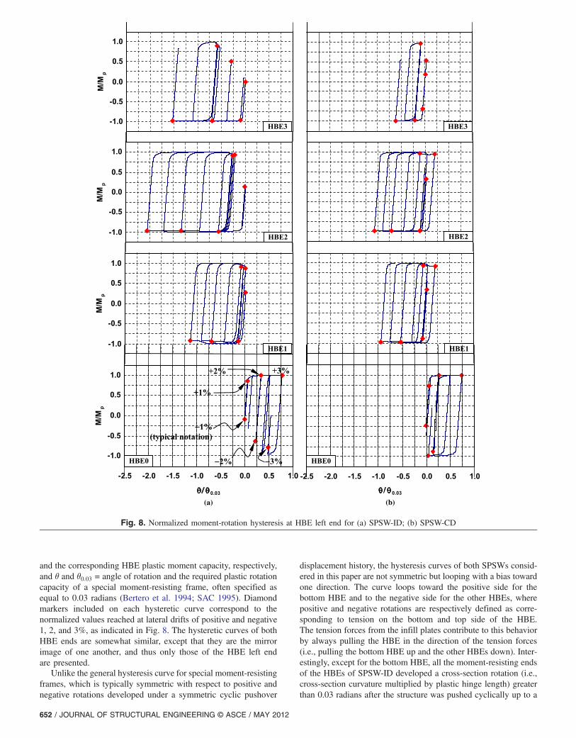
and the corresponding HBE plastic moment capacity, respectively,and θ and θ0:03 = angle of rotation and the required plastic rotationcapacity of a special moment-resisting frame, often specified asequal to 0.03 radians (Bertero et al. 1994; SAC 1995). Diamondmarkers included on each hysteretic curve correspond to thenormalized values reached at lateral drifts of positive and negative1, 2, and 3%, as indicated in Fig. 8. The hysteretic curves of bothHBE ends are somewhat similar, except that they are the mirrorimage of one another, and thus only those of the HBE left endare presented.Unlike the general hysteresis curve for special moment-resisting
frames, which is typically symmetric with respect to positive andnegative rotations developed under a symmetric cyclic pushover
displacement history, the hysteresis curves of both SPSWs consid-ered in this paper are not symmetric but looping with a bias towardone direction. The curve loops toward the positive side for thebottom HBE and to the negative side for the other HBEs, wherepositive and negative rotations are respectively defined as corre-sponding to tension on the bottom and top side of the HBE.The tension forces from the infill plates contribute to this behaviorby always pulling the HBE in the direction of the tension forces(i.e., pulling the bottom HBE up and the other HBEs down). Inter-estingly, except for the bottom HBE, all the moment-resisting endsof the HBEs of SPSW-ID developed a cross-section rotation (i.e.,cross-section curvature multiplied by plastic hinge length) greaterthan 0.03 radians after the structure was pushed cyclically up to a
(a) (b)
Fig. 8. Normalized moment-rotation hysteresis at HBE left end for (a) SPSW-ID; (b) SPSW-CD
652 / JOURNAL OF STRUCTURAL ENGINEERING © ASCE / MAY 2012

maximum lateral drift of 3%. In one case (i.e., HBE2), the totalrotations even reached 0.062 radians. Such a significantlyhigh cyclic rotation demand would be difficult to achieve usingthe type of moment-resisting connections used in SPSW (the AISC2005 Seismic Specifications only require that ordinary-type con-nections be used in SPSW). In fact, the significantly high cyclicalrotation demand might also be difficult to achieve with specialmoment-resisting frame (SMRF) beam-to-column connectionsapproved by AISC 2005, which are experimentally verified toperform well up to �0:04 radians total rotations or �0:03 radiansplastic rotations. By comparison, for SPSW-CD, all HBE total ro-tations obtained were less than or equal to 0.03 radians under thesame cyclic pushover displacements up to 3% drift.In light of the specific system behavior observed, investigating
the moment-rotation hysteresis at a typical location at whichin-span plastic hinge occurred was also of interest. For this purpose,this was done for HBE2 of SPSW-ID, which is the HBE that de-veloped the largest total rotations at its end [Fig. 8(a)] in the exam-ple considered; its normalized moment-rotation hysteresis at themidspan (i.e., the location of in-span plastic hinge) is shown inFig. 9. Knowing that significant accumulation of plastic incremen-tal deformations occurred in SPSW-ID, one might have expectedin-span plastic hinge rotations comparable in magnitude with thatof the plastic hinge at the right end of HBE2. However, the resultpresented in Fig. 9 contradicts that expectation. The flexibility ofHBE2 primarily contributed to this phenomenon. As shown inFig. 6(a) for the deformed shape of SPSW-ID, because of elasticdeformations, the slope at the midspan of HBE2 (the location of thein-span plastic hinge) was relatively small and no obvious kink wasobserved. For comparison, a case study conducted in which rigidmembers were assigned to all HBEs except at the location of fiberhinges whereas the other analytical model properties remained thesame as previously presented verified that the total rotations atthe midspan indeed approached 0.06 radians.An interesting behavior observed in the hysteresis curve of Fig. 9
is its creeping behavior, meaning that the rotation never comes backto zero, unlike what was observed in the end-span hinges (Fig. 8),but rather gradually increases regardless of the direction of thecyclic pushover displacement. In this case, the rotations were0.002, 0.006, and 0.024 radians at the end of the 1, 2, and 3%cycles, respectively. The normalized moment reached a maximumvalue of 0:92Mp, attributable to the significant axial force devel-oped at midspan of HBE2 (i.e., P ¼ 25%Py).From an overall perspective, although failures of HBE to VBE
connections have been few in SPSW tested at the time of this
writing, these results might also suggest that large drift may trans-late into large plastic rotations even for SPSW-CD. However, be-fore mandating the use of SMRF connection for HBEs to VBEs, itis important to recognize that the plastic rotations demands ob-served here were not symmetric, by contrast with moment framebehavior. In other words, a SPSW-CD HBE rotation demand ofþ0:0075 to�0:03 radians is less critical than a SMRF beamrotation demand of �0:03 radians. However, the SPSW-ID HBErotation demands of 0.0 to 0.06 radians may approach that ofthe SMRF. More research is desirable in this regard.
Nonlinear Time-History Analysis
Whereas several key seismic behaviors of steel plate shear wallswith HBEs designed to have different plastic mechanisms havebeen discovered through the incrementally cyclic pushover analy-sis, conducting nonlinear time-history analysis remains necessaryto investigate whether those previous results would be replicatedduring earthquake excitations and whether additional seismicbehaviors for the aforementioned SPSW systems would emergeas a consequence of the random nature of earthquake records. Thisverification is also important given that unstiffened web plates canonly yield in tension (i.e., requiring greater drifts to yield more).Three synthetic time histories of ground acceleration were
generated for this purpose using the computer code TARSCTHS(Papageorgiou et al. 1999) for specified target response spectra,moment magnitude of seismic source, and site-to-source distance.TARSCTHS-generated strong motions accurately match anyuser-specified spectra, which allow investigation of inelastic time-history behavior considering a small number of earthquake excita-tions that can simulate with high fidelity the demands anticipatedfor the specified target design spectra. The target response spectrawas the previously discussed design basis earthquake (DBE) re-sponse spectra and generated only up to the period of 2.5 s, whichcorresponded with the largest possible theoretical value of the fun-damental period for the considered SPSWs (this value was esti-mated for the condition after the infill plates of SPSW-IDstretched during yielding and thus stopped contributing to the wallstiffness, and considering only the contribution of the boundaryframes for lateral resistance). The moment magnitudes of the threesynthetic ground motions denoted as SYNT1, SYNT2, and SYNT3were 6.5, 7.0, and 7.5, respectively, with corresponding site-to-source distances of 11, 18, and 25 km. They were generated to lastup to 25 s, with approximately 15 s of strong motions. The peakground accelerations (PGA) of these synthetic ground motionswere 0.51, 0.63, and 0.59 g for SYNT1, SYNT2, and SYNT3,respectively.
Analysis Results
In general, each synthetic ground motion produced somewhat thesame maximum deformation and residual deformation for a givenHBE in a given SPSW, but values were smaller for SPSW-CDthan for SPSW-ID. The governing ground motion (as per the ASCE7-05 definition) is SYNT2 and the results obtained from thisground motion on HBE3 (which experienced the largest deforma-tions) are predominantly used in the following discussion.The complete histories of HBE3 vertical deformation both for
SPSW-ID and SPSW-CD are plotted in Fig. 10. The accumulativeplastic incremental deformation is still observed, with maximumand residual vertical deformations more apparent on SPSW-ID thanon SPSW-CD. For example, when SPSW-CD reached a lateral driftof 1% for the first time (point A in Fig. 10), the largest HBE3 ver-tical displacement at the same drift for SPSW-ID (point A’)
Fig. 9. Normalized moment-rotation hysteresis at midspan of HBE2
JOURNAL OF STRUCTURAL ENGINEERING © ASCE / MAY 2012 / 653

was 2.25 larger (those two 1% drift conditions did not occur at thesame time). As the ground excitation increased and caused a 2%lateral drift on both structures for the first time, the differencebetween the two became four times larger (points B and B’).This implies that the HBE3 vertical downward displacement forSPSW-ID increased faster than that for SPSW-CD as the lateraldrift increased. Moreover, the same trend was exhibited for themaximum vertical displacement (0.9 in. versus 3.2 in.) and theresidual vertical displacement at the end of the record (0.2 in. ver-sus 2.0 in.). The maximum vertical displacements for SPSW-CDand SPSW-ID did not occur at the same lateral drift.A careful examination of the SYNT2 ground motion input was
conducted to investigate whether anything in it could be attributedto cause the jump from point A’ to B’ (i.e., why the vertical defor-mation of HBE3 significantly increases from 0.93 in. at þ1%drift to 2.78 in. at �2% drift within a single yield excursion). Thissynthetic ground motion is similar to typical far-field earthquakerecords in which peak acceleration values of strong motions oc-curred several seconds after the initial motion, fluctuated with anumber of cycles reaching approximately the same peak acceler-ation magnitude for several seconds, and decayed toward the endof the record. Though within the strong motion times correspond-ing to displacements A’ to B’ SYNT2 contains accelerations higherthan 0.4 g, nothing unusual was observed in the ground motion.Specifically, no distinct acceleration spike or pulselike conditionsimilar to what could be typically encountered on near-fault groundmotions was observed within this region and could be inferred tobe responsible for this behavior. In addition, randomness of theground motion within this region is somewhat similar to otherparts of the SYNT2 ground motion signature. Note that the samebehavior for SPSW-ID was also observed during the excitation ofthe other two ground motions (i.e., SYNT1 and SYNT3).Table 1 shows that the maximum vertical deformation for
HBE3 of SPSW-ID obtained from the nonlinear time-history analy-sis is 1.8 times higher than that obtained from the cyclic pushoveranalysis, whereas for the other HBEs of both SPSWs, the magni-tudes are relatively similar. To ensure a consistent comparison, in-formation in Table 1 for the cyclic pushover analysis was obtainedat the maximum drift that occurred during the nonlinear time-history analysis (i.e., at 2.4 and 2.2% drift for SPSW-ID andSPSW-CD, respectively).The nonlinear time-history analyses were then extended to in-
vestigate the performance of both SPSWs under the more severemaximum considered earthquake (MCE) again using TARSCTHSto generate synthetic ground-motion histories with moment mag-nitudes and site-to-source distances similar to those in the DBEcase but whose response spectra matched the MCE target spectra(for which vertical ordinates are 1.5 times greater than the DBEtarget spectra). To distinguish from the DBE case, the resultingthree synthetic ground motions are denoted as SYNT4, SYNT5,and SYNT6. Their PGA-generated only upgenes were 0.81,
Fig. 10. History of HBE3 vertical displacement (time history)
Fig. 11. Sway and beam combined plastic mechanism for multistorySPSW
Table 1. HBE Maximum Vertical Deformation Obtained from Cyclic Pushover Analysis and Nonlinear Time-History Analyses
Location of HBE
SPSW-ID SPSW-CD
δmax�CPa (in.) δmax�TH�DBE
b (in.) δmax�TH�MCEc (in.) δmax�CP
a (in.) δmax�TH�DBEb (in.) δmax�TH�MCE
c (in.)
HBE-3 1.8 3.2 5.1 0.7 0.9 0.9
HBE-2 2.5 2.7 4.6 1.1 1.1 1.4
HBE-1 1.4 1.5 1.9 0.9 0.9 1.2
HBE-0 1.0 0.9 1.5 0.6 0.4 0.7aHBE maximum vertical deformation occurred at 2.4 (SPSW-ID) and 2.2% drift (SPSW-CD).bRange of drifts (SYNT2): �2:1 to þ2:4 (SPSW-ID) and �2:2 to þ1:5% (SPSW-CD).cRange of drifts (SYNT5): �2:7 to þ4:0 (SPSW-ID) and �3:4 to þ3:2% (SPSW-CD).
654 / JOURNAL OF STRUCTURAL ENGINEERING © ASCE / MAY 2012

0.79, and 0.82 g for the respective synthetic ground motions. In thispaper, the governing ground motion is SYNT5, which created thelargest vertical deformation on HBE3. As shown in Table 1, as theseverity of the synthetic ground motions increased for the MCEcase (consequently generating higher lateral drifts on both SPSWs),HBE vertical deformations of SPSW-ID especially at the top twofloors significantly increased compared with the correspondingmagnitudes in the DBE case. For example, HBE3 maximum ver-tical deformation increased from 3.2 in the DBE case to 5.1 in. inthe MCE case. By comparison for SPSW-CD, only minor changesof HBE vertical deformations occurred. Hence, when formation ofin-span plastic hinges on HBEs is possible, such as in the case ofSPSW-ID, the more severe the ground excitations, the more accu-mulation of plastic incremental deformation observed.
Conclusions
A case study investigating the seismic behavior of two steel plateshear walls with boundary elements designed according to differentphilosophies, was conducted. A common design approach encoun-tered in practice, the indirect capacity design approach, was used todesign the first shear wall (SPSW-ID). This approach does notguarantee that formation of in-span plastic hinges on horizontalboundary elements will be prevented. The second shear wall(SPSW-CD) was designed by the capacity design approach, whichguarantees that plastic hinges can only occur at the ends of HBEs.Note that conclusions on the behavior of the SPSW-ID are equallyapplicable to SPSWs designed by any method for which in-spanhinges are not explicitly prevented.Monotonic and cyclic pushover analyses and nonlinear time-
history analyses were conducted to investigate behavior. Plastifica-tion along HBE spans (i.e., in SPSW-ID) was demonstrated toinduce significant accumulation of plastic incremental deforma-tions on the HBEs, themselves leading to partial yielding of theinfill plates and correspondingly lower global plastic strength com-pared with the values predicted by code equations (i.e., AISC2010). In addition, in-span hinging in SPSW-ID caused total(elastic and plastic) HBE rotations greater than 0.03 radians afterthe structure was pushed cyclically up to a maximum lateral driftof 3%. Nonlinear time-history analysis also demonstrated thatincreasing the severity of the ground excitations (i.e., from DBEto MCE) accentuated the accumulation of plastic incremental de-formations on the HBEs of SPSW-ID, whereas this was not the casefor SPSW-CD. The plastic mechanism diagram (in Appendix I)suggests that the observed behaviors are possible, irrespective ofthe number of stories.This paper establishes the various potential consequences of
in-span hinging, which is an essential starting point to guide futurediscussions on the topic given the observed current trends in optimiz-ing SPSW design. Future research is needed to assess how the mag-nitude of the preceding consequences varies as a function of variousparameters and to investigate whether bounds exist within which thepreceding behaviors are not likely to occur. Such parametric studiescould include various structure configurations (i.e., number of sto-ries, different infill plate aspect ratios and plate thickness, and relativestiffness between anchor beams and intermediate HBEs), variouskinds of steelmodels (i.e., incorporate strain hardening, overstrength,material deterioration), different levels of gravity loads, and variousground-motion characteristics and variability. In addition, experi-mental verification would be desirable. The results and behavior pre-sented obtained using simple plastic theory (as commonly done insimilar studies), provide a first anchor point from which the effectof multiple other circumstances can be assessed.
Finally, an unanticipated valuable observation of this study wasthat the cyclic hysteretic moment-rotation curve of plastic hinges atthe ends of HBEs are not symmetric, even in SPSWs that do notdevelop in-span hinging. These curves loop with a bias withoutsign reversal of the rotations, resulting in maximum rotations ofsignificant magnitude. Past research has typically not quantifiedplastic hinge rotation histories and, in light of the results reported,this subject should deserve more attention in future research.
Acknowledgments
This work was supported primarily by the George E. Brown Jr.Network for Earthquake Engineering Simulation (NEES) Programof the National Science Foundation under NSF NEESR AwardNumber CMMI-0830294. However, any opinions, findings,conclusions, and recommendations presented in this paper arethose of the writers and do not necessarily reflect the views ofthe sponsors.
Appendix I. Plastic Analysis of SPSW with In-SpanPlastic Hinge
The kinematic method of plastic analysis is used to calculate thetheoretical ultimate strength of a SPSW considering that plastichinges can develop along the span of HBEs (rather than just at theirends), as observed to occur in the SPSW-ID case. A sway and beamcombined plastic mechanism is used, instead of the uniform plasticsway mechanism considered in Berman and Bruneau (2003). Thiscombined plastic mechanism is schematically shown in Fig. 11 fora multistory SPSW. A solution is obtained by equating the plasticinternal work and external work.When the applied shear force at every story Vi displaces the
corresponding floor by a magnitude Δi, the generated tensionforces in the infill plates cause plastic hinges to develop both atthe HBE end and along its span. As a result, some of the infill platesremain elastic. The total external work (Wexternal) is the summationof works produced by each shear force Vi as follows:
Wexternal ¼Xnsi¼1
ViΔi ¼Xnsi¼1
ViHiθ ð4Þ
where Hi = height from the base to the ith story; ns = total numberof stories; and θ = angle between the deformed structure and thevertical, which is also equal to the top HBE lateral displacementover the total height of the structure.Work done by the plastic hinges on the HBEs and by the strips
contributes to the internal work (W internal). The total internal workproduced by the first component can be calculated as follows:
W internal 1 ¼ 2Xnsi¼0
Mpbi
�1þ L1
L2
�θ ð5Þ
where Mpbi = plastic moment of HBE at the ith story, with eachHBE having two plastic hinges, and L1 and L2 are as shownin Fig. 11. Note that because a strong-column weak-beam designapproach is mandated in the design of SPSW, plastic hinges areassumed to develop in the HBEs.As for the internal work done by the strips, only work by the
yielding infill plates is included (the contribution from the elasticinfill plates is neglected, as all other elastic work in accordancewith plastic theory). To calculate the strips contribution, using thehorizontal and vertical components of the strip yield forces is eas-ier. The vertical and horizontal component of the strip yield forces
JOURNAL OF STRUCTURAL ENGINEERING © ASCE / MAY 2012 / 655

on the VBEs are denoted asWyc andWxc, respectively; whereas onthe HBEs, they are denoted asWyb andWxb for the same respectivecomponents. Because the vertical deformation on the VBEs is neg-ligible, Wyc on the VBEs produces no internal work. Although theWxc does produces internal work, theWxc on the left and right VBEproduce negative and positive internal work, that practically cancelone another (Berman and Bruneau 2003). Therefore, only the WxbandWyb components on the HBEs produce internal work. The strip
yield forces acting on the anchor beams (i.e., the top and bottomHBEs) produce positive internal work, whereas the forces acting onthe intermediate HBEs produce both positive and negative work(i.e., the strip yield forces acting on the bottom of an HBE at aparticular story produce positive internal work, whereas the stripforces acting on top of the same HBE produce negative internalwork, as shown in Berman and Bruneau 2003). Thus, the total in-ternal work produced by the yielding strips is
W internal_2 ¼Xnsi¼1
12FypðtwiL2 � twiþ1LpÞ sinð2αÞHiθ
|fflfflfflfflfflfflfflfflfflfflfflfflfflfflfflfflfflfflfflfflfflfflfflfflfflfflfflfflfflfflfflffl{zfflfflfflfflfflfflfflfflfflfflfflfflfflfflfflfflfflfflfflfflfflfflfflfflfflfflfflfflfflfflfflffl}Horizontal component of the strip yield forces
þ Fyptw1L2cos2αL12θþXnsi¼1
FypðtwiL2 � twiþ1LpÞcos2αL12θ
|fflfflfflfflfflfflfflfflfflfflfflfflfflfflfflfflfflfflfflfflfflfflfflfflfflfflfflfflfflfflfflfflfflfflfflfflfflfflfflfflfflfflfflfflfflfflfflfflfflfflffl{zfflfflfflfflfflfflfflfflfflfflfflfflfflfflfflfflfflfflfflfflfflfflfflfflfflfflfflfflfflfflfflfflfflfflfflfflfflfflfflfflfflfflfflfflfflfflfflfflfflfflffl}Vertical component of the strip yield forces
ð6Þ
where all parameters are as defined previously. Equating the external and internal work [Eqs. (4)–(6)] gives the following general equation tocalculate the ultimate strength of multistory SPSW with combined mechanism:
Xnsi¼1
ViHi ¼ 2�
LpLp � L1
�Xnsi¼0
Mpbi
|fflfflfflfflfflfflfflfflfflfflfflfflfflfflfflfflffl{zfflfflfflfflfflfflfflfflfflfflfflfflfflfflfflfflffl}Plastic Hinge on the HBEs
þXnsi¼1
12FypLpðtwi � twiþ1Þ sinð2αÞHi �
Xnsi¼1
12FyptwiL1 sinð2αÞHi
|fflfflfflfflfflfflfflfflfflfflfflfflfflfflfflfflfflfflfflfflfflfflfflfflfflfflfflfflfflfflfflfflfflfflfflfflfflfflfflfflfflfflfflfflfflfflfflfflfflfflfflfflfflfflfflffl{zfflfflfflfflfflfflfflfflfflfflfflfflfflfflfflfflfflfflfflfflfflfflfflfflfflfflfflfflfflfflfflfflfflfflfflfflfflfflfflfflfflfflfflfflfflfflfflfflfflfflfflfflfflfflfflffl}Horizontal component of the strip yield forces
þ Fyptw1L2cos2αL12
þXnsi¼1
FypðtwiL2 � twiþ1LpÞcos2αL12|fflfflfflfflfflfflfflfflfflfflfflfflfflfflfflfflfflfflfflfflfflfflfflfflfflfflfflfflfflfflfflfflfflfflfflfflfflfflfflfflfflfflfflfflfflfflfflffl{zfflfflfflfflfflfflfflfflfflfflfflfflfflfflfflfflfflfflfflfflfflfflfflfflfflfflfflfflfflfflfflfflfflfflfflfflfflfflfflfflfflfflfflfflfflfflfflffl}
Vertical component of the strip yield forces
ð7Þ
At this point, the distance of the in-span plastic hinge L1needs to be determined. One could obtain the exact locationof that hinge by setting the first derivative of Eq. (7) to zero.An iterative procedure could also be used by assuming a trialvalue for L1 and iterating (increasing or decreasing L1) untilaccurate results are obtained (i.e., lowest calculated ultimatestrength). However, these approaches are cumbersome. An easierapproach is to take advantage of the SAP2000 results alreadyobtained. As shown in Figs. 3 and 5, the location of in-span plas-tic hinges is at about a quarter-span except for the second floorHBE (labeled HBE2), where it is at about midspan. Moreover,there is no need to achieve high accuracy of in-span plastic hingelocation because designing SPSWs with HBEs having in-spanhinges is not advisable.
Appendix II. Finite Element Validation of SPSW-IDBehavior
To validate the development of HBE in-span plastic hinges previ-ously observed on SPSW-ID, a finite-element (FE) monotonicpushover analysis of this structure [Fig. 1(a)] was conducted. Thecommercially available software ABAQUS/Standard (ABAQUS/Standard Version 6.9-1) was used for this purpose. The entire infillplate and boundary elements (HBEs and VBEs) were meshed usingthe S4R shell elements isoparametric general-purpose four-nodeshell element with reduced integration and hourglass control.The resulting FE model contained 32,244 shell elements with anaverage dimension of 2 × 2 in. per shell element. The exterior no-des of the HBE flange elements and around the perimeter of thepanel zones were restrained against out-of-plane movement to rep-licate lateral supports.Fig. 12 shows the finite-element analysis results at 4% lateral
drift. In addition to plastic hinges that occurred at the HBE ends,
in-span plastification occurred at each HBE similar to that previ-ously observed using strip model of SAP2000 [Fig. 3(a)]. Asindicated in Fig. 12, elastic tension field action is observed in some
Fig. 12. FEA validation of SPSW-ID behavior (at 4% drift)
656 / JOURNAL OF STRUCTURAL ENGINEERING © ASCE / MAY 2012

parts of the infill plates. Moreover, the ultimate base shear strengthis 296 kips, which agrees within 2.6% with the theoretical baseshear for SPSW-ID per Eq. (7).
References
ABAQUS/Standard Version 6.9-1 [Computer software]. Hibbitt, Karlsson,and Sorenson (HKS), Pawtucket, RI.
AISC. (2005). “Seismic provisions for structural steel buildings.” ANSI/AISC 341-05, Chicago.
AISC. (2007). “Modern steel construction.” AISC Magazine, January 2007(cover page photo).
AISC. (2008). “L.A. live hotel and residences: An innovative steel-plateshear wall solution.” ⟨http://www.aisc.org/content.aspx?id=16012⟩(Oct. 2008).
AISC. (2010). “Seismic provisions for structural steel buildings.” ANSI/AISC 341-10, Chicago.
Berman, J. W., and Bruneau, M. (2003). “Plastic analysis and design ofsteel plate shear walls.” J. Struct. Eng., 129(11), 1448–1456.
Berman, J. W., and Bruneau, M. (2005). “Experimental investigation oflight-gauge steel plate shear walls.” J. Struct. Eng., 131(2), 259–267.
Berman, J. W., and Bruneau, M. (2008). “Capacity design of vertical boun-dary elements in steel plate shear walls.” Eng. J., 45(3), 57–71.
Bertero, V. V., Anderson, J. C., and Krawinkler, H. (1994). “Performanceof steel building structures during the Northridge earthquake.” Rep. No.UCB/EERC-94/09, Earthquake Engineering Research Center, Univ. ofCalifornia, Berkeley, CA.
Bruneau, M., Whittaker, A. S., and Uang, C. M. (1998). Ductile design ofsteel structures, McGraw-Hill, New York.
Caccese, V., Elgaaly, M., and Chen, R. (1993). “Experimental study ofthin steel plate shear walls under cyclic load.” J. Struct. Eng.,119(2), 573–587.
Driver, R. G., Kulak, G. L., Elwi, A. E., and Kennedy, D. J. L. (1998).“FE and simplified models of steel plate shear walls.” J. Struct. Eng.,124(2), 121–130.
Driver, R. G., Kulak, G. L., Kennedy, D. J. L., and Elwi, A. E. (1997).“Seismic behavior of steel plate shear walls.” Structural EngineeringRep. 215, Dept. of Civil Engineering, Univ. of Alberta, Edmonton,Alberta, Canada.
Elgaaly, M. (1998). “Thin steel plate shear walls behavior and analysis.”Thin-Walled Struct., 32(1–3), 151–180.
FEMA. (2003). “NEHRP recommended provisions for seismic regulations
for new buildings and other structures.” FEMA Rep. No. 450, BuildingSeismic Safety Council for FEMA, Washington, DC.
Lopez-Garcia, D., and Bruneau, M. (2006). “Seismic behavior of inter-mediate beams in steel plate shear walls.” Proc., 8th U.S. National Conf.on Earthquake Engineering (CD-ROM), Earthquake EngineeringResearch Institute (EERI), El Cerrito, Calif.
Papageorgiou, A., Halldorsson, B., and Dong, G. (1999). “Target acceler-ation spectra compatible time histories.” TARSCTHS user’s manual,State Univ. of New York at Buffalo, Buffalo, NY.
Purba, R., and Bruneau, M. (2010). “Impact of horizontal boundaryelements design on seismic behavior of steel plate shear walls.” Tech.Rep. MCEER-10-0007, Multidisciplinary Center for EarthquakeEngineering Research, State Univ. of New York at Buffalo, Buffalo,NY.
Qu, B., and Bruneau, M. (2008). “Seismic behavior and design of boundaryframe members of steel plate shear walls.” Tech. Rep. MCEER-08-0012,Multidisciplinary Center for Earthquake Engineering Research,Buffalo, NY.
Qu, B., and Bruneau, M., (2009). “Design of steel plate shear wallsconsidering boundary frame moment resisting action.” J. Struct.Eng., 135(12), 1511–1521.
Qu, B., Bruneau, M., Lin, C. H., and Tsai, K. C. (2008). “Testing offull scale two-story steel plate shear walls with reduced beam sectionconnections and composite floors.” J. Struct. Eng., 134(3), 364–373.
Sabelli, R., and Bruneau, M. (2007). Design guide 20: Steel plate shearwalls, AISC, Chicago.
SAC. (1995). “Interim guidelines: Evaluation, repair, modification anddesign of welded steel moment frame structures.” Program to Reducethe Earthquake Hazards of Steel Moment Frame Structures, Rep.FEMA 267/SAC-95-02, SAC Joint Venture, Sacramento, CA.
SAP2000 Version 11.0.8 [Computer software]. Computer and Structures,Berkeley, CA.
Thorburn, L. J., Kulak, G. L., and Montgomery, C. J. (1983). “Analysis ofsteel plate shear walls.” Structural Engineering Rep. No. 107, Dept. ofCivil Engineering, Univ. of Alberta, Edmonton, Alberta, Canada.
Timler, P. A., and Kulak, G. L. (1983). “Experimental study of steelplate shear walls.” Structural Engineering Rep. No. 114, Dept. of CivilEngineering, Univ. of Alberta, Edmonton, Alberta, Canada.
Vian, D., and Bruneau, M. (2005). “Steel plate shear walls for seismicdesign and retrofit of building structures.” Tech. Rep. MCEER-05-0010, Multidisciplinary Center for Earthquake Engineering Research,State Univ. of New York at Buffalo, Buffalo, NY.
JOURNAL OF STRUCTURAL ENGINEERING © ASCE / MAY 2012 / 657