the effect of an additional application of sealer during
TRANSCRIPT

The effect of an additional application of sealer
during continuous wave of condensation obturation
Humza Ahmed
A thesis submitted in partial fulfilment for the degree
of Doctor of Clinical Dentistry in Endodontics
University of Otago, Dunedin, New Zealand
2017

ii
Abstract
Background: Root canal fillings with a thin layer of sealer lining the dentine wall, a high
percentage of core material that closely adapts to the dentine and sealer penetration into
dentinal tubules is considered desirable. The continuous wave of condensation (CWC) is a
warm obturation technique. It involves a down-pack of a master apical cone associated with
the partial removal of the core material from the coronal segments of the root canal. Backfilling
with a thermoplasticised core material is then carried out. It is unknown if a second application
of sealer, following the down-pack, would be beneficial.
Aim: To assess the effect of an additional sealer application during the CWC technique by
measuring the distance between gutta-percha (GP) and canal wall, percentage of sealer and
sealer penetration into the dentinal tubules.
Materials and methods: Palatal roots of 105 extracted human maxillary molars were
sectioned and prepared to a master apical file size 40, 0.06 taper with Vortex Blue® files. Roots
were randomly assigned to seven groups (n = 15). Groups A (AH Plus™), B (Roth 801 Root
Canal Cement) and C (Sealapex™) had a single application of sealer dyed with Sudan Black B
before CWC obturation (Elements™ Free). Group D (negative control) was obturated without
sealer. Groups E (AH Plus™), F (Roth 801 Root Canal Cement) and G (Sealapex™) received a
second application of dyed sealer following the down-pack. Roots were sectioned at 2, 3, 4, 6,
7 and 8 mm from the root apex. The obturations were microphotographed (10 and 20x) and
images measured with ImageJ. The distance from GP to canal wall, percentage of sealer and
dentinal tubular penetration depth and direction was calculated at each level. The distance
between the GP and canal wall were analysed using Mood’s median test and the chi-squared
test of independence (p < 0.05).
Results: At each ascending level, sealer percentage decreased for each experimental group
while the number of outer third penetration depths increased when all groups were combined.
Comparisons with Group D revealed all groups had significantly increased distance between
the GP and canal wall at 2 - 4 levels (p = 0.00 – 0.05), increased sealer percentage at 4 – 6
levels (p = 0.00 – 0.03) and increased penetration depths. Comparison between a single and
double application of sealer revealed Group E had increased distance between the GP and canal
wall compared to Group A at the 4 and 6 mm levels (p = 0.01 – 0.05). Group F had increased

iii
distances compared with Group B at 6 mm (p = 0.03) and Group G was increased over Group
C at 8 mm (p = 0.03). A double application of sealer increased the sealer percentage in Group
A at the 2 mm level compared with Group E. No significant difference in sealer percentages
were noted when groups B and F were compared or Groups C and G. Analysis of Groups A
and E revealed that additional sealer increased outer third penetration depths for Group E,
which was also evident for Group G when compared to Group C.
Conclusions: An additional application of sealer slightly increased the distance between the
GP and canal wall. It did not affect Roth’s and Sealapex™ sealers but decreased the sealer
percentage of AH Plus™ to a minor degree. It increased the outer third penetration depths for
AH Plus™ and Sealapex™ but not Roth’s sealer.

iv
Dedication
In dedication to my loving mother (Jameela Ahmed) and father (Mohamed Ahmed).

v
Table of contents
Abstract ...................................................................................................................................... ii
Table of contents ........................................................................................................................ v
List of tables .............................................................................................................................. ix
List of figures ............................................................................................................................. x
List of abbreviations ................................................................................................................ xii
Chapter 1: Introduction .......................................................................................................... 1
Chapter 2: Literature review .................................................................................................. 2
2.1 Root canal treatment.................................................................................................... 2
2.2 A history of root canal obturation ............................................................................... 3
2.3 Obturation materials .................................................................................................... 4
2.3.1 Gutta-percha ......................................................................................................... 5
2.3.2 Sealers .................................................................................................................. 6
2.4 Obturation techniques ............................................................................................... 12
2.4.1 Cold lateral condensation ................................................................................... 14
2.4.2 Warm vertical condensation .............................................................................. 16
2.5 The ideal root filling .................................................................................................. 21
2.6 Research question ...................................................................................................... 21
2.7 Aims .......................................................................................................................... 22
2.8 Hypotheses ................................................................................................................ 22
Chapter 3: Materials and methods ....................................................................................... 23
3.1 Ethical approval......................................................................................................... 23
3.2 Māori consultation..................................................................................................... 23
3.3 Specimens.................................................................................................................. 23
3.4 Preparation of teeth ................................................................................................... 24
3.4.1 Root canal preparation ....................................................................................... 24

vi
3.4.2 Root canal fillings .............................................................................................. 26
3.4.3 Embedding of roots in resin ............................................................................... 27
3.4.4 Sectioning roots ................................................................................................. 28
3.4.5 Evaluation .......................................................................................................... 28
Chapter 4: Results ................................................................................................................ 32
4.1 Gutta-percha adaptation to dentine ........................................................................... 32
4.1.1 AH Plus Jet™ (Dentsply DeTrey) and the negative control (Groups A, D and E)
33
4.1.2 Roth 801 Root Canal Cement (Roth International) and the negative control
(Groups B, D and F)......................................................................................................... 35
4.1.3 Sealapex™ (Kerr) and the negative control (Groups C, D and G) ..................... 37
4.2 Sealer percentage in cross sections ........................................................................... 39
4.2.1 AH Plus Jet™ (Dentsply DeTrey) and the negative control (Groups A, D and E)
40
4.2.2 Roth 801 Root Canal Cement (Roth International) and the negative control
(Groups B, D and F)......................................................................................................... 41
4.2.3 Sealapex™ (Kerr) and the negative control (Groups C, D and G) ..................... 42
4.2.4 The negative control (Group D) ......................................................................... 43
4.3 Depth of sealer penetration ....................................................................................... 44
4.3.1 All groups........................................................................................................... 45
4.3.2 AH Plus Jet™ (Dentsply DeTrey) and the negative control (Groups A, D and E)
47
4.3.3 Roth 801 Root Canal Cement (Roth International) and the negative control
(Groups B, D and F)......................................................................................................... 50
4.3.4 Sealapex™ (Kerr) and the negative control (Groups C, D and G) ..................... 53
Chapter 5: Discussion .......................................................................................................... 56
5.1 Gutta-percha adaptation to dentine ........................................................................... 56

vii
5.1.1 AH Plus Jet™ (Dentsply DeTrey) and the negative control (Groups A, D and E)
57
5.1.2 Roth 801 Root Canal Cement (Roth International) and the negative control
(Groups B, D and F)......................................................................................................... 58
5.1.3 Sealapex™ (Kerr) and the negative control (Groups C, D and G) ..................... 60
5.2 Sealer percentage in cross sections ........................................................................... 61
5.2.1 AH Plus Jet™ (Dentsply DeTrey) and the negative control (Groups A, D and E)
62
5.2.2 Roth 801 Root Canal Cement (Roth International) and the negative control
(Groups B, D and F)......................................................................................................... 63
5.2.3 Sealapex™ (Kerr) and the negative control (Groups C, D and G) ..................... 63
5.2.4 The negative control (Group D) ......................................................................... 64
5.3 Depth of sealer penetration ....................................................................................... 66
5.3.1 All groups........................................................................................................... 66
5.3.2 Direction of sealer penetration ........................................................................... 66
5.3.3 Comparisons with the negative control (Group D) ............................................ 66
5.3.4 AH Plus Jet™ (Dentsply DeTrey) and the negative control (Groups A, D and E)
67
5.3.5 Roth 801 Root Canal Cement (Roth International) and the negative control
(Groups B, D and F)......................................................................................................... 67
5.3.6 Sealapex™ (Kerr) and the negative control (Groups C, D and G) ..................... 68
5.4 Sealer flow................................................................................................................. 68
5.5 Experimental design and study limitations ............................................................... 69
5.5.2 Evaluation .......................................................................................................... 71
5.6 Conclusion ................................................................................................................. 72
References ................................................................................................................................ 73
Appendices ............................................................................................................................... 93
Appendix A: Ethical approval ............................................................................................. 93

viii
Appendix B: Maori consultation .......................................................................................... 95
Appendix C: Sum of 10 intercepts between GP and canal wall .......................................... 97
Appendix D: Mean sealer percentage in cross section ........................................................ 98
Appendix E: Depth of sealer penetration ............................................................................. 99

ix
List of tables
Table 1. Requirements for a root canal filling material (Grossman 1978). ............................... 4
Table 2. Requirements for sealers (Grossman 1976b). .............................................................. 6
Table 3. Advantages and disadvantages of endodontic sealers. ................................................ 9
Table 4. Obturation techniques. ............................................................................................... 13
Table 5 Manufacturer’s recommended torque and speed settings for Vortex Blue® 6% taper
rotary files. ............................................................................................................................... 25
Table 6. Mean distance between the GP and canal wall for all groups (µm). ......................... 33
Table 7. Post-hoc comparisons of distance from GP to canal wall between Groups A, D and E.
.................................................................................................................................................. 35
Table 8. Post-hoc comparisons of distance from GP to canal wall between Groups B, D and F.
.................................................................................................................................................. 37
Table 9. Post-hoc comparisons of distance from GP to canal wall between Groups C, D and G.
.................................................................................................................................................. 39
Table 10. Post-hoc comparisons of sealer percentage between Groups A, D and E. .............. 41
Table 11. Post-hoc comparisons of sealer percentage between Groups B, D and F. ............... 42
Table 12. Post-hoc comparisons of sealer percentage between Groups C, D and G. .............. 43

x
List of figures
Figure 1. (a) Spreader placed, which forces material vertically and laterally. (b) A heated
instrument is used to remove the excess GP. (c) Vertical compaction of GP. ........................ 14
Figure 2. Schilder's obturation technique with (a) master cone to working length. (b) The first
stage of heating and incremental GP removal before (c) vertical condensation of the GP occurs
.................................................................................................................................................. 17
Figure 3. Heating and compacting of the canal whilst removing increments of GP until a dense
apical plug is formed ................................................................................................................ 17
Figure 4. Continuous wave of condensation. (a) Heat initiated vertical condensation. (b)
Separation and withdrawal. (c and d) compaction of apical plug. (e) Dense apical plug of GP.
.................................................................................................................................................. 19
Figure 5. Diagrammatic illustration of filling techniques, emphasising the desirability of
minimum sealer volume. (a) Cold lateral condensation and (b) warm vertical condensation. 20
Figure 6. A mesial view of a maxillary molar with 2B lead pencil markings to indicate the
mesial direction. ....................................................................................................................... 24
Figure 7. A palatal view of a maxillary molar with a 2B lead pencil marking to indicate the
mid-palatal direction. ............................................................................................................... 24
Figure 8. Filled roots placed on their apices in a silicone mould and supported with paper clips.
.................................................................................................................................................. 27
Figure 9. Filled roots submerged in resin that was left undisturbed until it had completely set.
.................................................................................................................................................. 27
Figure 10. Embedded roots after being removed from the silicone mould. ............................ 28
Figure 11. Embedded roots after being trimmed in a bench grinder. ...................................... 28
Figure 12. A 20x magnification image with the superimposed grid system. Gutta-percha
adaptation to dentine was calculated by measuring the distance between the GP and canal wall
at each of the 10 points of intersection. Intercept 1 was oriented towards the mid-palatal surface
and intercept 2 mesially. .......................................................................................................... 29
Figure 13. A 20x magnification image showing the outline of the canal wall (marked yellow)
using Image J. .......................................................................................................................... 30
Figure 14. Four-quadrant pie chart superimposed over the centre of the root canal filling .... 31
Figure 15. Average distance between GP and canal wall for all levels. .................................. 32

xi
Figure 16. Summary of mean distance between GP and canal wall for Groups A, D and E. . 34
Figure 17. Summary of mean distance between GP and canal wall for Groups B, D and F. .. 36
Figure 18. Summary of mean distance between GP and canal wall for Groups C, D and G. . 38
Figure 19. Mean sealer percentage of all groups combined. ................................................... 40
Figure 20. Mean sealer percentage for Group D. ..................................................................... 44
Figure 21. Sample images showing penetration depths of the dyed sealer. Absent (top left),
inner third (top right), middle third (lower left) and outer third (lower right). ........................ 45
Figure 22. Summary of penetration depths and direction of all groups at all levels. .............. 46
Figure 23. Outer penetration depth of all groups combined. ................................................... 47
Figure 24. Summary of Group A penetration depths and direction at all levels. .................... 48
Figure 25. Summary of Group E penetration depths and direction at all levels. ..................... 49
Figure 26. Summary of Group D (negative control) penetration depths and direction at all
levels. ....................................................................................................................................... 50
Figure 27. Summary of Group B penetration depths and direction at all levels. ..................... 52
Figure 28. Summary of Group F penetration depths and direction at all levels. ..................... 53
Figure 29. Summary of Group C penetration depths and direction at all levels. ..................... 54
Figure 30.Summary of Group G penetration depths and direction at all levels. ..................... 55
Figure 31. Cross section of Group D at 7 mm with void (arrow). ........................................... 65
Figure 32. Dentine debris (arrow) evident in a cross section of Group D. .............................. 65

xii
List of abbreviations
AAE American Association of Endodontists
CDJ Cementodentinal junction
CWC Continuous wave of condensation
EDTA Ethylenediaminetetraacetic
GP Gutta-percha
ISO International Standards Organisation
MAC Master apical cone
NiTi Nickel titanium
NaOCl Sodium hypochlorite
μm Micrometres
WL Working length

1
Chapter 1: Introduction
The final stage of root canal treatment involves the filling of the cleaned and shaped root canal
system. This is typically achieved with a flowable sealer cement and a central core material
that pushes the sealer into irregularities of the root canal system which are inaccessible to the
core material. Root canal fillings with a high percentage of core material that closely adapts to
the root dentine, a thin layer of sealer lining the dentine wall, and sealer penetration into
dentinal tubules and lateral canals are considered desirable (Mamootil & Messer 2007). Using
the correct amount of sealer is paramount, as too much or too little has the potential to adversely
affect the quality of the obturation.
The continuous wave of condensation (CWC) technique of root canal obturation (Buchanan
1994) is a currently utilised root filling method based on Schilder’s vertical condensation
technique, creating a 3-dimensional root canal filling (Schilder 1967). Following the down
pack of the master cone, which is associated with the partial removal of the core material from
the coronal segments of the root canal, the technique requires an initial sealer application prior
to backfilling with a thermoplasticised core material. It is currently unknown if a second
application of sealer, prior to backfilling, would be beneficial during the CWC technique.
It is unknown if desirable features of root canal obturation are achieved or improved by
reapplying sealer. This research will analyse the effects of an additional application of sealer
during the CWC technique with regards to sealer thickness, cross-sectional sealer percentage
and sealer penetration into dentinal tubules.

2
Chapter 2: Literature review
2.1 Root canal treatment
Intraradicular bacteria are the primary cause of persistent periradicular inflammation
(Kakehashi et al. 1965, Möller et al. 1981, Nair 2006). In order to eliminate persistent
periradicular inflammation, root canal system infection must be controlled. This involves the
removal of organic debris by adequate cleaning and shaping. As a consequence, resident
microorganisms are either eradicated, significantly reduced in number, or severely disrupted,
which hopefully provides an environment that can no longer promote periradicular disease.
Once this environment has been created, the canal can be obturated. The filling serves three
primary functions (Trope & Debelian 2008):
1. To seal the canal from the ingrowth of bacteria from the oral cavity
2. The entombment of remaining microorganisms
3. To prevent periradicular fluid from tracking into the canal space and providing nutrients
for bacteria
Root canal obturation is defined by the American Association of Endodontists (AAE) as filling
the shaped and debrided canal space with a temporary or permanent filling material (Eleazer et
al. 2012). When root canal treatment is adequately performed, periradicular regeneration with
a hard tissue barrier can usually be observed by the reduction of the radiolucency on a
radiograph (Strindberg 1956, Sjögren et al. 1990, 1997). The quality of obturation is one of
many factors related to the outcome of the treatment. One of the first papers to link obturation
quality with the outcome was authored by Strindberg (1956). The ‘Washington Study’ (Ingle
et al. 1994) together with other research has corroborated Strindberg’s early findings (Sjögren
et al. 1990, Buckley & Spångberg 1995, Chugal et al. 2003, Ricucci & Bergenholtz 2003),
whilst the presence of a lesion, presence of a sinus tract, instrumenting close to the canal
terminus, irrigant choice, as well as the presence of a satisfactory coronal restoration have also
been linked to positive outcomes (Sjögren et al. 1990, Ray & Trope 1995, Ng et al. 2011).
Root canal fillings should be able to maintain an environment that does not promote
periradicular disease long-term and without damaging host tissues. Cleaning, shaping and

3
obturation are vital steps in treatment and if poorly executed, the filling will not adequately
seal the root canal system and failure may ensue (Ricucci & Bergenholtz 2003).
2.2 A history of root canal obturation
Obturation of the pulp space has been documented since 200 BCE (Zias & Numeroff 1987). In
more recent times, B. T. Longbotham and Edward Hudson utilised crude methods of root filling
teeth by plugging gold foil into unprepared root canals, providing an alternative to extraction
as the common treatment modality of the 1800s (Grossman 1976a). In the mid-1800s, root
canal treatment was still being performed primitively with insufficient pulp tissue removal and
feeble attempts to enlarge or shape the pulp space. A myriad of root canal filling materials were
utilised at the time which included gold, tin, lead, amalgam, cotton, wood, spunk, plaster of
Paris, oxyphosphate of zinc cement, oxychloride of zinc cement as well as cotton and iodoform
mixed with phenol or creosote (Grossman 1976a). These materials sealed root canals poorly
(Ørstavik 2005). Some dentists on the other hand, chose not to fill the root canals at all.
Gutta-percha (GP) points for the filling of root canals were first introduced in 1867 by Bowman
and quickly became the mainstay of canal filling materials. In the 1930s, silver points were
introduced by Trebisch and Jasper (Grossman 1976a) as a root canal filling material to maintain
the natural, narrow taper of the root canal without the need for shaping with the stainless steel
instruments of the time (Ørstavik 2005). The inflexible stainless steel instruments of that era
carried a risk of perforation or transportation when used to shape curved canals, making silver
points appear more desirable. Canals filled with silver points required a sectional filling
technique if a retentive post was planned, and removal for orthograde and retrograde re-
treatment also proved to be a challenge. Despite these shortcomings, their use as root fillings
rivalled that of GP. Apical periodontitis associated with silver points, due to minimal canal
cleaning and shaping by some practitioners (Schilder 1967), together with corrosion of the cone
(Seltzer et al. 1972, Brady & del Rio 1975) led to questions about their sealing and in 2011 the
American AAE recommended their use be discontinued. They are rarely used as root canal
fillings in contemporary practice.

4
2.3 Obturation materials
The majority of root fillings are a combination of sealer cement with a central core material
that acts as a piston on the flowable sealer, causing it to be forced into the irregularities of the
root canal system, providing a more three-dimensional fill. GP is the most common core
material in modern endodontics (Johnson & Kulild 2011). GP and other obturation materials
are designed to be contained within the radicular dentine during root canal treatment, however,
they may be inadvertently extruded into the periradicular tissues. In the event of extrusion, it
is essential the materials are non-toxic and biocompatible.
If core materials are to promote the resolution of apical periodontitis, they must fulfil certain
requirements. Grossman (1978) provided a list of 10 requirements for a root canal filling
material (Table 1).
Table 1. Requirements for a root canal filling material (Grossman 1978).
It should be easily introduced into the canal
It should seal the canal laterally as well as apically
It should not shrink after being inserted
It should be impervious to moisture
It should be bacteriostatic or at least not encourage bacterial growth
It should be radiopaque
It should not stain tooth structure
It should not irritate periapical tissue
It should be sterile or quickly and easily sterilised before insertion
It should be easily removed from the root canal if necessary

5
No root canal filling material currently fulfils all of these requirements; the most ideal material
currently available is GP.
2.3.1 Gutta-percha
Gutta-percha is derived from dried juices from trees of the Sapotacaea family (Ørstavik 2005).
Gutta-percha points used in endodontics consist of 20% GP and up to 60-70% zinc oxide and
is harder, more brittle and less elastic than natural rubber (Spångberg 2008). The remaining
constituents vary depending on the manufacturer and comprise metal salts and dyes which are
added for colour and radiographic contrast. Calcium hydroxide (Lohbauer et al. 2005),
chlorhexidine (Lui et al. 2004) or iodoform (Chogle et al.) are sometimes added for their
antimicrobial properties.
2.3.1.1 Thermomechanical properties
Gutta-percha core materials possess no adhesive properties and are used in combination with a
sealer cement to provide a seal with the root canal dentine. Investigations on the
thermomechanical properties of GP show it to be incompressible and with no molecular spring-
back (Schilder et al. 1974b).
Gutta-percha occurs in two crystalline forms, the alpha and beta phases. Alpha-phase GP exists
most commonly in nature whilst the beta-phase is produced by heat applied during the refining
process and is used most frequently in root canal treatment. When heated, GP undergoes two
distinct phase transformations. The first transformation occurs from beta- to alpha-phase when
the material is heated to around 47°C. This then transforms from alpha-phase to amorphous at
around 55°C. When cooled normally, GP returns to beta-phase. Slow cooling results in the
production of alpha-phase GP (Schilder et al. 1974a). Alpha-phase GP is reportedly more fluid
and softens at a lower temperature than beta-phase GP (Zhang et al. 2011).
2.3.1.2 Biocompatibility
The biocompatibility of intraradicular materials is of great importance as they may come into
direct contact with the periradicular tissues. Gutta-percha has been shown to have acceptable

6
biocompatibility with a low degree of toxicity. Sjӧgren et al. (1995) showed by implanting
various sizes of GP, within Teflon cages, subcutaneously into guinea pigs that the size of the
GP particle was related to the intensity of inflammatory response. Larger particles, with a larger
volume to surface area ratio were encapsulated by collagen with little or no inflammatory host
response, whereas small GP particulate fractions with a larger surface area to volume ratio
resulted in a more intense immune reaction.
2.3.2 Sealers
Root canal sealers are necessary to seal the space between the core material and dentinal wall.
Sealers can also fill the space between accessory points during lateral condensation, voids,
lateral canals, accessory canals and canal irregularities and serve as a lubricating material
during obturation. Different sealers exhibit different flow characteristics that are affected by
powder : liquid ratio mixtures (Lacey et al. 2005). In addition to ideal core material properties,
Grossman (1976b) has also listed requirements for sealers. No sealer currently satisfies all
criteria (Table 2).
Table 2. Requirements for sealers (Grossman 1976b).
It should exhibit tackiness when mixed to provide good adhesion between it and the canal
wall when set
It should establish a hermetic seal
It should be radiopaque so it can be visualised radiographically
It should have fine powder particles so that it mixes easily with the liquid
It should not shrink when setting
It should be non-staining to the tooth structure
It should be bacteriostatic or at least not encourage bacterial growth
It should be slow-setting
It should be insoluble in tissue fluids

7
It should be tissue tolerant, that is non-irritating to the periradicular tissues
It should be soluble in a common solvent
Studies have shown that teeth with apical periodontitis often heal even in the presence of
positive bacterial culturing when obturated (Sjögren et al. 1997, Molander et al. 2007),
indicating that the root filling has the ability to overcome some of the limitations of the cleaning
and shaping procedure. Root canal sealers used in combination with core materials strive to
create a root canal filling impervious to moisture by sealing the canal apically and coronally
(Johnson & Kulild 2011). This can also entomb residual bacteria and eliminate space for
irritants that were not eradicated via disinfection (Sjögren et al. 1997). This will allow the
establishment of periradicular health, as microorganisms are deprived of nutrients and space
for growth and proliferation.
During obturation, excess sealer should be forced back into the access cavity. This does not
always occur, particularly with some techniques which tend to force sealer apically and
laterally through the apical foramen and lateral canals (Al-Dewani et al. 2000, Keçeci et al.
2005, Peng et al. 2007). Sealer forced into the periapical tissues through the apical foramen
may result in transitory irritation before the excess material is absorbed by the body. This
phenomenon is sought after by some dentists as a sign of a successfully completed root canal
treatment. Conflicting evidence regarding sealer extrusion through the apical foramen exists.
The cytotoxic nature of sealers (Gutierrez et al. 1999), the ability to induce periradicular
inflammation (Pascon et al. 1991), post-operative discomfort (Schilder 1967) and adverse
effects on periradicular healing (Dahl 2005) have all been advocated as reasons for avoiding
sealer extrusion. Despite these findings, small volumes of sealer extrusion are not considered
a “failure,” whilst excessive extrusion may result in unfavourable complications (Köseogˇlu et
al. 2006, Froes et al. 2009, López‐López et al. 2012).
Sealer cements may have the ability to entomb recalcitrant bacteria residing in dentinal tubules
as well as exhibit tubular penetration. Sealer penetration into tubules is reported as desirable
(Mamootil & Messer 2007). When sealer penetrates the dentinal tubules, the interface between
the dentine and material is increased which may improve the sealing ability (Gee 1998) and
retention of the material through mechanical locking. In addition, sealers may exert an
antimicrobial effect on infected dentinal tubules which is enhanced by a closer approximation

8
to the bacteria (Heling & Chandler 1996) with a range of sealers possessing the potential for
deep tubular penetration (Weis et al. 2004). Resin-based sealers exhibit tubular penetration
most consistently (Mamootil & Messer 2007). The obturation technique may also have an
effect on tubular penetration, however, the evidence is conflicting. Deus and colleagues (2004)
investigated the effect of obturation method on tubular penetration and compared Schilder’s
obturation technique, Thermafil and the cold lateral condensation obturation techniques. The
results indicated warm vertical obturation techniques to be associated with deeper sealer
penetration into tubules. This was in contrast to a study by Weis et al. (2004) who found the
method of obturation did not significantly affect tubular penetration. The study used AH 26
sealer (Dentsply) and compared Simplifil, CWC, Thermafil and cold lateral condensation
obturation techniques. Greater penetration depths were found to occur in a buccal and lingual
direction and deeper and more frequent tubular penetration depths were found at 3 and 5 mm
rather than 1 mm from the working length (WL).
Traditional sealers have shortcomings in that they generally shrink on setting and wash out in
the presence of tissue fluids (Ørstavik et al. 2001, Marín-Bauza et al. 2012, Barros et al. 2014).
In addition, sealers do not form a bond with the GP core material, leaving a gap when the sealer
shrinks upon setting (Mutal & Gani 2005, Marín-Bauza et al. 2012, Barros et al. 2014).
There are a wide range of sealers used in obturation including zinc oxide sealers, resin sealers,
glass ionomer-based sealers, silicone-based sealers, bioceramic and medicated sealers with
chemicals such as calcium hydroxide. This review will focus on resin, zinc oxide and calcium
hydroxide sealers as these are commonly used sealers in endodontic practice which have
different advantages and disadvantages (Table 3). Several methods for placing sealers exist and
these include the use of the master cone, spiral fillers, files, reamers, as well as sonic and
ultrasonic energy. Studies indicate the use of ultrasonics for sealer application to be superior to
manual techniques (Aguirre et al. 1997) and to also improve sealer distribution within the root
canal system (Stamos et al. 1995).

9
Table 3. Advantages and disadvantages of endodontic sealers.
Advantages Disadvantages
AH Plus Low soluability (Resende et
al. 2009).
Minimal shrinkage (Schäfer
& Zandbiglari 2003).
Releases small amounts of
formaldehyde (Leonardo et
al. 1999a).
Roth 801 Long history of use (Curson
& Kirk 1968).
Antimicrobial activity
(Leonardo et al. 2000).
Cytotoxic to periradicular
tissues (Markowitz et al.
1992).
Resorb in periradicular
tissues (Augsburger & Peters
1990).
Shrinkage on setting (Wiener
& Schilder 1971).
May stain tooth structure
(Van der Burgt et al. 1986).
Sealapex Calcium hydroxide release
(Desai & Chandler 2009).
Increased soluability
(Schäfer & Zandbiglari
2003)
2.3.2.1 Resin-based sealers
Resin-based sealers used for root canal obturation include AH 26 (Dentsply DeTrey, Konstanz,
Germany) as well as its successor AH Plus (Dentsply DeTrey, Konstanz, Germany). The AH
series are the most common type of resin-based sealers and are comprised of bis-phenol resin
with methenamine that was first prototyped in 1954 (Schroeder 1954). They have good sealing
and adhesive properties (Lee et al. 2002, Nunes et al. 2008), and antimicrobial activity
(Siqueira Jr et al. 2000). AH 26 releases formaldehyde (Spångberg et al. 1993), a carcinogen

10
(Heck et al. 1990) during its setting reaction which led to the development of AH Plus as a
more biocompatible evolution. AH 26 has largely been superseded by AH Plus, a two paste
system releasing substantially less formaldehyde upon polymerisation (Cohen et al. 1998,
Leonardo et al. 1999b).
2.3.2.1.1 Biocompatibility
It is important that root canal sealers are biocompatible as they line the canal wall and directly
contact the periradicular tissues via the apical foramen. AH 26 exhibits a high toxicity when
freshly prepared but this diminishes after 2 weeks (Pascon et al. 1991). The toxicity is attributed
to the small amounts of formaldehyde release as a result of the setting reaction, which is
thousands of times lower than the long term release from conventional formaldehyde-
containing sealers such as N-2 and Endomethasone (Spångberg et al. 1993).
The cytotoxicity of AH Plus was found to be highest after being freshly prepared and
diminished completely 4 hours after mixing. It was rated as having a lower cytotoxic potential
than AH 26. Sousa et al. (2006) found the inflammatory tissue reaction of AH Plus to be severe
initially which decreased to moderate with regards to bone formation and inflammation. These
results differed to the histopathological findings obtained from a study that placed
subcutaneous implants into rats (Silveira et al. 2011). Their results showed a moderate
inflammatory reaction of AH Plus at 7 days which diminished to a mild inflammatory reaction
at 15 days.
2.3.2.2 Zinc oxide-eugenol sealers
Zinc oxide-eugenol has a long history of use in root canal treatment (Curson & Kirk 1968,
Grossman 1976b). It is composed of zinc oxide power that is mixed with eugenol liquid to form
sealer. Advantages are that it is absorbed if extruded into the periradicular tissues (Augsburger
& Peters 1990), is antimicrobial (Leonardo et al. 2000, Kayaoglu et al. 2005, Sipert et al. 2005,
Pizzo et al. 2006, Tanomaru-Filho et al. 2007) and slow setting (Allan et al. 2001) however, it
exhibits shrinkage on setting (Wiener & Schilder 1971, Ørstavik et al. 2001), solubility
(Kazemi et al. 1993) and may stain the tooth structure (Van der Burgt et al. 1986). The mixture
is chemically set combined with physical embedding of zinc oxide in a matrix of zinc

11
eugenolate. Particle size of zinc oxide, pH and the presence of water regulate the setting
together with other additives. A variety of chemicals are often added such as paraformaldehyde
for mummifying and antimicrobial effects, germicides for antiseptic action, rosin or Canada
balsam for greater dentine adhesion and corticosteroids for immunosuppression.
An early zinc oxide eugenol sealer was introduced by Rickert and Dixon known as Pulp Canal
Sealer (SybronEndo, Orange, CA, USA) and Pulp Canal Sealer EWT (extended working time;
SybronEndo). Procosol (Procosol, Inc., Philadelphia, PA, USA) is a modification of Rickert’s
formula that is non-staining to the tooth structure, with no silver particles. In 1958 Grossman
introduced Roth 801 Sealer (Roth International Ltd, Chicago, IL, USA) that has been
extensively used for root canal obturations.
2.3.2.2.1 Biocompatibility
Zinc oxide-eugenol sealers have been shown to be severely cytotoxic and activate the
complement system, inducing an inflammatory reaction (Serene et al. 1988). These properties
are mainly attributed to the eugenol component of the sealer. Zinc oxide is an effective
antimicrobial agent and in vitro investigations show cytoprotective effects on tissue cells
(Sunzel et al. 1997). Formaldehyde was commonly added to zinc oxide-based sealers for many
years (Endomethasone; Septodont, Saint-Maur, France and N2; Indrag-Agsa, Losone,
Switzerland) however, due to toxicity concerns, conventional formaldehyde sealers are
currently rarely utilised. Rosins are comprised of approximately 70% resin acids, which are
often added to zinc oxide sealers. They are highly cytotoxic, however, provide additional
antimicrobial effects (Sunzel et al. 1997). Kolokouris et al. (1998) performed subcutaneous
injections of Roth 811 sealer into rats. The normal concentrations of zinc, calcium and copper
in various organs were affected, suggesting zinc oxide-eugenol sealers release substantial
amounts of these elements that are deposited into vital organs. Araki et al. (1993) conducted in
vitro cytotoxic examinations with zinc oxide-eugenol and a non-eugenol zinc oxide sealer on
periodontal ligament fibroblast cells (L929). The results revealed the zinc oxide-eugenol sealer
to be significantly more cytotoxic than a non-eugenol containing sealer. Similarly, Klaiber and
colleagues (1981) implicated the eugenol component of the sealer as highly cytotoxic to human
periodontal ligament fibroblasts in their in vitro investigations.

12
2.3.2.3 Calcium hydroxide sealers
Several calcium hydroxide based sealers have been marketed. Examples include Sealapex
(Kerr, Romulus, MI, USA), CRCS (Hygenic, Akron, OH, USA) and Apexit (Vivadent,
Amherst, NY, USA). Calcium hydroxide sealers were developed for therapeutic activity. It was
thought that these sealers would exhibit antimicrobial activity and have osteogenic and
cementogenic activity due to the calcium hydroxide content. Unfortunately, these actions have
yet to be substantiated. Calcium hydroxide must dissociate into calcium ions and hydroxyl ions
to be therapeutically effective. If this is to occur the calcium hydroxide must dissolve and
subsequently lose volume. Thus one of the major concerns with calcium hydroxide-based
sealers is solubility, an undesirable quality of a root canal sealer (Grossman 1976b). In a study
by Tagger et al. (1988) on the calcium and hydroxyl ion release from Sealapex and CRCS,
negligible release was noted from CRCS however Sealapex released more ions but
disintegrated in the process. Further experiments have outlined similar findings with Sealapex
and other zinc oxide eugenol-based sealers (Staehle et al. 1995, Duarte et al. 2000).
2.3.2.3.1 Biocompatibility
Calcium hydroxide sealers are generally characterised as having good cytocompatibility
(Osorio et al. 1998, Ersev et al. 1999, Telli et al. 1999) however some studies dispute this
finding (Boiesen & Brodin 1991, Silva et al. 1997). An in vivo investigation by Soares et al.
(1990) on dog teeth found Sealapex and CRCS disintegrated into the tissue easily, however
both may result in chronic inflammation (Tronstad et al. 1988). Huang et al. (2001) conducted
an in vitro evaluation of the genotoxicity of Sealapex by single-cell gel electrophoresis assay
found Sealapex was not genotoxic.
2.4 Obturation techniques
Modern obturation techniques commonly involve the use of a flowable sealer cement in
combination with a central core material, usually GP (Hommez et al. 2003, Ng et al. 2008,
Kaptan et al. 2012). Obturation of the root canal system can commence after disinfection
through adequate cleaning and shaping. This creates an environment that will promote the
maintenance or reestablishment of periradicular health. There are currently a plethora of

13
obturating techniques available for the placement of GP, of which cold lateral condensation is
the most commonly taught (Benenati 2008). Obturation techniques are shown in Table 4.
Table 4. Obturation techniques.
Cold lateral condensation
Warm lateral condensation techniques
Warmed spreader technique (Luccy et al. 1990,
Liewehr et al. 1993)
Heat softened GP with cold spreader technique
(Himel & Cain 1993)
Reciprocating spreader technique (Gound et al.
2000)
Ultrasonically energised spreader technique
(Deitch et al. 2002, Bailey et al. 2004)
Thermomechanical compaction technique
(Hoskinson et al. 2002)
Warm vertical techniques
Schilder’s technique (1967)
Continuous wave of condensation (Buchanan
1994)
Single cone obturation (Gordon et al. 2005)
Carrier based techniques (Gutmann et al. 1993)
Paste fillings (Johnson & Kulild 2011)
Solvent techniques (Schilder 1967)

14
2.4.1 Cold lateral condensation
Cold lateral condensation is the process of vertically loading a cold, wedge shaped spreader,
adjacent to a master cone, into a prepared root canal (Figure 1). This pressure forces materials
vertically and laterally producing 1-3 kg of load (Harvey et al. 1981). The deformation of the
master cone allows the placement of an accessory GP cone into the vacant space created. The
process is then repeated until the spreader no longer penetrates past the coronal third of the
canal before the excess GP is removed with a heated instrument. The GP is vertically
compacted producing a dense root filling (Whitworth 2005).
Figure 1. (a) Spreader placed, which forces material vertically and laterally. (b) A heated instrument is used to remove the
excess GP. (c) Vertical compaction of GP.
Cold lateral condensation is the most commonly taught and utilised obturation technique
throughout the world (Qualtrough et al. 1999, Jenkins et al. 2001, Hommez et al. 2003, Lynch
& Burke 2006) and the yardstick against which comparisons are made (Gordon et al. 2005,
Peng et al. 2007, Shahriari et al. 2008, Anantula & Ganta 2011, Emmanuel et al. 2013). The
method is non-specific with a wide array of master cone designs and canal adaptations as well
as accessory cone selections, sealer and spreader choices. There is minimal evidence in the

15
literature on how best to achieve cold lateral condensation (Aneet et al. 2001, Huumonen et al.
2003).
Master cone selection for cold lateral condensation is achieved with either a 0.02 International
Standards Organisation (ISO) cone, custom-fit cone such as a 0.04 or 0.06 taper or a non-
standardised cone. Master cones are often customised to closely adapt to the apically prepared
root canal in an attempt to gain an improved apical seal measured by resistance to displacement
or “tug-back” (Johnson & Kulild 2011) which can be achieved in a number of ways (Schilder
1967, Hunter et al. 1991).
Advantages of the cold lateral condensation technique are that it is relatively simple and
provides better length control during condensation when compared to warm vertical techniques
(Gilhooly et al. 2001, Peng et al. 2007). Conversely, the technique may not be suitable to fill
canal irregularities and does not produce a homogeneous mass, as the GP cones are only tightly
connected together and joined by a frictional grip and sealing cement (Schilder 1967). The
technique has also been reported to induce vertical root fractures by virtue of the forces applied
during spreader placement (Holcomb et al. 1987, Lertchirakarn et al. 1999). Textbooks often
advise that the technique is ideally accomplished with a continuously tapering canal
preparation that facilitates the placement of a spreader to within 1-2 mm of the WL (Benenati
2008, Johnson & Kulild 2011), however, this only applies when ISO cones are used and rarely
occurs when non-standardised cones or matched taper GP cones are utilised. As there is no
precisely prescribed method for performing cold lateral condensation, some practitioners
employ hand spreaders whilst others prefer finger spreaders made of either nickel titanium
(NiTi) or stainless steel. Hand spreaders have been shown to provide higher condensation
forces than finger spreaders (Lertchirakarn et al. 1999) and NiTi types have been shown to
penetrate deeper than stainless steel spreaders (Schmidt et al. 2000, Wilson & Baumgartner
2003). Numerous variations of the technique have been reported in an attempt to attain
improved obturation. These include using heated spreaders (Liewehr et al. 1993), heat
softening GP before the placement of a cold spreader (Himel & Cain 1993), finger spreader
activation with a reciprocating handpiece (Gound et al. 2000), ultrasonically activated
spreaders (Deitch et al. 2002, Bailey et al. 2004) and engine-driven thermomechanical
compactors that create frictional heat and force material apically in the canal (Hoskinson et al.
2002).

16
Cold lateral condensation has downfalls that mean it is not ideally suited for obturation of all
canal morphologies. Warm vertical condensation techniques may be better suited for obturation
of root canal system irregularities.
2.4.2 Warm vertical condensation
In the 1960s, Herbert Schilder advocated a thorough cleaning and shaping protocol and a heated
GP obturation technique that provided improved microbial control and a more comprehensive
3-dimensional fill of the root canal system (Lea et al. 2005, Collins et al. 2006). The technique
required a large armamentarium and was time consuming, however, it has evolved with the
advent of new devices that maintained Schilder’s strict obturation principles but in a simplified
and time-efficient manner.
2.4.2.1 Schilder’s technique
Schilder’s (1967) obturation technique requires the canal to be shaped as a continuously
tapering funnel that keeps the apical foramen as small as possible. The procedure involves
placing a sealer cement into a cleaned and shaped canal to line the dentine surface. A pre-
adjusted master GP cone that adapts to the apical canal is then introduced to the terminus of
the canal. A heated instrument is used to sear off the excess coronal GP before a hot spreader
is advanced into the canal 3 – 4 mm which removes a portion of the coronal GP and softens
the remaining apical GP. This is compacted vertically with a cold plugger to increase its density
(Figure 2).

17
Figure 2. Schilder's obturation technique with (a) master cone to working length. (b) The first stage of heating and incremental GP removal before (c) vertical condensation of the GP occurs
Figure 3. Heating and compacting of the canal whilst removing increments of GP until a dense apical plug is formed

18
The procedure is repeated until only an apical plug of GP remains (Figure 3). These steps are
known as the “down-pack” and slowly carry a wave of condensed GP down the root that fills
the canal laterally and vertically. The apical plug at the canal terminus is composed of vertically
compacted GP free of voids. This leaves a space coronally that is progressively filled with
small heat compacted GP segments in a sequential fashion, without an additional sealer
application (Schilder 1967). Schilder’s technique aims to provide a homogeneous, 3-
dimensional root filling that adapts to the anatomic complexities of the root canal system,
including large lateral and accessory canals. This warm vertical condensation technique was
the first to attempt such a 3-dimensional root filling and formed the foundation for modern
warm vertical condensation techniques.
2.4.2.2 Continuous wave of condensation
Schilder’s technique has evolved with the introduction of new technology. Electric heat
devices, such as Touch n’ Heat (SybronEndo, Orange County, CA, USA) and System B
(Analytic Endodontics, Orange, CA, USA) provide efficient GP removal and are used in
combination with hand-held devices such as Obtura III (Obtura Spartan, Earth City, MO, USA)
and Ultrafil 3D (Coltene/Whaledent, Cuyahoga Falls, OH, USA), that inject thermoplasticised
GP into the root canal void. The procedure is initially similar to Schilder’s technique and
requires a cleaned and shaped canal with a continuously tapering funnel-shaped preparation
with the application of sealer before insertion of a master cone to the WL. An electric heating
device is used to initially sever the coronal GP before it is driven apically to initiate
condensation of the GP in a single continuous motion. The heat is deactivated and firm apical
pressure is maintained for 5 – 10 s before a separation application of heat for 1s is performed
to facilitate coronal GP removal with the withdrawal of the instrument. Gutta-percha forced
laterally and apically forms an apical plug which remains in the canal together with a void in
the coronal segments (Figure 4).

19
Figure 4. Continuous wave of condensation. (a) Heat initiated vertical condensation. (b) Separation and withdrawal. (c and
d) compaction of apical plug. (e) Dense apical plug of GP.
Additional sealer is applied to the walls of the canal before it is backfilled with thermoplastic
GP injected into the canal. A homogeneous, 3-dimensional root filling with GP adapting to
complex irregularities of the root canal system is obtained that satisfies Schilder’s obturation
protocol. This technique is known as the “continuous wave of condensation” as the electric
heating device used carries a wave of condensed GP down the canal in a single, continuous
motion, unlike Schilder’s technique that requires multiple waves of heat and condensation. The
latest device for the CWC technique is the Elements Free Obturation Unit (SybronEndo/Kerr
Endodontics, Orange, CA, USA). This instrument incorporates both a System B (Analytic
Endodontics) handpiece and a thermoplastic GP gun to further simplify the technique.

20
Figure 5. Diagrammatic illustration of filling techniques, emphasising the desirability of minimum sealer volume. (a) Cold lateral condensation and (b) warm vertical condensation.
The CWC technique is reportedly faster (Keçeci et al. 2005) and provides a root filling that
better adapts to the complex root canal anatomy than lateral condensation (Lea et al. 2005,
Collins et al. 2006). It has also been shown to have less microbial coronal leakage (Bowman
& Baumgartner 2002) and an improved root canal density compared to lateral condensation
(Lea et al. 2005). The technique, however, requires a more complex armamentarium than cold
lateral condensation and is associated with a higher incidence of canal overfilling (Peng et al.
2007). This may be a reflection of poor cone fit to the apical preparation rather than a downfall
in the obturation technique.
It is always a concern when using heated instruments in root canals that deleterious effects may
occur to the periodontium. A 10° C increase above body temperature on the root surface is
regarded as the threshold at which adverse effects to the periodontium occur (Fors et al. 1985,
Hardie 1986, Gutmann et al. 1987, Saunders 1990). Silver and colleagues (1999) measured the
external root surface temperature of extracted teeth during Schilder’s technique and the CWC
technique and found Schilder’s method increased the temperature above 10° C 4 mm and 9
mm from the anatomic apex, whilst the CWC did not yield a 10° C rise. Schilder’s technique
raised the temperature above the safe threshold, indicating possible adverse effects on the
periodontium. However the technique was modified to use an electric heat device instead of
the flame heated spreader advocated by Schilder, which does not accurately represent the
original method.

21
2.5 The ideal root filling
Root canal fillings are commonly created with a central core and flowable sealer with the aim
of creating a total obturation of the root canal system (Schilder 1967) and eliminating space to
create an environment that is inhospitable to residual intraradicular bacteria (Sjögren et al.
1997, Molander et al. 2007). Gutta-percha does not adhere to the dentine, meaning it must be
used in combination with a sealer cement to create a fluid-tight seal (Ishley & ElDeeb 1986,
Wu et al. 2004). Sealers have been shown to shrink upon setting (Ørstavik et al. 2001, Marín-
Bauza et al. 2012, Barros et al. 2014), thus in order to maximize sealing ability and decrease
the limitations of sealers, it is ideal for sealers to form a thin layer on the dentine surface whilst
also being able to fill spaces inaccessible to GP. This will create a root filling with a minimal
amount of sealer cement, improved GP adaptation to dentine and allow the core GP material
to occupy a high percentage of the available canal space. This has been correlated with an
improved outcome (Ingle et al. 1994, Farzaneh et al. 2004). If excessive sealer cement is used,
it may increase the percentage of sealer occupying the canal space meaning more shrinkage on
setting will occur. This will increase gap formation, decrease GP adaptation to the dentine
surface and allow sealer to mix with thermoplasticised GP, forming a heterogeneous mass. This
may alter the properties of the core material in ways not yet known, potentially resulting in a
suboptimal obturation. Too little sealer may result in sealer not coating the canal wall, not
penetrating into dentinal tubules, lateral canals or canal irregularities and not forming a seal
between the dentine and GP. It is therefore important that the correct amount of sealer is used
with GP core materials if the best possible root filling is to be achieved.
2.6 Research question
In common with Schilder’s warm obturation technique, the CWC method requires an initial
application of sealer to the canal before the introduction of a GP cone. Currently, sealer is
reapplied to the vacant, coronal canal space after heat-facilitated GP removal. There is debate
as to whether additional sealer should be reapplied into the canal during the CWC technique to
improve sealer penetration to produce a higher quality obturation. A second application of
sealer may provide additional benefits during obturation or may affect the GP adaptation to
dentine and increase the percentage of sealer in the obturation as the additional sealer combines
with the thermoplasticised GP. There is no evidence whether an additional sealer application

22
will benefit the quality of obturation. The purpose of this research is to identify the effects of
an additional application of sealer during the CWC technique.
2.7 Aims
1. To assess the effect of additional sealer application on GP adaptation to dentine
2. To assess the effect of additional sealer application on sealer in cross sections
3. To assess the effect of additional sealer application on dentinal tubule penetration
2.8 Hypotheses
1. Gutta-percha adaptation to dentine in the coronal and middle root will decrease with an
additional application of sealer
2. Cross-sectional sealer percentage fill in the coronal and middle root will increase with
an additional application of sealer
3. Dentinal tubule penetration in the coronal and middle root will increase with an
additional application of sealer

23
Chapter 3: Materials and methods
3.1 Ethical approval
The study was approved by the University of Otago Human Ethics Committee (H16/056) and
conformed to the ethical guidelines of Helsinki 2008. Information sheets were distributed to
patients and informed written consent was obtained prior to removal of the tooth/teeth.
3.2 Māori consultation
Prior to the commencement of the study, Māori consultation was obtained and approval was
granted.
3.3 Specimens
Mature permanent maxillary molar teeth were sourced from patients attending the Faculty of
Dentistry, University of Otago. They were stored in 70 mL sterile specimen jars filled with
10% formalin until required. Buccolingual and mesiodistal radiographs were taken of each
tooth to evaluate their morphology.
Inclusion criteria included teeth with a single palatal canal and closed apex. Exclusion criteria
included teeth with more than one palatal root canal, radiographic evidence of palatal root
resorption, an immature apex, radicular fracture of the palatal root, previous root canal
treatment and palatal canals with a curvature greater than 30° assessed radiographically.
A biostatistician calculated a sample size of 105 teeth to be sufficient to detect a statistically
significant difference (alpha level = 0.05, 80% power) with two-sided tests with a standard
deviation of 6%.

24
3.4 Preparation of teeth
3.4.1 Root canal preparation
All specimens were marked with a 2B lead pencil to indicate the mid-palatal and mesial
positions prior to sectioning of the root (Figure 6 and 7).
Figure 6. A mesial view of a maxillary molar with 2B lead
pencil markings to indicate the mesial direction.
Figure 7. A palatal view of a maxillary molar with a 2B lead
pencil marking to indicate the mid-palatal direction.
The crown was then sectioned perpendicular to the long axis of the palatal root with a high-
speed cylindrical diamond bur (Hager & Meisinger GmbH, Neuss, North Rhine-Westphalia,
Germany, ref 806 314 158 524 012) under water coolant to obtain a root length of at least 10
mm from the palatal root apex. Roots that were fused with other roots were sectioned to
separate them. A size 10 K-file (Dentsply Maillefer, Ballaigues, Switzerland) was taken to the
apical foramen until it was visible with 4x magnification prismatic loupes (Zeiss Eyemag Pro;
Carl Zeiss SpA, Arese, Lombardy, Italy) to ensure canal patency. The working length (WL)
was set at 1 mm short of the apical foramen to ensure standardisation. All root canals were
instrumented with a size 15 K-file (Dentsply Maillefer) to WL. Crown down preparation was
accomplished to a master apical file size of 40, 0.06 taper using Vortex Blue® rotary files
(Dentsply Tulsa Dental Specialties, Tulsa, OK, USA) to WL according to the manufacturer’s
torque and speed recommendations (Table 5). Throughout the preparation, each root canal was
irrigated with 5 mL of 3% sodium hypochlorite (NaOCl) solution (Vista Dental Products,
Racine, WI, USA) using a 10 mL syringe (Becton, Dickinson and Company, Aalst, East
Flanders, Belgium) and a 27 gauge endodontic needle (Covidien, Dublin, Leinster, Ireland). A
size 10 K-file (Dentsply Maillefer) was inserted to the apical foramen between each instrument

25
change. At the completion of the mechanical preparation, canals were irrigated with 10 mL of
17% ethylenediaminetetraacetic acid (EDTA) (Vista Dental Products) using a 10 mL syringe
(Becton, Dickinson and Company) and 27 gauge endodontic needle (Covidien) before a final
rinse with 5 mL of 3% NaOCl (Vista Dental Products). Canals were dried with 3 size 40, 0.06
taper absorbent paper points (Dentsply Maillefer) placed to WL.
Table 5 Manufacturer’s recommended torque and speed settings for Vortex Blue® 6% taper rotary files.
File size Speed (rpm) Torque (Ncm)
20/0.06 500 2.0
25/0.06, 30/0.06 500 2.8
35/0.06, 40/0.06 500 3.6
The roots were then randomly assigned to each of the 7 groups (n = 15):
Group A: AH Plus Jet™ (Dentsply DeTrey) and master apical cone (MAC) (size 40,
0.06 taper GP points (Phoenix, Adam Dental Supplies, Mt Waverley, Victoria,
Australia) with no additional sealer after down-pack (experimental group).
Group B: Roth 801 Root Canal Cement (Roth International) and MAC with no
additional sealer after down-pack (experimental group).
Group C: Sealapex™ (Kerr) and MAC with no additional sealer after down-pack
(experimental group).
Group D: No sealer and MAC followed by no additional sealer after down-pack
(negative control).
Group E: AH Plus Jet™ (Dentsply DeTrey) and MAC with additional AH Plus Jet™
(Dentsply DeTrey) after down-pack (experimental group).
Group F: Roth 801 Root Canal Cement (Roth International) and MAC with additional
Roth 801 Root Canal Cement (Roth International) after down-pack (experimental
group).
Group G: Sealapex™ (Kerr) and MAC with additional Sealapex™ (Kerr) after down-
pack (experimental group).

26
3.4.2 Root canal fillings
The AH Plus Jet™ (Dentsply DeTrey), Roth 801 Root Canal Cement (Roth International) and
Sealapex™ (Kerr) were mixed according to the manufacturer’s instructions and each was dyed
with a small amount of Sudan Black B (Poly Scientific R&D, Bat Shore, NY, USA) that was
added until completely dissolved. The dyed AH Plus Jet™ sealer (Dentsply DeTrey) was placed
into the canals of roots in groups A and E, the dyed Roth 801 Root Canal Cement (Roth
International) in groups B and F, and the dyed Sealapex™ (Kerr) in groups C and G. All sealers
were placed using a size 25 Pastinject™ (Micro Mega, Besancon, France) in a slow-speed
handpiece by coating the flutes in sealer and introducing it into the canal, 1 mm from the WL.
The Pastinject™ (Micro Mega) was rotated clockwise for 5 s before withdrawing it from each
canal. The MAC was coated with sealer before it was inserted into the root canal with a
pumping action. Group D had the MAC placed to WL with no application of sealer.
The CWC technique was performed for all groups as follows; a 0.06 taper heated plugger of
an Elements™ Obturation Unit (Sybron Endo) was activated and inserted to 5-7 mm from the
WL. The power was deactivated and the plugger was pushed apically for 10 s. Heat was again
applied for 1 s and after waiting a further second, the plugger was removed. Additional dyed
AH Plus Jet™ sealer (Dentsply DeTrey), Roth 801 Root Canal Cement (Roth International) and
Sealapex™ (Kerr) was applied to groups E, F and G, respectively, by lightly coating the flutes
of a size 25 Pastinject™ (Micro Mega) and placing it to the apical GP before rotating clockwise
in a slow-speed handpiece upon removal. Thermoplastic backfill of the canals by warm GP
injection from the Elements™ Obturation Unit (Sybron Endo) was carried out on all root canals.
The device was set to 200°C and a 23 gauge needle (Elements Gutta Percha Cartridge, Sybron
Endo) was placed into the root canal against the apical GP for 5 s before extruding GP. The
mass of GP was allowed to force the needle coronally to the canal orifice. The device was
deactivated and the needle was removed after 1 s. A 0.8 mm Heat Carrier Plugger (Dentsply
Maillefer) was used to firmly compact the mass of GP at the orifice level. To ensure complete
setting of the sealer, all roots were wrapped in gauze moistened with tap water and stored at
room temperature for at least 2 days in a sealed container.

27
3.4.3 Embedding of roots in resin
Each filled root was soaked in 96% ethanol for at least 24 hours to facilitate the embedding
process. The roots were then placed on their apices in a silicone mould and supported with
paper clips to prevent movement (Figure 8).
Figure 8. Filled roots placed on their apices in a silicone mould and supported with paper clips.
EpoFix™ Cold-Setting Resin (Struers, Birmensdorf, Zürich, Switzerland) was mixed according
to the manufacturer’s instructions and poured into the mould around the supported roots until
they were submerged in the resin. The resin was left undisturbed in the mould until it had
completely set (Figure 9).
Figure 9. Filled roots submerged in resin that was left undisturbed until it had completely set.

28
3.4.4 Sectioning roots
The embedded roots were removed from the silicone mould (Figure 10) and trimmed in a bench
grinder to remove excess resin (Figure 11). The embedded roots were sectioned perpendicular
to the axis of the main canal.
Figure 10. Embedded roots after being removed from the
silicone mould.
Figure 11. Embedded roots after being trimmed in a bench
grinder.
Using a 0.4 mm thick rotary diamond blade (M0D13, Struers, Copenhagen, Hovedstaden,
Denmark) with copious water irrigation, sections were slowly made at 2, 3, 4, 6, 7 and 8 mm
from the root apex. The sections were performed at these increments to allow analysis of the
apical plug and backfill components of the obturation. With the appropriate surface of each
section facing upwards (at 2, 3, 4, 6, 7 and 8 mm from the root apex), polishing was completed
using 1200 followed by 2400 and finally 4000 grit sand paper. This greatly reduced the number
of surface imperfections on the sectioned surface, making microscopic analysis easier.
3.4.5 Evaluation
Each of the sections was viewed under a stereomicroscope (Nikon SMZ 800, Japan) at 10 and
20x magnification and photographed with a digital camera (Nikon DS-Fi2). Images of each
section were imported into computer software (Image J) for analysis.

29
3.4.5.1 Gutta-percha adaptation to dentine
Gutta-percha adaptation to dentine was measured by superimposing a transparent grid system
based on a morphometric method described by Andreasen (1987) for root resorption and
modified for canal cleanliness assessment by Tan and Messer (2002). Using Image J, the grid
system was superimposed over each 20x image and the image zoomed to 200x. It consisted of
10 equally spaced radii projecting from the centre of the canal cavity and intersecting with the
sealer-canal wall interface. Gutta-percha adaptation to dentine was calculated by measuring the
distance between the GP and the canal wall in micrometres (μm) at each of the 10 intercepts
then adding them together. The distance represented the sealer thickness.
To standardise the orientation of the 10 radiating lines between canals and between teeth from
the right and left hand sides of the mouth, intercept 1 was always aimed towards the palatal
and intercept 2 mesially (Figure 12).
Figure 12. A 20x magnification image with the superimposed grid system. Gutta-percha adaptation to dentine was calculated
by measuring the distance between the GP and canal wall at each of the 10 points of intersection. Intercept 1 was oriented towards the mid-palatal surface and intercept 2 mesially.
3.4.5.2 Sealer percentage fill
Sealer percentage of each image was calculated using Image J. Each 20x magnification image
was zoomed to 200x and the outline of the canal wall was marked (Figure 13). The pixel count

30
of each area representing dyed sealer within the root-filled canal was then calculated and
expressed as a percentage of the total canal area.
Figure 13. A 20x magnification image showing the outline of the canal wall (marked yellow) using Image J.
3.4.5.3 Depth of sealer penetration
Analysis of sealer penetration into the dentinal tubules was performed using the 10x
magnification images that showed the whole cross section to the cementodental junction (CDJ).
Sealer penetration was scored using a four-quadrant pie chart superimposed over each image
as described by Weis et al. (2004). The centre of the pie chart was placed over the centre of the
root canal filling. The chart was oriented so that a line drawn from the mid-palatal surface to
the centre of the canal bisects quadrant one. Quadrant 2 was directed towards the mesial (Figure
14).

31
Figure 14. Four-quadrant pie chart superimposed over the centre of the root canal filling
Penetration or absence of sealer into the tubules was scored and recorded for each quadrant as
follows:
A – Absent, with no sealer penetration into the tubules.
I – Inner one-third. Penetration depth extends into the inner third of the distance to the
CDJ.
M – Middle one-third. Depth of penetration extends into the middle third of the distance
to the CDJ.
O – Outer one-third. Depth of penetration extends into the outer third of the distance to
the CDJ.

32
Chapter 4: Results
4.1 Gutta-percha adaptation to dentine
At all levels, GP adaptation to dentine was found to be significantly different. Further post-hoc
analysis was performed to determine the significance between the negative control (Group D)
and each sealer type.
The mean distance between the GP and canal wall for all levels is shown in Figure 15. Group
G was found to have the highest mean distance (35 μm) and Group D the lowest (7 μm).
Figure 15. Average distance between GP and canal wall for all levels.
0
10
20
30
40
50
60
70
80
90
2 mm 3 mm 4 mm 6 mm 7 mm 8 mm Average
Dis
tance
bet
wee
n G
P a
nd
can
al w
all
(μm
)
Group
Mean distance between GP and canal wall for all levels
A B C D E F G

33
4.1.1 AH Plus Jet™ (Dentsply DeTrey) and the negative control (Groups A, D
and E)
The sum of 10 intercepts between the GP and canal wall for Groups A, D and E are shown in
Appendix C. Of the groups obturated with AH Plus Jet™ (Dentsply DeTrey), the largest sum
of the 10 intercepts occurred in Group E at the 2 mm level (511 μm). The mean distance
between the GP and canal wall for Groups A, D and E are shown in Table 6 and Figure 16. The
largest mean distance between the GP and canal wall occurred in Group E at the 2 mm level
(51 μm).
Table 6. Mean distance between the GP and canal wall for all groups (µm).
Group A B C D E F G
2 mm 31.46291 34.86497 69.35299 5.2374 51.10709 38.13257 83.89635
3 mm 29.90427 17.93485 23.51821 7.14892 35.10873 11.87304 53.75399
4 mm 19.00589 15.9317 24.98144 7.68625 28.65702 21.58706 31.57221
6 mm 11.29653 9.05603 9.06871 6.04428 25.90022 15.58953 20.10313
7 mm 6.15579 10.87371 2.819 5.61857 18.28001 8.94359 9.63695
8 mm 7.0412 11.49633 2.45159 7.33027 13.74108 9.10314 9.63695
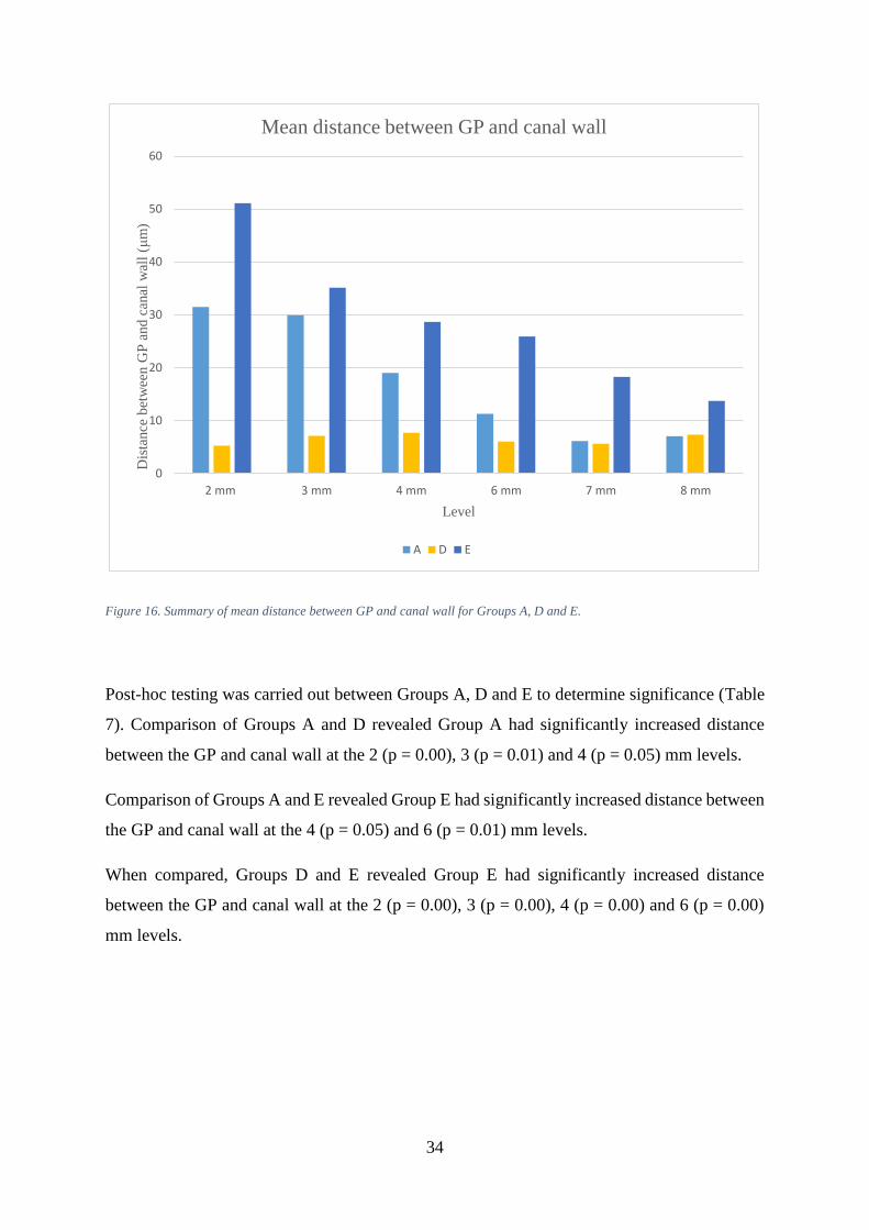
34
Figure 16. Summary of mean distance between GP and canal wall for Groups A, D and E.
Post-hoc testing was carried out between Groups A, D and E to determine significance (Table
7). Comparison of Groups A and D revealed Group A had significantly increased distance
between the GP and canal wall at the 2 (p = 0.00), 3 (p = 0.01) and 4 (p = 0.05) mm levels.
Comparison of Groups A and E revealed Group E had significantly increased distance between
the GP and canal wall at the 4 (p = 0.05) and 6 (p = 0.01) mm levels.
When compared, Groups D and E revealed Group E had significantly increased distance
between the GP and canal wall at the 2 (p = 0.00), 3 (p = 0.00), 4 (p = 0.00) and 6 (p = 0.00)
mm levels.
0
10
20
30
40
50
60
2 mm 3 mm 4 mm 6 mm 7 mm 8 mm
Dis
tance
bet
wee
n G
P a
nd
can
al w
all
(μm
)
Level
Mean distance between GP and canal wall
A D E

35
Table 7. Post-hoc comparisons of distance from GP to canal wall between Groups A, D and E.
Level A-D A - E D - E
Group with significantly
more sealer
Group with significantly
more sealer
Group with significantly
more sealer
2 mm A (p = 0.00) Not significant E (p = 0.00)
3 mm A (p = 0.01) Not significant E (p = 0.00)
4 mm A (p = 0.05) E (p = 0.05) E (p = 0.00)
6 mm Not significant E (p = 0.01) E (p = 0.00)
7 mm Not significant Not significant Not significant
8 mm Not significant Not significant Not significant
4.1.2 Roth 801 Root Canal Cement (Roth International) and the negative
control (Groups B, D and F)
The sum of 10 intercepts between the GP and canal wall for Groups B and F are shown in
Appendix C. Of the groups obturated with Roth 801 (Roth International), the largest sum of 10
intercepts occurred in Group F at the 2 mm level (381 μm). The mean distance between the GP
and canal wall for Groups B, D and F are shown in Table 6 and Figure 17. The largest mean
distance between the GP and canal wall occurred in Group F at the 2 mm level (38 μm).

36
Figure 17. Summary of mean distance between GP and canal wall for Groups B, D and F.
Post-hoc testing was carried out between Groups B, D and F to determine significance (Table
8). Comparison of Groups B and D revealed Group B had significantly increased distance
between the GP and canal wall at the 7 (p = 0.01) and 8 (p = 0.00) mm levels.
Comparison of Groups B and F revealed Group F had significantly increased distance between
the GP and canal wall at the 6 (p = 0.03) mm level only.
When compared, Groups D and F showed Group F had significantly increased distance
between the GP and canal wall at 6 (p = 0.03) and 8 (p = 0.00) mm.
0
5
10
15
20
25
30
35
40
45
2 mm 3 mm 4 mm 6 mm 7 mm 8 mm
Dis
tance
bet
wee
n G
P a
nd
can
al w
all
(μm
)
Level
Mean distance between GP and canal wall
B D F

37
Table 8. Post-hoc comparisons of distance from GP to canal wall between Groups B, D and F.
Level B-D B - F D - F
Group with significantly
more sealer
Group with significantly
more sealer
Group with significantly
more sealer
2 mm Not significant Not significant Not significant
3 mm Not significant Not significant Not significant
4 mm Not significant Not significant Not significant
6 mm Not significant F (p = 0.03) F (p = 0.03)
7 mm B (p = 0.01) Not significant Not significant
8 mm B (p = 0.00) Not significant F (p = 0.00)
4.1.3 Sealapex™ (Kerr) and the negative control (Groups C, D and G)
The sum of 10 intercepts between the GP and canal wall for Groups C and G are shown in
Appendix C. Of the groups obturated with Sealapex™ (Kerr), the largest sum of 10 intercepts
occurred in Group G at the 2 mm level (838 μm). The mean distance between the GP and canal
wall for Groups C, D and G are shown in Table 6 and Figure 18. The largest mean distance
between the GP and canal wall occurred in Group G at the 2 mm level (83 μm).

38
Figure 18. Summary of mean distance between GP and canal wall for Groups C, D and G.
Post-hoc testing was carried out between Groups C, D and G to determine significance (Table
9). Comparison of Groups C and D revealed Group C had significantly increased distance
between the GP and canal wall at the 2 (p = 0.02) and 4 (p = 0.00) mm levels, whilst Group D
had significantly increased distance at 7 (p = 0.00) and 8 (p = 0.00) mm.
Comparison of Groups C and G revealed Group G had significantly increased distance between
the GP and canal wall at the 8 mm (p = 0.03) level only.
When compared, Groups D and G showed Group G had significantly increased distance
between the GP and canal wall at the 2 (p = 0.00), 4 (p = 0.00), 7 (p = 0.01) and 8 (p = 0.00)
mm levels.
0
10
20
30
40
50
60
70
80
90
2 mm 3 mm 4 mm 6 mm 7 mm 8 mm
Dis
tance
bet
wee
n G
P a
nd
can
al w
all
(μm
)
Level
Mean distance between GP and canal wall
C D G

39
Table 9. Post-hoc comparisons of distance from GP to canal wall between Groups C, D and G.
Level C-D C - G D - G
Group with significantly
more sealer
Group with significantly
more sealer
Group with significantly
more sealer
2 mm C (p = 0.02) Not significant G (p = 0.00)
3 mm Not significant Not significant Not significant
4 mm C (p = 0.00) Not significant G (p = 0.00)
6 mm Not significant Not significant Not significant
7 mm D (p = 0.00) Not significant G (p = 0.01)
8 mm D (p = 0.00) G (p = 0.03) G (p = 0.00)
4.2 Sealer percentage in cross sections
At all levels, sealer percentage was found to be significantly different. Further post-hoc analysis
was performed to determine significance between the negative control (Group D) and each
sealer type.
The average sealer percentage for all groups combined is shown in Figure 19. The largest mean
sealer percentage occurs at the 2 mm level (24%) and the smallest at 8 mm (2%).

40
Figure 19. Mean sealer percentage of all groups combined.
4.2.1 AH Plus Jet™ (Dentsply DeTrey) and the negative control (Groups A, D
and E)
The mean sealer percentage in cross sections for Groups A and E are shown in Appendix D.
Of the groups obturated with AH Plus Jet™ (Dentsply DeTrey), the largest mean sealer
percentage occurred in Group A at the 2 mm level (52.5%).
Post-hoc testing was carried out between Groups A, D and E to determine significance (Table
10). Comparison of Groups A and D revealed Group A had significantly increased sealer at the
2 (p = 0.00), 3 (p = 0.00), 4 (p = 0.00), 6 (p = 0.00), 7 (p = 0.01) and 8 (p = 0.00) mm levels.
Comparison of Groups A and E revealed Group A had significantly increased sealer at the 2
mm (p = 0.03) level only.
When compared, Groups D and E showed Group E had significantly increased sealer at the 2
(p = 0.00), 3 (p = 0.00), 4 (p = 0.00), 6 (p = 0.00), 7 (p = 0.03), 8 (p = 0.00) mm levels.
0
5
10
15
20
25
30
2 mm 3 mm 4 mm 6 mm 7 mm 8 mm
Sea
ler
per
centa
ge
Level
Mean sealer percentage of all groups
Mean for all groups

41
Table 10. Post-hoc comparisons of sealer percentage between Groups A, D and E.
Level A-D A - E D - E
Group with significantly
increased sealer
percentage
Group with significantly
increased sealer
percentage
Group with significantly
increased sealer
percentage
2 mm A (p = 0.00) A (p = 0.03) E (p = 0.00)
3 mm A (p = 0.00) Not significant E (p = 0.00)
4 mm A (p = 0.00) Not significant E (p = 0.00)
6 mm A (p = 0.00) Not significant E (p = 0.00)
7 mm A (p = 0.01) Not significant E (p = 0.03)
8 mm A (p = 0.00) Not significant E (p = 0.00)
4.2.2 Roth 801 Root Canal Cement (Roth International) and the negative
control (Groups B, D and F)
The mean sealer percentage in cross sections for Groups B and F are shown in Appendix D. Of
the groups obturated with Roth 801 (Roth International), the largest mean sealer percentage
occurred in Group F at the 2 mm level (14.0 %).
Post-hoc testing was carried out between Groups B, D and F to determine significance (Table
11). Comparison of Groups B and D revealed Group B had significantly increased sealer at the
2 (p = 0.03), 3 (p = 0.00), 4 (p = 0.03), 6 (p = 0.03), 7 (p = 0.03) and 8 (p = 0.03) mm levels.
Comparison of Groups B and F revealed no significant difference at any level (p > 0.05).
When compared, Groups D and F showed Group F had significantly increased sealer at the 2
(p = 0.03), 6 (p = 0.00), 7 (p = 0.00), 8 (p = 0.01) mm levels.

42
Table 11. Post-hoc comparisons of sealer percentage between Groups B, D and F.
Level B-D B - F D - F
Group with significantly
increased sealer
percentage
Group with significantly
increased sealer
percentage
Group with significantly
increased sealer
percentage
2 mm B (p = 0.03) Not significant F (p = 0.03)
3 mm B (p = 0.00) Not significant Not significant
4 mm B (p = 0.03) Not significant Not significant
6 mm B (p = 0.03) Not significant F (p = 0.00)
7 mm B (p = 0.03) Not significant F (p = 0.00)
8 mm B (p = 0.03) Not significant F (p = 0.01)
4.2.3 Sealapex™ (Kerr) and the negative control (Groups C, D and G)
The mean sealer percentage in cross sections for Groups C and G are shown in Appendix D.
Of the groups obturated with Sealapex™ (Kerr), the largest mean sealer percentage occurred in
Group C at the 2 mm level (26.2 %).
Post-hoc testing was carried out between Groups C, D and G to determine significance (Table
12). Comparison of Groups C and D revealed Group C had significantly increased sealer at the
2 (p = 0.00), 3 (p = 0.00), 4 (p = 0.00), 6 (p = 0.01), 7 (p = 0.03) and 8 (p = 0.00) mm levels.
Comparison of Groups C and G revealed no significant difference at any level (p > 0.05).
When compared, Groups D and G revealed Group G had significantly increased sealer at the 2
(p = 0.00), 3 (p = 0.00), 4 (p = 0.00), 6 (p = 0.00), 7 (p = 0.01) and 8 (p = 0.01) mm levels.

43
Table 12. Post-hoc comparisons of sealer percentage between Groups C, D and G.
Level C-D C - G D - G
Group with significantly
increased sealer
percentage
Group with significantly
increased sealer
percentage
Group with significantly
increased sealer
percentage
2 mm C (p = 0.00) Not significant G (p = 0.00)
3 mm C (p = 0.00) Not significant G (p = 0.00)
4 mm C (p = 0.00) Not significant G (p = 0.00)
6 mm C (p = 0.01) Not significant G (p = 0.00)
7 mm C (p = 0.03) Not significant G (p = 0.01)
8 mm C (p = 0.00) Not significant G (p = 0.01)
4.2.4 The negative control (Group D)
The mean sealer percentage for Group D was 0% at the 2, 3, 4 and 6 mm levels. At 7 mm it
increased to 0.1% and at 8 mm 0.2% (Figure 20).

44
Figure 20. Mean sealer percentage for Group D.
4.3 Depth of sealer penetration
Descriptive analysis was performed on the depth of sealer penetration. Figure 21 shows sample
images of each penetration depth.
0
0.05
0.1
0.15
0.2
0.25
2 mm 3 mm 4 mm 6 mm 7 mm 8 mm
Sea
ler
per
centa
ge
Level
Summary of mean sealer percentage in cross section
D

45
Figure 21. Sample images showing penetration depths of the dyed sealer. Absent (top left), inner third (top right), middle
third (lower left) and outer third (lower right).
4.3.1 All groups
At all levels, the total count for each penetration depth was 606 absent, 594 inner third, 298,
middle third and 1016 outer third as shown in Figure 22 and Appendix E: Table E 1. At the 2
mm level, the most frequent penetration depth was inner (166) and the highest count (51)
occurred at the inner third in a buccal direction. At the 3 mm level, the most frequent
penetration depth was inner (161) and the highest count (47) also occurred at the inner third in
a buccal direction. At the 4 mm level, the most frequent penetration depth was absent (120)
and the highest count (37) was absent in a buccal direction. At the 6 mm level, the most frequent
penetration depth was outer (226) and the highest count (63) occurred at the outer third in a
mesial direction. At the 7 mm level, the most frequent penetration depth was outer (260) and
the highest count (68) occurred at the outer third in a mesial direction. At the 8 mm level, the
most frequent penetration depth was outer (286) and the highest count (78) occurred at the
outer third in a palatal direction.

46
Figure 22. Summary of penetration depths and direction of all groups at all levels.
When outer third penetration depth of all groups combined was analysed by level, the outer
penetration depth count was 56 at 2 mm and reached a maximum of 286 at 8 mm (Figure 23).

47
Figure 23. Outer penetration depth of all groups combined.
4.3.2 AH Plus Jet™ (Dentsply DeTrey) and the negative control (Groups A, D
and E)
For Group A (Figure 24 and Appendix E: Table E 2), the total count for each penetration depth
was 17 absent, 117 inner third, 92 middle third and 134 outer third. The total for Group E
(Figure 25 and Appendix E: Table E 6) was 43 absent, 118 inner, 41 middle and 158 outer.
When comparing the four penetration depths of Group A and E, Group E had more absent
penetrations at all levels, except 8 mm which was equivalent. Group E also had more inner
third penetration depths at 4 mm, 6 mm and 7 mm. The 3 mm and 8 mm levels were equivalent
and Group A had more at 2 mm. Group A had more middle third penetration depths at all levels
and Group E had more outer penetration depths at all levels except 6 mm.
For Group D (negative control) all penetration depths for all levels were scored “absent”
(Figure 26 and Appendix E: Table E 5). When Groups A and E were compared to Group D,
Group D scored more absent penetration depths at all levels. Group D scored fewer inner,
middle and absent penetration depths at all levels.
0
50
100
150
200
250
300
350
2 3 4 6 7 8
Co
un
t
Level
Outer penetration of all groups

48
Figure 24. Summary of Group A penetration depths and direction at all levels.

49
Figure 25. Summary of Group E penetration depths and direction at all levels.

50
Figure 26. Summary of Group D (negative control) penetration depths and direction at all levels.
4.3.3 Roth 801 Root Canal Cement (Roth International) and the negative
control (Groups B, D and F)
For Group B (Figure 27 and Appendix E: Table E 3), the total count for each penetration depth
was 39 absent, 100 inner third, 41 middle third and 180 outer third. The total for Group F
(Figure 28 and Appendix E: Table E 7) was 38 absent, 116 inner, 31 middle and 175 outer.
When comparing the four penetration depths of Group B and F, Group F had more absent
penetrations at 3 mm, 4 mm and 8 mm. The 7 mm level was equivalent and Group B had more

51
at 2 mm and 6 mm. Group F also had more inner third penetration depths at 2 mm, 6 mm and
8 mm. The 3 mm level was equivalent and Group B had more at 4 mm and 7 mm. Group B had
more middle third penetration depths at all levels except 6 mm. Group F had more outer
penetration depths at 2 mm, 4 mm and 7 mm whilst Group B had more at 3 mm, 6 mm and 8
mm.
When Groups B and F were compared to Group D (negative control) (Figure 26 and Appendix
E: Table E 5), Group D scored more “absent” penetration depths at all levels. Group D scored
fewer inner, middle and absent penetration depths at all levels.

52
Figure 27. Summary of Group B penetration depths and direction at all levels.

53
Figure 28. Summary of Group F penetration depths and direction at all levels.
4.3.4 Sealapex™ (Kerr) and the negative control (Groups C, D and G)
For Group C (Figure 29 and Appendix E: Table E 4), the total count for each penetration depth
was 71 absent, 73 inner third, 50 middle third and 166 outer third. The total for Group G (Figure
30 and Appendix E: Table E 6) was 48 absent, 70 inner, 39 middle and 203 outer.
When comparing the four penetration depths of Group C and G, Group C had more absent
penetrations at 2 mm, 4 mm and 6 mm. The 3 mm level was equivalent and Group G had more
at 7 mm and 8 mm. Group C also had more inner third penetration depths at all levels except 2

54
mm and 4 mm. Group C had more middle third penetration depths at 4 mm, 7 mm and 8 mm.
The 3 mm level was equivalent and Group G had more at 2 mm and 6 mm. Group G had more
outer penetration depths at all levels except 2 mm.
When Groups C and G were compared to Group D (negative control) (Figure 26 and Appendix
E: Table E 5), Group D scored more absent penetration depths at all levels. Group D scored
fewer inner, middle and absent penetration depths at all levels.
Figure 29. Summary of Group C penetration depths and direction at all levels.

55
Figure 30.Summary of Group G penetration depths and direction at all levels.

56
Chapter 5: Discussion
5.1 Gutta-percha adaptation to dentine
The distance between the GP and canal wall represents the sealer/film thickness as described
by other investigators. For all groups, the mean distance between the GP and canal wall were
found to be less than in the ex vivo study by de Deus et al. (2003) who recorded an average
sealer thickness of 88 μm. Their study compared obturation techniques with sealer thickness
and found the CWC technique to have a decreased thickness of sealer compared to lateral
condensation. That study, however, used a different tooth model (maxillary central incisors)
and a zinc-oxide eugenol sealer (Endofill). This is the same class of sealer as Roth’s. In
addition, de Deus et al. (2003) found a trend for increased sealer thickness in a coronal to apical
direction, which was a consistent finding for all groups in the current experiment except for the
negative control (Group D).
During root canal preparation, it was noted that some specimens had wider canals and others
narrow and calcified canals. After rotary preparation of specimens with the narrow canals, a
canal shape that closely corresponded to the matching MAC was created (Gordon et al. 2005).
Conversely, the specimens with wide canals were hardly instrumented with the size 40, 0.06
taper master apical file. As a result, when the root fillings were placed in wide canals, the
matching cone (size 40, 0.06 taper) would not correspond well to the shape of the ‘prepared’
but non-instrumented canal. The distance between the GP and root canal wall would therefore
be increased and filled with sealer. Consequently, the results for GP adaptation to dentine
would probably be increased. The CWC obturation technique generally improves GP
adaptation to dentine, however, it has a limited ability to effect the GP adaptation of the most
apical GP (Cusimano et al. 2010, Natera et al. 2011). The distance between the GP and canal
wall was lower in the middle and coronal portions of the canal. The effect of the down-pack
and backfill probably influenced these regions of the root canal, even if the MACs were poorly
adapted to those specimens with wide canals. Therefore, the variability of the canal
morphology and the CWCs inability to greatly affect the adaptation of apical GP accounted for
the trend for increased distance between the GP and canal wall from coronal to apical.
A plastic simulated tooth model has been used to assess GP adaptation to dentine (Gurgel‐Filho
et al. 2006, Karabucak et al. 2008). It would have circumvented the problem of large variations

57
in canal width and its effect on GP adaptation to dentine. A plastic model, however, would
have made the study less relevant to the clinical setting as it would not account for the complex
root canal morphology evident in human teeth (Vertucci 1984, Goldberg et al. 2002) and hence
extracted human teeth were utilised.
5.1.1 AH Plus Jet™ (Dentsply DeTrey) and the negative control (Groups A, D
and E)
5.1.1.1 Comparisons with the negative control
Compared to Group D (negative control), Group A had significantly increased distance
between the GP and canal wall at 2, 3 and 4 mm. Group E also had increased distances
compared to Group D at the 2, 3, 4 and 6 mm levels. This is to be expected as Group D was
only obturated with GP, while Group A and E were obturated with GP and sealer. It is to be
expected that as Group D had no sealer between the GP and canal wall that the distance between
the GP and canal wall would be decreased compared to Groups A and E.
5.1.1.2 Comparison between a single and an additional sealer application
The effect of a single and additional application of AH Plus or any other sealer during warm
obturation techniques has not been reported in the literature. Comparisons between Group A
and E revealed that Group E had significantly increased distance between the GP and canal
wall at the 4 and 6 mm levels only. This is a small but significant finding. Group A had only
one application of sealer, whilst Group E received the additional application. This suggests the
distance between the GP and canal wall mildly increased with an additional application of
sealer. This confirms the hypothesis for AH Plus and is an expected finding.
The average distance between the GP and canal wall for all levels was 17 μm for Group A and
29 μm for Group E. This was slightly higher than an ex vivo study which involved mandibular
molars (Weis et al. 2004) which reported an average sealer thickness of 12.2 μm after
obturation with the CWC technique. Their study, however, used AH 26, the predecessor of AH
Plus.

58
5.1.1.3 Influence of heat
The effect of warm obturation techniques on root canal sealers has been investigated. AH Plus
has recently been shown to be affected by high temperature (Viapiana et al. 2014b). It contains
dibenzyldiamine, aminoadamantane, and tricyclodecane-diamine in paste 1. These polyamines
act as initiators and react with the resins in paste 2, resulting in polymerization. The heat
disintegrates these phases (Viapiana et al. 2015). The effect of heating AH Plus to 25 and 37
has been shown not to influence viscosity (Lacey et al. 2006). This was in contrast to Camilleri
(2015) who investigated the effects of 100 °C heat for 1 min on AH Plus and found the sealer
properties were modified by heat. In addition, the setting time was reduced and the sealer film
thickness increased. As a consequence, AH Plus was not recommended for warm GP obturation
techniques. This finding is not relevant to the CWC obturation technique used in the current
study as the 0.06 taper heated plugger of the Elements™ Obturation Unit was only applied for
a total of 3 – 5 s in each canal rather than 1 min. In addition, the electronically heated pluggers
set to temperatures above 200 °C (on the display) have been shown to reach a maximum
temperature of only 80 °C (Viapiana et al. 2014b). Hence Camilleri (2015) and other
investigations (Qu et al. 2016) that show heat-related changes to AH Plus at 100 ˚C are not
relevant to the current investigation nor are they relevant to the CWC obturation technique used
in the clinical setting. This view is also shared by Al-Haddad (2017) and is an issue of current
debate in the journals.
5.1.2 Roth 801 Root Canal Cement (Roth International) and the negative
control (Groups B, D and F)
5.1.2.1 Comparisons with the negative control
Compared to Group D (negative control), Group B had significantly increased distance
between the GP and canal wall at 7 and 8 mm. Group F also had increased distances compared
to Group D at the 6 and 8 mm levels. This is to be expected as Group D was only obturated
with GP.

59
5.1.2.2 Comparison between a single and additional sealer application
The effect of a single and additional application of Roth’s during warm obturation techniques
has not been reported in the literature. Comparisons between Group B and F revealed Group F
had significantly increased distance between the GP and canal wall at the 6 mm level only.
Group B had only one application of sealer, whilst Group F had an additional application. This
suggests the distance between the GP and canal wall increased in the middle third with an
additional application of sealer. This is contrary to the hypothesis for Roth’s, as an increase
was only demonstrated in the middle third of the root and not the coronal third.
The average distance between the GP and canal wall for all levels was 17 μm for Group B and
18 μm for Group F. This was drastically lower than de Deus et al. (2003) who found an average
film thickness of sealer of 88 μm. Analysis by root third revealed the average distance for the
apical, middle and coronal was 26, 12 and 11 μm for Group B and 25, 19 and 9 μm for Group
F. When compared to de Deus et al. (2003) it was found to be up to seven times less, with
average film thicknesses of 187 apically, 47 mid-root and 29 μm coronally. It is important to
note that the other workers used a different tooth model (maxillary central incisors) and sealer
(Endofill). Although the sealer is different, it is the same sealer class as Roth’s and should
therefore be somewhat comparable.
5.1.2.3 Influence of heat
The effect of heat on the physical properties of Roth’s sealer has not been reported in the
literature. Pulp Canal Sealer is a zinc oxide euginol-based sealer. Camilleri (2015) investigated
the effects of 100 °C heat for 1 min on Pulp Canal Sealer and found the setting time and sealer
film thickness were unaffected by heat. As this is the same class of sealer as Roth’s, a similar
outcome would be expected.

60
5.1.3 Sealapex™ (Kerr) and the negative control (Groups C, D and G)
5.1.3.1 Comparisons with the negative control
Compared to Group D (negative control), Group C had a significantly increased distance
between the GP and canal wall at 2 and 4 mm whilst Group D had significantly increased
distance at 7 and 8 mm. The difference was 4 and 3 μm more than Group D between the groups
at the 7 and 8 mm levels, however, it was significant. The decreased distance of Group D is to
be expected as it was only obturated with GP. It is also to be expected that as Group D had no
sealer, the distance between the GP and canal wall would be decreased compared to groups
obturated with sealer. Group G also had increased distances compared to Group D at the 2, 4,
7 and 8 mm levels. Again, it is to be expected that Group D without sealer would have less
distance between GP and the canal wall.
5.1.3.2 Comparison between a single and an additional sealer application
The effect of a single and additional application of Sealapex™ during warm obturation
techniques has not been reported in the literature. Comparisons between Group C and G
revealed Group G had significantly increased distance between the GP and canal wall at the 8
mm level only. Group C had only a single application of sealer, whilst Group G had an
additional application. This suggests the distance between the GP and canal wall increased in
the coronal third with an additional application of sealer. This is contrary to the hypothesis, as
an increase was only demonstrated in the coronal third of the root and not the middle third.
The average distance between the GP and canal wall for all levels was 22 μm for Group C and
35 μm for Group G. There are no studies on Sealapex™ or calcium other hydroxide-based sealer
thickness after warm vertical obturation techniques. However, the distance between the GP and
canal wall was comparable to Weis et al. (2004) who reported an average sealer thickness of
12.2 μm after CWC was performed on mandibular molars. It was also substantially less than
de Deus et al. (2003) who reported an average film thickness of 88 μm with CWC performed
on maxillary central incisors. Both studies, however, used different sealers.
The largest mean distance between the GP and canal wall for all groups at all levels was
measured at 84 μm for Group G. The Sealapex™ sealer groups (Groups C and G) tended to
have larger distances at the 2, 3 and 4 mm levels when compared to the other sealers but this

61
was only significant at 2 and 4 mm when compared with Roth’s. There is little evidence in the
literature to suggest why this may occur, but it may be attributed to the physical properties of
calcium hydroxide-based sealers.
5.1.3.3 Influence of heat
The effect of heat on the physical properties of Sealapex™ have not been reported in the
literature. Apexit Plus is a calcium hydroxide-based sealer. Camilleri (2015) investigated the
effects of 100 °C heat for 1 min on Apexit Plus and found the setting time and sealer film
thickness were unaffected by heat. As this is the same class of sealer as Sealapex™, the outcome
should be somewhat comparable.
5.2 Sealer percentage in cross sections
The mean percentage of sealer for each level is shown in Appendix D. The mean sealer
percentage for all groups at 2 mm was 24% and decreased at 8 mm to 2%. The percentage of
sealer in all groups tended to decrease from apical to coronal. This is a common finding
amongst other investigators, although some report GP percentage rather than sealer percentage
(Smith et al. 2000, Keçeci et al. 2005). This cannot be directly compared between studies
became voids and canal debris may influence the results. It does, however, provide an
indication of sealer percentage and show potential trends.
Silver et al. (1999) and Cathro and Love (2003) have reported low percentages of sealer in
cross sections after the CWC obturation technique with a single application of sealer. Silver’s
group (1999) reported sealer percentage values of 2 – 5% measured at 1, 2, 3, 4, 5, 6 mm from
the root apex. This is markedly lower than the sealer percentages found in the current
investigation which ranged from 0 – 53%. Cathro and Love (2003) reported even lower sealer
percentages, ranging from 0 – 4% measured at 10 levels along the root length. These
investigators used a different sealer (Kerr Pulp Canal Sealer EWT) and plastic simulation
models rather than account for the complex canal irregularities evident in human teeth
(Vertucci 1984).

62
Investigations on extracted human teeth reveal high GP percentages in cross sections after the
CWC with a single application of sealer. Wu et al. (2001) obturated teeth with a multiple wave
technique using AH 26 and reported a percentage of GP of 94% at 2 mm and 100% 4 mm from
the root apex. This is a very high percentage of GP. In the current investigation, sealer
percentage varies significantly from 4 – 53% at the 2 - 4 mm levels across all experimental
groups with an average sealer percentage of 20%. Although direct comparisons between GP
and sealer percentage are not strictly applicable, the sealer percentage is much higher in the
current investigation compared with Wu et al. (2001). Gençoǧlu et al. (2002) obturated teeth
with Kerr Pulp Canal Sealer EWT using a warm vertical technique similar to the CWC method.
They also reported a higher percentage of GP, between 81 – 9%, 1 – 4 mm from the root apex.
The study, however, advanced the electrically heated plugger 3 mm from the WL which is
much further than the current investigation where it was only 5-7 mm from the WL. This is a
significant difference in the methodology as heat application closer to the WL has been shown
to improve GP adaptation and produce higher percentages of GP (Smith et al. 2000, Jung et al.
2003).
5.2.1 AH Plus Jet™ (Dentsply DeTrey) and the negative control (Groups A, D
and E)
5.2.1.1 Comparisons with the negative control (Group D)
Sealer percentage in cross sections were found to be significantly different at all levels. Post-
hoc comparisons between Groups A, D and E were significant. Compared to Group D (negative
control), Groups A and E had significantly increased sealer at all levels. This is to be expected
as Group D was only obturated with GP, whilst Group A and E were obturated with GP and a
single or double application of sealer. Group D never had sealer applied, therefore, the sealer
percentage would be expected to be decreased compared to Groups A and E.
5.2.1.2 Comparison between a single and an additional sealer application
The effect of a single and additional application of AH Plus during warm obturation techniques
has not been reported in the literature. Comparisons between Groups A and E revealed Group
A had significantly increased sealer percentage at 2 mm only. This is a small but statistically

63
significant finding. Group A had only one application of sealer, whilst Group E had an
additional application. This suggests the sealer percentage at the apical third slightly decreased
with an additional application of sealer. This is contrary to the hypothesis for AH Plus and is
an unexpected finding.
5.2.2 Roth 801 Root Canal Cement (Roth International) and the negative
control (Groups B, D and F)
5.2.2.1 Comparisons with the negative control (Group D)
Sealer percentage in cross section was found to be significantly different at all levels. Post-hoc
comparisons between Groups B, D and F were significant. Compared to Group D (negative
control), Groups B and F had significantly increased sealer at all levels. This is to be expected
as Group D was only obturated with GP, whilst Group B and F were obturated with GP and a
single or double application of sealer. Group D never had sealer applied, therefore, the sealer
percentage would be expected to be decreased compared to Groups B and F.
5.2.2.2 Comparison between a single and an additional sealer application
The effect of a single and additional application of Roth’s during warm obturation techniques
has not been reported in the literature. Comparisons between Groups B and F revealed no
significant differences at any level. Group B had a single application of sealer whilst Group F
had an additional application. This suggests no difference at any level between a single and
additional application of Roth’s on sealer percentage in cross section. This is contrary to the
hypothesis for this sealer.
5.2.3 Sealapex™ (Kerr) and the negative control (Groups C, D and G)
5.2.3.1 Comparisons with the negative control (Group D)
Sealer percentage in cross section was found to be significantly different at all levels. Post-hoc
comparisons between Groups C, D and G were significant. Compared to Group D (negative
control), Groups C and G had significantly increased sealer at all levels. This is to be expected

64
as Group D was only obturated with GP, whilst Group C and G were obturated with GP and a
single or double application of sealer. Group D never had sealer applied, therefore, the sealer
percentage would be expected to be lower to that of Group C.
5.2.3.2 Comparison between a single and an additional sealer application
The effect of a single and additional application of Sealapex™ has not been reported in the
literature. Comparisons between Groups C and G revealed no significant differences at any
level. Group C had a single application of sealer whilst Group G had an additional application.
This suggests no difference at any level between a single and additional application of
Sealapex™ on sealer percentage in cross section. This is contrary to the hypothesis for
Sealapex™.
5.2.4 The negative control (Group D)
The sealer percentage in Group D was usually 0%. Zero sealer percentage in cross section is
expected, however, at the 7 and 8 mm levels small sealer amounts were recorded. This is
attributed to an unfortunate shortcoming of the use of the Image J software. In the analysis, the
pixel count of each area represented by dyed sealer within the root-filled canal was then
calculated and expressed as a percentage of the total canal area. The small but “positive” sealer
measured in the 7 and 8 mm levels was probably the result of the program detecting dark pixels
as ‘sealer.’ This was sometimes evident with the presence of a void or discoloured dentine
debris (Figure 31 and Figure 32).

65
Figure 31. Cross section of Group D at 7 mm with void (arrow).
Figure 32. Dentine debris (arrow) evident in a cross section of Group D.

66
5.3 Depth of sealer penetration
5.3.1 All groups
Primary dentine is influenced by ageing (Ketterl 1983) and the amount of dentinal tubular
sclerosis increases with age. It begins at the root apex, adjacent to the cementum and gradually
advances towards the crown. When all groups and levels were combined, the highest
penetration depth count was the outer third (n = 1016). The outer penetration depth count was
lowest at the 2 mm level (n = 56) and increased in a coronal direction, at each level to reach a
maximum of 286 at the 8 mm level. Other investigators also reported increased penetration
depths in an apical to coronal direction (Kara Tuncer 2015, Akcay et al. 2016, Gu et al. 2017,
Turkel et al. 2017). This is an expected finding as the sclerosis of the dentine has been
attributed to tubular penetration inhibition (Paqué et al. 2006).
5.3.2 Direction of sealer penetration
Differences in sealer penetration direction were also observed. For all experimental groups
except for Group E, the highest count of outer third penetration depths was recorded in the
buccal or palatal direction at the 2 and 3 mm levels. This is a significant finding as dentinal
tubular sclerosis begins first apically (Ketterl 1983) and mesially and distally creating a distinct
butterfly shape (Vasiliadis et al. 1983). As a consequence, sealer penetration in the sclerosed
mesial and distal directions will be impeded (Paqué et al. 2006) and increased penetration depth
counts are expected for the buccal and palatal directions. Similar findings were observed by
Weis et al. (2004) who obturated mesial roots of extracted human mandibular molars with four
obturation techniques including CWC. They found the obturation technique did not affect
sealer penetration depths, and that penetration depths were greater and more frequent in a bucco
- lingual direction.
5.3.3 Comparisons with the negative control (Group D)
The total count for each penetration depth for Group D was 660 absent and 0 inner, middle and
outer third. This is an expected finding as Group D was obturated with no sealer, therefore

67
sealer penetration into the dentine is impossible. When all other groups were compared with
Group D, they each showed increased inner, middle and outer third penetration depth counts at
each level. This is an expected finding as Group D never had sealer applied.
5.3.4 AH Plus Jet™ (Dentsply DeTrey) and the negative control (Groups A, D
and E)
5.3.4.1 Comparison between a single and an additional sealer application
Comparisons between Groups A and E revealed the total count for each penetration depth for
Group A was 17 absent, 117 inner third, 92 middle and 134 outer. This was generally similar
to Group E (43 absent, 118 inner third, 41 middle third and 158 outer third). Group E did,
however, present increased outer third penetration depths.
At each level, Group E had more outer third penetration depths, except 6 mm. This suggests a
trend for increased sealer penetration with an additional application of sealer. This is consistent
with the hypothesis for AH Plus. Group E was expected to have increased sealer penetration
depth counts in the middle and coronal root thirds, however, increased outer third penetration
depths were also observed in the apical root.
5.3.5 Roth 801 Root Canal Cement (Roth International) and the negative
control (Groups B, D and F)
5.3.5.1 Comparison between a single and additional sealer application
Comparisons between Groups B and F revealed the total count for each penetration depth for
Group B was 78 absent, 193 inner third, 76 middle and 313 outer. This was generally similar
to Group F (73 absent, 221 inner third, 58 middle third and 308 outer third). Group F did,
however, observe increased inner third penetration depths.
At the 2, 4 and 7 mm levels, Group F had more outer third penetration depth counts whilst
Group B had more at 3, 6 and 8 mm. Each group had more outer third penetration depth counts
at alternating levels. This suggests an additional application of sealer did not affect the depth
of penetration, which is contrary to the hypothesis for Roth’s.

68
5.3.6 Sealapex™ (Kerr) and the negative control (Groups C, D and G)
5.3.6.1 Comparison between a single and an additional sealer application
Comparisons between Groups C and G revealed the total count for each penetration depth for
Group C was 142 absent, 141 inner third, 93 middle and 284 outer. This was generally similar
to Group G (95 absent, 140 inner third, 73 middle third and 352 outer third). Group F did,
however, observe increased outer third penetration depths.
At each level, Group F had more outer third penetration depths, except at the 2 mm level. This
suggests a trend for increased sealer penetration with the additional application of sealer and is
consistent with the hypothesis for Sealapex™. Group F was expected to have increased sealer
penetration depths in the middle and coronal root thirds, however, increased outer third
penetration depth counts were also observed in the apical root.
5.4 Sealer flow
The ISO6876 (2012) (Institution 2012) specifications dictate the physical properties of root
canal sealers, such as flow. Sealer flow is measured by placing a designated volume of the
mixed sealer between two glass slabs with a weight for compression. The mean diameter of the
compressed disc of sealer is measured to determine the flow.
The physical properties and characteristics of a root canal sealer are fundamental to their
clinical behaviour. Flow allows a sealer to penetrate into the irregularities of the root canal
system (Silva et al. 2013). Root canal sealers with excessive flow run the risk of extrusion
beyond the apex. The ISO6876 (2012) specifications specify the flow of a sealer should be
greater than 17 mm in diameter. AH Plus has been shown to have a flow between 17 – 23 mm
(Viapiana et al. 2014a, Khalil et al. 2016) which is comparable to Roth’s with a flow of 20 mm
(Grossman 1976c) and Sealapex™ 19 mm (Almeida et al. 2007, Viapiana et al. 2014a). The
similar flow of the sealers tested means that flow probably had little impact on the results of
the study.

69
5.5 Experimental design and study limitations
5.5.1.1 Specimens
Palatal roots of maxillary molar teeth were utilised for the study as it was envisaged that the
sufficient numbers of these teeth could be collected within the limited time frame the research
was to be conducted in. Single rooted teeth were deliberately not chosen as other investigators
from the university were already collecting these teeth. In order to collect a sufficient sample
size, the collection time of the specimens would have increased beyond an acceptable range,
thus palatal roots of maxillary molar teeth were chosen. The morphology of palatal roots of
maxillary molar teeth has been shown to vary from that of single rooted teeth (Vertucci 2005),
as a consequence, the results cannot be extrapolated to single rooted teeth. Attempts were made
to standardise the teeth collected by specifying inclusion and exclusion criteria. This was
intended to produce specimens with similar root canal morphology. An age range of
participants at the time of extraction was not included. This resulted in variations in root canal
diameter (Pineda & Kuttler 1972). Some specimens had wider canals whilst others had narrow
and calcified canals. The specimens with narrow canals required more preparation time to take
a size 10 K-file to the apical foramen and more dentine was ultimately removed during
instrumentation procedures. Conversely, the specimens with wide canals were hardly
instrumented with the size 40, 0.06 taper master apical file. This meant that when the root
fillings were placed in wide canals, the matching cone (size 40, 0.06 taper) would not
correspond well to the shape of the ‘prepared’ root canal. The distance between the GP and
root canal wall may be increased and may have been filled with sealer, increasing the sealer
percentage. Consequently, the results for GP adaptation to dentine and the sealer percentage
fill would be influenced based on variations in root canal morphology. In a clinical setting,
instrumentation of root canals is performed with files that are typically larger than the original
anatomy of the main canal. This is performed with instruments of sufficient size and taper. This
would mean that matching cone would correspond well to the root canal, decreasing sealer
percentage and the distance between the GP and canal wall.

70
5.5.1.2 Root canal fillings
Obturation with the CWC method was difficult to completely standardise. During the down-
pack, a 0.06 taper heated plugger of an Elements™ Obturation Unit was activated and inserted
to 5-7 mm from the WL. This left a 2 mm variation of placement of the plugger. The power
was then deactivated and the plugger was pushed apically for 10 s. When pushing apically,
sometimes the plugger was advanced several millimetres and at other times could not be
advanced. Heat was again applied for 1 s and after waiting a further second, the plugger was
removed. The 2 mm variation of the placement of the variation plugger and variation in the
distance the plugger was apically advanced were uncontrolled variables that may have
influenced the results.
Sudan Black B, a histological stain for lipids, is an excellent stain for implanted polymeric
biomaterials such as glycol methacrylate and epoxy resins (Hoeksma et al. 1988). It was used
in a previous ex vivo study that measured sealer thickness and dentine penetration (Weis et al.
2004). They found the dye was completely soluble in sealer and the handling and setting
characteristics of the sealer were not affected. It was also determined that the dye provided
sufficient contrast against dentine and GP and allowed microscopic evaluation of sealer
thickness and penetration. Their study used AH 26, and although the same class of sealer as
AH Plus, this was different to the sealers used in the current study and it may have affected the
sealer handling and setting characteristics. Caution may be advisable extrapolating the results
of the study to the clinical use of sealers not dyed with Sudan Black B.
The dispensing and mixing of the sealers was not standardised. AH Plus was mixed in an auto-
mixing syringe as it was dispensed. A similar type of mixing and dispensing tip would have
been a superior method of dispensing the Sealapex™sealer to improve standardisation.
Difficulties in standardisation were also encountered with the addition of the dye. Each sealer
was mixed according to the manufacturer’s instructions and was coloured with a small amount
of dye added until completely dissolved. The exact amount of dye was not strictly controlled
and this may have influenced the results. The volume of sealer applied to each canal was also
not strictly standardised. All sealers were placed using a size 25 Pastinject™ in a slow-speed
handpiece by coating the flutes in sealer and introducing it into the canal, 1 mm from the WL.
The Pastinject™ was then rotated clockwise for 5 s before withdrawing it from each canal.
There will be variations in the volume of sealer carried by the flutes of the instrument. The

71
MACs were also coated with sealer before insertion with a pumping action. Again, variations
in the volume of sealer are likely.
5.5.2 Evaluation
All data were analysed by a single examiner. To improve reliability and repeatability of the
measurements, multiple examiners should have evaluated the data and kappa scores produced
to show inter-examiner reliability.
5.5.2.1 Sealer percentage
During evaluation of sealer percentage, computer software (Image J) was used to determine
the pixel count of each area representing dyed sealer within the root-filled canal. This was then
calculated and expressed as a percentage of the total canal area. The dye may have also
discoloured and affected the GP and surrounding dentine. This is an inaccuracy that is a
limitation of all dyed sealer investigations (Weis et al. 2004).
5.5.2.2 Depth of penetration
Nine of the teeth exhibited a crack when viewed under high magnification (10x). This may
have been for a number of reasons, such as damage during tooth extraction, rotary nickel
titanium induced stress (Adorno et al. 2011) or the tooth may have suffered a vertical root
fracture prior to extraction. The dyed sealer tended to travel further through cracks which
helped to visualise them (Wright et al. 2004). Higher sealer penetrations through the dentine
were observed in teeth exhibiting cracks.

72
5.6 Conclusion
Within the limitations of this study, the distance between the GP and canal wall as well as
sealer percentage in cross sections decreased from apical to coronal for all experimental groups.
The number of outer third penetration depths, however, increased in an apical to coronal
direction.
Comparisons with the negative control revealed significantly increased distance between the
GP and canal wall, increased sealer percentage in cross sections at most levels and deeper and
more frequent penetration depths for each group.
For each sealer, an additional application of sealer increased the distance between the GP and
canal wall to a minor degree. It had no effect on Roth’s and Sealapex™ but decreased the sealer
percent of AH Plus Jet™ to a minor degree and increased the outer third penetration depths for
AH Plus Jet™ and Sealapex™ but not Roth’s.

73
References
Adorno CG, Yoshioka T, Suda H (2011) Crack initiation on the apical root surface caused by
three different nickel-titanium rotary files at different working lengths. Journal of Endodontics
37, 522-5.
Aguirre AM, El Deeb ME, Aguirre R (1997) The effect of ultrasonics on sealer distribution
and sealing of root canals. Journal of Endodontics 23, 759-64.
Akcay M, Arslan H, Durmus N, Mese M, Capar ID (2016) Dentinal tubule penetration of AH
Plus, iRoot SP, MTA Fillapex, and GuttaFlow Bioseal root canal sealers after different final
irrigation procedures: A confocal microscopic study. Lasers in Surgery and Medicine 48, 70-
6.
Al-Dewani N, Hayes SJ, Dummer PMH (2000) Comparison of laterally condensed and low-
temperature thermoplasticized gutta-percha root fillings. Journal of Endodontics 26, 733-8.
Al-Haddad AY (2017) Letter to the Editor: Warm Vertical Compaction and Its Influence on
the Properties of Root Canal Sealers. Journal of Endodontics 43, 1229.
Allan NA, Walton RE, Schaffer M (2001) Setting times for endodontic sealers under clinical
usage and in vitro conditions. Journal of Endodontics 27, 421-3.
Almeida JF, Gomes BP, Ferraz CC, Souza-Filho FJ, Zaia AA (2007) Filling of artificial lateral
canals and microleakage and flow of five endodontic sealers. International Endodontic Journal
40.
Anantula K, Ganta AK (2011) Evaluation and comparison of sealing ability of three different
obturation techniques — Lateral condensation, Obtura II, and GuttaFlow: An in vitro study.
Journal of Conservative Dentistry 14, 57-61.

74
Andreasen J (1987) Experimental dental traumatology: development of a model for external
root resorption. Dental Traumatology 3, 269-87.
Aneet BAS, Hicks LM, Fredrick B (2001) Comparison of laterally condensed .06 and .02
tapered gutta-percha and sealer in vitro. Journal of Endodontics 27, 786-8.
Araki K, Suda H, Barbosa SV, Spångberg LS (1993) Reduced cytotoxicity of a root canal sealer
through eugenol substitution. Journal of Endodontics 19, 554-7.
Augsburger RA, Peters DD (1990) Radiographic evaluation of extruded obturation materials.
Journal of Endodontics 16, 492-7.
Bailey G, Ng YL, Cunnington S, Barber P, Gulabivala K, Setchell D (2004) Root canal
obturation by ultrasonic condensation of gutta‐percha. Part II: an in vitro investigation of the
quality of obturation. International Endodontic Journal 37, 694-8.
Barros J, Silva M, Rodrigues M, Alves F, Lopes M, Pina‐Vaz I, Siqueira J (2014) Antibacterial,
physicochemical and mechanical properties of endodontic sealers containing quaternary
ammonium polyethylenimine nanoparticles. International Endodontic Journal 47, 725-34.
Benenati FW (2008) Obturation of the radicular space. Ingle's Endodontics, 6 edn; pp. 1053-
87: BC Decker, Ontario, Canada.
Boiesen J, Brodin P (1991) Neurotoxic effect of two root canal sealers with calcium hydroxide
on rat phrenic nerve in vitro. Dental Traumatology 7, 242-5.
Bowman CJ, Baumgartner JC (2002) Gutta-percha obturation of lateral grooves and
depressions. Journal of Endodontics 28, 220-3.
Brady JM, del Rio CE (1975) Corrosion of endodontic silver cones in humans: a scanning
electron microscope and X-ray microprobe study. Journal of Endodontics 1, 205-10.

75
Buchanan S (1994) The continuous wave of condensation technique: a convergence of
conceptual and procedural advances in obturation. Dentistry Today 13, 80, 2, 4-5.
Buckley M, Spångberg LSW (1995) The prevalence and technical quality of endodontic
treatment in an American subpopulation. Oral Surgery, Oral Medicine, Oral Pathology, Oral
Radiology, and Endodontology 79, 92-100.
Camilleri J (2015) Sealers and warm gutta-percha obturation techniques. Journal of
Endodontics 41, 72-8.
Cathro PR, Love RM (2003) Comparison of MicroSeal and System B/Obtura II obturation
techniques. International Endodontic Journal 36, 876-82.
Chogle S, Mickel AK, Huffaker SK, Neibaur B (2005) An in vitro assessment of iodoform
gutta-percha. Journal of Endodontics 31, 814-6.
Chugal NM, Clive JM, Spångberg LSW (2003) Endodontic infection: some biologic and
treatment factors associated with outcome. Oral Surgery, Oral Medicine, Oral Pathology, Oral
Radiology, and Endodontology 96, 81-90.
Cohen BI, Pagnillo MK, Musikant BL, Deutsch AS (1998) Formaldehyde evaluation from
endodontic materials. Oral Health 88, 37-9.
Collins J, Walker MP, Kulild J, Lee C (2006) A comparison of three gutta-percha obturation
techniques to replicate canal irregularities. Journal of Endodontics 32, 762-5.
Curson I, Kirk E (1968) An assessment of root canal-sealing cements. Oral Surgery, Oral
Medicine, Oral Pathology 26, 229-36.
Cusimano P, Cumbo EM, Provenzano S, Goracci C, Gallina G, Ferrari M (2010) Assessment
of gutta-percha adaptation with different root canal obturation techniques. Dental Materials
26, e68-e9.

76
Dahl JE (2005) Toxicity of endodontic filling materials. Endodontic Topics 12, 39-43.
de Deus GA, Gurgel‐Filho ED, Maniglia‐Ferreira C, Coulinho‐Filho T (2004) The influence
of filling technique on depth of tubule penetration by root canal sealer: a study using light
microscopy and digital image processing. Australian Endodontic Journal 30, 23-8.
de Deus GA, Martins F, Lima ACMR, Gurgel-Filho ED, Maniglia CF, Coutinho-Filho T
(2003) Analysis of the film thickness of a root canal sealer following three obturation
techniques. Pesquisa Odontológica Brasileira 17, 119-25.
Deitch AK, Liewehr FR, West LA, Patton WR (2002) A comparison of fill density obtained
by supplementing cold lateral condensation with ultrasonic condensation. Journal of
Endodontics 28, 665-7.
Desai S, Chandler N (2009) Calcium hydroxide–based root canal sealers: a review. Journal of
Endodontics 35, 475-80.
Duarte MAH, de Oliveira Demarchi ACC, Giaxa MH, Kuga MC, de Campos Fraga S, de Souza
LCD (2000) Evaluation of pH and calcium ion release of three root canal sealers. Journal of
Endodontics 26, 389-90.
Eleazer P, Glickman G, McClanahan S, Webb T, Justman B (2012) Glossary of Endodontic
Terms. Chicago, IL: American Association of Endodontists.
Emmanuel S, Shantaram K, Sushil KC, Manoj L (2013) An in-vitro evaluation and comparison
of apical sealing ability of three different obturation technique - lateral condensation, Obtura
II, and Thermafil. Journal of International Oral Health 5, 35-43.
Ersev H, Schmalz G, Bayirli G, Schweikl H (1999) Cytotoxic and mutagenic potencies of
various root canal filling materials in eukaryotic and prokaryotic cells in vitro. Journal of
Endodontics 25, 359-63.

77
Farzaneh M, Abitbol S, Lawrence HP, Friedman S (2004) Treatment outcome in endodontics—
the Toronto Study. Phase II: initial treatment. Journal of Endodontics 30, 302-9.
Fors U, Jonasson E, Bergquist A, Berg JO (1985) Measurements of the root surface temperature
during thermo‐mechanical root canal filling in vitro. International Endodontic Journal 18, 199-
202.
Froes FGB, Miranda ÁMMA, Abad EDC, Riche FN, Pires FR (2009) Non‐surgical
management of paraesthesia and pain associated with endodontic sealer extrusion into the
mandibular canal. Australian Endodontic Journal 35, 183-6.
Gee D (1998) Effect of tubule orientation in the cavity wall on the seal of dental filling
materials: an in vitro study. International Endodontic Journal 31, 326-32.
Gençoǧlu N, Garip Y, Baş M, Samani S (2002) Comparison of different gutta-percha root
filling techniques: Thermafil, Quick-fill, System B, and lateral condensation. Oral Surgery,
Oral Medicine, Oral Pathology, Oral Radiology, and Endodontology 93, 333-6.
Gilhooly RM, Hayes SJ, Bryant ST, Dummer PM (2001) Comparison of lateral condensation
and thermomechanically compacted warm α-phase gutta-percha with a single cone for
obturating curved root canals. Oral Surgery, Oral Medicine, Oral Pathology, Oral Radiology,
and Endodontology 91, 89-94.
Goldberg F, Artaza LP, De Silvio AC (2002) Influence of calcium hydroxide dressing on the
obturation of simulated lateral canals. Journal of Endodontics 28, 99-101.
Gordon MPJ, Love RM, Chandler NP (2005) An evaluation of .06 tapered gutta-percha cones
for filling of .06 taper prepared curved root canals. International Endodontic Journal 38, 87-
96.

78
Gound TG, Riehm RJ, Makkawy HA, Odgaard EC (2000) A description of an alternative
method of lateral condensation and a comparison of the ability to obturate canals using
mechanical or traditional lateral condensation. Journal of Endodontics 26, 756-9.
Grossman LI (1976a) Endodontics 1776–1976: a bicentennial history against the background
of general dentistry. Journal of the American Dental Association 93, 78-87.
Grossman LI (1976b) Physical properties of root canal cements. Journal of Endodontics 2,
166-75.
Grossman LI (1976c) Physical properties of root canal cements. Journal of Endodontics 2, 166-
75.
Grossman LI (1978) Obturation of the canal. Endodontic Practice, 9 edn; pp. 275-321.
Philadelphia: Lea & Febiger.
Gu Y, Perinpanayagam H, Kum DJ, Yoo Y-J, Jeong J-S, Lim S-M, Chang S-W, Baek S-H,
Zhu Q, Kum K-Y (2017) Effect of Different Agitation Techniques on the Penetration of Irrigant
and Sealer into Dentinal Tubules. Photomedicine and Laser Surgery 35, 71-7.
Gurgel‐Filho E, Feitosa J, Gomes B, Ferraz C, Souza‐Filho F, Teixeira F (2006) Assessment
of different gutta‐percha brands during the filling of simulated lateral canals. International
Endodontic Journal 39, 113-8.
Gutierrez J, Brizuela C, Villota E (1999) Human teeth with periapical pathosis after
overinstrumentation and overfilling of the root canals: a scanning electron microscopic study.
International Endodontic Journal 32, 40-8.
Gutmann JL, Rakusin H, Powe R, Bowles WH (1987) Evaluation of heat transfer during root
canal obturation with thermoplasticized gutta-percha. Part II. In vivo response to heat levels
generated. Journal of Endodontics 13, 441-8.

79
Gutmann JL, Saunders W, Saunders E, Nguyen L (1993) An assessment of the plastic
Thermafil obturation technique. International Endodontic Journal 26, 173-8.
Hardie EM (1986) Heat transmission to the outer surface of the tooth during the thermo‐
mechanical compaction technique of root canal obturation. International Endodontic Journal
19, 73-7.
Harvey TE, White JT, Leeb IJ (1981) Lateral condensation stress in root canals. Journal of
Endodontics 7, 151-5.
Heck dHA, Casanova M, Starr TB (1990) Formaldehyde toxicity—new understanding.
Critical Reviews in Toxicology 20, 397-426.
Heling I, Chandler NP (1996) The antimicrobial effect within dentinal tubules of four root
canal sealers. Journal of Endodontics 22, 257-9.
Himel VT, Cain CW (1993) An evaluation of the number of condenser insertions needed with
warm lateral condensation of guttapercha. Journal of Endodontics 19, 79-82.
Hoeksma E, Van Der Lei B, Jonkman M (1988) Sudan black B as a histological stain for
polymeric biomaterials embedded in glycol methacrylate. Biomaterials 9, 463-5.
Holcomb JQ, Pitts DL, Nicholls JI (1987) Further investigation of spreader loads required to
cause vertical root fracture during lateral condensation. Journal of Endodontics 13, 277-84.
Hommez G, De Moor R, Braem M (2003) Endodontic treatment performed by Flemish
dentists. Part 2. Canal filling and decision making for referrals and treatment of apical
periodontitis. International Endodontic Journal 36, 344-51.
Hoskinson SE, Ng Y-L, Hoskinson AE, Moles DR, Gulabivala K (2002) A retrospective
comparison of outcome of root canal treatment using two different protocols. Oral Surgery,
Oral Medicine, Oral Pathology, Oral Radiology, and Endodontology 93, 705-15.

80
Huang T-H, Huei Lee DMS, Kao C-T (2001) Evaluation of the genotoxicity of zinc oxide
eugenol-based, calcium hydroxide-based, and epoxy resin-based root canal sealers by comet
assay. Journal of Endodontics 27, 744-8.
Hunter KR, Doblecki W, Pelleu Jr GB (1991) Halothane and eucalyptol as alternatives to
chloroform for softening gutta-percha. Journal of Endodontics 17, 310-2.
Huumonen S, Lenander-Lumikari M, Sigurdsson A, Ørstavik D (2003) Healing of apical
periodontitis after endodontic treatment: a comparison between a silicone-based and a zinc
oxide–eugenol-based sealer. International Endodontic Journal 36, 296-301.
Ingle J, Beveridge E, Glick D, Weichman J (1994) The Washington Study. In: Endodontics.
4th ed. Baltimore: Williams & Wilkins 25.
Institution BS (2012) Dentistry — Root Canal Sealing Materials. ISO 6876. International
Organization for Standardization. London, UK.
Ishley DJ, ElDeeb ME (1986) An in vitro assessment of the quality of apical seal of
thermomechanically obturated canals with and without sealer. Journal of Endodontics 9, 242-
5.
Jenkins SM, Hayes SJ, Dummer PMH (2001) A study of endodontic treatment carried out in
dental practice within the UK. International Endodontic Journal 34, 16-22.
Johnson WT, Kulild JC (2011) Obturation of the cleaned and shaped root canal system. In:
Pathways of the Pulp, 10 edn; pp. 349-88. St. Louis: Elsevier Mosby.
Jung I-Y, Lee S-B, Kim E-S, Lee C-Y, Lee S-J (2003) Effect of different temperatures and
penetration depths of a System B plugger in the filling of artificially created oval canals. Oral
Surgery, Oral Medicine, Oral Pathology, Oral Radiology, and Endodontology 96, 453-7.

81
Kakehashi S, Stanley H, Fitzgerald R (1965) The effects of surgical exposures of dental pulps
in germ-free and conventional laboratory rats. Oral Surgery, Oral Medicine, Oral Pathology
20, 340-9.
Kaptan RF, Haznedaroglu F, Kayahan MB, Basturk FB (2012) An investigation of current
endodontic practice in Turkey. The Scientific World Journal 2012, 565413.
Kara Tuncer A (2015) Effect of QMix 2in1 on sealer penetration into the dentinal tubules.
Journal of Endodontics 41, 257-60.
Karabucak B, Kim A, Chen V, Iqbal MK (2008) The Comparison of Gutta-Percha and Resilon
Penetration into Lateral Canals with Different Thermoplastic Delivery Systems. Journal of
Endodontics 34, 847-9.
Kayaoglu G, Erten H, Alaçam T, Ørstavik D (2005) Short-term antibacterial activity of root
canal sealers towards Enterococcus faecalis. International Endodontic Journal 38, 483-8.
Kazemi RB, Safavi KE, Spångberg LS (1993) Dimensional changes of endodontic sealers.
Oral Surgery, Oral Medicine, Oral Pathology 76, 766-71.
Keçeci AD, Çelik Ünal G, Şen BH (2005) Comparison of cold lateral compaction and
continuous wave of obturation techniques following manual or rotary instrumentation.
International Endodontic Journal 38, 381-8.
Ketterl W (1983) Age-induced changes in the teeth and their attachment apparatus.
International Dental Journal 33, 262-71.
Khalil I, Naaman A, Camilleri J (2016) Properties of tricalcium silicate sealers. Journal of
Endodontics 42, 1529-35.

82
Klaiber B, Mittermayer C, Kaden P, Schwechten I (1981) Determination of the toxicity of root
canal filling materials and thier separate components in cell cultures. Deutsche Zahnarztliche
Zeitschrift 36, 212-6.
Kolokouris I, Economides N, Beltes P, Vlemmas I (1998) In vivo comparison of the
biocompatibility of two root canal sealers implanted into the subcutaneous connective tissue of
rats. Journal of Endodontics 24, 82-5.
Köseogˇlu BG, Tanrıkulu Ş, Sübay RK, Sencer S (2006) Anesthesia following overfilling of a
root canal sealer into the mandibular canal: A case report. Oral Surgery, Oral Medicine, Oral
Pathology, Oral Radiology, and Endodontology 101, 803-6.
Lacey S, Pitt Ford TR, Watson TF, Sherriff M (2005) A study of the rheological properties of
endodontic sealers. International Endodontic Journal 38, 499-504.
Lacey S, Pitt Ford TR, Yuan XF, Sherriff M, Watson T (2006) The effect of temperature on
viscosity of root canal sealers. International Endodontic Journal 39, 860-6.
Lea CS, Apicella MJ, Mines P, Yancich PP, Parker MH (2005) Comparison of the obturation
density of cold lateral compaction versus warm vertical compaction using the continuous wave
of condensation technique. Journal of Endodontics 31, 37-9.
Lee K-W, Williams MC, Camps JJ, Pashley DH (2002) Adhesion of endodontic sealers to
dentin and gutta-percha. Journal of Endodontics 28, 684-8.
Leonardo MR, da Silva LAB, Filho MT, Bonifácio KC, Ito IY (2000) In vitro evaluation of
antimicrobial activity of sealers and pastes used in endodontics. Journal of Endodontics 26,
391-4.
Leonardo MR, da Silva LAB, Filho MT, da Silva RS (1999a) Release of formaldehyde by 4
endodontic sealers. Oral Surgery, Oral Medicine, Oral Pathology, Oral Radiology, and
Endodontology 88, 221-5.

83
Leonardo MR, da Silva LAB, Tanomaru Filho M, da Silva RS (1999b) Release of
formaldehyde by 4 endodontic sealers. Oral Surgery, Oral Medicine, Oral Pathology, Oral
Radiology, and Endodontology 88, 221-5.
Lertchirakarn V, Palamara JE, Messer HH (1999) Load and strain during lateral condensation
and vertical root fracture. Journal of Endodontics 25, 99-104.
Liewehr FR, Kulild JC, Primack PD (1993) Improved density of gutta-percha after warm lateral
condensation. Journal of Endodontics 19, 489-91.
Lohbauer U, Gambarini G, Ebert J, Dasch W, Petschelt A (2005) Calcium release and pH-
characteristics of calcium hydroxide plus points. International Endodontic Journal 38, 683-9.
López‐López J, Estrugo‐Devesa A, Jané‐Salas E, Segura‐Egea J (2012) Inferior alveolar nerve
injury resulting from overextension of an endodontic sealer: non‐surgical management using
the GABA analogue pregabalin. International Endodontic Journal 45, 98-104.
Luccy CT, Weller NR, Kulild JC (1990) An evaluation of the apical seal produced by lateral
and warm lateral condensation techniques. Journal of Endodontics 16, 170-2.
Lui JN, Sae-Lim V, Song KP, Chen NN (2004) In vitro antimicrobial effect of chlorhexidine-
impregnated gutta percha points on Enterococcus faecalis. International Endodontic Journal
37, 105-13.
Lynch CD, Burke FM (2006) Quality of root canal fillings performed by undergraduate dental
students on single-rooted teeth. European Journal of Dental Education 10, 67-72.
Mamootil K, Messer HH (2007) Penetration of dentinal tubules by endodontic sealer cements
in extracted teeth and in vivo. International Endodontic Journal 40, 873-81.

84
Marín-Bauza GA, Silva-Sousa YTC, Cunha SAD, Rached-Junior FJA, Bonetti-Filho I, Sousa-
Neto MD, Miranda CES (2012) Physicochemical properties of endodontic sealers of different
bases. Journal of Applied Oral Science 20, 455-61.
Markowitz K, Moynihan M, Liu M, Kim S (1992) Biologic properties of eugenol and zinc
oxide-eugenol: a clinically oriented review. Oral Surgery, Oral Medicine, Oral Pathology 73,
729-37.
Molander A, Warfvinge J, Reit C, Kvist T (2007) Clinical and radiographic evaluation of one-
and two-visit endodontic treatment of asymptomatic necrotic teeth with apical periodontitis: a
randomized clinical trial. Journal of Endodontics 33, 1145-8.
Möller ÅJ, Fabricius L, Dahlen G, Öhman AE, Heyden G (1981) Influence on periapical tissues
of indigenous oral bacteria and necrotic pulp tissue in monkeys. European Journal of Oral
Sciences 89, 475-84.
Mutal L, Gani O (2005) Presence of pores and vacuoles in set endodontic sealers. International
Endodontic Journal 38, 690-6.
Nair P (2006) On the causes of persistent apical periodontitis: a review. International
Endodontic Journal 39, 249-81.
Natera M, Pileggi R, Nair U (2011) A comparison of two gutta-percha obturation techniques
to replicate canal irregularities in a split-tooth model. Oral Surgery, Oral Medicine, Oral
Pathology, Oral Radiology, and Endodontology 112, e29-e34.
Ng YL, Mann V, Gulabivala K (2011) A prospective study of the factors affecting outcomes
of nonsurgical root canal treatment: part 1: periapical health. International Endodontic Journal
44, 583-609.

85
Ng YL, Mann V, Rahbaran S, Lewsey J, Gulabivala K (2008) Outcome of primary root canal
treatment: systematic review of the literature – Part 2. Influence of clinical factors.
International Endodontic Journal 41, 6-31.
Nunes VH, Silva RG, Alfredo E, Sousa-Neto MD, Silva-Sousa YT (2008) Adhesion of
Epiphany and AH Plus sealers to human root dentin treated with different solutions. Brazilian
Dental Journal 19, 46-50.
Ørstavik D (2005) Materials used for root canal obturation: technical, biological and clinical
testing. Endodontic Topics 12, 25-38.
Ørstavik D, Nordahl I, Tibballs JE (2001) Dimensional change following setting of root canal
sealer materials. Dental Materials 17, 512-9.
Osorio RM, Hefti A, Vertucci FJ, Shawley AL (1998) Cytotoxicity of endodontic materials.
Journal of Endodontics 24, 91-6.
Paqué F, Luder H, Sener B, Zehnder M (2006) Tubular sclerosis rather than the smear layer
impedes dye penetration into the dentine of endodontically instrumented root canals.
International Endodontic Journal 39, 18-25.
Pascon EA, Leonardo MR, Safavi K, Langeland K (1991) Tissue reaction to endodontic
materials: methods, criteria, assessment, and observations. Oral Surgery, Oral Medicine, Oral
Pathology 72, 222-37.
Peng L, Ye L, Tan H, Zhou X (2007) Outcome of root canal obturation by warm gutta-percha
versus cold lateral condensation: a meta-analysis. Journal of Endodontics 33, 106-9.
Pineda F, Kuttler Y (1972) Mesiodistal and buccolingual roentgenographic investigation of
7,275 root canals. Oral Surgery, Oral Medicine, Oral Pathology 33, 101-10.

86
Pizzo G, Giammanco GM, Cumbo E, Nicolosi G, Gallina G (2006) In vitro antibacterial
activity of endodontic sealers. Journal of Dentistry 34, 35-40.
Qu W, Bai W, Liang Y-H, Gao X-J (2016) Influence of Warm Vertical Compaction Technique
on Physical Properties of Root Canal Sealers. Journal of Endodontics 42, 1829-33.
Qualtrough AJE, Whitworth JM, Dummer PMH (1999) Preclinical endodontology: an
international comparison. International Endodontic Journal 32, 406-14.
Ray H, Trope M (1995) Periapical status of endodontically treated teeth in relation to the
technical quality of the root filling and the coronal restoration. International Endodontic
Journal 28, 12-8.
Resende LM, Rached-Junior FA, Versiani MA, Souza-Gabriel AE, Miranda CS, Silva-Sousa
YC, Sousa Neto MD (2009) A comparative study of physicochemical properties of AH Plus,
Epiphany, and Epiphany SE root canal sealers. International Endodontic Journal 42, 785-93.
Ricucci D, Bergenholtz G (2003) Bacterial status in root‐filled teeth exposed to the oral
environment by loss of restoration and fracture or caries–a histobacteriological study of treated
cases. International Endodontic Journal 36, 787-802.
Saunders E (1990) In vivo findings associated with heat generation during thermomechanical
compaction of gutta‐percha. Part II. Histological response to temperature elevation on the
external surface of the root. International Endodontic Journal 23, 268-74.
Schäfer E, Zandbiglari T (2003) Solubility of root‐canal sealers in water and artificial saliva.
International Endodontic Journal 36, 660-9.
Schilder H (1967) Filling root canals in three dimensions. Dental Clinics of North America,
723-44.

87
Schilder H, Goodman A, Aldrich W (1974a) The thermomechanical properties of gutta-percha.
Oral Surgery, Oral Medicine, Oral Pathology 38, 109-14.
Schilder H, Goodman A, Aldrich W (1974b) The thermomechanical properties of gutta-percha:
I. The compressibility of gutta-percha. Oral Surgery, Oral Medicine, Oral Pathology 37, 946-
53.
Schmidt KJ, Walker TL, Johnson JD, Nicoll BK (2000) Comparison of nickel-titanium and
stainless-steel spreader penetration and accessory cone fit in curved canals. Journal of
Endodontics 26, 42-4.
Schroeder A (1954) The impermeability of root canal filling material and first demonstrations
of new root filling materials. Schweizerische Monatsschrift für Zahnheilkunde 64, 921.
Seltzer S, Green DB, Weiner N, DeRenzis F (1972) A scanning electron microscope
examination of silver cones removed from endodontically treated teeth. Oral Surgery, Oral
Medicine, Oral Pathology 33, 589-605.
Serene TP, Vesely J, Boackle RJ (1988) Complement activation as a possible in vitro indication
of the inflammatory potential of endodontic materials. Oral Surgery, Oral Medicine, Oral
Pathology 65, 354-7.
Shahriari S, Jalalzadeh SM, Moradkhany R, Abedi H (2008) A comparative study of apical
microleakage using the conventional lateral condensation and mechanical lateral condensation
techniques. Iranian Endodontic Journal 3, 79-82.
Silva EJ, Rosa TP, Herrera DR, Jacinto RC, Gomes BP, Zaia AA (2013) Evaluation of
cytotoxicity and physicochemical properties of calcium silicate-based endodontic sealer MTA
Fillapex. Journal of Endodontics 39, 274-7.
Silva LB, Leonardo MR, Faccioli LH, Figueiredo F (1997) Inflammatory response to calcium
hydroxide based root canal sealers. Journal of Endodontics 23, 86-90.

88
Silveira CMM, Pinto SCS, Zedebski RdAM, Santos FA, Pilatti GL (2011) Biocompatibility of
four root canal sealers: a histopathological evaluation in rat subcutaneous connective tissue.
Brazilian Dental Journal 22, 21-7.
Silver G, Love R, Purton D (1999) Comparison of two vertical condensation obturation
techniques: Touch’n Heat modified and System B. International Endodontic Journal 32, 287-
95.
Sipert CR, Hussne RP, Nishiyama CK, Torres SA (2005) In vitro antimicrobial activity of Fill
Canal, Sealapex, Mineral Trioxide Aggregate, Portland cement and EndoRez. International
Endodontic Journal 38, 539-43.
Siqueira Jr JF, Favieri A, Gahyva SMM, Moraes SR, Lima KC, Lopes HP (2000) Antimicrobial
activity and flow rate of newer and established root canal sealers. Journal of Endodontics 26,
274-7.
Sjögren U, Figdor D, Persson S, Sundqvist G (1997) Influence of infection at the time of root
filling on the outcome of endodontic treatment of teeth with apical periodontitis. International
Endodontic Journal 30, 297-306.
Sjögren U, Hägglund B, Sundqvist G, Wing K (1990) Factors affecting the long-term results
of endodontic treatment. Journal of Endodontics 16, 498-504.
Sjögren U, Sundqvist G, Nair P (1995) Tissue reaction to gutta‐percha particles of various sizes
when implanted subcutaneously in guinea pigs. European Journal of Oral Sciences 103, 313-
21.
Smith RS, Weller RN, Loushine RJ, Kimbrough WF (2000) Effect of varying the depth of heat
application on the adaptability of gutta-percha during warm vertical compaction. Journal of
Endodontics 26, 668-72.

89
Soares I, Goldberg F, Massone EJ, Soares IM (1990) Periapical tissue response to two calcium
hydroxide-containing endodontic sealers. Journal of Endodontics 16, 166-9.
Sousa CJ, Montes CR, Pascon EA, Loyola AM, Versiani MA (2006) Comparison of the
intraosseous biocompatibility of AH Plus, EndoREZ, and Epiphany root canal sealers. Journal
of Endodontics 32, 656-62.
Spångberg LS, Barbosa SV, Lavigne GD (1993) AH26 releases formaldehyde. Journal of
Endodontics 19, 596-8.
Spångberg LSW (2008) Endodontic treatment of teeth without apical periodontitis. In:
Essential Endodontology, 2 edn; pp. 316-46. Oxford: Blackwell Munksgaard.
Staehle H, Spiess V, Heinecke A, Müller HP (1995) Effect of root canal filling materials
containing calcium hydroxide on the alkalinity of root dentin. Dental Traumatology 11, 163-8.
Stamos DE, Gutmann JL, Gettleman BH (1995) In vivo evaluation of root canal sealer
distribution. Journal of Endodontics 21, 177-9.
Strindberg L (1956) The dependence of the results of pulp therapy on certain factors: an
analytic study based on radiographic and clinical follow-up examinations. Acta Odontologica
Scandinavica 15, 5-175.
Sunzel B, Söderberg T, Johansson A, Hallmans G, Gref R (1997) The protective effect of zinc
on rosin and resin acid toxicity in human polymorphonuclear leukocytes and human gingival
fibroblasts in vitro. Journal of Biomedical Materials Research 37, 20-8.
Tagger M, Tagger E, Kfir A (1988) Release of calcium and hydroxyl ions from set endodontic
sealers containing calcium hydroxide. Journal of Endodontics 14, 588-91.

90
Tan BT, Messer HH (2002) The quality of apical canal preparation using hand and rotary
instruments with specific criteria for enlargement based on initial apical file size. Journal of
Endodontics 28, 658-64.
Tanomaru-Filho M, aacute, rio, Tanomaru JMG, Barros DB, Watanabe E, Ito IY (2007) In
vitro antimicrobial activity of endodontic sealers, MTA-based cements and Portland cement.
Journal of Oral Science 49, 41-5.
Telli C, Serper A, Dogan AL, Guc D (1999) Evaluation of the cytotoxicity of calcium
phosphate root canal sealers by MTT assay. Journal of Endodontics 25, 811-3.
Tronstad L, Barnett F, Flax M (1988) Solubility and biocompatibility of calcium hydroxide‐
containing root canal sealers. Dental Traumatology 4, 152-9.
Trope M, Debelian G (2008) Endodontic treatment of apical periodontitis. Essential
Endodontology, 2 edn; pp. 347-80. Oxford: Blackwell Munksgaard.
Turkel E, Onay EO, Ungor M (2017) Comparison of three final irrigation activation techniques:
effects on canal cleanness, smear layer removal, and dentinal tubule penetration of two root
canal sealers. Photomedicine and Laser Surgery Ahead of print.
Van der Burgt T, Mullaney T, Plasschaert A (1986) Tooth discoloration induced by endodontic
sealers. Oral Surgery, Oral Medicine, Oral Pathology 61, 84-9.
Vasiliadis L, Darling AI, Levers BGH (1983) The amount and distribution of sclerotic human
root dentine. Archives of Oral Biology 28, 645-9.
Vertucci FJ (1984) Root canal anatomy of the human permanent teeth. Oral Surgery, Oral
Medicine, Oral Pathology 58, 589-9.
Vertucci FJ (2005) Root canal morphology and its relationship to endodontic procedures.
Endodontic Topics 10, 3-29.

91
Viapiana R, Baluci C, Tanomaru‐Filho M, Camilleri J (2015) Investigation of chemical
changes in sealers during application of the warm vertical compaction technique. International
Endodontic Journal 48, 16-27.
Viapiana R, Flumignan DL, Guerreiro-Tanomaru JM, Camilleri J, Tanomaru-Filho M (2014a)
Physicochemical and mechanical properties of zirconium oxide and niobium oxide modified
Portland cement-based experimental endodontic sealers. International Endodontic Journal 47,
437-48.
Viapiana R, Guerreiro-Tanomaru JM, Tanomaru-Filho M, Camilleri J (2014b) Investigation of
the effect of sealer use on the heat generated at the external root surface during root canal
obturation using warm vertical compaction technique with System B heat source. Journal of
Endodontics 40, 555-61.
Weis MV, Parashos P, Messer H (2004) Effect of obturation technique on sealer cement
thickness and dentinal tubule penetration. International Endodontic Journal 37, 653-63.
Whitworth J (2005) Methods of filling root canals: principles and practices. Endodontic Topics
12, 2-24.
Wiener BH, Schilder H (1971) A comparative study of important physical properties of various
root canal sealers: II. Evaluation of dimensional changes. Oral Surgery, Oral Medicine, Oral
Pathology 32, 928-37.
Wilson BL, Baumgartner JC (2003) Comparison of spreader penetration during lateral
compaction of. 04 and. 02 tapered gutta-percha. Journal of Endodontics 29, 828-31.
Wright HM, Loushine RJ, Weller RN, Kimbrough WF, Waller J, Pashley DH (2004)
Identification of resected root-end dentinal cracks: a comparative study of transillumination
and dyes. Journal of Endodontics 30, 712-5.

92
Wu M-K, van Der Sluis LW, Wesselink PR (2004) Fluid transport along gutta-percha backfills
with and without sealer. Oral Surgery, Oral Medicine, Oral Pathology, Oral Radiology, and
Endodontology 97, 257-62.
Wu MK, Kašt'áková A, Wesselink P (2001) Quality of cold and warm gutta‐percha fillings in
oval canals in mandibular premolars. International Endodontic Journal 34, 485-91.
Zhang C, Huang W, Sun Z, Hou B (2011) A comparison of two gutta‐percha master points
consisting of different phases in filling of artificial lateral canals and depressions in the apical
region of root canals when using a warm vertical compaction technique. International
Endodontic Journal 44, 1041-6.
Zias J, Numeroff K (1987) Operative dentistry in the second century. Journal of the American
Dental Association 144, 665-6.

93
Appendices
Appendix A: Ethical approval

94

95
Appendix B: Maori consultation

96

97
Appendix C: Sum of 10 intercepts between GP and canal wall
Table C 1. Sum of 10 intercepts between GP and canal wall.
Group A B C D E F G
2 mm 314.6291 348.6497 693.5299 52.374 511.0709 381.3257 838.9635
3 mm 299.0427 179.3485 235.1821 71.4892 351.0873 118.7304 537.5399
4 mm 190.0589 159.317 249.8144 76.8625 286.5702 215.8706 315.7221
6 mm 112.9653 90.5603 90.6871 60.4428 259.0022 155.8953 201.0313
7 mm 61.5579 108.7371 28.19 56.1857 182.8001 89.4359 96.3695
8 mm 70.412 114.9633 24.5159 73.3027 137.4108 91.0314 96.3695
Figure C 1. Sum of 10 intercepts between GP and canal wall (µm).
0
100
200
300
400
500
600
700
800
900
2 mm 3 mm 4 mm 6 mm 7 mm 8 mm
Sum
of
dis
tance
bet
wee
n G
P a
nd
can
al w
all
(μm
)
Level
Sum of 10 intercepts between GP and canal wall
A B C D E F G

98
Appendix D: Mean sealer percentage in cross section
Table D 1. Summary of mean sealer percentage.
Group A B C D E F G
2 mm 52.5789 13.2356 26.1871 0 38.6699 14.0075 25.1309
3 mm 41.5716 10.0794 12.0239 0 23.7215 4.3402 15.3772
4 mm 25.9993 9.7277 11.8597 0 19.4349 5.405 9.7254
6 mm 12.4429 6.0399 3.4255 0 11.6343 6.7972 5.9447
7 mm 3.1377 10.3329 2.7461 0.0997 5.1648 4.1864 6.2866
8 mm 3.0449 3.6457 0.6139 0.2171 2.5047 0.7894 1.1294
Figure D 1. Summary of mean sealer percentage.
0
10
20
30
40
50
60
2 mm 3 mm 4 mm 6 mm 7 mm 8 mm
Sea
ler
per
centa
ge
Level
Summary of mean sealer percentage in cross section
A B C D E F G

99
Appendix E: Depth of sealer penetration
Table E 1. Count of penetration depths and direction for all groups at all levels.
Absent Inner Middle Outer
2 Palatal 44 37 8 16
Mesial 43 34 11 17
Buccal 30 51 12 12
Distal 35 44 15 11
3 Palatal 35 29 15 26
Mesial 28 43 11 23
Buccal 38 47 4 16
Distal 31 42 13 19
4 Palatal 27 32 18 28
Mesial 28 21 29 27
Buccal 37 35 15 18
Distal 28 28 18 31
6 Palatal 17 20 8 60
Mesial 20 9 13 63
Buccal 26 25 10 44
Distal 18 16 12 59
7 Palatal 15 11 13 66
Mesial 15 6 16 68
Buccal 20 21 6 58

100
Distal 17 12 8 68
8 Palatal 15 4 8 78
Mesial 16 6 9 74
Buccal 18 11 14 62
Distal 15 10 8 72
Total 616 594 294 1016
Table E 2. Count of penetration depths and direction for Group A.
Absent Inner Middle Outer
2 Palatal 1 10 3 1
Mesial 3 8 4 0
Buccal 1 11 3 0
Distal 1 11 3 0
3 Palatal 2 7 5 1
Mesial 0 10 4 1
Buccal 1 12 2 0
Distal 1 8 6 0
4 Palatal 2 6 4 3
Mesial 1 3 9 2
Buccal 3 6 5 1
Distal 1 5 6 3
6 Palatal 0 1 3 11

101
Mesial 0 1 3 11
Buccal 0 6 4 5
Distal 0 2 4 9
7 Palatal 0 1 4 10
Mesial 0 1 2 12
Buccal 0 3 1 11
Distal 0 1 4 10
8 Palatal 0 0 2 13
Mesial 0 1 2 12
Buccal 0 2 5 8
Distal 0 1 4 10
Total 17 117 92 134
Table E 3. Count of penetration depths and direction for Group B.
Absent Inner Middle Outer
2 Palatal 4 5 2 4
Mesial 6 2 5 2
Buccal 4 9 2 0
Distal 4 5 3 3
3 Palatal 2 6 1 6
Mesial 3 6 1 5
Buccal 6 4 0 5

102
Distal 0 11 1 3
4 Palatal 0 6 3 6
Mesial 1 5 3 6
Buccal 4 6 3 2
Distal 1 5 2 7
6 Palatal 0 2 0 13
Mesial 1 1 0 13
Buccal 2 4 1 8
Distal 0 3 2 10
7 Palatal 0 1 2 12
Mesial 0 1 2 12
Buccal 1 7 2 5
Distal 0 4 0 11
8 Palatal 0 0 2 13
Mesial 0 1 1 13
Buccal 0 3 3 9
Distal 0 3 0 12
Total 39 100 41 180
Table E 4. Count of penetration depths and direction for Group C.
Absent Inner Middle Outer
2 Palatal 8 3 0 4

103
Mesial 6 4 0 5
Buccal 3 7 0 5
Distal 5 5 2 3
3 Palatal 6 2 2 5
Mesial 4 7 2 2
Buccal 3 10 0 2
Distal 4 4 4 3
4 Palatal 3 2 5 5
Mesial 4 2 7 2
Buccal 7 2 3 3
Distal 5 3 2 5
6 Palatal 1 4 1 9
Mesial 3 2 3 7
Buccal 5 3 0 7
Distal 3 2 2 8
7 Palatal 0 0 3 12
Mesial 0 0 4 11
Buccal 0 4 1 10
Distal 1 2 2 10
8 Palatal 0 1 1 13
Mesial 0 1 2 12
Buccal 0 2 3 10

104
Distal 0 1 1 13
Total 71 73 50 166
Table E 5. Count of penetration depths and direction for Group D.
Absent Inner Middle Outer
2 Palatal 15 0 0 0
Mesial 15 0 0 0
Buccal 15 0 0 0
Distal 15 0 0 0
3 Palatal 15 0 0 0
Mesial 15 0 0 0
Buccal 15 0 0 0
Distal 15 0 0 0
4 Palatal 15 0 0 0
Mesial 15 0 0 0
Buccal 15 0 0 0
Distal 15 0 0 0
6 Palatal 15 0 0 0
Mesial 15 0 0 0
Buccal 15 0 0 0
Distal 15 0 0 0
7 Palatal 15 0 0 0

105
Mesial 15 0 0 0
Buccal 15 0 0 0
Distal 15 0 0 0
8 Palatal 15 0 0 0
Mesial 15 0 0 0
Buccal 15 0 0 0
Distal 15 0 0 0
Totals 360 0 0 0
Table E 6. Count of penetration depths and direction for Group E.
Absent Inner Middle Outer
2 Palatal 5 8 1 1
Mesial 4 7 2 2
Buccal 3 8 2 2
Distal 2 8 4 1
3 Palatal 3 8 2 2
Mesial 1 11 1 2
Buccal 4 9 1 1
Distal 2 9 1 3
4 Palatal 2 7 2 4
Mesial 3 4 4 4
Buccal 5 7 2 1

106
Distal 3 4 3 5
6 Palatal 1 5 1 8
Mesial 1 1 4 9
Buccal 2 5 2 6
Distal 0 4 1 10
7 Palatal 0 4 1 10
Mesial 0 1 3 11
Buccal 1 2 0 12
Distal 1 2 0 12
8 Palatal 0 0 0 15
Mesial 0 1 1 13
Buccal 0 2 1 12
Distal 0 1 2 12
Totals 43 118 41 158
Table E 7. Count of penetration depths and direction for Group F.
Absent Inner Middle Outer
2 Palatal 8 6 0 1
Mesial 4 7 0 4
Buccal 0 7 4 4
Distal 2 9 1 3
3 Palatal 4 4 2 5

107
Mesial 1 9 0 5
Buccal 3 8 0 4
Distal 5 6 0 4
4 Palatal 4 4 2 5
Mesial 1 4 4 6
Buccal 0 7 2 6
Distal 2 6 2 5
6 Palatal 0 5 1 9
Mesial 0 2 1 12
Buccal 0 5 2 8
Distal 0 4 1 10
7 Palatal 0 3 2 10
Mesial 0 3 1 11
Buccal 1 3 0 11
Distal 0 3 2 10
8 Palatal 0 3 2 10
Mesial 1 2 1 11
Buccal 2 2 1 10
Distal 0 4 0 11
Totals 38 116 31 175

108
Table E 8. Count of penetration depths and direction for Group G.
Absent Inner Middle Outer
2 Palatal 3 5 2 5
Mesial 5 6 0 4
Buccal 4 9 1 1
Distal 6 6 2 1
3 Palatal 3 2 3 7
Mesial 4 0 3 8
Buccal 6 4 1 4
Distal 4 4 1 6
4 Palatal 1 7 2 5
Mesial 3 3 2 7
Buccal 3 7 0 5
Distal 1 5 3 6
6 Palatal 0 3 2 10
Mesial 0 2 2 11
Buccal 2 2 1 10
Distal 0 1 2 12
7 Palatal 0 2 1 12
Mesial 0 0 4 11
Buccal 2 2 2 9
Distal 0 0 0 15

109
8 Palatal 0 0 1 14
Mesial 0 0 2 13
Buccal 1 0 1 13
Distal 0 0 1 14
Totals 48 70 39 203