the dynamic behavior of a diesel engine ... dynamic behavior of a diesel engine. s.a. miedema1 z....
TRANSCRIPT
THE DYNAMIC BEHAVIOR OF A DIESEL ENGINE.
S.A. Miedema1 Z. Lu2
ABSTRACT
In modeling the dynamic behavior of a pump/pipeline system, a subject of previous papers at the WEDA/TAMU conferences. The diesel engine is modeled very simple as a first order system. The time constant of the first order system determines the time delay between changing a set point for the revolutions of the diesel and the change of the real revolutions of the diesel engine. This modeling is too simple to describe the real behavior of the diesel engine. More complex models exist, but in general they are too complex, describing the full thermodynamic behavior of diesels. Those models are used for the simulation of engine rooms. So there is a need for a model that is more advanced then a first order system and less advanced then the very complex models. Such a model has been derived, based on the Seiliger (thermodynamic) process. The results of the model show that the diesel engine behaves like a second order system when operating in the governor area and more like a first order system in the constant torque (overload) area. This model will be incorporated in the pump/pipeline model. The paper will give a detailed description of this new model, including the MATLAB model and give examples of the response of the model. Keywords: Dredging, Diesel Engine, Dynamics
INTRODUCTION
The simulation model of a diesel engine can be regarded as an explanation of the real engine operation, which combines the mathematical relationship between the relative components and can be used to simulate the dynamic process of the diesel engine. A clear overview of engine operations is helpful to understand the modeling of the real diesel engine. As introduced by Heywood, 1988 [1], table 1.3, the normal application in huge load marine vessels is the diesel engine. In the dredging field, the same level of output work is needed and so normally diesel engines are used as the main power supply. Intake system In an internal combustion engine, air is induced into the cylinders. The airflow first passes through an air filter to get the qualified fresh air. Then it flows into the compressor, during which the air pressure is increased to be higher than the atmospheric pressure. The charge air then flows through an inter cooler to decrease the intake air temperature. Hence the air density is increased again prior to the cylinder. Finally, it flows through a manifold and inlet valve into the cylinder. Cylinder operation cycle Four-stroke cycle (Otto cycle): 1. An intake stroke, which draws fresh mixture into cylinder. To increase the mass inducted, the inlet valve opens
shortly before the stroke starts and closes after it ends. 2. A compression stroke, when both valves are closed and the mixture inside the cylinder is compressed to a small
fraction of its initial volume. Toward the end of the compression stroke, combustion is initiated and the cylinder pressure rises more rapidly.
3. A power stroke, or expansion stroke, which starts with the piston at top-center (TC) and ends at bottom-center (BC) as the high-temperature, high-pressure gases push the piston down and force the crank to rotate. As the piston approaches BC the exhaust valve opens to initiate the exhaust process and drop the cylinder pressure to close to the exhaust pressure.
1 Dredging Engineering, Delft University of Technology, Netherlands, Mekelweg 2, 2628 AK, Delft, Netherlands, +31-15-2788359, [email protected], http://www.dredgingengineering.com 2 Dredging Engineering, Delft University of Technology, Netherlands, Mekelweg 2, 2628 AK, Delft, Netherlands.
Miedema, S.A., & Lu, Z., "The Dynamic Behavior of a Diesel Engine ". Proc. WEDA XXII Technical Conference & 34th Texas A&M Dredging Seminar, June 12-15, Denver, Colorado, USA.
Copyright: Dr.ir. S.A. Miedema

1
4. An exhaust stroke, where the remaining burned gas exits the cylinder: first, because the cylinder pressure may be substantially higher than the exhaust pressure, and as they are swept out by the pistons it moves toward the TC. As the piston approaches the TC the inlet valve opens. Just after the TC the exhaust valve closes and the cycle starts again. The four-stroke cycle requires two crankshaft revolutions for each power stroke.
Two-stroke cycle: 1. A compression stroke, which starts by closing the inlet and exhaust ports, and then compresses the cylinder
contents and draws fresh charge air into the crankcase. As the piston approaches the TC, combustion is initiated. 2. A power or expansion stroke, similar to that in the four-stroke cycle until the piston approaches the BC, when
first the exhaust ports and then the intake ports are uncovered. Most of the burnt gases exit the cylinder in an exhaust blow-down process. When the inlet ports are uncovered, the fresh charge, which has been compressed in the crankcase, flows into the cylinder. The piston and the ports are generally shaped to detect the incoming charge from flowing directly into the exhaust ports and to achieve effective scavenging of the residual gases. Each engine cycle with one power stroke is completed in one crankshaft revolution. It can obtain a higher power from a given engine size. In this paper the four-stroke process is modeled. The exhaust and turbocharger system The exhaust flows through the outlet valve and manifold ant then flows into turbine. It drives the turbine, which powers the compressor. The turbocharger, a compressor-turbine combination, uses the energy available in the engine exhaust stream to achieve compression of the intake flow. The function of the turbine and the compressor is to increase the maximum power that can be obtained from a given displacement engine. The work transfer to the piston per cycle, in each cylinder, which controls the power the engine can deliver, depends on the amount of fuel burned per cylinder per cycle. This depends on the amount of fresh air that is induced each cycle. The airflow at a given engine speed is essentially unchanged. But for the turbocharged engine, the inlet air is compressed by this exhaust-driven turbine-compressor combination. With the compression function of the compressor, the intake air pressure is increased, and hence the air density. Increasing the air density prior to entry into the engine thus makes the increasing in fuel flow allowed. Then it increases the maximum power that an engine can offer. Fuel injection system In an internal combustion engine, the fuel is injected directly into the engine cylinder, just before the combustion process is required to start. Load control is achieved by varying the amount of fuel injected each cycle. In a large size engine, direct-injection systems are used. The diesel fuel-injection system consists of an injection pump, delivery pipes and fuel injector nozzles, the governor and a timing device. The injection pump generates the pressure required for fuel injection. The fuel under pressure is forced through the high-pressure fuel-injection tubing to the injection nozzle, which then injects it into the combustion chamber. The amount of fuel injected is determined by the injection pump cam design and the position of the helical groove. As the pump plunger arrives at the bottom dead center (BDC), the pump-barrel inlet ports are open. Through them, the fuel, which is under supply-pump pressure, flows from the pump’s fuel gallery into the high-pressure chamber of the plunger and barrel assembly. Then in the following pre-stroke process, retraction stroke (only if a constant-volume valve is used), the fuel pressure increases even higher. During the followed effective stroke, the fuel is forced through the high-pressure line to the nozzle. The effective stroke is terminated as soon as the plunger’s helix opens the spill port. Changing the plunger’s effective stroke varies the injected fuel quantity. To do so, the control rack turns the pump plunger in the barrel so that helix, which runs diagonally around the plunger circumference, can open the inlet port sooner or later and in doing so change the end-of-delivery point and thus the injected fuel quantity. The plunger speed, and therefore the duration of injection, depends upon the plunger actuating cam’s lift relative to the angle of cam rotation. This is why a wide variety of different cam contours are required for everyday operations. The mathematical modeling of the cam contour and helix groove is up to specific components used in real engine work. Besides, the fuel spay condition is difficult to model either. Here the fuel injection system is assumed as a linear system with the signal input from the governor, which is up to the load condition.
Miedema, S.A., & Lu, Z., "The Dynamic Behavior of a Diesel Engine ". Proc. WEDA XXII Technical Conference & 34th Texas A&M Dredging Seminar, June 12-15, Denver, Colorado, USA.
Copyright: Dr.ir. S.A. Miedema

2
Explanation of the process in a diagram A diagram is introduced in [3] to explain the operation principles of the diesel engine. It is modified to fit our requirement. The dynamic behavior of the turbine and compressor system is taken into account. ma patm Tatm patm, Texh, mt ma ≅patm Tatm ma pc, Tc ma pc, 50oc pt, Tt, mt P1, T1, ma p5, T5, mt
. mf Teng Tpump X nset n n
Figure 1: Diagram of a detailed diesel engine model
MODELING THE ENGINE
In this paragraph, the principles of modeling the system and different parts is introduced. All works are based on these principles. This part is defined with steps in the time domain, as the final model is simulated per cycle, which is more convenient. With this introduction it is easier to understand the modeling process, because as we model it in per cycle, the transfer due to units and steps makes the calculation more complicated. Diesel engine system model With the availability of detailed technical data, the former model is very ideal. The classic dynamic behavior includes inertia of the diesel engine and turbine-compressor system as the main parts. For other subsystems the dynamic behavior is mainly based on the thermodynamic behavior, which is rather complicated. Fortunately, the charge air condition is shown in the manual of a specific engine. With these parameters it is possible to ignore the sub-systems like, air-filter, inter-cooler, inter-receiver and outlet-receiver in a simple model. The cylinder model is the most important part. It explains the combustion process inside the cylinder and calculates important operating
Compressor Turbine
IT-C; .
ω ;η
Inlet receiver
Inter cooler
Outlet receiver
Cylinder Fuel pump
Governor
Ie,p, ω
Air-filter Exhaust
Pump sytem
Miedema, S.A., & Lu, Z., "The Dynamic Behavior of a Diesel Engine ". Proc. WEDA XXII Technical Conference & 34th Texas A&M Dredging Seminar, June 12-15, Denver, Colorado, USA.
Copyright: Dr.ir. S.A. Miedema

3
parameters such as the output work, mean effective pressure, break torque, revolution speed, etc. To model the combustion process the subsystem used to explain the heat release is necessary. There are several assumptions about parameters and processes in this subsystem with which the simulation results are nearby the realistic situation. The dynamic behavior of the turbine and the compressor systems are very complicated. The performance map of the turbine and the compressor system is a common tool used in the modeling. Though the performance map is available from the manufacturer, unfortunately, for different engines such a performance map may be different. It brings the disadvantage that there is no general accurate model applied in a wide field. A general assumption is used to explain its dynamic action. Load control is achieved by varying the amount of fuel injected each cycle while the airflow at a given engine speed is essentially unchanged. So the governor and the fuel pump system are a necessary part. Following is a diagram to explain the principle of the engine model. pa, Ta pa, Texh Charge-air p1 q mf qcv mep qcp Tshaft Tpump + - X(0-100%) Nset N N
Figure 2 Concept of the diesel engine mode Typical Seiliger diagram The well-known typical 6-point-Seiliger process has six predefined points and fithe internal-combustion process: Stage 1-2: Compression stroke (polytropic process) Stage 2-3: Constant volume (or premixed) combustion Stage 3-4: Constant pressure combustion (and expansion) Stage 4-5: Constant temperature combustion (and expansion) Stage 5-6: Expansion stroke (polytropic process). Pcyl 3 4
5
2
6
1
Vtdc Vbdc Vcyl
Figure 3 Cylinder process as described by
Turbine-compressor
Fuel Pump
PI-controller
Subsystem
heat
Cylinder model: T; q5-1; mep
1
Pump system
Miedema, S.A., & Lu, Z., "The Dynamic Behavior of a Diesel Engine ". Proc. WEDA XXII Technical Conference & 34th Texas A&M Dredging Seminar, June 12-15, Denver, Colorado, USA.
Copyright: Dr.ir. S.A. Miedema
N N l
ve predefined processes to simulate
Seiliger
∫Iπ2

4
Simplified Seiliger diagram The cycle inside of cylinder is approximated due to typical Seiliger process to simplify the derivation. The simplification ignores the constant temperature combustion process. Stage 1-2, is divided into two periods. During the first period, gas may gain heat from cylinder wall. But, during the second period, as the gas temperature increases due to compression, gas may release heat via cylinder wall. So this stage is assumed to be an isentropic process in the simplified model.
Pcyl 3 4
2 5
1 Vtdc Vbdc Vcyl
Figure 4 Simplified Seiliger cylinder process
Once the charged air condition and fuel consumption are known, the Seiliger diagram is calculated. This gives the mean effective pressure and work output and heat released to the exhaust system. There are two characteristic variables in the simplified Seiliger diagram that determine the shape of the combustion part:
3
4
3
4
2
3
2
3 ;VV
TTb
pp
TT
a ==== (1)
The theoretical derivation of variables a and b is introduced by Grimmelius, 1999 [2].
2
23,,1
Tc
qXa
v
fnomid
ida
⋅
⋅⋅+=
ττ
(2)
With:
max,,,,
0max,,23,
max.,,,
0,23,
22
21
)(),,(
)()(
fmfmlm
cbfmf
fmfmlm
cbfmf
id
nomaaa
forH
q
forH
q
delayignitiontiesfuelproperTpfN
NkKITfX
Φ>ΦΦ
⋅⋅Φ=
Φ≤ΦΦ
⋅⋅Φ=
=
⋅+⋅=
η
ητ
(3)
Variable b is not calculated directly. Instead, the intermitted parameter bb is calculated:
Miedema, S.A., & Lu, Z., "The Dynamic Behavior of a Diesel Engine ". Proc. WEDA XXII Technical Conference & 34th Texas A&M Dredging Seminar, June 12-15, Denver, Colorado, USA.
Copyright: Dr.ir. S.A. Miedema

5
;12Tc
qXbabb
p
fb
⋅⋅
+=⋅= (4)
With:
lm
cbfmf
nombbb
Hq
NNkkX
,
0,
21 :
Φ⋅⋅Φ
=
+=
η (5)
The variables a and b are determined by the condition in point 2, the engine speed and the fuel consumption. But in the real process of modeling the cylinder cycle, as more technical data are available, these variables can be derived in simpler way. However, the principle is same. Calculation of Seiliger diagram Stage 1-2: isentropic process: V1 is the maximum cylinder volume while V2 is the minimum cylinder volume.
.)(1
;;
2
11
121
121
2
112
1
2
112
∫ −−
⋅==
=
=
−−
−
V
V
kk
kk
VVVk
pmpdvmW
VVpp
VVTT
(6)
T1 and p1 are parameters from the charged air condition. W1-2 is the work required to compress mixed gas inside the cylinder. So it is negative output work. Stage 2-3: constant volume process:
.;; 232323 TaTpapVV ⋅=⋅== (7) Stage 3-4: constant pressure process:
).1()(;;;
3334343
343434
−⋅⋅⋅=−⋅⋅=⋅=⋅==
− bVpmVVpmWVbVTaTpp
(8)
Stage 4-5: polytropic process:
∫ −−
=⋅=
⋅=
⋅==
−−
−
5
4
).(1
;;;
41
544
54
1
5
445
5
44515
V
V
nn
nn
VVVn
pmpdvmW
VVTT
VVppVV
(9)
n is an assumed a polytropic exponent, which should match the output of the real engine.
)( 1515 TTCmq v −⋅⋅=− (10) q5-1 is the heat released from the cylinder through the outlet receiver to the turbine.
Miedema, S.A., & Lu, Z., "The Dynamic Behavior of a Diesel Engine ". Proc. WEDA XXII Technical Conference & 34th Texas A&M Dredging Seminar, June 12-15, Denver, Colorado, USA.
Copyright: Dr.ir. S.A. Miedema

Subsystem heat calculation This subsystem is used to define the different processes of the internal combustion, such as the constant volume process and the constant pressure process. All the heat is assumed to be produced by injected fuel. Specific fuel consumption data is available in engine operation manuals. The heat value is a characteristic of the fuel in use. Of course not all produced heat can be taken into account, an assumed efficiency is taken into account.
0HbsfcQQ qtotqeff ⋅⋅=⋅= ηη (11) The heat loss can be divided into two parts. The first part is produced by the constant volume process. The second part is from the constant pressure process. We assume a parameter Xa here, to show this division.
).1(; aeffcpaeffcv XQQXQQ −⋅=⋅= (12) With these heat values the parameters a and b in the simplified cylinder model can be calculated. Then, the whole process of the simplified Seiliger process is made down. The Xa is shown as:
.21nom
aaa NNkkX += (13)
k1a and k2a are matched by modeling and adjusting to different engine types.
TURBINE AND COMPRESSOR SYSTEM Ideal first-order dynamic model of a turbine-compressor system The turbine and compressor are assumed to be of the centrifugal type. The power used to drive the turbine comes from heat transfer released from the cylinder, which is the so called exhaust-driven turbine. This power is transfered to the compressor to compress the intake air. With a certain value of power input, the air can be conditioned to a certain density level and velocity. This system can be modeled as a first order classic dynamic system. pa Ta pa Texh Tcomp Tturb - + Wcomp ω ω Q5-1
Figure 5 Ideal first
In Heywood, 1988 [1] there are detailed calcturbine and compressor components. The workto (6.42) and (6.58) in [1]:
η
γγ
=
−
⋅⋅=−
−
ppTcm
Wa
out
C
aipCC 1
/)1(,
..
Compressor Turbine
1
Miedema, S.A., & Lu, Z., "The Dynamic Behavior of a Diesel Engine ". Proc. WEDA XXII Technical Conference & 34th Texas A&M Dredging Seminar, June 12-15, Denver, Colorado, USA.
Copyright: Dr.ir. S.A. Miedema
6
-order model of turbine-compressor system
ulations about the relation between work, torque, revolutions of the -transfer rate of power required to drive the compressor is according
ω⋅T (14)
∫tcIπ2

The work offered to the turbine by the heat from the cylinder, can be calculated as follows:
.
15
..
−⋅= QW qT η (15)
With the same principles as used for the compressor, the thermodynamic process of the turbine can be explained as:
−=
− γγ
η
/)1(
,
,,
..
1Ti
a
T
TiTpTT
ppTcm
W (16)
Part of the work from the turbine is transferred to drive the compressor according to (6.49) in Heywood [1]:
..
TmC WW ⋅=− η (17)
To solve this model, the initial value of the revolutions and the inertia are required. But with the technical data supplied, the inertia data are always kept in secret by the manufacturer. For the different types of diesel engines, different types of turbines and compressor systems may be applied. So for different diesel engines this model has to be modified to match the real situation. There are several assumptions about parameters made for this model. These parameters may be modified to match the simulation results with the real operating curves. The most important parameter is the time constant for this first-order system. As introduced by van Duyn 1998 [4], the time constant for turbine and compressor system normally range from 1 to 2 seconds. For engines with large output power, as those used in the dredging field, a choice of 2 seconds is a rough assumption. If the detailed technical data are available, the first model is more ideal. Simplified turbine-compressor model Without enough data the model is simplified to be a combination of a static system model and a first order transfer function. pa Ta Cp,a, ntc, ηtc,q ηtc,m ,ηt,ηc
The power offered to efficiencies reasonabl
,15 ⋅⋅=− cpt TacmQ
η is the product of all
1
Miedema, S.A., & Lu, Z., "The Dynamic Behavior of a Diesel Engine ". Proc. WEDA XXII Technical Conference & 34th Texas A&M Dredging Seminar, June 12-15, Denver, Colorado, USA.
Copyright: Dr.ir. S.A. Mie
7
charge air condition ηq.Q5-1
Figure 6 Diagram of simplified turbine-compressor system
the turbine and compressor system is Q5-1 which is calculated in cylinder model. For the e values can be assumed. Then in one cycle with the unit working fluid, the static equation is:
η/1/)1(
,
−
⋅
− tctc nn
a
ce
pp
(18)
efficiencies of the exhaust system, intake system and turbine-compressor system.
sτ+1 Turbine-compressor System
dema

8
Fuel management subsystem The amount of fuel injected is determined by the load of the system. Since it is difficult to connect the load condition directly to the fuel management system in this model, it is carried out in a different way. As the load condition or the torque offered by engine system changes, it must lead to a change of the revolutions. The difference between the real revolutions and the set point of the revolutions can be taken as the input of the governor of the fuel management system. Besides, during the modeling process, a saturation box is added into the system to prevent too much or too less fuel injection. Mathematical model matching During the simulation all the processes should be known mathematicly. Based on the principles introduced in the former chapter, with the mathematical derivations known, it is more convenient to understand the process. Besides, by comparing the output data of the model with the technical data offered in the operation manual, some parameters may be adjusted to match the model to a realistic situation. Following, all the processes are derived per cycle per cylinder, with the working fluid as unit mass. Calculation in subsystem heat The output of this system is used in the cylinder model to derive parameters a and b which are used to define the internal combustion process. In one cycle, the heat produced by heat is:
0,, HmQ cycfqcyceff ⋅⋅= η (19) Here the amount of fuel is measured in one cycle, so that it can match with the fuel management model easily. Then we transfer it into unit per cycle per kilo mass flow.
;1
11, TR
Vpcma
cya ⋅⋅
= (20)
Then:
cycfcyca
cyceffkgcyceff mm
,,
,,, +
= (21)
Calculation inside the cylinder model How to define each point of the simplified Seiliger diagram has been introduced before. Here, what is left is how to derive a and b. It is difficult to make assumptions of the value of Xa directly. But since a and b are constant parameters, they should have certain value at any time. Normally, air condition characteristics at the nominal point are offered with operation manual. These parameters come from engine tests of manufactures which also can be applied to real dredging work. Among these parameters the charged air condition and the maximum cylinder pressure are available. After the assumed isentropic compression the charged air pressure transfers to pressure after compression p2.
2
max
pp
a = (22)
Special heat cv has no great change even when the temperature change is around several hundreds degrees. The variation is less than 5%. So in stage 2-3, the constant-volume combustion, roughly the heat release is:
)1()( 223 aTcTTcq vvcv +⋅⋅=−⋅= (23)
Miedema, S.A., & Lu, Z., "The Dynamic Behavior of a Diesel Engine ". Proc. WEDA XXII Technical Conference & 34th Texas A&M Dredging Seminar, June 12-15, Denver, Colorado, USA.
Copyright: Dr.ir. S.A. Miedema

9
It is similar to parameter b:
)1(3 bTcq pcp +⋅⋅= and cveffcp qqq −= (24) Output work per cycle with unit mass flow is the result of negative work in stage 1-2 and positive work in stage 3-4 and 4-5.
)(1
)1()(1 4
114
4331
121
1,, VVV
npbVpVVV
kpW nnkk
cylkgcyc −−
+−+−−
= −− (25)
Roughly the heat release is:
)( 15,,,15 TTcq vcylkgcyc −=− (26) The mean effective pressure is:
d
cylcycfcylcycacylkgcyc
VmmW
mep)( ,,,,,, +
= (27)
The output torque of the shaft is used to compare with the required torque from the pump system. The difference will lead to the dynamic action of the engine rotation parts and pump, as well.
πη
4)( ,,,,,, mcylcycfcylcycacylkgcyc
shaft
mmWT
+= (28)
What is interesting, it has no relation with revolution speed. For heat efficiency in the subsystem heat and mechanic efficiency, it is assumed these are a function of parameters of the charged air condition, thus it changes together with different charge pressures. This matches the real engine operation.
.1;111 p
cpc m
mq
q −=−= ηη (29)
During which cq and cm are constants, which will be matched in the simulations. Calculation in turbine-compressor system For the ideal model, more detailed technical data are required, so this paper is limited to the simplified model. Because the intake and exhaust system are all ignored in the simplified model, some important parameters have to be transferred into the turbine-compressor system. One of them is efficiency. All efficiencies such as, the intake system, the exhaust system, the turbine and the compressor are combined together into one value. It is possible to match this total efficiency by simulation.
1
,
,,,15,,,1 )1()11( −− +⋅⋅+= tc
tc
nn
aap
cylkgcyccomacylkgcyc Tc
qp
sp
ητ
(30)
The combined efficiency also can transfer back to all separated values. By comparing the combined efficiency value from the simulation with the products of all included efficiencies, it can be seen that the modeling process is nearby a realistic situation. The efficiency of the heat transfer in the turbine can be calculated with the value of the heat released to environment and the heat offered from cylinder (q5-1). The efficiency of the intake system is roughly
Miedema, S.A., & Lu, Z., "The Dynamic Behavior of a Diesel Engine ". Proc. WEDA XXII Technical Conference & 34th Texas A&M Dredging Seminar, June 12-15, Denver, Colorado, USA.
Copyright: Dr.ir. S.A. Miedema

10
based on the water cooling-system. The operation efficiency of the turbine and the compressor may be an assumption based on the development of the manufacturer of those systems.
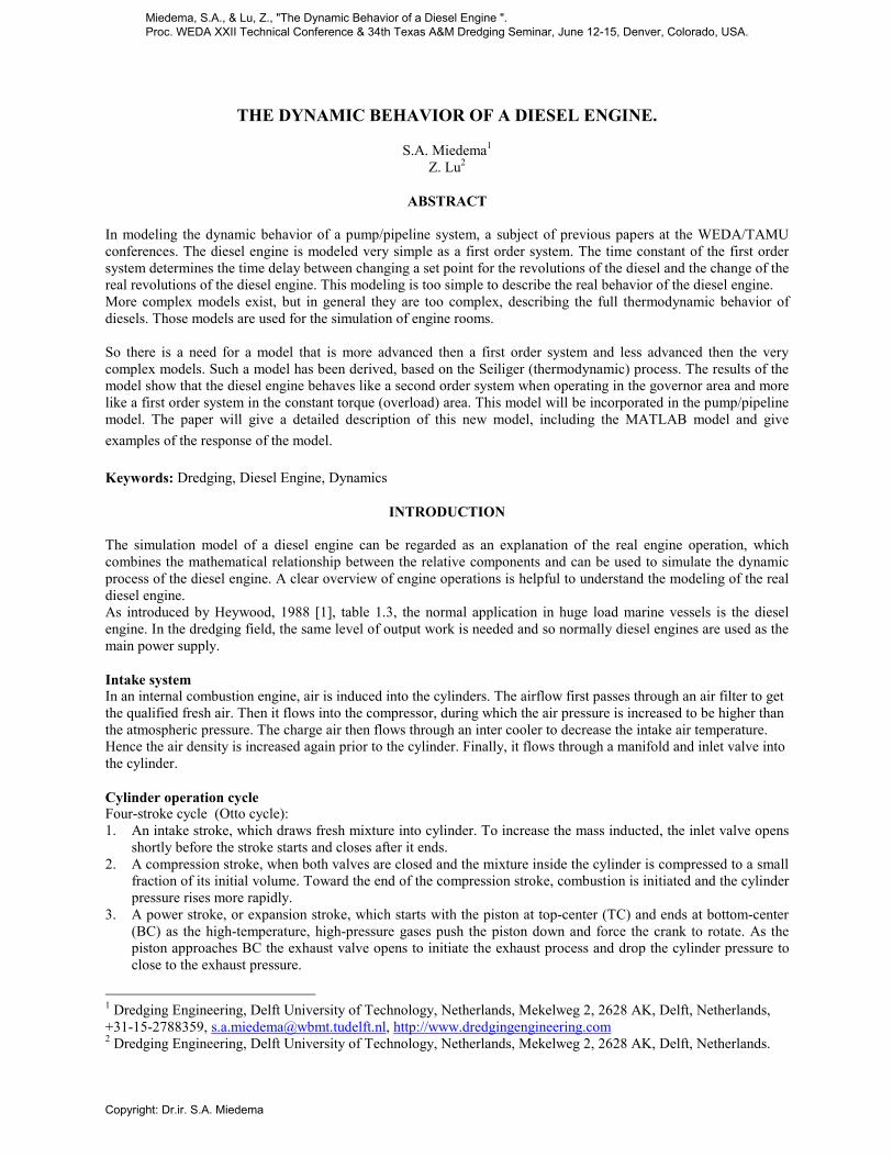
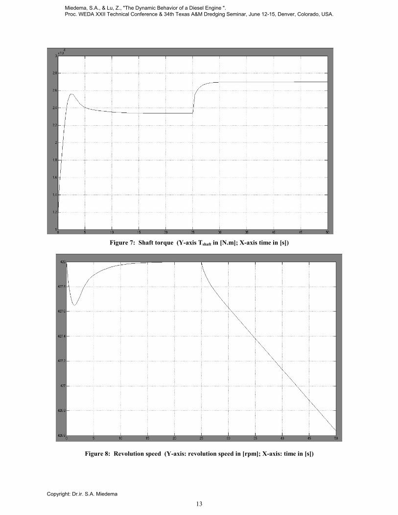
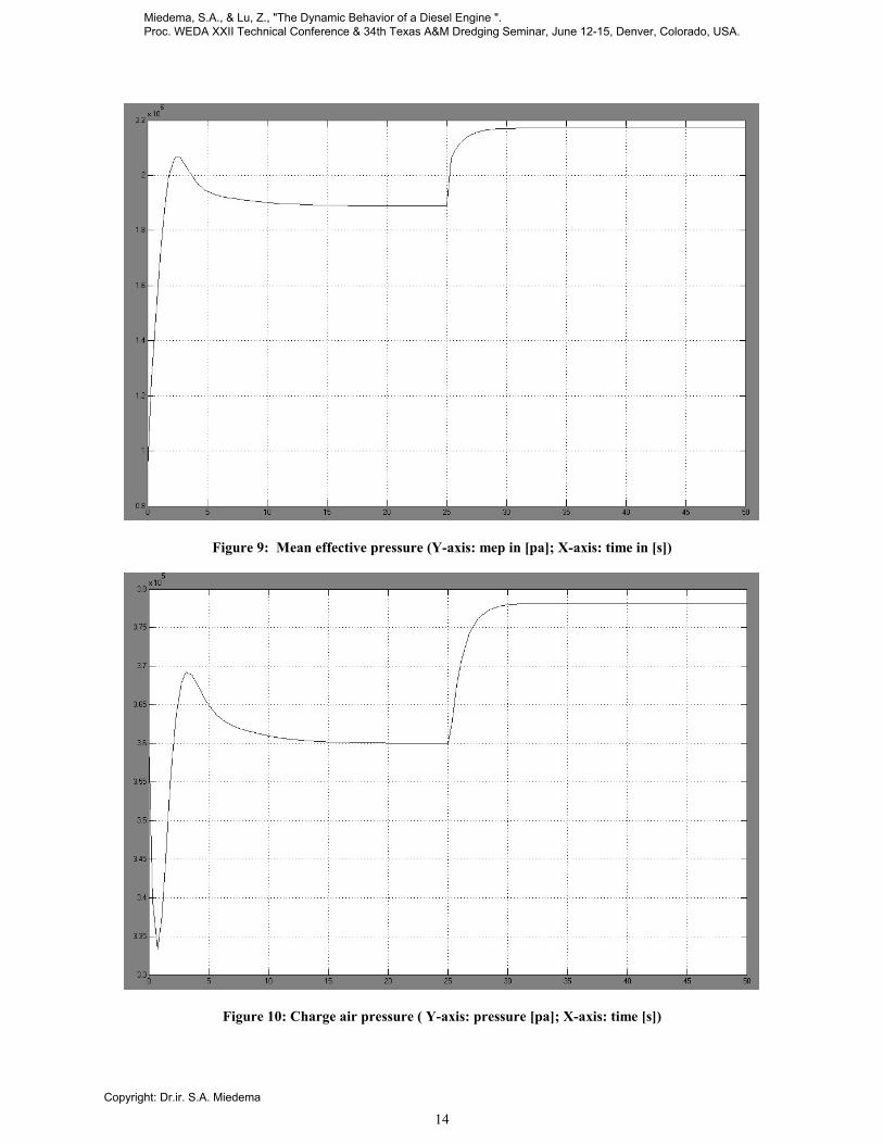
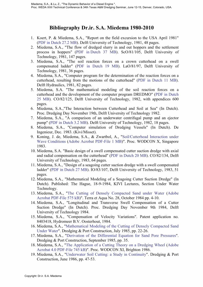
CONCLUSIONS In appendix I several output results of the simulations are shown in graphical form. The results are based on changing the pump load. Tpump is set as a step function: from 0 to 25 seconds, it equals to nominal value of shaft torque; at the time of 25th seconds it steps to 1.2 times the shaft torque. From the graphs, we may see that at the start point there is no output value of shaft torque, and thus the required torque is higher that torque offered by engine. The engine is decelerated and engine speed decreases. In the mean time the engine will ask for more fuel. The signal output from PI control is increased which increases the fuel injection. With more fuel, the torque of the shaft is increasing. After certain steps, the engine and pump system reach the balance point. All parameters are in stable point at that time. From the graph we may find the process is not simply a first-order action system, but it acts as a higher order system, due to the complicated thermodynamic processes and classic dynamic behavior of engine and turbine-compressor system and PI controller. At 25 seconds, as the required torque suddenly increases to 1.2 times the initial value, the engine will ask for more power again. Then the fuel injection, the shaft torque and the charging air pressure are increasing from stationary point. But this time as the required torque are too high, which leads to overload, not enough fuel is available, due to the limitation of the fuel management system. As the torque reaches the constant value of what is required by the pump, the engine speed decreases quickly. These graphs roughly show the behavior of a diesel engine with increased load. This behavior are nearby realistic condition. Later, if we apply this model with parameters from real facilities, such as real fuel pump and turbine and compressor etc, the graph will show the real situation more accurate. After the model is completed, it has been applied with data of a real M.A.N-L58/64 engine to check the reliability of work. With the manual of the M.A.N engine, not all the data required are available. So some estimations have to be made. Hence, the result may not show us the real operation the engine, but it shows the rough behavior of some important parameter in the dynamic process.
Miedema, S.A., & Lu, Z., "The Dynamic Behavior of a Diesel Engine ". Proc. WEDA XXII Technical Conference & 34th Texas A&M Dredging Seminar, June 12-15, Denver, Colorado, USA.
Copyright: Dr.ir. S.A. Miedema

11
SYMBOLS
a Constant specified for constant-volume process [-] b Constant specified for constant-pressure process [-] bsfc Specific fuel consumption [g/kwh] c Specific heat [kJ/kg.K] cp Specific heat at constant pressure [kJ/kg.K] cv Specific heat at constant volume [kJ/kg.K] H0 Heat value [kJ/kg] I Moment of inertial [kg.m2] k Specific heat ratio [-] m Mass [kg]
.m Mass flow rate [kg/s]
n Polytropic exponent [-] N Revolution speed in rpm [rpm] p Pressure [pa] q Heat transfer per unit mass fluid [kJ ] Q Heat transfer [kJ]
.Q Heat transfer rate [kJ/s]
R Gas constant [J/kg.k] r Compression ratio [-] T Time [s] T Temperature [K] T Torque [N.m] V Volume [m3] Vd Displaced cylinder volume [m3] W Work transfer [J] X Signal output of governor Xa Parameter for division of internal combustion process η Efficiency τ Characteristic time τid Ignition delay ω Revolution speed in Hz Φ Mass or energy flow
Miedema, S.A., & Lu, Z., "The Dynamic Behavior of a Diesel Engine ". Proc. WEDA XXII Technical Conference & 34th Texas A&M Dredging Seminar, June 12-15, Denver, Colorado, USA.
Copyright: Dr.ir. S.A. Miedema

12
SUBSCRIPTS
a Air atm Atmosphere c,comp Compressor cp Constant pressure process cv Constant volume process cyc Per cycle cyl Per cylinder eff Effective value eng Engine exh Exhaust f Fuel i Intake system kg Unit mass work fluid m mechanic Nom Nominal point characteristics pump Pump system q heat set Set point shaft Shaft characteristic T,turb Turbine tc Turbine-compressor system 1,2,3,4,5,6 Stage in cylinder process cycle
REFERENCES
[1] John B. Heywood; Internal Combustion Engine Fundamentals; McGraw-Hill Book Company 1988 [2] Hugo Grimmelius; Dave Boetius & Patrick Baan; The influence of sequential turbocharing control on
propulsion behavior; 12th SCSS 1999, The hague, The Netherlands [3] INTERNAL COMBUSTION ENGINES. London Academic Press 1988. [4] D.v.Duyn; Ontwikkelen en testen van een modulair simulatiemodel van een meervouding dieselmotor
gedreven pomp-leidingsysteem voor het simuleren van dynamisch gedrag; TU Delft, 1998. [5] Miedema, S.A., Modeling and Simulation of the Dynamic Behavior of a Pump/Pipeline System;
Meeting & Technical Conference of the Western Dredging Association. New Orleans, June 1996. [6] Michael J.Moran, Howard N.Shapiro; Fundamentals of Engineering Thermodynamics; John Wiley &
Sons,Inc, 1995 [7] Diesel Fuel Injection; BOSCH [8] Ir. S.E.M.de Bree; Centrifugal dredgpumps; MTI [9] Hugo Grimmelius; Intelligent condition monitoring for refrigeration plants based on process models,
model theory part. [10] N. Watson; M.S.Janota; Turbocharging the Internal Combustion Engine, The Macmillan press LTD,
1982 [11] V.I.Krutov; Automatic Control of Internal Combustion Engines; 1979
Miedema, S.A., & Lu, Z., "The Dynamic Behavior of a Diesel Engine ". Proc. WEDA XXII Technical Conference & 34th Texas A&M Dredging Seminar, June 12-15, Denver, Colorado, USA.
Copyright: Dr.ir. S.A. Miedema
13
Figure 7: Shaft torque (Y-axis Tshaft in [N.m]; X-axis time in [s])
Figure 8: Revolution speed (Y-axis: revolution speed in [rpm]; X-axis: time in [s])
Miedema, S.A., & Lu, Z., "The Dynamic Behavior of a Diesel Engine ". Proc. WEDA XXII Technical Conference & 34th Texas A&M Dredging Seminar, June 12-15, Denver, Colorado, USA.
Copyright: Dr.ir. S.A. Miedema
14
Figure 9: Mean effective pressure (Y-axis: mep in [pa]; X-axis: time in [s])
Figure 10: Charge air pressure ( Y-axis: pressure [pa]; X-axis: time [s])
Miedema, S.A., & Lu, Z., "The Dynamic Behavior of a Diesel Engine ". Proc. WEDA XXII Technical Conference & 34th Texas A&M Dredging Seminar, June 12-15, Denver, Colorado, USA.
Copyright: Dr.ir. S.A. Miedema

15
Figure 11: Signal output of governor (Y-axis: x [%]; X-axis: time [s])
Figure 12: Heat released from cylinder ( Y-axis: heat [kJ]; X-axis: time [s])
Miedema, S.A., & Lu, Z., "The Dynamic Behavior of a Diesel Engine ". Proc. WEDA XXII Technical Conference & 34th Texas A&M Dredging Seminar, June 12-15, Denver, Colorado, USA.
Copyright: Dr.ir. S.A. Miedema
Bibliography Dr.ir. S.A. Miedema 1980-2010
1. Koert, P. & Miedema, S.A., "Report on the field excursion to the USA April 1981" (PDF in Dutch 27.2 MB). Delft University of Technology, 1981, 48 pages.
2. Miedema, S.A., "The flow of dredged slurry in and out hoppers and the settlement process in hoppers" (PDF in Dutch 37 MB). ScO/81/105, Delft University of Technology, 1981, 147 pages.
3. Miedema, S.A., "The soil reaction forces on a crown cutterhead on a swell compensated ladder" (PDF in Dutch 19 MB). LaO/81/97, Delft University of Technology, 1981, 36 pages.
4. Miedema, S.A., "Computer program for the determination of the reaction forces on a cutterhead, resulting from the motions of the cutterhead" (PDF in Dutch 11 MB). Delft Hydraulics, 1981, 82 pages.
5. Miedema, S.A. "The mathematical modeling of the soil reaction forces on a cutterhead and the development of the computer program DREDMO" (PDF in Dutch 25 MB). CO/82/125, Delft University of Technology, 1982, with appendices 600 pages.
6. Miedema, S.A.,"The Interaction between Cutterhead and Soil at Sea" (In Dutch). Proc. Dredging Day November 19th, Delft University of Technology 1982.
7. Miedema, S.A., "A comparison of an underwater centrifugal pump and an ejector pump" (PDF in Dutch 3.2 MB). Delft University of Technology, 1982, 18 pages.
8. Miedema, S.A., "Computer simulation of Dredging Vessels" (In Dutch). De Ingenieur, Dec. 1983. (Kivi/Misset).
9. Koning, J. de, Miedema, S.A., & Zwartbol, A., "Soil/Cutterhead Interaction under Wave Conditions (Adobe Acrobat PDF-File 1 MB)". Proc. WODCON X, Singapore 1983.
10. Miedema, S.A. "Basic design of a swell compensated cutter suction dredge with axial and radial compensation on the cutterhead" (PDF in Dutch 20 MB). CO/82/134, Delft University of Technology, 1983, 64 pages.
11. Miedema, S.A., "Design of a seagoing cutter suction dredge with a swell compensated ladder" (PDF in Dutch 27 MB). IO/83/107, Delft University of Technology, 1983, 51 pages.
12. Miedema, S.A., "Mathematical Modeling of a Seagoing Cutter Suction Dredge" (In Dutch). Published: The Hague, 18-9-1984, KIVI Lectures, Section Under Water Technology.
13. Miedema, S.A., "The Cutting of Densely Compacted Sand under Water (Adobe Acrobat PDF-File 575 kB)". Terra et Aqua No. 28, October 1984 pp. 4-10.
14. Miedema, S.A., "Longitudinal and Transverse Swell Compensation of a Cutter Suction Dredge" (In Dutch). Proc. Dredging Day November 9th 1984, Delft University of Technology 1984.
15. Miedema, S.A., "Compensation of Velocity Variations". Patent application no. 8403418, Hydromeer B.V. Oosterhout, 1984.
16. Miedema, S.A., "Mathematical Modeling of the Cutting of Densely Compacted Sand Under Water". Dredging & Port Construction, July 1985, pp. 22-26.
17. Miedema, S.A., "Derivation of the Differential Equation for Sand Pore Pressures". Dredging & Port Construction, September 1985, pp. 35.
18. Miedema, S.A., "The Application of a Cutting Theory on a Dredging Wheel (Adobe Acrobat 4.0 PDF-File 745 kB)". Proc. WODCON XI, Brighton 1986.
19. Miedema, S.A., "Underwater Soil Cutting: a Study in Continuity". Dredging & Port Construction, June 1986, pp. 47-53.
Miedema, S.A., & Lu, Z., "The Dynamic Behavior of a Diesel Engine ". Proc. WEDA XXII Technical Conference & 34th Texas A&M Dredging Seminar, June 12-15, Denver, Colorado, USA.
Copyright: Dr.ir. S.A. Miedema

20. Miedema, S.A., "The cutting of water saturated sand, laboratory research" (In Dutch). Delft University of Technology, 1986, 17 pages.
21. Miedema, S.A., "The forces on a trenching wheel, a feasibility study" (In Dutch). Delft, 1986, 57 pages + software.
22. Miedema, S.A., "The translation and restructuring of the computer program DREDMO from ALGOL to FORTRAN" (In Dutch). Delft Hydraulics, 1986, 150 pages + software.
23. Miedema, S.A., "Calculation of the Cutting Forces when Cutting Water Saturated Sand (Adobe Acrobat 4.0 PDF-File 16 MB)". Basic Theory and Applications for 3-D Blade Movements and Periodically Varying Velocities for, in Dredging Commonly used Excavating Means. Ph.D. Thesis, Delft University of Technology, September 15th 1987.
24. Bakker, A. & Miedema, S.A., "The Specific Energy of the Dredging Process of a Grab Dredge". Delft University of Technology, 1988, 30 pages.
25. Miedema, S.A., "On the Cutting Forces in Saturated Sand of a Seagoing Cutter Suction Dredge (Adobe Acrobat 4.0 PDF-File 1.5 MB)". Proc. WODCON XII, Orlando, Florida, USA, April 1989. This paper was given the IADC Award for the best technical paper on the subject of dredging in 1989.
26. Miedema, S.A., "The development of equipment for the determination of the wear on pick-points" (In Dutch). Delft University of Technology, 1990, 30 pages (90.3.GV.2749, BAGT 462).
27. Miedema, S.A., "Excavating Bulk Materials" (In Dutch). Syllabus PATO course, 1989 & 1991, PATO The Hague, The Netherlands.
28. Miedema, S.A., "On the Cutting Forces in Saturated Sand of a Seagoing Cutter Suction Dredge (Adobe Acrobat 4.0 PDF-File 1.5 MB)". Terra et Aqua No. 41, December 1989, Elseviers Scientific Publishers.
29. Miedema, S.A., "New Developments of Cutting Theories with respect to Dredging, the Cutting of Clay (Adobe Acrobat 4.0 PDF-File 640 kB)". Proc. WODCON XIII, Bombay, India, 1992.
30. Davids, S.W. & Koning, J. de & Miedema, S.A. & Rosenbrand, W.F., "Encapsulation: A New Method for the Disposal of Contaminated Sediment, a Feasibility Study (Adobe Acrobat 4.0 PDF-File 3MB)". Proc. WODCON XIII, Bombay, India, 1992.
31. Miedema, S.A. & Journee, J.M.J. & Schuurmans, S., "On the Motions of a Seagoing Cutter Dredge, a Study in Continuity (Adobe Acrobat 4.0 PDF-File 396 kB)". Proc. WODCON XIII, Bombay, India, 1992.
32. Becker, S. & Miedema, S.A. & Jong, P.S. de & Wittekoek, S., "On the Closing Process of Clamshell Dredges in Water Saturated Sand (Adobe Acrobat 4.0 PDF-File 1 MB)". Proc. WODCON XIII, Bombay, India, 1992. This paper was given the IADC Award for the best technical paper on the subject of dredging in 1992.
33. Becker, S. & Miedema, S.A. & Jong, P.S. de & Wittekoek, S., "The Closing Process of Clamshell Dredges in Water Saturated Sand (Adobe Acrobat 4.0 PDF-File 1 MB)". Terra et Aqua No. 49, September 1992, IADC, The Hague.
34. Miedema, S.A., "Modeling and Simulation of Dredging Processes and Systems". Symposium "Zicht op Baggerprocessen", Delft University of Technology, Delft, The Netherlands, 29 October 1992.
35. Miedema, S.A., "Dredmo User Interface, Operators Manual". Report: 92.3.GV.2995. Delft University of Technology, 1992, 77 pages.
36. Miedema, S.A., "Inleiding Mechatronica, college WBM202" Delft University of Technology, 1992.
Miedema, S.A., & Lu, Z., "The Dynamic Behavior of a Diesel Engine ". Proc. WEDA XXII Technical Conference & 34th Texas A&M Dredging Seminar, June 12-15, Denver, Colorado, USA.
Copyright: Dr.ir. S.A. Miedema

37. Miedema, S.A. & Becker, S., "The Use of Modeling and Simulation in the Dredging Industry, in Particular the Closing Process of Clamshell Dredges", CEDA Dredging Days 1993, Amsterdam, Holland, 1993.
38. Miedema, S.A., "On the Snow-Plough Effect when Cutting Water Saturated Sand with Inclined Straight Blades (Adobe Acrobat 4.0 PDF-File 503 kB)". ASCE Proc. Dredging 94, Orlando, Florida, USA, November 1994. Additional Measurement Graphs. (Adobe Acrobat 4.0 PDF-File 209 kB).
39. Riet, E. van, Matousek, V. & Miedema, S.A., "A Reconstruction of and Sensitivity Analysis on the Wilson Model for Hydraulic Particle Transport (Adobe Acrobat 4.0 PDF-File 50 kB)". Proc. 8th Int. Conf. on Transport and Sedimentation of Solid Particles, 24-26 January 1995, Prague, Czech Republic.
40. Vlasblom, W.J. & Miedema, S.A., "A Theory for Determining Sedimentation and Overflow Losses in Hoppers (Adobe Acrobat 4.0 PDF-File 304 kB)". Proc. WODCON IV, November 1995, Amsterdam, The Netherlands 1995.
41. Miedema, S.A., "Production Estimation Based on Cutting Theories for Cutting Water Saturated Sand (Adobe Acrobat 4.0 PDF-File 423 kB)". Proc. WODCON IV, November 1995, Amsterdam, The Netherlands 1995. Additional Specific Energy and Production Graphs. (Adobe Acrobat 4.0 PDF-File 145 kB).
42. Riet, E.J. van, Matousek, V. & Miedema, S.A., "A Theoretical Description and Numerical Sensitivity Analysis on Wilson's Model for Hydraulic Transport in Pipelines (Adobe Acrobat 4.0 PDF-File 50 kB)". Journal of Hydrology & Hydromechanics, Slovak Ac. of Science, Bratislava, June 1996.
43. Miedema, S.A. & Vlasblom, W.J., "Theory for Hopper Sedimentation (Adobe Acrobat 4.0 PDF-File 304 kB)". 29th Annual Texas A&M Dredging Seminar. New Orleans, June 1996.
44. Miedema, S.A., "Modeling and Simulation of the Dynamic Behavior of a Pump/Pipeline System (Adobe Acrobat 4.0 PDF-File 318 kB)". 17th Annual Meeting & Technical Conference of the Western Dredging Association. New Orleans, June 1996.
45. Miedema, S.A., "Education of Mechanical Engineering, an Integral Vision". Faculty O.C.P., Delft University of Technology, 1997 (in Dutch).
46. Miedema, S.A., "Educational Policy and Implementation 1998-2003 (versions 1998, 1999 and 2000) (Adobe Acrobat 4.0 PDF_File 195 kB)". Faculty O.C.P., Delft University of Technology, 1998, 1999 and 2000 (in Dutch).
47. Keulen, H. van & Miedema, S.A. & Werff, K. van der, "Redesigning the curriculum of the first three years of the mechanical engineering curriculum". Proceedings of the International Seminar on Design in Engineering Education, SEFI-Document no.21, page 122, ISBN 2-87352-024-8, Editors: V. John & K. Lassithiotakis, Odense, 22-24 October 1998.
48. Miedema, S.A. & Klein Woud, H.K.W. & van Bemmel, N.J. & Nijveld, D., "Self Assesment Educational Programme Mechanical Engineering (Adobe Acrobat 4.0 PDF-File 400 kB)". Faculty O.C.P., Delft University of Technology, 1999.
49. Van Dijk, J.A. & Miedema, S.A. & Bout, G., "Curriculum Development Mechanical Engineering". MHO 5/CTU/DUT/Civil Engineering. Cantho University Vietnam, CICAT Delft, April 1999.
50. Miedema, S.A., "Considerations in building and using dredge simulators (Adobe Acrobat 4.0 PDF-File 296 kB)". Texas A&M 31st Annual Dredging Seminar. Louisville Kentucky, May 16-18, 1999.
Miedema, S.A., & Lu, Z., "The Dynamic Behavior of a Diesel Engine ". Proc. WEDA XXII Technical Conference & 34th Texas A&M Dredging Seminar, June 12-15, Denver, Colorado, USA.
Copyright: Dr.ir. S.A. Miedema

51. Miedema, S.A., "Considerations on limits of dredging processes (Adobe Acrobat 4.0 PDF-File 523 kB)". 19th Annual Meeting & Technical Conference of the Western Dredging Association. Louisville Kentucky, May 16-18, 1999.
52. Miedema, S.A. & Ruijtenbeek, M.G. v.d., "Quality management in reality", "Kwaliteitszorg in de praktijk". AKO conference on quality management in education. Delft University of Technology, November 3rd 1999.
53. Miedema, S.A., "Curriculum Development Mechanical Engineering (Adobe Acrobat 4.0 PDF-File 4 MB)". MHO 5-6/CTU/DUT. Cantho University Vietnam, CICAT Delft, Mission October 1999.
54. Vlasblom, W.J., Miedema, S.A., Ni, F., "Course Development on Topic 5: Dredging Technology, Dredging Equipment and Dredging Processes". Delft University of Technology and CICAT, Delft July 2000.
55. Miedema, S.A., Vlasblom, W.J., Bian, X., "Course Development on Topic 5: Dredging Technology, Power Drives, Instrumentation and Automation". Delft University of Technology and CICAT, Delft July 2000.
56. Randall, R. & Jong, P. de & Miedema, S.A., "Experience with cutter suction dredge simulator training (Adobe Acrobat 4.0 PDF-File 1.1 MB)". Texas A&M 32nd Annual Dredging Seminar. Warwick, Rhode Island, June 25-28, 2000.
57. Miedema, S.A., "The modelling of the swing winches of a cutter dredge in relation with simulators (Adobe Acrobat 4.0 PDF-File 814 kB)". Texas A&M 32nd Annual Dredging Seminar. Warwick, Rhode Island, June 25-28, 2000.
58. Hofstra, C. & Hemmen, A. van & Miedema, S.A. & Hulsteyn, J. van, "Describing the position of backhoe dredges (Adobe Acrobat 4.0 PDF-File 257 kB)". Texas A&M 32nd Annual Dredging Seminar. Warwick, Rhode Island, June 25-28, 2000.
59. Miedema, S.A., "Automation of a Cutter Dredge, Applied to the Dynamic Behaviour of a Pump/Pipeline System (Adobe Acrobat 4.0 PDF-File 254 kB)". Proc. WODCON VI, April 2001, Kuala Lumpur, Malaysia 2001.
60. Heggeler, O.W.J. ten, Vercruysse, P.M., Miedema, S.A., "On the Motions of Suction Pipe Constructions a Dynamic Analysis (Adobe Acrobat 4.0 PDF-File 110 kB)". Proc. WODCON VI, April 2001, Kuala Lumpur, Malaysia 2001.
61. Miedema, S.A. & Zhao Yi, "An Analytical Method of Pore Pressure Calculations when Cutting Water Saturated Sand (Adobe Acrobat PDF-File 2.2 MB)". Texas A&M 33nd Annual Dredging Seminar, June 2001, Houston, USA 2001.
62. Miedema, S.A., "A Numerical Method of Calculating the Dynamic Behaviour of Hydraulic Transport (Adobe Acrobat PDF-File 246 kB)". 21st Annual Meeting & Technical Conference of the Western Dredging Association, June 2001, Houston, USA 2001.
63. Zhao Yi, & Miedema, S.A., "Finite Element Calculations To Determine The Pore Pressures When Cutting Water Saturated Sand At Large Cutting Angles (Adobe Acrobat PDF-File 4.8 MB)". CEDA Dredging Day 2001, November 2001, Amsterdam, The Netherlands.
64. Miedema, S.A., "Mission Report Cantho University". MHO5/6, Phase Two, Mission to Vietnam by Dr.ir. S.A. Miedema DUT/OCP Project Supervisor, 27 September-8 October 2001, Delft University/CICAT.
65. (Zhao Yi), & (Miedema, S.A.), "
" (Finite Element Calculations To Determine The Pore Pressures When Cutting Water
Miedema, S.A., & Lu, Z., "The Dynamic Behavior of a Diesel Engine ". Proc. WEDA XXII Technical Conference & 34th Texas A&M Dredging Seminar, June 12-15, Denver, Colorado, USA.
Copyright: Dr.ir. S.A. Miedema

Saturated Sand At Large Cutting Angles (Adobe Acrobat PDF-File 4.8 MB))". To be published in 2002.
66. Miedema, S.A., & Riet, E.J. van, & Matousek, V., "Theoretical Description And Numerical Sensitivity Analysis On Wilson Model For Hydraulic Transport Of Solids In Pipelines (Adobe Acrobat PDF-File 147 kB)". WEDA Journal of Dredging Engineering, March 2002.
67. Miedema, S.A., & Ma, Y., "The Cutting of Water Saturated Sand at Large Cutting Angles (Adobe Acrobat PDF-File 3.6 MB)". Proc. Dredging02, May 5-8, Orlando, Florida, USA.
68. Miedema, S.A., & Lu, Z., "The Dynamic Behavior of a Diesel Engine (Adobe Acrobat PDF-File 363 kB)". Proc. WEDA XXII Technical Conference & 34th Texas A&M Dredging Seminar, June 12-15, Denver, Colorado, USA.
69. Miedema, S.A., & He, Y., "The Existance of Kinematic Wedges at Large Cutting Angles (Adobe Acrobat PDF-File 4 MB)". Proc. WEDA XXII Technical Conference & 34th Texas A&M Dredging Seminar, June 12-15, Denver, Colorado, USA.
70. Ma, Y., Vlasblom, W.J., Miedema, S.A., Matousek, V., "Measurement of Density and Velocity in Hydraulic Transport using Tomography". Dredging Days 2002, Dredging without boundaries, Casablanca, Morocco, V64-V73, 22-24 October 2002.
71. Ma, Y., Miedema, S.A., Vlasblom, W.J., "Theoretical Simulation of the Measurements Process of Electrical Impedance Tomography". Asian Simulation Conference/5th International Conference on System Simulation and Scientific Computing, Shanghai, 3-6 November 2002, p. 261-265, ISBN 7-5062-5571-5/TP.75.
72. Thanh, N.Q., & Miedema, S.A., "Automotive Electricity and Electronics". Delft University of Technology and CICAT, Delft December 2002.
73. Miedema, S.A., Willemse, H.R., "Report on MHO5/6 Mission to Vietnam". Delft University of Technology and CICAT, Delft Januari 2003.
74. Ma, Y., Miedema, S.A., Matousek, V., Vlasblom, W.J., "Tomography as a Measurement Method for Density and Velocity Distributions". 23rd WEDA Technical Conference & 35th TAMU Dredging Seminar, Chicago, USA, june 2003.
75. Miedema, S.A., Lu, Z., Matousek, V., "Numerical Simulation of a Development of a Density Wave in a Long Slurry Pipeline". 23rd WEDA Technical Conference & 35th TAMU Dredging Seminar, Chicago, USA, june 2003.
76. Miedema, S.A., Lu, Z., Matousek, V., "Numerical simulation of the development of density waves in a long pipeline and the dynamic system behavior". Terra et Aqua, No. 93, p. 11-23.
77. Miedema, S.A., Frijters, D., "The Mechanism of Kinematic Wedges at Large Cutting Angles - Velocity and Friction Measurements". 23rd WEDA Technical Conference & 35th TAMU Dredging Seminar, Chicago, USA, june 2003.
78. Tri, Nguyen Van, Miedema, S.A., Heijer, J. den, "Machine Manufacturing Technology". Lecture notes, Delft University of Technology, Cicat and Cantho University Vietnam, August 2003.
79. Miedema, S.A., "MHO5/6 Phase Two Mission Report". Report on a mission to Cantho University Vietnam October 2003. Delft University of Technology and CICAT, November 2003.
80. Zwanenburg, M., Holstein, J.D., Miedema, S.A., Vlasblom, W.J., "The Exploitation of Cockle Shells". CEDA Dredging Days 2003, Amsterdam, The Netherlands, November 2003.
81. Zhi, L., Miedema, S.A., Vlasblom, W.J., Verheul, C.H., "Modeling and Simulation of the Dynamic Behaviour of TSHD's Suction Pipe System by using Adams". CHIDA Dredging Days, Shanghai, China, november 2003.
Miedema, S.A., & Lu, Z., "The Dynamic Behavior of a Diesel Engine ". Proc. WEDA XXII Technical Conference & 34th Texas A&M Dredging Seminar, June 12-15, Denver, Colorado, USA.
Copyright: Dr.ir. S.A. Miedema

82. Miedema, S.A., "The Existence of Kinematic Wedges at Large Cutting Angles". CHIDA Dredging Days, Shanghai, China, november 2003.
83. Miedema, S.A., Lu, Z., Matousek, V., "Numerical Simulation of the Development of Density Waves in a Long Pipeline and the Dynamic System Behaviour". Terra et Aqua 93, December 2003.
84. Miedema, S.A. & Frijters, D.D.J., "The wedge mechanism for cutting of water saturated sand at large cutting angles". WODCON XVII, September 2004, Hamburg Germany.
85. Verheul, O. & Vercruijsse, P.M. & Miedema, S.A., "The development of a concept for accurate and efficient dredging at great water depths". WODCON XVII, September 2004, Hamburg Germany.
86. Miedema, S.A., "THE CUTTING MECHANISMS OF WATER SATURATED SAND AT SMALL AND LARGE CUTTING ANGLES". International Conference on Coastal Infrastructure Development - Challenges in the 21st Century. HongKong, november 2004.
87. Ir. M. Zwanenburg , Dr. Ir. S.A. Miedema , Ir J.D. Holstein , Prof.ir. W.J.Vlasblom, "REDUCING THE DAMAGE TO THE SEA FLOOR WHEN DREDGING COCKLE SHELLS". WEDAXXIV & TAMU36, Orlando, Florida, USA, July 2004.
88. Verheul, O. & Vercruijsse, P.M. & Miedema, S.A., "A new concept for accurate and efficient dredging in deep water". Ports & Dredging, IHC, 2005, E163.
89. Miedema, S.A., "Scrapped?". Dredging & Port Construction, September 2005. 90. Miedema, S.A. & Vlasblom, W.J., " Bureaustudie Overvloeiverliezen". In opdracht
van Havenbedrijf Rotterdam, September 2005, Confidential. 91. He, J., Miedema, S.A. & Vlasblom, W.J., "FEM Analyses Of Cutting Of Anisotropic
Densely Compacted and Saturated Sand", WEDAXXV & TAMU37, New Orleans, USA, June 2005.
92. Miedema, S.A., "The Cutting of Water Saturated Sand, the FINAL Solution". WEDAXXV & TAMU37, New Orleans, USA, June 2005.
93. Miedema, S.A. & Massie, W., "Selfassesment MSc Offshore Engineering", Delft University of Technology, October 2005.
94. Miedema, S.A., "THE CUTTING OF WATER SATURATED SAND, THE SOLUTION". CEDA African Section: Dredging Days 2006 - Protection of the coastline, dredging sustainable development, Nov. 1-3, Tangiers, Morocco.
95. Miedema, S.A., "La solution de prélèvement par désagrégation du sable saturé en eau". CEDA African Section: Dredging Days 2006 - Protection of the coastline, dredging sustainable development, Nov. 1-3, Tangiers, Morocco.
96. Miedema, S.A. & Vlasblom, W.J., "THE CLOSING PROCESS OF CLAMSHELL DREDGES IN WATER-SATURATED SAND". CEDA African Section: Dredging Days 2006 - Protection of the coastline, dredging sustainable development, Nov. 1-3, Tangiers, Morocco.
97. Miedema, S.A. & Vlasblom, W.J., "Le processus de fermeture des dragues à benne preneuse en sable saturé". CEDA African Section: Dredging Days 2006 - Protection of the coastline, dredging sustainable development, Nov. 1-3, Tangiers, Morocco.
98. Miedema, S.A. "THE CUTTING OF WATER SATURATED SAND, THE SOLUTION". The 2nd China Dredging Association International Conference & Exhibition, themed 'Dredging and Sustainable Development' and in Guangzhou, China, May 17-18 2006.
99. Ma, Y, Ni, F. & Miedema, S.A., "Calculation of the Blade Cutting Force for small Cutting Angles based on MATLAB". The 2nd China Dredging Association
Miedema, S.A., & Lu, Z., "The Dynamic Behavior of a Diesel Engine ". Proc. WEDA XXII Technical Conference & 34th Texas A&M Dredging Seminar, June 12-15, Denver, Colorado, USA.
Copyright: Dr.ir. S.A. Miedema

International Conference & Exhibition, themed 'Dredging and Sustainable Development' and in Guangzhou, China, May 17-18 2006.
100. ,"" (download). The 2nd China Dredging
Association International Conference & Exhibition, themed 'Dredging and Sustainable Development' and in Guangzhou, China, May 17-18 2006.
101. Miedema, S.A. , Kerkvliet, J., Strijbis, D., Jonkman, B., Hatert, M. v/d, "THE DIGGING AND HOLDING CAPACITY OF ANCHORS". WEDA XXVI AND TAMU 38, San Diego, California, June 25-28, 2006.
102. Schols, V., Klaver, Th., Pettitt, M., Ubuan, Chr., Miedema, S.A., Hemmes, K. & Vlasblom, W.J., "A FEASIBILITY STUDY ON THE APPLICATION OF FUEL CELLS IN OIL AND GAS SURFACE PRODUCTION FACILITIES". Proceedings of FUELCELL2006, The 4th International Conference on FUEL CELL SCIENCE, ENGINEERING and TECHNOLOGY, June 19-21, 2006, Irvine, CA.
103. Miedema, S.A., "Polytechnisch Zakboek 51ste druk, Hoofdstuk G: Werktuigbouwkunde", pG1-G88, Reed Business Information, ISBN-10: 90.6228.613.5, ISBN-13: 978.90.6228.613.3. Redactie: Fortuin, J.B., van Herwijnen, F., Leijendeckers, P.H.H., de Roeck, G. & Schwippert, G.A.
104. MA Ya-sheng, NI Fu-sheng, S.A. Miedema, "Mechanical Model of Water Saturated Sand Cutting at Blade Large Cutting Angles", Journal of Hohai University Changzhou, ISSN 1009-1130, CN 32-1591, 2006. 绞刀片大角度切削水饱和沙的力学模型, 马亚生[1] 倪福生[1] S.A.Miedema[2], 《河海大学常州分校学报》-2006年20卷3期 -59-61页
105. Miedema, S.A., Lager, G.H.G., Kerkvliet, J., “An Overview of Drag Embedded Anchor Holding Capacity for Dredging and Offshore Applications”. WODCON, Orlando, USA, 2007.
106. Miedema, S.A., Rhee, C. van, “A SENSITIVITY ANALYSIS ON THE EFFECTS OF DIMENSIONS AND GEOMETRY OF TRAILING SUCTION HOPPER DREDGES”. WODCON ORLANDO, USA, 2007.
107. Miedema, S.A., Bookreview: Useless arithmetic, why environmental scientists can't predict the future, by Orrin H. Pilkey & Linda Pilkey-Jarvis. Terra et Aqua 108, September 2007, IADC, The Hague, Netherlands.
108. Miedema, S.A., Bookreview: The rock manual: The use of rock in hydraulic engineering, by CIRIA, CUR, CETMEF. Terra et Aqua 110, March 2008, IADC, The Hague, Netherlands.
109. Miedema, S.A., "An Analytical Method To Determine Scour". WEDA XXVIII & Texas A&M 39. St. Louis, USA, June 8-11, 2008.
110. Miedema, S.A., "A Sensitivity Analysis Of The Production Of Clamshells". WEDA XXVIII & Texas A&M 39. St. Louis, USA, June 8-11, 2008.
111. Miedema, S.A., "An Analytical Approach To The Sedimentation Process In Trailing Suction Hopper Dredgers". Terra et Aqua 112, September 2008, IADC, The Hague, Netherlands.
112. Hofstra, C.F., & Rhee, C. van, & Miedema, S.A. & Talmon, A.M., "On The Particle Trajectories In Dredge Pump Impellers". 14th International Conference Transport & Sedimentation Of Solid Particles. June 23-27 2008, St. Petersburg, Russia.
113. Miedema, S.A., "A Sensitivity Analysis Of The Production Of Clamshells". WEDA Journal of Dredging Engineering, December 2008.
Miedema, S.A., & Lu, Z., "The Dynamic Behavior of a Diesel Engine ". Proc. WEDA XXII Technical Conference & 34th Texas A&M Dredging Seminar, June 12-15, Denver, Colorado, USA.
Copyright: Dr.ir. S.A. Miedema

114. Miedema, S.A., "New Developments Of Cutting Theories With Respect To Dredging, The Cutting Of Clay And Rock". WEDA XXIX & Texas A&M 40. Phoenix Arizona, USA, June 14-17 2009.
115. Miedema, S.A., "A Sensitivity Analysis Of The Scaling Of TSHD's". WEDA XXIX & Texas A&M 40. Phoenix Arizona, USA, June 14-17 2009.
116. Liu, Z., Ni, F., Miedema, S.A., “Optimized design method for TSHD’s swell compensator, basing on modelling and simulation”. International Conference on Industrial Mechatronics and Automation, pp. 48-52. Chengdu, China, May 15-16, 2009.
117. Miedema, S.A., "The effect of the bed rise velocity on the sedimentation process in hopper dredges". Journal of Dredging Engineering, Vol. 10, No. 1 , 10-31, 2009.
118. Miedema, S.A., “New developments of cutting theories with respect to offshore applications, the cutting of sand, clay and rock”. ISOPE 2010, Beijing China, June 2010.
119. Miedema, S.A., “The influence of the strain rate on cutting processes”. ISOPE 2010, Beijing China, June 2010.
120. Ramsdell, R.C., Miedema, S.A., “Hydraulic transport of sand/shell mixtures”. WODCON XIX, Beijing China, September 2010.
121. Abdeli, M., Miedema, S.A., Schott, D., Alvarez Grima, M., “The application of discrete element modeling in dredging”. WODCON XIX, Beijing China, September 2010.
122. Hofstra, C.F., Miedema, S.A., Rhee, C. van, “Particle trajectories near impeller blades in centrifugal pumps. WODCON XIX, Beijing China, September 2010.
123. Miedema, S.A., “Constructing the Shields curve, a new theoretical approach and its applications”. WODCON XIX, Beijing China, September 2010.
124. Miedema, S.A., “The effect of the bed rise velocity on the sedimentation process in hopper dredges”. WODCON XIX, Beijing China, September 2010.
Miedema, S.A., & Lu, Z., "The Dynamic Behavior of a Diesel Engine ". Proc. WEDA XXII Technical Conference & 34th Texas A&M Dredging Seminar, June 12-15, Denver, Colorado, USA.
Copyright: Dr.ir. S.A. Miedema