the downtown family ymca downtown family ymca will mark the comeback of a familiar neighborhood icon...
TRANSCRIPT

The Downtown Family YMCA
Detroit, MI
Alvaro Zumaran The Pennsylvania State University
Department of Architectural Engineering Construction Management
Technical Report 1 October 5, 2005
Table of Contents
Executive Summary………………………………………………..Page 1
Building Systems Summary……………………………………….Page 2
Project Cost Evaluation……………………………………………Page 3
Local Conditions…………………………………………………...Page 3-4
Client Information…………………………………………………..Page 4-5
Project Delivery System……………………………………………Page 5-7
Staffing Plan………………………………………………………..Page 8 Appendices
Appendix A – Project Cost Evaluation Data
Appendix B – Project Schedule Summary
Appendix C – Site Plan of Existing Conditions

Executive Summary
It has been over 90 years since Detroit has had a YMCA to call its own. The Downtown Family YMCA will mark the comeback of a familiar neighborhood icon that Detroit has been missing for nearly a century. This is a project that the citizens of Detroit (as well as surrounding counties) have been monitoring and anxiously waiting for. Its unique design and fresh look is just what Detroit needs in its mission to rejuvenate the city The architects/engineers for this job are SmithGroup and the construction manager is Barton Malow Co. The project commenced in December of 2003 and the goal is to have the building ready by December 2005. Like any construction project, set-backs are inevitable. However, having great management in all the entities has kept this project running smoothly, and it appears the completion date will be reached. This report was produced to give the reader a general overview of the key and general aspects of this project. Illustrations and in-depth descriptions are provided to give the person who reads this report more of a personal feel regarding the processes that are involved with this project. Amongst the contents of this report, one will find all of the following: Site plans showing the location of the project along with existing conditions on that particular site. The local conditions of the site, which includes the preferred methods of construction in the Detroit-metro area, will also be analyzed. Furthermore, there will also be information on the owner of the project; we will take a look at a brief biographical sketch and discuss the goals of the owner. The details of this project’s delivery system will also be discussed, as well as illustrations demonstrating the structure of the key players. Lastly, the staffing plan of the construction managers will be shown and evaluated. Furthermore, I have also included documents that I have produced myself as well as documents that Barton Malow Co. and SmithGroup have provided me with that will help the reader better comprehend the schedule, cost and building systems aspect of the project.
1

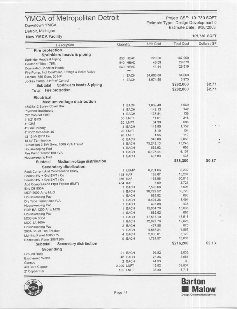
BUILDING SYSTEMS SUMMARY Demolition This project is being built over an existing parking lot. When performing the site conditions evaluation, there were remnants of a foundation and pieces of concrete throughout the site. This did not interfere with the process of excavation Structural Frame An 80 ton crane was used for the heavier members. Only one crane was used due to the space limitations of the site. There are different spans of beams used for the office areas, open gym areas and especially the theatre. Most of the connections are bolted, but in areas such as the elevated track overlooking the basketball court, there were also full penetration welds. Besides this, the atrium/lobby level has a climbing wall that utilizes cross bracing for support. Steel floor framing is being used with shear studs at 1 per 48” on a 4,000 psi Lightweight slab on deck. No composite beams are used. Building Envelope The building envelope consists of decorative CMU and glass panels. The CMU areas are cavity walls for load bearing purposes. The glass façade was installed using a curtain wall system to allow for maximum visibility both inside and out. Mechanical Hot water heating generation is used. 2 Firetube boilers at 3200 MBH are installed for this. Med-press, HHW/DX “Intellipak” rooftop air handling units is being used. Both regular and fan-powered VAV boxes with reheat are being used for the circulation of air. Upon observation of the ductwork, one will see that there is a lot of inconsistency to it. What I mean by this is that; due to the half levels, the ductwork is forced to climb up a level at one part of the building then it has to drop again to accommodate another part of the building. Electrical The electrical system in this building mainly consists of a medium voltage distribution system along with a secondary distribution. The main transformer of this building is 1500kVA at 480/277V Y - 3Φ. In addition to this, there is a substation at 3-5kV and 1,000kVA transfer (medium dist.) and a MDP 2000 Amp MLO (secondary dist.). In order to provide all the lighting in the building with the appropriate amount of power, (4) 480/277V panels are used along with (9) 208/120V receptacle panels.
2

PROJECT COST EVALUATION (See attached sheets in Appendix A) Actual total construction cost - $25,795,000 Actual adjusted total cost - $29,000,000 Actual cost per SF - $285.07 D4 total building cost - $18,551,164 D4 adjusted total cost - $22,070,554 (Includes site work) D4 cost per SF - $216.95 RS Means total project cost per Square Foot (3/4 end) - $178.50/SF (Includes mechanical and electrical work) RS Means total project cost – $18,158,805 To my surprise the cost estimate that I generated with the D4 software did not stray far from the actual project costs. The difference was over $5 million, but I expected D4 to go way over or way under (~$10 million). The price difference was not too much of a surprise at second glance. After all, the project that I modeled the estimate after is also in Michigan, it took place 2 years earlier, and it is also a recreation center. Besides this, the design fee, money for furniture and the preconstruction/utilities relocation are some costs that D4, to my knowledge, has not included. Looking closer at the RS Means estimate, I began to wonder if the estimate that I calculated using the RS Means data included the price of the natatorium, elevated track, and the theatre. LOCAL CONDITIONS Preferred Methods of Construction In the Detroit metro area, using concrete for buildings is not as preferred as using steel. The main reason for this preference deals with availability of concrete. There are no close or local concrete companies, which makes production and transportation more expensive. Due to this, there is a steel building preference because steel is so much easier to acquire. Availability for Construction Parking If any construction is to take place in downtown Detroit, workers usually have to find parking on their own. They usually park in parking decks. The reason for this being that there is not enough free space in downtown to provide parking for all the employees on any particular site. Soil/Subsurface Water Condition The soil conditions encountered at the soil boring locations appeared consistent with the boring previously performed at the project site. The soil profile generally consists of sand and clay fill near the surface, overlying low plasticity soft to hard natural silty clays. Beneath the silty clays, dense silty sandy clay (hardpan) was encountered, to the explored
3

depths of the soil borings. The following gives a generalized summary description of the soils encountered in the current borings performed at the subject site, beginning at the ground surface and proceeding downward: Stratum 1: Asphaltic and Portland cement concrete and base material. Two to six inches of Asphaltic concrete overlying 5 to 9 inches of crushed slag base material reported at five of the current soil boring locations. Stratum 2: Various fill materials. At the most recent borings, sand and clay fill with varying amounts of construction debris, was encountered beneath stratum 1 materials, extending to depths of 5.5 to 17 feet. Brick and concrete fill, including possible concrete slabs, were encountered at several of the boring locations. Stratum 3: Natural silty/sandy clays: 119-121 feet. However, the clays in the upper 20 and 30 feet were hard to stiff. Natural medium dense sands and sandy silts were encountered beneath the fill materials at boring B6, extending to a depth of 16 feet. A single N-value of 29 bpf was obtained in these materials Stratum 4: Clay hardpan. Dense silty sandy clays (hardpan soils) were encountered beneath the Stratum 3 clays, extending to the explored depths of the soil borings. Due to wash rotary drilling methods used to advance the deeper soil borings, groundwater levels upon completion of the current borings are not available for the deep soil borings; however, groundwater was encountered at depths of 19.5 to 13 feet during drilling operations, and at a depth of 36 feet below the ground surface upon completion of drilling operations at boring B6. The groundwater levels should be anticipated to fluctuate throughout the year due to variations in precipitation, evaporation, surface runoff and certain construction activities. CLIENT INFORMATION Owner’s Representative The client of this project is the metro Detroit YMCA. The client’s representative is Mrs. Lorie Uranga. Mrs. Uranga has spent the last 16 years dealing with construction. She has been with the YMCA for the past seven years. This project will be Mrs. Uranga’s 3rd new construction building for the YMCA. She completed one in Milford, MI in 2000 and another in Auburn Hills, MI in 2002. She is responsible for all property management. Why Are They Building This Facility? The main reason for building a YMCA in downtown Detroit is because there hasn’t been one there in almost 90 years, so this is would be a ‘revival mission.’ Cost, Quality, Schedule and Safety Expectations In terms of cost expectations, they do not want the cost of the building to exceed the $29 million budget. However, there are donors and contributors that generously give money, but they want their money going towards something aesthetic and that recognizes the donor/contributor. One good example of this is the fountain that will be placed outside by the main entrance. One of the big quality/design goals of the YMCA, which can be seen by the design, is to promote high visibility. The want the building to glow at night, that is why there is so
4

much glass used. The use of glass also gives people a chance to see what is going on from the inside out and vice-versa. The concept of the ‘half-levels’ is also supposed to promote this visibility issue as well as inspiring high energy. As for schedule expectations both Mrs. Uranga and Mr. Luedeman (project manager with Barton Malow) are collaboratively working hard to reach the goal of the occupancy date (December 2005). There have been processes all over the schedule that have needed to speed up, this usually means that contractors either have to put in longer hours and/or progress on work during the weekend. Safety expectations are high for both the YMCA and Barton Malow. Safety issues have been especially strict on this site ever since an incident that occurred this past summer. Safety inspectors from MIOSHA came to examine the site and found that there were some people working at dangerous heights without being tied-off. This was the biggest issue that they found on the site, and needless to say, it produced some hefty fines. Besides being concerned with the safety of their workers, the heavy consequences that come with a situation like this is something that the YMCA and Barton Malow cannot afford. Joint, Dual, or Phased Occupancy RequirementsThere are no other tenants in this building. The building is strictly for the YMCA and its members. However, there is a pick-up station for the ‘people-mover’ on the same site. This station is right outside of the building and it will not be relocated. This station will not be relocated due to the fact that it is a main pick-up point, and also because it will allow members to get dropped off right in front of the Y if they are all the way across town. Completing Project to Owner’s Satisfaction The main issue that Mrs. Uranga stated is that the project be completed on time. It is very important that they open on the scheduled date to begin welcoming members. Furthermore, the aesthetics of the building must be to the liking of the other members of the metro Detroit YMCA panel as well as the contributors who have donated so much to make this building a reality. PROJECT DELIVERY SYSTEM The project started out with Barton Malow Company acting as a construction manager. Once all the subcontracts were awarded, a GMP (Guaranteed Maximum Price) was established and the contract changed to a CM at risk. The CM approach was chosen mainly because of past relationships. Ben Maibach III, President of Barton Malow, is one of the head board members on the YMCA committee and he has been thinking of getting involved with this project for the last 5 years. So, seeing as how Barton Malow already has a direct connection with the YMCA and they are a construction management company, a decision was easily reached.
5

Organizational Chart of Major Project Players
YMCA (Owner)
SmithGroup (Architects/ Engineers)
Barton Malow (Construction
Managers)
Consultants
List of contacts ▫ YMCA: Lorie Uranga – [email protected] (313) 267-5300 ▫ SmithGroup: Kevin Shultis – [email protected] (313) 442-8318 ▫ Barton Malow: Loren Luedeman – [email protected] (313) 963-4175 ▫ John E. Green Co.: Mark Jones – (313) 868-2400 ▫ Detroit Electrical Services, LLC: Grace Tache – (313) 223-2800 ▫ Oakland Plumbing: Mike Scott – (586) 731-3535 Contractual Agreements The contracts held with the subs reflected just about all the same requirements that Barton Malow was held to with the owner minus the CM part of things. The subcontract was GC/guaranteed maximum price contract. In essence the contract stated that the sub has to complete their scope of work for the contract price and by the scheduled completion dates. Also, they must complete their work without interfering with the other trades work (make it so that another trade cannot complete their work by the scheduled completion date). Contractor Selection In terms of how a contractor is selected; in Detroit, all public jobs require a certain percentage of minority owned companies and women-owned businesses be involved in projects. Since the YMCA wasn’t a considered a public job, they didn’t have to follow
American Society of Theatre Consultants
(Theatre)
Water Tech Inc.
(Natatorium)
John E. Green Co.
(Mechanical)
Detroit Electrical
Services, LLC
GMP
GMP
GMP
Fee
Oakland Plumbing
Major Contractors
6

this rule of having a certain percentage, but they did it anyway to demonstrate good deed. After the YMCA confirmed that they wanted a percentage of minority and woman-owned businesses, Barton Malow prepared a bid list and the YMCA went on to approve it. Bonds and Insurance Performance and payment bonds were needed for this job in order for a contractor to commence work. In terms of insurance, each contractor was required to have the following: -commercial general liability -automotive liability -umbrella/excess -worker’s compensation -employer’s liability Contract Types and Delivery System Analysis I believe that even though there weren’t different types of contracts used amongst the major players, keeping it simple was the best way to go. I definitely believe that by limiting the variety, simplicity was maintained. This is especially true since the budget was a very critical issue for this project. In terms of the project delivery method, I thought it was interesting how Barton Malow went from a construction manager to construction manager at risk – after the subcontracts were awarded. I believe that the delivery method is working out well, but I would like to have seen how a Design-Build method would have worked out for this project. I say this mainly because I know that the D-B method provides faster project delivery (to ensure the occupancy date), a fixed cost – lump sum contract (ensuring price predictability), and more competitive prices from the contractors. Besides this, I think it would have been interesting to see what value engineering concepts would have been implemented.
7

STAFFING PLAN
Project Director John Steinhebel
Project Engineer Sachrissa Suthers
Superintendent Scott Lane
Project Manager Loren Luedeman
Field Engineer Dimitrius Ebry
Superintendent Dion Simmons
Co-manage
The Barton Malow staffing structure is traditionally simple. As you can see on the flowchart, Mr. John Steinheble is the Project Director for the YMCA project and everyone else falls under him. Something that is a little less traditional can be seen in the second row: Scott Lane, a superintendent, is co-managing the job with the project manager, Loren Luedeman. Even though Mr. Lane’s official title on this job is as a superintendent, he takes on some project manager duties to help Mr. Luedeman with the progress of the job. Dion Simmons is the only person underneath Mr. Lane; while Mr. Luedeman has a project engineer (Mrs. Suthers) and field engineer (Mr. Ebry) that report directly to him.
8


Downtown Family YMCACase Number AGZ103Project Name Downtown Family YMCAProject Cost 18551164Site Size 746183Building Use RecreationalBid Date 8/15/2001Num Floors 4Read Only FalseHistoric FalseBase Month DecBase Year 2003Base Location MI - DetroitProjected Month DecProjected Year 2003Projected Location MI - DetroitBuilding Size 110000Auto Calc TrueNum Buildings 1Project Height 401st Floor Height 101st Floor Size 27500Foundation CONExterior Wall CMUInterior Wall DRYRoofType SPLFloor Type CONProject Type NEWBy ContactBy Firm Neumann/Smith & AssociatesBy Street 400 Galleria Officentre Ste 555By City SouthfieldBy State MIBy Zip 48034By PhoneBy FaxFor ContactFor FirmFor StreetFor CityFor StateFor ZipFor PhoneFor FaxBase CurrencyProjected CurrencyExchange RateUser Defined 1User Defined 2User Defined 3User Defined 4User Defined 5User Defined 6User Defined 7User Defined 8

Code Division Name % Sq. Cost Projected 00 Bidding Requirements 1.20 2.02 222,006
Bidding Requirements 1.20 2.02 222005.8501 General Requirements 10.16 17.13 1,884,680
General Requirements 10.16 17.13 1884680.2903 Concrete 5.38 9.07 997,338
Concrete 5.38 9.07 997338.4604 Masonry 10.14 17.11 1,881,875
Masonry 10.14 17.11 1881874.6405 Metals 9.25 15.60 1,715,740
Metals 9.25 15.60 1715740.3806 Wood & Plastics 2.01 3.39 373,279
Wood & Plastics 2.01 3.39 373279.0807 Thermal & Moisture Protection 5.10 8.60 946,393
Thermal & Moisture Protection 5.10 8.60 946393.2308 Doors & Windows 5.67 9.56 1,051,088
Doors & Windows 5.67 9.56 1051088.5009 Finishes 6.80 11.47 1,261,596
Finishes 6.80 11.47 1261595.5410 Specialties 1.60 2.70 296,998
Specialties 1.60 2.70 296997.6411 Equipment 2.33 3.93 431,771
Equipment 2.33 3.93 431770.5212 Furnishings 0.00 0.00 013 Special Construction 12.93 21.81 2,399,396
Special Construction 12.93 21.81 2399395.9014 Conveying Systems 0.23 0.38 42,060
Elevators 0.23 0.38 42059.5215 Mechanical 17.77 29.97 3,296,679
Mechanical 17.77 29.97 3296679.1616 Electrical 9.43 15.91 1,750,266
Electrical 9.43 15.91 1750265.50
Total Building Costs 100.00 168.65 18,551,164
Code Division Name % Sq. Cost Projected 02 Site Work 100.00 4.72 3,519,390
Site Work 100.00 4.72 3519390.00
Total Site Costs 100.00 471.65 3,519,39018,551,164
Grand Total $22,070,554

Building Division Notes00 Bidding Requirements Instructions to bidders, information available to bidders, bid forms, bonds & certificates,
general conditions, supplementary conditions.01 General Requirements Summary of work, allowances, measurement and payment, alternates/alternatives,
modification procedures, coordination, field engineering, regulatory rquirements, identificationsystems, references, special project procedures, project meetings, submittals, qualitycontrol, construction facilities and temporary controls, material and equipment, facility startup/commissioning, contract closeout, maintenance.
03 Concrete Formwork, reinforcement, accessories, cast-in-place, curing, precast, cementitious decks and toppings, grout, mass.
04 Masonry Grout, accessories, unit, restoration and cleaning, corrosion resistant.05 Metals Materials, coatings, fastening, structural framing, joists, decking, cold formed framing,
fabrications, sheet metal fabrications, ornamental, expansion control.06 Wood & Plastics Fasteners and adhesives, rough carpentry, finished carpentry, architectural woodwork,
plastic fabrications, solid polymer fabrications.07 Thermal & Moisture Protection Waterproofing, water repellents, air barriers, insulation, EIFS, fireproofing, manufactured
roofing and siding, membrane roofing, flashing and sheet metal, skylights, joint sealers.08 Doors & Windows Metal doors and frames, wood and plastic doors, door opening assemblies, special doors,
entrances and storefronts, hardware, glazing, glazed curtainwalls.09 Finishes Metal support systems, lath and plaster, gypsum board, tile, acoustical treatment, special
wall surfaces, wood flooring, resilient flooring, carpet, special flooring, special coatings, painting, wall coverings.10 Specialties Visual display board, identifying devices, lockers, operable partitions, toilet and bath accessories,
wardrobe and closet.11 Equipment Audio-visual, food service, athletic, recreational and therapeutic, navigation.13 Special Construction Pre-engineered structures, aquatic facilities.14 Elevators One.15 Mechanical Basic materials and methods, insulation, fire protection, plumbing, HVAC, heat generation,
refrigeration, heat transfer, air distribution, controls, testing, adjusting and balancing.16 Electrical Basic materials and methods, power generation - built-up systems, medium voltage distribution,
service and distribution, lighting, special systems, electric resistance heating, controls, testing.
Site Division Notes02 Site Work Demolition, preparation, dewatering, shoring and underpinning, excavation support systems,
earthwork, paving and surfacing, utility piping materials, sewerage and drainage, restoration of underground pipe,ponds and reservoirs, power and communications, improvement, landscaping.

Project Notes
Estimate Based On Case: RC050102 - Community Recreation CenterLocation: MI - OtherDate: Mar 2001Building Size: 130,244
* Livonia, Michigan** Construction Period: Jul 2001 to Mar 2003
Special Project Notes
The City wanted to build an addition and renovate the 56-year-old Bentley High School into a community recreation center. After touring the existing facilities and observing obsolete M/E/P and pool systems, building code deficiencies, barrier free access limitations, energy inefficiencies, hazardous materials, and a dated exterior and interior appearance, Neumann/Smith proposed a brand new building with bright colors, open spaces, ease of movement and a sense of community interaction -- all within the City's original fixed budget.
The physically beautiful building catches the eye of motorists with its walls of patterned and glazed masonry and a dramatic glass cylinder. An undulating landscape provides additional visual interest as well as a variety of spaces for people to congregate, a ½ mile jogging trail, an outdoor spray park, and areas for outdoor concerts.
The new building is composed of three separate blocks arranged around an expansive commons that offers sweeping views to the fitness center, rock climbing wall, gymnastics center, gymnasia, adult/senior lounge, day-care center and soft indoor play area, and concession area.
From the entry plaza, visitors can see into the aquatics center. The 250-Foot long water flume is encased by a cylindrical tower, which is the Center's defining structure and focal point. In addition to the leisure pool with a zero depth section andwater toys for young kids, vortex pools, and a lazy river for aerobic exercise, the aquatics center includes a competition, 8-lane, stretch 25-meter pool. The pool has several state-of-the-art features including an adjustable floor which can either fold downflat to the pool bottom for deep-water competitive swimming or move upward for shallow water activities, such as aquatic therapy or swimming lessons for young children. The competitive pool also has a moveable bulkhead to convert the pool to either a25-yard or 25-meter length for different seasonal competitions.
From the atrium, patrons can go up the monumental stair and access the upper fitness balcony, aerobic/dance studio, multi-purpose room and the 3-lane, 1/10-mile walking/jogging track that enters and exits the gym, energizing the central atrium or common areas. Also located on the upper mezzanine level is the spectator gallery, which can accommodate up to 400 people
Virtually all of the building is wall-bearing brick and block masonry to reduce cost and allow continuous construction while the steel roof members were fabricated. Limited glass areas and well-insulated masonry walls enhance energy performance. Fire-troll steel jacketed concrete encased columns were utilized to save on fireproofing and finishes. Additional savings were achieved by incorporating a metal panel in lieu of a glass clerestory above a one-story office wing along a 2-story atrium. By challenging ourselves and our client to look beyond the original project parameters, we were able to create a 135,000 sf "mall of fun" meeting all of the original program criteria. Our careful evaluation of alternatives resulted in more net space for less gross, improved controland security, reduced staffing requirements, substantial life cycle cost savings, and shorter construction time.
Photos Courtesy of Justin Maconuchie* Illustrations in the D4COST CD-ROM Architectural Library are reproduced, with permission, from the pages of Design Cost Data magazine, (c) DCD.Unless noted otherwise illustrations are copyrights of the architectural firm in "Prepared By" on the Sources tab. Illustrations are for reference only and may not be reproduced by users of D4COST.

ID Task Name Duration Start Finish
1 Excavation and Earth Retent 240 days Mon 12/1/03 Fri 10/29/04
2 General Concrete 391 days Mon 12/1/03 Mon 5/30/05
3 Steel Erection (and top-off) 224 days Mon 1/19/04 Thu 11/25/04
4 Exterior Closure 206 days Fri 9/17/04 Fri 7/1/05
5 MEP Rough-in 233 days Thu 4/29/04 Mon 3/21/05
6 AHU Start-up 14 days Mon 5/24/04 Thu 6/10/04
7 A1 AHU Start-up 0 days Wed 5/25/05 Wed 5/25/05
8 A2 AHU Start-up 0 days Mon 6/13/05 Mon 6/13/05
9 Natatorium - excavate 15 days Mon 9/20/04 Fri 10/8/04
10 Natatorium - electrical O/H ro 10 days Tue 3/29/05 Mon 4/11/05
11 Overhead inspection 2 days Mon 5/16/05 Tue 5/17/05
12 Natatorium - start-up 1 day Fri 9/16/05 Fri 9/16/05
13 Natatorium - DEQ inspection 1 day Mon 9/19/05 Mon 9/19/05
14 Interior Finishes 208 days Wed 2/16/05 Fri 12/2/05
15 Area 1 Level 3A Electrical In 21 days Tue 3/8/05 Tue 4/5/05
16 Area 1 Level 3A Plumbing R 21 days Tue 3/8/05 Tue 4/5/05
17 Area 1 Level 3A MEP Finish 2 days Thu 6/16/05 Fri 6/17/05
18 Area 1 Level 3A MEP Inspec 1 day Thu 6/23/05 Thu 6/23/05
19 Area 2 Level 1 Construction 75 days Wed 7/6/05 Tue 10/18/05
20 Area 2 Level 1 HVAC Rough 1 day Thu 8/4/05 Thu 8/4/05
21 Area 2 Level 1 Electrical In W 10 days Wed 7/13/05 Tue 7/26/05
22 Area 2 Level 1 MEP Finish 3 days Tue 9/20/05 Thu 9/22/05
23 Area 2 Basement Level HVA 20 days Wed 5/4/05 Tue 5/31/05
24 Area 2 Basement Level Elect 5 days Wed 6/8/05 Tue 6/14/05
25 Area 2 Basement Level Plum 10 days Wed 6/8/05 Tue 6/21/05
26 Area 2 Basement Level MEP 1 day Wed 8/17/05 Wed 8/17/05
27 Site Preparation 311 days Mon 7/26/04 Mon 10/3/05
28 Beneficial Occupancy 1 day Fri 12/2/05 Fri 12/2/05
Excavation and Earth Retention System
General Concrete
Steel Erection (and top-off)
Exterior Closure
MEP Rough-in
AHU Start-up
5/25
6/13
Natatorium - excavate
Natatorium - electrical O/H rough-in
Overhead inspection
Natatorium - start-up
Natatorium - DEQ inspection
Interior Finishes
Area 1 Level 3A Electrical In Wall Rough In
Area 1 Level 3A Plumbing Rough In
Area 1 Level 3A MEP Finish 1
Area 1 Level 3A MEP Inspection 1
Area 2 Level 1 Construction
Area 2 Level 1 HVAC Rough-In
Area 2 Level 1 Electrical In Wall Rough In
Area 2 Level 1 MEP Finish
Area 2 Basement Level HVAC
Area 2 Basement Level Electrical in-wall Rough In
Area 2 Basement Level Plumbing Rought In
Area 2 Basement Level MEP Inspection
Site Preparation
Beneficial Occupancy
e Dece Janua Febru March April 2 May 2 June July 2 Augus Septe Octob Nove Dece Janua Febru March April 2 May 2 June July 2 Augus Septe Octob Nove Dece Janua Febru MQtr 1, 2004 Qtr 2, 2004 Qtr 3, 2004 Qtr 4, 2004 Qtr 1, 2005 Qtr 2, 2005 Qtr 3, 2005 Qtr 4, 2005 Qtr 1, 2006
Task
Split
Progress
Milestone
Summary
Project Summary
External Tasks
External Milestone
Deadline
Page 1
Project: Tech1 ScheduleDate: Wed 10/5/05
