the dirty electronics mute synth ii (msii) · pdf filethe dirty electronics mute synth ii...
TRANSCRIPT

The Dirty Electronics Mute Synth II (MSII) is a hand-held synth and sequencer. At the core of the instrument is a versatile mini patchbay that provides expansion and modification permutations and a grid-like visual representation of patched parameters using coloured jumpers. The patchbay encourages a particular interaction with the instrument and playfulness. The printed circuit board artwork, black and silver finish, has multiple touch electrodes in the form of small squares that provide a labyrinth of possible connections and resulting behaviours. Different rhythmic sequences are created through hybrid 4-bit binary coding, feedback loops and bit bashing. The graphical artwork for the printed circuit board was done in collaboration with Adrian Shaughnessy. The Mute Synth II is Dirty Electronics’ second hand-held synth with Mute Records, the first being created in 2011. One of the main ideas behind the Mute Synth II was to consider the dissemination of a musical idea other than through recorded fixed media, and to explore the intersection between sound object and artwork etching. The synth also presents the notion of writing music through electronics and code. The Mute Synth II is a statement against MPEG culture and places an onus on active participant rather than passive consumer. The synth has been born out of Dirty Electronics’ ongoing commitment to DIY approaches and noise aesthetics, and serves as a catalyst for experimenting with electronic sound. Additional modules and hacks allow for the instrument to be customised. Features: Noise generator Feedback Oscillator Waveshaping (triangle - square) Buffered output Sequencer External clock option Touch and knob/potentiometer controls Mini patchbay Dotmatrix display (external module) PCB artwork Bend and hack points Expansion board capability Mini jack/headphone output Battery powered 9v (battery not included) www.mute.com www.dirtyelectronics.org

Mute Synth II Layout
Touch controls A/B feedback C/D oscil pitch
E/F clock sp/d. (tempo) G/H/I up/down
J/K reset K/L freeze

MSII Getting Started Requires 9 volt PP3 battery (not provided) Connect battery (battery clip) Use Velcro strap through slots in board (top) to secure battery if needed Connect audio output/jack socket (top right) to amp/speakers or headphones - use a 3.5 mm (TRS) jack plug *If using headphones check headphone attenuator/resistor jumper is inserted (patchbay 38) - set as default On/off switch (top left) - when on (down) the green LED should light Play with pots/knobs on the right side of the instrument (see layout for full details) Turn pot 5 (middle pot) to change the tempo of the sequencer Turn pot 6 to make sound soft or ‘nasty’ Turn pot 9 (bottom pot) to mix between noise and oscillator Try different patches using the tall pull-tab patchbay jumper to change sounds and rhythms (see patchbay key) Lick your finger and touch/move across the bottom squares/grid Box Contents Mute Synth II Album CD Booklet Battery clip (attached) Patchbay jumpers (blue) x12 (attached) Patchbay jumper (pull-tab) x1 (attached) Headphone attenuator/patchbay resistor jumper x1 (attached) Velcro battery strap

Mute Synth II User Guide The Mute Synth II is designed to be used intuitively straight out of the box, although the synth has many features and patching options. The accompanying documentation serves as a rough guide only and should not be viewed as a comprehensive ‘manual’. The Mute Synth II has two primary sound sources: an oscillator and a noise generator. Various feedback loops are also incorporated to create different sounds. Oscillator and waveshaping The waveform of the oscillator can be shaped from triangle to square wave (dull to bright). This is done by taking an initial triangle waveform and clipping/squaring the wave using amplification/distortion. To save space and reduce costs, each single potentiometer (pot) controls two pitches. If the pot’s shaft is turned clockwise, for example, pitch 3 will rise whilst pitch 2 will fall and vice versa: pitches are linked in pairs (see layout). Noise generator The noise generator is made from high gain amplification of latent noise found in a resistor to produce coloured noise. A simple resistor capacitor (RC) high pass filter can be applied to the noise generator. A flat battery will affect the sound of the noise generator. Sequencer The sequencer is built around an up/down counter that outputs a 4-bit binary code (binary-counter decimal/BCD). This code is then used with a multiplexer (mux) that acts as a switch to select different oscillator pitches. The patchbay of the MSII allows for the binary code to be messed-up by bit swapping: ones can be swapped with zeroes and vice versa using patchbay jumpers. The patchbay key outlines the bit swapping possibilities. The speed of the counter/sequencer (tempo) is controlled by a clock (a square wave pulse). An external clock may be used. In this mode of operation remove the internal clock jumper (see patchbay). For an external clock, a jack socket/patchbay connector can be used (top-/bottom+) (see Dirty Electronics website for MSII extras/add-ons). A high gain (hot) audio signal may also be used to clock the instrument. Reset/Freeze The sequencer can be reset to its first step or frozen/interrupted by momentarily pressing the tactile buttons/switches bottom left of the Synth (see Mute Synth II Layout). Patchbay The patchbay explores different modes of engagement with the instrument and encourages the sound to be ‘built’. Patching is fiddly and requires manual dexterity. Pull-tab jumpers for easier handling can be used (see Dirty Electronics website for MSII extras/add-ons). The three insert jumpers (patchbay 38/39/40) must be inserted or inserts patched for the instrument to sound. The bottom row of the patchbay is not connected and intended as a holder for unused jumpers. More detailed information on the functions of the patchbay is provided with the patchbay key. Headphone listening An output attenuator (resistor jumper) should be used for headphone listening (resistor jumper included) (patchbay 38). The instrument is set to this default. There is no overall volume control for the instrument. Use the mix and waveshaping to also control gain (see Dirty Electronics website for MSII extras/add-ons).
Mix Mix control anti-clockwise/noise, clockwise/oscillator. To completely silence the noise, turn mix and filter fully clockwise, and add jumper patchbay 1. Filter A high pass filter can be applied to the noise generator. When the filter pot is turned clockwise, the bass frequencies of the noise will be reduced. Feedback The feedback control is dependent on the feedback jumper/jumpers being inserted in the patchbay (see patchbay key). This will also modify the noise generator. Touch control Touch electrodes (grid of squares) control different parameters of the instrument (see Mute Synth II Layout). Not all squares are functional and connections have to be ‘found’. Lick fingers for touch control. Other A stereo (TRS) 3.5 mm jack plug must be used. A Velcro strap or ribbon may be threaded through the slots in the upper region of the PCB to hold a battery (Velcro strap included). Battery terminal connector (see Mute Synth II Layout) top - (black) bottom + (red) A small screwdriver is needed to connect/disconnect the battery clip (battery clip included). Battery 9 volt PP3 (not included)

Mute Synth II Work on the Mute Synth II began in early 2012. Most of the circuit design was done relatively quickly, but it took two years to bring the idea to fruition. There were other Dirty Electronics’ events and sound objects/synths produced during this period; experiments made with printed circuit boards (PCBs) and manufacturing processes; collaboration with Adrian Shaughnessy for the artwork; many, many discussions with Daniel Miller and Paul Taylor from Mute on how to make the synth viable and a reality; prototypes made and gigged with; an album of music written by various artists using the synth as a starting point; and pen on paper documenting everything. I wanted to create a synth that was generative in nature and that starkly challenged the relationship between man/woman and machine, and also retained the indeterminate noise characteristics of previous Dirty Electronics’ designs. I was also interested in the tension that can exist between the hand-made and industrial processes, and opening doors to a do-it-yourself (DIY) ethos. Work began prototyping on the kitchen table and paring down the design to the essentials. Making the synth affordable was an important consideration, too. As mentioned throughout this document, the EMS (Electronic Music Studios) synths that I had grown up with were big influences. The EMS Synthi AKS black and blue colour scheme was etched in my memory along with the EMS VCS3 pin-based patchbay. Both design influences feature in the Mute Synth II. In April 2012, I was approached by Athens Video Arts Festival to design a synth for their festival. It was relatively short notice and I put together some sketches, literally on the back of an envelope. It was one of those moments where ideas came together out of necessity. It was also an opportunity to try out some of the designs I was working on for Mute. The visual/light element and sequencer were important design factors for the Athens’ commission and I worked closely with regular collaborators Stu Smith and Jim Frize. It was also a chance to try out a different fabrication house and printed circuit board (PCB) finishes. After returning from crisis-ridden Athens, work continued on the Mute Synth II. The visual element was carried forward into the Mute design using a LED 8x8 dotmatrix, a feature that is part of the extras/add-ons for the Mute Synth II. The original design for the Mute Synth II’s PCB was square, being influenced by the dotmatrix display and grid-like matrices. The patchbay, as discussed in the Mute Synth II User Guide, became a key feature of the design and also critical in terms of engaging and playing with the synth. Different size jumpers were explored for the patchbay, but the standard smaller jumper size was finally chosen for economic reasons. In fact, at the time of writing this, the first built prototype with dotmatrix display, square dimension and larger patchbay exists somewhere in Dominic Butler’s (Factory Floor) caravan in Dorset. The artwork for the PCB was done in collaboration with Adrian Shaughnessy who I had worked with previously on the original Mute Synth (2011). Below is edited correspondence between us that gives an insight into some of the design decisions. John Richards correspondence with Adrian Shaughnessy 3/12/12 (edited) Adrian, Hope all is well. Sounds a bit of an ordeal last month being stuck in NY with the storm. Glad you got back safe.

… Conceptually the new design is a little different to the original Mute Synth. I have considered having more standard control through pots/knobs combined with a touch circuit board (this will make it easier to control). That said, the hardware will be more influential/prominent in the design. … The finish to the printed circuit board will also be different to the original Mute Synth. I would like to go with a black-coated board with exposed silver touch pads and text. This coated finish is known as solder resist and there [is] a limited range of colours … I also had the idea that some of the touch pads/points are hidden in a general pattern (not all function/some are just cosmetic). So from a touch point of view, the player/user has to explore the surface to find/alter sounds by running fingers over the board to make connections. Adrian Shaughnessy 4/12/12 Hi John Good to hear from you, and nice to be working on Mute Synth 2. … One thing Paul [Taylor] and me discussed was changing the shape to a rectangle (think Kindle Fire) that could be held in one hand. I always found the two-hands needed for Synth 1 to be problematic. Any thoughts on this? Hope to speak on Thursday. Best wishes Adrian John Richards 19/9/13 Adrian, Here is the final PCB layout/artwork for the MSII. I had to do a bit of redesign to bring the costs down. The dimensions are a bit smaller, but the ratios are the same … The final finish will be black and silver … The LED dotmatrix has been excluded and will be sold as a separate module. As a result, the touch points have been grouped as a grid to fill the remaining space. The space at the top of the board is for a battery to be strapped (front or back) with ribbon or Velcro to enable complete mobility. MSII logo looks great!

Mute Synth II Album The idea for the album was to get artists associated with Dirty Electronics and Mute Records to explore the Mute Synth II. The album can also be seen as an archaeology of the work of Dirty Electronics. In 2009, I collaborated with Chris Carter from Throbbing Gristle to create the Dirty Carter Experimental Sound Generator. This was a continuation of the idea of copper etched instruments I had previously worked on, and which also stemmed from Chris’ interest in DIY sound equipment. A limited number of the Dirty Carter Experimental Sound Generator was made and performances together took place in the UK and the Netherlands. Only bootleg recordings of the performances were made, and when the idea of a Mute Synth II album was suggested, Chris was one of the first people I asked to contribute something. All sounds originate from the Dirty Electronics’ MSII played live and/or voltage controlled. Gerard Roberts (aka kidkanevil) participated in a Dirty Electronics event as part of nonclassical’s Pioneers of Electronic Music Festival, 2013. The event involved building the Poorman’s Synth, a re-working of an idea by Andrew Bentley from the late seventies/early eighties that uses electrician’s screw terminal blocks (‘chocolate’ blocks) as a way of constructing solder-less circuits and a modular synth. This synth epitomises a DIY spirit using the transistor as the main building block and, in the re-working, nail touch electrodes. To date, this is one of the biggest public synth building events I’ve done and involved fifty participants. The build session was followed by a live question and answer session between myself and Peter Zinovieff, formerly of the Electronic Music Studios (EMS) and designer of the VCS3 synth that provided some of the inspiration for the Mute Synth II. I was later to meet Gerard again at Sonar, Barcelona, 2013, where kidsuke (kidkanevil and Daisuke Tanabe) and Dirty Electronics took part. The title of the piece, i went to an electricity museum, is a reference taken from kidkanevil’s childhood scrapbook. FH Exclusion brings back memories of being kicked out of the Festival Hall, London with Dominic Butler from Factory Floor for looking suspicious with a load of electronics strewn across a table. This led to an impromptu intervention on the concrete walkways of the Southbank with a battery powered amp and Mute Synth II and a couple of kids asking us to turn it up! I actually met Dominic at a Christmas party and drunkenly discussed the idea of him doing a piece with the Mute Synth. Nearly twelve months later we eventually met up in between Dominic being on tour with Factory Floor and living in Dorset, and me in Leicester and away in China. Dominic used the first full-working prototype for recording that was built on stripboard with a square dimension and had a dotmatrix LED display built in. I generated a lot of material for the album. There were studio recordings of the prototype and live improvisations using the instrument. I also wrote a piece for multiple Mute Synths called Freeze. An event score of the piece is presented in this document. But, none of these ideas seemed quite right for the album. As Dirty Electronics, I had spent the last decade spurning studio work and focused on doing performance events and designing and making sound objects. The thought of going back in the studio, although I love working with sound, didn’t fill me with joy. I was also involved in the album in an editorial/curatorial way and spent considerable time thinking about what everyone else was doing; so it was not until most of the pieces were complete that I could focus on my own contribution to the album. 5 Episodes explores the generative nature of the Mute Synth II. Two Mute Synths are used where the audio output of a synth acts an external ‘clock’ to rhythmically control the other synth. To make things really interesting, the clock source is set up in a feedback loop. The episodic form represents the idea of this process,

where the instrument is switched on/off in different configurations and then left to its own devices. The Underside of Toil derives from early Mute Synth II prototype recordings processed using an analogue DIY spring reverb. I first met Simon Fisher Turner briefly at the Electrowerkz, Angel, London, where we took part in a night organised by my friend Joana Seguro that had tea and cake followed by a helping of noisy music. Some correspondence about the Mute Synth II album followed along with a meeting in a bar in Soho to discuss how the synth worked. Shoelife captures Simon Fisher Turner’s ability to create expansive soundscapes that are pure ‘cinema for the ears’. Steph Horak (known affectionately as Solder Horhack). Steph and I discussed the idea of letting the voice ‘enter’ the electronics and playing the synth with the voice rather than the idea of singing ‘over the top’ of some electronic sounds. This involved many late night discussions on where the voice fits in electronic music. The piece uses sounds of an old hacked telephone and microphone from the phone’s handset fed into a Mute Synth. Beautiful stems from a live studio recording made in Leicester, where the occasional abstract vocal sound appears as a recognisable word. Steph Horak has given massive support and contributed to Dirty Electronics’ events particularly between 2010 and 2014. Max Wainwright is a tall, wiry, staunch vegan, noise musician from Sweden with family roots in the former coal mining heartland of England, Doncaster. We have worked on some great performances together, such as Nose Buds that involves stuffing ear-buds up your nose and creating feedback along with a microphone, and a piece for licking an electronic instrument called the Sudophone. He also provided the inspiration for the Dirty Electronics’ piece Hug where you have to hug your ‘noisy friends’ to stop and mute sound. In 2013, we met at the Pelton Arms in Maze Hill, London, and discussed different ideas that would capture trial-and-error patching and twiddling when working with feedback and generative systems. Very Max! The result is Studies for Machine Stupidity. Stu Smith (A.S.M.O.) has spent the last few years putting the knobs I took off instrument designs back on! He has been at the heart of the Mute Synth and MSII creations and has hand-assembled most of the Mute Synths. So many stories and crazy situations of which there is not enough space here to discuss. We’ve shared a lot of pleasure in just getting things working and the excitement of wiring-up a printed circuit board from the factory for the first time. His work with Dirty Electronics has seen him go on to, amongst other things, make hacks of Throbbing Gristle’s Gristleism and custom leatherette versions of the original Mute Synth, one of which he built for Daniel Miller of Mute. Stu presents a piece for the album with long-term musical collaborator Chris Cousin under the guise of Threep. Amit D Patel (aka Dushume) brings a different dimension to the Mute Synth II as an Asian/UK artist working in, the broad sense, noise music. He has been involved with Dirty Electronics from the outset and has been part of some memorable events. These include a short tour with Mezbow in 2008, as well as sometimes performing as a duo with myself in Dirty Electronics, one of which we were paid in chocolate money! His piece brings together chopped-up, beat driven loops with noise-based textures. Simon Atkinson is a long-time friend and colleague, and committed studio artist whose work explores gestural/non-gestural electronic sound and extended form. He generated vast amounts of material with the instrument and wrote a series of pieces entitled Modulations for Mute Synth II where external ‘composed’ audio is used to modulate the synth. We had worked on similar ideas previously with recorded sound and live feedback

networks, which included a performance at Fylkingen, Stockholm. Modulations for Mute Synth II No. 2 investigates instrumental and studio practices, and the often aleatoric sound-making aspects of the Mute Synth II. The album cover artwork derives from an illustration by Natalie Kay-Thatcher who collaborated with Dirty Electronics for an exhibition at the Institute of Contemporary Art (ICA), London, 2011.
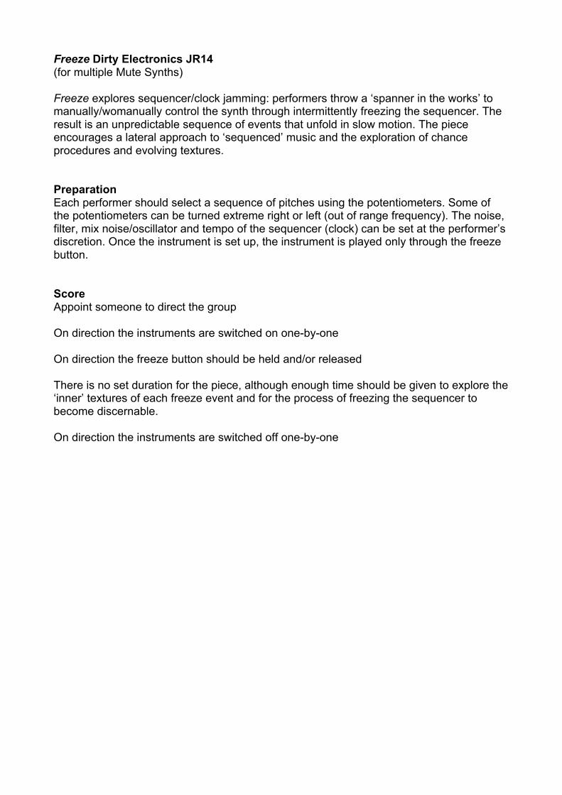
Freeze Dirty Electronics JR14 (for multiple Mute Synths) Freeze explores sequencer/clock jamming: performers throw a ‘spanner in the works’ to manually/womanually control the synth through intermittently freezing the sequencer. The result is an unpredictable sequence of events that unfold in slow motion. The piece encourages a lateral approach to ‘sequenced’ music and the exploration of chance procedures and evolving textures. Preparation Each performer should select a sequence of pitches using the potentiometers. Some of the potentiometers can be turned extreme right or left (out of range frequency). The noise, filter, mix noise/oscillator and tempo of the sequencer (clock) can be set at the performer’s discretion. Once the instrument is set up, the instrument is played only through the freeze button. Score Appoint someone to direct the group On direction the instruments are switched on one-by-one On direction the freeze button should be held and/or released There is no set duration for the piece, although enough time should be given to explore the ‘inner’ textures of each freeze event and for the process of freezing the sequencer to become discernable. On direction the instruments are switched off one-by-one

Mods & Sods Here are a few ideas, bastardisations and hacks to further explore the MSII. Many mods can be done using the patchbay without hardwiring. For more info see the Dirty Electronics website. 12 Mods 1. Jumper variable resistors (pots) - control CVs etc. with a variable resistor 2. Inputs and outputs to the patchbay (jack socket connectors) 3. Add effects using inserts (patchbay 38/39/40) 4. Multi-channel output (patchbay 38/39/40) - outputs from different parts of the signal path 5. Sequencer disabled (touch control only) - remove (patchbay 30) 6. External clock and audio signals to drive the sequencer (patchbay 28, and remove 30) 7. Audio input (distorted and modulation effects) 8. Multiplexer outputs (patchbay 31/32/33/34) to drive external devices 9. Audio output of the MSII to clock itself (use aux send from a mixing desk) - feedback chaos 10. Ergonomic controls (big!) for the patchbay - switches, pots, etc. 11. Patch-to-patch cables - hack signal paths 12. Do a hardwire mod and wire to empty/not-connected patchbay DISCLAIMER THE SELLER AND AUTHOR DISCLAIM ANY LIABILITY FOR DAMAGES AND INJURY THAT MAY RESULT FROM THE USE, PROPER OR IMPROPER, OF THE MUTE SYNTH II. THERE IS NO GUARANTEE THAT THE INFORMATION FOUND IN THE DOCUMENTATION IS COMPLETE, SAFE OR ACCURATE. THE SELLER AND AUTHOR DISCLAIM ANY LIABILITY FOR DAMAGES AND INJURY THAT MAY RESULT FROM FAULTY EXTERNAL ELECTRONIC EQUIPMENT PLUGGED INTO OR CONNECTED TO THE MUTE SYNTH II. THE MUTE SYNTH II IS FOR 9V BATTERY OPERATION ONLY John Richards 2014 [email protected]
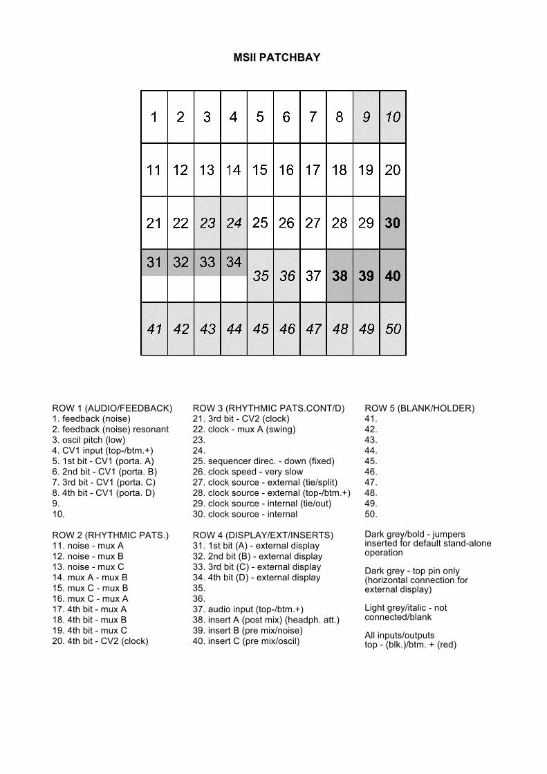
MSII PATCHBAY
ROW 1 (AUDIO/FEEDBACK) 1. feedback (noise) 2. feedback (noise) resonant 3. oscil pitch (low) 4. CV1 input (top-/btm.+) 5. 1st bit - CV1 (porta. A) 6. 2nd bit - CV1 (porta. B) 7. 3rd bit - CV1 (porta. C) 8. 4th bit - CV1 (porta. D) 9. 10. ROW 2 (RHYTHMIC PATS.) 11. noise - mux A 12. noise - mux B 13. noise - mux C 14. mux A - mux B 15. mux C - mux B 16. mux C - mux A 17. 4th bit - mux A 18. 4th bit - mux B 19. 4th bit - mux C 20. 4th bit - CV2 (clock)
ROW 3 (RHYTHMIC PATS.CONT/D) 21. 3rd bit - CV2 (clock) 22. clock - mux A (swing) 23. 24. 25. sequencer direc. - down (fixed) 26. clock speed - very slow 27. clock source - external (tie/split) 28. clock source - external (top-/btm.+) 29. clock source - internal (tie/out) 30. clock source - internal ROW 4 (DISPLAY/EXT/INSERTS) 31. 1st bit (A) - external display 32. 2nd bit (B) - external display 33. 3rd bit (C) - external display 34. 4th bit (D) - external display 35. 36. 37. audio input (top-/btm.+) 38. insert A (post mix) (headph. att.) 39. insert B (pre mix/noise) 40. insert C (pre mix/oscil)
ROW 5 (BLANK/HOLDER) 41. 42. 43. 44. 45. 46. 47. 48. 49. 50. Dark grey/bold - jumpers inserted for default stand-alone operation Dark grey - top pin only (horizontal connection for external display) Light grey/italic - not connected/blank All inputs/outputs top - (blk.)/btm. + (red)
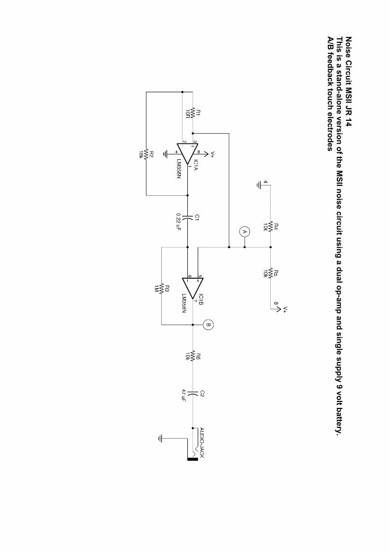
Noise C
ircuit MSII JR
14 This is a stand-alone version of the M
SII noise circuit using a dual op-amp and single supply 9 volt battery.
A/B
feedback touch electrodes

Oscillator and W
aveshaper MSII JR
14 A
triangle waveform
is taken from a tim
er integrated circuit (IC) and shaped using an op-am
p. This is a realisation of the M
SII circuit using a single timer and op-am
p.