the design of rolling bearing mountings: design … · the design of rolling bearing mountings...
TRANSCRIPT

The Design of Rolling Bearing MountingsPDF 5/8:Paper machinesLifting and conveying equipment
Rolling Bearings
FAG OEM und Handel AG Publ. No. WL 00 200/5 EA

The Design of Rolling Bearing Mountings
Design Examples covering Machines, Vehicles and Equipment
Publ. No. WL 00 200/5 EA
FAG OEM und Handel AGA company of the FAG Kugelfischer Group
Postfach 1260 · D-97419 SchweinfurtTelephone (0 97 21) 91-0 · Telefax (0 97 21) 91 34 35Telex 67345-0 fag d

Preface
This publication presents design examples coveringvarious machines, vehicles and equipment having onething in common: rolling bearings.
For this reason the brief texts concentrate on the roll-ing bearing aspects of the applications. The operationof the machine allows conclusions to be drawn aboutthe operating conditions which dictate the bearingtype and design, the size and arrangement, fits, lubri-cation and sealing.
Important rolling bearing engineering terms are print-ed in italics. At the end of this publication they aresummarized and explained in a glossary of terms, somesupplemented by illustrations.

Contents
Example Title PDF
PAPER MACHINES . . . . . . . . . . . . . . 5/8
65 Refiners . . . . . . . . . . . . . . . . . . . . . . . . . . 5/866 Suction rolls . . . . . . . . . . . . . . . . . . . . . . . 5/867 Central press rolls . . . . . . . . . . . . . . . . . . 5/868 Dryer rolls . . . . . . . . . . . . . . . . . . . . . . . . 5/869 Guide rolls . . . . . . . . . . . . . . . . . . . . . . . . 5/870 Calender thermo rolls . . . . . . . . . . . . . . . 5/871 Anti-deflection rolls . . . . . . . . . . . . . . . . . 5/872 preader rolls . . . . . . . . . . . . . . . . . . . . . . . 5/8
LIFTING AND CONVEYING EQUIPMENT
Aerial ropeways, rope sheaves
73 Run wheel of a material ropeway . . . . . . 5/874 Rope return sheaves of passenger
ropeway . . . . . . . . . . . . . . . . . . . . . . . . . . 5/875 Rope sheave (underground mining) . . . . 5/876 Rope sheave of a pulley block . . . . . . . . . 5/8
Cranes, lift trucks
77 Crane pillar mounting with a spherical roller thrust bearing . . . . . . . . . . . . . . . . . 5/8
78 Crane pillar mounting with a spherical roller thrust bearing and a spherical roller bearing . . . . . . . . . . . . . . . . . . . . . . 5/8
79 Roller track assembly . . . . . . . . . . . . . . . . 5/880 Crane run wheel . . . . . . . . . . . . . . . . . . . 5/881 Crane hook . . . . . . . . . . . . . . . . . . . . . . . 5/882 Mast guidance bearings of a
fork lift truck . . . . . . . . . . . . . . . . . . . . . . 5/8
Belt conveyors
83 Head pulley of a belt conveyor . . . . . . . . 5/884 Internal bearings for the tension/
take-up pulley of a belt conveyor . . . . . . 5/885 Rigid idlers . . . . . . . . . . . . . . . . . . . . . . . 5/886 Idler garland . . . . . . . . . . . . . . . . . . . . . . 5/8
Excavators and bucket elevators
87 Bucket wheel shaft of a bucket wheel excavator . . . . . . . . . . . . . . . . . . . . . . . . . 5/8
88 Bottom sprocket of a bucket chain dredger . . . . . . . . . . . . . . . . . . . . . . . . . . . 5/8
89 Drive unit of a finished-goods elevator . . 5/8

65–72 Paper Machines
Modern paper machines are extensive plants which fre-quently stretch well beyond 100 m in length and havenumerous rolls. The demand for utmost operationalreliability is priority number one when designing anddimensioning bearing locations: if trouble arises at justone roll the whole plant has to be shut down. For thisreason the bearings are designed for a far longer nomi-nal life (index of dynamic stressing fL = 5...6) than inother industrial equipment. A high degree of cleanli-ness in the bearings is decisive for a long service life.This demands utmost sealing reliability, particularlyagainst moisture, and design diversity based on thetype of roll in question.
Lubrication also influences the bearing life greatly. Allroll bearings in modern paper machines are connectedto an oil circulation system for operational reliabilityand maintenance purposes. The bearings in the wetend section of older paper machines are still lubricatedwith grease (lower environmental temperatures).
In the dryer section, bearings for rope sheaves, spread-er rolls and sometimes guide rolls are still lubricatedwith grease.Due to high temperatures in the area of the dryer roll,bearing lubrication is particularly critical. Thereforeoils of the viscosity class ISO VG 220 or 320 are used.Lightly doped mineral oils and synthetic oils are suitable(high ageing stability), which correspond to the re-quirements for dryer roll oils and have proven them-selves in the field or successfully stood dynamic testingon the FAG test rig FE8.Lubrication can be improved considerably (increasingthe operating viscosity) by insulating the hollow jour-nals of the dryer rolls and thus reducing the bearingtemperature.The following examples show the structure of somemain bearing locations in the paper industry, for exam-ple refiners, suction rolls, press rolls, dryer rolls, guiderolls, calender thermo rolls, anti-deflection rolls andspreader rolls.
Wet end section
large extent of waterenvironmental temperature < 50°C
Suction roll
Anti-deflection roll
Press section
Guide roll
Dryerroll
Thermo roll
high humidityenvironmental temperature > 100°C( ) ( )
Dryer section
Paper guide roll
Finishing group
Forming section
DuoStabilizerroll
Anti-deflectionroll
Spreader roll
Formingroll
Spreaderroll
Spreader roll
A modern paper machine

65 Refiners
Wood chips from the wood chopper which have beensoftened and steamed by water are broken down andcrushed in the refiner by means of crushing wheels ro-tating in reverse motion with knife sections. Tempera-tures up to 160 °C result from this process (steamedwood chips, crushing) and can lead to increased oper-ating temperatures in bearings depending on theirconstruction.
Operating data
Axial load from crushing process 400 kN;Radial load (rotor/shaft) 15 kN per bearing;Speed 600 min–1;Temperature in locating bearing 80 °C, in floatingbearing 70 °C.
Bearing selection, dimensioning
With the high axial loads which have to be accommo-dated, an attainable life Lhna ≥ 80,000 hours is re-quired. A second thrust bearing is necessary since theaxial load acts mainly in the direction of the locatingbearing but can also be acting in the opposite direc-tion. Thus the locating bearing arrangement is made upof two symmetrically arranged spherical roller thrustbearings FAG 29460E. For the rollers to remain undis-turbed when the axial load is "reversed" both bearingsmust be preloaded with springs (minimum load) at theouter rings. A spherical roller bearing FAG 23052K.MB is mount-ed as a floating bearing and can easily accommodateshaft deflection. Thermal length variations of the shaftare compensated for in between bearing outer ring andhousing (sliding fit). The bearing is mounted directlyon the tapered shaft seat and fastened with a locknutHM3052.The floating bearing reaches a nominal life Lh of wellover 200,000 hours. Excellent bearing lubrication isrequired due to slippage hazard when loads are low(P/C ≈ 0.02). A nominal life of Lh = 50,600 h is calculated for the leftlocating bearing 29460E. With oil circulation lubrica-tion, good cleanliness and a bearing temperature of 70 °C, factor a23 is 3.2. An attainable life Lhna =162,000 h results from the adjusted life calculation.
The right locating bearing only has a slight axial load (spring preload). The attainable life Lhna is over200,000 h for this bearing.
Machining tolerances
Floating bearing: The inner ring has circumferentialload and is attached to the tapered bearing seat of theshaft.Roundness tolerance IT5/2 (DIN ISO 1101);Taper angle tolerance AT7 (DIN 7178).Bearing seat of housing bore according to G7.
Locating bearing: For mounting reasons, both shaft andhousing washer are in sleeves. The bearing seats aremachined according to k6 and G7 for the shaft sleevesand housing sleeves respectively.
Lubrication
A lubricating oil ISO VG 150 with EP additives is usedfor locating and floating bearings.The radial spherical roller bearing has oil circulationlubrication with 0.8 l/min. Oil jet lubrication is pro-vided for the spherical roller thrust bearings. This en-sures adequate oil constantly at the highly-stressedcontact areas between roller face and lip. The oil is supplied through the side of the bearing via the spacersleeve. The minimum oil flow rate for both bearings is8 l/min (good heat dissipation from bearing). The oilis filtered in cirulation and cooled back to a tempera-ture of 40 °C.
Sealing
There are two labyrinths on the side of the crushingwheel connected to one another and filled with greasewhich protect the bearings from water and contamina-tion and prevent oil escaping from the bearings. Onthe outer side of the locating bearing a shaft sealing ringprevents oil escape.

65: Refiner bearings
Locating bearingFloating bearing

66 Suction rolls
Suction rolls are found in the wire or press section of apaper machine. They are hollow cylinders up to 10 min length which have several small holes all aroundtheir circumference. Some water is removed from theweb due to the rotating roll shell and the vacuum in-side the roll. The suction box, as interior axle, is sta-tionary. The roll shell is driven by planet wheels inmodern paper machines.
Operating data
Roll length 7,800 mm; roll diameter 1,600 mm; rota-tion 278 min–1 (speed 1,400 m/min); roll weight 270 kN; wire tension 5 kN/m.
Bearing selection, dimensioning
The diameter of the suction box is decisive for the sizeof the bearing. We recommend bearings with a dynam-ic load rating as low as possible; the higher specificbearing load reduces the danger of slippage. Self-align-ing bearings are necessary as misalignment could arise.Roll weight, wire tension and rotational speed are themain criteria for dimensioning the bearings.FAG spherical roller bearings FAG 239/850K.MB.C3with tapered bore (K 1:12) and increased radial clear-ance are used. The bearings are mounted directly onthe tapered shaft seats for running accuracy reasons.The hydraulic method is applied to facilitate mount-ing.The locating bearing provides axial guidance for therolls while the floating bearing compensates for any
length variations caused by displacement of the outerring in the housing bore.The nominal life for both bearings is Lh > 100,000 h.The attainable life reaches over 200,000 h when theoperating temperature is 60 °C and oil ISO VG 68(viscosity ratio k > 2; factor a23 = 2.2) is used.
Machining tolerances
The inner ring has circumferential load and is attachedto the tapered bearing seat of the shaft.Roundness tolerance IT5/2 (DIN ISO 1101); taperangle tolerance AT7 (DIN 7178).Housing bores according to G7 due to point load at theouter ring.
Lubrication
The spherical roller bearings are supplied by circula-tion lubrication with a mineral oil quantity of 8 l/min.A mineral oil with sufficient viscosity and EP additives isselected. Additives with good anti-corrosive propertiesand water separation ability are also required. An effec-tive lubrication is achieved with an oil supply to thecentre of the bearing.
Sealing
Any oil which escapes is thrown off via splash groovesinto oil collecting chambers and directed back. At theroll side a baffle plate and multiple grease-filled laby-rinth with integrated V ring prevent water penetratingfrom the outside.
66: Suction roll bearings
Floating bearing Locating bearing

67 Central press rolls
The paper web runs through the press rolls on a feltcloth and a large amount of water is pressed out of it.Modern press sections consist of one central press rollagainst which one or more (suction) press rolls arepressed. The central press roll is solid, made of gran-ite/steel or steel with a protective coating.
Operating data
Roll length 8,800 mm; roll diameter 1,500 mm; speed1,450 m/min; roll weight 750 kN. Pressure by 3 rollsat 30°, 180° and 210°; bearing temperature about 60 °C. Direct drive.
Bearing selection, dimensioning
Self-aligning spherical roller bearings of the series 231or 232 with a very high load carrying capacity are cho-sen due to the high radial load and the misalignmentwhich is possible between the bearing locations. A lowcross section height is also important for these bearingssince the height of the housing is restricted by the rolldiameter. The roll weight and the load components ofthe pressure rolls yield a resulting bearing load Fr = 300 kN.A spherical roller bearing FAG 231/600K.MB.C3 ismounted at every bearing location. The bearings withtapered bore (taper 1:12) are pressed directly onto thetapered shaft seat by means of the hydraulic method.The floating bearing at the operator's end permits tem-perature-depending length variations of the roll byshifting the outer ring in the housing. The locatingbearing is at the drive end.
The nominal life calculated is Lh > 100,000 h with aspeed of 308 min–1. With good lubrication (viscosityratio k ≈ 3, basic factor a23II = 3) and improved cleanli-ness (contamination factor V = 0.5) in the lubricatinggap Lhna @ 100,000 h according to the adjusted ratinglife calculation.
Machining tolerances
The inner ring has circumferential load and is attachedto the tapered bearing seat of the shaft.Roundness tolerance IT5/2 (DIN ISO 1101); taperangle tolerance AT7 (DIN 7178).Housing bores according to G7 since there is pointload at the outer ring.
Lubrication
The spherical roller bearings are supplied with a mini-mum oil quantity of 7 l/min by circulation lubrication.A mineral oil of sufficient viscosity (ISO VG 100) andEP additives is used. Additives with good anti-corrosiveproperties and water separation ability are also re-quired. An effective lubrication is achieved with an oilsupply to the centre of the bearing.Oil returns to both sides of the bearing via oil collect-ing pockets and connecting holes.
Sealing
Oil splash grooves in the roll journal prevent oil escap-ing at the cover passage. Non-rubbing and maintenance free gap-type seals pro-tect the bearings from environmental influences.
67: Central press roll bearings
Locating bearing Floating bearing

68 Dryer rolls
The remaining water in the dryer section is evaporat-ed. The paper runs over numerous heated dryer rollsguided by endless dryer wires (formerly dryer felts).The dryer rolls are steam heated (temperature dependson the type of paper, its thickness and speed, and onthe number of dryer rolls). The high temperatures ofthe heating steam transfer to the bearing seats stressingthe rolling bearings accordingly. Today, the journalsthrough which the steam flows are insulated in orderto keep bearing temperatures low.
Operating data
Working width 5,700 mm; roll diameter 1,800 mm;paper speed 1,400 m/min (rotational speed 248 min–1);heating temperature 165 °C (7 bar); roll weight 90 kN.Felt pull 4.5 kN/m; wrap angle 180°; environmentaltemperature under the dryer section hood approx. 95 °C; insulated journal bores.
Bearing selection
The bearing load is calculated from the roll weight, feltpull and temporary water fill. The floating bearing isloaded with 75 kN, the locating bearing with 83 kNtaking into account the drive force. Heating the dryerroll leads to heat expansion which in turn leads to con-siderable changes in length with such long rolls. Self-aligning rolling bearings are necessary due to the mis-alignment arising between both bearing locations.A double-row cylindrical roller bearing of the dimen-sion series 31 is provided as floating bearing at theoperator's end. It easily compensates for length varia-tions in the bearing between the rolls and the innerring raceway. With its spherical sliding surface a plainspherical bearing's seating ring accommodates anyalignment inaccuracy of the journal. A double-rowself-aligning cylindrical roller bearing FAG566487K.C5 with the dimensions 200x340x112 mmis mounted. A spherical roller bearing FAG23140BK.MB.C4 is mounted as locating bearing onthe drive end.Both bearings have about the same operating clearancein order to avoid any detrimental preload during theheating-up stage which may lead to a maximum tem-perature difference of 50 K. The spherical roller bear-ing has an increased radial clearance according to C4(260...340 microns), the cylindrical roller bearing anincreased radial clearance according to C5 (275...330microns).
Both bearings have a tapered bore (K 1:12) and aremounted by the hydraulic method directly onto the tapered journals.
Since the cylindrical roller bearing and the sphericalroller bearing have the same dimensions unsplit PMDplummer block housings (FAG PMD3140AF or BF)are applied both at the drive end and at the operator'send.
Due to increased operating temperature, both bearingsare given special heat treatment (isotemp) and are thusdimensionally stable up to 200 °C.
Bearing dimensioning
An attainable life Lhna ≥ 250,000 hours is required fordryer roll bearings. Lubrication decisively influencesthe adjusted rating life. Under an average operatingtemperature of 100°C the operating viscosity n ≈16 mm2/s for a mineral oil with a nominal viscosity of220 mm2/s (ISO VG 220). The rated viscosity is determined from the speed andthe mean bearing diameter dm = (200 + 340)/2 = 270 mm to n1 = 25 mm2/s.The viscosity ratio is then:k = n/n1 = 16/25 = 0.64.With the value K = 1 a basic factor a23II = 1.1 is ob-tained for the spherical roller bearing. The values K = 0 and a23II = 1.4 apply to the cylindri-cal roller bearing. With normal cleanliness (cleanliness factor s = 1) thefactor a23 = a23II · s1.1 for the spherical roller bearing,1.4 for the cylindrical roller bearing. The attainable life Lhna = a1 · a23 · Lh is therefore wellover 250,000 h for both bearings.
Machining tolerances
The inner rings have circumferential load and have atight fit on the tapered roll journal. The journals haveoil ducts so the bearings can be mounted and dis-mounted by means of the hydraulic method. Round-ness tolerance IT5/2 (DIN ISO 1101), taper angle tol-erance AT7 (DIN 7178). Bearing seats in the housingbore according to G7.

Lubrication
The bearing housings are connected to a central oil cir-culation lubrication system so that heat is constantlydissipated from the bearing. High-grade mineral oilsISO VG 220 or 320 are used which must have a highoperating viscosity, thermal stability, good protectionagainst wear, good water separation ability and a highdegree of cleanliness. A minimum oil quantity of 1.6l/min is guided directly to the centre of the bearing viaa lubricating groove and lubricating holes in the outerring.The oil can be carried off at both sides of the bearingwith the central oil system. The danger of oil retention
and leakage is minimized considerably. Any contami-nants or wear particles which might penetrate thebearing are immediately washed out of it with thismethod of lubrication.
Sealing
Gap-tape seals, which are non-rubbing and mainte-nance-free, are provided as sealing for the journal pas-sages. The oil is thrown off via splash grooves and oilcollecting chambers and flows back through returnholes to the two oil cavities on the housing floor. Coverseals make the housing of the paper machine oil proof.
68: Dryer roll bearings
Locating bearing Floating bearing

69 Guide rolls
Guide rolls guide, as the name indicates, and turn thewire and felt cloth in the wet end and dryer sections ofa paper machine. The same bearings are used for theguide rolls in both areas. Lubrication and sealing differ,however, depending on the place of application. In older machines the wet end section is usually lubri-cated with grease, and the dryer section with oil.In modern machines both sections have oil circulationlubrication. Due to different operating conditions separate oil circuits are necessary for the wet end anddryer sections. The larger the machine the more often it is found tobe faster. For this reason the bearing inner rings aremounted with a tapered bore directly on the taperedroll journal.
Wet end sectionDepending on the positions of the bearings in the ma-chine they are subject to a small or large degree ofmoisture. Water must not penetrate the housing par-ticularly when machines are being high-pressurecleaned.
Dryer sectionEnvironmental temperatures of about 95 °C lead togreat length variations and place high demands on lubrication. The operating temperature of the bearingscan be 115 °C.
Operating data
Useful width 8,800 mm Roll diameter 700 mm Paper speed 1,650 m/min (n = 750 min–1) Roll weight FG ≈ 80 kN Paper pull 1 kN/m (tensile load Fz ≈ 9 kN) Wrap angle 180°Bearing temperature approx. 105 °C
Bearing selection, dimensioning
The bearings must be able to accommodate loads andcompensate for misalignment at the same time (mis-alignment, bending). An increased radial clearanceaccording to C3 is necessary due to temperature differ-ences. Spherical roller bearings FAG 22330EK.C3 aremounted.
Bearing load:
P = (FG + Fz)/2 = (80 + 9)/2 = 44.5 kN
The diameter of the roll journal is determined by theroll rigidity required. As a result there is a high index ofdynamic stressing fL corresponding to a nominal life Lhof well over 200,000 hours. The attainable life is evenhigher with such good lubrication conditions.
The housings can be in standing or suspended positionor can be laterally screwed on. They are designed foroil circulation lubrication.
Machining tolerances
The inner rings have circumferential load and are di-rectly fitted to the tapered roll journal. The roll journalhave oil ducts so the bearings can be mounted and dis-mounted with the hydraulic method.Roundness tolerance IT5/2 (DIN ISO 1101); taperangle tolerance AT7 (DIN 7178).
Bearing seats in the housing bore according to G7.
Lubrication
In the dryer section: see example 68 (Dryer rolls) sincethe bearings are connected to the oil circuit of the dryer rolls. Minimum flow rate 0.9 l/min.
In the wet end section: see example 66 (Suction rolls)and 67 (Central press rolls), since the bearings are con-nected to the oil circuit of the wet section rolls. Minimum flow rate 0.5 l/min.
Sealing
Gap-type seals, which are non-rubbing and mainte-nance-free, prevent oil from escaping through the cov-er passages in the dryer section.
The bearings in the wet end section must have relubri-catable labyrinth seals to prevent water from penetrat-ing. Remaining oil is thrown off by splash grooves intocollecting chambers and directed back. Cover sealsmake the housing oilproof.

69: Guide roll bearings (dryer section)
Locating bearingFloating bearing

70 Calender thermo rolls
The paper passes through the so-called calender stackafter leaving the dryer section. Soft calenders smooththe surface of the paper thus improving its printability.The calender consists of two pairs of rolls. One calend-er roll (steel) lies above a counter roll, another belowone. The counter roll is the so-called anti-deflectionroll (elastic material). Soft calender rolls can be heatedby water, steam, or oil. The gap or the "nip" pressuredepends on the type of paper.
Operating data
Useful width approx. 7 m Rotation 350 min–1 (speed 1,100 m/min) Heated by oil at 200...250 °C Insulated roll journal Operating temperature at bearing inner ring 130 °C.
Bearing selection, dimensioning
The radial bearing load depends on the application ofthe calender roll as lower or upper roll, on the weightFG and the variable pressure load with percentage oftime.
P1 = FG + Fnip min = 600 kNP2 = FG + Fnip med = 990 kNP3 = FG + Fnip max = 1,260 kNP4 = FG – Fnip min = 60 kNP5 = FG – Fnip med = 390 kNP6 = FG – Fnip max = 720 kN
Percentages of time: P1, P4 : 10 % eachP2, P3, P5, P6 : 20 % each
The sum of the roll weight and the nip load acts forthe application as bottom roll whereas their differenceacts for the application as top roll.
Taking the maximum load for designing the bearingwould lead to overdimensioning (equivalent dynamicload P < 0.02 · dynamic load rating C) in the case of application in the top roll. Slippage may occur withsuch a low load which in turn can lead to bearing dam-age when lubrication is inadequate. In order to avoidthis problem, smaller bearings with a smaller dynamicload rating C should be selected so that P/C > 0.02.The risk of breaking through the lubricating filmdrops with the smaller roller mass.
Requirements with respect to load carrying capacityand self-alignment are met by spherical roller bearings.The cross section height of the bearing is limited bythe diameter of the roll journal and roll shell. The relatively wide spherical roller bearings FAG231/560AK.MB.C4.T52BW are mounted.The nominal life Lh = 83,000 h with given loads andpercentages of time.
With a lubricating oil ISO VG 220 the viscosity ratiois k = 0.71 under an operating temperature of 130 °C.An attainable life Lhna > 100,000 h is obtained with theadjusted rating life calculation (where fs* > 12; a23II =1.2; V = 0.5; s = 1.6).
The increased radial clearance C4 is required due tothe danger of detrimental radial preload in the bearingduring the heating up phase when the temperature difference is great. With a speed index n · dm = 224,000 min–1 · mm we recommend bearings with increased running accuracy according to specificationT52BW.
Machining tolerances
The inner rings have circumferential load and are di-rectly fitted on the tapered roll journal. The roll jour-nals have oil ducts so that the hydraulic method can beapplied for mounting and dismounting the bearings. Roundness tolerance IT5/2 (DIN ISO 1101), taperangle tolerance AT7 (DIN 7178).Bearing seats in the housing boring according to F7.
Lubrication
Oil circulation lubrication with a synthetic oil ISO VG220, suitable in quality, which has stood dynamic test-ing on the FAG test rig FE8.By supplying a large amount of oil to the centre of thebearing (minimum flow rate 12 l/min) heat dissipationis achieved as well as a low thermal stress of the oil.Any contaminants or wear particles are washed out ofthe bearing. Oil returns at both sides of the bearing viaoil collecting pockets and connecting holes.
Sealing
Angle rings at the roll side prevent direct oil escape atthe cover holes. Remaining oil is thrown off by splashgrooves into collecting chambers and directed back.Cover seals make the housing oilproof.

70: Calender thermo roll bearings
Floating bearing Locating bearing

71 Anti-deflection rolls
Anti-deflection rolls are found in both the press sec-tion and in calenders. They provide for an even paperthickness across the web and a consistently high paperquality. The drive is at the locating bearing end. Itspower is transmitted via gearing and the hypoid teethcoupling to the roll shell.The adjustment roll is pressed against the mating roll(calender roll) under very high pressure. As a result themating roll is bent and the form of the roll shellchanged. The shell of the adjustment roll must adjustto this form. The anti-deflection roll consists of a stationary axleand a rotating roll shell. Control elements which canbe pressure-balanced separately are provided on theaxle. They support the roll shell hydrostatically and effect its adjustment. The roll shell is shaped like thebent mating roll by the changing pressure giving thepaper an even thickness.
Operating data
Roll length 9,300 mm; roll diameter 1,025 mm; rollweight 610 kN; shell weight 210 kN; pressure 700 kN;circumferential velocity 1,500 m/min (n = 470 min–1);bearing temperature 55 °C.
Bearing selection, dimensioning
A service life of > 100,000 h is required. The bearingonly has a guidance function when in operation (withpressure and closed gap). Spherical roller bearings FAG 23096MB.T52BW (dynamic load rating C = 3,800 kN) are used.
Due to the danger of slippage bearings of the series239 with a low load rating should be selected. The bearings are produced with a reduced radial run-out (specification T52BW), since running inaccuracyof the rotating roll shell influences the quality of thepaper web.
Machine tolerances
Bearing seats on the axle according to f6 due to pointload for the inner rings.The outer rings have circumferential load and a tight fit;the bearing seats in the housings are machined to P6.
Lubrication
When dynamic misalignment and/or slippage may occur, a very good lubrication system must always pro-vide a load-carrying lubricating film. The bearings aresupplied with the lubricating oil used for the hydraulicsystem (ISO VG 150 with EP additives). The oil is fedlaterally to the bearings via holes. In new designs andparticularly with heated rolls, the lubricating oil is fedvia lubricating holes in the inner ring directly to thebearing contact areas.The deep groove ball bearings of the transmission ar-ranged at the locating bearing side are supplied with oilvia a separate oil circuit.
Sealing
The bearings are sealed externally with a shaft seal. Tothe roll side a baffle plate provides for an oil reservoirin the bearing area.
71: Anti-deflection roll bearings
Floating bearing Locating bearing

72 Spreader rolls
Paper webs transported in lengthwise direction tend tocreasing. Spreader rolls stretch or expand in cross di-rection the webs running over them. They flattencreases and any middle or end parts of the web whichare loose. Spreader rolls consist of a stationary axlewhich is bent symmetric to its longitudinal axis, andaround which the roll shell rotates. Tube-shaped sec-tions make up the roll shell and are arranged to rotatefreely and have angular freedom. The sections adjust toone another in such a way that the bending form ofthe axle is reflected on the shell surface. Depending onthe case of application – wet end section, dryer section,or subsequent processing – the sections are made ofstainless steel or provided with a flexible coating (e.g.rubber).
Operating data
Roll length 8,300 mm, consisting of 22 sections;weight/section plus wire or paper web pull at 30° wrapangle 2 kN/m; a radial load of just 0.5 kN per bearingresults therefrom.Rotation of roll shell 1,160 min–1.Operating temperature in the wet end section 40 °C;in the dryer section and in subsequent processing withinfrared drying temperatures can reach 120 °C.
Bearing selection, dimensioning
With rotating outer ring, extremely smooth running isrequired from the bearings since the sections in the wetend section and in the dryer section or subsequent pro-cessing are only driven by the wire tension and thepaper web respectively.High operational reliability is also necessary since thefailure of one bearing alone means that the wholespreader roll has to be dismounted.
FAG 61936.C3 deep groove ball bearings are selected.The increased radial clearance C3 permits easy adjust-ment of the sections. With the low load, the bearingshave a nominal life Lh of well over 100,000 hours.
Machining tolerances
As the outer ring of the bearing rotates with the rollshell it is given a tight fit with M6 tolerance and is se-cured axially by a snap ring.The inner ring has point load and is fitted to the shaftsleeve with h6. Due to the bent roll axle and for assem-bly reasons the sleeve is loosely fitted and axially at-tached with a screw.
Lubrication
The bearings are greased for life, i.e. no relubrication isprovided for. The selection and filling quantity of lu-bricating grease is determined by the demand forsmooth running as well as a service life of up to fiveyears (8,000 operating hours per year). Low-frictiongreases (e.g. greases of class LG10 for the wet end sec-tion) are advantageous with high speeds and low loads.
Sealing
Non-rubbing dust shields are used for sealing due tothe smooth running required. They are stuck to thebearing outer ring on both sides so the base oil centri-fuged from the lubricating grease cannot escape. Roundcord seals also provide for oil tightness.
72 Spreader roll bearings

73 Run wheel of a material ropeway
Operating data
Speed n = 270 min–1; radial load Fr = 8 kN. Thrustloads as guidance loads only, considered by 20 % ofthe radial load: Ka = 1.6 kN.
Bearing selection
Each run wheel is supported by two tapered rollerbearings FAG 30306A. The bearings are assembled inO arrangement which provides for a wider bearingspread than an X arrangement. The wider the spread,the lower the additional bearing load from thrust loadKa.
Bearing dimensioning
As thrust load Ka acts at the wheel circumference, itgenerates radial reaction forces at the bearing loca-tions.
Thus,FrA/Y = 6.1/1.9 = 3.2; FrB/Y = 1.9/1.9 = 1 and consequently FrA/Y > FrB/Y
The second condition proven isKa > 0.5 · (FrA/Y – FrB/Y) = 0.5 (3.2 – 1) = 1.1For calculation of bearing A the following thrust loadFaA must, therefore, be taken into account:FaA = Ka + 0.5 · FrA/Y = 1.6 + 0.5 · 1.9/1.9 = 2.1 kN
Consequently, the equivalent dynamic load PA of bear-ing A is:
PA = 0.4 · FrA + Y Fa = 0.4 · 6.1 + 1.9 · 2.1 = 6.45 kNWith this load, the indicated dynamic load rating andthe speed factor fn = 0.534 (n = 270 min–1) the index ofdynamic stressing.
fL = C/PA · fn = 60/6.45 · 0.534 = 4.97
This value corresponds to a nominal rating life of morethan 100,000 hours. Since this calculation is based onthe most unfavourable load conditions, the thrust loadacting constantly at its maximum and only in one di-rection, the bearing is adequately dimensioned with re-gard to fatigue life. The service life will probably be ter-minated by wear, especially under adverse operatingconditions (high humidity, heavy contamination).The load carrying capacity of bearing B does not needto be checked since its loading is much less than thatof bearing A.
Machining tolerances
The run wheel mounting is a so-called hub mounting,i.e. the run wheel, with the two cups, rotates about astationary shaft. The cups carry circumferential loadand are thus tight-fitted. The shaft is machined to h6,the hub bore to M6.
Lubrication, sealing
The bearings and the free spaces have to be filled dur-ing mounting with grease, e. g. FAG rolling bearinggrease Arcanol L186V. The grease filling will last forapproximately one year.
In the example shown, the bearings are sealed byspring steel seals (Nilos rings).
Bearing A:FrA = Fr/2 + Ka · (D/2)/l = 4 + 1.6 · 125/95 = 6.1 kNThe thrust load Ka = 1.6 kN acts toward bearing A.Bearing B:FrB = Fr/2 – Ka · (D/2)/l = 4 – 1.6 · 125/95 = 1.9 kN
Radial loads acting on a shaft supported on two ta-pered roller bearings generate axial reaction loadswhich have to be considered in the calculation of theequivalent dynamic load. These internal loads togetherwith the external thrust loads should, therefore, be tak-en into account for life calculation (see FAG catalogueWL 41 520, chapter "Tapered roller bearings").
Data for tapered roller bearings FAG 30306A (desig-nation to DIN ISO 355: T2FB030):dynamic load rating C = 60 kN,Thrust factor Y = YA = YB = 1.9.

73: Run wheel of a material ropeway
Rope

74 Rope return sheaves of a passenger ropeway
In this example of a passenger ropeway, eight sheavesare installed at the mountain station and another eightat the valley station including the sheaves in the valleystation tensioning weight pit. The sheave diameters are2.8 and 3.3 meters.
Bearing selection, dimensioning
The valley station sheaves and the tensioning weightsheaves are fitted with spherical roller bearings FAG22234E. The sheaves at the mountain station are sup-ported by spherical roller bearings FAG 22240B.MB.
The load on the bearings FAG 22234E installed in thetensioning weight sheaves is P = 65 kN each; with a dynamic load rating C = 1,100 kN and a speed factor fn= 0.838, corresponding to a speed of 60 min–1, the index of dynamic stressing:
fL = C/P · fn = 1,100/65 · 0.838 = 14.2.
This shows that the bearings are more than adequatelydimensioned with regard to fatigue life.
The one-piece sleeve carrying the bearings allows con-venient changing of the rope sheaves.
Machining tolerances
The outer rings carry circumferential load and require,therefore, a tight fit. To safeguard the spherical rollerbearings against detrimental axial preloading, the de-sign is of the floating mounting type. The outer ringsare securely locked via the two covers by means of aspacer ring. The centre lip of sleeve H is slightly nar-rower than the spacer so that the sheave can float axial-ly on the sleeve via the loosely fitted inner rings. Thesleeve is locked to prevent it from rotating with the in-ner rings.
Sleeve to g6; hub bore to M6;
The sleeve has a sliding fit on the shaft.
Lubrication, sealing
Grease lubrication with FAG rolling bearing grease Arcanol L186V. Relubrication by means of lubricatingholes in the shaft.
A shaft seal ring in the covers provides adequate pro-tection against contamination.
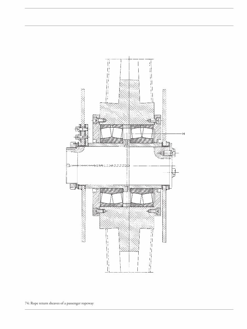
74: Rope return sheaves of a passenger ropeway

75 Rope sheave (underground mining)
These sheaves are arranged in the head frames of thepits. The rope fastened to the cage runs from the drivesheave or the drum of the hoist into the mine by pass-ing over the rope sheaves.
Operating data
Static rope load 452 kN; weight of rope sheave andshaft 75 kN; rope sheave diameter dS = 6.3 m; haulagespeed v = 20 m/s; wrap angle 140°.
Acceleration forces are taken into account by assuming10 % of the static rope load.
The recommended index of dynamic stressing fL is4...4.5. With 4.5, the nominal rating life is about75,000 hours. It should be borne in mind that only inrare cases the rope sheave bearings fail due to materialfatigue; usually their service life is terminated by wear.
Thus, the required dynamic load rating C for the spher-ical roller bearing is calculated as follows:
C = fL/fn · P = 4.5/0.838 · 500 = 2,680 kN
Spherical roller bearings FAG 23252BK.MB with a dynamic load rating C = 2,900 kN were chosen.
The bearings feature a high load carrying capacity andcompensate for potential housing misalignments, shaftdeflections and deformations of the head frame.
Machining tolerances
One bearing acts as the locating bearing, the other oneas the floating bearing. Both bearings have a taperedbore (K 1:12). They are mounted on the shaft journalwith withdrawal sleeves (FAG AH2352H). Mountingand dismounting is simplified by using the hydraulicmethod. For this purpose the withdrawal sleeves fea-ture oil grooves and ducts. The spherical roller bear-ings are supported by FAG plummer block housingsFS3252AHF and FS3252AHL.
Shaft journal to h6, cylindricity tolerance IT5/2 (DINISO 1101). Housing to H7.
Lubrication, sealing
Grease lubrication with FAG rolling bearing grease Arcanol L186V. A multiple labyrinth protects the bearings against contamination. Replenishment of labyrinth grease iseffected about every 4...6 weeks.
Bearing selection, dimensioning
From the parallelogram of forces the resultant load isapproximately 1,000 kN. Since the two bearings aresymmetrically arranged, the radial load per bearing is P = 500 kN.
Speed n = v · 60/(dS · π) = 20 · 60/(6.3 · 3.14) = 60 min–1; this yields a speed factor fn = 0.838.
452 kN452 kN
Additional load 10 %
Additional load 10 %
Sheave andshaft 75 kN
1000 kN

75: Rope sheave (underground mining)
Floating bearingLocating bearing

76 Rope sheave of a pulley block
In pulley blocks it is customary to arrange severalsheaves on a common shaft. To achieve minimumoverall pulley block width, the sheaves and their bear-ings should, therefore, be as compact as possible.
Bearing selection
For the rope sheaves of pulley blocks the wrap angle is180°. Thus the radial load on the bearing is twice therope pull. Thrust loads, resulting from a possible in-clined rope pull, and the moments caused by them arelow and can be neglected for bearing life calculation.Adequate bearing spread for load accommodation isachieved by mounting either two bearings or one double-row bearing. Deep groove ball bearings are satisfactory for accommodating the loads in this appli-cation.The bearings are mounted on a sleeve, forming aready-to-mount unit with the sheave which can be easily replaced.
Operating data and bearing dimensioning
Rope pull S 40 kNBearing loadF = 2 · S 80 kNSpeed n 30 min–1
Speed factor fn 1.04Bearings mounted 2 deep groove ball bearings
FAG 6220Dynamic load rating C = 2 x 122 kNEquivalent dynamic load P = F/2 = 40 kNIndex of dynamic stressing fL = C/P · fn
= 122/40 · 1.04 = 3.17Nominal rating life Lh = 16,000 h
Usually, an index of dynamic stressing fL = 2.5...3.5 isused for rope sheaves. This corresponds to a nominalrating life of 8,000 to 20,000 hours.Thus the bearings are adequately dimensioned com-pared with established field applications.
Machining tolerances
The mounting is a so-called hub mounting, i.e. thepulley, with the outer rings, rotates about a stationaryshaft. The outer rings carry circumferential load and arepress-fitted: hub to M7.The inner rings carry point load allowing a loose fit orsliding fit: shaft sleeve to g6 or h6.
Lubrication, sealing
The sheave bearings are lubricated with lithium soapbase grease of penetration class 3 (Arcanol L71V). Highloads (load ratio P/C > 0.15) require a lithium soapbase grease of penetration class 2 and EP-additives(Arcanol L186V). One grease filling normally lasts forseveral years.
The rope sheave in this example is sealed by springsteel seals (Nilos rings).
76: Rope pulleys with deep groove ball bearings

77–78 Gantry of a floating crane
Floating cranes are used in harbours for transportationof heavy and bulky goods, in shipyards for repair workand for ship outfitting. Due to their mobility they arean ideal complement to stationary cranes.
The pillar of the crane described is attached to theship. The slewing gantry with the crane superstructureis supported on the crane pillar. The bearing mountinghas to take up the weight of the superstructure and thepayload. Since the common centre of gravity of pay-load and gantry is outside the pillar axis, a tilting mo-ment is produced causing horizontal reaction forces inthe bearings at the upper and lower pillar end.
At the upper pillar end the gantry runs on the so-calledpillar bearing mounting. It consists either of one singlespherical roller thrust bearing or one spherical rollerbearing combined with one spherical roller thrustbearing, depending on the amount of radial loading.
At the pillar foot the gantry is supported on a roller-track assembly (see example no. 79).
Gantry
Crane pillar bearing
Crane pillarRoller track assembly

77 Crane pillar mounting with a spherical roller thrust bearing
Operating data
Thrust load (crane superstructure and payload) Fa =6,200 kN; radial load (reaction forces resulting fromtilting moment and wind pressure) Fr = 2,800 kN;speed n = 1 min–1.
Bearing selection, dimensioning
The thrust load, consisting of the weight of the slew-ing superstructure and the payload, is much higherthan the radial load resulting from the tilting momentand wind pressure. Therefore, the crane pillar bearingmust have a high thrust load carrying capacity. More-over, the bearing must be self-aligning to compensatefor misalignment and elastic deformation unavoidableon these crane structures. Due to the low speed of 1 min–1 the bearing is chosen with regard to its staticload carrying capacity.A spherical roller thrust bearing FAG 294/630E.MBwith a static load rating of C0 = 58,500 kN; factor X0 =2.7 is selected.
For spherical roller thrust bearings under combinedload the ratio Fr/Fa must be small in order to ensurethat most of the rollers transmit loads. Condition:Fr/Fa ≤ 0.55.
In this example
Fr/Fa = 2,800/6,200 = 0.45
Thus the equivalent static load
P0 = Fa + X0 · Fr = Fa + 2.7 · Fr= 6,200 + 2.7 · 2,800 = 13,800 kN
The index of static stressing
fs = C0/P0 = 58,500/13,800 = 4.24
Thus, the requirement fs ≥ 4 for spherical roller thrustbearings (FAG catalogue WL 41 520) whose housingand shaft washers – as in this example – are fully sup-ported is met.
With fs values ≥ 4...≤ 6 the shaft washer and the hous-ing washer must be fully supported axially, and goodradial support of the housing washer must also be pro-vided.
Machining tolerances
Shaft washer to j6; housing washer to K7
Lubrication, sealing
Oil bath lubrication, with the rollers fully immersed inoil. The oil level should be maintained to the upperedge of the shaft washer and is controlled by means ofan oil level indicator.
Due to adverse ambient conditions existing for float-ing crane applications, high-efficiency seals must beprovided (oil-filled labyrinths). The inner and the outer labyrinth are interconnectd by oil holes. The oillevel in the labyrinths is also checked with an oil levelindicator.
77: Crane pillar mounting with a spherical roller thrust bearing

Crane pillar mounting with a spherical roller thrust bearing 78 and a spherical roller bearing
Operating data
Thrust load (crane superstructure and payload) Fa =1,700 kN; radial load (reaction forces resulting fromtilting moment and wind pressure) Fr = 1,070 kN;speed n = 1 min–1.
Bearing selection, dimensioning
In this case Fr/Fa > 0.55. The radial load is relativelyhigh. Therefore, it is accommodated by an additionalradial bearing, a spherical roller bearing. The two bear-ings are mounted so that their pivoting centres coin-cide. Thus angular alignability is ensured. A thrustwasher inserted between the two bearings prevents ex-cessive radial loading on the thrust bearing. The spheri-cal roller bearing size depends on that of the sphericalroller thrust bearing. The outside diameter of the radial bearing must be larger than the housing washerof the thrust bearing. To ensure close guidance of thecrane superstructure, the reduced radial clearance C2 isprovided for the radial bearing.Crane pillar mountings with one spherical roller bear-ing and one spherical roller thrust bearing providecompact designs. They require, however, a widermounting space than mountings with one singlespherical roller thrust bearing.The mounting features a spherical roller thrust bearingFAG 29440E with the static load rating C0 = 8,500 kNand a spherical roller bearing FAG 23056B.MB.C2with the static load rating C0 = 3,000 kN.For calculating the equivalent static load for the spheri-cal roller thrust bearing it is assumed that the frictionat the thrust washer, acting as a radial load, is 150 kN.Thus Fr/Fa < 0.55 for the spherical roller thrust bear-ing.
Equivalent static load:
P0 = Fa + X0 · Fr = Fa + 2.7 · Fr for Fr ≤ 0.55 Fa= 1,700 + 2.7 · 150 = 2,100 kN
For the spherical roller bearing:P0 = Fr = 1,070 kNHence the indices of static stressing fs = C0 / P0 are:Spherical roller thrust bearing = 8,500 / 2,100 = 4.05Spherical roller bearing = 3,000 / 1,070 = 2.8These values show that the bearings are safely dimen-sioned.The shaft washer and housing washer of spherical roll-er thrust bearings with fs values of ≥ 4...≤ 6 must befully supported axially; good radial support of thehousing washer is also required.
Machining tolerances
Spherical roller thrust bearing:Shaft washer to j6,housing washer to K7Spherical roller bearing:shaft to j6; housing to J7
Lubrication, sealing
The bearing housing is filled with oil beyond the upperedge of the spherical roller bearing, i.e. the bearingsrun in an oil bath. Thus they are well protected againstcondensation water and corrosion.Outer sealing is provided by labyrinths. In view of theadverse ambient conditions an additional, rubbing sealwith elastic lip is provided. Inner sealing is effected bythe tube communicating with the housing, and a laby-rinth.
78: Crane pillar mounting with a spherical roller thrust bearing and a spherical roller bearing
Thrust washer

79 Roller track assembly
The radial bearing mounting at the pillar foot consistsnormally of several rollers travelling on a circular track.Each of these rollers is supported by two bearings, theupper bearing being the locating bearing, the lower onethe floating bearing.
Operating data
The maximum load on one roller is 2,200 kN. Thus,each bearing is loaded with P0 = 1,100 kN.
Bearing selection, dimensioning
The rollers transmit only the horizontal loads resultingfrom the tilting moment. To cater for the misalign-ment conditions inherent in structural steelwork andfor wheel axle deflection, self-aligning bearings have tobe provided.
Spherical roller bearings FAG 23230ES.TVPB withstatic load rating C0 = 1,630 kN are mounted. With an equivalent static load P0 = 1,100 kN an indexof static stressing
fs = C0/P0 = 1,630 / 1,100 = 1.48
is calculated.
This value meets the requirements for smooth runningof the bearing.
Machining tolerances
The inner rings carry circumferential load and are fittedtightly.Shaft to k6; housing to H7.
Lubrication, sealing
The bearings and housing cavities are packed to capac-ity with a lithium soap base grease with EP additives(FAG rolling bearing grease Arcanol L186V). Relubri-cation is possible through lubricating nipples in thehousing cover.
Outer sealing is provided by the housing cover, innersealing by a shaft seal ring. A flinger ring between roll-er and lower bearing additionally protects the lowershaft seal ring against dirt and rubbed-off particles.
79: Roller-track assembly

Crane run wheels
Bearings in crane run wheels have to accommodate theheavy loads resulting from the deadweight of the craneand the payload, and axial and radial reaction loads
resulting from the axial guiding loads between wheelflange and rail.

80 Crane run wheel
Operating data
Wheel load R = 180 kN; operating speed n = 50 min–1; wheel diameter d1 = 630 mm;bearing centres l = 186 mm.
Bearing dimensioning
The weight of the crane and the maximum payload areknown. The thrust acting between wheel and rail can,however, only be estimated. The equivalent dynamicload P acting on the bearings is calculated in accor-dance with DIN 15 071; this standard specifies thethrust resulting from friction between wheel and rail tobe 10 % of the radial load. The bearing loads PI (bear-ing I) and PII (bearing II) are:
PI = X · [R/2 + 0.1 · R · d1 / (2 · l)]
PII = X · [R/2 – 0.1 · R · d1 / (2 · l)] + Y · 0.1 · R
With the radial factor X = 1 and e = 0.24 for Fa/Fr ≤ ethe thrust factor Y = 2.84.
Thus PI = 90 + 18 · 630/372 = 120.5 kN = Pmax
PII = 90 – 30.5 + 2.84 · 18 = 110.6 kN = Pmin
Assuming that the bearing loads vary linearly betweenPmin and Pmax,
P = (Pmin + 2 · Pmax)/3 = (110.6 + 241)/3 = 117.2 kN
With the dynamic load rating C = 360 kN and thespeed factor fn = 0.885 (n = 50 min–1) the index of dynamic stressing
fL = C/P · fn = 360/117.2 · 0.885 = 2.72
With the generally recommended value for crane runwheels fL = 2.5...3.5, the bearing mounting is ade-quately dimensioned.
Machining tolerances
The bearing outer rings, which carry circumferentialload, are tight fits. The hub is machined to M7, thesleeve to g6, thus providing for a slide fit for the innerrings. This prevents detrimental axial preloading andsimplifies bearing mounting and dismounting.
Lubrication, sealing
The bearings are lubricated with a lithium soap basegrease with EP additives (FAG rolling bearing greaseArcanol L186V). The relubrication interval is approxi-mately one year.Gap-type seals or simple rubbing seals are in most casessatisfactory.
Bearing selection
The bearings fitted in run wheels are often designed ashub mountings. The run wheel rotates, together withthe bearing outer rings, about a stationary shaft.Spherical roller bearings are used because of their veryhigh load carrying capacity.
The bearings fitted are two spherical roller bearingsFAG 22220E. The distance between the two bearingsshould not be too small in order to keep the bearingreaction loads resulting from the wheel-rail contactwithin reasonable limits. This bearing arrangement is standardized by DIN 15 071. The two spherical roller bearings run on asleeve to allow for rapid replacement of the completerun wheel unit. It is a floating bearing arrangement, theinner rings being displaceable on the sleeve. Depend-ing on the thrust load direction, either the left-hand orthe right-hand bearing abuts the sleeve collar. This arrangement allows optimum bearing loading, sincethe bearing which accommodates the additional thrustloads is relieved of radial load due to the tilting moment from the thrust load.
0.1 R
0.1 R
0.1 R
0.1 R

80: Crane run wheel with spherical roller bearings
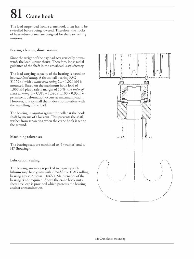
81 Crane hook
The load suspended from a crane hook often has to beswivelled before being lowered. Therefore, the hooksof heavy-duty cranes are designed for these swivellingmotions.
Bearing selection, dimensioning
Since the weight of the payload acts vertically down-ward, the load is pure thrust. Therefore, loose radialguidance of the shaft in the crosshead is satisfactory.
The load carrying capacity of the bearing is based onits static load rating. A thrust ball bearing FAG51152FP with a static load rating C0 = 1,020 kN ismounted. Based on the maximum hook load of 1,000 kN plus a safety margin of 10 %, the index ofstatic stressing fs = C0/P0 = 1,020 / 1,100 = 0.93; i. e.,permanent deformation occurs at maximum load.However, it is so small that it does not interfere withthe swivelling of the load.
The bearing is adjusted against the collar at the hookshaft by means of a locknut. This prevents the shaftwasher from separating when the crane hook is set onthe ground.
Machining tolerances
The bearing seats are machined to j6 (washer) and toH7 (housing).
Lubrication, sealing
The bearing assembly is packed to capacity with lithium soap base grease with EP additives (FAG rollingbearing grease Arcanol L186V). Maintenance of thebearing is not required. Above the crane hook nut asheet steel cap is provided which protects the bearingagainst contamination.
81: Crane hook mounting

82 Mast guidance bearings of a fork lift truck
The fork lift carriage must run smoothly in order tohandle the live loads efficiently. This requirement issatisfied by mast guide rollers and chain returnsheaves.Mast guide rollers (HMFR) and chain sheaves (KR) ofmodern fork lift trucks are largely fitted with double-row angular contact ball bearings.
Bearing selection, bearing design
Mast guide rollersFAG HMFR30x75x20.75 are preferably used for forkcarrier and lifting frame. They can accommodate radi-al loads, thrust loads and the moments resulting fromthese. The mast guide rollers feature thick-walled outerrings and can, therefore, accommodate even high,shock-type loads.The profile and dimensions of the outer ring are large-ly dictated by the standardized U-beam dimensions.
Chain sheavesChain sheaves FAG KR30x75x28/27 are attached tothe hydraulically actuated upper section of the mastand serve to deflect the pull chain.
Due to their relatively thick-walled outer ring, thebearings can accommodate high radial loads made upof the deadweight of the fork lift carriage, includingfork and live load. The outer ring profile is dictated bythe pull chain used; lateral guidance is provided by thetwo lips. The distance between the two ball rows, to-gether with the contact angle, provides for a wide spreadso that the return sheaves can also accommodate tiltingforces and axial guiding forces. Roller mounting is simple; they are simply placed onthe pin; axial preloading by a screw is not required.Chain return sheaves are axially locked.
Machining tolerances
The inner rings of der mast guide rollers and returnsheaves carry point load, thus a loose fit is satisfactory.The pin is machined to j6.
Lubrication, sealing
The bearings are lubricated for life with a lithium soapbase grease (EP additives).Sealing is provided by single- or double-lip RSR seals.
Mast guide roller Chain sheave
82: Mast guide roller and chain return sheave for a fork lift truck

83 Head pulley of a belt conveyor
One head pulley is not sufficient for very long belts,steeply inclined belts or heavily loaded belts. In suchcases several head pulleys are mounted in tandem. Inthis application, two head pulleys are arranged at thedrive station. Three identical driving motors are used:the first pulley is driven from both ends, the secondone from one end only.
With an index of dynamic stressing fL ≈ 4 the bearingsare adequately dimensioned compared to field-provenbearing arrangements. Often the bearing life is limitedby wear on rolling elements and raceways and is gener-ally shorter than the nominal rating life (approx.50,000 h), calculated with the index of dynamic stress-ing fL. Improved cleanliness during mounting and op-eration, and a suitable lubricant, reduce wear, thus in-creasing the bearing life. These influences are takeninto account in the adjusted rating life calculation bythe factor a23.
Machining tolerances
The bearing inner rings carry circumferential load.They are fitted on the shaft with adapter sleeves FAGH3264HG.Shaft to h8 and cylindricity tolerance (DIN ISO1101) IT5/2; housing bore to H7.
Lubrication, sealing
Grease lubrication with a lithium soap base grease ofpenetration class 2 with EP additives (FAG rolling bear-ing grease Arcanol L135V or L186V).
The housing covers and rings on the shaft form non-rubbing labyrinth seals. These multiple labyrinths arefilled with the same grease as the bearings and preventpenetration of foreign matter. In very dusty environ-ments relubrication at short intervals is required.Grease is injected into the bearing until some of thespent grease escapes from the labyrinths.
Operating data
Power consumption 3 x 430 kW; belt width 2,300 mm; belt speed 5.2 m/s; conveying capacity7,500 m3/h; pulley diameter 1,730 mm.
Bearing selection, dimensioning
The shaft of the head pulley is supported on plummerblocks. The shaft diameter is dictated by strength con-siderations, thus determining the bearing bore andhousing size. Spherical roller bearings FAG23264K.MB are mounted. The one-piece plummerblock housings FAG BND3264K are made of caststeel GS-45. One of the plummer blocks acts as the locating bearing, the other one as the floating bearing.To simplify mounting and dismounting hydraulicsleeves are used.

83: Head pulley bearing arrangement of a belt conveyor

Internal bearings for the tension/84 take-up pulley of a belt conveyor
Non-driven pulleys in belt conveyors are frequently fit-ted with internal bearings. The bearings are integratedinto the pulley so that the pulley body revolves aboutthe stationary shaft.
Operating data
Belt width 3,000 mm; belt speed 6 m/s; pulley diame-ter 1,000 mm; pulley load 1,650 kN.
Bearing selection, dimensioning
These pulleys are supported either in two sphericalroller bearings (fig. a) or in two cylindrical roller bear-ings (fig. b). The internal design of the cylindrical roll-er bearings allows the rolling elements to accommodateload-related shaft deflections without edge running.
In a spherical roller bearing arrangement, an FAG23276BK.MB with an adapter sleeve FAGH3276HGJ is used as locating bearing and an FAG23276B.MB is used as floating bearing.
In a cylindrical roller bearing arrangement, the floatingbearing is an FAG 547400A and the locating bearingan FAG 544975A. Both cylindrical roller bearingshave the main dimensions 360 x 680 x 240 mm andare interchangeable with spherical roller bearings FAG23276BK.MB with an adapter sleeve FAGH3276HGJ.
The bearings must feature the required dynamic loadrating C/the required bore diameter. With an index ofdynamic stressing fL > 4, the bearings are sufficiently di-mensioned with regard to fatigue life.
Often, the actual bearing life is considerably shorterthan the nominal rating life determined on the basis ofthe fL value. The cause is wear in raceways and on roll-ing elements as a result of adverse ambient conditions.Improved cleanliness during mounting and in opera-tion as well as the utilization of a suitable lubricanthave a positive effect on the bearing life. These influ-ences are taken into account in the adjusted rating lifecalculation and in the modified life calculation in accor-dance with DIN ISO 281. It is used for example tocompare the effects of different lubricants. The fatiguelife calculated for pulley bearings with this method inmost cases is not equivalent to the attainable life as theservice life is mainly limited by wear.
Machining tolerances
In view of the circumferential load and the relativelyhigh amount of load the outer rings must be a verytight fit in the pulley bore. Tolerances, see table below.
Lubrication, sealing
The bearings are lubricated with a lithium soap basegrease of penetration 2 with EP additives (FAG rollingbearing grease Arcanol L186V).
External sealing of the bearings is provided by non-rubbing labyrinth seals or multi-collar rubbing seals. Inboth cases the labyrinths are filled with the same greaseas the bearings. To supply the bearings with freshgrease and to increase the sealing effect, relubrication iseffected at short intervals (depending on the amountof dirt) via the stationary shaft.
Machining tolerances
Bearing Seat Diameter tolerance Cylindricity tolerance
Spherical roller bearing Shaft h8 IT5/2as locating bearing Pulley bore M7 IT5/2
Spherical roller bearing Shaft g6 IT5/2as floating bearing Pulley bore M7 IT5/2
Cylindrical roller bearing Shaft g6 IT5/2locating bearing, floating bearing Pulley bore N7 IT5/2

84: Internal bearings for the tension / take-up pulley of a belt conveyor
a
b
Belt conveyor idlers
Many industries use belt conveyors for transportingbulk materials. The conveyors run on idlers and mayextend over many miles; thus the number of idlersneeded may be very large. Consequently, bearingmounting design is dictated by cost-saving considera-tions.
Idler arrangement
Small belt conveyor systems feature idlers rigidlylinked to a frame. Large belt conveyor systems featureidler garlands linked to each other by flexible joints.
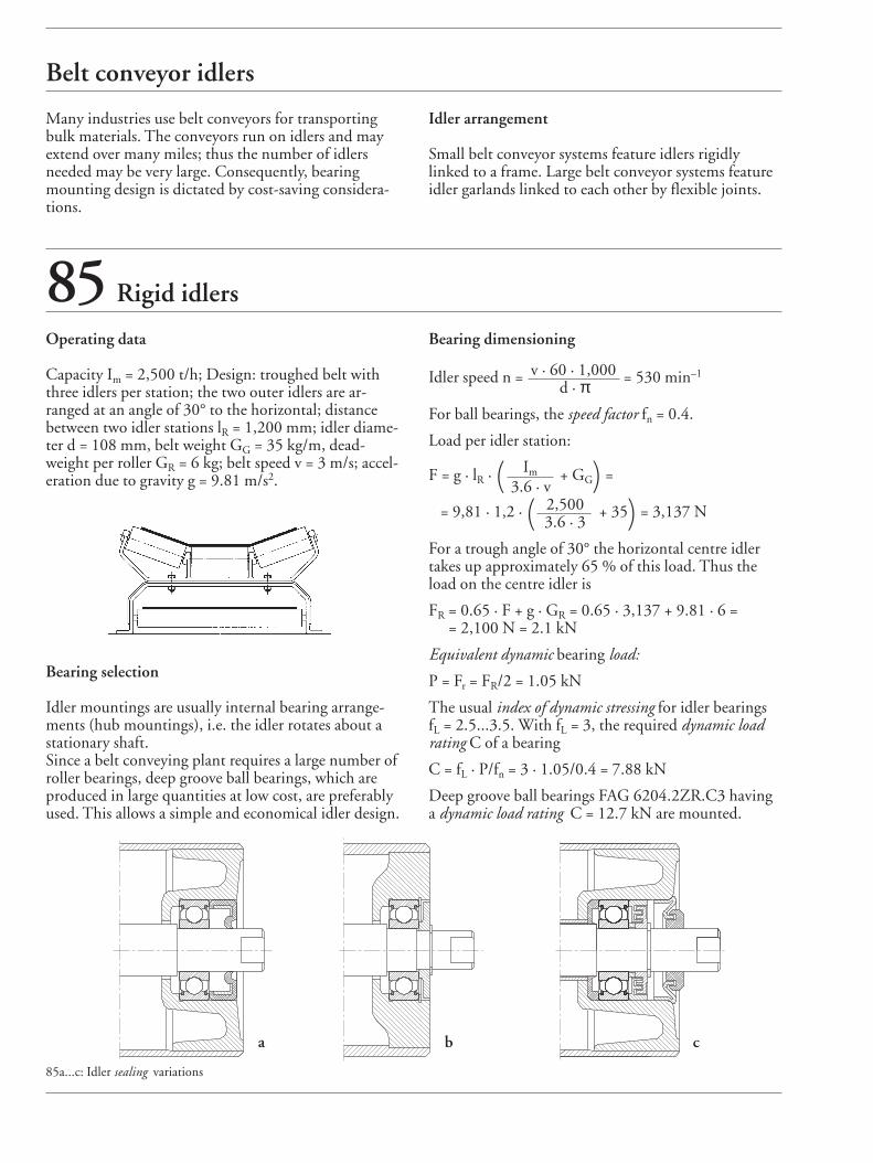
85 Rigid idlers
Operating data
Capacity Im = 2,500 t/h; Design: troughed belt withthree idlers per station; the two outer idlers are ar-ranged at an angle of 30° to the horizontal; distancebetween two idler stations lR = 1,200 mm; idler diame-ter d = 108 mm, belt weight GG = 35 kg/m, dead-weight per roller GR = 6 kg; belt speed v = 3 m/s; accel-eration due to gravity g = 9.81 m/s2.
Bearing selection
Idler mountings are usually internal bearing arrange-ments (hub mountings), i.e. the idler rotates about astationary shaft.Since a belt conveying plant requires a large number ofroller bearings, deep groove ball bearings, which areproduced in large quantities at low cost, are preferablyused. This allows a simple and economical idler design.
85a...c: Idler sealing variations
Bearing dimensioning
Idler speed n = v · 60 · 1,000 = 530 min–1
d · πFor ball bearings, the speed factor fn = 0.4.
Load per idler station:
F = g · lR · ( Im + GG) =3.6 · v
= 9,81 · 1,2 · ( 2,500 + 35) = 3,137 N3.6 · 3
For a trough angle of 30° the horizontal centre idlertakes up approximately 65 % of this load. Thus theload on the centre idler is
FR = 0.65 · F + g · GR = 0.65 · 3,137 + 9.81 · 6 = = 2,100 N = 2.1 kN
Equivalent dynamic bearing load:
P = Fr = FR/2 = 1.05 kN
The usual index of dynamic stressing for idler bearings fL = 2.5...3.5. With fL = 3, the required dynamic loadrating C of a bearing
C = fL · P/fn = 3 · 1.05/0.4 = 7.88 kN
Deep groove ball bearings FAG 6204.2ZR.C3 havinga dynamic load rating C = 12.7 kN are mounted.
a b c

86 Idler garland
Generally, the service life of a bearing is not terminatedby fatigue but by wear in raceways and on rolling ele-ments as a result of contamination. Increased cleanli-ness during mounting and efficient sealings increasethe bearing life. The ajdusted rating life calculation isused for comparing different seal designs. New idler bearings feature utmost cleanliness (V =0.3). However, in the course of operation the lubricantgets heavily contaminated by particles (V = 3).As the bearings in belt conveyor systems fail as a resultof wear, the values obtained by the adjusted rating lifecalculation (Lhna) usually are not equivalent to the actu-ally attainable lives.
Machining tolerances
The two deep groove ball bearings are mounted ontothe idler shaft in a floating bearing arrangement. As theinner rings are subjected to point load the shaft is ma-chined to h6 or js6. The outer rings are subjected tocircumferential load and are pressed, therefore, into theidler end with an M7 interference fit.
Lubrication, sealing and maintenance
The deep groove ball bearings FAG 6209.2ZR.C3 arepacked, at the manufacturing plant, with a lithiumsoap base grease of penetration class 2 which is suffi-cient for the entire bearing service life. Such a grease isalso used for the sealing.With idler bearings, both the attainable life and the lu-bricant service life may be considerably reduced bygrease contamination during operation so that the seal-ing selected is decisive. Figs. 85a...c show various typesof sealing for belt conveyor idlers.Simple seals (figs. 85a and b) are used for clean envi-ronments. Fig. 85c shows an idler seal for brown coalopen pit mining.
In addition to the rigidly troughed belt conveyors thegarland type belt conveyors are being increasinglyused. The idlers of each station are linked to each otherby flexible joints. These joints may consist of a wirerope, a chain link (flat chain, round chain), hinge orsimilar.Idler garlands accommodate impacts elastically; in theevent of problems with a roller the individual garlandis lowered and can be replaced relatively easily if neces-sary.
Fig. 86 shows idler garlands connected by chain links.These idlers are part of a conveying installation forrock phosphate. The bearings fitted are deep grooveball bearings FAG 6303.2ZR.C3.
Machining tolerances
Idler ends to M7, shaft to h6 or js6.
Lubrication, sealing, maintenance
The deep groove ball bearings (design .2ZR) are sealedby dust shields on both sides and filled with FAG roll-ing bearing grease, a lithium soap base grease of pene-tration class 2. The grease filling suffices for idler ser-vice life. A grease chamber with a non-rubbing laby-rinth seal is provided at the outboard end. The second,adjacent chamber is closed by a shield pressed into thehub bore. A baffle plate protects the bearing againstcoarse particles.
86: Idlers connected by chain link

87 Bucket wheel shaft of a bucket wheel excavator
Bucket wheel excavators are mainly used for browncoal open pit mining. The bucket wheel shaft carriesthe bucket wheel, the bull gear and the transmissionhousing. It is supported in the boom ends.
Operating data
Input power 3 x 735 kW; theoretical conveying capac-ity 130,000 m3 / day; bucket wheel speed 3 min–1.
Bearing selection
The bearings of the bucket wheel shaft are subjected tohigh shock-type loads. Moreover, shaft deflections andmisalignments must be expected. For this reason, onlyself-aligning roller bearings are suitable for supportingthe shaft. At both shaft ends, spherical roller bearingsFAG 239/900K.MB with withdrawal sleeves FAGAH39/900H are mounted as locating bearings. Ther-mal length variations of the shaft are compensated forby the elastic surrounding structure. The radial clear-ance of the spherical roller bearings is eliminated dur-ing mounting by pressing in the withdrawal sleeves.Only a split bearing can be provided on the bucketwheel side of the transmission box due to the solid forged shaft flange to which the bull gear is attached. Ifan unsplit bearing were to be provided on the oppositeside of the transmission box it could only be replacedafter dismounting the spherical roller bearing first.
For this purpose the entire bucket wheel shaft wouldhave to be removed from the boom. This is avoided byusing a split FAG cylindrical roller bearing of dimen-sions 1,000 x 1,220 x 170/100 mm on this side aswell. The increased axial clearance of the two cylindri-cal roller bearings yields a floating bearing arrangement.Each bearing accommodates axial guiding loads inonly one direction. The inner ring halves are attachedto the shaft by means of separate locking rings. Thecalculated nominal rating life of all bearings is over75,000 hours.
Machining tolerances
All inner rings are subjected to circumferential load.The spherical roller bearings FAG 239/900K.MB arehydraulically fastened to the shaft (machined to h8) bymeans of withdrawal sleeves FAG AH39/900H. Thesplit cylindrical roller bearings sit directly on the shaftwhich is machined to m6 in this place. All outer ringseats are toleranced to H7.
Lubrication, sealing
The spherical roller bearings are oil-bath lubricated.The split cylindrical roller bearings are supplied by thedraining oil from gearwheel lubrication.The sealing is a combination of labyrinth and rubbingseal. The labyrinths at the spherical roller bearings canbe relubricated.
87: Bucket wheel mounting

88 Bottom sprocket of a bucket chain dredger
Bucket chain dredgers perform dredging work in waterways. The buckets are carried by a continuouschain from the bottom sprocket to the top sprocketover a large number of support rolls and back.
shaft call for self-aligning bearings. The bearings usedare spherical roller bearings FAG 22240B.MB. Bothbottom sprocket shaft bearings are designed as locatingbearings. However, the bearings are not nipped axially,the housing being mounted with clearance in its ladderyoke seat. For easier bearing dismounting the shaftjournal is provided with oilways and grooves for hy-draulic dismounting.
Machining tolerances
Circumferential load on the inner ring.Shaft journal to m6; housing to J7.
Lubrication, sealing
The grease in the bearing (FAG rolling bearing greaseArcanol L186V) is renewed at intervals of 1 1/2 to 2years coinciding with the general overhaul period ofthe dredger. The bottom sprocket is constantly immersed in water.This requires waterproof sealing. Each bearing locationis, therefore, fitted with two rubbing seals (shaft sealswith bronze garter spring) and, in addition, with twopacking rings (stuffing box). The shaft seals run on abush of seawater-resistant material. The stuffing boxcan be retightened by means of a cover. Grease is regu-larly pumped into the labyrinth between the shaft sealsand packing rings.
Operating data
Ladder length 32 m; number of buckets 44; maximumdredging depth approximately 14 m; radial load onbottom sprocket approximately 250 kN.
Bearing selection
Rugged operation and unvoidable misalignmentbetween the housings at both ends of the sprocket
88: Bottom sprocket of a bucket chain dredger

89 Drive unit of a finished goods elevator
Finished-goods elevators are used, for example, forcharging salt granulating plants. The material is conveyed in buckets attached to a chain. The chain isdriven by the tumbler situated at the upper end.
Operating data
Input power 22 kW; speed 13.2 min–1; radial bearingload 90 kN.
Bearing selection
As shaft deflections and misalignments have to be ex-pected the drive shaft is supported on self-aligningbearings. Selecting split spherical roller bearings FAG222SM125T ensures that the heavy drive unit withthe torque arm does not have to be dismounted in theevent of repair. As a result, the downtimes of the plant and the cost ofproduction loss are considerably lower than theywould be with one-piece bearings. To limit the varietyof bearings used, a split spherical roller bearing wasprovided at the free shaft end as well.Split spherical roller bearings have a cylindrical bore.Inner ring, outer ring and cage with roller set are splitinto halves.
The split inner ring halves are braced together bymeans of four dowel screws and attached to the shaft.Both outer ring halves are fitted together without a gapby means of two dowel screws.The drive-end bearing is mounted with two locatingrings and acts as the locating bearing; the bearing at theopposite end is the floating bearing. Split spherical roll-er bearings FAG 222SM125T are designed in such away that they can be mounted into split series hous-ings FAG SNV250 instead of one-piece spherical rollerbearings with an adapter sleeve. Outside diameter, out-er ring width and shaft seat diameter are identical.The theoretical fatigue life Lh of the bearings is over100,000 hours.
Machining tolerances
Shaft to h6...h9;housing to H7
Lubrication, sealing
The bearings are lubricated with grease. The housingsare connected to a central lubricating system so thatcontinuous relubrication is ensured.The shaft openings on both sides of the housing areeach sealed by a two-lip seal.
89: Drive unit of a finished goods elevator