the design of gating system - bangladesh university of ...teacher.buet.ac.bd/bazlurrashid/mme345/lec...
TRANSCRIPT

MME 345
Lecture 16
The Design of Gating System3. Theoretical considerations in gating design
Ref:
[1] ASM Metal Handbook, Vol. 15: Casting, ASM International
[2] Taylor, Flemings, and Wulff. Foundry engineering, Wiley Eastern Limited, 1959.
Topics to discuss....
1. Introduction
2. Laws of fluid dynamics
3. Modes of liquid flow
4. Fluid dynamics in the gating system
1. Introduction
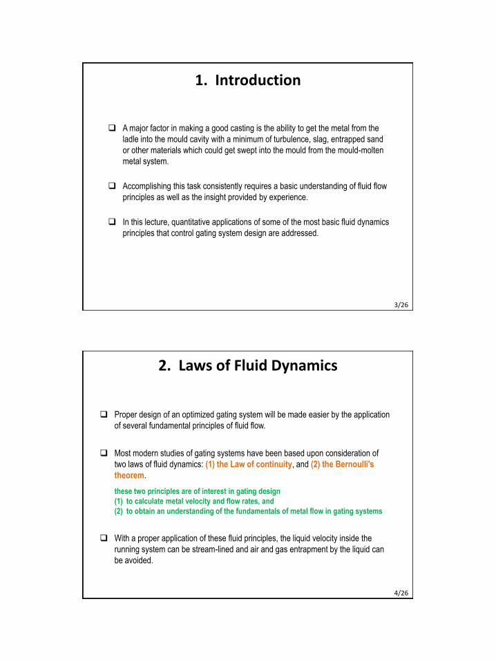
A major factor in making a good casting is the ability to get the metal from the
ladle into the mould cavity with a minimum of turbulence, slag, entrapped sand
or other materials which could get swept into the mould from the mould-molten
metal system.
Accomplishing this task consistently requires a basic understanding of fluid flow
principles as well as the insight provided by experience.
In this lecture, quantitative applications of some of the most basic fluid dynamics
principles that control gating system design are addressed.
3/26
2. Laws of Fluid Dynamics
Proper design of an optimized gating system will be made easier by the application
of several fundamental principles of fluid flow.
Most modern studies of gating systems have been based upon consideration of
two laws of fluid dynamics: (1) the Law of continuity, and (2) the Bernoulli's
theorem.
these two principles are of interest in gating design
(1) to calculate metal velocity and flow rates, and
(2) to obtain an understanding of the fundamentals of metal flow in gating systems
With a proper application of these fluid principles, the liquid velocity inside the
running system can be stream-lined and air and gas entrapment by the liquid can
be avoided.
4/26
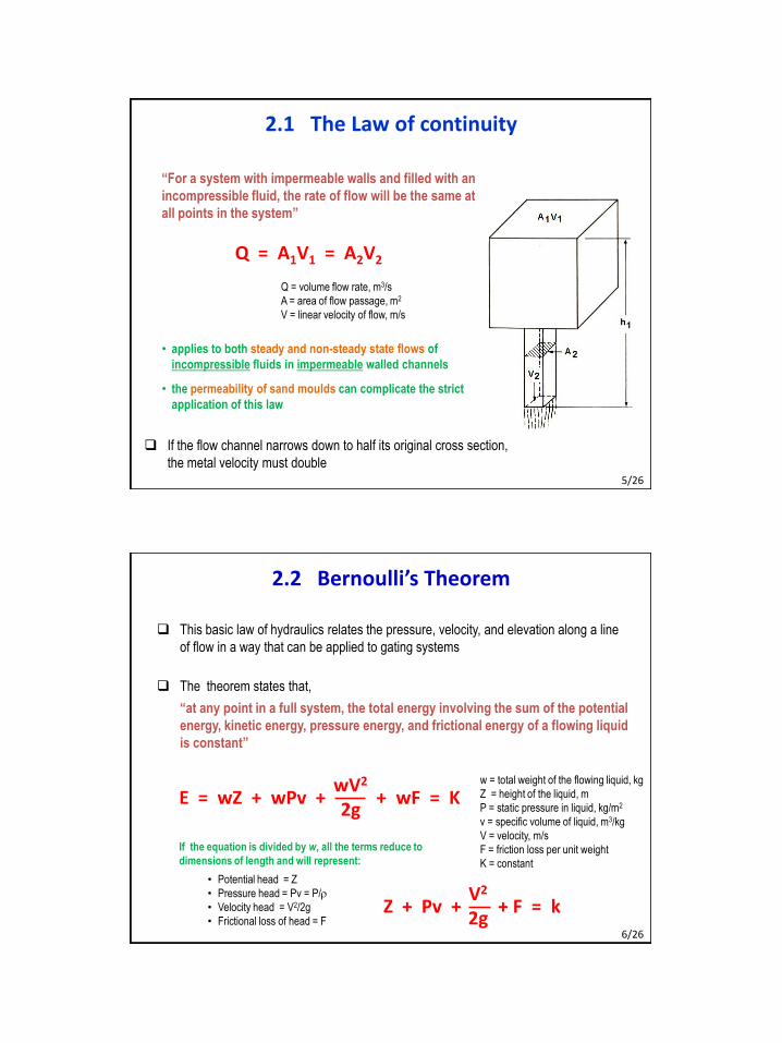
• applies to both steady and non-steady state flows of
incompressible fluids in impermeable walled channels
• the permeability of sand moulds can complicate the strict
application of this law
2.1 The Law of continuity
Q = A1V1 = A2V2
Q = volume flow rate, m3/s
A = area of flow passage, m2
V = linear velocity of flow, m/s
“For a system with impermeable walls and filled with an
incompressible fluid, the rate of flow will be the same at
all points in the system”
If the flow channel narrows down to half its original cross section,
the metal velocity must double5/26
2.2 Bernoulli’s Theorem
This basic law of hydraulics relates the pressure, velocity, and elevation along a line
of flow in a way that can be applied to gating systems
The theorem states that,
“at any point in a full system, the total energy involving the sum of the potential
energy, kinetic energy, pressure energy, and frictional energy of a flowing liquid
is constant”
E = wZ + wPv + + wF = KwV2
2g
w = total weight of the flowing liquid, kg
Z = height of the liquid, m
P = static pressure in liquid, kg/m2
v = specific volume of liquid, m3/kg
V = velocity, m/s
F = friction loss per unit weight
K = constant
If the equation is divided by w, all the terms reduce to
dimensions of length and will represent:
• Potential head = Z
• Pressure head = Pv = P/r
• Velocity head = V2/2g
• Frictional loss of head = FZ + Pv + + F = k
V2
2g6/26
The equation allows prediction of the effect of the several variables at different
points in the gating system, although several conditions inherent in foundry gating
systems complicate and modify its strict application. For example:
• The equation is for full systems, and at least at the start of pouring, a gating system
is empty. This indicates that a gating system should be designed to establish as
quickly as possible the flow conditions of a full system
• The equation assumes an impermeable wall around the flowing metal. In sand
foundry practice, the permeability of the mould medium can introduce problems,
for example, air aspiration in the flowing liquid
• Additional energy losses due to turbulence and changes in the direction of flow
at bend must be accounted for
• Heat loss from the liquid metal is not considered, which will set a limit on the time
over which flow can be maintained. Also, solidifying metal on the walls of the
gating system components will alter their design while flow continues
7/26
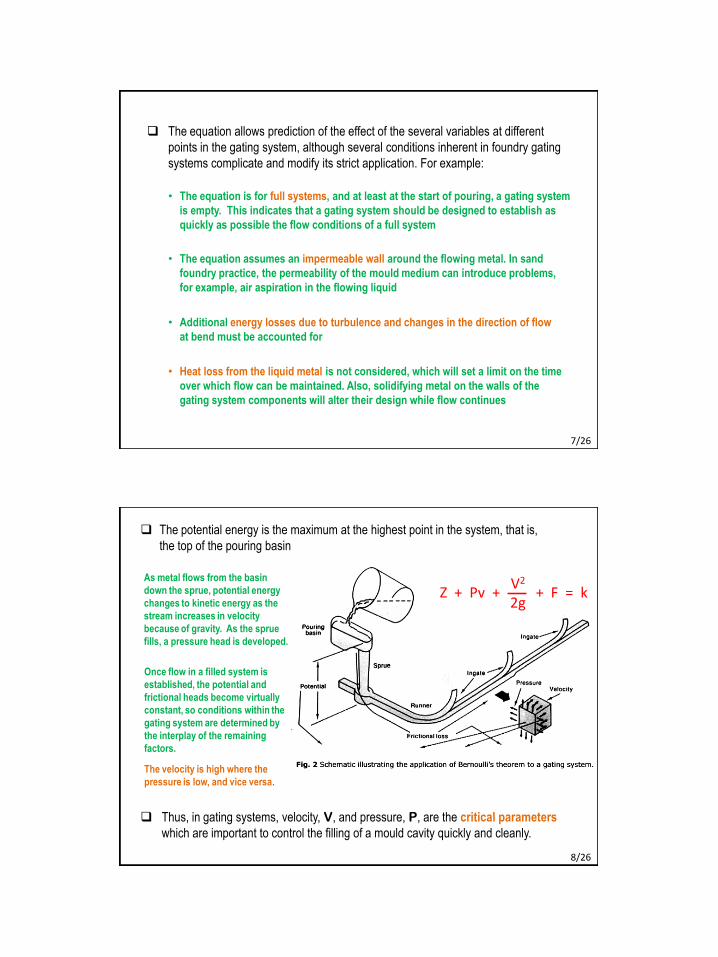
The potential energy is the maximum at the highest point in the system, that is,
the top of the pouring basin
As metal flows from the basin
down the sprue, potential energy
changes to kinetic energy as the
stream increases in velocity
because of gravity. As the sprue
fills, a pressure head is developed.
Once flow in a filled system is
established, the potential and
frictional heads become virtually
constant, so conditions within the
gating system are determined by
the interplay of the remaining
factors.
The velocity is high where the
pressure is low, and vice versa.
Thus, in gating systems, velocity, V, and pressure, P, are the critical parameters
which are important to control the filling of a mould cavity quickly and cleanly.
Z + Pv + + F = kV2
2g
8/26
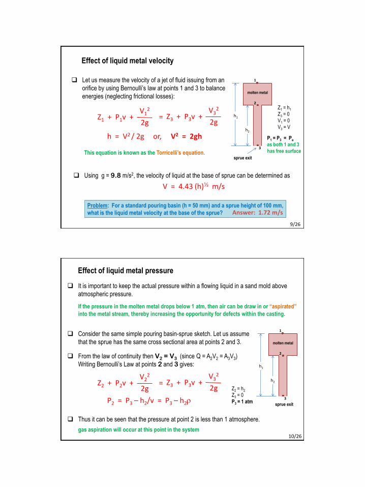
Let us measure the velocity of a jet of fluid issuing from an
orifice by using Bernoulli’s law at points 1 and 3 to balance
energies (neglecting frictional losses):
h = V2 / 2g or, V2 = 2gh
Z1 + P1v + =V1
2
2gZ3 + P3v +
V32
2g
Z1 = h1
Z3 = 0
V1 = 0
V3 = V
Using g = 9.8 m/s2, the velocity of liquid at the base of sprue can be determined as
V = 4.43 (h)½ m/s
This equation is known as the Torricelli’s equation.
Problem: For a standard pouring basin (h = 50 mm) and a sprue height of 100 mm,
what is the liquid metal velocity at the base of the sprue?
P1 = P3 = Pa
as both 1 and 3
has free surface
h1
h2
1
2
3
molten metal
sprue exit
Effect of liquid metal velocity
Answer: 1.72 m/s
9/26
It is important to keep the actual pressure within a flowing liquid in a sand mold above
atmospheric pressure.
If the pressure in the molten metal drops below 1 atm, then air can be draw in or “aspirated”
into the metal stream, thereby increasing the opportunity for defects within the casting.
Consider the same simple pouring basin-sprue sketch. Let us assume
that the sprue has the same cross sectional area at points 2 and 3.
From the law of continuity then V2 = V3 (since Q = A2V2 = A3V3)
Writing Bernoulli’s Law at points 2 and 3 gives:
P2 = P3 – h2/v = P3 – h2r
Z2 + P2v + =V2
2
2gZ3 + P3v +
V32
2g
h1
h2
1
2
3
molten metal
sprue exit
Z2 = h2
Z3 = 0
P3 = 1 atm
Thus it can be seen that the pressure at point 2 is less than 1 atmosphere.
gas aspiration will occur at this point in the system
Effect of liquid metal pressure
10/26

Shape of fallen stream in downsprue
During free fall through a long parallel channel, the liquid metal gains velocity
during descent following the law of continuity (Q = A1V1 = A2V2).
The result is the tapered shape typical of a free-falling stream shown in the Fig. (a)
Schematic showing the advantages of a
tapered sprue over a straight-sided sprue.
(a) Natural flow of free-falling liquid.
(b) Air aspiration induced by liquid flow
in a straight-sided sprue.
If the same flow is directed down a straight-sided sprue, Fig. (b), the falling stream will
create a low-pressure area as it pulls away from the sprue walls and will probably
aspirate air.
the flow will tend to be uneven and turbulent, especially when the stream reaches the base
of the sprue. 11/26
Schematic showing the advantages of
a tapered sprue over a straight-sided
sprue.
(a) Natural flow of free-falling liquid.
(b) Air aspiration induced by liquid
flow in a straight-sided sprue.
(c) Liquid flow in a tapered sprue.
The tapered sprue shown in Fig. (c) is designed to conform to the natural form of the
flowing stream and therefore reduces turbulence and the possibility of air aspiration.
It also tends to fill quickly, establishing the pressure head characteristic of the full-flow
conditions required by the Bernoulli’s equation.
This is why sprues are progressively tapered, so that the diminishing cross sectional
area compensates the increasing linear velocity of the metal to provide a constant
volume rate of flow.
12/26
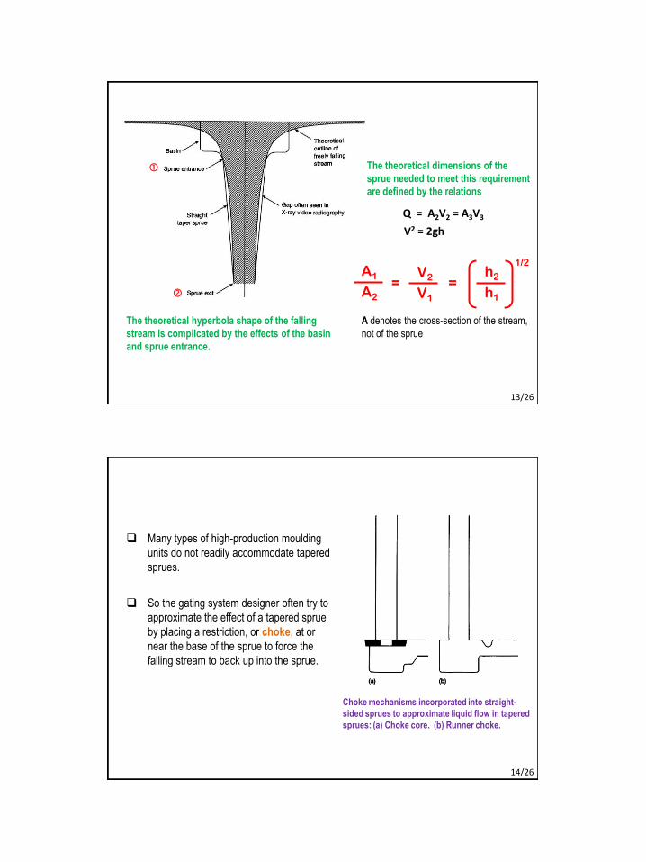
The theoretical hyperbola shape of the falling
stream is complicated by the effects of the basin
and sprue entrance.
A denotes the cross-section of the stream,
not of the sprue
Q = A2V2 = A3V3
V2 = 2gh
A1
A2
V2
V1
h2
h1
1/2
= =
The theoretical dimensions of the
sprue needed to meet this requirement
are defined by the relations
13/26
Many types of high-production moulding
units do not readily accommodate tapered
sprues.
So the gating system designer often try to
approximate the effect of a tapered sprue
by placing a restriction, or choke, at or
near the base of the sprue to force the
falling stream to back up into the sprue.
Choke mechanisms incorporated into straight-
sided sprues to approximate liquid flow in tapered
sprues: (a) Choke core. (b) Runner choke.
14/26

Laminar flow
particles move smoothly, parallel to the direction of flow
fluid velocity increases from the surface towards the centre of the channel,
where it reaches the maximum
causes the minimum frictional losses
Turbulent flow
irregular movement of the liquid particles tumbling in all directions
turbulence increases with the velocity of the stream
other factors increasing turbulent flow:
various local resistances (such as edges and sharp bends)
surface area of liquid stream that is exposed to air
any suspended second phases (inclusions, slags, gas bubbles, oxide films etc.)
entrained in the stream.
3. Modes of Liquid Flow
15/26
Reynold’s number represents the degree of turbulence
Re = (inertia force) / (viscous force)
Re = =Vd
n
rVd
m
V = mean velocity of liquid, m/s
d = linear dimension of the channel, m
r = density of liquid, kg/m3
n = kinematic viscosity of liquid = m/r
m = dynamic (absolute) viscosity of liquid, N-s/m2
Reynold’s number and critical flow velocity
16/26

(a) Re < 2000, laminar flow
(b) 2000 Re <20,000,
turbulent flow, relatively harmless so
long as the surface is not ruptured, thus
avoiding air entrainment in the flowing
stream
(c) Re 20,000
severe turbulent flow, lead to rupturing
of the stream surface with the strong
likelihood of air entrainment and dross
formation as the flowing metal reacts
with gases, and mould erosion with
consequent dirt or sand entrapment
Re = 2000 – 5000, flow starts to change from laminar to
turbulent depending on the conditions
Reynold's number, Re, and its relationship to flow characterization
17/26
Two critical flow velocities exist
• Lower critical velocity (below which flow is laminar or viscous)
• Upper critical velocity (above which the flow is turbulent)
Calculations of Re show that flow of metal in most practical gating systems is turbulent
So a certain amount of turbulence is inevitable and must therefore be tolerated
Typical critical velocity:
Al bronze and other highly oxide-prone metals 75 mm/s
Al-base and Mg-base alloys 250 mm/s
Cu-base and Fe-base alloys 500 mm/s
In practice the design of gating system
does not involve the elimination of metal turbulence,
but rather its reduction to a point where it is not harmful.
18/26
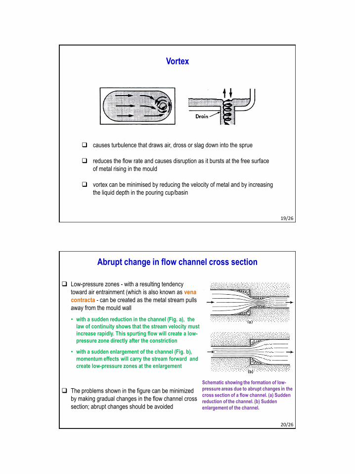
causes turbulence that draws air, dross or slag down into the sprue
reduces the flow rate and causes disruption as it bursts at the free surface
of metal rising in the mould
vortex can be minimised by reducing the velocity of metal and by increasing
the liquid depth in the pouring cup/basin
Vortex
19/26
Abrupt change in flow channel cross section
Schematic showing the formation of low-
pressure areas due to abrupt changes in the
cross section of a flow channel. (a) Sudden
reduction of the channel. (b) Sudden
enlargement of the channel.
Low-pressure zones - with a resulting tendency
toward air entrainment (which is also known as vena
contracta - can be created as the metal stream pulls
away from the mould wall
• with a sudden reduction in the channel (Fig. a), the
law of continuity shows that the stream velocity must
increase rapidly. This spurting flow will create a low-
pressure zone directly after the constriction
• with a sudden enlargement of the channel (Fig. b),
momentum effects will carry the stream forward and
create low-pressure zones at the enlargement
The problems shown in the figure can be minimized
by making gradual changes in the flow channel cross
section; abrupt changes should be avoided
20/26
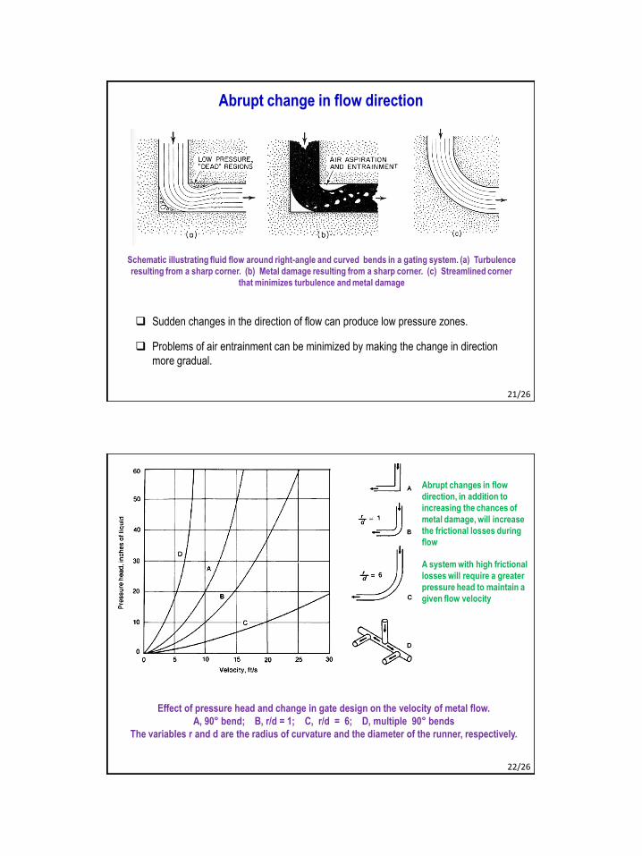
Abrupt change in flow direction
Schematic illustrating fluid flow around right-angle and curved bends in a gating system. (a) Turbulence
resulting from a sharp corner. (b) Metal damage resulting from a sharp corner. (c) Streamlined corner
that minimizes turbulence and metal damage
Sudden changes in the direction of flow can produce low pressure zones.
Problems of air entrainment can be minimized by making the change in direction
more gradual.
21/26
Effect of pressure head and change in gate design on the velocity of metal flow.
A, 90° bend; B, r/d = 1; C, r/d = 6; D, multiple 90° bends
The variables r and d are the radius of curvature and the diameter of the runner, respectively.
Abrupt changes in flow
direction, in addition to
increasing the chances of
metal damage, will increase
the frictional losses during
flow
A system with high frictional
losses will require a greater
pressure head to maintain a
given flow velocity
22/26

If the velocity is high, mould gases and air and water from moist atmosphere are
aspirated or drawn through the permeable mould into the flowing stream of metal
The quantity of gas aspirated depends upon
1. the partial pressure of gases,
2. permeability of mould, and
3. the gas pressure in the liquid
The fate of the mould gas is varied:
1. it may react with the metal, forming oxides and dross
2. dissolve in the metal to precipitate later upon freezing
3. remain in the metal as mechanically entrapped bubbles
All these possibilities are undesirable
Can be better tolerated in some metals than in others
23/26
While determining the laws of fluid dynamics, assumptions made are:
• the fluid is an incompressible liquid
• the channel is full
• the walls are impermeable
The sand moulds used for casting are:
permeable
liquid metal in the gating system is always accompanied by mould gases and air
friction at mould wall resulted
So corrections are to be applied
4. Fluid Dynamics in the Gating System
24/26

Besides, energy is lost due to
1. resistance of mould wall to the passage of metal (interface friction)
2. internal friction (viscosity) of liquid metal
3. sudden changes in cross-section
4. sharp changes in direction at bends and junctions
So corrections are to be applied using experimentally determined discharge
coefficient, although such losses are not so high.
25/26
Next ClassMME 345, Lecture 17
The Design of Gating System4. Design of gating system elements 1