mme 345 lecture 38 - bangladesh university of engineering...
TRANSCRIPT

MME 345, Lecture 38
Cast Iron Foundry Practices5. Melting and solidification of nodular iron
Ref:
[1] Heine, Loper and Rosenthal. Principles of Metal Casting, Tata McGraw-Hill, 19670
[2] J R Brown (ed.). Foseco Ferrous Foundrymen’s Handbook, Butterworth-Heninemann, 2000
Topics to discuss today …
1. Introduction
2. Classifications of ductile irons
3. Solidification process
4. Melting practices

Introduction
Developed independently in 1948 as a new engineering material by British Cast
Iron Research Association (BCIRA) and International Nickel Company (INCO)
Also known as nodular iron or spheroidal graphite iron (SGI), ductile iron is
made by treating liquid iron of suitable composition with Mg / Ce before casting
The structure consists of graphite spheroids dispersed in a steel matrix
(ferrite-pearlite structure).
graphite nodules
or spheroids
pearlite
ferrite
microstructure of pearlitic ductile ironmicrostructure of ferritic ductile iron
3/31
The only significant difference between grey iron and ductile iron is the shape
of the graphite phase; the matrix can be similar.
Because of the more spherical shape of graphite phase, the matrix of ductile
iron has the greatest effect on properties.
• unlike grey irons, the graphite phase exerts only a minor influence on the
mechanical properties
Ductile iron has the combined properties of
• grey iron: low melting point, good fluidity and castability, excellent machinability,
and good wear resistance
• steel: high strength, toughness, ductility, hot workability, and hardenability
Like steels, the steely-matrix of ductile iron can be controlled by
1. the base composition
2. the foundry practice, and
3. the heat treatment
4/31
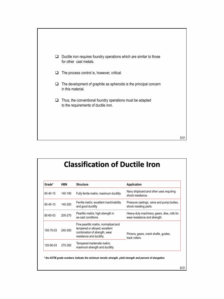
Ductile iron requires foundry operations which are similar to those
for other cast metals.
The process control is, however, critical.
The development of graphite as spheroids is the principal concern
in this material.
Thus, the conventional foundry operations must be adapted
to the requirements of ductile iron.
5/31
Classification of Ductile Iron
Grade* HBN Structure Application
60-40-15 140-190 Fully ferrite matrix; maximum ductilityNavy shipboard and other uses requiring
shock resistance.
60-45-10 140-200Ferrite matrix; excellent machinability
and good ductility
Pressure castings, valve and pump bodies,
shock resisting parts.
80-60-03 200-270Pearlitic matrix; high strength in
as-cast conditions
Heavy-duty machinery, gears, dies, rolls for
wear resistance and strength.
100-70-03 240-300
Fine pearlitic matrix, normalized and
tempered or alloyed; excellent
combination of strength, wear
resistance and ductilityPinions, gears, crank shafts, guides,
track rollers.
120-90-03 270-350Tempered martensite matrix;
maximum strength and ductility
* the ASTM grade numbers indicate the minimum tensile strength, yield strength and percent of elongation
6/31

7/31
8/31

pipe fittings
engine block
crankshaftmanhole cover
finishing rolls
some applications of ductile iron9/31
Solidification of Ductile Iron
Although similar in chemistry (with the exception of S and Mg),
ductile irons solidify in different modes than grey irons
These differences are especially pronounced in the solidification of eutectic
and are responsible for many of the processing variations
10/31

Development of Graphite Spheroids
Solidification of eutectic starts at a temperature higher than that of grey iron.
Austenite cells and graphite nodules start to grow at the expense of the liquid.
Graphite spheroids are enveloped by a shell of austenite, so that austenite only
is in contact with the liquid phase. Solidification of this type is called neoeutectic
solidification (in contrast with eutectic solidification for grey irons).
• during eutectic solidification, both austenite and graphite remain in contact with
the liquid phase
Carbon must diffuse through the solid austenite shell for the growth of spheroids.
• the process is much slower than eutectic solidification, the liquid remained for a
longer period of time, and freezing range extended to about 120 degrees
11/31
No further nucleation of spheroids occurs when the growth of neoeutectic starts.
• the number of graphite spheroids is determined at an early stage of freezing
• further cooling up to the eutectoid temperature causes the precipitation of graphite
on to the existing nodules
Subsequent cooling rate through eutectoid range and/or alloying
determines the overall matrix structure.
Obtaining adequate number of spheroid nucleation is essential to obtain a fully
nodular structure.
• if the number is low, there will be inadequate number of sites to which carbon from
liquid can diffuse
• further cooling will result either flake graphite or iron carbide depending on
composition and process variables
• both alternatives result in properties inferior to a fully nodular iron
12/31

Role of Magnesium / Cerium
Magnesium addition is the most commonly accepted method of obtaining
spheriodal graphite iron. (Other methods: Cerium, calcium, yttrium addition).
Mechanism of spheriodisation is unknown.
Well-known functions of Mg:
1. Acts as deoxdiser and desulphuriser of molten metal
2. Promotes the development of graphite as nodules
3. Prevent nucleation of graphite as flake during freezing
Actual amount of Mg required depends on S and O2 content of base iron.
Only about 0.05 % residual Mg addition is necessary for spheroid formation.
13/31
Role of Other Elements
Carbon
• Nodule count is directly proportional to carbon content
• CE value kept in excess of 4.3 (with C = 3.0–4.0 %, Si = 1.8 – 2.8 %.),
however, greater than 4.6 promotes nodule flotation and gross carbon segregation
• also improves castability by improving fluidity and feeding
Silicon
• Besides influencing nodule count and nodule flotation (by increasing CE value),
silicon addition also increases
amount of ferrite formation during eutectoid transformation, and
strength of iron by solution-strengthening the ferrite
• control of spheroidisation by adding silicon is more influencial when added late
(inoculation)
Sulphur
• increases magnesium requirement for spherodisation treatment
• sulphur content should be kept below 0.01% before spherodisation treatment14/31

The base composition of ductile cast irons usually is hypereutectic, where the carbon
and silicon contents are typically 3.7 and 2.4 respectively (CE = 4.5)
so that the first constituent to appear during solidification are graphite nodules
It is critical in making ductile iron that the amount of magnesium present in the melt
during solidification be in the range 0.03 to 0.05 weight percent.
magnesium contents less than this amount will result in graphite flakes, and amounts more than this
results in the appearance of so called exploded graphites.
either type contributes to a degradation in the ductility of the cast iron produced.
Melting Practices
15/31
The processing scheme utilized in the production of ductile iron involves
the following steps:
1. Build a charge from scrap steel, returns (risers, gates, etc.) and pig iron
2. Melt charge, desulphurise if needed, and superheat to 1535 C
3. Pour into treatment vessel, perform Mg treatment
4. Transfer into pouring ladle, inoculating with ferrosilicon
5. Pour castings
16/31

Cupola melting is the most common for the production of ductile iron
However, the need for high liquid iron temperatures and close composition control
has encouraged the use either of duplexing with an induction furnace, or using a
coreless induction furnace as prime melter.
the relation between the melting practice and they type of spherodising alloy used
is important to casting quality and physical properties
considerable reduction in amount of spherodising alloy and defective and inferior
casting can be realised by paying special attention to the charge material, melting
methods and control, and iron composition.
17/31
Acid Cupola Melting
• Used when both grey and ductile iron are produced using the same cupola.
• Acid melting is almost 5 times less costly than basic melting.
• Sulphur can not be reduced; high-quality charge (containing low S) is required.
• If low-cost charge used, desulphurization needed before Mg treatment and inoculation.
• More oxidising process than basic cupola;
reduce or control over more oxidising element (e.g., Cr, Mn) is possible
• Moderate C pick up occurs
• Close composition control and high metal temperature possible
Basic Cupola Melting
• Sulphur removal possible due to use of basic lining; desulphurization treatment not required.
• S level reduced to the acceptable limit (0.025 – 0.035%) for Mg treatment
• High Si loss, greater C pick up, less effective temperature and composition control.
• High operating cost; lining-less and hot-blast cupolas preferred for melting
18/31

Induction furnace melting
• Low-frequency, 60-cycle type furnace used
Typical process include:
Charge foundry returns, steel scrap, ferrosilicon and carburiser to achieve the desired composition
If sulphur is below 0.025%, desulphurisation is not necessary, but the higher the sulphur content,
the more Mg must be used so the cost of treatment increases
Treat with Mg and inoculate
Cast
• Extreme close control of composition and temperature possible
Cupola melting and duplexing
• The process may be summarised as follows:
Melt in acid cupola, charge foundry returns and steel scrap plus low sulphur pig iron if necessary.
If magnesium treatment with MgFeSi alloy is used, a low Si base iron is needed.
Tap at around 2.8–3.2%C, 0.6–1.0%Si, 0.08–0.12%S
Desulphurise with calcium carbide to about 0.10%S, carburise to 3.6–3.8%C
Transfer to induction furnace, adjust C and Si and temperature to required levels
Treat with MgFeSi and inoculate
Cast19/31
Presence of high S in the melt causes the loss of Mg before spherodisation can occur
for MgS formation, 0.1% S requires 0.076% Mg
Injection of fine calcium carbide using N2 gas into the melt (in the forehearth or ladle)
can reduce S level from 0.12 to 0.02 with an efficiency ~15%. The CaS floats to the
liquid surface and can be removed easily.
Addition of soda ash (Na2CO3) reduces S from 0.14 to 0.06%.
a second soda ash addition reduces S to 0.030-0.025%.
Use of lime (CaO) for desulphurisation, with or without other materials, is also used.
Desulphurisation
20/31
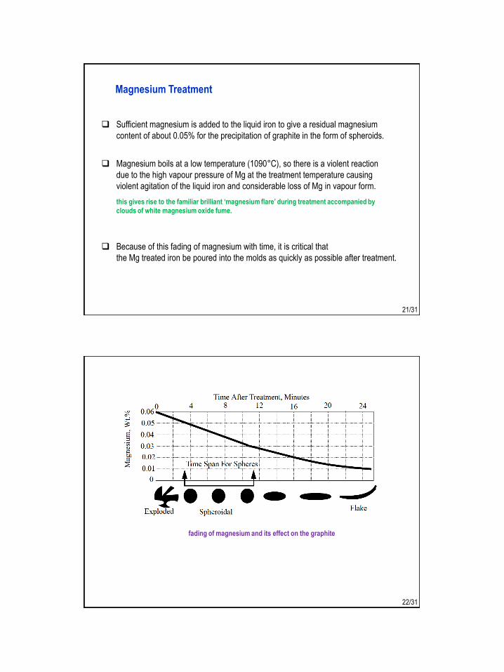
Magnesium Treatment
Sufficient magnesium is added to the liquid iron to give a residual magnesium
content of about 0.05% for the precipitation of graphite in the form of spheroids.
Magnesium boils at a low temperature (1090°C), so there is a violent reaction
due to the high vapour pressure of Mg at the treatment temperature causing
violent agitation of the liquid iron and considerable loss of Mg in vapour form.
this gives rise to the familiar brilliant ‘magnesium flare’ during treatment accompanied by
clouds of white magnesium oxide fume.
Because of this fading of magnesium with time, it is critical that
the Mg treated iron be poured into the molds as quickly as possible after treatment.
21/31
fading of magnesium and its effect on the graphite
22/31

Magnesium recovery depends on
• depth of liquid iron through which the vapour rises before entering to the atmosphere
• liquid temperature (high liquid temperature cause more Mg loss), and
• particular treatment process used.
A measure of the true Mg recovery of the treatment process can be expressed as:
23/31
Types of nodulants
Magnesium may be added as pure Mg, or as an alloy, usually Mg–ferrosilicon
or nickel–magnesium
MgFeSi alloys usually also contain 0.3–1.0% cerium accompanied by other rare
earth elements. 0.5–1.0%Ca is also a common addition to the treatment alloy.
24/31
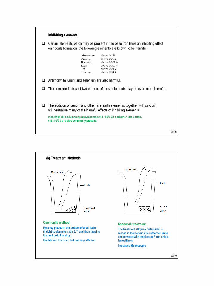
Inhibiting elements
Certain elements which may be present in the base iron have an inhibiting effect
on nodule formation, the following elements are known to be harmful:
Antimony, tellurium and selenium are also harmful.
The combined effect of two or more of these elements may be even more harmful.
The addition of cerium and other rare earth elements, together with calcium
will neutralise many of the harmful effects of inhibiting elements
most MgFeSi nodularising alloys contain 0.3–1.0% Ce and other rare earths.
0.5–1.0% Ca is also commonly present.
25/31
Mg Treatment Methods
Sandwich treatment
The treatment alloy is contained in a
recess in the bottom of a rather tall ladle
and covered with steel scrap / iron chips /
ferrosilicon;
increased Mg recovery
Open-ladle method
Mg alloy placed in the bottom of a tall ladle
(height-to-diameter ratio 2:1) and then tapping
the melt onto the alloy;
flexible and low cost; but not very efficient
26/31

Tundish cover
A specially designed cover for the
ladle improves Mg recovery and
almost eliminates glare and fume
Plunger method
The alloy is plunged into the ladle using a
refractory plunger bell; usually combined
with a ladle cover and fume extraction;
higher Mg recovery than open-ladle methods
27/31
In-mold treatment
MgFeSi alloy is placed in a chamber moulded
into the running system, the iron is continuously
treated as it flows over the alloy
Cored-wire treatment
Wire containing Mg, FeSi, Ca is fed
mechanically into liquid metal in a
covered treatment ladle at a special
station
28/31
Inoculation Treatment
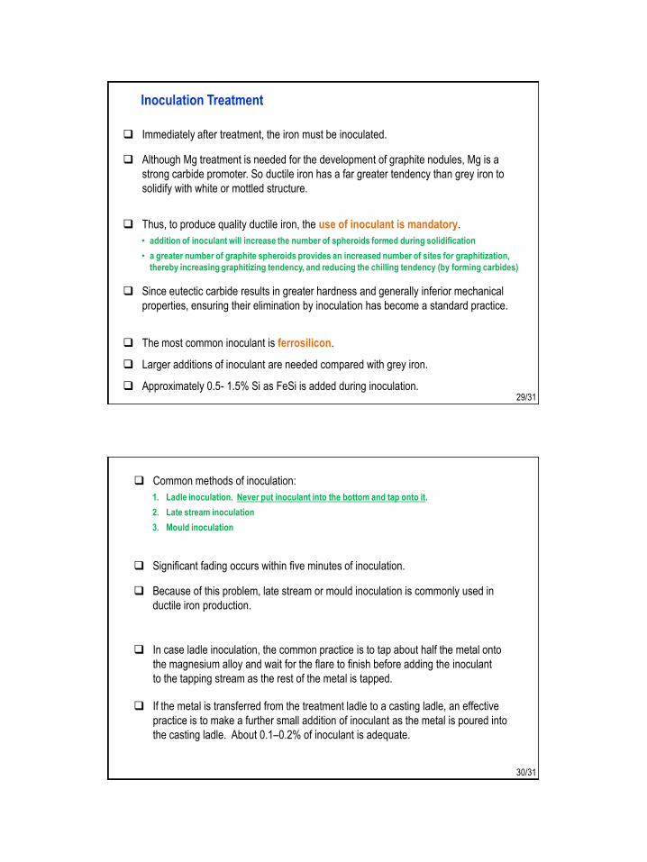
Immediately after treatment, the iron must be inoculated.
Although Mg treatment is needed for the development of graphite nodules, Mg is a
strong carbide promoter. So ductile iron has a far greater tendency than grey iron to
solidify with white or mottled structure.
The most common inoculant is ferrosilicon.
Larger additions of inoculant are needed compared with grey iron.
Approximately 0.5- 1.5% Si as FeSi is added during inoculation.
Thus, to produce quality ductile iron, the use of inoculant is mandatory.
• addition of inoculant will increase the number of spheroids formed during solidification
• a greater number of graphite spheroids provides an increased number of sites for graphitization,
thereby increasing graphitizing tendency, and reducing the chilling tendency (by forming carbides)
Since eutectic carbide results in greater hardness and generally inferior mechanical
properties, ensuring their elimination by inoculation has become a standard practice.
29/31
Common methods of inoculation:
1. Ladle inoculation. Never put inoculant into the bottom and tap onto it.
2. Late stream inoculation
3. Mould inoculation
In case ladle inoculation, the common practice is to tap about half the metal onto
the magnesium alloy and wait for the flare to finish before adding the inoculant
to the tapping stream as the rest of the metal is tapped.
If the metal is transferred from the treatment ladle to a casting ladle, an effective
practice is to make a further small addition of inoculant as the metal is poured into
the casting ladle. About 0.1–0.2% of inoculant is adequate.
Significant fading occurs within five minutes of inoculation.
Because of this problem, late stream or mould inoculation is commonly used in
ductile iron production.
30/31
Next ClassMME 345, Lecture 39
Cast Iron Foundry Practices6. Process control in nodular iron making