the corliss engine - archive.org
TRANSCRIPT


THE CORLISS ENGINE.By JOHN T^HENTHORN.
Management of the Corliss Engine
By CHARLES D. THURBER.
Uniform in One Volume ; Price, $1.00.
PR 13 1891'
EGBERT P. WATSON. //rv
This work is a republication of two articles which werefirst published in The Engineer, New York. They
are wholly practical in character, being
r intended as a guide to the most
if economical management of^^i 1
j the Corliss Engine.
COPYRIGHT BY EGBERT P. WATSON & SON, APRIL, 1891.
150 Nassau St., N. Y.
<s

T^ 4-S5"
05 H
A^fe

TABLE OF CONTENTS.
Chapter I.—Introductory and Historical. Steam
Jacketing
Chapter II.—Indicator Cards 8
Chapter III.—Indicator Cards continued. TheGovernor 14
Chapter IV.—Valve Gear and Eccentric. Valve
Setting 18
Chapter V.—Valve Setting continued, with dia-
grams of same. Table for Laps of Steam Valve. 20
Chapter VI.—Valve Setting continued 27
Chapter VII.—Lubrication, with diagrams for same 30
Chapter VIII.—Discussion of the Air Pump and its
Management 36
Chapter IX.—Care of Main Driving Gears. Best
Lubricator for same 39Chapter X.—Heating of Mills by Exhaust Steam . . 44
Chapter XI.—Engine Foundations ; diagrams and
templets for same 48
Chapter XII.—Foundations continued. Materials
for same 53

THE CORLISS ENGINE.
CHAPTER I.
Since the issue of the patent, in the year
1849, to Geo. H. Corliss, for certain improve-
ments in the working of steam-engines, and
covering the admission of steam to the cylin-
der by the combined action of a governor, to
determine the point of cut-off at which a lib-
erating valve-gear shall act, and thus allow a
certain amount of expansion to take place in
the cylinder before the end of a stroke is com-pleted, I think it will be conceded by all fair-
minded engineers, when we come to look
over the ground carefully, covered by the
proposition, that no improvement has been
made since that time, up to this date, in the
economy of working steam expansively as ex-
emplified by this system. This assumption
may be questioned even now by a few zealous
persons.
The gradual development and appreciation
of the Corliss system during the past thirty-six

years, has grown to such proportions as to
trace this Corliss principle in the design and
build of a large proportion of the engines used
in our manufacturing industries in this and
foreign countries, and I may say that its use
for maritime purposes is better appreciated to-
day, and will be still better in years to come,
by the few years of experience that it has
been subjected to to determine its value over
other systems now in use for that purpose.
During this long period of increasing useful-
ness, it has seen the rise and fall of the most
sanguine expectations of many inventors for
its honors. Sufficient evidence has been gath-
ered by steam-users throughout, I may say,
the civilized world, as a criterion of its merits ;
and this has been established by facts cover-
ing economical performance for years, rather
than by claims based upon theory.
STEAM-JACKETING.
When we consider the value that steam
-
jacketing the cylinders of an engine offers for
economizing fuel, we enter into many prob-
lems of an interesting character. The merefact of steam-jacketing a cylinder, or, in other
words, subjecting the working barrel to a con-

stant circulation of steam direct from the
boiler, inclosed in a separate chamber, does
not imply a direct or definite saving in fuel
equally available to all types of engines.
In one case it is an improvement of a very
decided character, while for another, working
under a different range of expansion, the addi-
tional expense for its provision would not be
justifiable when we consider the question of
fuel and care necessary for the proper working
condition of the jacket. Steam-jacketing is a
decided advantage when a liberal amount of
expansion is carried out in the cylinder, or
when a wide range in temperature exists be-
tween the initial temperature of the steam ad-
mitted and the final temperature at which it is
exhausted into the condenser or atmosphere.
Therefore its economical application is gov-
erned entirely by these two elements.
To steam-jacket a slide-valve engine, whenthe steam is allowed to follow nearly full
stroke before cutting off, the saving in fuel, for
this case, would not pay the difference for the
extra cost of such practice, and is not advisable.
The shorter the cut-off in any engine, the
more efficient a system of steam-jacketing the

cylinder becomes ; from the fact that the
amount of cylinder condensation which takes
place at each admission of steam to the cylin-
der is reduced to a minimum, by maintaining
the walls of the cylinder at a uniform temper-
ature.
Many people suppose that this question of
admitting steam to a cylinder to overcome a
given amount of resistance is like unto meas-
uring beans in a bushel, and of a practically
definite quantity, whereas, the fact is, that
when steam is admitted to the cylinder suffi-
cient heat has to be imparted by such entering
steam to the walls of the cylinder to bring its
temperature up to a point equal to that of the
entering steam, resulting in a possible amount of
cylinder condensation equal in quantity to that
required to overcome the work of that stroke.
It is therefore essential that when we con-
sider the question of the economical perform-
ance of any proposed engine, we thoroughly
consider the effect that an efficient system of
steam-jacketing offers for that purpose. Its
application is well worthy of the object, and
may safely be stated to save, for engines of
approved character using steam expansively,

from 8 to 10 per cent, of the fuel used. It
may be claimed by a few that the speed of
the engine has a marked influence upon the
amount of cylinder condensation, from the
theory that the walls of the cylinder are ex-
posed for a greater length of time between each
alternate stroke of the engine, for strokes of 5
to 6 feet, and about 60 revolutions per minute,
and consequently more condensation takes
place during that period than would otherwise
occur for a higher speed of rotation and shorter
stroke. This assumption, although existing as
a fact for slow speeds, ceases to have muchimportance for what may be termed long-stroke
stationary engines, say from 5 to 6 feet, or
considering other circumstances of equally
practical moment for speeds even as low as 50
to 60 revolutions per minute.
At this speed, I believe, for equal points of
cut-off or range of expansion, that the differ-
ence in fuel, due to cylinder condensation be-
tween this speed, of say 55 revolutions per
minute, and for engines of a higher speed of
rotation, say 100 revolutions per minute, a
jacket is of no practical value, as I believe, for
the disadvantages attending such a high speed

8
of engine more than neutralize any benefit to
be derived from an assumed decrease in the
cylinder condensation in the working of the
two systems.
CHAPTER II.
INDICATOR-CARDS.
I do not consider that the engine making the
finest-looking indicaior-card, as that term is
generally considered to-day by engineers, is
•necessarily working to the best advantage, re-
garding friction and economy.
I am aware that this impression has been
given by some engineers, who have suggested
to manufacturers that such must necessarily be
the case under all circumstances. I am free to
admit that I think there are other conditions to
be fulfilled, in the satisfactory working of an
engine, equally as important as giving an indi-
cator-card : "fulfilling all the conditions neces-
sary for economy " with their square corners,
excessive compression, and plumb-line induc-
tion, representing the admission of steam to
the cylinder.
To my eye, the best-looking card is that show-
ing the least amount of fiictional resistance to

be overcome for a given amount of work per-
formed, and compression sufficient to gently
affect the moving parts as they come to rest; to
turn the center with an expansion-line follow-
ing well-established rules, and.a movement of
the exhaust-valves to allow in the least possible
time, during the first part of the return stroke,
the piston to have the full benefit of the vacuumwhere a condensing-engine is employed.
If these conditions are fulfilled, I believe that
the engine is accomplishing good work eco-
nomically, with a minimum amount of friction
for the power developed. All these conditions
may be obtained, notwithstanding we mayhave a card where the steam-line falls off as in
Fig. i. To some, this may seem a very serious
delect. If we wish to drive machinery econom-ically, assuming we have tools to do it with, weshould so adjust its condition of working that it
may be able to produce that result with as little
effort to move itself as possible. This implies
an admission of fullboiler pressure to the cylin-
der after the crank has passed the center to help
turn the crank-shaft rather than retard it. This
will be the case if we attempt to make a per-
fectly plumb steam-admission line on the card.

10
To bring about this early admission of steam,
or steam-lead so called, to produce a steam-ad-
mission line at right angles to the line of mo-tion it is necessary to so place the eccentrics
relative to the crank as to have the steam-
valves which are operated by it in such a posi-
tion that boiler pressure may be upon the
Fig. i.
piston the instant the direction of motion is
changed. To accomplish this implies an open-
ing ot the steam-valve before the crank comes
up to the center, as shown in Fig. 2. Now anysuch steam pressure admitted to the cylinder
with the crank in that position is a detriment,
causing an increase in the friction of the en-

Fig. 2.
12
gine by a longer application of pressure uponcrank and cross-head pins, and main bearing
;
also, a diminution in the energy of the wheel,
which, necessarily, has to be restored by addi-
tional steam at the next stroke of the engine,
and a generally debilitating effect upon all
parts of the engine.
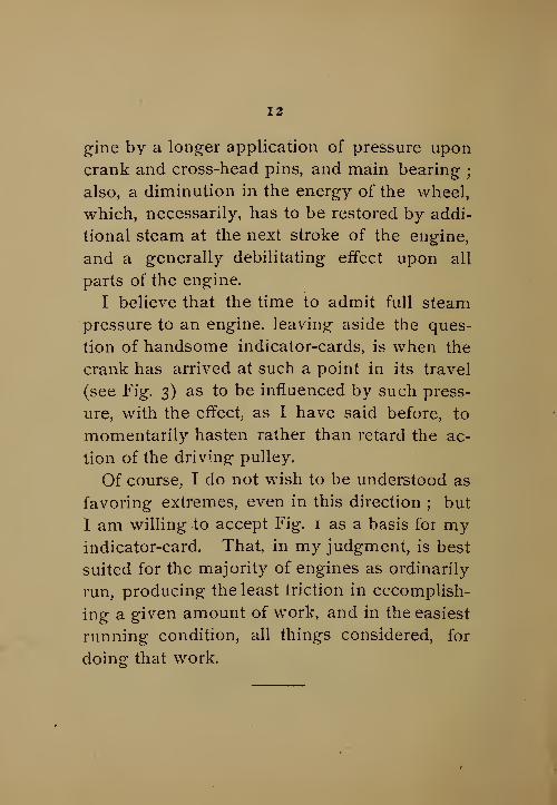
I believe that the time to admit full steam
pressure to an engine, leaving aside the ques-
tion of handsome indicator-cards, is when the
crank has arrived at such a point in its travel
(see Fig. 3) as to be influenced by such press-
ure, with the effect, as I have said before, to
momentarily hasten rather than retard the ac-
tion of the driving pulley.
Of course, I do not wish to be understood as
favoring extremes, even in this direction ; but
I am willing to accept Fig. 1 as a basis for myindicator-card. That, in my judgment, is best
suited for the majority of engines as ordinarily
run, producing the least triction in cccomplish-
ing a given amount of work, and in the easiest
running condition, all things considered, for
doing that work.

Fig. 3.

14
CHAPTER III.
I have seen, a great many times, the folly
and evil effect of allowing a fine-looking indi-
cator-card to be the ruling spirit governing
valve adjustments, where questions of a prac-
tical character have not been considered af
sufficient importance to justify thought, so
Fig. 4.
long as a "fine-looking " card, as shown in Fig.
4, is obtained. This state of affairs requires
adjustment, so that the engine may show an
indicator-card worthy of consideration, and be
given a chance to do its work, untrammeled
by steam-lead or the excessive compression
that is now "fashionable." High compression
is assumed to be a necessity for all high-speed
i5
engines, from the fact that it is much used in
locomotives.
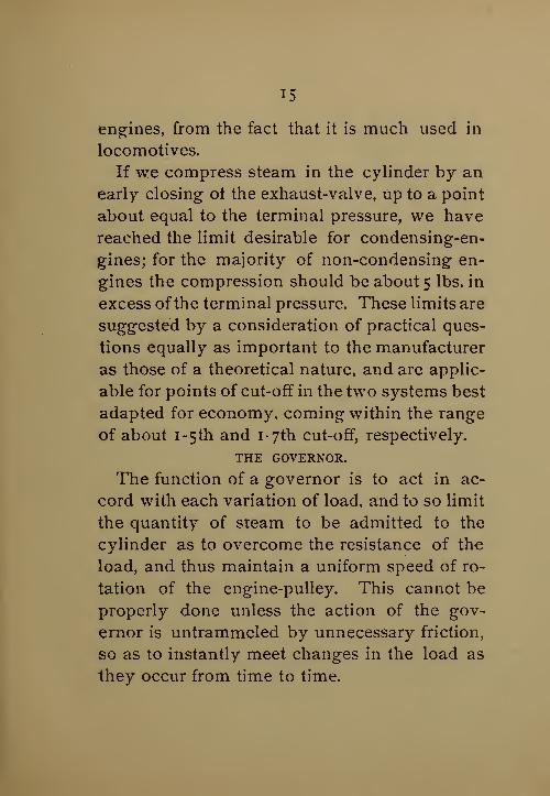
If we compress steam in the cylinder by an
early closing ot the exhaust-valve, up to a point
about equal to the terminal pressure, we have
reached the limit desirable for condensing-en-
gines; for the majority of non-condensing en-
gines the compression should be about 5 lbs. in
excess of the terminal pressure. These limits are
suggested by a consideration of practical ques-
tions equally as important to the manufacturer
as those of a theoretical nature, and are applic-
able for points of cut-off in the two systems best
adapted for economy, coming within the range
of about i-5th and i-7th cut-off, respectively.
THE GOVERNOR.
The function of a governor is to act in ac-
cord with each variation of load, and to so limit
the quantity of steam to be admitted to the
cylinder as to overcome the resistance of the
load, and thus maintain a uniform speed of ro-
tation of the engine-pulley. This cannot be
properly done unless the action of the gov-
ernor is untrammeled by unnecessary friction,
so as to instantly meet changes in the load as
they occur from time to time.

i6
We should, therefore, see that all of the
working surfaces of the governor are in proper
running condition, and a quality of oil used
for lubrication that will not " gum up" after it
has been applied for a time. We should, also,
see that the oil, or dash-pot, is in good work-
ing order, with a constant supply of oil to gent-
ly retard any sudden fluctuation in the move-
ment of the regulator.
On engines that have been speeded up to re-
lieve their working, and bring about an earlier
cut-off (by reason of an overgrown mill), wemay possibly find that the speed of the regu-
lator has been allowed to remain the same as
before the change, with a possible chance for
the overseer of weaving to suggest that the
speed is not quite so uniform as before the en-
gine was speeded up.
To anticipate any such complaint we should,
while we are changing the speed of engine,
change also that of the regulator, and to over-
come the effect of a higher speed of rotation
upon the elevation of the balls of the regulator
(and its equivalent effect upon the point of cut-
off), we should weight the regulator down (as
shown in Fig. 5) until the requisite speed is at-

17
Fig. 5,
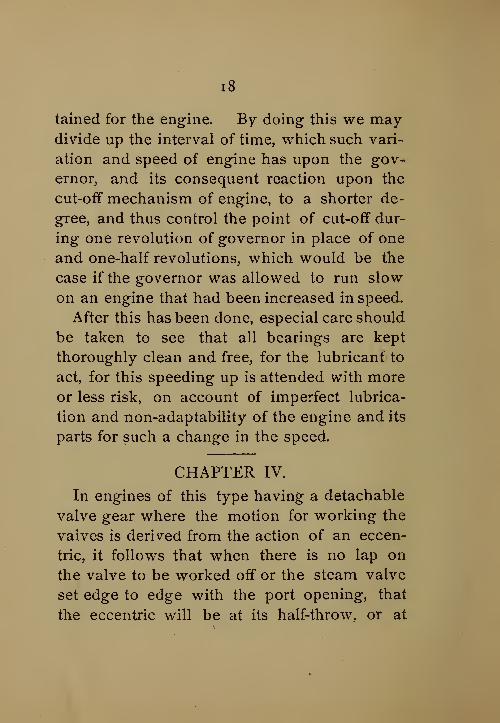
i8
tained for the engine. By doing- this we may-
divide up the interval of time, which such vari-
ation and speed of engine has upon the gov-
ernor, and its consequent reaction upon the
cut-off mechanism of engine, to a shorter de-
gree, and thus control the point of cut-off dur-
ing one revolution of governor in place of one
and one-half revolutions, which would be the
case if the governor was allowed to run slow
on an engine that had been increased in speed.
After this has been done, especial care should
be taken to see that all bearings are kept
thoroughly clean and free, for the lubricant to
act, for this speeding up is attended with moreor less risk, on account of imperfect lubrica-
tion and non-adaptability of the engine and its
parts for such a change in the speed.
CHAPTER IV.
In engines of this type having a detachable
valve gear where the motion for working the
valves is derived from the action of an eccen-
tric, it follows that when there is no lap on
the valve to be worked off or the steam valve
set edge to edge with the port opening, that
the eccentric will be at its half-throw, or at

19
right angles to that of the crank when it is on
its center.
During the rotation of the shaft, the eccen-
tric would therefore arrive at its greatest throw
and the opening motion of the steam valve
would cease, and thus the detaching mechan-
ism remain inoperative, while the crank or
piston reaches, practically embraces, half stroke,
and any liberation of the cut-off gear actuated
by the governor or other means must take
place, if at all, before this point is reached in
crank travel, or before the eccentric com-mences its return stroke. If this action has
not taken place the steam valve then com-mences to close positively at a speed governed
by that of the eccentric. In order to have a
safe working lap of the steam valve before the
exhaust port upon that end is open to atmo-
spheric pressure, or the condenser, and thus
* prevent any blowing through during the rela-
lative time of closing the steam and opening
the exhaust valves, it is essential that the valves
admitting steam to the engine should be given
a definite advance in their movement relative
to that of the exhaust.
This is commonly called lap ; this and the

20
amount of it increases with the size of the en-
gine. To neutralize this effect upon admission
of steam to the engine, and have the valve
gear in readiness to act for that purpose, whenthe crank comes up to the center, it is evident
that the position of the eccentric must be morethan 90 with relation to the crank ; or at
a position beyond its center of half throw, in
order to remove the lap given to the steam
valve, and to take a position to admit steam to
the cylinder. This ot course, reduces the range
of expansion that steam may be carried for
that end of the cylinder, by allowing less time
during the travel of the eccentric before it
reaches its full throw for the cut-off to act,
which must occur, in this case, before half
stroke is reached, or upon the opening motion
of the steam valve. Occasionally, we maysee an indicator card where the cut-off had ap-
parently taken place after more than half stroke
of the engine had been covered, which is a
very bad condition, however, considered
economically. At this point in the piston
travel the velocity is at its maximum, while that
of the valve-gear, actuated by the eccentric
nearing its dead point of full travel, is at its

21
minimum. These elements, while working,
as a matter of fact, with a positive ratio of ac-
tion to one another, admit at this high velocity
a certain amount of piston travel to take place
after the point of detachment has been reached
by the valve-gear before motion can be im-
parted to the valve and its connection sufficient
to cover a full port, and prevent further ad-
mission of steam to the cylinder. This ap-
parent cut-off taking place after half stroke has
been reached is more prominently defined on
the card as we increase the lap of the steam
valve, and, by increasing this lap we are en-
abled to open the exhaust valve sooner for the
return stroke, thus giving a free opening for
the exhaust in relation to the former, and nec-
essarily enforcing a later closing of the valve,
reducing the amount of compression; this maybe considered by a few objectionable, and wewill have something to say further on about it.
CHAPTER V.
SETTING VALVES.
Upon the wrist-plate of the engine will be
found three marks ; one representing the posi-
tion at half-travel, or center of motion, while

22
the remaining two represent the extreme mo-tion of the wrist-plate as actuated by the ec-
centric.
Upon the wrist- plate stand, or pin, as the
case may be, will be found a mark coinciding
with those on the wrist-plate, designating the
extreme motion and center of motion or travel,
Fig. 6.
as per Fig. 6. These are to be our guides in
arranging for the relative time of action be-
tween the four valves.
Upon removing the back bonnets from our
engine we shall see, also, a mark upon each
face of the valve-port, showing the location
and width of port openings in relation to the
cylinder ; thus furnishing a starting point for
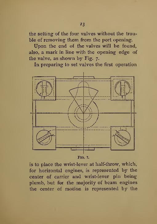
23
the setting of the four valves without the trou-
ble of removing them from the port opening.
Upon the end of the valves will be found,
also, a mark in line with the opening edge of
the valve, as shown by Fig. 7.
In preparing to set valves the first operation
UA1 *".
1 \ \
Fig. 7.
is to place the wrist-lever at half-throw, which,
for horizontal engines, is represented by the
center of carrier and wrist-lever pin being
plumb, but for the majority of beam engines
the center of motion is represented by the
24
dotted and circular marks, as indicated uponFig. 6.
At this position, designated above, the markson the wrist-lever and pin should correspond,
and the whole mechanism be secured in that
position, by placing pieces of paper between
the washer on the end of the pin and wrist-
lever, so as to produce friction sufficient to
hold the whole in the desired position whenthe nut on the end of the pin is screwed up.
This being accomplished, we may consult
the annexed table giving the lap of the steam-
valve, and the relative position of exhaust-
valve when the wrist-lever is at its center of
motion, and thus fix upon the lap for the
steam-valve and the position of exhaust-valve
desirable for the size of engine under consider-
ation.
By lengthening or shortening the connec-
tions leading from this wrist-lever to steam-
lever wTe bring the position of the opening
edge of the steam-valve to correspond with the
amount of lap fixed for that case, which, of
course, should be the same for each end of the
cylinder.
For the position of the exhaust-valve, by con-

suiting the table herewith we find for a 20" en-
gine xVth of an inch opening.
Table I.
POSITION OF STEAM AND EXHAUST-VALVES WITH WRIST-LEVER AT ITS CENTRE OF MOTION.
Size Laps of Exhaust
of engine. steam valve. valve open.
12" 41 //
3214" 5 "
T61 II
3216" 5 "
161 /'
3218" 3/'
81 //
To20" 3//
81 11
T622" 3/'
81 //
16
24" 7 "Te ft"
26" 7 "T6
3 '/
32.28" 7 "
T6 3230" 1//
21"8
32" 1"2
1'/8
34" 1"2
1//8
36" 1"2 *"
38" 9 "T6 A"
40" 9 "T6
3 II
T642" 9 "
T«3 //
16
This amount for each end of the cylinder is
obtained by lengthening or shortening of the
connection leading from wrist-lever to exhaust-
arm, while the wrist-lever still remains at its
center of motion, until we bring the marks on
the end of the exhaust-valve to the distance re-
quired from the closing edge of the exhaust-
port.

26
We have now established the relative time
desirable for the opening of the steam, andclosing of the exhaust-valves, that each should
act relatively to one another, and they should
remain so without further adjustment being
allowed upon the steam or exhaust connections
until sufficient reason is established by practi-
cal working to warrant a modification in ad-
justment, and then only upon a full considera-
tion of all the facts attending the working and
the service for which the engine is used. Whenwe change any one of these connections wealter its time of movement, and destroy the
unison of action between the closing of one
valve and the opening of another. If weshorten one steam connection, the effect is to
allow that end to open quicker than its neigh-
bor, but at the expense of a reduction in the
safe working lap that it should have with rela-
tion to the exhaust-valve. If we lengthen the
connection, we increase the lap of the valve,
with the effect of opening it later, which con-
dition would call for a greater advance of the
eccentric with relation to the crank.
Again: if we lengthen the connection leading
to exhaust-arm, we add lap to the valve, and

increase the amount of compression at onepart of its movement, while for the other part
its time of opening will be later relative to the
movement of the piston, and retard the exhaust
to the condenser.
If we shorten the connection, we increase the
opening when the stud-plate is on its center ot
motion, and consequently decrease the amountof compression thereby, with a corresponding
earlier opening of the exhaust-port.
This additional opening given to the valve
by shortening connections reduces, also, the
lap of the valve over the port that the exhaust-
valve should have, during- the period of time
coincident with that of the steam valve whenupon the point of opening for the admission of
steam to the cylinder.
CHAPTER VI.
SETTING VALVES CONTINUED.
After we have "squared the valves," to use
a shop phrase, it is necessary to look after the
carrier and eccentric rods, and see that their
travel is equidistant from an established center
line of motion;giving our attention first to
the rod leading from eccentric to carrier-arm,

28
and termed the eccentric-rod. This rod is the
rlrst acted upon, and after it is once adjusted
will not be affected by any future adjustment
found necessary for the carrier, or rod leading-
from carrier-arm to wrist-lever. This might
be iound necessary if we should reverse the
operation, and thus make it necessary to go
over the work a second time.
After we have found that the throw of the
carrier-lever is equidistant from an established
plumb-line, in its extreme travel each way,
brought about by adjustments in the length of
the stub end, in the end of the eccentric-rod,
until such a result is accomplished, we mayrepeat the operation of turning the engine byhand fo 1* the benefit of the carrier-rod, or the
connection leading from the wrist-lever to the
carrier-arm, and so adjust its length that the
wrist-lever will travel the same amount each
way from the center of motion fixed by the
marks upon the wrist-lever and pin.
As we now have the valves adjusted rela-
tively to one another, and also the throw of
the carrier-arm and wrist-lever equally divided
from center of motion, we place the crank
upon one center or the other, and roll the ec-

2 9
centric around on the shaft in the direction
that the engine is to run, until we bring the
opening edge of the steam-valve on that end
of the engine that is next to take steam, 32 of
an inch beyond the line on the valve face rep-
resenting the opening edge of the port, andsecure the eccentric in position.
It is well then to bar the engine around to
the other center, and note if a similar opening
is obtained, which will be the case if the rods
are properly adjusted.
After satisfying ourselves of the correctness
of the movements, we may replace the back
bonnets, and proceed to adjust the cam-rods
leading from governor to the detaching levers
on the valve-gear.
In adjusting these cam-rods we should first
block the regulator up to its extreme point of
travel, and secure it for a time in that position.
Then lengthen or shorten the rods leading
from the governor to the valve-gear on each
end of the cylinder so as to bring the detach-
ing apparatus into action, and allow the valve
to be unhooked with the regulator in that po-
sition, when we roll the valve around by
means of a starting-bar placed in the wrist-

3°
lever, until the steam-port is uncovered about
^th of an inch. This adjustment will prevent
the engine getting beyond the control of the
governor if the load is suddenly removedfrom it by breaking a shaft or belt in the mill,
or by extreme variation of the lnad, as in roll-
ing-mill practice and similar service.
After the adjustment of cam-rods has been
made, we may lower the governor down to its
lowest position, to see that the valve-gear will
not be detached at that level. In this position
of the governor steam should follow full stroke,
and the valves should not be liberated until
the governor has reached an elevation corre-
sponding to nearly the normal speed of the en-
gine and the load carried.
CHAPTER VII.
LUBRICATION.
The question, which is the best method of
lubricating crank and cross-head pins of en-
gines running continuously is not positively
settled in my mindThere is one thing certain: a plan must be
devised that will admit of putting any amountof lubricant at pleasure upon the crank and


3*
cross-head pins, while the engines are running
at their regular speed; either by first dropping
it upon a ribbon of canvas and, in turn, taking
off at each revolution by a wiper, secured to
the mouth of an oil-cup on the crank end of
the connecting rod, and also for the cross-
head, as shown by Fig. 8.
Fig. 9.
This, I think, is a good plan; probably equal
to any yet introduced for that purpose, al-
though, in being exposed to all the dust in the
room, it is, I think, more destructive to the
bearings than the oil-pipe having its opening
in line with that of the main shaft and con-

33
nected to the crank-pin, as in Fig-. 9. Whenengines are required to run only 11 or 12
hours per day, with an interval at noon of 10 or
15 minutes to fill up the cups, I think the most
satisfactory method of lubrication for moderate
speeds is oil cups, and they should be of a
sufficient capacity to run all day with good feed.
Main and back bearings, may be lubricated
by cups having a sight-feed, and should be
protected by glass casing around them, to pre-
vent the dust from working down into the
bearings. Or we may employ grease in boxes
on the main bearings, having covers to pro-
tect them. In many cases this is an excellent
lubricant for heavy journals, although this
method is more expensive to maintain than
with oil, from the fact that the drippings from
those journals cannot be used over again, and
are, of necessity, thrown away. It is a most
excellent plan to provide drip-pans under the
crank, main and back bearings, eccentric, and
end of slides, to catch all waste oil, not only as
a means to promote cleanliness, but as a mat-
ter of economy. Such drips should be after-
wards strained through cotton-waste, and sets
of sieves having bottoms made of wire-gauze

34
of different degrees of fineness, as shown byFig. 10. After being passed through the strain-
ers and removing all grit that may have been
gathered, the oil may be used over again upon
the heaviest of bearings, without any fear of
trouble. This will materially reduce the oil ex-
1^ WASTE (f
I WASTE . /
Fig. 10.
penses. Cases may be cited where the waste
oil from the hangers on line shafts of mills has
been collected and treated in this manner, and
afterwards used upon heavy journals that were
subjected to high temperatures in inclosed
engine-rooms; it worked quite satisfactorily.

35
This plan is certainly worth considering,
where an.eye is had to the most economical
method of lubrication. Another plan of
lubricating bearings for heavy main lines of
shafting is to provide rings made of iron or
brass about ^ths of an inch wide, and i%ths
thick, revolving upon the top of the shaft
through recesses cored in the top and bottom
shells, and of a sufficient diameter to reach
from the top of the shaft to near the bottom of
an oil cavity formed in the lower part of the
pillow-block. This plan maintains at all
times a constant and uniform oil-bath for the
journals, as the oil is carried up by the revolv-
ing ring, actuated by the shaft from the oil-pan
beneath, using the oil over and over again,
without any perceptible loss. It is needless to
say that these rings and oil-pans should be
protected from the dust, and a ring provided
at each end for a bearing of moderate length,
while for a bearing of excessive length one
may be provided in the middle, and thus insure a
uniform flow of oil throughout its entire length.
As a matter of interest bearing upon this sub-
ject, I would refer the reader to a paper pre-
pared by the writer for the American Society of

36
Mechanical Engineers, and read at its meeting
held at Atlantic City, May 28, 1885, wherein is
contained a tabular statement of the quantity of
oil used for cylinder and general lubrication in
an engine-room, and for a number of mills.
CHAPTER VIII.
AIR-PUMPS.
Trouble is sometimes experienced with the
air-pump of the condensing apparatus con-
nected to engines ; for it seems as though de-
termined to make the most disagreeable noise
possible by continual hammering of its valves at
each change in the direction of motion. This
state of things is most likely to occur where
valves of large area are operating at a speed
beyond their capacity and endurance. Within
the past few years, in order to meet the de-
mands ofchanges in the mill, it has become com-mon to speed up the engine, but in overcom-
ing the want of power there is a possibility of
encountering trouble in the air pump. Theonly remedy is in relieving the valves and pre-
venting their hammering while working.
Horizontal pumps are more susceptible to
this complaint than vertical pumps having a
37
short stroke of the bucket, and a multiple of
small valves for the discharge of the water of
condensation.
I have yet to see a long-stroke air-pump that
will run smoothly to the satisfaction of the
majority of engineers at, say, 55 to 60 revolu-
tions per minute, where there is but one large
valve provided for the discharge of the water
from the condenser. I may go still further andinsist upon a number of small valves (in place
of one large one), on the system first inaugurat-
ed by the late Henry R. Worthington on his
pumping-engines for Water-Works service.
This plan is used by but few makers of air-,
pumps, but it is correct both in theory and
practice, and should be universal if satisfactory
ends are to be accomplished.
This plan of distributing a given area of dis-
charge among a number of small valves in con-
nection with a short stroke of the air-pump
bucket as we increase the speed of the engine,
will insure a most satisfactory and smoath--
running pump.
For the ordinary speed of engines driving
cotton-mills, from 60 to 65 revolutions per min-
ute, we may safely employ pumps of 12-inch

38
stroke ; for 75 revolutions of the engine 10-inch
stroke, and for 100 revolutions 7^-inch stroke
should not be exceeded.
In determining the proper capacity of an air-
pump we may make it about ^th of the capac-
ity of the steam cylinder, for ordinary condens-
ing engines where the air-pump is single-acting.
This proportion is ample and should always
be provided for to meet the demands of a
moderate increase in the speed of the engine,
if such should occur from any cause.
To relieve the hammering of air-pump valves
I should recommend drilling into the space
directly under the delivery-valve, inserting a
%" pipe and valve, to be regulated at will for
the admission ot a slight quantity of air under
the delivery-valve.
As this will be between the foot-valve and
delivery-valve, and communication with the
condenser is checked by the foot-valve and the
water upon it, it will have no effect upon the
vacuum in the condenser or engine. As to the
regulation of the valve for the admission of air,
experiment will soon demonstrate the best ad-
justment for working conditions.

59
CHAPTER IX.
CARE OF MAIN DRIVING GEARS.
Gears, like all other parts of machinery,
require looking after, to see that a proper
bearing" is maintained throughout the length
of the tooth and that they are working in
their most advantageous positions regarding
the pitch lines of one another.
While advising a system of periodical in-
spection we should, at the same time, insist
upon a thorough lubrication at frequent and
stated intervals.
I am willing to admit my preferences for
gearing for the majority, and I may say all
cases, for transmitting heavy powers to first
movers in mills, on the ground of less revolv-
ing weight, shorter main shafts, and the gen-
eral compactness of engines, and, I think,
when all things are considered, the first cost
will be in favor of the geared plant.
But to come back to my text : this matter of
lubrication for gears is a very simple affair, re-
quiring but a short time every other day for
the work, which if carried out, will reduce to a
minimum any liability to abrasion, or teeth

40
getting out of shape ; resulting in a most satis-
factory record, as to working, for a long term
of years.
This, of course, upon the assumption that
the gears were properly made and propor-
tioned to the work to be performed in the first
instance. My experience leads me to believe
that the most satisfactory method of lubricat-
ing any gear is to apply the lubricant to the
driving side of the tooth by a paint-brush, as
the gear is moved slowly around by hand.
This method insures placing the grease where
it will do the most good, and not on the ends
of the teeth, where, it is more than likely,
the greater portion will be wasted if applied
during working hours by p oaring it on. Theproportion of the mixture which I have found
to give good results is as follows :
One pint of Carolina pitch-tar ; one pound of
plumbago, four pounds of tallow ; melt to-
gether and thin down with one pint of raw
linseed oil.
In the course of their journeys many, no
doubt, have seen gears where the utmost care
has been taken of them, and others so bad that
if any quantity of grease should be applied

41
several times a day, it would be fruitless to
remedying defects of construction; and to
hope for smooth running gears, under such
conditions, would be useless. Then again, wecome across gears which have been in con-
stant service for many years, with no percep-
tible wear upon the surfaces of the teeth, not
even upon those of the jack-shaft-gear, which
is, of course, exposed to the most wear. I
well remember a set of gears, which have
been in constant operation for the past seven-
teen years. The wear is scarcely perceptible
upon the teeth, notwithstanding the fact that
they have transmitted about seven hundred
horse power for the first five years and about
fourteen hundred for the remaining twelve;
they are doing excellent work to-day.
Gears with wood and iron teeth working to-
gether are a very good institution, where the
noise of iron gears would be objectionable in
a room, and it is surprising, sometimes, whatan amount of power they will transmit without
interruption, if properly proportioned to the
work done, for a great number of years with
but little wear.
I remember an instance where, in the yea*r

42
'i8:
47» there was a steam plant put into a cotton
mill having for its driver an internal gear with
wooden teeth. This gear was 12 feet diameter,
working into one of 4 feet, the smaller having
iron teeth. Each gear had a 10 inch face, and
3.14 inches pitch.
Since they were first started there have been
put into the large gear less than a half dozen
new wooden teeth, and this was only brought
about by repairs to a segment, broken bybricks falling from a part of the foundation.
Up to this date the original wood is running in
the same gear, and has been in constant ser-
vice; it is driving to-day about 170 horse
power, at 72 revolutions of engine. This, I
think, is a hard record to beat, and speaks well
for the management, as well as for the lifetime
of gears having wooden teeth.
The wood in this case was hickory, and
confirms the opinion that it is quite a difficult
question to answer, as to what is the lifetime
of wooden gears if proper care is taken of
them while in operation, and well propoi-
tioned in the first instance.
Foundations for Gears. — There have been
many excellent gears ruined when first started

43
by being placed upon shafts much too small
for the requirements, or from being fastened
upon timber work subject to shrinking and
swelling, and, consequently, getting out of
line from being fastened to such unstable
work. .If the locality is such as to make it
necessary to support gears on, or from timber
work, the bearings for the gears should be first
secured to a heavy cast-iron plate, and entirely
independent of such wood-work. This plate
should be, in turn, fastened to the timbers bybolts independent of those for the bearings;
admitting of a slight adjustment of the gears
without disturbing the alignment or level of
the foundation plate. This same plan may be
adopted when it is necessary to remove one or
both gears, for repairs to them, or shafting.
What is still better, and I think the only proper
way, is to provide a good stone and brick
foundation of ample weight, when the condi-
tions will admit of it.
In that case the bearings may be placed di-
rectly upon the stone, properly dressed off,
and securely bolted to the bottom stones in
foundation.
If this plan is carried out we may rest as-
44
sured that, with gears of proper dimensions,
suitable to the work to be done, they will run
smoothly with a minimum cost for repairs, fric-
tion and maintenance for a long term of years.
CHAPTER X.
HEATINQ MILLS.
In the majority of cotton manufactories,
•steam for heating and drying purposes is re-
quired in more or less quantities in the different
departments. To supply the heat for this worknecessarily involves an expenditure of money,
or, its equivalent, coal, and it becomes a ques-
tion: as to the best method of supplying the
heat in the most economical manner. If a
limitqd quantity of steam is required, at inter-
vals only, not equal to what would be dis-
charged on one exhaust of the engine, the mosteconomical plan would be to heat with steam
direct from the boilers, and to run the engine
condensing. Upon the other hand, if we have
use in the different departments for all the ex-
haust steam that would be discharged from the
engine, we may divide the exhaust-chest into
two independent chambers, as in Fig. n, mid-
way between the two ports, and ?o arrange

45
our conditions of running as to be able to ex-
haust from one end of the cylinder direct into
the condenser, while, for the other end, the ex-
haust may go to the heating pipes in the mill.
...
I1 4
Fig. 11.
Or, we may run wholly condensing or wholly
high pressure, as required by the varied condi-
tions of the seasons.

46
In the event of having use for all of the ex-
haust steam from the engine, we should, by
all means, avail ourselves of the advantages
whieh a non-condensing engine offers over a
condensing, or even a compound engine, for
similar work, from the fact that we are able to
utilize to better advantage the heat in the steam
passing from the cylinder after it has done its
work ; it is equally as available for heating
purposes.
Woolen mill having dye-houses attached
would come under this head, and for that, and
similar service, the best compound system or
condensing engine that could be devised,
would prove inferior to a plain non-condens-
ing engine ; all the conditions being taken
into account.
In one case we have a plant for driving ma-chinery only, with an expenditure of moneyfor fuel for that purpose ; in addition we have
that required for generating steam in sufficient
quantities to meet the demands for heating
purposes direct from the boilers, whereas in
the other case we install a high pressure en-
gine, and while we are running our machinery
and using steam expansively for that purpose,

47
we are discharging sufficient exhaust steam at
a pressure of from i^ to 3 lbs. in cotton mills,
and from 4 to 8 lbs. for woolen mills. This is
available for heating water, drying, etc., etc.
In heating by live steam we accomplish but
one result, with no benefit to be derived from
its expansive force, but by first putting the
amount of steam required for heating purposes
through an engine, we derive benefit from its
expansive force. We shall find that, for the
same fuel, we are enabled to not only heat, but
to furnish a certain amount of power. This, at
first sight, mar appear strange reasoning, but
it is attested by well established facts and con-
firmed by the experience of manufacturers whohave established the ecouomy of using ex-
haust-steam over live steam for heating pur-
poses, both in woolen and cotton mills.
The whole secret of using exhaust-steam
successfully is to provide ample main-pressure
lines, and it is then available a long distance
from the source of supply.
In the ordinary construction of cotton mills
it is well to first carry the main exhaust line to
the upper room as soon, and in as direct line
as possible, and there locate a back-pressure

48
valve under the roof, admitting of a change of
pressure at will.
From this point, we run to the center of the
mill and across to each wall. Thus, in the
upper story we have two main lines for the
distribution, descending from this point to the
basement. From these upright lines webranch off to each end of the mill, and with a
system of piping on each side of the room as
we descend, a uniform reduction in the size
may be made, after each heating system has
been provided for.
The drip from the circulations should also
return to the basement, where it should be
trapped and collected in a tank for feeding the
boilers. At the upper end of each drip-pipe
means should be provided for blowing out any
air that may be in the pipes.
CHAPTER XI.
ENGINE FOUNDATIONS.
In dealing with this subject the probabilities
are that a practical mason would be the most
proper person to give advice, regarding the
best way and plan of preparing an engine
foundation, and to consider the most econom-

49
ical and satisfactory method of treating each
individual case, so that in the end it will be the
most suitable, and cover all the requirements
to which it is to be subjected wnen finished. It
is this knowledge of a full understanding of
the necessities of the case, that first prompts
me to hold my peace regarding this subject for
abler hands, but upon reflection suggestions
may be in order, covered by an experience
sufficient to form an approximate judgment
upon the subject.
In preparing a bottom for foundations of en-
gines many different characters of material
are to be met with, and each requiring for
their treatment quite a different mode of op-
eration, so that one plan of a successful char-
acter, carried out at one place, and in one
material, may be quite inadequate to meet
demands when carried out in a material of a
different character in another locality.
The easiest solution of this problem, next to
rock foundation, is when a general bottom is
found, below the surface. This state of things
being established, we may excavate about 18
inches below the bottom of engine foundation,
and after being leveled off it should be

50
thoroughly sprinkled with water, and well
tamped down with a heavy beater. This be-
ing done, fill in about 3 inches in depth of the
same material (gravel), and honestly repeat
the operation, until there is a thoroughly com-pact mass of about 18 inches deep. Upon this
base we may commence directly, without any
further material, the brickwork of our founda-
tion laid in good cement.
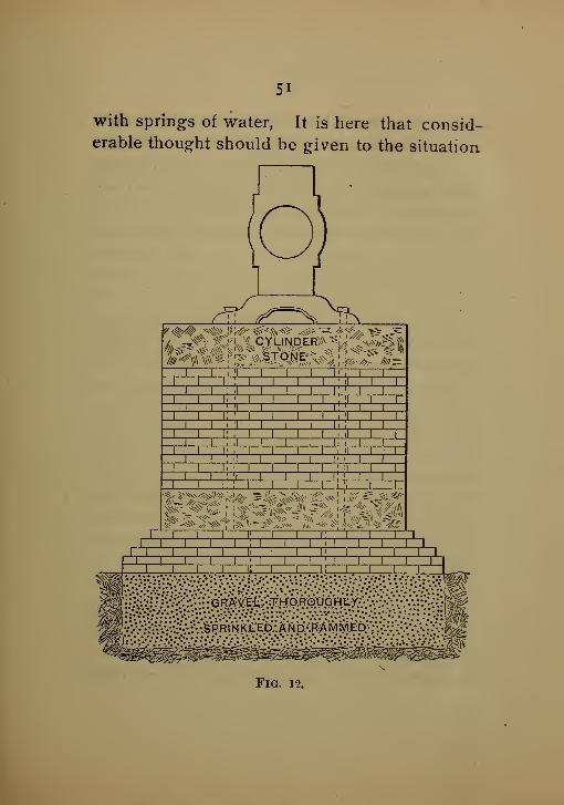
The width of base should be from 2 to 3 feet
more than the width and length of the engine
foundation proper, as shown by Fig. 12.
This foundation, or base, we may carry up
about 5 courses in height before we come to
the pocket-hole under the bottom stones, for
the nuts and washers of the foundation-bolts.
The absence of heavy footing stones, uponwhich to start our brickwork, may be looked
upon with some distrust by a few, but facts
have proven this arrangement to fully with-
stand the vibration, and to cover all of the re-
quirements for that purpose.
Hard-pan, or clay-bottom, may be treated in
the same manner. The most troublesome of
all material to deal with, and to sustain a
foundation upon, is quick-sand impregnated
5i
with springs of water, It is here that consid-erable thought should be given to the situation,
Fig. 12.

52
and means provided to safely accomplish, in an
economical manner, a first-class piece of work.
The most successful method of dealing with
this class of material, quick- sand, that has
come to our notice is that devised by Mr. Geo.
H. Corliss for the bottom of the foundation for
one of his pumping-engines, and its building
upon the bank of a river. This plan consisted
of driving down any amount of stone, or
other material, of small size, where required
by the lines of the building and space covered
by foundation of engine, by a weight in shape
of a ball weighing about 4,000 lbs. falling anyconvenient distance, varying from 10 to 25
feet. At each blow of the ball, rolling from a
cradle upon which it had been hoisted, the
loose stone, dumped from carts, were driven
into the sand, spreading out as they descended,
and finally making, as the work progressed byrepeated addition of material and subsequent
blows from the ball, a compact mass of
sufficient solidity able to stand the test of
years, without the least sign of settlement in
any part of the building, or foundation of
pump and engine.
This plan of such a novel and successful

53
character is susceptible of application to manylocalities where similar material is to be con-
tended with, and may be applied with the
assurance of affording an economical and,
at the same time, a successful means of
producing foundation for almost any construc-
tion.
CHAPTER XII.
Another plan is to excavate to the proper
depth required between and under sheet piling,
driven down as the excavation progresses un-
til the depth is reached, where a bed of con-
crete, formed by cement, sand, broken stone
or brick bats, is placed ; the depth of samevarying for each case to meet the requirements,
usually from 24" to 36", and of such a dimen-
sion of base as to present a large bearing sur-
face upon the sand. Upon this bed of con-
crete, after sufficient time has elapsed to allow
the material to harden and settle, is commencedthe brick work of the foundation.
If this plan is properly carried out, and care
taken not to cover too much space at a time,
so as to allow the mass to harden while the
process is in operation in putting down the

54
concrete bed, very good results may be ex-
pected for most constructions.
Crib-work, forming a heavy flooring madeof timber, is sometimes resorted to in founda-
tions, but as the bond between such material
and cement is not of the best, and what would
be desired for such work, we cannot consider
this plan as efficient as those already referred
to. Aside from the difficulty of getting an
even and solid bearing for a timber platform
upon the sand, any settlement of a part of this
yielding material is likely to cause trouble in
the foundation, from the lateral movementwhich may take place.
MATERIAL FOR FOUNDATIONS.
The most satisfactory materials, so far as
my judgment serves me, to build engine foun-
dations of, is a good quality of hard burned
brick, well laid in cement mortar, composed
of one part cement to one of sand, with plenty
of water used upon the brick, and while laying.
At the top, for the parts of the engine to rest
upon, granite blocks of good size or iron plates
may be bedded in cement, granite being by all
means the most desirable.
Similar blocks of granite should be provided

55
for the bottom and for the bearing surface of
the foundation bolts. This is far superior to
any wholly stone foundation that can be
built, for equal cost.
As a guide for the location of all bolt-holes,
throughout the work of building the founda-
tion, it is a very good plan to first prepare a
wooden templet, carefully laid out from the
drawings, and to cover all of the holes re-
quired in the foundation. This templet maybe made of one inch by six inch boards, as
shown by diagram, Fig. 13, securely fastened
together, and permanently suspended from the
roof overhead. From this templet may hang
at all times plumb-bobs over trie center of
each bolt-hole.
When the brick laying is commenced above
the bottom stone short, wooden boxes, three
inches square and about eighteen inches long,
may be used to build the brick around, to
form the bolt-holes, pulling the boxes up and
centering them anew as the work progresses.
Another plan to locate the position of bolt-
holes in a foundation is first to establish the
center line of shaft on the side walls of the
buildings, by securing targets made of J4

56
boards six inches wide, and upon this plainly
mark the position of shaft, relatively to walls
of building. Upon the end walls of building
Fig. 13.
fasten similar targets, one to represent the cen-
ter line of engine and one the center line of

57
back bearing. These two centers, of course,
being exactly at right angles to that represent-
ing center line of main shaft.
From this center line of engine, measure off
on the wall at each end of the building the dis-
tance each way from this center that is required
for the cylinder-foot bolts, and also, from this
same center line of engine measure off the off-
set for the main bearing. On the sides of the
building w7 e measure off an equal distance, each
way fro n the line established for the center of
the shaft, equal to that required for the holes in
the main and back bearings.
Also, from center of shaft we measure off
the distance required to the first cylinder-foot
bolt, and the distance between center of front
and back cylinder bolts.
From these different positions on target,
where, it is assumed, nails are driven, westretch stout lines, and at their intersection with
their corresponding line we hang plumb-bobs,
from wThich we may work, throughout the
whole height of foundation, for centering the
piece of joist, or box, which we use to form
the bolt-holes, a method already referred to.
5«
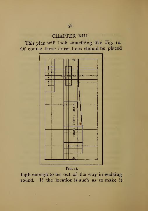
CHAPTER XIII.
This plan will look something like Fig. 14.
Of course these cross lines should be placed
5 r~
E-N-l RE -<>F- 5H*c
1
c
i
L
c
j
J
c
J
iz
1
r
J
, '
Fig. 14.
high enough to be out of the way in walking
round. If the location is such as to make it
59
inconvenient to carry out this plan, a substi-
tute for the walls of the building may be had
by building a fence, as it were, around the
space to be occupied by the foundation, and
upon which the various center lines may be
marked and lines stretched accordingly, from
side to side thereon. This plan is much moreconvenient, requiring less strength of line
(which is an advantage) than when long and
wide engine-rooms are to be met with.
In bedding the top as well as the bottom
stones down, in cement, it is a good plan to
first lower the stone to its place to establish its
level, and be centered each way, and after-
wards hoisted up about three inches, andblocks put under each corner at that height.
After mixing the quantity of cement required
of the proper consistency, the operation of
placing it under the stones, and leveling off
the whole surface, should be done as expedi-
tiously as possible, and the stone lowTered into
position. A heavy wooden mall or piece of
joist should be used endwise to bring it to a
bearing and approximate level.
In setting the top stones it is well to leave
them about A of an inch high, so as to allow

6o
"bushing" down to a proper level all around,
when the engine comes to be located.
Above all things, in building an engine foun-
dation, give no heed to the person who sug-
gests economizing in the material to be used in
it. It is very natural to suggest lime-mortar
in place of cement, but if done, we shall have
about as poor a foundation for the purpose as
could be conveniently built.
Aside from the extremely long time required
for mortar to dry out, it will not stand the
strain and jar to which it is subjected without
cracking after a time, as the sand is not nearly
so firm with lime as with cement-mortar. Thedifference in the benefit to be derived by the
use of the best quality of cement will not
allow, for a moment, a comparison between
the two materials. Instances may be cited
where engine foundations have been built in
this manner (with lime-mortar) that became a
source of annoyance and trouble when strain
was put upon the holding-down bolts, by the
mass giving way and settling; so that it wasdifficult to tell where the engine was, as to
line. Resort had to be made to shims placed
here and there, between the engine and stone,

6i
to make up for the deficiency caused by the
stone taking a different level when the engine
was screwed down.
This is the result of trying to save the differ-
ence between the cost of lime and cement, a
very small item where so much depends uponthe work for good running engines.
As we approach the top of foundation, pieces
of joist 4" by 6", should be built into the brick-
work at regular intervals, where most conve-
nient, to which we may fasten the floor-planks.
And at the side of foundation, spaces should be
left to receive the ends of the floor-beams, for
the engine-builder is the most proper person to
say where these floor-beams should be set so
as to be least in the way of the exhaust and
condenser pipes. These should be located
from the plan furnished with that object in
view, so as to readily admit making anew any
joint about the engine coming under the floor.
DRESSING DOWN TOP OF FOUNDATION.
After allowing sufficient time for the founda-
tion to season and dry out, we may commencethe operation of "bushing'' the tops of foun-
dation-stones to bring them to the proper level
at the places covered by the machinery. To

62
do this.properly we should provide ourselves
with a three-foot and a fourteen-foot straight-
edge, and a good spirit-level. After satisfying
ourselves as to the lowest place in the different
stones that is to be covered by the bearing
surface of our machine, we use that as a start-
ing-point, from which we are to determine the
proper level for the remaining portion of the sur-
faces of the different stones in top of foundation.
This is best done by providing short blocks,
say two inches square, upon which, at differ-
ent points, we rest the ends of our straight-
edge, one block being located at the starting-
point, while the other is set at that part of the
stone to be worked upon, dressing down with
the bushhammer until we reach the proper level.
After a number of spots at the proper level
have been established upon each stone, wemay work off the surplus between these places
to the best advantage, and finally, smooth
down the work to a bearing by a judicious use
of the bushhammer, using as a guide our short
straight-edge, having one edge rubbed with red
chalk, which being applied to the stone deter-
mines the high places that are to be removed

<>3
MANAGEMENT OF THE CORLISS ENGINE.
CHAPTER I.
The cotton manufacturing company, bywhom I have been employed for the past eight
years, is located on one of the New England
rivers, which furnishes very good water for
steam purposes. We have one large battery of
boilers in which the pressure is ioo pounds for
the simple condensing engines, and in line
with these there is a battery of six boilers, in
which the usual pressure is 125 pounds for the
compound engine.
All of these boilers are return tubular, with
overhanging fronts, and are 60 in. diameter,
with 76 tubes 3^ in. diameter and 21 feet long.
The distance from grate to shell of boiler is 24
in.
I am particular to give these dimensions for
the reason that I have found them very goodproportions, with the exception of distance
from grate to boiler, which should be some-
thing more, on account of the gaseous nature
ol the Cumberland coal that we use.
We have a small independent steam pump

64
connected to tanks, for weighing feed water,
and other instruments lor testing the evapora-
tive efficiency of the boilers, and trying differ-
ent kinds of fuel.
Numerous tests have proved that the 'best
method of burning bituminous coal is the one
mentioned in The Engineer of October 18, 1890,
p. 90, " The Smoke Nuisance" as the slow-firing
method. I allow but three shovels fall of coal
to each furnace door at a time, and alternate
from right to left hand door at each firing.
This does not prevent all smoke by any means,
but there is not an objectionable amount ap-
pearing at top of the chimneys at any time.
The method of coking the coal in front of
the fire, I have found very objectionable whentried in connection with an evaporative test.
The fireman cannot see the body of his fire and
there are sure to be thin places where cold air
rushes through ; and besides this it is very de-
structive to the front of the furnace.
Leaving the fire door open a little for a few
moments after each firing reduces the amountof smoke, but gives a lower result of water
evaporated on a week's trial. I have also
carefully tried introducing air through perfor-

65
ated plates in the bridge wall. This appeared
to promise success, judging by the appearance
of the fife as seen through sight-hoies on back
end of boiler, but I found by my testing ap-
paratus that this view of the fire was very mis-
leading.
The best results will be found with moderate-
ly thick fires, and while burning from 12 to 13
pounds of coal per square foot of grate per
hour.
I have met many engineers who seem to
think that slow combustion means more per-
fect combustion. I have found the reverse to
be true. A high firebox temperature, a clean
boiler, and low temperature of uptake, is what
is wanted.
All engineers who possibly can should have
apparatus for weighing feed water and makingevaporative tests, as the amount of steam used
for power and other purposes is liable to con-
siderable variation, and the weight of coal
alone does not always give a correct result.
Bv careful trials one can readily find out
what is best in any given case, and will un-
doubtedly find the unexpected sometimes, andthereby make a handsome saving in the coal

66
bills. These tests should not be less than one
week in duration.
I have found it best to leave the air passages
in furnace doors open at all times, while burn-
ing bituminous coal. The draught is muchbetter regulated by an automatic damper regu-
lator than by hand.
My experience with shaking grates has not
been very favorable. By a careful trial of one
week, of one of the best rocking grates in the
market, I failed to find any gain in economy of
coal ; in fact a slight reduction in pounds of
feed water evaporated. This was probably
owing to the reduced grate surface, as the
maker put dead plates three inches wide on
sides and back of furnace.
We have for a number of years used plain
grates in sections about 6 inches-wide and 21
inches long, air opening y2 inch, width of metal
bars y2 inch. I see no reason why they should
not last ten years.
In boiler rooms where there is shafting, the
Davis double plunger feed pump has proved to
be very reliable and durable ; 6 inch plungers
should not be run over 25 strokes per minute.
I would §ay avoid single plunger pumps, both

67
power and steam, on account of the pulsations
of the water in the pipes, and especially so if
you have a fuel economizer or large feed water
heater, as all the water contained in these
must come to rest at each change of stroke,
and must be made to move on again as the
plunger advances, while the duplex pumpkeeps the water steadily advancing all the
time.
. The feed pipe should not be less than twoinches in diameter, and is best when made of
brass, and introduced into the boiier on the
top at back end over the steam space. Where
the draught is sufficient the fuel economizers,
so-called, are true to name. The reduction in
fraught will amount to about 5-iooths of an
inch of water, and at this mill heats the feed
water from ho to 220 degrees.
All valves on water pipes should be of the
straight-way pattern. I use a gate- valve for
both steam and water, and provide all steam
valves over 3 inches with a ^ inch by-pass,
by which steam can be let into the pipe with-
out ^shock, which is very destructive some-
times.
The following is a copy of one of the many

68
tests that 1 have made : There was no special
preparation made for this trial, and no allow-
ance made for moisture in the coal. The coal
includes that used to get up steam from pold
water and banking fires :
.Duration of test. r ,2 day?-
Boiler pressure in pounds IDI
Temperature of feed in degrees 13°
Temperature escaping gases 392
Water evaporated in pounds 83,034
Coal consumed in pounds 8,397
Weight of combustible in pounds . • 7,891
Coal per square foot of grate per hour 131
Water evap. per pound coal, (actual conditions) 9,888
Water evap. per pound combustible 10,522
Water evap. per pound coal from and at 212. . . IM73
Water evap. per pound combustible from and
at2i2 .••••• • 11,889
Percentage of water in steam °-5
CHAPTER II.
In the last chapter nothing was said about
the quality of steam produced. This is a
point too frequently overlooked by engineers.
If you have upright boilers which moderately
superheat the steam, you are all right in this
respect, but with horizontal tubulars there is a
strong probability of there being too much

69
moisture in the steam. This can be determined
by the calorimeter test, which has been fully
explained in engineering papers. I do not
consider that high evaporative results from
horizontal boilers are of any value, unless ac-
companied with the calorimeter test, showing
that the steam produced is quite dry.
This tendency of horizontal boilers to fur-
nish wet steam is the reason why I prefer well
designed uprights when high steam is required
for compound engines. One gauge of water
while engines are running, and continuous
feed, will prevent an excess ot water passing
away with the steam in boilers of good design.
1 depend entirely on gauge cocks, having no
glass gauges whatever. These boilers in mycharge are over 10 years old, and, all told,
there are over 22 hundred tubes ; not one of
them has ever leaked from any cause.
We are all aware that properly covered pipes
contribute largely to the economic results. I
have found that hair felt, with asbestos mill
board next to the pipe, makes a good cover-
ing, but for a short time only. The asbestos
does not prevent the felt from burning on top
of pipe ; in 6 months it will be found nearly,

70
if not quite, destroyed, and on the bottom it
will be hanging loose from the pipe. Onflanged pipe I use one inch each of Nos. i and
2 asbestos cement, and outside of this, one
inch of hair felt. This brings the covering out
even with the flanges ; then all is covered
with heavy cotton cloth, and for the boiler
room it is whitewashed; in the engine roomsit is covered with a jacket of Russia iron, and
brass bands to break joints.
In regard to the size of steam pipe to the
engine, I would say : Do not be governed bythe capacity of opening into the cylinder or
the valve furnished by the builders. The high
piston speeds now so common require larger
pipes, and if they are long, considerably larger
diameter should be used. The Corliss cross
compound engine, of which I am about to
write, has cylinders 22" + 40" by 60" stroke,
and runs 60 revolutions per minute. Thethrottle is 7" and the steam pipe about 200 feet
long. I enlarged from the throttle with a short
piece of cast-iron pipe up to 10", and the bal-
ance is made of 10" boiler tubing in long
lengths, with heavy cast-iron flanges riveted
on. All bends are made of copper. Such a

7*
steam pipe as this is far more reliable lor high
pressures than cast-iron or common wrought
pipe with screwed joints.
The cylinders ot this engine are proportioned
in this way on account of the unusual amountof steam required for use in the mills, which is
taken from the receiver. Besides seven slash-
ers (which turn off something over ninety
thousand pounds of yarn each week), there
are eighty vapor-pots in the weaving rooms,
all of which are supplied from this source.
The usual pressure in receiver is five pounds.
This engine has been running two years, and
is connected to ten water-wheels of 180 h. p.
each. There are no regulators on the water-
wheels, the engine governor controlling the
speed of all. From this and other causes, the
load is quite variable, and with full river the
engine is sometimes underloaded.
As left by the builders, I at first had trouble
to maintain an even pressure in the receiver,
and furnish steam for use in the mills, as the
point of release on both cylinders was deterr
mined by the governor, and no way was pro-
vided to change the cut-off on l.p. cylinder.
This would be correct under certain conditions,
72
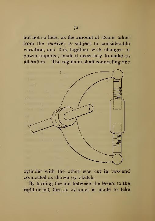
but not so here, as the amount of steam taken
from the receiver is subject to considerable
variation, and this, together with changes in
power required, made it necessary to make an
alteration. The regulator shaft connecting one
cylinder with the other was cut in two and
connected as shown by sketch.
By turning the nut between the levers to the
right or left, the l.p. cylinder is made to take

73
more or less steam, as the case may be, and
at the same time it is controlled by the regu-
lator.
During a large part of the time the l.p. cyl-
inder is made to cut off somewhat earlier than
would be the case if a low steam consumption
by this engine alone was desirable. It is the
total coal used that interests the stockholders.
During the season of low river, when other en-
gines are furnishing the steam for use in the
mills, and this engine is running under favor-
able conditions, the coal consumed during a
test of one week, including that used for bank-
ing fires at night, was 1.73 lbs. per h.p. per
hour.
The exhaust steam from the duplex feed
pump on this trial was used to heat the feed
water for another set of boilers than those from
which the engine steam was taken. As run-
ning at present—with an overflowing river,
and steam taken from the receiver for the
mills, as mentioned above—the coal used per
h.p. per hour varies from 1.9 to 2. 1 lbs.
The variations in load, sometimes caused
the receiver pressure to fall quite low, un-
noticed by the engineer. This made bad work

74
and loss in the slasher room. To prevent this
loss, and give us timely notice, I connected a
small whistle to pipe leading- to slashers, as
shown by sketch.
A pressure of 5 pounds nolds the valve downto its seat, but at 4^ pounds the weight lifts
the valve, and blows the whistle before there
is any cause for complaint in the mill, and the
oz:
engineer has time to make the proper adjust-
ment of the cut-off on the l.p. cylinder, or
open the by-pass valve into receiver.
The air pump is the regular Corliss pattern,
34 in. by 12 in. stroke. A part of the over-
flow, with the water of condensation from
the receiver, is returned to boiler room. A
75
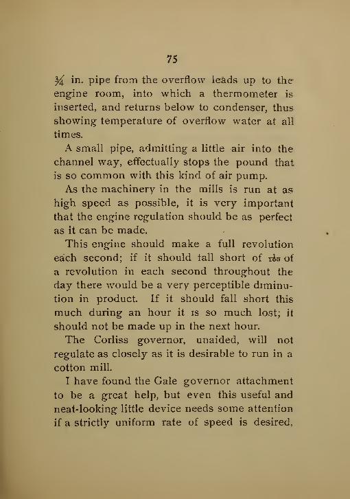
Y^ in. pipe from the overflow leads up to the
engine room, into which a thermometer is
inserted, and returns below to condenser, thus
showing temperature of overflow water at all
times.
A small pipe, admitting a little air into the
channel way, effectually stops the pound that
is so common with this kind of air pump.
As the machinery in the mills is run at as
high speed as possible, it is very important
that the engine regulation should be as perfect
as it can be made.
This engine should make a full revolution
each second; if it should tall short of x&n of
a revolution in each second throughout the
day there would be a very perceptible diminu-
tion in product. If it should fall short this
much during an hour it is so much lost; it
should not be made up in the next hour.
The Corliss governor, unaided, will not
regulate as closely as it is desirable to run in a
cotton mill.
I have found the Gale governor attachment
to be a great help, but even this useful and
neat-looking little device needs some attention
if a strictly uniform rate of speed is desired,
76;
I suppose the Moscrop recorder is an excellent
thing to show the variations in the speed. Agood many years ago, before I ever heard of a
"Moscrop," or other device for this purpose, I
made a little machine, which is still doing
splendid service. On the shaft of the air pumprocker is fixed a small adjustable arm carryii ga ratchet, which picks one tooth at each rev-
olution of the engine in a ratchet wheel of an
equal number of teeth, with revolutions de-
sired by the engine in one minute. On the
shaft of this ratchet wheel there is a pair of
mitre gears, by which this movement is taken
up into the engine room, where, at a con-
venient place, there is a clock dial with suitable
train of gears to run a minute and "second
hand."
After the engine is started, the hands on
this dial are set to exactly agree with the
engineer's time. After an hour's run, if there
is a gain or loss of one second, which meanswith this engine one revolution, it is easily de-
tected and corrected. This dial makes norecord of the revolutions for yesterday or last
week, but as it enables us to run just right all
the time; it is very satisfactory. The engine

11
register or counter shows each day the num-
ber of revolutions, and this is recorded for each
engine, with all other matter of interest, in a
logbook kept for this purpose.
These cards were taken November 4. There
was not sufficient load for the engine to show

78
its best work. The cards from the other ends
are as nearly the same as can be. Springs in
indicators, 60 and 12 to the inch.
CHAPTER III.
The compound from which the indicator
cards in the last chapter were taken is said to
be Mr. Corliss's final and perfected engine. It
certainly is very economical in the use of
steam, and many parts are excellent in design,
but there are others which are not quite per-
fect.
There is no means provided to raise the
pistons as they wear below the center; the
steam packing rings are let into the head,
there being no bull-ring. The piston can be
turned around on the rod, which will make up
for the wear on the packing rings, but not for
the wear of the cylinders. The slides are very
much too narrow ; there is not sufficient bear-
ing surface for heavy loads. The pillow blocks
are all that could be desired, 24 in. length of
bearing for an 11 in. shaft. The hand hole in
the side, which enables the engineer to dis-
cover any heating before it has pervaded the
whole mass, is a very good thing. The shaft
79
is 15 in. in diameter in the center, and carries
a 25 ft. wheel, weighing fifty thousand pounds.
The valve gear is very peculiar, and different
from any other Corliss engines made. Thewrist plates are nearly as large as the sides of
the cylinders, and the valve connections are,
consequently, very short ; this gives the valve
a very quick movement. The vacuum dash-
pots close the valves very quickly, as will be
seen by the cards. The piston rods have U. S.
metallic packings, and the valve rods are
packed with Garlock's patent sectional rings.
This engine has run two years, and has been
stopped but once during working hours from
causes arising in engine room. One of the ad-
justing screws on the cross head gibs worked
loose soon after the engine was left by the
builders, and it was necessary to stop. I have
put preventers on all of these screws, as I
found that they had a tendencv to work loose.
I saw an item in the daily papers of an en-
gine of this type running away and breaking
up badlv ; the question has been asked, whythe governor did not take care of it ? I should
say that the cut-off rods were so set that whenthe governor balls were at their extreme height,

8o
the low-pressure cylinder would still take somesteam as long as there was any in the receiver,
and there would be enough (with the Vacuum)to do mischief.
There are some features about another en-
gine, in my care, which may possibly be of
interest to engineers, who may have similar
conditions.
This is a double high-pressure condensing
engine, having cylinders 26 in. by 60 in. stroke,
running 58 revolutions per minute; built at the
Corliss Steam Engine Co.'s Works, in 188 1. It
can be run ^, y2 , $£, or all condensing.
During a few weeks of very low river in the
summer we run all condensing, in order to get
full power, some times as much as 950 h.p. I
have never been able to test the steam con-
sumption with this load, but it is not of these
conditions that I am about to write.
This engine runs in connection with six
waterwheels of 180 h.p. each. Several years
ago, during the season of high water, this en-
gine was disconnected from the mill, the
waterwheels doing all the work, the steam for
the slashers and vapor for weaving rooms be
ing furnished direct from the boilers. As there

8i
was not sufficient power in the wheels to
insure good regulation, there was a diminished
product in the mill. The slashers and vapor-
pots were then piped for exhaust steam, and
one cylinder only of the engine was run non-
condensing, with five pounds back pressure.
Sufficient water was taken from the water-
wheels, to give the engine a load of ioo to 150
h.p. The result was very satisfactory, perfect
regulation and full product in the mill, and less
coal consumed than was required to do the
mill work with direct steam. The gates on the
wheels were so regulated that there was very
little, if any, steam escaped through the back
pressure valve.
For the past two years, owing to the en-
largement of the mill, the load for one cylinder
was such that there was about twice as muchexhaust steam as the mill required. Besides
this loss of steam, there were many days dur-
ing the last part of the afternoon, when the
river was somewhat low, that the load was far
too much for one cylinder, while in the morn-
ing one cylinder was ample. I then com-
pounded this engine as shown by sketch.
A piece of 2.0 in. pipe was placed in the ex-

82
haust from the high-pressure cylinder, which
answers for a receiver ; from this we piped to
the two-way valve on top of low-pressure
cylinder. The throttle that was taken from
this cylinder was placed in this new pipe.
For more than two years this engine has run
fc. /
^«/rA\> ))sVM/ CO
1_
o oH 03
o
dnu jf-yin
with this arrangement, giving perfect satisfac-
tion.
Besides running very economically with light
load, one important advantage is that I always
have the low-pressure cylinder connected, and
ready for heavy loads, and the change is made

83
from compound to simple condensing, while
running, and without any perceptible changein the speed.
The amount of power derived from the low-
pressure cylinder is quite small, from 60 to 90
h.p., but this is obtained from steam that would
otherwise be thrown away, and the 5 pounds
back pressure must be maintained. When run-
ning compound, with load of400 h.p. or under,

84
and steam taken from the receiver for four
slashers and twenty vapor-pots, the coal re-
quired is 2.25 pounds per h.p. per hour. With
one cylinder non-condensing, and furnishing
the same amount of steam for use in the mill,
and the other cylinder condensing, the coal re-
quired is 2.69 lbs. per h.p. per hour. The cards
shown were taken November 8, with light load.
The springs used were 40 and 12 to the inch.
I am aware that these are not perfect cards,
but I think it will be generally admitted that
the result, taken as a whole, is very good.
As to setting Corliss' valves, I can add noth-
ing to the full and correct article published in
The Engineer, by John T. Henthorn, mechanical
engineer, of Providence.
When starting, as soon as the engine has
made two or three revolutions, I raise the gov-
ernor a little, by a thumb nut, in order to makethe cut-off operate. This diminishes the liabil-
ity to take water from the boilers and greatly
aids the engineer in getting a vacuum.
The noise from the dashpots was somewhatharsh, and this was remedied by bolting a small
box-shaped casting over the outlet holes, and
from this running a i}( in. pipe, with cock in
§5
it below the floor. All the principal parts of
the engines in my care are oiled by stationary
sight feed cups. The cylinder oil is introduced
at each end of the cylinders. The oil for other
parts I usually mix 3 parts paraffine to one of
sperm, and one of neatsfoot. This mixture
costs 32 cents per gallon, and will run the
heaviest shaft and not gum.
Usually a very small quantity of oil is suffi-
cient for crank-pins and cross-head wrists, but
my experience has taught me that main bear-
ings should have a very generous quantity reg-
ularly applied, carefully collected in drip pans,
and strained and used again. With an expe-
rience of over thirty years, I have never
stopped an engine for a hot pillow-block. Thecost of all the oil for the 26 in. double engine
mentioned, including two jack shafts, is twenty-
seven cents per day. The compound engine
requires about the same quantity. A pair of
23m. x 6oin. engines, running 66 revolutions
per minute, are oiled for seventeen cents per
day.
Some experience with the indicator, together
with my observation of the running of manynon-condensing Corliss engines, leads me to

86
the opinion that far .more than one-half of
these engines are running under-loaded. Tospeak more correctly, I would say that the ma-jority of engineers carry a higher pressure of
steam than their work calls for.
This may be equally true of other automatic
engines, but I have found it so frequently the
case in Corliss engine rooms, and so difficult
Scale 50
to convince engineers of their error, that I
mention it here. The first card taken is gen-
erally like the one I have constructed for the
purpose of illustration. It will be seen that
the fly-wheel is driving the piston during one-
half of the time. The pressure of the steam on
the piston is like a series of kicks, but it is not

87
best to let it kick so hard that it will kick back.
The strain on the crank pin is greater, and the
valves work harder while running in this
way.
CHAPTER IV.
Another very important reason why the en-
gines should not be operated in this manner,
is the greatly increased cylinder condensation,
owing to too great range of temperatures.
The difference between the temperature of
the initial pressure of this diagram and the ab-
solute terminal pressure is about 140 degrees;
whereas if the steam had been lower, say 60
pounds total, and the terminal about the sameas the back pressure, the difference in the tem-
peratures would have been only 80 degrees.
It will be seen that there is a difference of 60
degrees in favor of running with the lower
steam pressure ; nearly as much as there-
is between a winter and a summer day.
I do not wish to be understood as advocat-
ing low pressures, but would say—do not al-
low a loop in the card while the engine is do-
ing regular work. This may appear to manyas an extreme case, but I have frequently

88
found the loop in the card from engines which
were represented by engineers as heavily
loaded.
There are a great many old Corliss engines
that have the packing rings set out by set
screwTs against elliptic springs. I would ad-
vise engineers who can't get anything better
than this, to be extremely careful when setting
out these screws. The best way is to stop the
engine on the front centre, disconnect the main
rod, and pull the piston to the back end ; then
it can be ascertained by moving the piston
back and forth when it is just right. It should
be so easy that one man can readily move a 20
inch piston in the cylinder.
The Corliss engines of later make have a
single packing ring, in small sections, let into
a junk ring. This is a great improvement
over the other, as it requires no setting out,
and runs very satisfactorily ; but judgment
should be used in setting up the screws for the
purpose of centering the piston head. These
are frequently set up so hard as to strain the
junk ring out of round. If the junk ring nearly
fills the bore of the cylinder (as it should), this
strain causes it to bear very hard in these four

89
places, causing undue friction, and sometimes
injury.
The follower of this kind of piston is usually
secured by large steel bolts. I have no doubt
that many engineers have had serious trouble
in starting these bolts. I remedy this by coat-
ing the bolts with a mixture of Dixon's graphite
and cylinder oil. This mixture is just the
thing for pipe and other bolts about boilers,
which are sure to stick unless something of
this kind is used.
We are frequently told by the newspapers
that a very large proportion of the accidents
in engine and boiler rooms are the result of
carelessness, and right here they stop and
leave the general reader with the impres-
sion that it is the engineer in charge whois responsible. Carelessness and ignorance
on the part of builders, and indifference
on the part of owners, cause the greater part
of the accidents. The engineer is gener-
ally expected to get along with what he has,
and very frequently cannot clean his boilers
for lack of opportunity. I find in a copy of
The Locomotive the monthly report of the inspect-
ors of the Hartford Steam Boiler Insurance Co.
,

9°
the following items :
'
' Cases of defective rivet-
ing, 1,658 ; cases of deficiency of water, 6."
Engineers and their assistants were faithfully
attending to their boilers that month, and all
the reports show about the some proportion.
It is very much the same in the engine room,
but we have no insurance company to publish
records of defects that may exist there. If wehad, there would be a large number of Corliss
engines which would have to be stopped and
have larger piston rods put in. There are a
great many of these engines running that were
built some twenty-five years ago (designed for
a mean pressure of 30 pounds and a piston
speed of about 350 feet,) that have been speed-
ed up and the pressure increased. ^When one
of these engines breaks down they usually
send to the shop ; the wise man com.es and
tells the manager that there was too muchwater in the boiler, and that the engine wasblown up by too much water ; now the boiler
is blown up by too little water, while it is very
rarely the case that there is a grain of truth in
either statement.
Boilers thai are not strong enough to with-
stand the pressure explode, and overloaded en-
9*
gines of faulty design and poor material are
liable to accident, while a really first-class
man is doing all in his power to prevent it
The older engineers of the country will re-
member when the original builders of the Cor-
liss engine used cast-iron main shafts, and the
numerous breaks caused by them ; and still wehave cast iron cranks, cross-heads and valve
arms. The spring of the cast-iron crank on a
full loaded engine is quite appalling. Put the
engine on the center, and work the valves byhand, and measure this deflection. Certainly,
a stiffer crank is needed.
The valve arms seldom break if the valves
are properly oiled. Oiling the cylinder three
or four strokes with the oil pump every ten or
fifteen minutes will require nearly one gallon
of oil per day, and still the valves will be dry
nearly half the time. The Corliss oil-pump
discharges one cubic inch at each stroke, and
that single stroke does not oil the cylinder and
valves any better than one drop ; therefore it is
much better to have good automatic sight-feed
cups for this purpose.
The cast-iron cross-heads are seldom sound,
and the manner in which they are suppoited is

92
very faulty. The latest patterns correct this,
but there are a great many of the old style in
use that can be improved by the engineer in
the manner shown by the illustration.
The nut under the cross head in Fig. i will
not hold the cross head firmly, and long con-
^> «y
T£j 4^
rjui m m rtrti^ ,tn
Fig. I Fig. 2
tinued working will be likely to break the pis-
ton rod. This movement of the cross head at
the outer end cannot be seen, but it is there all
the same. The support given by the bolts
from the V, as shown in Fig. 2, are adjustable,
and remedy this trouble.


P^Ml
