the condensation of vapours of binary immiscible...
TRANSCRIPT
The Condensation of Vapours of Binary
Immiscible Liquids
by
ALAN WALTER DEAKIN
A thesis presented for the degree of Doctor of Philosophy
in the Faculty of Science and Engineering
Department of Chemical Engineering
University of Birmingham
September 1976.

University of Birmingham Research Archive
e-theses repository This unpublished thesis/dissertation is copyright of the author and/or third parties. The intellectual property rights of the author or third parties in respect of this work are as defined by The Copyright Designs and Patents Act 1988 or as modified by any successor legislation. Any use made of information contained in this thesis/dissertation must be in accordance with that legislation and must be properly acknowledged. Further distribution or reproduction in any format is prohibited without the permission of the copyright holder.

ro
SUMMARY
Heat transfer data are reported for the condensation of steam-toluene
and steara-trichloroethylene eutectic mixtures on 25.4 mm diameter oxidised
copper and gold plated horizontal tubes. Data are also presented for
the condensation of pure steam, toluene and trichloroethylene on the
oxidised copper tube and the film heat transfer coefficients obtained
agree to within + 20% of the Labunstov form of the Nusselt equation*
For the binary immiscible systems the heat transfer coefficients
decrease as the temperature difference increases, with the oxidised copper
surface giving higher coefficients than the gold. These differences are
attributed to the two observed fundamental mechanisms of condensation, a
channelling mode on the oxidised copper and a standing drop mode on the
gold. Models based on the different mechanisms are proposed and predict
the experimental results to within j^ 20%.
Finally it is postulated that the temperature dependent mutual
solubilities affords an explanation of the formation of the large
number of very small droplets observed during the condensation of these
eutectic mixtures.
Acknowl edq ement s
The author wishes to express his thanks to his joint supervisors,
Dr. Adrian Boyes and Mr. David Butterworth for their constant advice and
encouragenvjri't during trie courso of chii3 study.
Jack Pullingand Archie Morley are thanked for their help in the design
and construction of the apparatus and M.J.C. Moore, 1 and R.G. Given for
their many helpful discussions during my stay at Harwell.
Thanks are also due to the staff of the Thermodynamics Division
Harwell who all, at one time or another, helped in some way to the completion
of this work.
Finally thanks are due to the United Kingdom Atomic Energy Authority
for their financial support of the author.
ontents
.
Chapter 1. Introduction
Chapter 2. Literature Survey
2.1 Introduction 32.2 Laminar film condensation 32.3 Dropwise condensation 82.4 Condensation of vapours of immiscible liquids 8
2.4.1 Experimental studies on binary systems H2.4.1.1 Investigations using -horizontal H
tubes2.4.1.2 Investigations using vertical 17
surfaces2.4.2 Multicomponent systems 212.4.3 Models and correlations 21
2.4.3.1 Homogeneous models 222.4.3.2 Shared surface models 232.4.3.3 Other models and correlations 24
2.5 Conclusions 3 0
Chapter 3. Apparatus and Procedure 32
3.1 Introduction 323.2 Apparatus 32
3.2.1 Vapouriser circuit 353.2.2 Test section 353.2.3 Concensate circuit 373.2.4 Cooling water circuit 373 "~) tr /—,-- — ^v-^cpvr —i -"-*,=» 38
• C..~/ *— / . ix_- —— __^3 ST i *- — • —— ' *—
3.2.6 Thermocouple calibration 403.2.7 Total condenser 403.2.3 Liquids used 4 *Procedure 4
Chapter 4. Results 42
4.1 Introduction 4 24.2 Pure component data 424.3 Immiscible liquid data 42
4.3.1 Heat transfer data 424.3.2 Observed flow patterns 42
Chapter 5. Theory 53
5.1 Introduction 535.2 Channelling model 535.3 Standing drop model 55
Chapter 6. Discussion and Conclusions 60
6.1 Introduction 606.2 Pure component data 606.3 Immiscible liquid data 65
6.3.1 Effect of film temperature difference 656.3.2 Effect of tube surface 656.3.3 Discussion of the heat transfer data 72

Page
6.4 Comparison betv;e~n theory and data 776.5 Nucleation barriers 866.6 Conclusions and P.ecornmendations 88
References 90
Nomenclature 95
Appendices
Appendix A Physical properties 100 Appendix B Tabulated results 107 Appendix C Determination of n for use in the standing drop 115
model Appendix D Nucleation barriers in immiscible liquid conden- 117
sation Appendix E The effect of variable wall temperature on the 122
laminar film condensation of a pure vapourAppendix F Experiments on a vertical copper surface 129 Appendix G Error analysis 137
List of Figures
Figure
2.1 Temperature composition diagram for a totally 12immiscible binary system
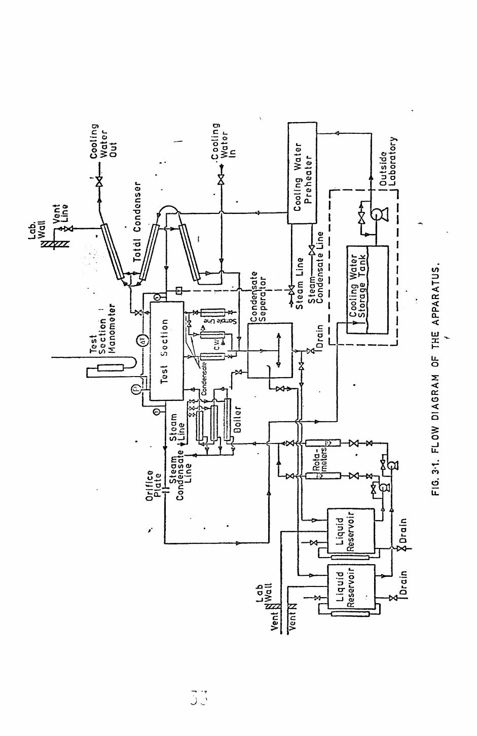
3.1 Flow diagram of the apparatus 33
3.la Overall view of the apparatus 34
3.2 Diagram of the test section 36
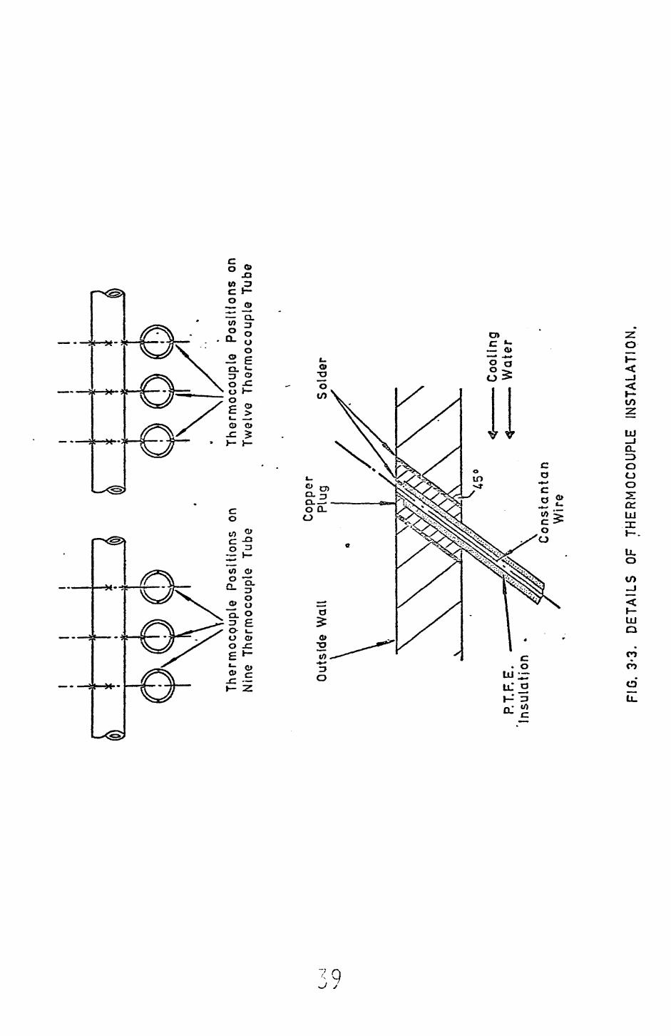
3.3 Details of thermocouple installation 39
4.1 Film heat transfer coefficients for the 44condensation of pure steam on an oxidised copper tube.
4.2 Film heat transfer coefficients for the conden- 45sation of pure toluene on an oxidised copper tube.
4.3 Film heat transfer coefficients for the con- 46densation of pure trichloroethylene on an oxidised copper tube.
4.4 Film heat transfer coefficients for the con- 47densation of steam-toluene rJLxtures on an oxidised copper tube.
4.5 FiL~ heat transfer coefficients for the 48condensation of steam-toluene mixtures on a gold plated copper tube.
4.6 Film heat transfer coefficients for the 49condensation of stearn-trichloroethylene mixtures on an oxidised copper tube.
4.7 Film heat transfer coefficients for the 50condensation of steam-trichloroethylene mixtures on a gold plated copper tube.
4.8 Flow pattern for the condensation of steam- 51toluene mixtures on an oxidised coppertube.
4.9 Flow pattern for the condensation of steam- 51trichloroethylene mixtures on an oxidised copper tube. /
4.10 Flow pctttern for the condensation of steam- 52toluene mixtures on .a gold plated tube.
4.11 Flow pattern for the condensation of steam- 52trichloroethylene mixtures on a gold plated tube.
Paqe
6.1 Film heac transfer coefficients for the 62condensation of pure steam on an oxidised copper tube.
6.2 Film heat transfer coefficients for the 63condensation of pure toluene on an oxidised copper tube.
6.3 Film heat transfer coefficients for the 54condensation of pure trichloroethylene on an oxidised copper tube.
6.4 Comparison of the trends in the data for the 55immiscible systems used in this study.
6.5 Solubility data for water-toluene mixtures. 69
6.6 Solubility data for water trichloroethylene 70mixtures.
6.7 Comparison of the steam-toluene data from this 73study.
6.8 Comparison of the steam-trichloroethylene data 74from this study.
6.9 Comparison of existing steam-toluene data 75in the composition range 78-85% by weight toluene in the condensate.
6.10 Comparison of existing steam-trichloroethylene 73data in the composition range 92—95% by weight trichloroethylene in the conden sate.
6.11 Comparison between the channelling model and 79the data for the condensation of steam toluene mixtures on an oxidised copper tube.
6.12 Comparison between the channelling model and 80the data for the condensation of steam- trichloroethylene mixtures on an oxidised copper tube.
6.13 Comparison of Bernhardts equation against 82experimental data for steam toluene mixtures.
6.14 Comparison between the standing drop model 84and the steam-toluene data obtained on the gold plated tube.
6.15 Comparison between the standing drop model 85and the steam-trichloroethylene data obtained on the gold plated tube.

Dl The nucleation of a water crop on an organicfilm.
D2 Plot of contact angle vs. degree of subcoolingfor the condensation of a si earn— toluene eutectic mixture.
El Co ordinate system for the no", isothermal wall 123analysis.
E2 Plot of h/h>T vs. 0 127Nu
E3 Plot of h/h^ vs ca
Fl Block diagram of the flat plate rig. 13 °
F2 Details of the test section.
F3, Film heat transfer coefficients for thecondensation of steam-toluene mixtures on a vertical copper block.
F4 Flow pattern for the oondensation of s team-to mixtures on a vertical flat plate

List of Tables
Table
1 Summary of various investigations 9
Al Physical property correlations for water 101
A2 Physical property correlations for toluene 103
A3 Physical property correlations for tri- 105chloroethylene
Bl Data for the condensation of pure steam 108
B2 Data for the condensation of pure toluene 109
B3 Data for the condensation of pure trichloroeth- 110ylene
B4 Data for the condensation of steam- 111toluene mixtures on an oxidised copper tube
B5 Data for the condensation of steam- 112toluene mixtures on a horizontal gold plated copper tube
B6 Data for the condensation of steam-trichloro- 113ethylene mixtures on a horizontal oxidised copper tube
B7 Data for the condensation of steam—trichloro- 114ethylene mixtures on a horizontal gold plated copper tube

Chapter 1
Introduction
The condensation of vapours has been extensively studied, both theoret
ically and experimentally during the past sev-nty years. A great number
of these studies have been concerned with the condensation of pure
vapeurs and in particular steam.
By comparison work on vapour mixtures, particularly those mixtures
which form immiscible liquids on condensation, has been uncommon. The
probable reason being that steam condensation in particular is a much
more important industrial process than that of vapour mixture condensation.
However, the condensation of vapours which fcrm immiscible liquid condensates
is nevertheless common in industrial practice. For example steam dist
illation and azeotropic distillation processes commonly give vapours
which form immiscible licuid mixtures on condensation, as do certain
chemical reactor processes, particularly those associated with the petroleum
industry.
To cesign condensers for the above processes it is necessary to
know the values of the condensing heat transfer coefficients. Most of
the previous studies on "immiscible liquid condensation" were primarily
concerned with the determination and prediction of these heat transfer
coefficients.
It is apparent from the earlier investigations that the condensation
processes involved are extremely complex. And although several studies
have been made the effects of certain important parameters are still
n»t clear.
The principal objectives of the present study were to investigate
several of these potentially important parame-ers. In particular the effects
on heat transfer performance of film temperature difference,condenser
tube surface properties and condensate flow regimes were studied.
2

Chapter 2
Literature Survey
2.1 Introduction
Pure single component vapours have been found to condense on a cooled
surface in one of two ways. The condensate may forn either a continuous film
or droplets; these two modes of condensation are termed filmwise and dropwise
respectively.
When condensing vapour mixtures, the modesof condensation •'
vary.. For miscible liquids the condensate
usually forms a film, although Mirkovitch and Missen (1961) have reported
systems which form both films and drops. In the case of immiscible liquids the
condensate consists of both films and drops of different liquid phases. Thus
the mechanism of condensation of vapour mixtures, particularly of immiscible
liquids, is much more complex than for pure vapours.
Most of this chapter is devoted to a detailed review of the literature on
the condensation of vapours of immiscible liquids. However, a brief survey of
filmwise and dropwise condensation is given first. No review is given for the
case of vapours of miscible liquids but the interested reader is referred to
van Es and Heertjes (1962) for details.
2.2 Laminar film condensation
Musselt (1916) derived theoretical equations for predicting the heat
transfer coefficients obtained during the filmwise condensation of a pure
vapour. The eouations are
X q °' 25
p AT B
where: C = 0.728 and B = D for horizontal tubes ando
C = 0.943 and B = L for vertical tubes

^ = T - T f s w
T is the saturation temperature^^
T is the wall temperature.
The other symbols are defined in the nomenclature,
An alternative form of equation (2.1) is
hN /—tr-r . P I *=•) (2.2)
where: P = 1.47 or 1.51 for horizontal and vertical tubes respectively
T is the mass flowrate of condensate per unit width of film.
The main assumptions used to derive the above equations were as follows:
1) The only significant resistance to the condensation process is presen
ted by the liquid film.
2) The condensate flow is laminar.
3) The wall temperature is constant.
4) The fluid properties are constant.
5) Subcooling of the condensate nay be neglected.
6) There is no vapour drag on the condensate film.
7) Acceleration of the liquid film is negligible.
8) The temperature gradient through the film is linear.
Many of the later workers have relaxed the restrictions
imposed by the above assumptions. Bromley (1952) and Rohsenow (1956) took
account of the subcooling and non linear temperature gradient effects, the
final equation being
hR/hN = (1 + 0.68 e)°* 25 (2.3)
where e = C AT A. P f

The above equation is widely used in place of the original Nusselt equation.
Sparrow and Gregg (1959) give a boundary layer treatment of laminar film
condensation in which the liquid film acceleration as well as the convective
terms were included. Chen (1961), using the integral form of the boundary
layer equations, ar.d Koh, Sparrow and H-irtnett (1951) using the differential
boundary layer equations, took account of the effects of drag due to the
initially stationary vapour, as well as the terms included by Sparrow and
Gregg. The inclusion of vapour drag terms made a significant difference for
low Prandtl number liquids (e.g. liquid metals) but was not significant for
liquids with Prandtl numbers greater than one. The agreement between the
solutions of the integral and differential forms of the boundary layer
equations is excellent.
Chen presents approximate equations for predicting the heat transfer
coefficients for a vertical plate and a horizontal tube which are within 1% of
the detailed numerical solutions. The equations are, for a flat plate
h /hM = c N
1 + 0.68 £ + 0.02 (e /Pr)
1 -f 0.85 (s/Pr) - 0.15 (e2/Pr)
0.25
(2.4)
and for a horizontal tube
hc/hN=1 -f 0.68 e + 0.02 /Pr)
1 + 0.95 (e/Pr) - 0.15 (£/Pr)
0.25
(2.5)
where e = C AT /x and Pr = C u/k. p f p^
The above equations are valid for liquids with Prandtl numbers larger
than 1.0 and for those v/ith Prandtl numbers less than 0.05 provided e ^ 2.0,
Comparing equations (2.3), (2.4) and (2.5), it can be seen that they
agree if the Prandtl number is large; in fact if Pr > 1.0 and e <*' 0.2 there is
no significant difference between the Chen, Rohsenow and Nusselt equations.

Most common liquids have Prandtl numbers between 1.0 and 10.0, It is
therefore apparent that the detailed boundary layer treatments show that
Nusselts equation is adequate for such liquids. Large deviations are only
expected for low Prandtl number fluids (e.g. liquid metals) and for high
condeasate subcoolirgs (e > 0.2).
All of the above treatments assume the physical properties of the
condensate film are constant. Drew has shown (see McAdams (1954)) that if the
temperature distribution is linear and it is assumed that the viscosity varies
inversely with temperature, then the effects of variable viscosity can be
estimated by using Nusselts equation with the viscosity evaluated at a
reference temperature given by
T „ = T + 0.25 AT. (2.6)rer W f
Voskresenskiy (1948) and later Labuntsov (1937) incorporated a linear varia
tion in the condensate thermal conductivity as well as the above viscosity
variation. Labuntsov showed that if the physical properties in Nusselts
equation are evaluated at the vapour saturation temperature a simple correction
can be applied to take account of the conductivity and viscosity variations
across tha film. Thus
h . h. 4 C2.7)
and 9 7 = f (k 3 n )/(k 3/U >] * (2.8)j-> W o o W
where: o_ is the Labuntsov correction factor, k and n are the thermal r L w pw
conductivity and viscosity of the condensate evaluated at the wall temperature.•
k and u. are the thermal conductivity and viscosity of the condensate s s
evaluated at the vapour saturation temperature. Foots and Miles (1967) have
shown that for the condensation of pure steam the above methods of taking
account of variable fluid properties are adequate even at very large tempera
ture differences (i.e. AT = 100°C).
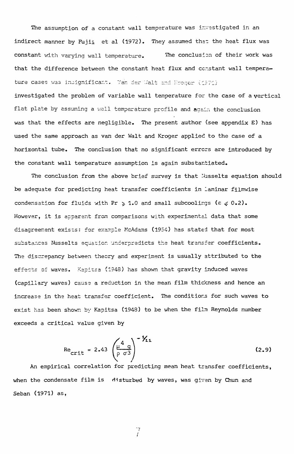
The assumption of a constant wall temperature was investigated in an
indirect manner by Fujii et al (1972). They assumed tha_ the heat flux was
constant with varying wall temperature. The conclusion of their work was
that the difference between the constant heat flux and constant wall tempera
ture cases was insignificant. Van der './alt and Kroger (IrT'l)
investigated the problem of variable wall temperature for the case of a vertical
flat plate by assuming a v;all temperature profile and again the conclusion
was that the effects are negligible. The present author (see appendix E) has
used the same approach as van der Walt and Kroger applied to the case of a
horizontal tube. The conclusion that no significant errors are introduced by
the constant wall temperature assumption is again substantiated.
The conclusion from the above brief survey is that Nusselts equation should
be adequate for predicting heat transfer coefficients in laminar filmwise
condensation for fluids with Pr ^ 1.0 and small subcoolings (e <: 0.2).
However, it is apparent from comparisons with experimental data that some
disagreement exists: for example McAdams (1954) has stated that for most
substances Nusselts equation uncerpredicts the heat transfer coefficients.
The discrepancy between theory and experiment is usually attributed to the
effects of waves. Kapitisa (1948) has shown that gravity induced waves
(capillary waves) cause a reduction in the mean film thickness and hence an
increase in the heat transfer coefficient. The conditions for such waves to
exist has been shown by Kapitsa (1948) to be when the film Reynolds number
exceeds a critical value given by
4 Re = 2.43 f ^—2.* v^— • i_ t. • *^ ~^ I ocrit I p cr3
\ vAn empirical correlation for predicting mean heat transfer coefficients,
when the condensate film is disturbed by waves, was given by Chun and
Seban (1971) as,
"7
/

= 0.8 (r/i)- (2.10)
The agreement between their experimental data and equation (2.10) written for
local coefficients was good.
2.3 Dropwise condensation
Sinee McAdams (1954) reported that heat -ransfer coefficients observed
during dropwise condensation of steam are several times larger' than those
obtained for filmwise condensation, a large amount of research, into
both the theoretical and experimental aspects. of 'dropwise condensation
has been undertaken.
The presently accepted mechanism for the process is as follows. The
vapour condenses as discrete drops on the surface; these drops grow by
coalescence and condensation until they are large enough to be removed by the
action of gravity or other body forces (e.g. vapour shear). When such drops
move they coalesce with other drops in -heir path, thus sweeping an area of the
surface clear of condensing drops. This enables the condensation process to
restart on the clear area. It is thus apparent that the dropwise condensation
process is cyclic in nature.
Several models for predicting the detailed processes involved have been
presented, an excellent review of the more important theoretical and experi
mental contributions in this very active field is given by Merte (1973).
2.4 Condensation of vapours of immiscible liquids
The following review is divided into three main sections. The first
covers experimental studies concerned with binary systems, the second work on
multicomponent systems and the third models and correlations.
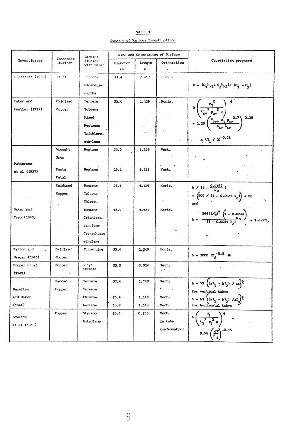
Not all of the published papers are reviewed in detail. Only the key
papers or those of particular interest are discussed. However, a summary of
the information contained in most papers can be found in Table 1.
C
Surr.ri[-y cf VaricMJs "rivcst j«pt ions
Investigator
:<::-^rld- (1933)
Baker and
>Ueller (1937)
Patterson
et al (1937)
-
Safcer and
Tsao (1340)
Pat tor. a=d
Feagaa Cl9£l)
Cooper et al
(1942)
Hazel ton
and Baker
(1544)
Edwards
et al (l9-'.o)
Condenser Surface
s..,,l
Oxidised
Copper
Wrought
Iron
Kuntz
Ketal
Oxidised
Copper
Oxidised
Copper
Copper
*,
Sanded
Copper
Copper
Liquids Studied with Water
F-r.,er.e
Cleaners—
naptha
Toluene
Kixed
Heptanes
Trichloro-
ethylene
Heptane
Heptane
Benzer.e
Toluene
Chlsro-
etr.yleae
T-trschloro
ethyl ene
Turpentine
3-tyl acetate
Senzen*
Toluene
Chloro-
benzene
Styreno
Butadiene
'Slr.c nr.d Orientation of Surface
Diameter
irjit
33.1
33.4
22.2
19.1
25.4
15.9
33.4
22.2
33.4
25.4
15.9
25.4
LengthD
2 * o»-* .'-•--
1.129
-
1.229
1.143
1.129
1.129
1.245
0.914
1.149
1.149
1.149
6.203
Orientation
Hori.-..
, Horiz.
-•
Vert.
^
Vert.
Horiz.
Horiz.
Horiz.
Vert.
Vert.
Vert.
.Vert.
Vert,
in tube
condensation
Correlation proposed
h - ^t^M* ^?^N2^ ^i * ®~>^
f M/ \ * '•
L I k*v3 P v2 9 j
f \f \i rt ' \• Ps^v 1 sv 1v fc 1 x / \ av av /
X (0^ / Q)"3'23
•
'
-
. . . 0.0167 .
/• " °° N. (500 / (1 _ O.OC35 V2 )J + 80
and
366(l/iy* M _ 0.0234 J h \ D 0 /<i - o.oo3> v^) T I.&V/QO
2 •
• . "^^
h - 3oco flrf~°- 5 ^
•
h - 79 [(aXl «. b X2 ) / J*
for vertical tubes
h » 51 >(a)>. * bXj) /aD V for horizontal tubes
/ M \ •}
-eSr'
Qy

TABLE 1 (Co^tinn->>1)
Investigator
Tobias and
Stoppel
(1954)
StepaneJc
and Standart
(1958)
.•
A. jeers and
;farr.er
(1952)
Syfces and
MarcheIZo
(1970)
Berr.harit
et al (1372)
Condenser Surface
Polished
Yellow
Brass
•
Copper
Polished
Brass
Liquids Studied with Water
Toluerte
Benzene
Cyclo-
hexane
Carbon
tetra-
chloride
n-Keptane
Benzene
Toluene
Diciiloro—
ethane
Chlcro-
berasene
Benserie
Heptane
Cartion-
•• •—»-
cMsrtdei
Oxidised
Copper
Gold
Toluer*
Carbon-
tetrs-
chl ssride
Jreon 112
Freon 113
Per^ioro-
ethyl erse
Size end Orientation of Surfaces
Diameternun
25.4
10.0
»
63.5
34.9
Lengthc
1.372
1.000
"
*
0.075
0.610
203.2 B» high by
7S.2 nsn wide
plate
Orientation
Vert.
Horiz.
Vert.
^
Horiz.
-
Vert.
-
Correlation proposed
C "• ( \ *« ^ 'h "^ / / 1 " ^H v^1 .v^ ^ ^
[ n A 0.21 }"l P2 k2 / /"*** **J J
h XH k -. 3 Pi2 S f6 - o- 723 TT-ZT-D — . a f J
x K,. (1 •*• K_ ^T-) •'Nt
h » fa^^Nl* bXJ\J / (a X- + bX_)^ ^
/" ^2 \ * / V*
M,, 3 2 J - 1-47 / u\kav pav g y V i y\ / x /
L h f« « B«» rA«. \0.67Rh « "w-i 11 — 0.8P.J ("T.) c ". A j
s. (~r 1 ^ -1he N.1^3 * ^ ^Tf j **
h « ^-iVfi* V3**N2'
•

TACf.E 1 (Contlnurd)
Investigator
Kawnski,
Ct al (1972)
Ponter and
Diah (1974)
i
V
.
-
Condenser Surface
Copper
Oxidised
Coppe.-
P.T.F.E.
Liquids Studied with UMter
B-n=CM
Toluene
Trlchloro-
ethylene
Benzene.
Carbon-
tetra-
ehloride
1,1,2
' Trichloro
ethyl ere
Cyclo-
hexane
Size flnd Orientation of 5urfnc<?
Dianeter
mm
6.2
9.5
16.0
23.6
t
Lerxjth
m
o.::si
O.C347
0.0397
0.813
-
Orientation
Horlz.
Horlz.
Correlation proposed •
.,'-.. - O.C^90 (Ga. :<u. Pr)^ (Re )"
V
For the copper tubex" .. _ -0.413
/ ( 4 U^.^ohe ' hNl ) 1 - a- 99 x 10 ||»av^
p-av -0,286
L kav Tf . JFor the P.T.F.E. tube
-o.o« {£**]L- -J
As shown by SyJees and f^rchello t!37D)
.52 / \3^2 -, t
» 0.0534 pV-t
.5 -1.3
17.3 x 10~10Pr, [ 1 + T ,- 1 V b\. 2 / \ 1
2.4.1. Experimental studies on binary systems
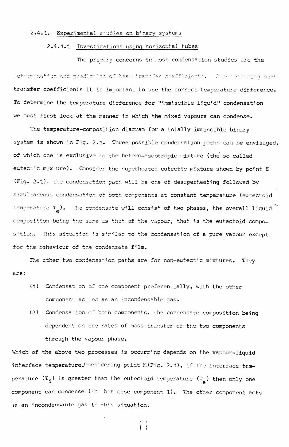
2.4.1.1 Investigations using horizontal tubes
The primary concerns in most condensation studies are the
transfer coefficients it is important to use the correct temperature difference.
To determine the temperature difference for "immiscible liquid" condensation
we must first lool< at the manner in which the mixed vapours can condense.
The temperature-composition diagram for a totally 5_mmiscible binary
system is shown in Fig. 2.1. Three possible condensation paths can be envisaged,
of which one is exclusive to the hetero-azeotropic mixture (the so called
eutectic mixture). Consider the superheated eutectic mixture shown by point E
(Fig. 2.1), the condensation path will be one of desuperheating followed by
simultaneous condensation of both components at constant temperature (eutectoid
temperature T ). The cor.csr.sate will consis- of two phases, the overall liquid
composition being the same as ths 4: of the vapour, that is the eutectoid compo—
s-'ticr;. This situation is similar to the condensation of a pure vapour except
for the behaviour of the condensate film.
The ether two condensation paths are for non-eutectic mixtures. They
-5 y^ •
(1) Condensation of one component preferentially, with the other
component acting as an incondensable gas.
(2) Condensation of both components, the condensate composition being
dependent on the rates of mass transfer of the two components
through the vapour phase.
Which of the above two processes is occurring depends on the vapour-liquid
interface temperature.Considering_pcint M(Fig. 2.1), if the interface tem
perature (T.) is greater than the eutectoid temperature (T ) then only one
component can condense On this case component 1). The other component acts
.is an •'ncondensable gas in this situation.

DEW POINT CURVE
LIQUID 1 + VAPOUR LIQUID 2
+VAPOUR
LIQUID 1
BUBBLE POINT CURVE
LIQUID 2
PURE COMPONENT IMPOSITION PURE COMPONENT 2
FIG. 2-1 TEMPERATURE COMPOSITION DIAGRAM FOR A
TOTALLY IMMISCIBLE BINARY SYSTEM. -
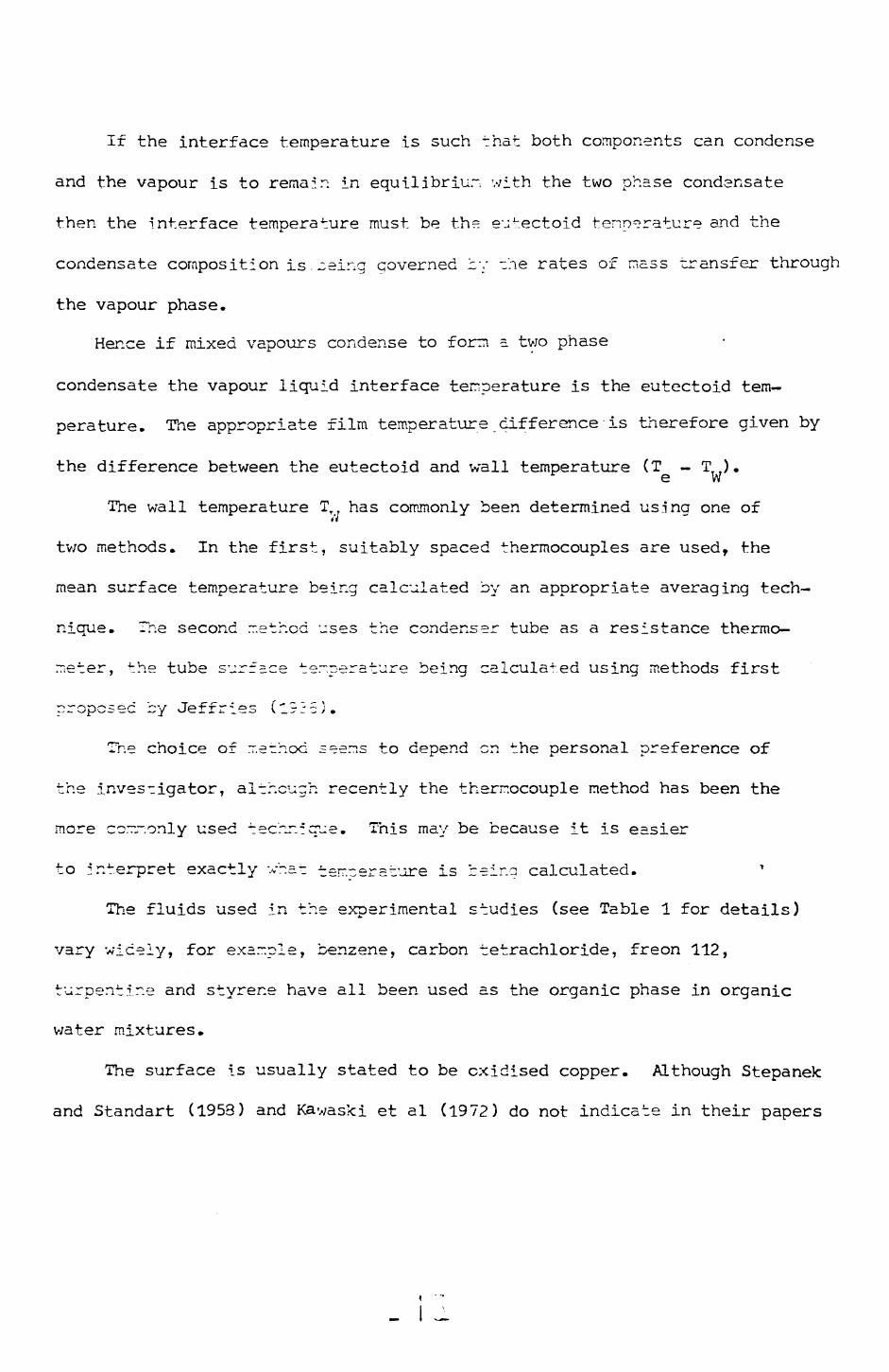
If the interface temperature is such that both components can condense
and the vapour is to remain in equilibrium with the two phase condansate
then the interface temperature must be the eutectoid temperature and the
condensate composition is.~eing governed 'z~: -he rates of mass transfer through
the vapour phase.
Hence if mixed vapours condense to form a two phase
condensate the vapour liquid interface temperature is the eutectoid tem
perature. The appropriate film temperature difference is therefore given by
the difference between the eutectoid and wall temperature (T - T ).^ e W
The wall temperature TTT has commonly been determined us.ina one ofti
two methods. In the first, suitably spaced thermocouples are used, the
mean surface temperature being calculated by an appropriate averaging tech
nique. The second method uses the condenser tube as a resistance thermo
meter, the tube surface temperature being calculated using methods first
proposed by Jef fries (1925).
The choice of method seems to depend en the personal preference of
the investigator, although recently the thermocouple method has been the
more commonly used technique. This may be because it is easier
to interpret exactly vhat temperature is being calculated.
The fluids used in the experimental studies (see Table 1 for details)
vary widely, for example, benzene, carbon tetrachloride, freon 112,
turpentine and styrene have all been used as the organic phase in organic
v/ater mixtures.
The surface is usually stated to be oxidised copper. Although Stepanek
and Standart (1953) and Kawaski et al (1972) do not indicate in their papers
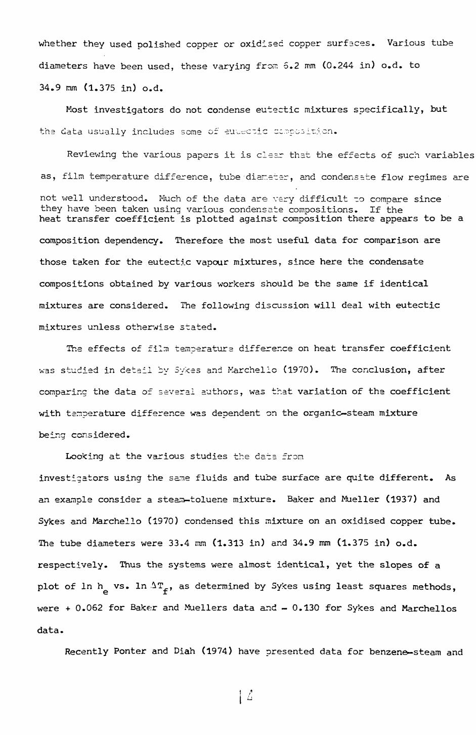
whether they used polished copper or oxidised copper surfaces. Various tube
diameters have been used, these varying from 5.2 mm (0.244 in) o.d. to
34.9 mm (1.375 in) o.d.
Most investigators do not condense eutectic mixtures specifically, but
the data usually includes some of •su^c-ic -c.T:pc3ir:vcn.
Reviewing the various papers it is clesr that the effects of such variables
as, film temperature difference, tube •diar.eter, and condensste flow regimes are
not well understood. Much of the data are very difficult -o compare sincethey have been taken using various condensate compositions. If theheat transfer coefficient is plotted against composition there appears to be a
composition dependency. Therefore the most useful data for comparison are
those taken for the eutectic vapour mixtures, since here the condensate
compositions obtained by various workers should be the same if identical
mixtures are considered. The following discussion will deal with eutectic
mixtures unless otherwise stated.
The effects of film temperature difference on heat transfer coefficient
was studied in detail by Sykes and Marchelio (1970). The conclusion, after
comparing the data of several authors, was that variation of the coefficient
with temperature difference was dependent on the organic—steam mixture
being considered.
Looking at the various studies the dots from
investigators using the same fluids and tube surface are quite different. As
an example consider a stear>-toluene mixture. Baker and Mueller (1937) and
Sykes and Marchelio (1970) condensed this mixture on an oxidised copper tube.
The tube diameters were 33.4 mm (1.313 in) and 34.9 mm (1.375 in) o.d.
respectively. Thus the systems were almost identical, yet the slopes of a
plot of In h vs. In AT , as determined by Sykes using least squares methods,
were + 0.062 for Bake.-r and Muellers data and - 0.130 for Sykes and Marchellos
data.
Recently Ponter and Diah (1974) have presented data for benzene—steam and

trichloroethylene-steam mixtures condensing :.- a 28.6 mm (1.125 in) o.d. oxid
ised copper tube and their results do not agree v/ith the results of Baker and
Mueller (1937) either. They suggested the discrepancy was because the tube
surface used by Baker and Mueller was not hcrrogeneous, that is the surface
properties and hence the condensation mec'r^r-is.- varied along the tub?.
The criterion used by Ponter and Diah (l?74) to indicate that the surface
was homogeneous appears to be when filmwise condensation of steam is consistently
produced over the whole length of the tube. ~f this is the case their
suggested explanation of the discrepancy between the two data sets is
complicated by the fact that Baker and Mueller (1937) also reported that they
too obtained filmwise condensation of steals on their tube. Thus there is still
doubt as to why these data sets are different.
The detailed effects of tube diameter on -he heat transfer coefficient are
far from certain. Both Kawas-ci et al (19~2) and Baker and Tsao (1940) have
stated that the heat transfer coefficient increases as the tube diameter
increases, this is contrary to the trend when condensing pure vapours or
vapour mixtures of miscible liquids. It thus appears that the tube diameter
has a marked effect on the heat transfer coefficient, exactly why there is such
an effect is unclear.
The differences in behaviour of the various systems may well be due to the
condensation mechanism, since quite different descriptions have been given by
various authors. The description given by Bater and Mueller (1937) is as
follows, the organic forms a film with the water forming standing drops on the
tube surface, these drops were "fairly stable and remained on the tube consider
able lengths of time and covered the greater portion of the tube". The
mechanism reported by Sykes and Marchello (19"3) is quite different, they
observed the water drops on the organic film, these drops eventually coalesced,
and finally formed a continuous water film which then flowed from the tube,
over the organic film. They also observed wh^t they termed secondary drainage,

that is the water film shedding from the side of the tube.
Thus we have two quite different descriptions of the condensation process
occurring on what apparently are similar tubes with the same fluids condensing.
It is unfortunate that Ponter and Diah (1974), Stepanek and Standart (1958) ar.c
Kawaski et al (1972) have not resorted th^ mechanism 5n the~r ex^eri^en^s, si: 1.--*.
the effects of the mechanism seem to influence the heat transfer coefficients.
It is also possible that the observed tube diameter effects are caused by
changes in mechanism. However, one cannot be certain of this explanation in
view of the laclc of descriptions in the relevant papers.
In a recent review Boyes and Ponter (1972) put forward various ideas as to
the hydrodynamic behaviour of organic—water mixtures. These ideas arose from
studies carried out with organio-water mixtures on a low energy surface
(P.T.F.EI.) and a high energy surface (copper). They state that "surface and
buoyancy forces play equally dominant roles in influencing hydrodynamic and
hence heat transfer behaviour".
In particular the value of the heat transfer coefficient is influenced by
the position of the va~er drops in the organic film. Thus, if the organic
phase density is less than the water density it would be expected that the
water crops would reside a~ the tube surface. Therefore, disturbing the film
and hence enhancing the heat transfer process by promoting better mixing.
If zhe organic is -he censer phase the water drops would float at the
vapour liquid interface and little or no enhancement would be expected.
However, a complicating factor is the relative growth rates of the film and
the drops, as the condensation rate is increased. If, as might be expected,
the drops grow faster than the film (i.e. by coalescence as well as condensa
tion) they could become large enough to penetrate the organic film, and again
enhancement of the heat transfer process would be expected.
Boyes and Ponter (1972) also proposed, that it should be possible to
increase the heat transfer coefficient by increasing the rate of removal of

the water drops, since this would increase the disturbance in the film.
Further it was suggested that using a P.T.F.E. coated surface would accomplish
this increased rate of removal»
Recently Ponter and Diah (1974) have conducted experiments using both an
oxidised copper and P.T.F.2. coatee copper tubes. The results obtain--:! from
this work tend to support the earlier ideas that greater heat transfer
coefficients would be obtainable using P.T.F.E. surfaces. Unfortunately most
of the enhancement goes into compensating for the resistance of the P.T.F.E.
coating, so that in fact the overall enhancement is not very great. However,
it does show that if sufficiently thin P.T.F.E. coatings were used an increase
in heat transfer coefficient might be obtained.
From the above discussion there are considerable
discrepancies between various data sets. It would appear that the mechanism
of the condensation process is important in trying to understand such
discrepancies, as are the effects of tube diameter. The reasons why the
mechanism is apperen-ciy different or. supposedly identical tube surfaces is at
creser.z unknov.r;. ur.lass cf cc^se ~r. oxidised copper surface does not give a
consistent oxide layer.
2.4.1.2 Investigerions using vertical surfaces
Although there have been several investigations using
vertical surfaces, there are relatively few studies which treat eutectic
mixtures, the study of Bemhardt et al (1972) being the only one to treat
eutectic mixtures exclusively.
Bernhardt et al (1972) studied the condensation of various organic steam
mixtures on a vertical gold plated copper plate. From their experiments it is
apparent that the heat transfer coefficient increases as the film temperature
difference decreases, this is contrary to the conclusion made by Hazelton and
Baker (1944) for the condensation of various mixtures on several different
diameter sanded copper tubes. They stated that the heat transfer coefficient
was independent of the temperature difference. However, this conclusion was
made on the basis of comparing data taken at various ccr.densate compositions
and film temperature differences. Since they do not ap;-ear to have systemati
cally varied the film temperature difference at cons tar.- condensate composi
tion it is possible that the effect of temperature difference is being masked
by a composition dependency.
The effect of the tube diameter has been shown by Baker and Hazelton (1944)
to be similar to the horizontal tube cas§, that is, the heat transfer
coefficient increases as the tube diameter increases.
The mechanism of the condensation process has been investigated in
considerable detail by Bernhardt et al (1972). They tock high speed cine
films of the process and also used conductivity probe and dye techniques to
identify the various phases. The description given by the above authors is as
follows. The organic phase forms a film in which water drops are suspended,
large standing water drops touch the metal surface and also protrude through
the film. Thus the bulk of the vapour contacts both liquids and both liquids
contact the solid. Very small mobile drops of organic were observed to be
present on the surface cf the large standing water drops. The origin of these
organic drops was uncertain, but the authors recognised the possibility that
they =re nucleating en the surface of the water drops, the nucleation sites
perhaps being microscopic dust particles entrained in the inlet vapours. These
dust particles are also used to explain the origin of the small water drops
floating on the film. The above description of the condensation mechanism
appears to have been the same for all condensation rates and for different
fluid systems.
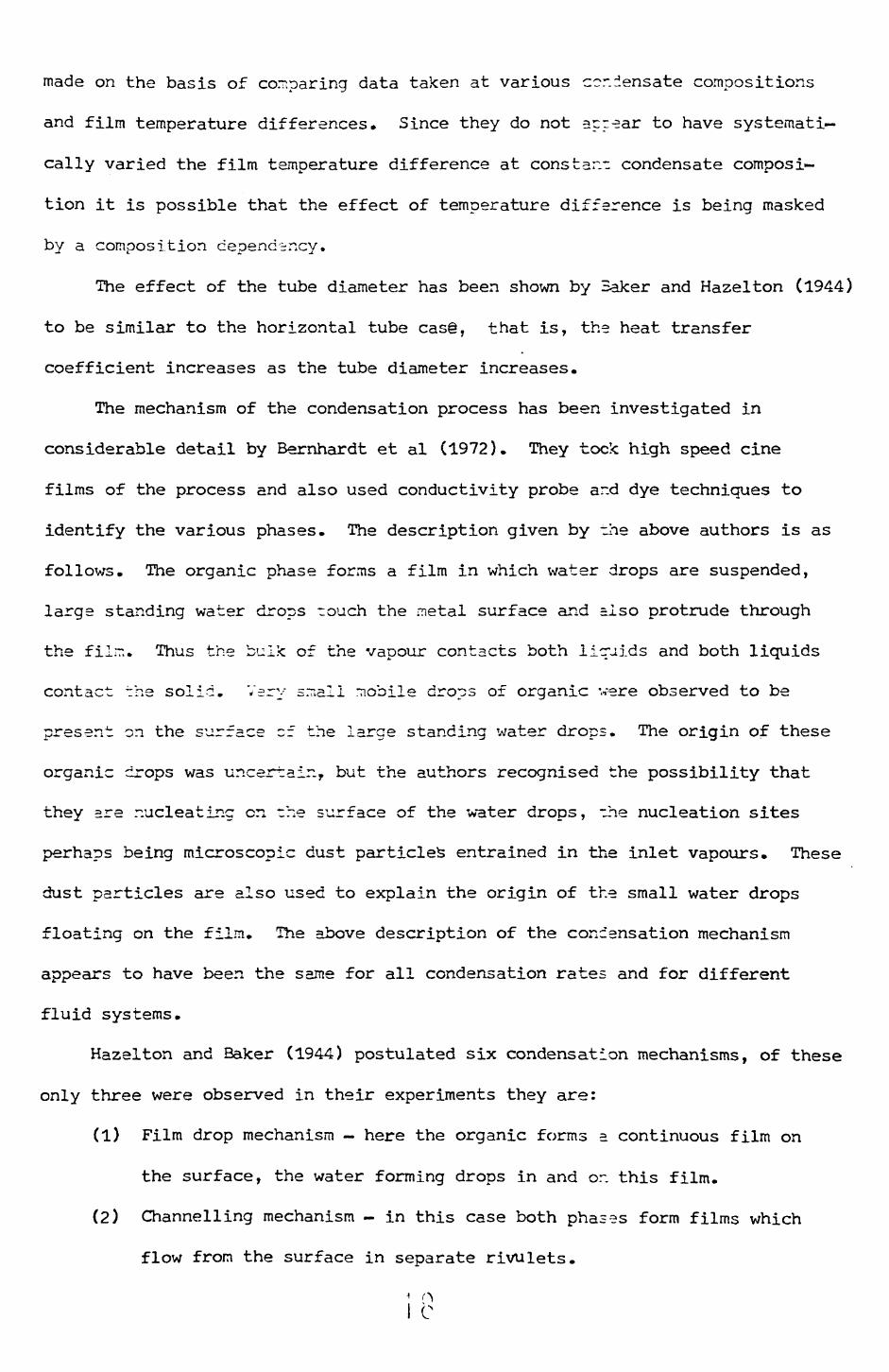
Hazelton and Baker (1944) postulated six condensation mechanisms, of these
only three were observed in their experiments they are:
(1) Film drop mechanism — here the organic forms a continuous film on
the surface, the water forming drops in and or. this film.
(2) Channelling mechanism - in this case both phases form films which
flow from the surface in separate rivulets.
' OI C
(3) 'The third mechanism is a mixture of the previous -wo.
From their experiments they found that the mechanism observed depended on
tube diameter. For the 15.9 mm (0.625 in) and 25.4 mm (1.C30 in) o.d. tubes
the mechanisms were predominantly of types (1) and (3) while for a 33.4 mm
(1.313 in) o.d, tube the mechanism \;?s of type (2). The authors sc^te that a
change of mechanism from types (l) to (3) has no marked effect on the heat
transfer coefficient whereas the channelling mechanism (type (2)) consistently
produced greater heat transfer coefficients than the other two mechanisms. No
explanation as to the cause of these effects was given.
Front the description of the condensation process, a channelling mechanism
can be as surged for the experiments of Tobias and Stoppel (lr-54) with a 25.4 mm(1.000 in) o.d. brass tube.
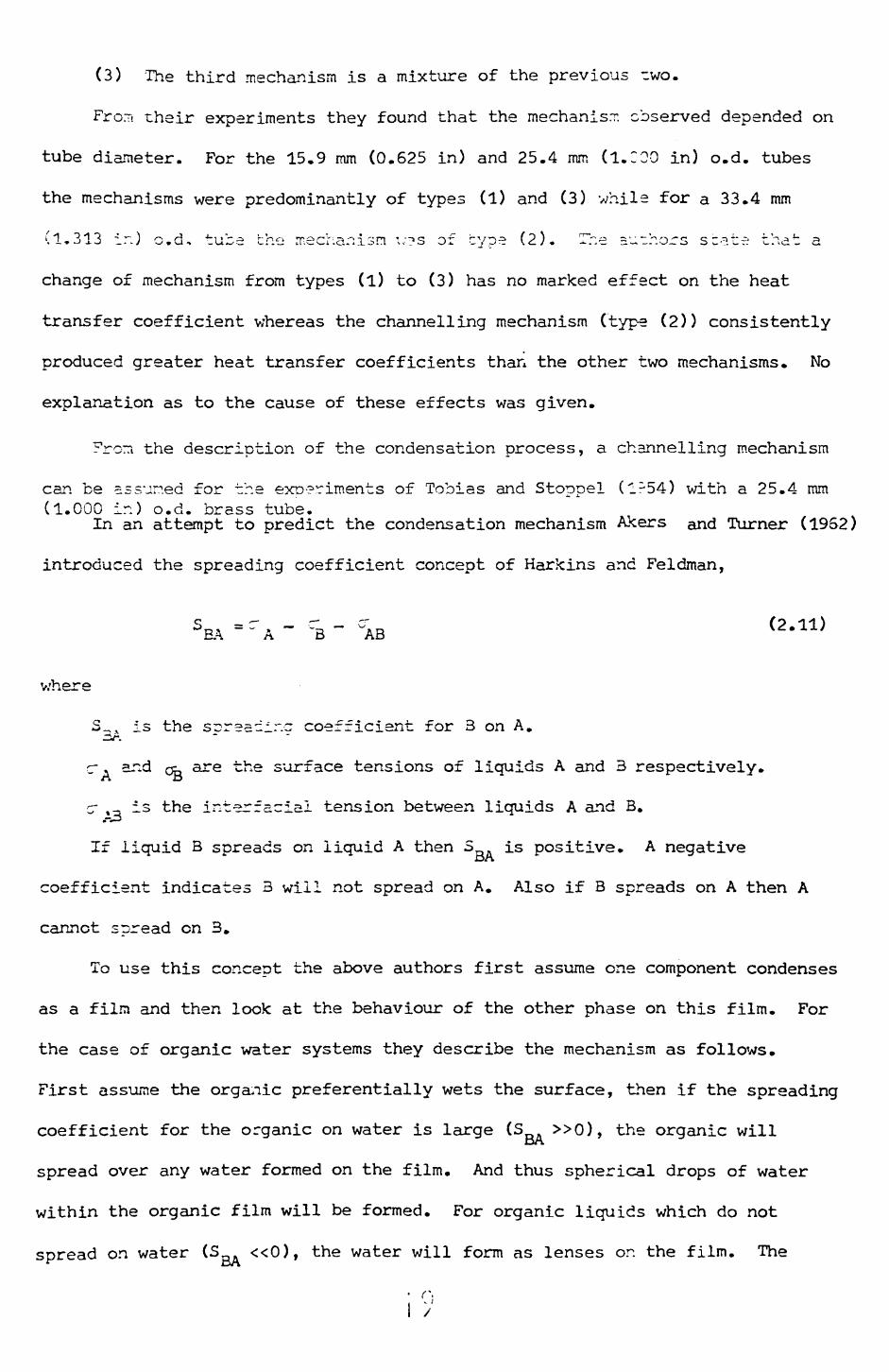
In an attempt to predict the condensation mechanism Akers and Turner (19S2)
introduced the spreading coefficient concept of Harkins and Feldman,
wn
S_, x is the spreading coefficient for 3 on A.
c ,. and Qg are the surface tensions of liquids A and 3 respectively.
cr % - is the interracial tension between liquids A and B. t-^
If liquid B spreads on liquid A then 3 is positive. A negative
coefficient indicates 3 will not spread on A. Also if B spreads on A then A
cannot spread on 3.
To use this concept the above authors first assume one component condenses
as a film and then look at the behaviour of the other phase on this film. For
the case of organic water systems they describe the mechanism as follows.
First assume the organic preferentially wets the surface, then if the spreading
coefficient for the organic on water is large (S »0), the organic willO/\
spread over any water formed on the film. And thus spherical drops of water
within the organic film will be formed. For organic liquids which do not
spread on water (Sg^ «0), the water will form as lenses on the film. The
i >'

mechanism of condensation is hence defender.- en the value of S . Also atDrt
high condensation rates or high v/ater vapcur concentrations the lenses coalesce
to form channels which flow over the organic film. At near zero spreading
coefficients the mechanism would be a mixture of the above processes.
A difficulty in using equation (2.11) ir to assign the correct valuer, of
surface tension to the various liquids, for example if the pure liquid surface
tensions are used for a benzene-water mixture 3 = 8.9, whereas if the surfaceOf\
tensions are those of the mutually saturated liquids S = -1.6. Adamson (1967)DA
states that for low surface tension liquids (e.g. organics) in contact with
water the final spreading coefficient will be close to zero or negative. Thus
the film-drop mechanism of Akers and Turner (1962) should not be realised in
practice. However, in the experiments reported by Akers and Turner (1962) all
three of their postulated mechanisms were observed.
The descriptions of the condensation mechanisms given above, although
apparently different are in fact quite similar, that is the standing drop type
mechanism observed by 3err.ha.rdt et al (1972) would be like the type (3)
mechanise described by Hazelton and Baker (1944) when the large water drops
rolled from the surface. Also if the watejr channels in Akers and Turners
(1962) description were touching the metal surface instead of the organic film
as described, this too would be similar to the other mechanisms.
It is apparent from the above discusslor. that the heat transfer coefficient
is dependent on condensation mechanism. This mechanism is influenced by tube
diameter, condensate composition, condensation rate and tube surface properties.
The manner in which these variables effect the mechanism is uncertain,
but it would seem that increasing the tube diameter changes the mechanism from
a film-drop to a channelling flow. An increase in the water concentration on
the tube also causes a film drop mechanism to revert to channelling flow.
Hazel ton and Baker (1944) have stated that changing from film drop to
channelling flow increases the heat transfer coefficient. Therefore the
• n

increase in heat transfer coefficient with increasing tube diameter can be
attributed to a change in mechanism. Whether this is also true for horizontal
tubes cannot be said but it seems likely.
2.4.2 Multicomponent systems
Very few papers have .--en published which deal with mulLiJompor.er.t
mixtures of vapours which form immiscible liquid phases ? two of the more recent
papers being due to Yusofova and Neikducht (1970) and Barnea and Mizrahi (1972),
Yusofoya and Neikducht (1970) condensed a steam petroleum mixture
("Shirvanneft") on the inside of a horizontal tube. Vapour velocities up to
15 m/s were used in these experiments. The correlation presented contains six
empirical constants and was derived specifically for the particular mixture
and experimental conditions studied.
Barnea and Mizrahi (1972) propose that for a kerosene steam mixture
h a (Q/A) " whereas the :.\;sselt ieper.der.ee is h a CO/A)"1"
The authors point out that the condensation process is extremely complex,
since the temperature ~r.d co~oosition are continuously changing along the
length of the condenser.
The paper does serve to point out the dangers in assuming a Nusselt type
dependence for predicting heat transfer coefficients for such complex mixtures.
2.4.3 Models and correlations
Most authors have presented some form of empirical correlation
and/or model of the condensation process. The correlations and models can be
classified into three basic types:
a) Homogeneous models, these usually use Nusselts equation with the
physical properties averaged in some manner.
b) Shared surface models, these assume that the two liquid phases form
seperate films which do not interfere with one another.
c) Other models, these usually start with specific assumptions on flow
patterns, or are derived empirically using intuitive mechanistic
L.

arguments.
Not all of the existing correlations will be mer.-l — ed in the following
sections since some of irie~ apply only to a single specific system. The
correlations not included can, however, be found in -able 1.
2.4.3.1 Hor.ccer.-ou3 models
The first correlation of this type v=.s presented by Baker
and Kuelier (1937), the equation is as follows,
21
.'32^ P gav r av
Jt
= 1.23
"*
C uPav ^1•• k1 '
av
"
Pav "
av
-3.23
(2.12)
where
k1 is a volume average of the pure liquid thernral conductivities,G V
C , p and \ ere weight averages of the specific heats, densities and
latent heats of the pure liquids respectively.
is the viscosity of rhe wall wetting phase.
Q is the heat Iced of the wall wetting phase.
Q is the total been load.
The constant in erua.ion (2.12) is not dimer_siunless and is valid
only for the British engineering system of units. This equation
ate for ~e/:er end Mueller's cv.r*
The equation preserved by Kawaski et al (1972) to correlate data obtained
using vapour crossflow ever various diameter tubes is,
Nu = O.C295 (Ga. Ku. Pr.) 4 Re \ (2.13)
This may be rewritten as
h = 0.0295_
(2.14)
where: k 1 , p ' , and ;^'_ ar ? volume averages of the pure liquid thermal

conductivities, densities and viscosities respectively.
X is the weight average of the pure liquid later.- heats of
vapourisation.
Re is the vapour crossflow Reynolds r.ur.ber.
This correlation predicts their ov/n dara quite veil, but has not been
tested against other data sets. However, since the correlation is specifically
for vapour crossflow it is not applicable ro the bulk: of the available
experimental data, where stagnant or near stagnant vapour conditions have been
used.
Akers and Turner (1952) presented the following general equation,
h2
g av ^= 1.47 L^i (2.15)
where }- Is the viscosity of the film forcing component
~ is the weirht =ver=ce of the pure liruid der_5ities •av " - r
k ' Is the vcl'-L-.e-rlc averacre of the cure liquid thermal conductivities av
r is the mass flow rate of the condensate per unit width of condenser
surface.
If equation (2.15) is compared with equation (2.2) it can be seen that it
is simply Nusselts equation with averaged physical properties. Akers and
Turner (1952) stated that: their equation was suitable fcr mechanisms of the
film drop or film lens type, since for these the major resistance to heat
transfer would be expected to be that of the organic filr,.
Bernhardt et al (1972) have shown that equation (2.15) predicts the
majority of the data from several authors to within en sverage error of — 20%.
2.4.3.2 Shared surface models
The first model of this !<ind was proposed by Kirkbride
(1933X.His equation is,
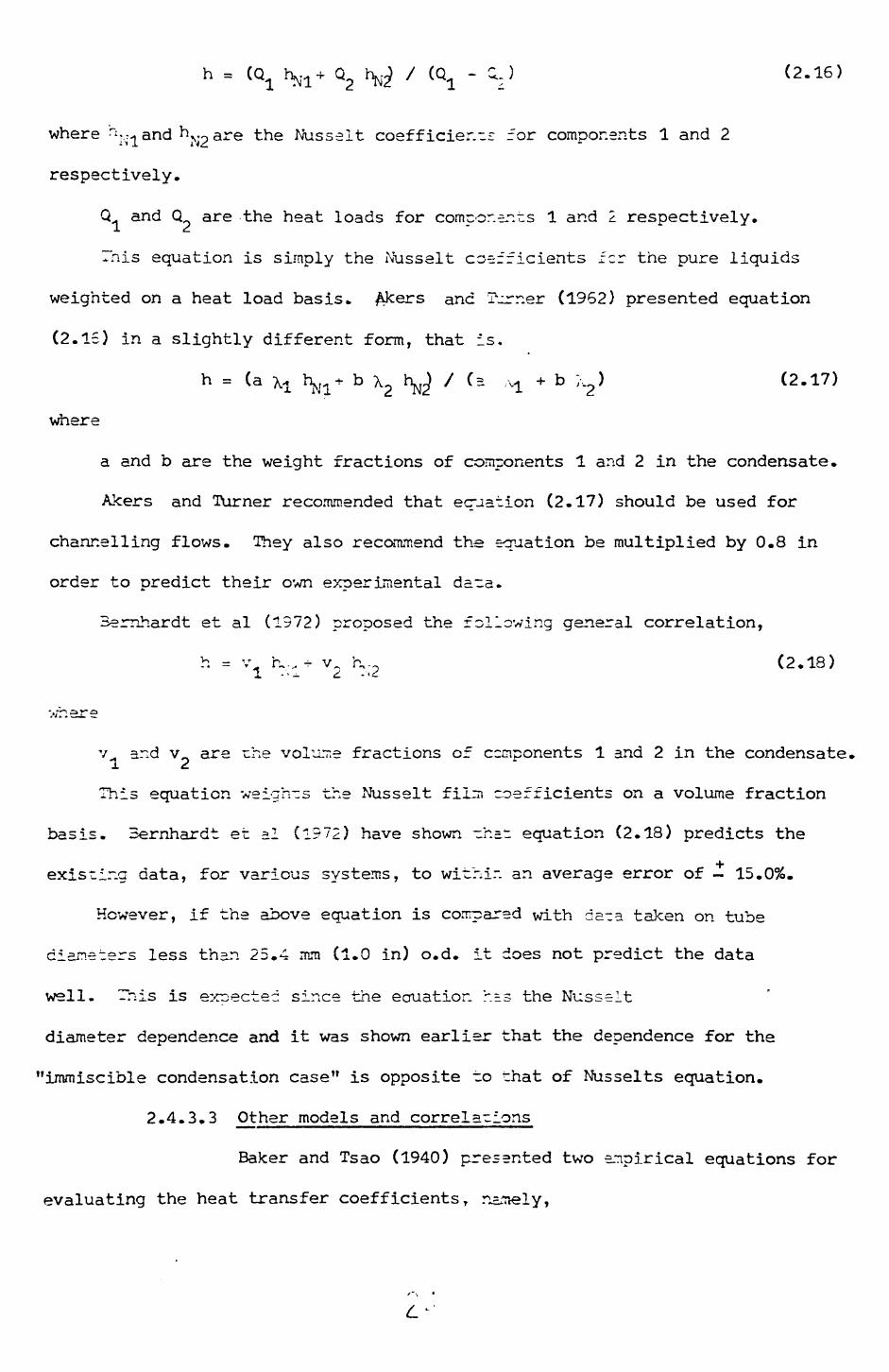
h = (Q hf Q h / (Q - ) (2.16)
where ri T.^and h^ are the Nusselt coefficients for components 1 and 2
respectively.
Q and Q are the heat loads for components 1 and 2 respectively.
This equation is simply the Nusselt coefficients fcr the pure liquids
weighted on a heat load basis. &kers and Turner (1962) presented equation
(2.15) in a slightly different form, that is.
h = (a xt h^* b X2 h^ / (= v± + b ;,,,) (2.17)
where
a and b are the weight fractions of components 1 arid 2 in the condensate.
Akers and Turner recommended that equation (2.17) should be used for
channelling flows. They also recommend the equation be multiplied by 0.8 in
order to predict their own experimental data.
Bemhardt et al (1972) proposed the following general correlation,
h = v. rv, - v^ K (2. IS)
v^ and v are rhe volume fractions of ccmponents 1 and 2 in the condensate.
This equation weights the Nusselt film coefficients on a volume fraction
basis. 3ernhardt et al (1972) have shown ~h=t equation (2.18) predicts the
existing -data, for various systems, to within an average error of - 15.0%.
However, if the above equation is compared with dB~a taken on tube
diameters less than 25.4 mm (1.0 in) o.d. it does not predict the data
well. This is expected since the ecruatior. r.= s the Nusselt
diameter dependence and it was shown earlier that the dependence for the
"immiscible condensation case" is opposite to that of Nusselts equation.
2.4.3.3 Other models and correlations
Baker and Tsao (1940) presented two empirical equations for
evaluating the heat transfer coefficients T namely,
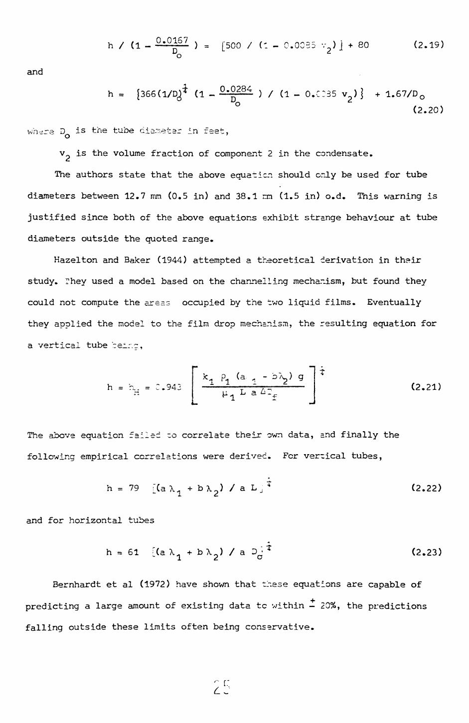
h / (1 - u p0/ ) = [500 / (1 - C.OCB5 v )] + 80 (2.19) o
and
h = [366C1/DJ (1 - u-^ ) / (1 - O.C!35 v ) j + 1.67/D. O, (2.20)
wh-re D is the tube diameter in feet, o
v is the volume fraction of component 2 in the condensate.
The authors state that the above equation should only be used for tube
diameters between 12.7 mm (0.5 in) and 38.1 m (1.5 in) o.d. This warning is
justified since both of the above equations exhibit strange behaviour at tube
diameters outside the quoted range.
Hazelton and Baker (1944) attempted a theoretical derivation in their
study. They used a model based on the channelling mechar_ism, but found they
could not compute the areas occupied by the two liquid films. Eventually
they applied the model to the film drop mech=nism, the resulting equation for
a vertical tube ceir.g,
h = a. = C.94; (2.21)
The above equation failed ~o correlate their own data, snd finally the
following empirical correlations were derived. For vertical tubes,
•
h = 79 i(a\« + b\ 2 ) / a L , T (2.22)
and for horizontal tubes
h = 61 [(a X a + b \ 2 ) / a DO« (2.23)
Bernhardt et al (1972) have shown that these equations are capable of
predicting a large amount of existing data tc v/ithin - 20%, the predictions
falling outside these limits often being conservative.
'- f."
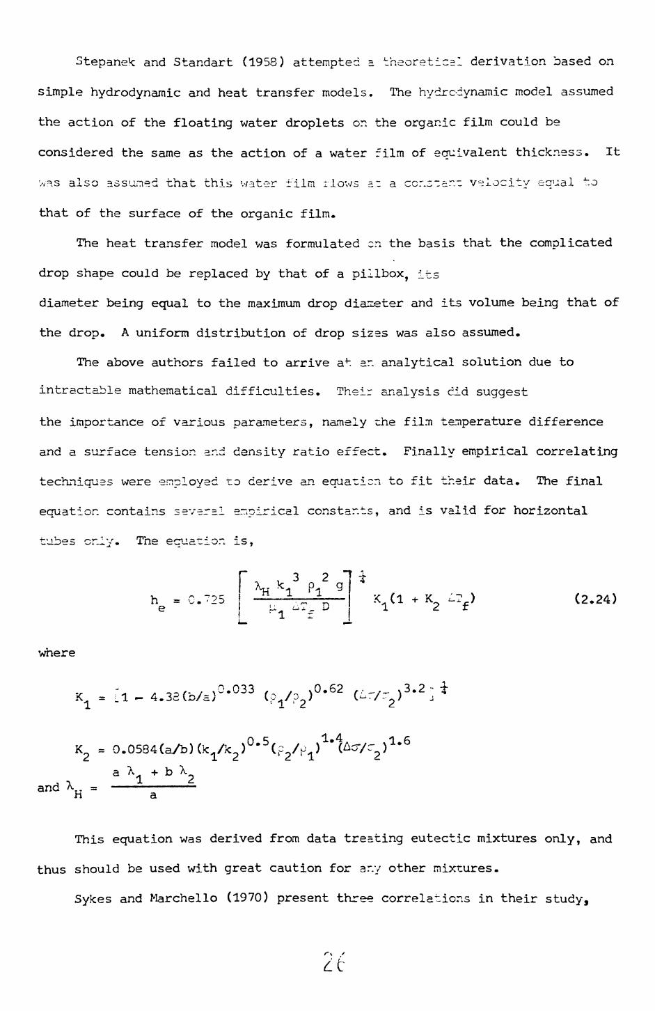
Stepanek and Standart (1958) attempted a theoretical derivation based on
simple hydrodynamic and heat transfer models. The hydrc-cynamic model assumed
the action of the floating water droplets on the organic film could be
considered the same as the action of a water film of equivalent thickness. It
>/=is also assumed that this water film rlows =.z a ccr.star.- velocity equal to
that of the surface of the organic film.
The heat transfer model was formulated en the basis that the complicated
drop shape could be replaced by that of a pillbox, its
diameter being equal to the maximum drop dianeter and its volume being that of
the drop. A uniform distribution of drop sizes was also assumed.
The above authors failed to arrive at ar. analytical solution due to
intractable mathematical difficulties. Their analysis did suggest
the importance of various parameters, namely zhe film temperature difference
and a surface tension and density ratio effect. Finally empirical correlating
techniques were employed to derive an equaricn to fit their data. The final
equation contains several empirical constants, and is valid for horizontal
tubes only. The equation is,•r
h = C.~25 e
~ 3 2 "*H *1 P! g
u ^T, D
iV1 K (2.24)
where
K = * i~f- / > - 4.3c;(i>/=}vO.62 ,,_.,. ,3.2 ; C^ A )
andrl
This equation was derived from data treating eutectic mixtures only, and
thus should be used with great caution for any other mixtures.
Sykes and Marchello (1970) present three correlations in their study,
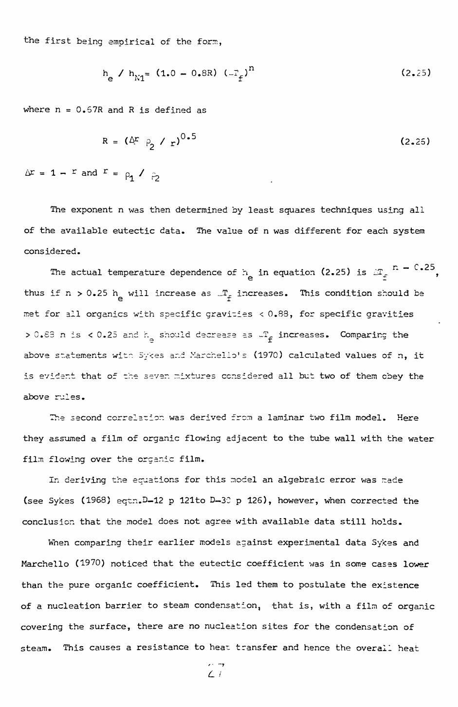
the first being empirical of the form,
h / h, M = (1.0 - 0.8R) C-IJ n (2.25)Q IM! f
where n = 0.57R and R is defined as
R =
= 1 - r and r = p / -
The exponent n was then determined by least squares techniques using all
of the available eutectic data. The value of n was different for each system
considered.
r — r 25 The actual temperature dependence of h in equation (2.25) is ^£, "~ ,
thus if n > 0.25 h will increase as _T, increases. This condition should bee r
met for all organics with specific gravities < 0.38, for specific gravities
> 0.83 n is < 0.25 and h should decrease ~s JT,_ increases. Comparinc thee r
above statements witr. 5y<es ar.d Marchelio' s (1970) calculated values of n, it
is evident that of the sever, mixtures considered all but two of them obey the
above rules.
The second correlation was derived from a laminar two film model. Here
they assumed a film of organic flowing adjacent to the tube wall with the water
film flowing over the organic film.
In deriving the equations for this model an algebraic error was ~ace
(see Sykes (1S68) eqtn.D-12 p 121to D-3C p 126), however, when corrected the
conclusion that the model does not agree with available data still holds.
When comparing their earlier models against experimental data Sykes and
Marchelio (1970) noticed that the eutectic coefficient was in some cases lower
than the pure organic coefficient. This led them to postulate the existence
of a nucleation barrier to steam condensation, that is, with a film of organic
covering the surface, there are no nucleation sites for the condensation of
steam. This causes a resistance to heat transfer and hence the overall heat
/ - -7
L I

transfer coefficient (from vapour to condenser wall) cculd conceivably fall
below that for the pure organic coefficient.
The final correlation derived from nucleation arguments was as follows,
1 / (X,
-1
(2.27)
where KS = [7.6 - 1.8 (Pr^ - "" x "* ~1
K. =-
17.3 x 10 Pr. (1
?r =
Oh = (j-r/p gD cr)?
e "f is the rate of nucleation of water drops on the organic film
5 = 0.035°"1
Or the three models proposed by SyJces and iMarchello (1970) the nucleation
model was the most successful over a wide range of systems, however, the
empirical expression (equation 2.25) did give a better fit for some systems.
The correlation presented by Tobias and Stoppel (1954) was obtained by
the use of dimensionless groups deduced from dimensional analysis, the final
equation being,
h =• V 1.0 - 545
mi P2 k2 m2 PI ka
0.50.21
(2.28)
where m and m are the mass rates of condensation for components 1 and 2
respectively.
The authors recommend that equation (2.28) should only be used within the
composition range 8-98% water.
Recently Marschall and Hickman (1973) presented = purely theoretical
study of the problem. They applied the conservation ecniations to both the
liquid and vapour phases in order to solve the concerns-ion problem. The flow
rr.odel assumed was the laminar two film model of Sykes and Marchello (1970),
Marschall and Hickman (1973) state that if the film temperature difference is
greater than 15 C then the heat transfer resistance in -he vapour boundary
layer may be neglected. Thus in this case the heat transfer resistance may be
obtained by considering the hydrodynamics of the filir only. Since Sykes and
Marchello (1970) have previously concluded that the two film model is inadequate,
then presumably the above model is also inadequate.
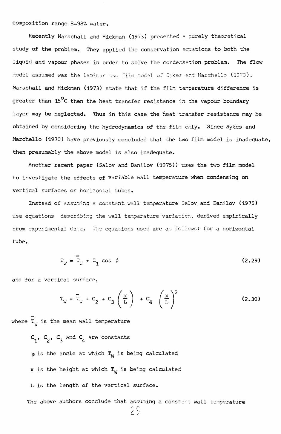
Another recent paper (Salov and Danilov (1975)) uses the two film model
to investigate the effects of variable wall temperature when condensing on
vertical surfaces or horizontal tubes.
Instead of assuming a constant wall temperature Salov and Danilov (1975)
use equations describing the wall temperature variation, derived empirically
from experimental data. The equations used are as fcllcws: for a horizontal
tube,
TW = ?.. T Z^ cos ? (2.29)
and for a vertical surface,
T,; = T.. + C + C [ f ) + C / £ 1 (2.30)«v '» 2 o I ij / 4
where T,, is the mean wall temperature
C , C , C and C are constants•L £ -3 ^x
0 is the angle at which T is being calculated
x is the height at which T is being calculated
L is the length of the vertical surface.
The above authors conclude that assuming a const?..-.-: wall temperature
2°
instead of a variable veil temperature has no significant effect en ".?
calculation of the mean heat transfer coefficient. Whether this conclusion
would hold if a different model of the heat transfer process were used is not
known.
Broadly the models and correlations above fall into tv/o m-?in ~re~s:
(1) Empirical — these are usually derived from limited experimental data.
(2) Models - these employ some model of the heat transfer process.
The correlations cf type (1) are usually restricted to the data sets used
in their derivation. Great care is needed if they are used outside these
limits.
Correlations of type (2), which use a model of the condensation process
should be capable of handling any situation for which the model is valid.
One of the main problems in trying to predict heat transfer coefficients
for immiscible systems is in determining the correct condensation, mechanism
and hence heat transfer model. As we have seen earlier the way in which
variables such as tube diE.-r.eter, tube surface properties, condensation rate and
condensste composition influence the condensation mechanism is not clearly
understood. In view of the above uncertainties it is not surprising -chat the
previously outlined r.ocels and correlations break: down under certain circum
stances. In fact it is perhaps surprising that equations (2.15), (2.13),
(2.22) and (2.23) are so successful.
2.5 Conclusions
(1) The heat transfer coefficient obtained during the condensation of
vapours of imiscible liquids depends on the mechanism of condensa
tion.
(2) The condensation mechanism is influenced by the tube dicimeter, tube
surface properties, condensation rate and condensate conposition;
the way in which these variables effect the mechanism is not clearly
understood.
(3) Difficulties in the nucleacion of water drops onto the organic film could
be important. - , N

(4) Most of the correlations ar.d models proposed are limited to *r.e
experimental data or assumed mechanism used in their derivation.
Because of the difficulties in determining the condensation rechanism
the choice of the appropriate heat transfer r.odel is difficu.t.
Squat ions (2.15), (2.13), (2.22) ar.d (2.22) ?.pp-=r to be —- b-sst
:co%
in certain circumstances.
i-j<4>-ia v-j_vjii» \IL.-~I* v£.J.o/, v r. i; ^..-^ \^.<^^> ;-^-'_--. LU ^-± _..— --
general correlations, although they too can be out by over — 1(

Chapter 3
Apparatus and Procedure
3.1 Introduction
It is common industrial practice to use horizontal shell and tube
condensers % The design of such units for vapours of immiscible liquids is not
well understood, nor are the mechanisms of bhe condensation process. The
present experimental facility has been designed in an attempt to improve this
understanding. A single tube horizontal shell and tube condenser was selected
for this study because it provides a relatively simple means of obtaining the
necessary heat transfer and mechanistic data needed to improve our understand
ing of the condensation process.
A flowsheet and photograph of the apparatus are shown in Fig. 3.1 and 3. la
respectively, the essential features are:-
(1) Vapouriser circuit
(2) Test section
(3) Condensate circuit
(4) Cooling water circuit
(5) Condenser tube
(6) Total condenser
The above items will now be described in detaili
3.2 Apparatus
It was known at the beginning of the present study that the liquids used
would be both toxic and in some cases highly inflammable, The first considera
tion in designing the rig was thus safety. The laboratory in which the
apparatus was built is fully flameproofed, and hence all electrical equipment
and spark inducing devices had to be either eliminated or flameproofed.
Ventillation is provided by large fans which suck air from a set of ducts at
floor level. In case of fire the laboratory is protected by an automatic fire
Lab.
Wall
C.-
J
Ven
t Li
no
Co
olin
gW
ater
Out
Sec
tion
Man
omet
er
Tot
al
Con
dens
erO
rific
e
Pla
te
IIT
est
Se
ctio
n^
Ste
am
Ste
am
Con
dens
ate
e Lin
e
Con
dens
ate
Sep
era
tor
Coo
ling
Wa
ter
Pre
he
ate
rS
team
Li
neS
team
C
onde
nsat
e Li
ne
Res
ervo
irR
eser
voir
Coo
ling
Wat
er
Sto
rage
T
an
k
I Ou
tsid
e• Coolin
g
Wate
r In
__________
__ _
_
_______ _
J L
abora
tory
FIG
. 3-
1.
FLO
W
DIA
GR
AM
O
F TH
E
AP
PA
RA
TU
S.

Fig. 3.la OVERALL VIEW of the APPARATUS

fighting system,which will flood the laboratory with carbon dioxide gas if
tripped. Under normal working conditions the system is operated manually,
since there is a danger that any personel in the laboratory when the system is
triggered will suffocate.
3.2.1 V'apouriser circuit - Liquid is pumped from the two stainless steel
reservoirs (approx. capacity 60 litres each) by 0.56 kW compressed air operated
gear pumps. The flowrate of each liquid is controlled by a globe valve and is
metered by a rotaroeter (accuracy +_ 2-o%).
The vapouriser consists of three jacketted copper tubes. The process
fluid flows through the inner (2.54 cm i.d.) tube, whilst steam condensing in
the annular space between the inner and outer jacket (3.81 cm i.d.) provides
the heat to boil the liquids. Twisted metal tapes were installed in the inner
tubes, these ensure good heat transfer and hence total vapourisation of the
liquids.
All three tubes are independently heated, their respective lengths being
1.2 ro, 0.6 m and 0.5 m, giving a maximum heated length of 2.3 m.
The resulting vapours are then delivered to the test section by a 2.54 cm
i.d. copper pipe. The whole of the vapouriser circuit is lagged with
fibreglass.
3.2.2 Test Section - The condenser tubing runs through the centre of a
21 cm i.d. stainless steel shell 92 cms in length. The shell has three
windows (61 cms x 5.0 cm) spaced 120 apart (see Fig»3-2), these are provided
so that observation along the whole length of the condensing surface is
possible. Special heat resistant glass was used for these windows.
The incoming vapours enter the shell through a bent copper tube 1.3 cm
i.d., (see Fig.3.2) sixteen 0.7 cm diameter holes provide the vapour flow area.
The purpose of this tube is to ensure that the vapour flows parallel to the
condenser tube.
Condensate is collected from the central portion of the tube in an

Win
dow
s
Va
po
ur
Inle
t P
ipe
Shel
lT
rou
gh
Con
dens
er
Tub
e
FIG
. 3-2
. D
IAG
RA
M
OF
THE
T
ES
T
SE
CT
ION
.

inclined trough (61 cr^s x 5.0 cms), it passes out of the test section via a
1.3 cm i.d. copper pipe. The condensate collected in the shell also drains
through a 1.3 cm i.d. copper pipe.
Excess vapours ar.c condensate are removed at the end of the shell
opposite to the vapour Inlet. The excess vapours pass through a 2.54 cm i.d.
copper pipe to the total condenser.
The vapour temperatures at the inlet and outlet ends of the shell are
measured by stainless steel sheathed chromel—alumel thermocouples. Test
section pressure is determined by a pressure gauge and a water manometer. The
shell is also lagged wrth fibreglass.
3.2.3 Condensate circuit - The condensate passes from the shell drain line
into either a sampling vessel or through a water cooled line to the separator.
A glass vessel 23 cms o.d. and 38 cms in height is provided as the separator,
When running the rig in practice the condensate is drained from the separator
into storage tanks where it is allowed to settle before being returned to
.the main reservoirs.
3.2.4 Cooling Water circuit - Cooling water is pumped from a large
storage tank via a 7.5 :<W centrifugal pump through a 5.0 cm i.d. copper pipe to
the preheater. From the preheater water is delivered to the test section at g
set temperature autom=iicc.lly controlled to +^ O.SoC. Heating is provided
by condensation of stears in the tubes of a shell and U tube condenser. The
unit is approximately 1.5 ~ long and is rated by the manufacturer at 150 kW.
A thermocouple in -he cooling water outlet pipe provides a signal to a
feedback control loop which adjusts the steam valve setting. The controller
operates in the proportional + integral mode.
r
From the test section the water flows back to the storage tank through an
8.0 cm i.d. galvanised iron pipe. The water flowrate is determined by a 3.06
cm orifice plate situated in the line. The pressure drop across the orifice
3

plate is measured bv =r. inverted water manometer, the orifice plate was
calibrated by-measuring ~he v;ater flowrate (by collecting a known weight in a
known time) and noting the corresponding manometer reading.
The cooling water temperature is determined at the inlet and outlet ends
of the test section by two stainless steel sheathed chromel-alumel thermocouples,
these were calibrated acains~ National Physical Laboratory (N.P.L.) tested
mercury in glass thermometers and estimated to be accurate to jf 0.1 C. An
independent check on the cooling water temperature rise is made by using a
system of four thermocouples arranged to give the difference in temperature at
the inlet and outlet ends of the test section. This device was calibrated
against two N.P.L. calibrated platinum resistance thermometers and has an
Qestimated accuracy of jr_ 0.05 C.
All thermocouples are connected to a "Modulog" data logging system,
capable of handling up to fifty channels of input data.
3.2.5 Condenser tube - Copper tube 2.54 cm o.d., 1.905 cm i.d. and
122 cms long is used ir. the test section. Only 61.0 cms of tube are used when
taking experimental data. Two such tubes were manufactured, the first had nine
thermocouples (copper-constantan) and the second twelve arranged as shown in
Fig. 3.3.
The thermocouples were embedded in the tube wall in the following manner.
A small copper plug was soldered to the end of a constantan wire and the
surface of the plug was copper plated. The plug was then soldered into a hole
drilled in the tube wall, the thermocouple leads being taken out through the
centre of the tube. Fig. 3.3 shows the details of the above procedure. When
all the thermocouples had been installed the plugs were filed flush with the
tube surface. A copper wire soldered to one end of the copper tube provides
the other thermocouple lead.
In order to provide a condenser with uniform surface properties the
following procedures were adopted. The nine thermocouple tube was polished
with emergy paper, the final finish being achieved with grade four polishing
paper* It was then thorough .y washed with acetone and distilled water.
- 38 -
The
rmoc
oupl
e P
ositi
ons
on
Nin
e T
herm
ocou
ple
Tube
The
rmoc
oupl
e P
osi
tion
s on
T
wel
ve
The
rmoc
oupl
e Tu
be
Out
side
Wall
P.T
.F.E
. 'In
sula
tion
Copp
er
Plug
Const
anta
n
Wire
Sol
der
Coo
ling
Wa
ter
FIG
. 3-
3.
DE
TA
ILS
O
F TH
ER
MO
CO
UP
LE
INS
TALA
TIO
N,

Before taking any experiment E.1 measurements the tube v;=s used as a steam
condenser until it consistently produced filmwise condensation over the
whole tube length, this process took twenty days.
The twelve thermocouple tube v;as first copper placed and then gold
plated before use. T'-.ls procedure was adopted because B. gold planed surface
would not be affected by any of the chemicals used in riis study and therefore
a reproducable surface would be obtained.
3.2.6 Thermocouple calibration - The thermocouples in the condenser tubes
were calibrated in two ways; in the first method the tube was placed in a glass
jacket and water from a constant temperature bath was passed through the jacket
and tube back to the bath. Four previously calibrated chromel-alumel thermo
couples were used to measure the water temperature. All of the condenser tube
and water thermocouple outputs were recorded by the "Modulog" data logger, and
printed out by an I.B.M. typewriter. The sampling speed was usually set at
1 channel/s but could be increased to 2 ch/s if necessary, the sensitivity of
the data logger was to within _+ lymV and the estimated accuracy of the calibra
tion was _+ 0.2 C. The second calibration method was =n "in situ" procedure
developed to check that no drift occurs during operation. In this method the
appratus is operated with only the cooling water supply turned on, since the
temperature at the inlet and outlet end of the tube are known. The heat lost
through the tube by convection and radiation can be estimated, hence the error
in assuming the water temperature is the same as the tube surface temperature
can be calculated. The accuracy of this method has been estimated at better
than +_ 0.2 C.
3.2.7 Total condenser - 'The excess vapour from The test section flows
through a 2.54 cm i.d.. copper pipe into the total condenser. This consists of
3.6 m of jacketed copper tube. Vapour flows in the annular space between the
jacket (3.81 cm i.d.) and the inner tube (2.54 cm i.e.), while cooling water
from the mains flows through the tube. A 1.27 cm i.e. copper tube fixed into
the top section of the total condenser acts as a vent line for any incondensable
gases.
- 40 -
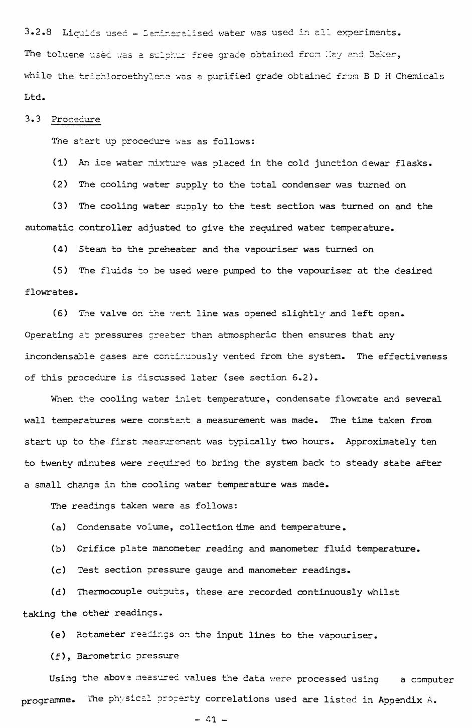
3.2.8 Liquids used - l~:r.ir.£r = lised water was used in all experiments.
The toluene used ;;as a sulcr.ur free grade obtained from Hay and Baker,
while the trichloroethylene was a purified grade obtained from B D H Chemicals
Ltd.
3.3 Procedure
The start up procedure v;as as follows:
(1) An ice water mixture was placed in the cold junction dewar flasks.
(2) The cooling water supply to the total condenser was turned on
(3) The cooling water supply to the test section was turned on and the
automatic controller adjusted to give the required water temperature.
(4) Steam to the preheater and the vapour iser was turned on
(5) The fluids to be used were pumped to the vapouriser at the desired
flowrates.
(6) The valve on the ver.t line was opened slightly .and left open.
Operating at pressures greater than atmospheric then ensures that any
incondensable gases are continuously vented from the system. The effectiveness
of this procedure is discussed later (see section 6.2).
When the cooling water inlet temperature, condensate flowrate and several
wall temperatures were constant a measurement was made. The time taken from
start up to the first measurement was typically two hours. Approximately ten
to twenty minutes were required to bring the system back to steady state after
a small change in the cooling water temperature was made.
The readings taken were as follows:
(a) Condensate volume, collection time and temperature.
(b) Orifice plate manometer reading and manometer fluid temperature.
(c) Test section pressure gauge and manometer readings.
(d) Thermocouple outputs, these are recorded continuously whilst
taking the other readings.
(e) Rotameter readings on the input lines to the vapouriser.
(f), Barometric pressure
Using the above measured values the data v;ere processed using a computer
programme. The physical property correlations used are listed in Appendix A.

Chapter 4
Results
4.1 Introduction
In this chapter ~.e experimental results are presented. The first
s-2ctio;i deals with the p-j_re component data and the second binary mixture
data. All of the data presented below in graphical form are tabulated
in detail in Appendix 3. A detailed error analysis of the results is given
in Appendix G. From the analysis it can be seen that the measured heat
transfer coefficients are accurate to within +_ 15.0% for film temperature
differences greater than approximately 4.0°C.
4.2 Pure component data
The pure components used were steam, toluene and trichloroethylene;
the tube used was the oxidised copper tube described earlier (Chapter
3 section 3.2.5). All three systems condensed in the filmwise manner.
The steam data are shown in figure 4.1 and tabulated in table Bl, toluene
data are*shown in figure 4.2 and tabulated in table B 2 while the trichloro—
ethylene data are shown in figure 4.3 and tabulated in table B 3.
4.3 Immiscible liciuic data
4.3.1 Heat transfer fata
The mixtures usec vere steam—toluene and steam—trichloroethylene.
Both mixtures were condensed on the oxidised copper arid gold plated tubes.
The steam-toluene data for the oxidised copper and gold plated tubes
are shown in figures 4.4 and 4.5, and tabulated in table 3 4 and B 5
respectively, while the steam-trichloroethylene data for the oxidised
copper tube and gold plated tube are shown in figures 4.6 and 4.7, and
tabulated in table 3 5 and 3 7 respectively.
4.3.2 Observed flow rattems
The flow pattern observed depended on the tube surface being used.
For the oxidised copper tube the mechanism for the steam-toluene mixture
was as follows. Both phases formed irregular films on the tube surfaca
42

(see figure 4.S). The orcrar.ic film contained v/ater drops which adhered
to the tube surface. Or. or in these water drops smaller organic drops
were observed. These were moving very rapidly. Also the water film had
organic drops in it, however, in this case the drops moved freely with
the water film.
The steam-trichloroethylene condensing or. the oxidised copper
surface gave a flow pattern similar to the one described above (see
figure 4.9). However, in this case the rivulets were much more clearly
defined forming discrete bands on the condenser surface.
The flow pattern for the steam-toluene mixture condensing on the
gold plated tube was as follows. The toluene formed a film, and the water
standing drops within this film. Rivulets of water were also observed
(see figure 4.10). Small water drops flowed on or in the organic films.
Again small organic drops flowed on or in the standing water drops.
Further it was observed that when a standing drop drained from the surface
a rivulet was formed, -his contained flowing organic drops. Another
phenomenon was the existence of patches under the water drops, these
disappeared when the organic film flowed over them.
The flow regime for the steam-trichloroethylene mixture on the gold
plated tube was similar, to that for the steam-toluene mixture, however,
in this case their were no continuous rivulets and far more standing
drops (Figure 4.11).
When the larger standing water drops drained a track of small water
drops was left in their wake.
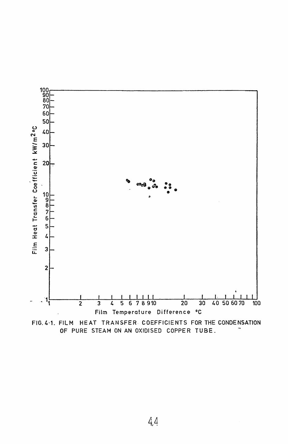
100r9080706050
oo
<M
Ca
30
c 20 o;
o" 10 fc g««- o (/) O
76
E 3
/1<1 2 3 4 5 6 78910 20 30 40 50 60 70 100Film Temperature Difference °C
FIG.4-1. FILM HEAT TRANSFER COEFFICIENTS FOR THE CONDENSATION OF PURE STEAM ON AN OXIDISED COPPER TUBE.
44 i/ •
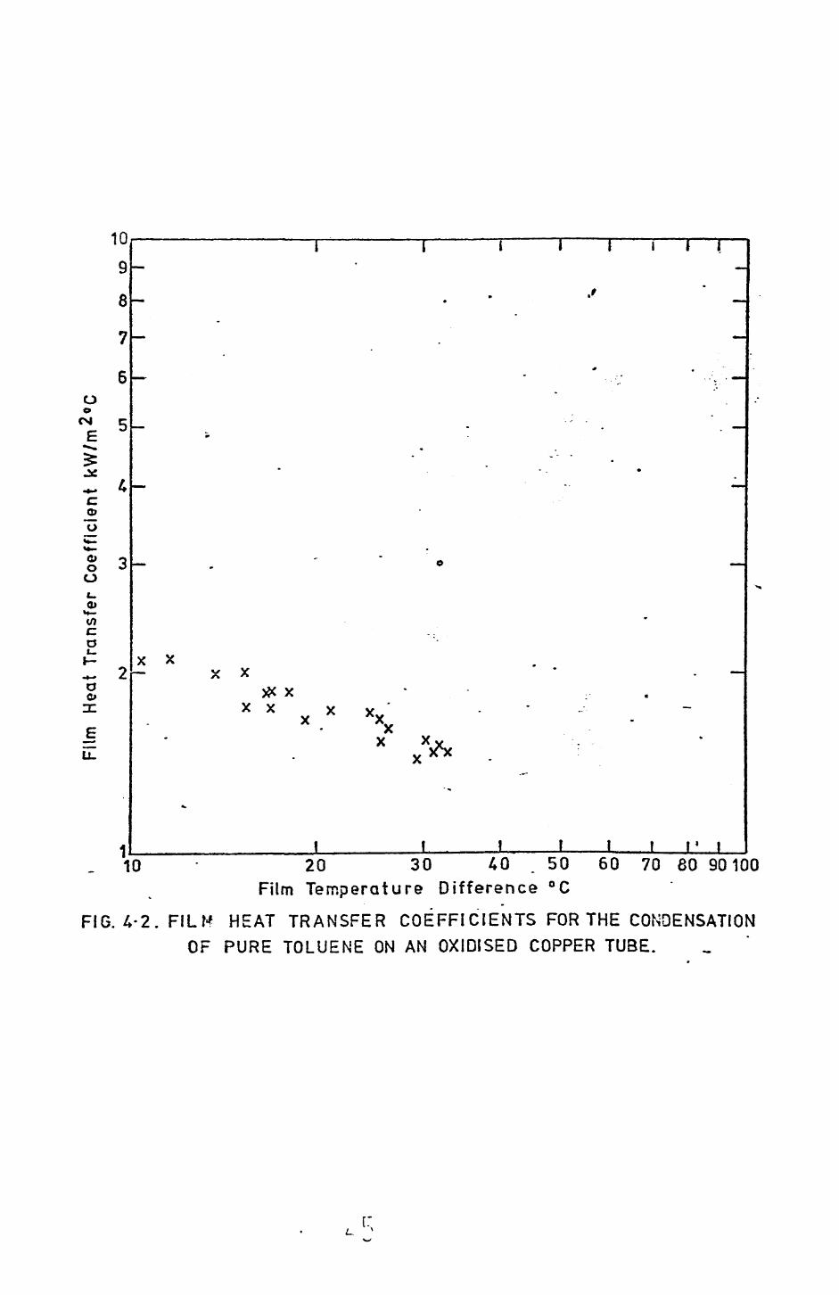
10
9
8
7
6 oo
<NJ C
3:
_§ 01
1
C 0»
O O Oi_ 0)
^2- xxO o, x
xx
I i I T
xx x xxX
Jl_______!_____f , f———l i10 - 20 30 40 . 50 60 70 60 90100
Film Temperature Difference °C
FIG. A-2.FILH HEAT TRANSFER COEFFICIENTS FOR THE CONDENSATION OF PURE TOLUENE ON AN OXIDISED COPPER TUBE.
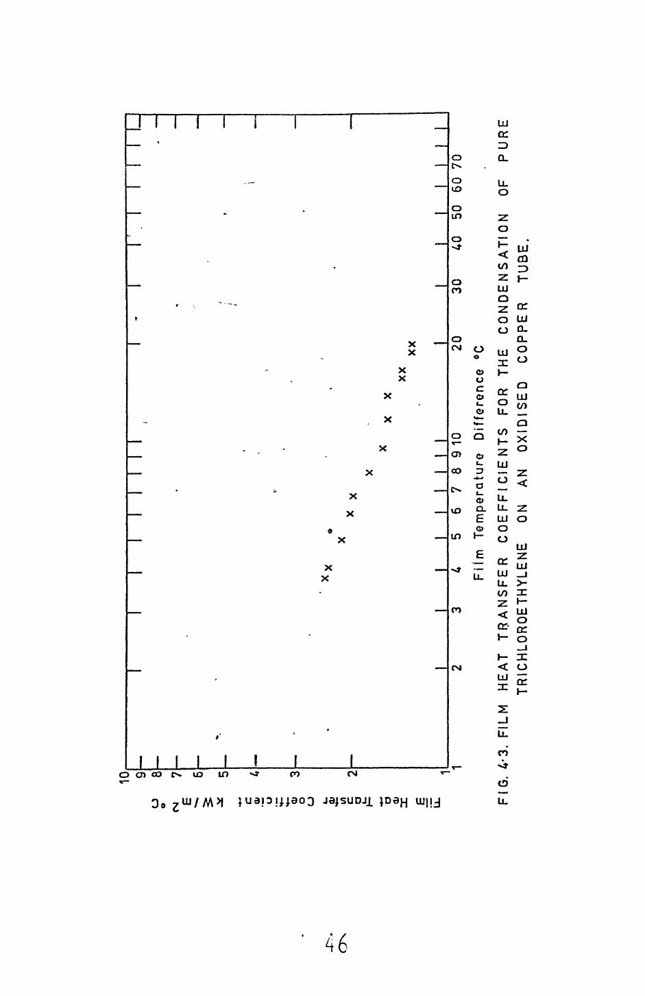
u o
(N
E c tt>
U c a £
"o X E iZ
10 9 8 7 6 1 1
Fl
II
1 I
I I
I I
I
I I
I I
I I
I
X X
XX
XX 1
1I_
_I_
I II
I30
40
50
60
70
2 3456
78
91
0
20
Film
T
empe
ratu
re
Diff
eren
ce
°C
G. 4
-3.
FILM
H
EA
T T
RA
NS
FE
R
CO
EF
FIC
IEN
TS
FO
R
THE
C
ON
DE
NS
AT
ION
TR
ICH
LOR
OE
THY
LEN
E
ON
AN
OX
IDIS
ED
C
OP
PE
R
TU
BE
.O
F P
UR
E
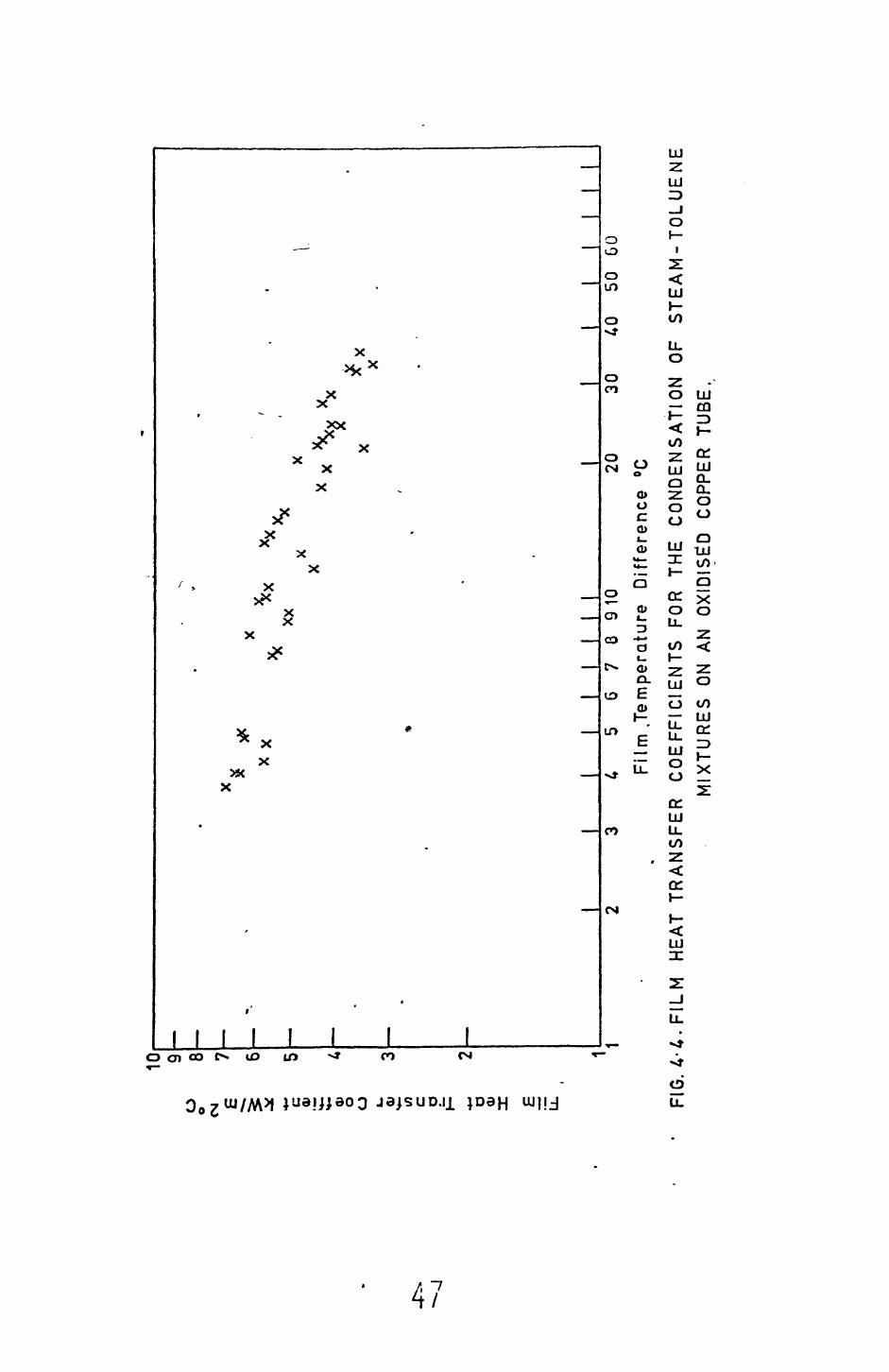
o o
CM
E 0) OJ o o c a a> £
iZ
10 g 8 7 6 5 2
FIG
.
1I
I
x x
XX
I I
I I
I M
1I
I I
I30
40
50
GO2
3 4
5G
78
91
0
20
Film
.T
empe
ratu
re
Diff
eren
ce
°C
.FIL
M
HEA
T TR
AN
SFE
R
CO
EFF
ICIE
NTS
FO
R
THE
CO
ND
EN
SA
TIO
N
OF
ST
EA
M-T
OLU
EN
EM
IXTU
RE
S
ON A
N O
XID
ISED
CO
PPER
TU
BE.

oo
o o E | c o 0) o o 0)
«*- (/) c.
a o <D X
10 9 8 7 6 5 1I
I
o .
o
o o
%
0
I I
I I
I I I
1I
1_
I !
L I
I1
2 3
A 5
6 7
8 9
10
20
30
40
50
60 7
0 80
Film
Te
mpe
ratu
re
Diff
eren
ce °
C
FIG
.4-5
. FI
LM
HE
AT
TRA
NS
FER
C
OE
FFIC
IEN
TS
FOR
THE
CO
ND
ENSA
TIO
N
OF
STE
A M
- TO
L U
EN
EM
IXTU
RE
S
ON
A G
OLD
PL
ATED
CO
PPER
TU
BE.

o o
CME c
<u O
f o
o 0> H— U) c a a (U X
10 9 8 7 6
•*-
2
5,XX
X X
I I
I I
I II
II
1 I
1 I
1 I
5 6
7 8
9 10
20
F
ilm
Tem
pera
ture
D
iffe
rence
°C
30
40
50
60
70
FIG
.4-6
. F
ILM
H
EA
T T
RA
NS
FE
R
CO
EF
FIC
IEN
TS
FO
R
THE
CO
ND
EN
SA
TIO
NTR
ICH
LOR
OET
HYL
ENE
MIX
TUR
ES
ON
AN
OXI
DISE
D CO
PPER
TU
BE.
OF
ST
EA
M
-

cs
c 'o 0;
O
O U) C. a o a> X E LI
10 9 8 6 6
°o
o °o
1 • 1
1 1
1 1 1
11
1 1
15
6 7
8 91
0 20
Fi
lm
Tem
pera
ture
D
iffer
ence
°C
30
40
50
60 7
0803
0100
FIG
. 4- 7
.FI
LM
HEA
T TR
AN
SFE
R
CO
EFF
ICIE
NTS
FO
R TH
E C
ON
DE
NS
ATI
ON
OF
STE
AM-T
RICH
LORO
ETHY
LENE
MIX
TUR
ES
ON A
G
OLD
PL
ATED
CO
PPER
TU
BE.

FIG. 4.8 FLOW PATTERN for the CONDENSATION of STEAM-TOLUENE MIXTURES ON AN OXIDISED COPPER TUBE
FIG. 4.9 FLOW PATTERN for the CONDENSATION OF STEAM- TRICHLOROETHYLENE MIXTURES ON AN OXIDISED COPPER TUBE

FIG. 4.10 FLOW PATTERN for the CONDENSATION OF STEAM-TOLUENE MIXTURESon a GOLD PLATED TUBE
FIG. 4.11 FLOW PATTERN for the CONDENSATION OF STEAM- TRICHLOROETHYLENE MIXTURES ON A GOLD PLATED TUBE
J L
CHAPTER 5
Theory
5.1 Introduction
This chapter considers the prediction of the heat transfer coefficients
obtained when condensing vapours of immiscible liquids. In deriving a
model the first consideration is the condensation mechanism. Two distinct
mechanisms have been observed in this study (Chapter 4 section 4.3.2), a
channelling mechanism and a standing drop mechanism.
Two models will be presented, the first assumes a channelling flow
the second a standing drop mechanism. The agreement between the models
and experimental data is discussed, along with the limitations, in chapter
6.
5.2 Channelling model
The following assumptions are made in order to simplify the model:
1. Both liquids form Nusselt type films and these obey the usual
Nusselt assumptions (see Chapter 2 section 2.2)
2. The temperature drop through the two films is equal and is
given by ATf = ^e-^
The total amount of heat transferred through the tube wall is
Q = Qa + Q2 (5.1)
where: Q-i (=hM A1 ATf ) is the heat transferred through film 1,
(=hxt^A^ AT) is the heat transferred through film 2, N2 2 f
h . is the Nusselt coefficient for film i and Ni
A. is the area occupied by film i.
From the above definitions,
Q = ChNlAl + W *V
but since Q = hA AT, where h is the overall heat transfer coefficient

from the vapour liquid ir.-erf ace to the tube wall and A is the total area,
then
n = A \H /A + A0h,._/A (5.3) •i i"l t. -\/.
Let the volumes of liquid 1 on the tube surface be V , then the area
occupied by this liquid is
Al = Vl/5 i thus ?ivin<3 A2=(v - va )/62' (5.4)
where 6 . is the film thickness of film i and V is the total volume of
liquid on the tube surface.
From (5.4) it is apparent that
Vi „
where v, = V /V is the volume fraction of liquid 1 on the tube surface,
Since the two liquid filnis are laminar then,
htn " V 5 i ^ 12 - k2/5 2- (5 ' 6)
Combining(5.3), (5.5) and (5.6) gives
h = h /(1+Y) + hjj^Y/Cl+Y), (5.7)
k h 1where Y = • ( - - 1) (5.8)
*2 Nl 1
To use equation (5.7) the volume fraction v. must be determined. For
the channelling flow mechanism, since there is no liquid hold up it is
reasonable to assume that v^ is the volume fraction of component 1 in
D

tr.e -or.densate. Hence using this fraction the value of the heat transfer
coefficient can be calculated. Trie agreement between equation (5.7)
ar.c ihe experimental data is discussed in Chapter 6.
If it is assumed that the -r.ickness of the two films are ecu^l
ther. equation (5.8) becomes
- - 1, (5.9) 1
and hence equation 5.7 reduces to
h = VlhNl + (1"Vl )hN2
Thus it is apparent that the equation presented by Bernhardt et al (1972),
without derivation is a special case of equation (5.7). For the case of
stean -richloroethylene and steart— toluene mixtures the predictions given
by equations (5.7) and (5.10) do not differ by more than _+ 5%.
5.3 Standing drop model
For this model the condensation mechanism is assumed as follows.
The phase which best wets the wall forms a film adjacent to the wall.
The other phase forms drops, these drops adhere to the -cube surface until
they reach a certain critical size when they roll from the surface.
It is further assumed that cnly drops protruding through the film
tak.e part in the heat transfer process, the temperature drop across the
fi3ji and drops is A Tf and the film is a Nusselt type film.
The heat transferred through a drop is given by,
where h is the heat transfer coefficient for the drop, d
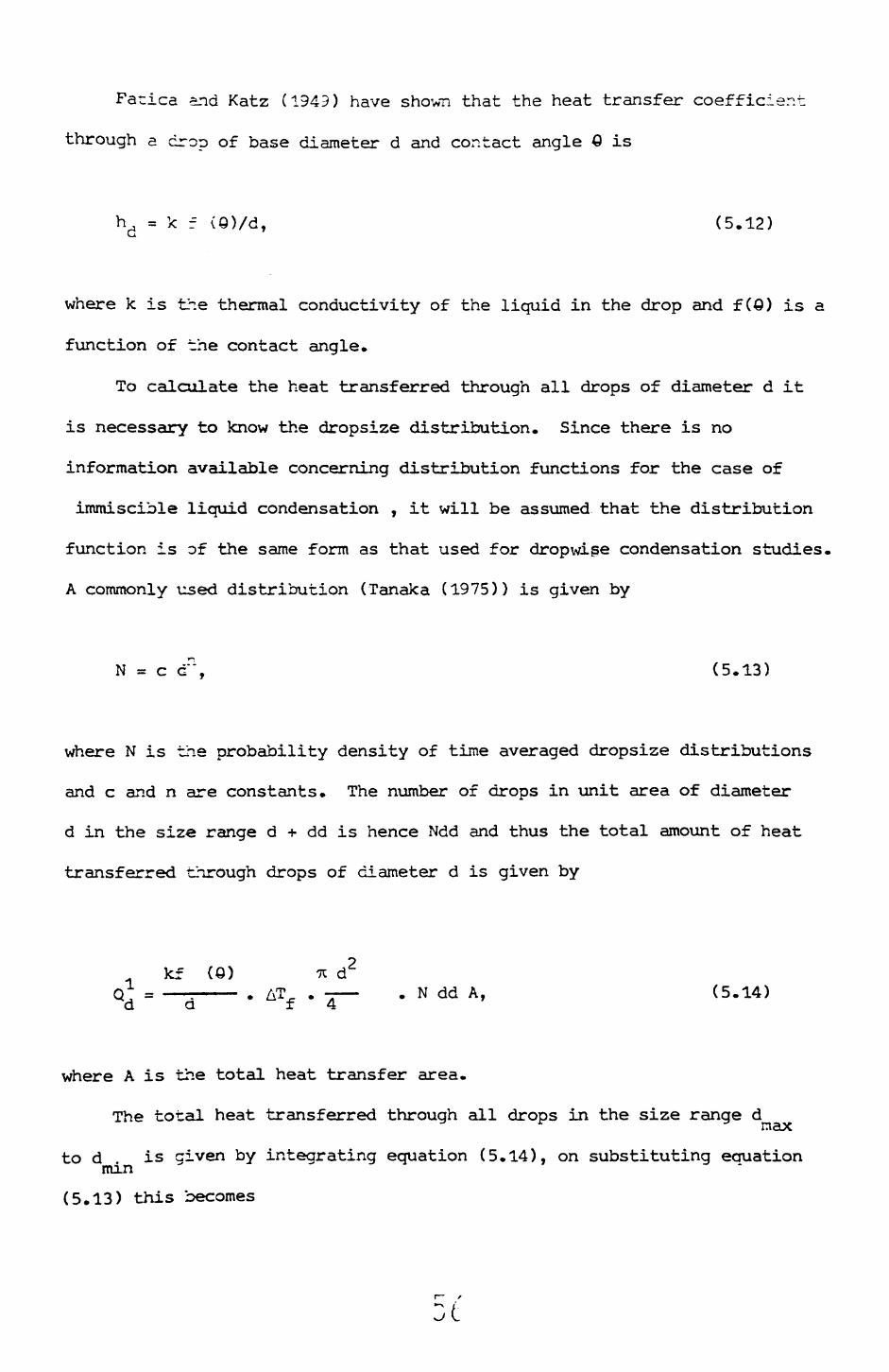
Fatica and Katz (1949) have shown that the heat transfer coefficient
through a drop of base diameter d and contact angle Q is
hd = k f (0)/d, (5.12)
where k is the thermal conductivity of the liquid in the drop and f(0) is a
function of the contact angle.
To calculate the heat transferred through all drops of diameter d it
is necessary to know the dropsize distribution. Since there is no
information available concerning distribution functions for the case of
immiscible liquid condensation , it will be assumed that the distribution
function is of the same form as that used for dropwige condensation studies.
A commonly used distribution (Tanaka (1975)) is given by
N = c cT, (5.13)
where N is the probability density of time averaged dropsize distributions
and c and n are constants. The number of drops in unit area of diameter
d in the size range d •»• dd is hence Ndd and thus the total amount of heat
transferred through drops of diameter d is given by
kf (0) n d2. AT . - —— . N dd A, (5.14) ±4
where A is the total heat transfer area.
The total heat transferred through all drops in the size range dmax
to d is civen by integrating equation (5.14), on substituting equation mm
(5.13) this becomes
t

max-k f (G)
dd. (5.15), d . 4' min
The total heat transferred through the wall is
(5.16)
where Q = h A T A and CL, is the heat transferred through the film i.e,
h AlVJ^.,. Combining 5.15 and 5.16 gives
h ATf =max
d . mm
Equation (5.17) can be written
rd
h =
maxdn+1 dd + (1-a) (5.18)
d .min
where a is the fractional area occupied by the drops. From equation (5.13)
it is apparent that,
max
dd (5.19)
' d . mm
Integrating equation (5.13) and (5.19) and combining gives
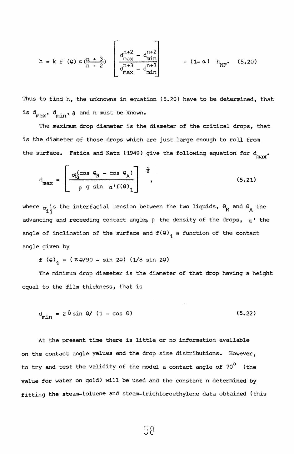
h = k f a(n,n+2 d — max,n+3 d — max
n+2 minn+3min
+ (1- a ) h.NF
(5.20)
Thus to find h, the unknowns in equation (5.20) have to be determined, that
is d , d . , Q and n. must be known, max mm
The maximum drop diameter is the diameter of the critical drops, that
is the diameter of those drops which are just large enough to roll from
the surface. Fatica and Katz (1949) give the following equation for dmax
max
- cos Q )
p g sin a(5.21)
where g- is the interfacial tension between the two liquids, 0 and Q the ij K A
advancing and receeding contact angles, p the density of the drops, a * the
angle of inclination of the surface and f (QK a function of the contact
angle given by
f («) a = (5CS/90 - sin 2Q) (1/8 sin 20)
The minimum drop diameter is the diameter of that drop having a height
equal to the film thickness, that is
d . =2 6 sin O/ (1 - cos £)min (5.22)
At the present time there is little or no information available
on the contact angle values and the drop size distributions. However,
to try and test the validity of the model a contact angle of 70 (the
value for water on gold) will be used and the constant n determined by
fitting the steam-toluene and steam-trichloroethylene data obtained (this
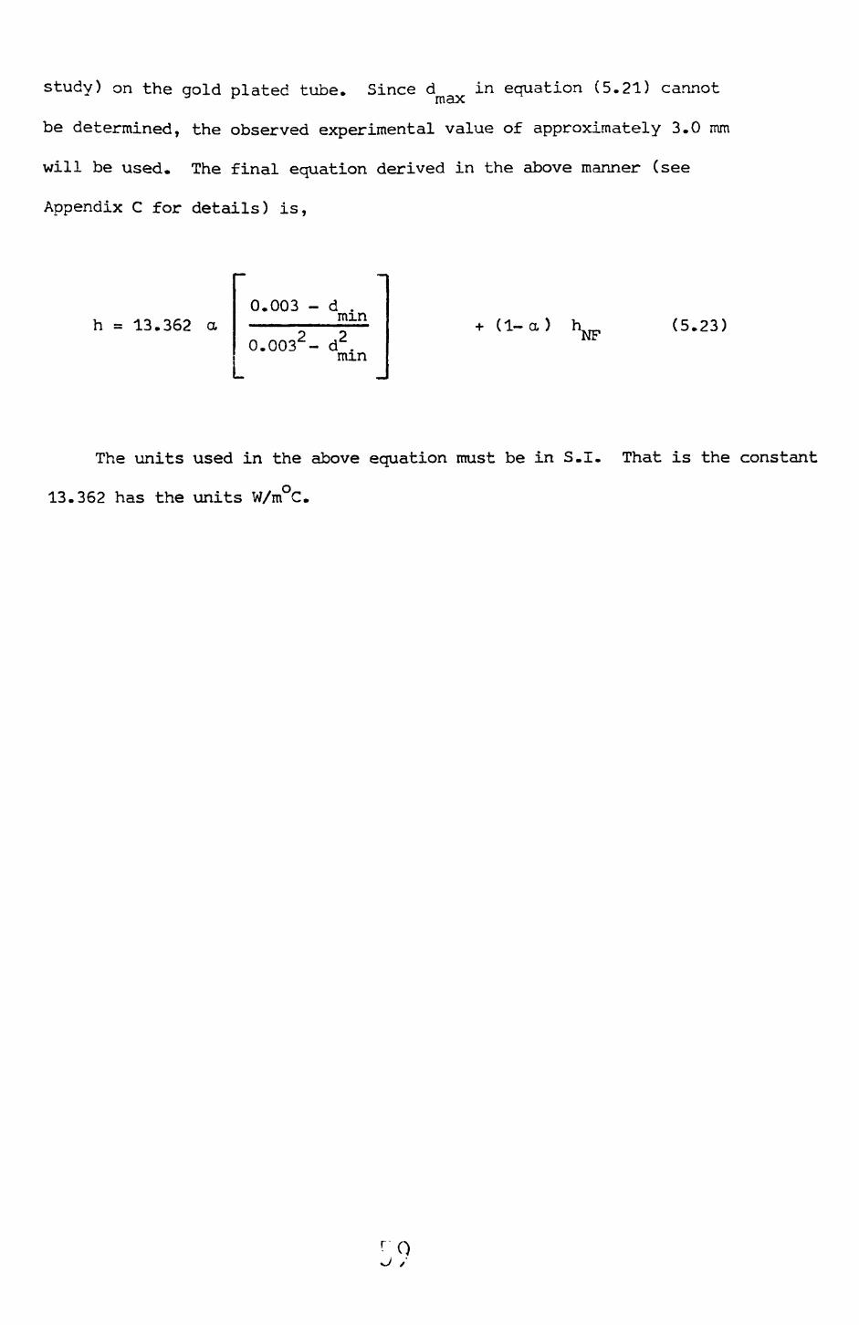
study) on the gold plated tube. Since d in equation (5.21) cannotmax
be determined, the observed experimental value of approximately 3.0 mm
will be used. The final equation derived in the above manner (see
Appendix C for details) is,
h = 13.362 a0.003 - d ._______nan
0.0032 - d2 . mm
+ (1-a) h.NF (5.23)
The units used in the above equation must be in S.I. That is the constant
13.362 has the units W/mC.
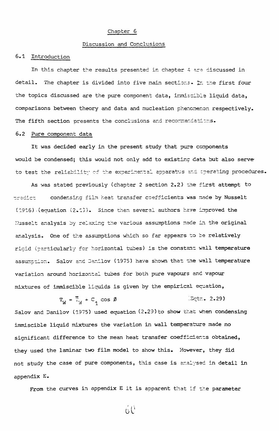
Chapter 6
Discussion and Conclusions
6.1 Introduction
In this chapter the results presented in chapter 4 ^re discussed in
detail. The chapter is divided into five nain sections. ST. the first four
the topics discussed are the pure component data, insnisclbla liquid data,
comparisons between theory and data and nucleation phenomenon respectively.
The fifth section presents the conclusions and recorrrner.doti-r.s.
6.2 Pure component data
It was decided early in the present study that pure components
would be condensed; this would not only add to existing data but also serve-
to test the reliability of the experimental apparatus sr.d :perating procedures,
As was stated previously (chapter 2 section 2.2) The first attempt to
predict condensing film neat transfer coefficients vas m,=ce by Nusselt
(1916) .(equation (2.1)5. Since then several authors have improved the
Lusseit analysis by relaxing the various assumptions m=ce in the original
analysis. One of the assumptions which so far appears to be relatively
rigid (particularly for horizontal tubes) is the const=nr vail temperature
assumption. Salov and 3arJ.lov (1975) have shown that the wall temperature
variation around horizontal tubes for both pure vapours and vapour
mixtures of immiscible liquids is given by the empirics! equation,
TT . = T. f + C cos 0 ".Ectr.. 2.29) V* // 1
Salov and Danilov (1975) used equation (2.29) to show that when condensing
immiscible liquid mixtures the variation in wall temperature made no
significant difference to the mean heat transfer coefficients obtained,
they used the laminar two film model to show this. However, they did
not study the case of pure components, this case is analysed in detail in
appendix E.
From the curves in appendix E it is apparent that if ir.e parameter

W is sufficiently large the variation in heat trar.£f~r c~efricient from
the isothermal case is quite large, a 9% increase ir. l~cal coefficient
occuring at the top of tube with o:^0.3. However, the rear, coefficient
is only 5% larger with values of o> ~ 0.3. The values :f _ :f practical
interest are usually less than 0.3 and hence the increase ir. mean
coefficient will not be greater than 5.0%.
It is apparent from the above discussion and chapiar 2 section
2.2 that Nusselts equation should be adequate for predicting the pure
component data.
The pure component data obtained in this study are compared with
the Labuntsov (1957) form of the Nusselt equation i.e.,
h_ = 0_ h. r (Eqtn. 2.~' Li L N
the crly correction taker, into account in deriving ecuc-ion (2.7)
being the variation ir. physical properties across the cor.der.sate film.
The comparison berveen equation (2.7) and the s-e=m da~a is shown
in figure 6.1; as can r.e seen the agreement is excelLer-. Figure 6.2 shows
the comparison for the toluene data, here the predictions are lower than
the data, the maximum deviation occuring at low filnt tesrpersture differences,
The tricnloroethylene ca~a is compared against equatior C2.~) in
figure 6.3, the agreement is again good, however, the predictions at film
temperature differences above about 7.0 C are high by vp to 20%.
It can be seen from figures 6.1, 6.2 and 6.3 that ihe present data
agree with Nusselts equation to within 20.0% for all ^hree components.
Thus Nusselts analysis is adequate for predicting condensation heat transfer
coefficients for the above fluids, es would be expecnec (see chapter 2
section 2.2).
The above comparisons thus show that the method of operating the
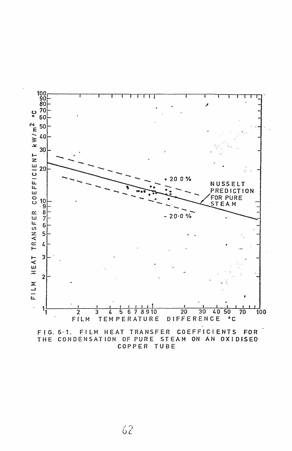
1009080
o 70 0 60" 50
LU
CO
30
ou. u_LU
gio9
ir 8765
i- 3LU"*" 2
1——T TT
+ 200 %NUSSELT PREDICTION FOR PURE STEAM
- 20-0 %
j_ » t i . i t JL t f f r f .»2 3 4567 8910
FILM TEMPER AT UR-E20 30 40 50 70 100
D tFFEREN CE °C
FIG. 6-1. FILM HEAT TRANSFER COEFFICIENTS FOR THE CONDENSATION OF PURE STEAM ON AN OXIDISED
COPPER TUBE
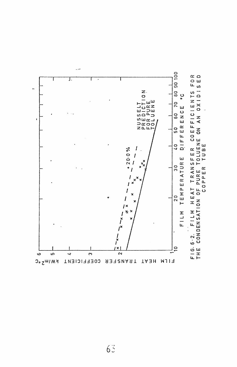
O o <N
2T.
Ul
O UJ o
o o: LU u. CO 2
< cc
h- UJ X 2: _J u.
+ 20
-0 %
XN
US
SE
LT
P
RE
DIC
TIO
N
FOR
P
UR
E
TO
LU
EN
E II
I10
FIL
M20
30
T
EM
PE
RA
TU
R E
40
50
60
70
80
90 1
00
DIF
FE
RE
NC
E
°C
FIG
. 6
-2.
FIL
M
HE
AT
T
RA
NS
FE
R
CO
EF
FIC
IEN
TS
F
OR
T
HE
C
ON
DE
NS
AT
ION
O
F P
UR
E
TO
LU
EN
E
ON
AN
O
XID
ISE
DC
OP
PE
R
TU
BE

LU
O u_
u_ LU
O
O cro o
to z < cc LU
1C
' LL
10 9 8 7 6
20-0
%
xX
X
-20-
0 %
I
XX 1.
NU
SS
ELT
P
RE
DIC
TIO
N
- F
OR
P
UR
E'TR
ICHL
OROE
THYL
ENE
_L
FIL
M5
6 7
8 9
10
T E
M P
E R
A T
U U
E20
30
40
50
60
70
809
0100
D
IFF
ER
EN
CE
°C
G.
6 O
F3.
F
ILM
H
EA
T
TR
AN
SF
ER
C
OE
FF
ICIE
NT
S
FOR
T
HE
C
ON
DE
NS
AT
ION
P
UR
E
TR
ICH
LO
RO
ET
HY
LE
NE
O
N A
N
OX
IDIS
ED
C
OP
PE
R
TU
BE

experimental apparatus, particularly the r.ethod of purging lr.czr.densable
gases, was satisfactory. That is no major deviations frcrc "<e .Vusselt
predictions exist, as would have been expected if ir.ccr.der. ==ble gases
had been present.
6.3 Immiscible liquid data
6.3.1 Effect of film temperature difference
From the literature survey (chapter 2) the
effect of film temperature difference on film heat transfer coefficients
is not certain. The data obtained in this study however,, show =-i
unmistakeable trend, that is as the temperature difference increases the
heat transfer coefficient decreases. Figure 6.4 shows that -his trend occurs
for all combinations of mixtures and surfaces used.
6.3.2 Effect of the tube surface
It is apparent from the results (chap-er 4) that: -he flow regimes
on the oxidised cooper and gold plated tubes are different. On uhe oxidised
copper surface the water-toluene and water-trichloroethylene mircures flow
from the rube in essentially the same manner, that is in rivulets flowing
side by side (channelling flow). This mechanism is very similar to the
channelling mechanise postulated by Hazelton and Baker (1944^.
The flow mechanism for the water-trichloroethylene mixture on the
gold surface was of the standing drop type previously described by
Bemhardt et al (1370) for the condensation of various organic-szeam
mixtures on a vertical gold plated surface. Here the water forned irregular
shaped standing drops in the flowing organic film. These crops rolling
from the surface after reaching a certain critical size. It was also
observed (from cine films) that there were many tiny water droplet;;
flowing with the organic film* Whether they are in or on the surface of the
film is not known.
' OJ
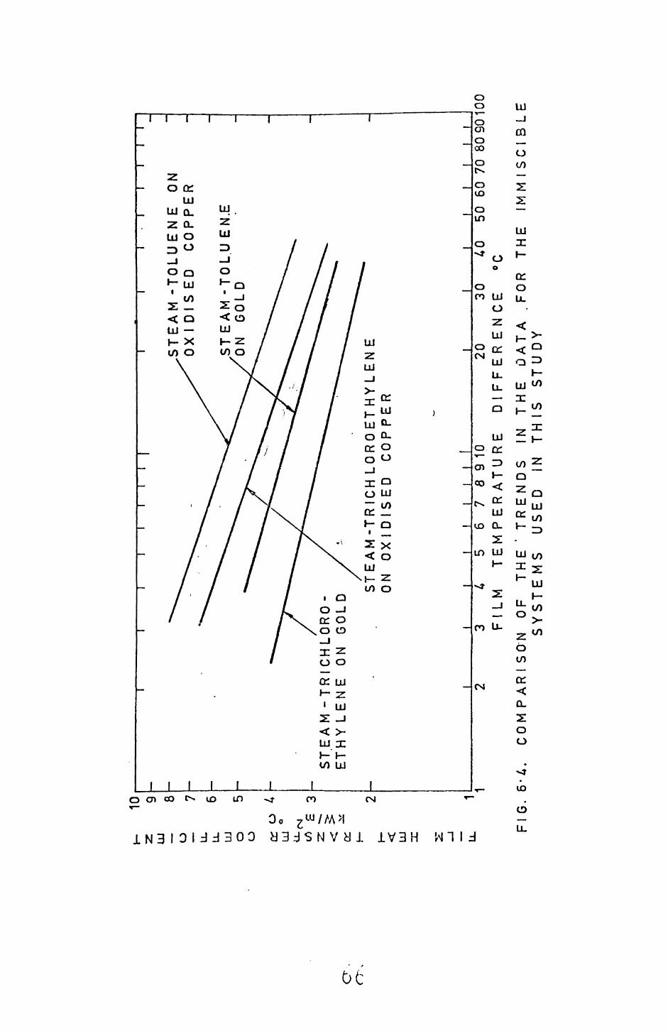
H-
Z
UJ O u.
u_ UJ o
o or LLJ
u.,
CE UJ n:
10 9 8 7 6 5 4
IIII
I I
I l
ST
EA
M -
TO
LU
EN
E
ON
X
I D
IS E
D
CO
PP
ER
M -
TO
LU
EN
.E
ST
EA
M -
TR
ICH
I E
TH
Y L
EN
E
ON
G
OL
ST E
AM
-T
RIC
H L
OR
OE
TH
YL
EN
E
ON
0X1
DIS
ED
C
OP
PE
R
I I
I I
I3
4 5
678
91
0
FlL
M
TE
MP
ER
AT
UR
E20
30
D
IFF
ER
EN
CE
_LI
I l
50
60 7
0 80
SO
100
Fl
G.
6-A
. C
OM
PA
RS
ON
O
F T
HE
S
YS
TE
MS
TR
EN
DS
U
SE
D
ININ
T
HE
D
AT
A
TH
IS
S
TU
DY
FOR
T
HE
IM
MIS
CIB
LE
The flow mechanise for the water-toluene mixtures on the gold surface
was similar to that described for the water-trichloroeihylene mixtures,
In this case however, there were far fewer standing water drops and many
more tiny water drops fl swing on or in the orcanic filr.. Also when the
large drops drained fron the surface they formed rivulets which persisted
for considerable periods of time, whereas for the water-trichloroethylene
case, when the drops drained they left only a trail cf smaller drops in
their wake.
The change in mechanisa when condensing on oxidised copper or gold
plated surfaces could be caused by a change in wetting properties.
For instance pure steam condensing on a clean oxidised copper surface
will spread over the surf ace (i.e. the contact angle is zero)), whereas
pure water on a gold surface forms crops with a finite contact angle
(approximately 70 ).
In the condensation case, on the oxidis_*d copper surface, both
liquids spread over the surface and in competing for the surface form
adjacent films. Further vapour condenses on these filrs, the organic
vapour on the organic fijja and the steam on the water film.
For the gold surracs the vapour initially condenses to form an
organic film (organics spread on gold) and standing water drops. It
would then seem that further water vapour can only condense on those
water drons which protrude through the organic film* Eventually these
drops would become large enough to roll from the surface under the action
of gravity. When the crops roll they sweep a track through the organic
film and other drops Ln their path, a track of small drops being left
in the drop wake for the steam—trichloroethylene case and a small rivulet
of water in the s team-tt luer.e case.
In the steam-toluene case the water rivulet ever.tuilly drains and the
organic film flows in over the surface, small water cjrcps being left
' ~7
0 I
as "islands" in the organic film.
For the steam-trichloroethylene case it may be speculated that the
following processes occur simultaneously:
1. The drops in the trail grow by condensation
2. The existing organic film spreads over the bare surface
3. Steam and organic vapour condense on the bare area, the organic
forming a film and the water drops.
Thus again we have an organic film plus standing water drops. The
above processes continue indefinitely.
Although the above interpretations explain the major features of the
observed mechanisms,there are still several unresolved questions regarding
the origin of the small organic droplets and the origin of the water
droplets.
Bemhardt et al (197C) speculated that the small organic drops (present
in or on the water fii~s =r.c crops) were nucleating or. rnicroscopic dust
particles on the surface of the water, also the mcving water drops could
have the same origin.
A further possibili-y is that the organic is condensing directly
onto the water drops. If this were the case it is possible that a nucleation
barrier exists to the condensation of the organic on the water. Also any
water condensing directly onto the organic film might also have to overcome
a nucleation barrier. A more detailed discussion on nucleation phenomenon
is given in section 6*5»
Another mechanism by which droplets can be produced in the respective
films and drops is as follows. Although it is often stated that the
organic-water mixtureiused in immiscible condensation studies are totally
immiscible this is rarely the case. Figures 6.5 and 6.6 show the solubility
curves for water-toluene and water-trichloroethylene mixtures.
68
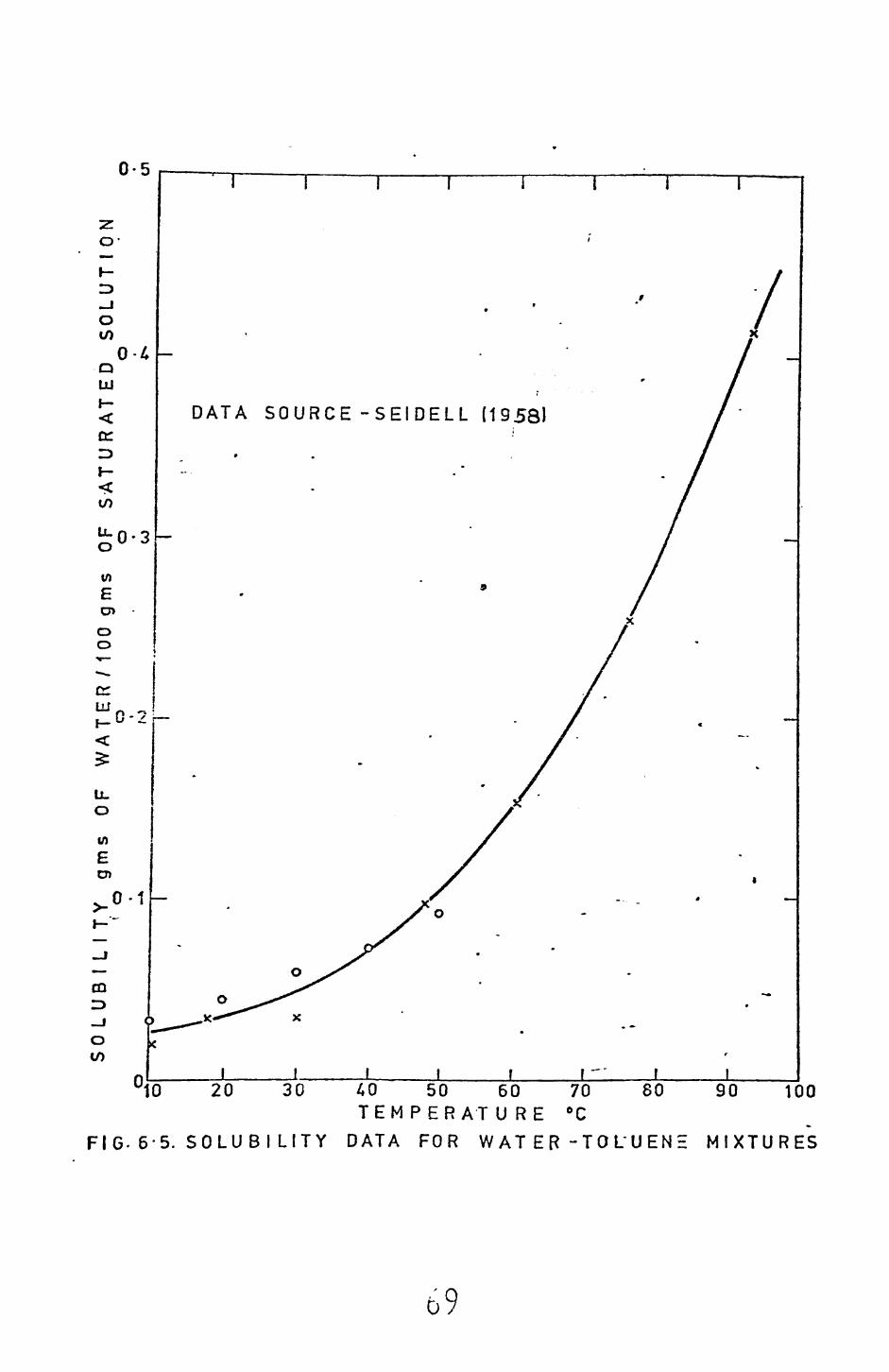
0-5
o-
I-:D _J o
Q UJI- <orIDH-
to
0-3
DATA SOURCE -SEIDELL (1958)
'10 20 30
FIG. 6-5. SOLUBI LITY
70 °C
8040 50 60 TEMPER ATURE
DATA FOR WATER -TOLUEN
90 100
MIXTURES
b

0-09DATA SOURCE KIRK &OTHMER 11964)
0
UJzLU
I- UJoDC O_l Xoo-u-
0-13 OLlJ
10 60 7020 30 40 50 TEM PERAT URE °C
FIG. 6-6. SOLUBILITY DATA FOR WAT E R - TRICHLOROETHYLENE MIXTURES
, '0-12
0-11 -CO
0-10
70
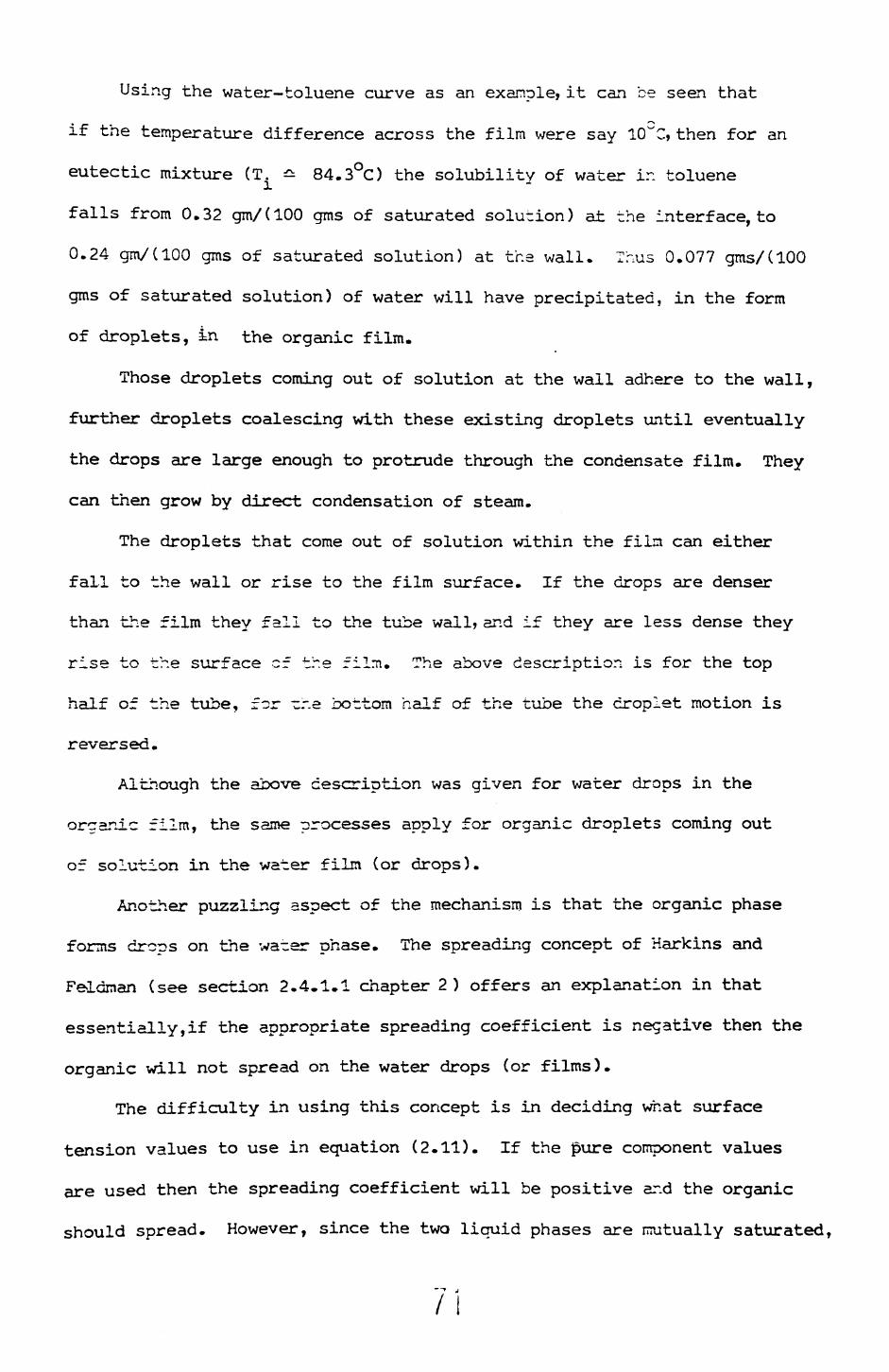
Using the water-toluene curve as an example, it can be seen that
if the temperature difference across the film were say ICTC, then for an
eutectic mixture (T^, === 84.3°C) the solubility of water ir. toluene
falls from 0.32 gm/(100 gms of saturated solution) at the interface, to
0.24 gin/(100 gms of saturated solution) at the wall. Thus 0.077 gms/(100
gms of saturated solution) of water will have precipitated, in the form
of droplets, in the organic film.
Those droplets coming out of solution at the wall adhere to the wall,
further droplets coalescing with these existing droplets until eventually
the drops are large enough to protrude through the condensate film. They
can then grow by direct condensation of steam.
The droplets that come out of solution within the film can either
fall to the wall or rise to the film surface. If the drops are denser
than the film they fall to the tube wall, and if they are less dense they
rise to the surface of tr.e film. The above description is for the top
half of the tube, for cr.e bottom half of the tube the droplet motion is
reversed.
Although the above description was given for water drops in the
organic film, the same processes apply for organic droplets coming out
of solution in the water film (or drops).
Another puzzling aspect of the mechanism is that the organic phase
forms drops on the water phase. The spreading concept of Harkins and
Feldman (see section 2.4.1.1 chapter 2) offers an explanation in that
essentially,if the appropriate spreading coefficient is negative then the
organic will not spread on the water drops (or films).
The difficulty in using this concept is in deciding what surface
tension values to use in equation (2.11). If the pure component values
are used then the spreading coefficient will be positive ar.d the organic
should spread. However, since the two liquid phases are rmatually saturated,
/I
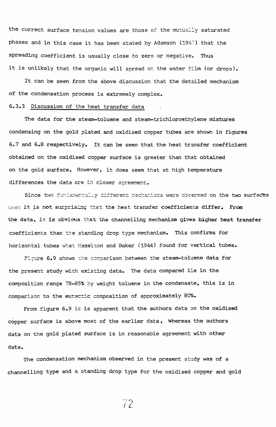
the correct surface tension values are those of the mutually saturated
phases and in this case it has been stated by Adamson (1957) that the
spreading coefficient is usually close to zero or negative. Thus
it is unlikely that the organic will spread or. the water film (or drops).
It can be seen from the above discussion that the detailed mechanism
of the condensation process is extremely complex.
6.3.3 Discussion of the heat transfer data
The data for the steam-toluene and steam-trichloroethylene mixtures
condensing on the gold plated and oxidised copper tubes are shown in figures
6.7 and 6.8 respectively. It can be seen that the heat transfer coefficient
obtained on the oxidised copper surface is greater than that obtained
on the gold surface. However, it does seem that at high temperature
differences the data are in closer agreement.
Since two fur.daner.-al_y different rr.echar.isms were observed on the two surfaces
usec it is not surprising that the heat transfer coefficients differ. From
the data, it is obvious that the channelling mechanism gives higher heat transfer
coefficients than the standing drop type mechanism. This confirms for
horizontal tubes what Hazelton and Baker (1944) found for vertical tubes.
Fig-ure 6.9 shows -he comparison between the steam-toluene data for
the present study wirh existing data. The data compared lie in the
composition range 73-85% by weight toluene in the condensate, this is in
comparison to the eunectic composition of approximately 80%.
From figure 6.9 it is apparent that the authors data on the oxidised
copper surface is above most of the earlier data > whereas the authors
data on the gold plated surface is in reasonable agreement with other
data.
The condensation mechanism observed in the present study was of a
channelling type and a standing drop type for the oxidised copper and gold

z LJ
O U.
LL UJ o
o o: UJ
LJL cc H-
UJ u_
10 9 8 7 6 4 3
• F
I G
. 6
-7
XX
V
xvX
X
• x
o o
x O
XID
ISE
D
CO
PP
ER
T
UB
E
oG
OLD
P
LA
TE
D
TU
BE
I I
I
x x
xxx
0%
0°
II
2 3
4 5
6 7
8 9
10
20
30
40
50
60
70 8
0901
00
FIL
M
TE
MP
ER
AT
UR
E
DIF
FE
RE
NC
E
°Ck
CO
MP
AR
ISO
N
OF
TH
E
ST
EA
M -
T0LU
EN
E
DA
TA
F
RO
M
TH
IS
ST
UD
Y

H-
2 UJ O u_ U. UJ o o cc UJ Li_ to 21 2 *"" h- UJ DC ^ U,
1 U 9 8 7 6 5 4
0 o E 3
|
2 . 1
IT
T
I -T
I'll]
I I
I I
I I
I I
—
, ,
—
—
• —
v
N
X-
f
-
X
X '
_
XX
i
t
\X
"" o
>u
x "^
9Co
° °
o x
X X
• "o
°
' x
x
° °o
°
° °
x O
XID
ISE
D
CO
PP
ER
T
UB
E
.oG
OLD
PLA
TE
DT
UB
E
1 1
1 I
I I
I I
1 I
I i
i i
i |
i2
3 4
5 6
7 8
91
0
20
30
40
50
60
70
80
90
10
0F
ILM
T
EM
PE
RA
TU
RE
D
IFF
ER
EN
CE
°C
FIG
. 6
• 8 .
CO
MP
AR
ISO
N
OF
THE
S
TE
AM
- T
RIC
HL
0R
0E
TH
YL
EN
EF
RO
M
TH
IS
ST
UD
YD
AT
A

LU
O iZ
U.
LU o
o
10 9 8 7 6 5
0:0
4LU
o
z^3
UJ X
_1—
XX
x
*^>
*><
^3
O
OA
D
• ...
* .1
,
o o
o0
0
• ••
• •
x T
HIS
S
TU
DY
O
XID
ISE
D
CO
PP
ER
T
UB
E
(25
• 40
m
m
O.D
.JO
TH
IS
ST
UD
Y
GO
LD
P
LA
TE
D
T U
D E
(25-4
0m
m
0. D
.)A
BA
KE
R
& M
UE
LLE
R
(193
7)
OX
lDIS
tlD
C
OP
PE
R
TU
BE
|3
3-3
5m
m
O.D
.)O
S
YK
ES
(1
96
8)
OX
IDIS
ED
C
OP
PE
R
TU
BE
(3
4-9
3 m
m
O.D
.J•
ST
EP
AN
EK
&
ST
AN
DA
RT
(1
958
) -
(9-9
8m
m
O.D
.)
1
F I
G.
6-9
. •C
OM
PO
SIT
ION
L 8I
j_I
150
50
70
8090
100
2 3
4 5
6 7
8 9
10
20
30F
ILM
T
EM
PE
RA
TU
RE
D
IFF
ER
EN
CE
°C
CO
MP
AR
-IS
ON
O
F E
XIS
TIN
G
ST E
A M
-
T 0
L U
E N
E D
AT
A
IN
TH
E
RA
NG
E
78
-85%
BY
W
EIG
HT
T
OLU
EN
E
IN
TH
E
CO
ND
EN
SA
TE
plated tubes respectively. The mechanism described by Baker and Mueller
(1937) appears to be of the standing drop type, whereas that by Sykes
(1968) a mixture of the channelling and standing drop types. Thus it
would be expected tnat Baker and Mueller and Syke's data should either
agree with the gold plated data or lie between the gold plated and
oxidised copper tube data of this study. And indeed for the majority of
the data this is the case (see Figure 6.9).
1^ is interesting to note, however, that the surfaces used by the
other two sets of workers were reported as being oxidised copper. Thus
it seems that the mechanism obtained on apparently similar tubes can be
different. In the vertical plate study by the author (described in
appendix F) it was observed that a mixed channelling-standing drop
mechanism was obtained. However, in this particular study on the vertical
plate no precautions were taken to ensure that filmwise condensation of
steam was obtained on the copoer surface before use.
From the above discussion it would seem that the properties of
an oxidised copper surface vary with time (this has previously been
suggested by Ponter ar.d Diah (1974)). Initially a standing drop type
mechanism being obtained, rhis apparently transforming to a channelling
type flow after some unknown period of time. A way of confirming the
above suggestions would be to continuously condense a given vapour
mixture or. an initially polished copper tube) any variation of mechanism,
with time, could then be observed.
An interesting feature of figure 6.9 is the position of the Stepanek
and Standart (1958) data. Because this data is mucn lower than other data
sets, several authors (Bernhardt et al (1970), Ponter and Diah (1974))
have suggested that the discrepancy is caused by the presence of incond
ensable gases. However, Standart (1973) has stated that a vent line had
been included in the apparatus and that incondensable gases had been purged
76
from the system. A possible reason for this data set being so far below
the others is due to the effect of tube ci^-eter. As was started in chapter
2 several workers have observed that for snail diameter tubes the heat
transfer coefficient, increases as the tube diameter increases, and since
th-:? -ube diameter of Scepanek and Star.car- (1953) was crdy 9.33 nin in
comparison to the more common diameters of between 25.40 and 34.93 mm
it is possible that this effect might explain the discrepancy.
Figure 6.10 shows the comparison between the authors steam-trichloro-
ethylene data and Baker and Muellers (1937) data. As can be seen the
agreement is not good, the Baker and Muller (1937) data being considerably
higher at high temperature differences than this study. The reasons for
the discrepancy is not known, but presumably surface properties are of
importance.
6.4 Comparison between theory and data
The comparison between the authors channelling data and the channelling
model (equation (5,")} is shown in figures 5.11 and 6.12. The theoretical
line was calculated for -he eutectic rrdxture in each case. From the
figures it can be seen that the model ur.cerpredicts quite considerably.
1r. order to nrecicrt the cats satisfactorily an enhancement factor
of 1.5 is introduced. Thus ecuation (5.7) becomes
h = 1.5 (h^/Cl-Y) -r h-^Y/(l+Y)) (6.1)
The agreement between ecuation (6.1) and the data (see figures 6.11
and 6.12) is to within + 20.0%.
"7 -'
/ /
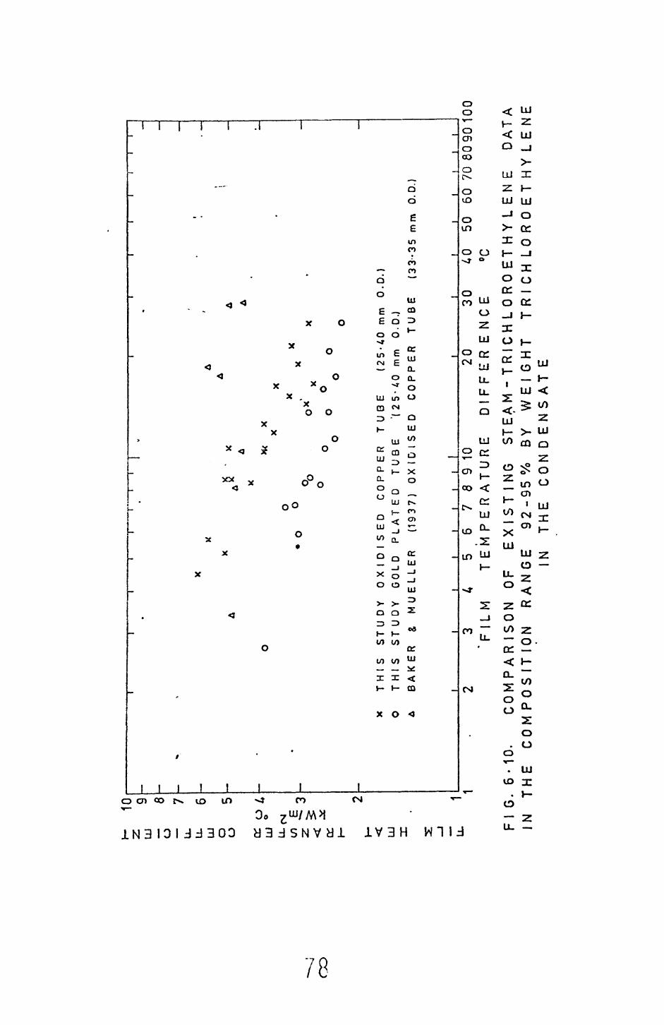
CO
UJ o u_
u. UJ o
o a: LU u.
10 9 8 7 6
o: h- UJ X
1 1
X AA A
O o°c
o
x T
HIS
S
TU
DY
O
XID
ISE
D
CO
PP
ER
T
UB
E
(25-A
Om
m
0.0
.)O
TH
IS
ST
UD
Y
GO
LD
PLA
TE
D
TU
BE
'(2
5-4
0
mm
O
.D.)
A B
AK
ER
&
MU
EL
LE
R
(1937)
OX
IDIS
ED
C
OP
PE
R
TU
BE
{3
3-3
5
mrn
O
.D.
I3 FIL
M40
50
60
70
809
0 10
0°C
5 6
7 8
9 10
20
30
T
EM
PE
RA
TU
RE
D
IFF
ER
EN
CE
FIG
. 6
-10.
CO
MP
AR
ISO
N
OF
EX
IST
ING
S
TE
A M
- T
R I
C H
L 0
R 0
ET
H Y
L E
N E
DA
TA
IN
T
HE
C
OM
PO
SIT
ION
R
AN
GE
9
2-9
5%
B
Y
WE
IGH
T
TR
ICH
LO
RO
ET
HY
LE
NE
IN
TH
E
CO
N D
EN
S A
T E

Fl
G.
6-11
. FO
R
20
30
DIF
FE
RE
NC
E
°C,
2 3
£56
78
9 1
0 F
ILM
T
EM
PE
RA
TU
RE
CO
MP
AR
ISO
N
BE
TW
EE
N
TH
E
CH
AN
NE
LL
ING
T
HE
C
ON
DE
NS
AT
ION
O
F S
TE
AM
- T
0L
UE
NE
OX
IDIS
ED
C
OP
P E
R
TU
BE
50
60
70 8
09
01
00
MO
DE
L
AN
D
T H
E
DA
TA
M
IXT
UR
ES
O
N
AN
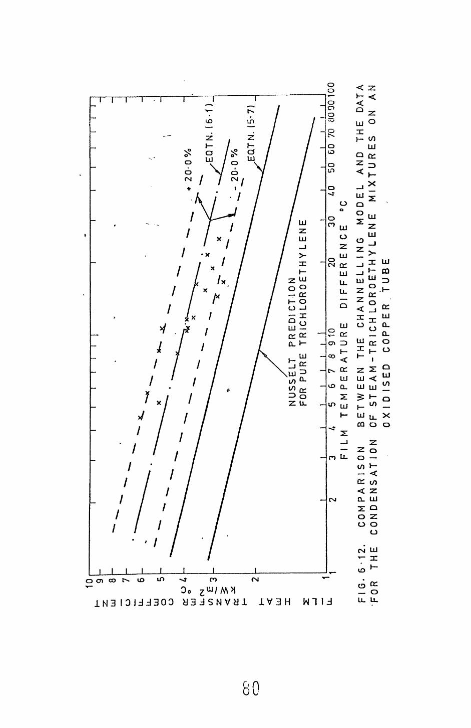
CO
C
D
U. FIG
. 6
-12
. 'F
OR
T
HE
3 FA
LM5
678
91
0
TE
MP
ER
AT
UR
E20
30
AO
D
IFF
ER
EN
CE
°C
50
GO
70
0090
100
CO
M P
AR
IS
ON
C
ON
DE
NS
AT
IO
NB
ET
WE
EN
TH
E
CH
AN
NE
LL
ING
M
OD
EL
AN
D
TH
E
DA
TA
O
F S
TE
AM
-TR
1C
H L
OR
OE
TH
YL
EN
E
MIX
TU
RE
S
ON
A
N
OX
IDIS
ED
C
OP
PE
R
TU
B E

T>The discrepancy between the original theory (£~~-icr. (5.7)) and
the data mav be due to the effects of the water drr-s protruding through
the organic film and/or the small organic drops in -ihe water films.
Either of these could cause disturbances in the filr.s, thus promoting
::e--:cr nixir.g and hence increased rates of haat tri:.3fer. If so, higher
transfer coefficients than those predicted by the si-pie laminar film
nodal would be expected.
It can be shown (chapter 5 section 5.2) that the Bernhardt correlation
(equation (2.18)) is a special case of equation (5.7) and that for most
organic-water mixtures the differences between the iwo equations is less
than 4_ 5.0%. It is thus apparent that equation (5.7) will fit the same
data as the Bernhardt correlation. Bernhardt et al (1972) have stated
that their correlation fits the majority of the existing data to within
an average error of _+_ 15.0%.
Since much of the earlier data has not been of a purely channelling
type it would seem that the excellent predictions -f the Bernhardt
correlation have been somewhat fortutious.
In particular if the Bernhardt correlation is -crnpared in detail
with existing steam-toluene data it can be seen (figure 6.13) that the
correlation does not predict the data to anywhere near +^ 15.0%, over-
predicting some data by factors of two or more and underpredicting a
considerable amount of data by up to 50%.
01
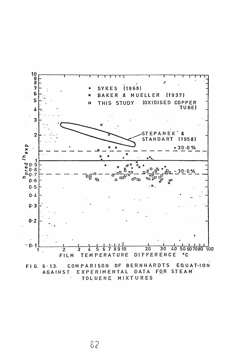
1098765
k
3
2
CLx '
:: 1
J!0-8
" 0-60-5
0-4
0-3
0-2
'
i i i i i i i i | i i i i I I I I"™ » * *
- - • SYKES (1968)-.-- x BAKER & MUELLER (1937)"•* ' o THIS STUDY {OXIDISED COPPER- ' TUBE)
mim » , -
' C^^"*"*"*^-*^^ x ;.-:..- ^""'^^^^r^^'^*^^ ^-STEPANEK'fc. •; ^^--^^^^<^ STANDART (1958)
xx""*^*"*^ •* n n °/— _ _ _ — __ _ _K _ — — —— — —— — — — —— — ~, ° — . _
x • , x - •o *<»
X
_o * !P B*'Q ^ o^aSc !io.-30-o% -
** x- •• x -
_ « . -
t
" L .
- * • i i i i i i t 1 t i t i t i i. i
° 1 1 2 3 4 5 6 7 8910 20 30 40 50607080 100FILM TEMPERATURE DIFFERENCE °C
FIG. 6-13. COMPARISON OF BERNHARDTS EQUAT-ION AGAINST EXPERIMENTAL DATA FOR STEAM'
TOLUENE MIXTURES
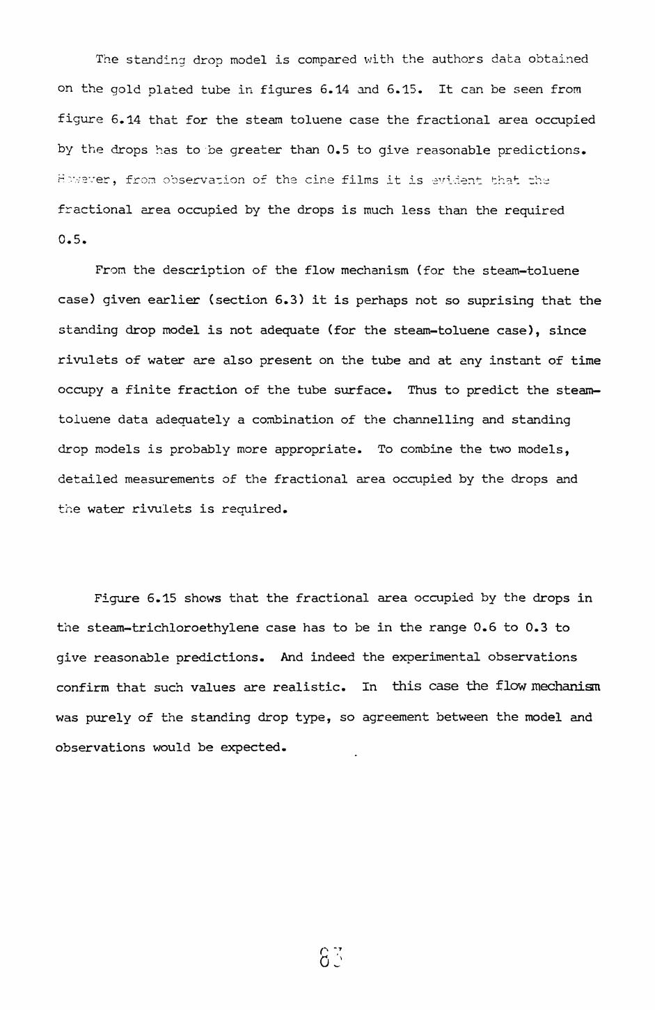
The standing drop model is compared with the authors data obtained
on the gold plated tube in figures 6.14 and 6.15. It can be seen from
figure 6.14 that for the steam toluene case the fractional area occupied
by the drops has to be greater than 0.5 to give reasonable predictions.
H y.-;2ver, from observation of the cine films it is evident that t:hvi
fractional area occupied by the drops is much less than the required
0.5.
From the description of the flow mechanism (for the steam-toluene
case) given earlier (section 6.3) it is perhaps not so suprising that the
standing drop model is not adequate (for the steam-toluene case), since
rivulets of water are also present on the tube and at any instant of time
occupy a finite fraction of the tube surface. Thus to predict the steam-
toluene data adequately a combination of the channelling and standing
drop models is probably more appropriate. To combine the tivo models,
detailed measurements of the fractional area occupied by the drops and
the water rivulets is reouired.
Figure 6.15 shows that the fractional area occupied by the drops in
the steam-trichloroethylene case has to be in the range 0.6 to 0.3 to
give reasonable predictions. And indeed the experimental observations
confirm that such values are realistic. In this case the flow mechanism
was purely of the standing drop type, so agreement between the model and
observations would be expected.
O V OJ
CO r-.
LL.
FIL
M5
6 7
8 9
10
TE
MP
ER
AT
UR
E20
30
F
FE
R E
NC
E50
60
70
80
10
0
FIG
. 6
'U.
CO
M P
AR
ISO
N
ST
E A
M -
TO
LU
EN
EB
ET
WE
EN
T
HE
S
TA
ND
ING
D
RO
P
MO
DE
L
AN
D
TH
E
DA
TA
O
BT
AIN
ED
O
N T
HE
G
OLD
P
LA
TE
D
TU
BE

CO
LU
O Lu
LU
LU
O
O LU.
10 8 7 6 5
CC h- LLl
X
T I
I I
I T
I I
I
NU
SS
ELT
P
RE
DIC
T I
ON
FO
R
PU
RE
T
RIC
HLO
RO
- E
TH
YL
EN
E
II
I I
I
of =
0-6
« =
0-3
Fl
LM5
6 7
8 9
10
TE
MP
ER
AT
UR
E20
30
D
IFF
ER
EN
CE
'
40
50
60 7
0 80
10
0
FIG
. S
TE
6-1
5.
CO
MP
AR
ISO
N
BE
TW
EE
N
TH
E
ST
AN
DIN
G
DR
OP
M
OD
EL
A
M -
TR
ICH
LO
RO
ET
HY
LE
NE
D
AT
A
OB
TA
INE
D
ON
T
HE
G
OL
DC
OP
PE
R
TU
BE
AN
D
TH
E
PLA
TE
D
Several of the details of the flow mechanism have been ignored in the stand
ing drop model such as the effect of the small organic droplets on the standing
water drops. Pres.umably these organic droos will be a
further resistance to heat transfer. Another important feature of the
mechanism which has been ignored is the effect of the continual sweeping
of the surface by the rolling drops. This would cause an
increase in the heat transfer rate, since the organic film is continually
being disturbed.
To support the standing drop model further work is needed to
determine contact angles, dropsize distributions and the dropsize range
which is effective in transferring heat to the wall. Also
some suitable combination of the channelling and standing drop model
might provide the basis for predicting any data set. A further requirement
in trying to predict heat transfer coefficients for immiscible systems is
a method of predicting the condensation mechanism for any combination
of organic-water mixtures on any specified surface.
6.5 Nucleation barriers
As was stated earlier^ the possibility exists that the organic vapour
might be condensing on the water or the steam on the organic film. If this
is the case then it is likely that a certain degree of vapour subcooling
is required before condensation can take place, that is a nucleation
barrier exists.
Consider the case of the organic vapour condensing on a water film
(or drop). The free energy required to form a drop which is part of a
spherical segment is (see appendix D),
(r») =l^a- r* 2 (2 + cos 0) (1 - cos 0) /4
For organic vapour condensing on the water phase the contact angle
is likely to be zero or near zero, thus the free energy to form a drop
is zero or small. That is there is a very small or no barrier to the
condensation of organic vapour on water.
Kcv;ev<-:?r, when water is condensing on the organic it is xir.own th^t
water will not spread on organic films, that is a finite contact angle
exists. Thus a free energy barrier will exist for this case. Unfortunately
there seems to be no data available on the value of the required contact
angles. In appendix D it can be seen from figure (D2) that for a steam-
toluene mixture the degree of subcooling required is a strong function of
contact angle. Thus with a contact angle of 30 the degree of subcooling
required is approximately 2.7 C whereas for a 60 angle the degree of
subcooling is approximately 9.2 C.
A few qualitative experiments were performed to try and test if
nucleation barriers are of importance. To do this the following procedure
was adopted. The cooling water (passing through the tube) temperature was
raised to a level high enough to give very small film temperature differ
ences ( ~1.0 C based on T -T ). The condensation mechanism was thene w
observed. If any significant barrier to the nucleation of one phase
existed a change in appearance of the condensate would be expected. In fact
it was found that for all the tests conducted the mechanisms were identical
to those described earlier (section 6.3). Thus indicating that if nuclea
tion barriers were present the vapour subcooling required to overcome the
added resistance is less than 1.0 C.
An interesting speculation is that nucleation barriers are not
important in "immiscible liquid condensation" because there are other
mechcinisms by which the steam may condense (for example the solubility
effect described earlier in section 6.3) which offer less resistance than
the nucleation path.
r- -7G/
5.6 Conclusions and RecorrLT.sr.cations
1. Nusselts equation is adequate for predicting film heat transfer
coefficients for the condensation of pure steam, t-lucne and trichloro-
ethylene.
2. The film heat transfer coefficients for the zor. ter.sation of vapours
of immiscible liquids decreases as the film temperature difference increases,
3. For binary immiscible systems two distinct fundamenta! modes of
condensation were observed, namely a channelling mode and a standing
drop mode.
4. The mode of condensation depended on the condenser surface being
used, the channelling mode being observed on an oxidised copper surface and
the standing drop mode on a cold plated surface.
5. For a given binary immiscible system the film heat transfer
coefficients for the channelling mode are greater than those for the
standing drop mode. That is the oxidised copper surface gives greater
rates of heat transfer than the gold plated surface for a given mixture.
6. The origin of the small water and organic droplets, which have
previously been attributed to nucleation effects, nay be due to solubility
phenomenon.
7. Models for predicting film heat transfer coefficients for both the
channelling and standing drop modes have been presented.
Recommendations
1. The detailed condensation mechanism requires further study. Dropsize
distributions, contact angles and detailed surface effects being of
particular importance.
2. The detailed effects of tube diameter on the condensation process
needs further study.
3. Other aspects which have so far received little or no attention
in connection with the condensation of vapours of imiscible liquids are:
r ' 0oc

(a) Vapour shear effects
(b) Condensation on tube banks
(c) Intube condensation
(d) Work on mixtures of more than two components
(e) Effects of incondensable gases
All of the above are of particular importance in industrial
applications.
p.Q 0 /
References
AKERS, W.W. and TURNER, M.M. (1962). Condensation of vapours of
immiscible liquids, A.I.Ch.E.J., No.5, pp.587-589.
ADAMSON, A.W. (1967) Physical chemistry of surfaces, John Wiley and Sons,
second edition.
ARNOLD, E. (1970). U.K. Steam tables in S.I. units, Published for the U.K.
committee on the properties of steam by Arnold Ltd. London.
BAKER, E.M. and MUELLER, A.C. (1937). Condensation of vapours on a
horizontal tube Parts I and II. Ind. Eng. Chem. 29, No.9, pp.1065-1072
and also Trans. Am. Inst. Chem. Eng. 33, pp.539-558.
BAKER, E.M. and TSAO, U. (1940). Heat transfer coefficients for
condensation of vapours of water and nonmiscible organic liquids, Ind.
Eng. Chem. 32, No.8 pp.1115-1121 and also Trans. Am. Inst. Ch. E. 36,
pp. 517-539.
BARNEA, E. and MIZRAHI, J. (1972). Heat transfer coefficient in the
condensation of a hydrocarbon-steam mixture, Trans. Inst. Ch. E. 50,
pp. 286-288.
BERNHARDT, S.H. (1970). Condensation of immiscible mixtures, Ph. D.
Thesis, Univ. of Illinois.
BERNHARDT, S.H., SHERIDAN, J.J. and WESTWATER, J.W. (1972). Condensation
of immiscible mixtures, A.I. Ch. E. Symp. Ser., Vol.68, No.118, pp.21-37.
BOYES, A.P. and PONTER, A.3. (1972). Condensation of immiscible binary
systems, Chem. Proc. Eng. Heat Transfer Survey, pp.26-30.
BROMLEY, L.A. (1952). Effect of heat capacity of condensate, Ind. Eng.
Chem. 44, pp. 2966-2969.
BUTTERWORTH, D. (1972). Personal communication.
COLLIER, J.G. (1972). Convective boiling and condensation, McGraw Hill
Book Co., pp. 301-303.
on
CHADDOCK, J.3. (1957). Filr. rcr.der.sation of vapour in a hcrizsntal tube,
•~—• Sng., 90-95, pp. 36-41.
OZ:,". K.M. (1961). An analyiir=l study of laminar film condensation:
^—~~ I - flat plates, Part II - sir.cle and multiple r.orizcr.-al tubes,
J. Heat Transf. Ser. C. 83, p;. 48-60.
CHV:;, K.R. and SEBAN, R.A. (i:-~l). Heat transfer to evaporating liquid
fii-s, J. Heat Transf. Ser. C. £3_, pp.391-396.
C:c?£R, A.H., HALL MORRISOM, I. and HENDERSON, H.E., Heat transfer of
condensing organic vapours T Ire. Eng. Chem. 34, No.l, pp.79-84.
EDWARDS, D.A., BONILLA, C.P. =nd CECHELLI, M.T. (1943). Condensation
cf water, styrene and butacrLere vapours, Ind. Eng. C:em. 40, !o.6,
pp.1105-1112.
E.-gineering Science Data Ur_it CEi.S.D.U.) (1966). Approxima-e data on the
\iscosity of some common liquids, Item No. 66024.
E.S.D.U. (1968). Thermal conaictivity of liquid halogenated aliphatic
hydrocarbons including comnnemLal refrigerants, Item No. 68024.
E.5.D.U. (1974). Thermal conractivity of liquid aromatic hydrocarbons,
I-e=n No. 74007.
E.S.D.U. (1974). Thermodynannc properties of toluene, Itera No. 74024.
FA2TCA, N. and KATZ, D.L. C1345). Dropwise condensation, Cheni. Eng.
Progress, 45, pp.661—674.
F70TI, T., UEHARA, H. and CDA. K. (1972). Filmwise condensation on a
surface with uniform heat rlizr =nd body force convection, Heat Transf.
J=p. Res. Vol.1, No.4, pp.TS—rB.
^.zi.T.ArjT, R.W. (1970). Physical properties of hydrocarbons, Vcls. 1 and
2, Gulf publishing Co.
HAZELTON, R.H. and BAKER, E.K. (1344). Condensation of vapours of
liquids, Trans. Ar- Ir.st. Ch. E. 40, pp. 1-28.
0 i
HILL, P.G., WHITING, H. and DEMETRI, E.P. (Ir53). Condensation cf
metal vapours during rapid expansion, J. Heat Transf. 83, pp. 3C3-317.
International Critical Tables (1930).
JAMIESON, D.T., TRYING, J.3. and TUDHOPE. J.S. (1974). The therr=»l
conductivity of liquids a data survey to 1972, H.M.S.O. publication.
JEFFREYS, J.O. (1936). Cornell Univ., Exp. £-., Bulletin No. 21.
KAPITZA, P.L. (1948). Wave motion in the flew of thin layers of
viscous liquid, Zh. Eksp. Theoret. Flz. 13, pp. 7-18.
KAWASKI, J., HAYAKAWA, T. AND EV JIT A, S. (1972). Condensation of
binary mixtures of vapours of immiscible liquids, Heat Transf. Jap. Res.
Vol.1, No.l, pp. 33-38.
KIRK AND OTHMER (1964). Er.cylopedia of Checa. Tech., Sec. Ed.
KIRK3RIDE, C.G. (1933). Heat transmission by condensing pure and mixed
substanced on horizontal ~--ibes, Ind, Eng. Chert. 25, No. 12, pp.1324—1330.
KOH, J.C.Y.,. SPARROW. Z.X. and HARTXETT, J-?. (1961). The two phase.
boundary layer in laminar film condensation, Int. J.H.M. Transf. _2_,
pp. 69-32.
LA3UNTSOY, D.A. (1957). Effect of temperature dependence of physical
parameters of conder.sa-e or. heat transfer In fi_m condensation of steam,
Teploenergetika, ^, pp.49—51.
XARSCHALL, E. and HICKMAN, R.S. (1973). Laminar gravity flow fiLii
condensation of binary vacour mixtures of irrriiscible liquids, J. of
Heat Transf. Ser. C. 95, pp. 1-5.
KERTE, H. (1973). Condensation heat transfer, Adv. in Heat Transf., 9_, pp.181-272,
MCADAMS, W.H. .(1954). Heat Transmission, McGraw-Hill.
MIRKOVITCH, V.V. and MISSEN, R.W. (1961). Nor. filmwise condensation of
binary vapours of miscible liquids, Can. J. Chert. Eng. 39, pp. 86-37.
MJ35ELT, V/. (1916). Surface condensation cf water vapour, Parts I and II.
Z. Ver. D. Ing. 60 No.27, pp. 541-546 and :.o. 23, pp.569-575.
92'

PATTERSON, v;.C. et al. (1937). The condensation of steam and heptane on
vertical tubes. Trans. Am. Inst. Chem. Er.g. 53, pp.216-241.
PATTON, E.L. and FSAGAN, R.A. (1941). Heat transfer coefficients for the
condensation of nixed vapours of turpentine sr.d water on a single horizontal
tube, Ind. Eng. Chem. 33, No. 10, pp. 1237-1229.
PONTER, A.B. and DIAH, I.G. (1974). Condensation of vapours of immiscible
binary liquids on orizontal copper and polytetrafluoroethylene coated
copper tubes, Warme und Stoffubertragung, 7, No.2, pp.94-106.
POOTS, G. and MILES, R.G. (1967). Effects of variable physical properties
on laminar film condensation of saturated steam on a vertical flat plate.
Int. J. H. M. Transf. 10, pp. 1677-1692.
ROHSENOW, V/.M. (1956). Heat .transfer and -einperature distribution in laminar
film condensation, Trans, A.S.M.E. 78, pp. 1545-1648.
SALOV, 7.5. and DANILGV. O.L. (1375). The condensation of binary
mixtures of the vapours of imlscible Ilcruids on non isothermal surfaces,
Int. Chert. Eng., Vol. 15, I.'o.l, pp.39—43.
SE3DELL, A. (1953). Solubilities-Inorganic and Metal Organic Compounds,
Vol.1, 4~h edition. Ar.eri~an Chem. Soc.
SPARROW, E.M. and GREGG, J.L. (1959). A boundary layer treatment of
laminar film condensation, J. Heat Transf. Ser. C. 81, pp. 13-18.
STANDART. 3. (1973). Personal communication
STEPANEK, J. and STANDART, G. (1958). Heat transfer during the condensation
of mixtures of vapours of immiscible liquids. Collection Czech. Chem.
Commun. 23, pp. 995-1011.
SYKES, J.A. (1968) Condensation heat transfer for vapours of immiscible
liquids outside horizontal copper tubes. Ph. D. Thesis. Univ. of Maryland.
SYKES, J.A. and MARCHELLO, J.M. (1970) Condensation of immiscible liquids
on horizontal tubes, Ind. Eng. Chem. Proc. Des. Dev. Vol.9, No.l, pp.63-71.
0 s

TANAKA, H. (1975). Measurement of dropsize distributions during transient
dropwise condensation, J. Heat Transf. Ser. C. Vol.97, No.3, pp. 341-346.
TIMMERMANS, J. (1950). Physics chemical constants of pure organic
compounds, Elsevier publishing Co.,
TIMMERMANS, J. (1965). Physico-chemical constants of pure organic
compounds, Vol.2, Elsevier publishing Co.
TOBIAS, M. and STOPPEL, A.E. (1954). Condensation of vapours of water
and immiscible organic liquids, Ind. Eng. Chem. 46, pp. 1450-1455.
TURNBULL, D. (1950). Kinetics.of heterogeneous nucleation, The J. of
Chem. Phys. Vol.18, No.2, pp. 198-203.
van der WALT, J. and KROGER, D.G. (1971) Heat transfer during film
condensation of saturated and superheated freon-12, Prog. H.M. Transf.
Vol.6, pp.75-98.
var. ES, J.?. and HEZHTJZ5. P.M. (1952). The condensation of vapour
of a binary mixture. Hri~. Chen. Eng. Vol. 7, No. 8, pp. 580-586.
VO3KRE5EN5KIY, K.D. vl94S). Calculation of heat transfer in film condensation
allowing for the temperature dependence of the physical properties of the
cor.denss-e, USSR, Acac. Sci. OTK. (As reported by Poots and Miles (1967)).
YUSOFOVA, V.D. and NEIKDVCHT, N.N. (1970). An investigation of the process
of condensation of gasoline vapour in the presence of water vapour,
Int. Chert. Eng. 10, No.3, pp.422
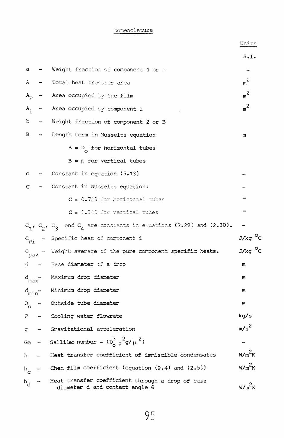
nomenclature
Units
S.I.
a - Weight fractior. of component 1 or A -*~\
A - Total heat transfer area m^
2A^ - Area occupied by the film m
2A. - Area occupied by component i . m
b - Weight fraction of component 2 or 3
B - Length term in Nusselts equation m
B = D for horizontal tubes o
B = L for vertical tubes
c - Constant in equation (5.13) -
C - Constant in Nussel~s equation: -
C = C.723 for horizontal tubes "~
C= C.r42 fzr ver-ic=l tubes
C^, C,,, C and C^ are rcr.s-snts in equations (2.29: and (2.30).
C_. - Soecific heat cf corrocnent i J/kg C
C - //eight average ~f -he pure component specific heats. J/kg C
c - 3ase diameter ~f =. ircp m
d - Maximum drop diameter m max
d . - Minimum droo diEiseter m nan
D - Outside tube diameter m o
F - Cooling water flowrate kg/s
2g - Gravitational acceleration m/s
^2 2Ga - Gallileo number - (D~ p g/ji )
h - Heat transfer coefficient of immiscible concensates W/m K
h - Chen film coefficient (equation (2.4) and (2.5*) W/m K c
h - Heat transfer coefficient through a drop of basediameter d and contact angle Q W/m K
or

- Heat transfer coefficient for euie-ctic mixtures.
- Heat transfer coefficient defined by equation (2.21).
- Labuntsov film coefficient (equation (2.7)).
2 W/m K
2W/m K
2W/m K
NF
n»T«
Ni
h
Nussei-cs coefficient for the fiir..
- Nusselts coefficient for component i.
- Rohsenow film coefficient (equation 12.3)).
Heat transfer coefficient for a horizon-al tube with a non isotheraal wall.
h - Chun and Seban film coefficient (equation (2.10)) w
fx
V;/m~K
W/m2K
W/m2K
W/m K
W/m K
- Nucleation rate.
- Boltzmans constant in equations (D1) and (D5) J/K
k. - Thermal conductivit of comonent i. W/m C
k _ eight average of the oure conoor.er.r ohernal conductivities. W/m C
a '"'
' w
Ku
conduct! vi-ies.
Thermal conduce i%*it evaluated ao T
Thermal conducrtlvit*/ evaluated at T .- w
- Kutateladze r.-Lznber -(
W/m C
W/m C
W/m C
Length of ohe co boc m
Length of a ver-ical surface
'mi
- v=ss ^a~e of conversation of cortiDor.eni i kg/s
M. - Molecular weich- of component i.-. i.
n Constant in euation (5.13)
0.67R in equation (2.25).
Probability density of time averaged oropsize distributions.
n
N
N - Avoaadros number (6.023 x 10 ). o
Nu - Nusselt number - (h D /k).
2 -*Oh - Ohnesorge number -(u./pgDO') i
m
kg mole
r
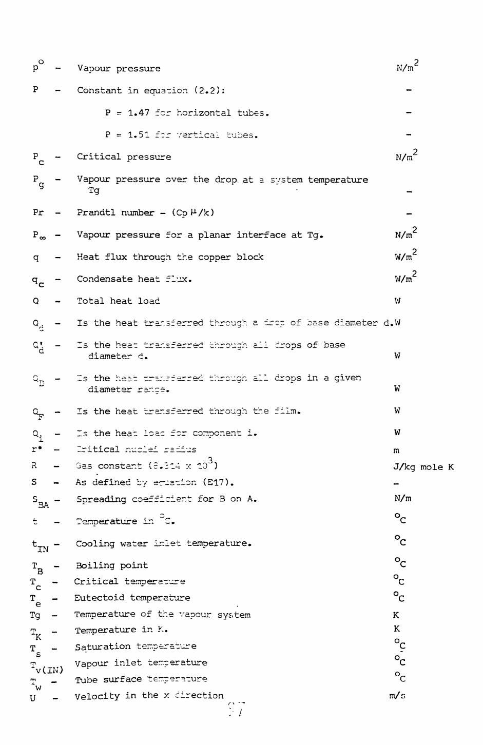
o 2 p - Vapour pressure N/m
P ~ Constant in equation (2.2):
P = 1.47 for horizontal tubes.
P = 1.51 f~r vertical tubes.
2P - Critical pressure N/m\*r
P - Vapour pressure over the drop, at a system temperature g Tg "
Pr - Prandtl number - (C
2 POO - Vapour pressure for a planar interface at Tg. N/m
2q - Heat flux through the copper blodc W/m
2q - Condensate heat flux. W/m c
Q - Total heat load W
Q . - Is the heat transferred throuch a ircr of case diameter d.W/~4 •*> -•wl
G*. - Is the hea~ transferred through ail crops of basediameter c. W
Q^ — ~s the he=.t c^r=-"-rferrec through ail dror>s in a givendiameter range. W
Q_, - Is the heat transferred through the film. W4.
Q. - Is the hea_ loac for conoor.ent i. Wi
r* - Critical nuclei r=cius m
R - Gas constant (5.214 x 10 ) J/kg mole K
S - As defined by er-a-i^n (E17).
S - Soreading coefficient for B on A. N/m 3A
— : Q
t - Tenperature in ^C. C
ot - Cooling water inlet temperature. C
T - Boiling point C
T - Critical terroera-ure C cT - Eutectoid temperature °C eTg - Temperature of the vapour sys.tem KT - Temperature in K. K
K o T - Saturation teir.cers-ure C
5 " o" T Vapour inlet terrcerature Cv(IN.) K ' 0
T _ Tube surface terrper=-ure Cw
U - Velocity in the x direction m/c••
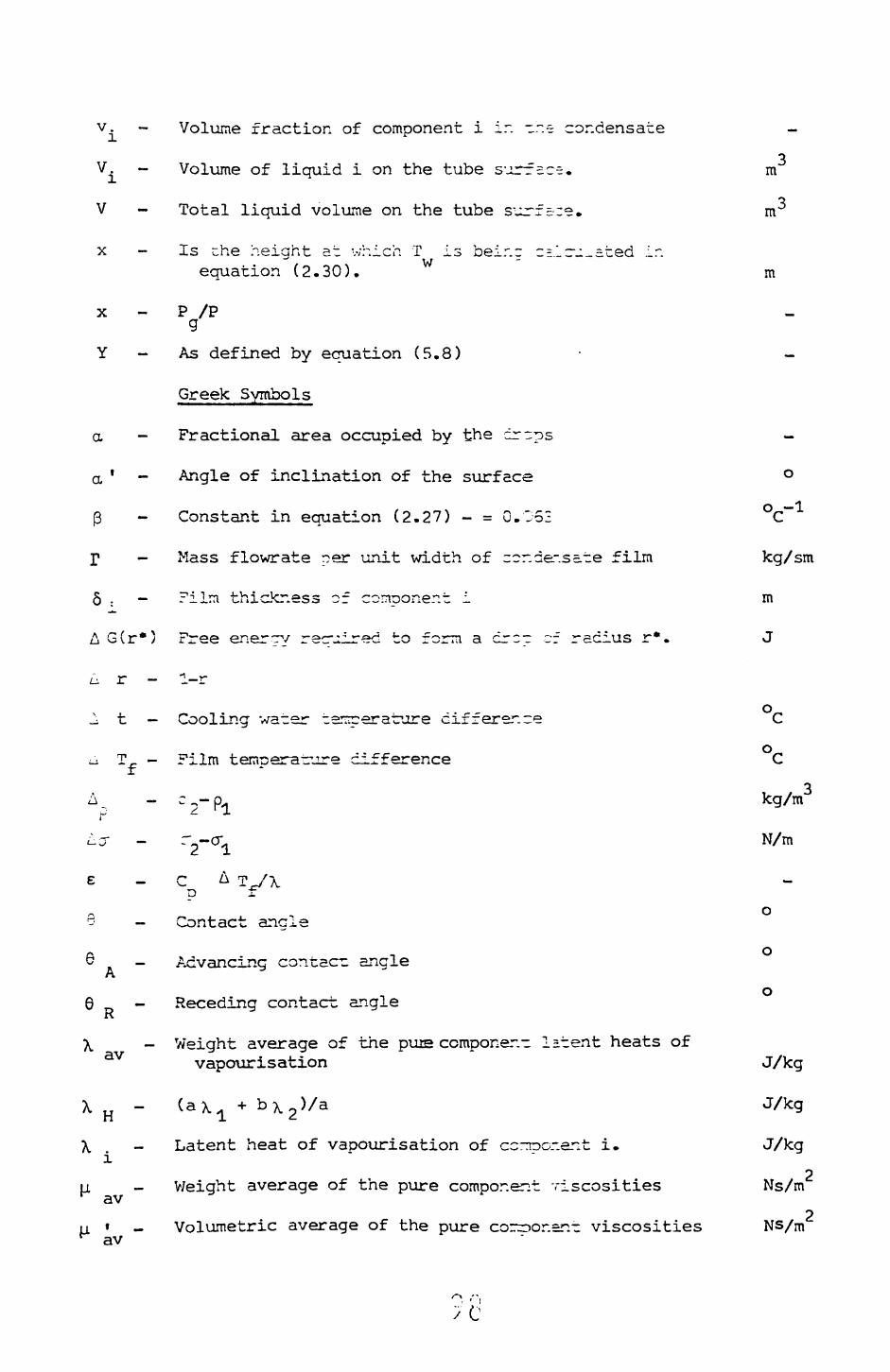
v. - Volume fraction of component i ir. -r.~ condensate -
V. — Volume of liquid i on the tube surrace. m
V - Total liquid volume on the tube surfare. m
x - is the height at which T is beir.g 2Eirj._ated ir.equation (2.30). W m
x - P /PgY - As defined by equation (5.8) • -
Greek Symbols
a - Fractional area occupied by the cr-ps -
a ' - Angle of inclination of the surface °
3 - Constant in equation (2.27) - = 0.052 °C~~1
I1 - Mass flowrate per unit width of zcr.de-.sate film kg/sm
5 . - Film thickness of conroonent i m
A G(r*5 Free energy reculred to form a crz- cf radius r*. J
." »*» ^^ *i >»•L^ JL j-""i.
oit- Cooling water ternperature differer.ce Co
LJ T - Film temperature difference C
-u*" ^
6 - Contact angle
© - Advancing contact anglef\
o6 0 - Receding contact angle
R
X - Weight average of the puts componer.- latent heats ofav vapourisation J/kg
X H - (ax a + bx 2 )/a J/kg
X - Latent heat of vapourisation of ccrTponent i* J/kg i
2LI. - V/eight average of the pure component viscosities Ns/m ^ av
u « - Volumetric average of the pure coinrjonsr.- viscosities ^ av

2 p. . - Viscosity of component i. Ns/rn
2JJL - Viscosity evaluated at the saturation temperature. Ns/mO
2l_i - Viscosity evaluated at the wall ter-perature. Ns/rn
p - v/eight average of -he pure conpcr.er.t densities. kg/p. * av x "*
p ' - Volumetric average of the pure corrpcnent densities Kg/m
p . - Density of component i. kg/m
cr. - Surface tension of component i. N/m
cr. . - Interfacial tension between liquids i and j. N/m
0 - Angle at which T is calculated in ecuation. (El). ow
0 - Labunstov physical property correction factor. - LI
T.
Subscripts
i - A or 1 and B or 2
A or 1 - Property of rr.e wall wetting phs.se,
3 or 2 - Property of the other phase.
Note
An overbar denotes a mean value
CO / /
APPENDIX A
PHYSICAL PROPERTIES
The following tables contain the correlations for calculating the
physical properties used ir. this study.
Table 1 contains correlations for wster, these were tested against
data obtained from Arnold (1970), the agreement between the data and
correlations is better than +2.0% within the temperature ranges quoted.
Table 2 contains correlations for toluene, these were tested against
data from various sources but mainly ESDU Items 74024 (1974), Item 74007
(1974), Item 66024 (1966), Jamieson et al (1973), International Critical
Tables (1930) and Timmermans (1950) and (1955). The agreement between
the data and correlations is better than _-5,C^c within the given temperature
ranges.
Table 3 contains correlations for tric-.Irroethylene, these were again
tested against various cEt- sources, i.e. E.5.3.U. Item 68024 (1968),
I ten 65024 (1966), J=r.ieson et al. (1973), 3y>ces (1968), Gallant (1970)
and Kirk and Othmer (1954). The agreemer.- between the data and correlations
is better than +5.0% (except for the liquid, heat capacity which is
within -ri::=) within the given temperature ranges.
r "\

TABLE A 1
PHYSICAL PROPERTY CORRELATIONS FOR WATER
Physical property Equation
Liquid density p in
kg/in3
p = 1000.0 - 45.05
Temperature range 0-220 C .
1.65
Liquid viscosity u in •
Ns/ra2 Temperature range 0-320 C
Liquid thennal conductivity
k in
W/s K
k = 0.638 - 7.76 x 10~6 (t - 125.0) 2
Temperature range 0-140 C
Sur~r2ce tension ~ in cr = 0.1032 - 7.2529 x 10~5T. - 1.6052 X 10~7T 2»» K
Tenperature r=r.ge 0-20C°C
xrjid specific heat c=r>=city
C in
C = 4179.0 + 1.232 x 10~2 (t - 40.0) 2
Tetnperacure range 0-200 C
Latarrt heat cf va
in J/lcg
= 2.5D13 x 105 - 2358.0 t - 5.254 x 10~5t4
Temperature range 0-240 C
Vapour pressure p In p = 23.2189 - 3842.567(228.6 + t)
Temperature range 0-240 C
Critical temperature
in °C
374.15 (647.30 K)
Critical pressure
P in N/m2
2.212 x 10 (218.3 atm)
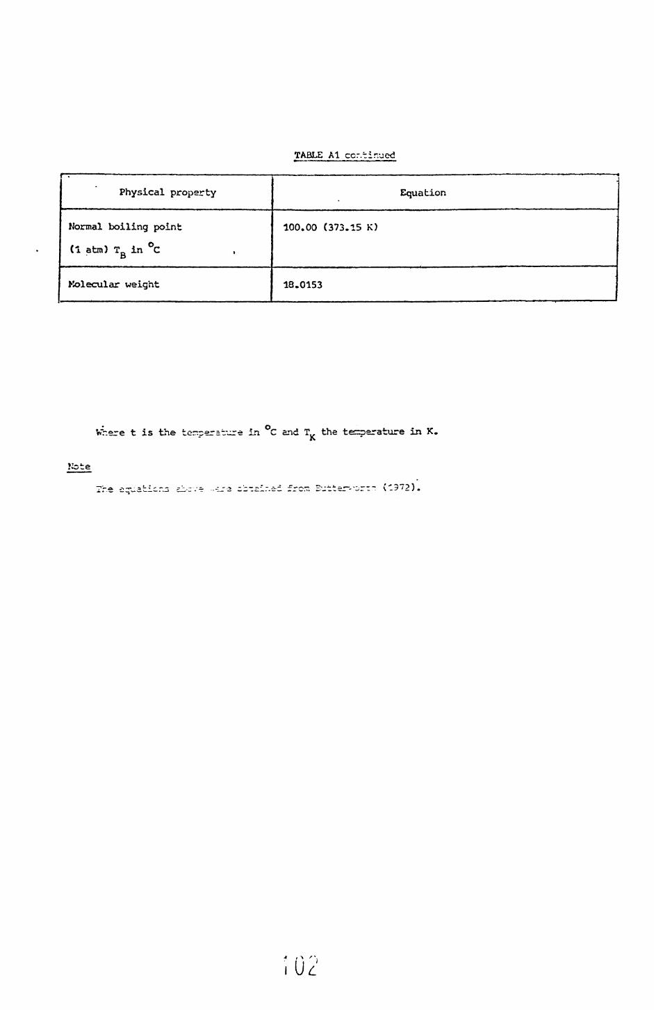
TABLE Al cor.tinued
r~. — —————————————————————————
Physical property
Normal boiling point
(1 atm) TD in °CO
Molecular weight
Equation
100.00 (373.15 K)
18.0153
Where t is the ter.per=t-^re in °C and T the temperature in K
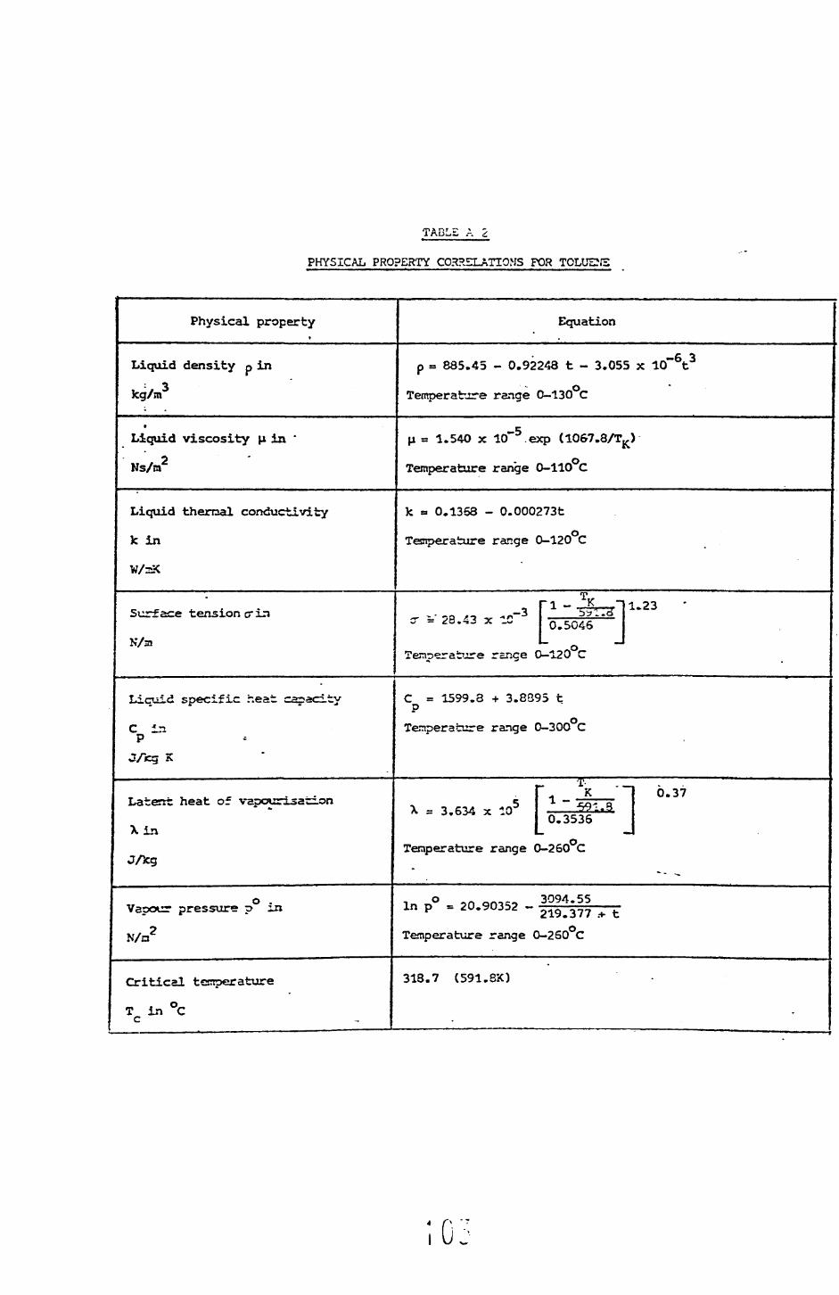
TABL£ A 2
PHYSICAL PROPERTY CORRELATIONS FOR TOLUE2JS
Physical property Equation
Liquid density p in
kg/n»3
p = 885.45 - 0.92248 t - 3.055 x 10~6t3• o
Temperature range 0-130 C
Liquid viscosity u in
Ns/ra2
u = 1.540 x 10 exp (1067.8/TK>
Temperature range 0-110 C
Liquid therrsal conductivity
Jc in
k = 0.1368 - 0.000273t
Temperature range 0-120 C
Surface tension <r ir»
N/a
=' 28.43 x ^-3 ririi-" I 0.5046
1.23
Temperature range 0-120 C
Liquid specific heat capacity
C in P
C = 1599.8 + 3.8B95 t P
Tenperature range 0-300 C
Latent heat of vapourisation
Xin
J/fcg
X = 3.634 x 10'1 - •591.90.3536
0.37
Teraperature range 0-260 C
Vapour pressure p in
N/n2
in p° = 20.90352 - 3094 ' 55219.377 .-*- t
Temperature range 0-250 C
Critical tssroerature
T in °C
318.7 (591.8X)

TABLE A2 cor.tirr^ed
Physical property
Critical pressure .
P in N/n2c
Npmal boiling point
. T^ in °C
Molecular weight
Equation
4.104 x 10⁶ (40.5 atm)
110.63 (383.73 K)
92.1418
. o,Where t is the tenperature in C and T the temperature is K.

TABLE A3
PHYSICAL PROPERTY CORRELATION'S FC?. TRiaiLOROETHYLENS
Physical property Equation
Liquid density p in
kg/ra3
= 1495.27 - 1.6493 t
Temperature renge 0-100 C
Liquid viscosity H in
Ns/ia2
.-5\i = 3.5714 x 10 •* exp (814.7/T..)f*Temperature range 0-80 C
Liquid therssal conductivity
k in W/ai C
k = 0.1275 - 0.000393 t
Temperature range 0-80 C
Surface tension crir.
N/a
0.0312 - 1.075 x 10~4t 1.25 x 10*~7t2
range 0-100 C
Liquid specific heat
C in^
J/kg K
C = 945.2 P
-v :.3374t
Ten:oerati!re rer.gs 0-100 C
Latent hect of var<«=is2ti2
in JAgX = 2.4702 x 10"
1 - K544.15
_ 0.3878
0.38
Teraperature range 0-100 C
Vapour pressure p ir. 3027.9ir, r, inp
Temperature range 0-100 C
Critical temperature
T in °C
271.0 (544.15 K)
Critical pressure
P in N/m2
5.016 x 10 (49.5 atm)
• r r

TABLE A3 contir.ued
Physical property
Normal boil
«, in °cing point •
Molecvilar weight
Equation
87.0 (360.15 X)
131.3893
Where t is the temper a'ture in C and T,, the tenroerature in K"
This equation was derived froa the data of Gallant (1970) and has not been compared against an independent data set.
APPENDIX B
Tabulated Results
The results obtained in the present study are tabulated in the
following seven tables. From the error analysis (see appendix G) a heat
balance error limit of +_ 15% was set. That is any experimental run
giving a heat balance error greater than jf 15% was rejected. Approximately
5% of the total number of runs were rejected;,
Table Bl requires further explanation here it can be seen that the
heat balances are all negative and of order -20%. This large error
was due to the initial method of measuring the condensate flowrate,
a consistently low reading being obtained. Since the condensate flowrate
was not a reliable method of determining the heat transferred in this
particular case the heat transferred to the cooling water was used to
determine the heat transfer coefficients.
The error in laea^uring the condensate flowrate was corrected for all
subsequent runs and for these the condensate flowrate was used to
determine the heat transfer coefficients.
107

APPENDIX B
TABLE B 1
DATA for the CONDENSATION of PURE STEAM
RunNo.
12 '
3
4
5
6
7
8
9
10
11
12
13
14
15
16
17
18
19
2C
T s°C
100.0
100.0
100.0
100.0
100.0
100.3
101.2
99.9
100.0
100.0
99.5
99.7
100.0
99.8
99.8
99.8
99.8
99.7
99.7
99.7
T w°C
86.0
86.9
89.2
90.1
89.7
90.3
92.1
91.6
83.7
85.3
84.8
86.5
89.9
90.4
91.5
92.4
92.0
92.6
93.9
84.0
ATF °C
14.0
"13.1
10.8
9.9
10.3
10.0
9.1
8.3
16.3
14.7
14.7
13.2
10.1
9.5
8.3
7.4
7.8
7.1
5.8
5.7
W/m
148400
152615
129319
123027
128812
119880
105851
101434
180441
174239
183089
170438
137178
132031
102198
93492
96361
89041
77546
78478
tlN °C
71.3
72.3
74.4
76.2
78.9
79.9
82.5
82.4
66.1
68.9
68.4
71.4
77.7
78.5
82.4
84.1
84.1
85.2
87.3
87.5
A t °C
3.10
3.22
3.29
3.22
2.38
2.20
2.04
1.95
3.19
3.09
3.02
2.84
2.38
2.30
1.82
1.69
1.61
1.51
1.38
1.39•i
F kg/s
0.8360
0.8240
0.6818
0.6671
0.9434
0.9491
0.9069
0.9113
0.9866
0.9818
1.0523
1.0405
1.0026
0.9926
0.9817
0.9614
1.0443
1.0194
0.9764
0.9746
Ht. Bal.
%
- 17.2
- 15.3
- 19.9
- 17.4
- 16.5
- 15.2
- 12.3
- 13.0
- 25.5
- 24.7
- 18.9
- 19.5
- 18.5
- 21.2
- 18.5
- 18.7
- 20.2
- 19.6
- 20.6
- 24.4
h W/m2°C
10600
11650
11974
12427
12506
11988
11632
12221
11070
11853
12455
12912
13582
13898
12313
12634
12354
12541
13370
13768
hlsW/m2°C
11378
11595
12205
12470
12345
12449
12784
13041
10927
11233
11233
11563
12416
12621
13037-
13465
13267
13608
14327
14415
108

TABLE B 2
DATA for tho COfOSNSATT :•'.' :f TOLUENE
Run No.
123
-.4
56789
10ll"
12
13
15
1517
13
19
20
21 i
T °C
110.7
110.2110.2110.2110.2109.8109.3110.0110.2
110.7
110.3
111.2
110.6
111. 2
111.1
110.9111.0
110.3110.3
110.4
110.2
°C
100.4
77.3
79.281.084.7
90.6
93.094.784.7
93.996.699.7 99.1ei.o37.0
8?. 9
95, S73.5
54.2 92.43-5 - '
\
A°cF
10.3
32.931.029.225.519.215.3
15.3
25.515.313.7
11.5- , -
~ ' Z.
21- - '
31. ~25-1~Lz.-,2 '
lr-5 ;
£21,349.8
48,159.0
45,570.0
41,656.739,191.031,791.4
29,193.4
26,441.5
42,493.3
31,063.227,130.4
23,947.624,C31.4
Ilir^S
35.952.5
",^5.947,422.7
33,197.430,245.2
°cN
98.8
73.675.477.1
81.187.189.9
91.581.190.5
94.0
97.1
96.474.5
81.7
85.0
92.4
73.1
79.5
83.4
90.0
A t °C
0.45
0.87
0.89
0.83
0.79
0.83
0.75
0.79
0.73
0.630.61
0.66 0.57^ ._1.2"
1.20
0.94 !
1.15
0.95
0.92
F 5cg/s
0.7310
0.8473
0.3148
0.8376
0.8411
0.7504
0.7232
0.65CO0.3180
0.69300.7431
0.6774
0.6533;"!!!5J.5342
0.52530.5733
0.6723
0.5407
0.5363
Ht. Bal.ef J»
- 9.4- 12.2- S.4- 3.7- 3.0
14.67.2
U.4- 14.1- 12.6- 3.0
5.9 5.0
— 2.1
- 1.3
. 2.7
- 5.2- 5.7
- 5.8
- 9.9
- 6.8
h W/n2 °C
2072.8
1463.8
1470.0
1426.6
1536.91655.81738.01728.21666.61849.01984.72082.4 2094.91540.7
1703.41712.5
1979.6
1496.3
1603.1 1844.3
1839.1
W/ra2 °C
1834.41384.61404.61425.01472.1.1578.01630.21667.91472.81627.81712.01783.7 1785.61411.6 1492.61541.91658.21397.1-1464.6 1602.71637.6
09

TABLE B 3
DATA for the CON'DEHSATION of PUT.E Tr-ICKLCROETKYIZNE
Run No.
1.2345678~
91011 ai-i
13
T•s87.087.087.066.686.686.686.786.8
35.9
55.8
££.9S£.337.0
T w°C
83.282.080.266.363.070.271.0
73.0
75.377.3 •ra o/O.:7
£0.3
82.9
.£TF °C
3.85.06.3
19.818.616.4
15.7
13.3
11.6? ^^ *"
= 0-» » W
S m. ~.
-c » _
^cW/ra2
9,16610,66013,41625,72024,03722,681
21,792
21, 349
17,354'5.C?3 ?13,552
3,597
fc!N °C
81.8
80.2
77.962.764.066.667.469.3
72.3
74.9
75.573.9
81.5
*t °C
0.34
0.42
0.510.830.79
0.77
0.76
0.68
0.65
0.54
0^4• *s^
0.44
0.34
F
:<g/s
0.4574
0.4813
0.4562
0.5412
0.5412
0.5445
0.5406
0.5404
0.54350.5295 0.^*^1
3.51 IS
c,:-s
Ht. Bal. %
6,5
9.06.40.12.15.87.5
- 0.213.1
10.3
11.9
- 5.02.2
h W/m2 °C
2412
2132
1973
1299
1295
1333
1388
1547
1540
1531 1744
2013
23S5
\ W/m2 °C
2279
2137
1977
1533
1556
1603
1619
1672
1741
1825
1907
2041
2245
10

TABU: n -1
DATA for the CONDENSATION OP STEAM-TOLUE:.r:: MIXTURES ON AN OXIDISED COPPER Tt'OE
Run No.
1
2
345 6
789
10111213-
1415161718192021222324252627282930-
31323334353637
T °°c
84.484.584.684.984.5 84.583.683.784.484.184.183.984.284.384.384.484.3 84.384.384.384.484.484.384.283.983.884.084.784.784.884.884.884.784.784.985.084.6
T w°C
62.7
60.160.265.562.0 62.565.770.975.075.276.472.273.674.170.471.163.3 69.359.860.964.249.151.550.951.854.956.974.376.477.379.979.880.080.680.881.280.2
* TF °C
21.724.424.419.422.5 22.017.912.89.38.97.7
11.710.610.213.913.315.5 15.024.523.420.235.332.833.332.128.927.19.98.37.54.95.04.74.14.13.84.4
W/si
73,93895,18794,20181,06195,627 95,96076,51760,49046,95645,22141,24152,00759,39258,06977,43775,78380,135 80,10099,27496,08097,546
123,479120,999108,525114,982117,623114,49857,91550,59741,27330,89932,28026,46127,08126,61326,46324,996
£.54.050.149.656.851.7
52.557.865.571.271.672.865.864.665.261.762.659.7 60.348.049.552.533.436.337.637.440.542.767.369.971.976.376.176.677.577.778.377.2
At. °C
1.541.751.74
1.451.67 1.601.441.040.730.700.821.451.941.901.561.561.64 1.621.941.922.022.322.332.102.252.302.271.511.311.140.790.850.820.770.790.770.65
Fkg/s
0.87270.95950.93040.95790.9834 0.98320.9722
' 0.96340.96300.96030.74590.64960.50780.50380.82260.83190.8848 0.87580.90930.91120.90401.01111.01060.99410.98010.97960.97910.66950.66900.63330.63240.63240.62930.63520.62290.62580.6679
lie. Dal.
%
4.71.5
- 1.3- 1.6- 1.7 - 5.5
5.9- 3.5- 12.4- 12.9- 13.5
4.8- 4.9- 5.1- 5.0- 1.5
4.21.72.44.87.39.3
12.110.610.19.8
11.70.0
- 0.60.3
- 7.4- 4.9
10.73.67.14.30.6
COOT. COKP.W % /W Toluene
83.078.879.580.180.1 80.1>9.878.779.581,581.980.778.278.578.078.380.8 80.083.384.780.480.980.682.4 -80.880.681.278.980.782.384.083.883.382.681.079.884.2
h h (Tol.) W/m2 °C ! W/n2 °C
34073901386141784250 436242754726504950815355444556035693557156985170 534040524106.482934933689325935824070422558506096550363066456
- 56306605649169645681
15451499149915901530 153916251770191719432014181018621884173217531685
*
17001497151615731359133613801394143314581887197120212249223622722357235924012322
TVo (IN)
97.996.496.396.898.3 98.997.599.998. 5
100.698.798.399.399.799.299.3
100.0 100.499.2
100.8100.895.296.798.896.497.397.499.499.9
102.7104.7104.S103.1102.9101.9102.4101.7
111
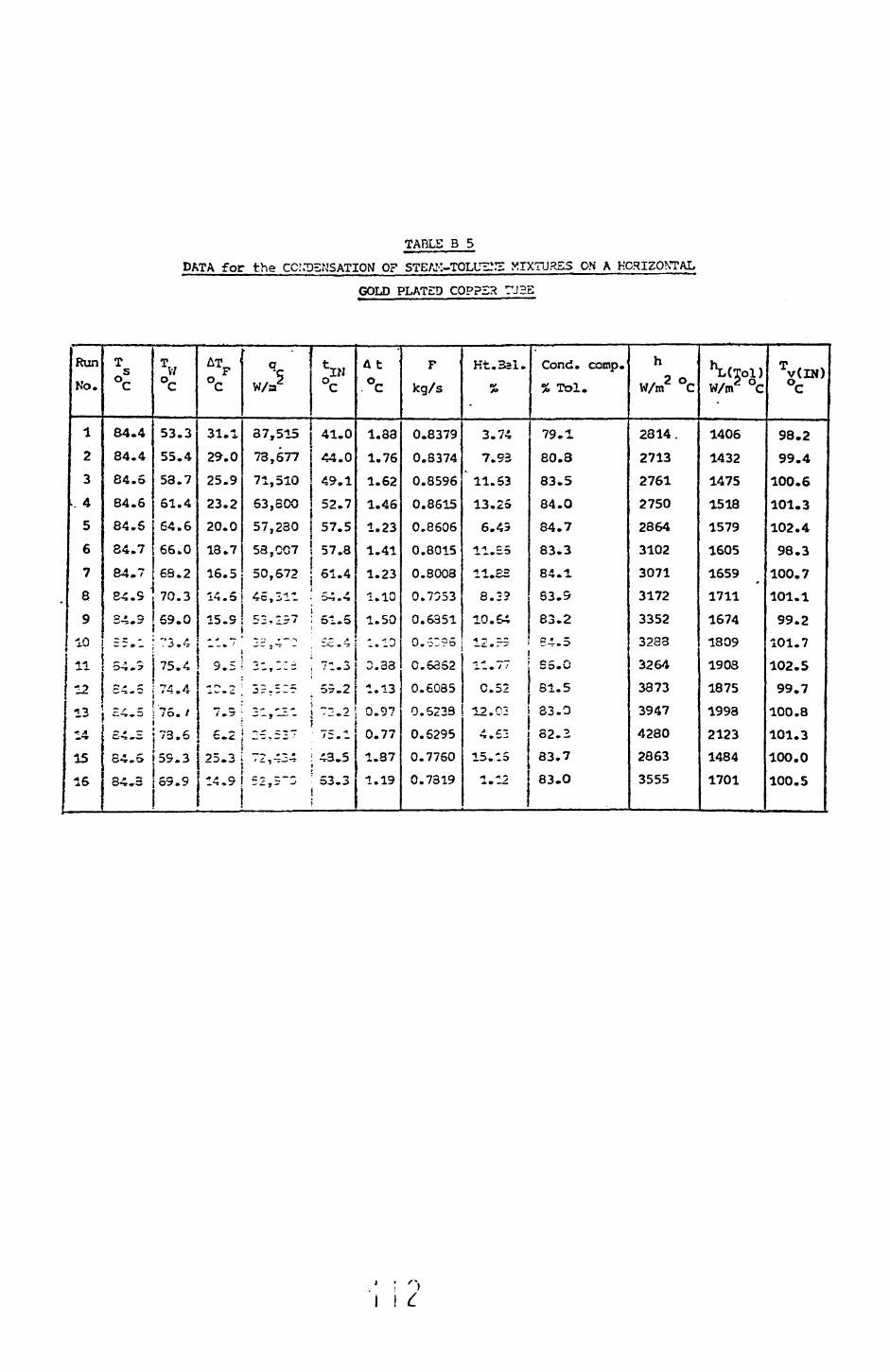
TABLE B 5
DATA for the CCM35KSATION OF STE/J-'-TOLUZ!^ MIXTURES ON A HORIZONTAL
GOLD PLATED COPPER TUBS
Run N'o.
123
.. 4
56
789
; 10
11
12
13* A^-*
1516
T°l
84.4
84.4
84.6
84.6
84.584.7
84.7
84.S
S4.3c ~ -— - » _
54.5O * £ C^x* »
C.-»» 3
£4.3
84.5
34,3
T V7°C
53.355.453.7
61.464.6
66.063.270.3
69.0
73.4
75.4~rf A I *i .*x
75. /
73.6
59.3
69.9
z\Tp °c
31.129.025.923.220.0
18.7
16.5
14.5
15.9<• ^ •—
9.5-^ r> -v"*" ** "~
7.5
6.2
25.3
14,9
V/s
37,515
73,577
71,510
63,300
57,230
58,007
50,672
45,311
^ • ^.3 *— p r — -~*
-„ -- -
3?.5I5
— -« — - -
2£ T 5I7
72,424
52,5~3
'?'
41.0
44.0
49.1
52.7
57.5
57.8
61.4
54.4
51.5c~ .«
71.3
55.2
T2.2»•f
75.1
43.5
53.3
At °C
1.33
1.761.621.46
1.231.41
1.23
1.10
1.50- -! '"V
3.33* n *• u
0.97
0.77
1.37
1.19
F kg/s
0.8379
0.8374
0.8596
0.8615
0.8606
0.8015
0.3008
0.7553
0.6351
0.5:96
C.63S2
0.6085
0.5233
0.6295
0.7760
0.7319
Kt.Bal.0»f>
3.74
7.93
' 11.63
13.25
6.43
11.35
11.ES
8.2?
10.64't ™ Z-C.
11. / ••
0.52
12.02
4.62
15. IS
1.12
Cond. coop. % Tol.
79.1
80.383.584.0
84.7
83.384.1
63.9
83.2S-i.5
SS.G
31.5
33.0
82.2
83.7
83.0
h W/m2 °C
2814.2713276127502364
31023071317233523233
326438733947428028633555
^(Tol) W/m2 °C
1406143214751518157916051659
»
1711
1674
1809
1908
1875
1993
21231484
1701
Tv(lN)
98.299.4
100.6101.3102.498.3
100.7101.199.2
101.7102.5
99.7
100.8
101.3
100.0
100.5

Table B 6
DATA for the CONDENSATION OF STEAK-TRICHLORCETHYLENS MIXTURES ON A HORIZONTAL
OXIDISED COPPER TUBE
Rur
No.
1
2
3
4
5
6
7
6
9
10
11
12
13
14
15
16
17
18
T °C
.74.9
73.5
73.5
73.5
73.3
73.3
73.4
73.4
73.2
73.1
73.2
73.5
73.6
73.6
73.6
73.6
73.6
73.5
T W°C
69.7
59.0
63.1
65.1
62.6
64.7
48.3
51.7
53.0
61.2
62.5
64.9
67.9
69.1
56.9
61.0
54.6
57.3
ATf °C
5.2
14.5
10.4
8.4
10.7
8.6
25.1
21.7
15.2
11.9
10.7
8.6
5.7
4.5
16.7
12.6
19.0
15.2
«c W/m2
26,572
41,862
40,248
35.624
52,752
43,757
70,532
69,115
49,155
43,087
41,161
41,902
32,692
27,447
45,539
48,959
57,539
57,316
£65.5
52.3
58.2
60.6
54.4
57.8
37.3
41.2
49.7
54.0
55.1
57.9
62.6
64.3
48.6
51.7
44.6
47.8
At6c
0.88
1.24
0.88
0.80
1.47
1.28
1.80
1.74
1.60
1.44
1.45
1.41
1.06
0.94
1.52
1.81
1.77
1.79
F
kg/s
0.5302
0.6482
0.9024
0.9083
0.6718
0.6713
0.6827
0.6822
0.5501
0.5460
0.5459
0.5492
0.5450
0.5375
0.5502
0.5204
0.5475
0.6371
Ht.Bal.
%
1.5
10.8
13.1
-
7.7
12.4
- 0.1
1.4
3.2
4.5
10.3
6.2
1.5
5.5
5.5
10.6
- 3.0
14.3
Cond.comp.
% W/w Trich
92.5
94.0
93.9
93.7
,93.1
.92.9
93.4
93.0
94.0
93.8
93.7
93.8
94.1
95.0
93.9
93.5
93.5
93.4
h W/m2°C
5110
2887
3870
4241
4931
5088
2816
3185
3232
3609
3585
4884
5705
6127
2720
3880
3024
3538
^(Trich) W/ra2°C"X
2182
1703
1844
1942
1832"
1931
1492
1545
1683
1785
1834
1932
2133
2266
1643
1759
1593
1658
Tv(IN) °C
90.0
74.2
74.2
74.7
83.2
83.3
75.4
76.1
73.8
73.9
74.2
76.0
75.1
74.8
74.7
77.3
78.1
89.7
113

TABLE 3 7
DATA for the CONDENSATION OF STEAM-TRICriLOROETHYLENE MIXTURES ON A HORIZONTAL
GOLD PLATED COPPER TUBE
RunNo.
1
2
3
4
5
6
7
8
9
19-1112
1314
15
T°?
73.3
.73.5
73.4
73.8
74.4
73.8
73.9
74.1
73.8
73.9
73.8
73.7
73.5
73.7
73.2
T w°C
56.1
59.8
63.1
71.1
67.3
65.4
65.2
66.9
67.9
62.5
67.5
48.6
52.9
57.7
59.6
£17.2
13.7
10.6
2.7
7.1
8.4
8.7
7.2
5.9
11.4
8.3
25.1
20.6
16.0
13.6
qc
W/ra2
40,403
34,099
26,670
10.457
23,629
24,427
24,272
22,414
28,074
27,222
21,762
57,173
50,931
41,124
38,896
fc!N °C
49.9
54.6
59.2
69.1
63.2
60.3
60.3
62.6
64.1
57.2
51.5
40.4
45.0
51.3
52.6
At °C
1.20
0.97
0.78
0.38
0.85
1.06
0.85
0.74
0.65
1.00
0.76
1.54
1.46
1.22
1.12
F kg/s
0.6015
0.6009
0.5970
0.5296
0.4594
0.4597
0.5493
0.5490
0.5452
0.5363
0.5347
0.6891
0.6798
0.6730
0.6483
Ht. Bal.
%
2.87
- 1.49
0.43
11.69
- 5.06
14.53
11.01
4.81
12.22
12.87
6.76
6.96
11.96
14.46
7.34
Cond. Comp.
% W/w Trich
93.8
92.5
94.2
94.5
94.5
93.9
92.8
94.0
94.3
94.0
93.7
92.9
94.5
93.6
94.6
h W/m2°C
2349
2489
2516
3873
3328
2908
2803
3126
3048
2382
2616
2275
2470
2572
2860
hL W/m2°C
1633
1714
1860
2606
2044
1967
1952
2044
2142
1825
1972
1513
1586
1684
1753
Tv(IN °C
88.6
89.9
90.6
91.9
91.0
91.1
90.1
90.7
90.9
88.6
90.8
91.4
92.5
92.5
91.5
114
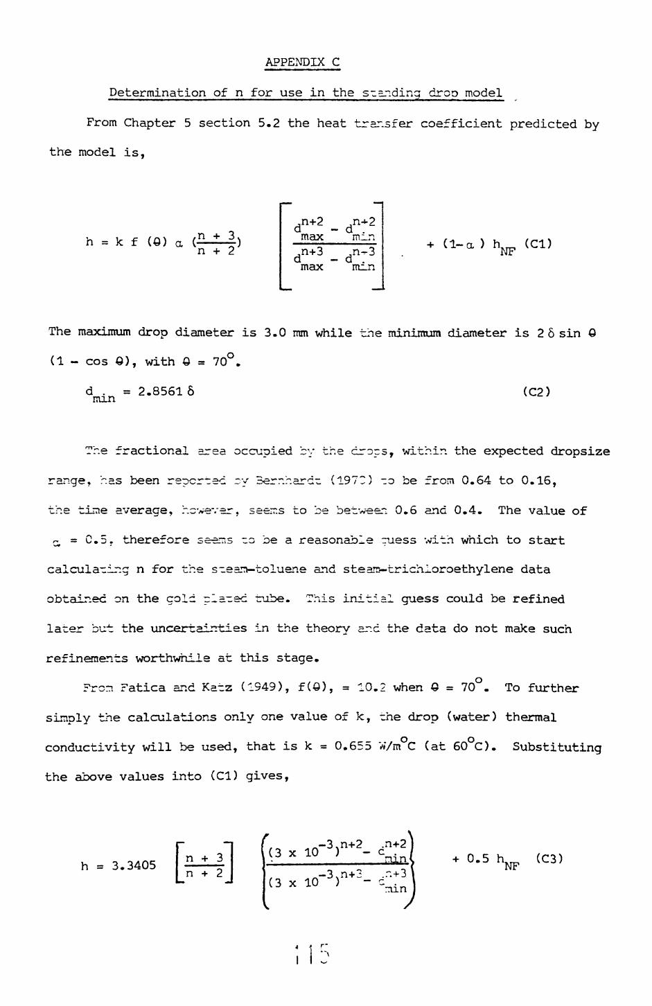
APPENDIX C
Determination of n for use in the s~ending drop model
From Chapter 5 section 5.2 the heat transfer coefficient predicted by
the model is,
h = k f a n + 2
,n+2 max d .mn+3 max d . linn
(1-a) (CD
The maximum drop diameter is 3.0 mm while the minimum diameter is 2 6 sin
(1 - cos S), with 0 = 70°.
<C2)
The fractional area occupied by the crops, within the expected dropsize
range, has been reported ~y Berr.hard- (197C) -o be from 0.64 to 0.16,
the tine average, however, seerr.s to be between 0.6 and 0.4. The value of
a = C.5. therefore seems -o be a reasonable ruess with which to start
calculating n for the s-ean-toluene and steans-trichioroethylene data
obtained on the gold pla-ec tube. This initial guess could be refined
later but the uncertainties in the theory and the data do not make such
refinements worthwhile at this stage.
From Fatica and Ka~z (1949), f(Q), = 10.2 when Q = 70°. To further
simply the calculations only one value of k, rhe drop (water) thermal
conductivity will be used, that is k = 0.655 W/m°C (at 60°C). Substituting
the above values into (CD gives,
h = 3.3405 n + 3 n + 2
(3 0.5 (C3)
nun
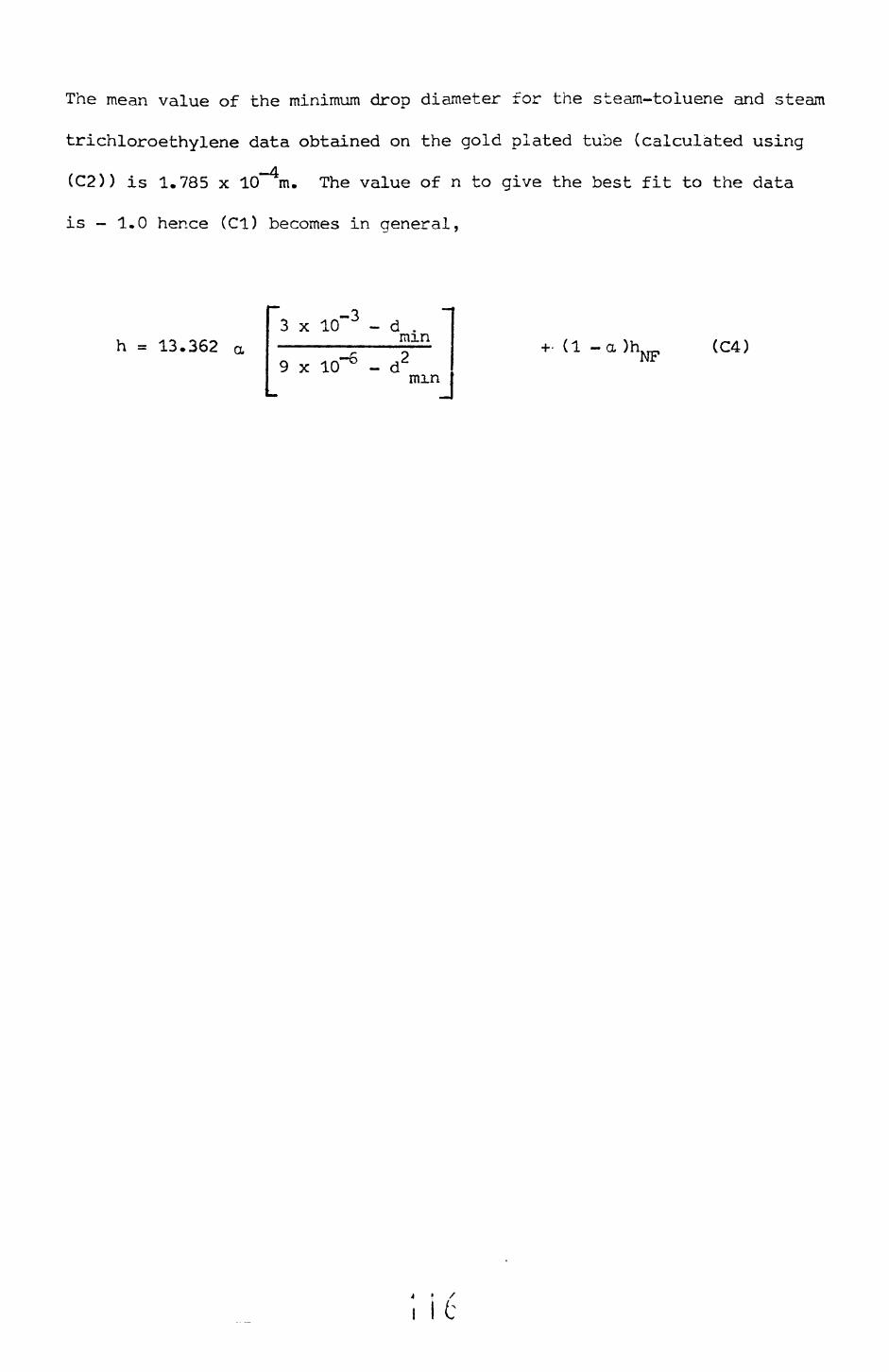
The mean value of the minimum drop diameter for the steam-toluene and steam
trichloroethylene data obtained on the gold plated tube (calculated using
(C2)) is 1.785 x l(T4m. The value of n to give the best fit to the data
is - 1.0 hence (Cl) becomes in general,
h = 13.362 a3 x ICf3 - d .mm
9 x 10"6 - d2mm
+• (1 -a )hNF (C4)
4 • /
I It

APPENDIX D
Nucleation barriers in immiscible liquid condensation
When condensing vapour mixtures of immiscible liquids the possibility
exists that if a continuous film of one liquid covers the surface the other
condensing liquid may not.be able to condense until a resistance to
nucleation has been overcome.
The homogeneous rate of nucleation of a liquid from a supersaturated
vapour is given by Hill et al (1963) as
M -AG(r
where I is the rate of r.ucleation, k Bolnznans constant, T the vapour
tenner ature. M the molecular weiaht. N Avocacro's number, pT the liquid » T 0 7 r^ ^
drop density, cr the liruic: ircp surface -er.sion and ^_G(r*) the free energy
required for nucleaticn of a crop. For the homogeneous case aG(r*)
is given by (Hill et al (1353); as,
A G(r») = - " ~ r» 2 . (D2)
Turnbull (1950) has shown that the free energy required to form a drop
which is part of a spherical segment is
^ GCr») = -|-cr*-(2 + cos 0) (1 - cos £) 2/4 (D3)
= AG (r*)<:,rl
where AG(r*) is defined by equation (D2), 6 is the contact angle and H
2 C = (2 + cos G) (1 - cos 6) /4. Combining (Dl) and (D3) gives
2P M 2(jN -4 -Ttr* Cexp '
I ! /

but r* = 2 <r M/ pL RTIr.CP /P«> ) (Hill et al. ^1963) hence
I =M 2 O-M -j-
> ('o ^L
-K M-16 K (D5)
3kTc ?l R2(ln?g/? co
The part of equation (D5) which is of greatest interest for this
study is C, that is (2 + cos 0) (1 - cos G) 2/4. Consider a steam-toluene
mixture, if the water forms the continuous phase we must consider the
condensation of toluene onto the water surrace. The contact angle for
most organics on water is zero or near zero, from equation (D3) this means
the free energy for the formation of a drop is zero, or near zero, that
is there is no barrier to the condensation of toluene onto the water
surface
However, if we consider steam condensing on toluene it is known that
water v/iii not spread en a roluer.e surface (or indeed on most organic
liquids with which in is immiscible) and hence a finite contact angle
between -he two liquids will exist. Since there are no data available
for the required cor.tacn =ncles a range of contact angles will be considered.
Consider the sys-erti shown in figure Dl. The problem is to calculate
T such that the nucleation rate 1 is significant. In this case P is i 9
the parnial pressure of the steam in the gas phase (and thus also its
vapour pressure), thus for a eutectic vapour mixture.
Pg=760 (1-0. 444) =42 3 rnn Kg = 5.6394 x 10"d\T.es/cm2 ,Tg=84.34°C=357.49K, PL = 0.9692 gni/cm3 (at 84.34°C), N = 6.023 x 10 g mole " (Avogadros constant),
Ifi 2 k = 1.3308 x 10 ergs/K (Boltzmans constant), cr = 61.7 ergs/cm•j
(at 84.34°C), R = 8.314 x 10 ergs/g moleKCGas constant) and M = 18.0.
equation (D5), 1=1.4591 x 10 26 exp L -31.13 C /(in x) 2 ], CollierFrom1 "1
(1972) gives a rate of 10 -10 as being a significant nucleation rate,
thus taking the smaller value
i c
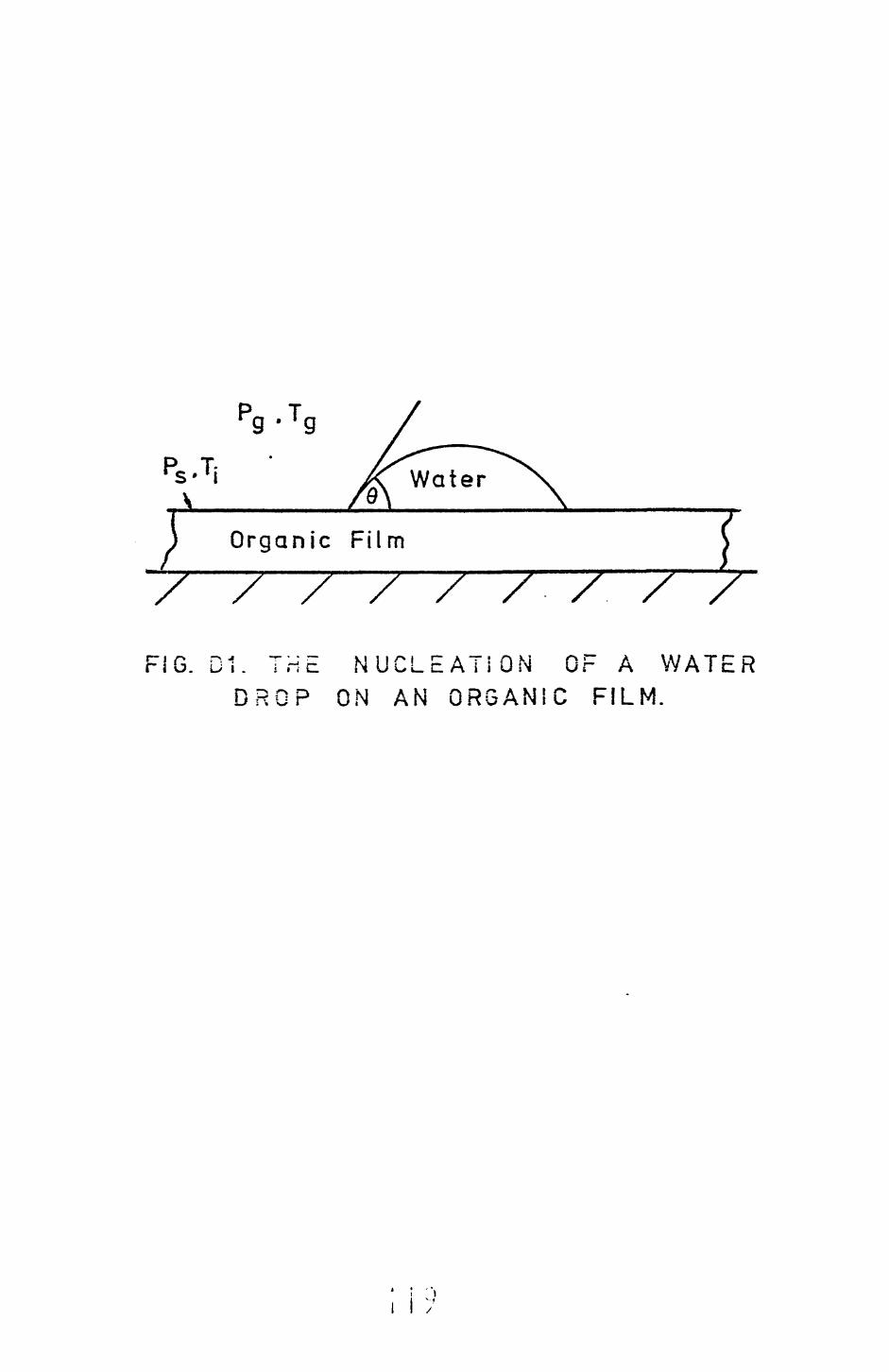
pg - TgP T- rs» l i
V.
Organic Film
F! NUCLEATiON OF A WATER DROP ON AN ORGANIC FILM.
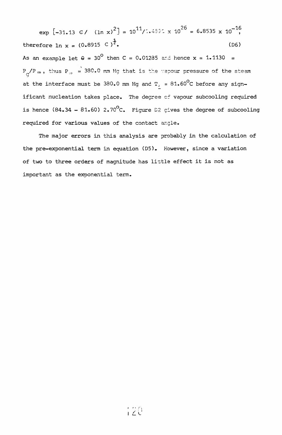
exp [-31.13 €/ (in x) 2 ] = lO11/-*-^'. x 1Q 26 = 6.8535 x
therefore In x = (0.8915 C ) 2 . (D6)
As an example let Q = 30° then C = 0.01235 sr.d hence x = 1.1130 =\
P /P co i thus P.. = 380.0 mm Ha that is the vaoour pressure of the steamg _0 ^ .
at the interface must be 380.0 mm Hg and T_. = 81.60 C before any sign
ificant nucleation takes place. The degree cf vapour subcooling required
is hence (84.34 - 81.60) 2.70°C. Figure D2 gives the degree of subcooling
required for various values of the contact ar.gle.
The major errors in this analysis are probably in the calculation of
the pre-exponential term in equation (D5). However, since a variation
of two to three orders of magnitude has li-tle effect it is not as
important as the exponential term.
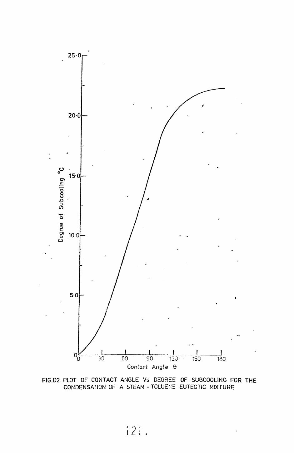
25-0,
oo
o o oJ3•3to
O p
O Q
20-0
15-0
°* 10-0
0Contact Angle 6
FIG.D2. PLOT OF CONTACT ANGLE Vs DEGREE OF-SUBCOOLING FOR THE CONDENSATION OF A STEAM - TOLUtNE EUTECTIC MIXTURE
2 > I .

APPENDIX £
The Effect of Variable V/all Ter.-eri~.Lre on the
Laminar Film Condensation of =. r-.-re Vapour
The following analysis is an attempt -o determine the effects of a
non-uniform wall temperature on the condensin; film heat transfer co
efficient. The assumptions made are those of >russelt (see chapter 2
section 2.2), here however, the wall temperature- is not constant but is
given by the empirical correlation of Salov am Danilov (1975) i.e.,
T = T + C. cos 0 (El) w w 1
where T is the mean wall temperature, T ihe accrual v/all temperature atV* W
angle 0 and C a constant.
From equation (El) it is apparent tr.a~
:os .2) (E2)
putting :c = C / £!_,_ then equation (E2) becomes
= AT C 1 - „ cos 0) % (E3)
The coordinate system used is shown in figure El. The momentum
equation can be reduced to
d2usin ^ = -^ (E4)
Integrating equation (E4) gives
, I LL

FIG. Et. CO-ORDINATE SYSTEMFOR THE NON ISOTHERMAL
WALL ANALYSIS.
I L
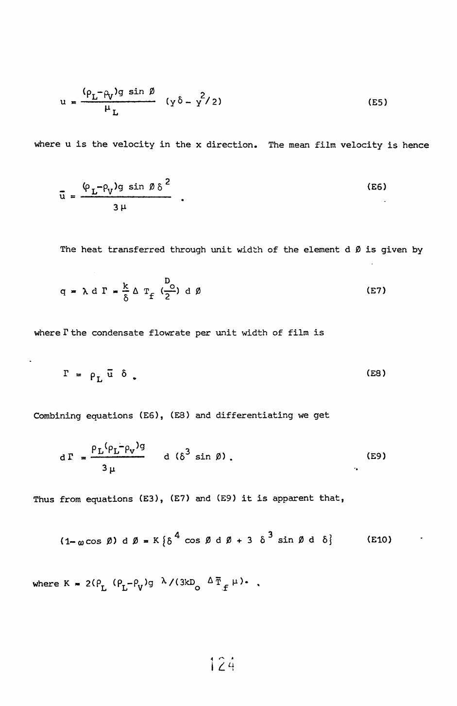
(p T -oJg sin 0 - -l£-—————— (yS-y2/ 2 ) (E5)
where u is the velocity in the x direction. The mean film velocity is hence
Cp L-pv )g sin 08 2 (E6)
The heat transferred through unit width of the element d 0 is given by
Dq- \dr-~AT. (~) d 0 (E7)
o * ^
where T the condensate flowrate per unit width of film is
p u 6 (E8)
Combining equations (E6), (E8) and differentiating we get
o d(63 sin0). (E9)
Thus from equations (E3), (E7) and (E9) it is apparent that,
(1-cocos 0) d 0 » K J5 4 cos 0 d 0 + 3 6 3 sin 0 d 6J (E10)
where K - 2(PT (PT -Pv >g x /(3kD AT u). %Li Ll V O -I

Putting K 6 4 = z and noting that 3 83 d 8 = -|d (
equation (E10) reduces to
dZ 4 Z cot 0 4 oocot 0 4 cosec 0 + ———3——— + ——3———— - ——3———— (Ell)
the solution of this ordinary differential equation being,
3 sin (sin ^0 - oasin ^0 cos 0) d 0 „ (E12)0
The condensate film heat transfer coefficient is hence given by
h - ~ = k K 4/Z 4 (E13)
However, it is not tr.e sisolu^e value which is of interest but the value
relative to the Xusseit prediction for an isothermal wall. Following
the derivation above -.vith the isothermal wall assumption gives
> N = :< KVZ * (E14)
where
_ . 3 sin . 0in 0 d 0.
0(E15)
Combining (E12),E(13), (E14) and (E15) gives
N1 - 0) (E16)

where r 4S « ————S--——— / sin T 0 d 0. (E17) 3 sin 4/ 3 0
The ratio of the mean heat transfer coefficient is given by
r /-7l
h d 0 / J0 hN d 0.VH- * J" h d 0 / yn h%T d 0. (E18)
Using equations (E12), (E13), (E14), (E15), and (E18) it can be
shown that,
0/S (Elf)
Since Chaddock (1957) has shown that
~ J^ d 0/S* = 0.805542, equation (E17) becomes
« 0.39515 J0 d 0/ [s-co], (E20)
Equations (E16) and (E20) have been solved numerically (using
Simpsons rule) for various values of oo and 0, the results are shown in figures
E2 and E3 respectively.
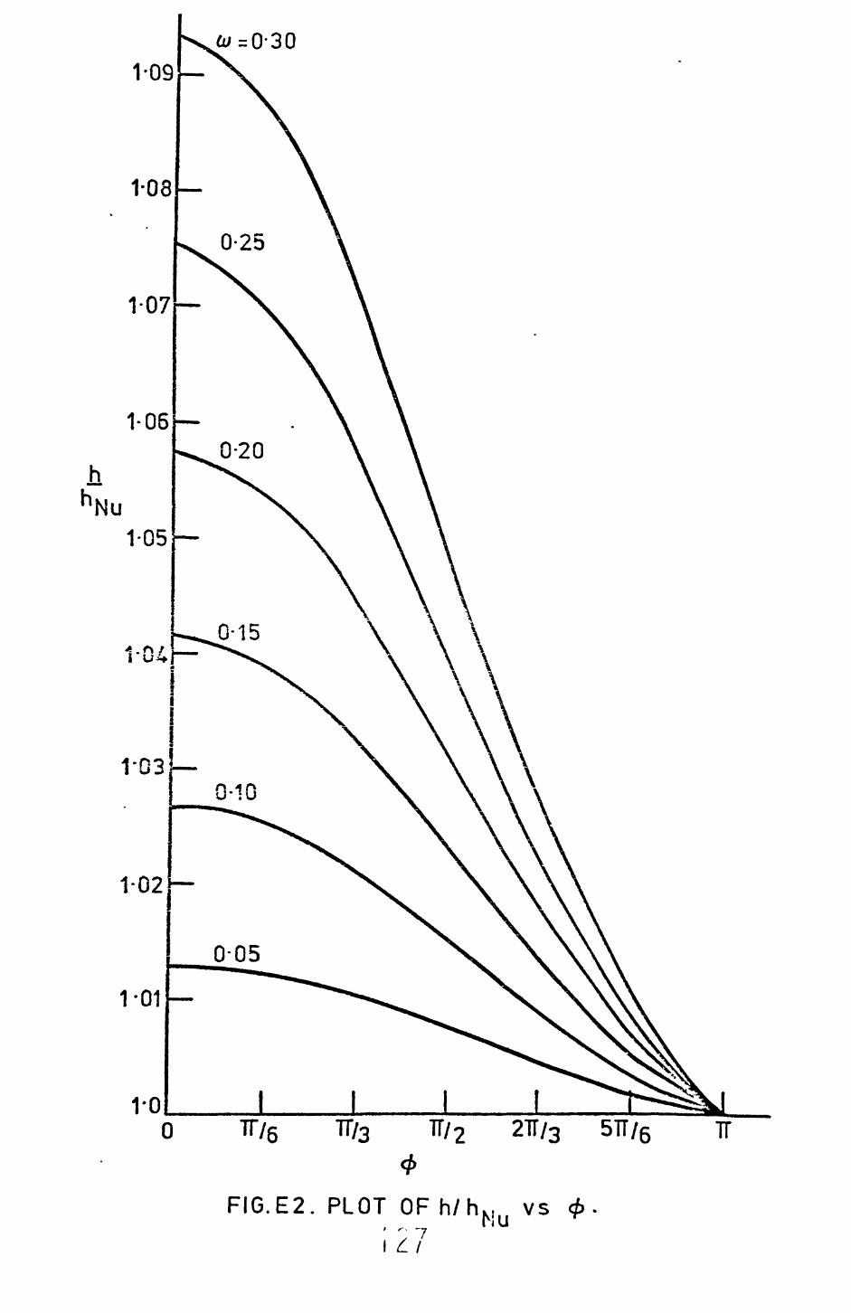
0 7T/5 7T/3 TT/2 21T/3 5TT/6 TT*
FIG.E2. PLOT OF h/fu... vs
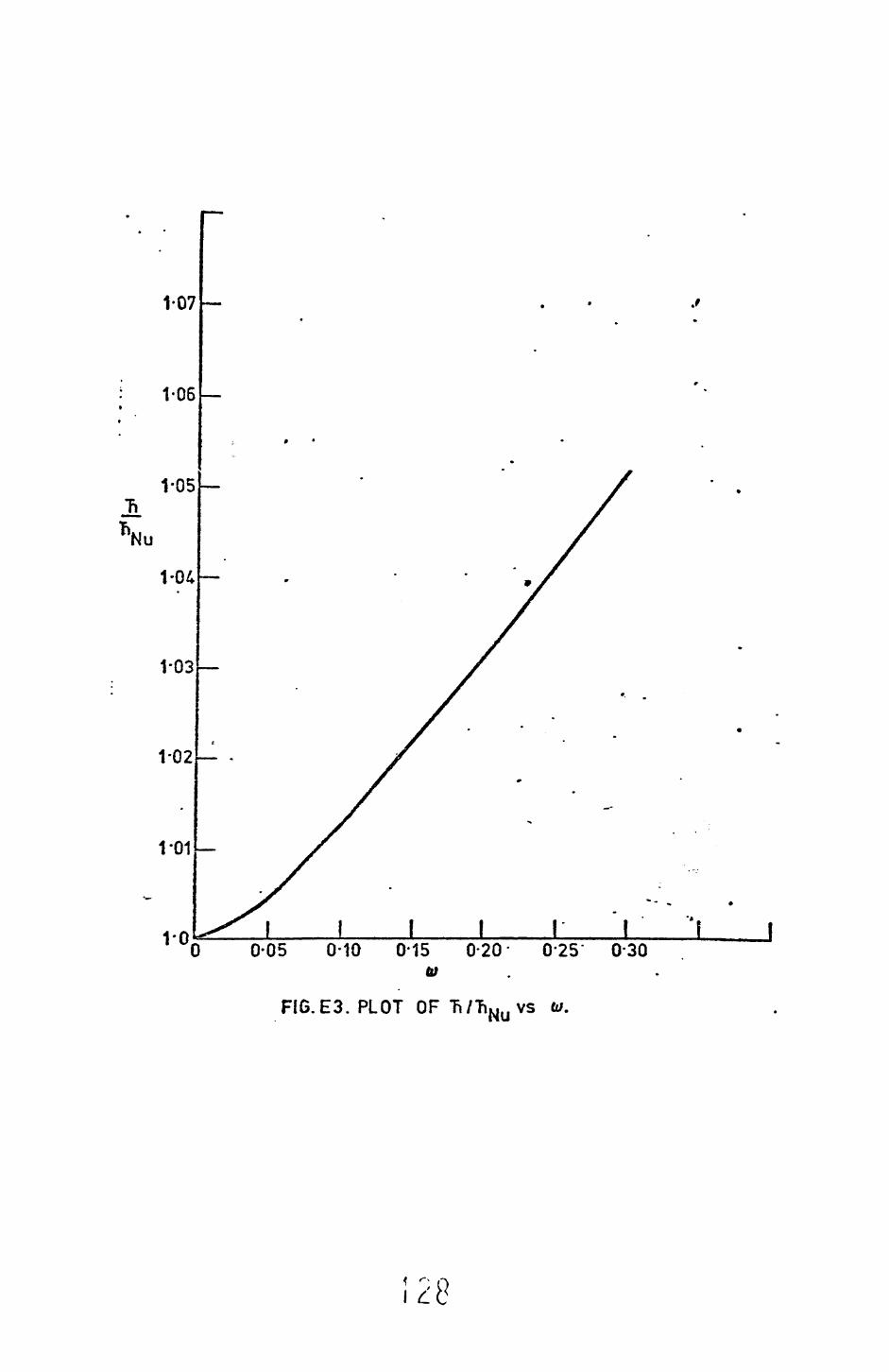
1-07
1-06
0-05 0-10 0-15 0-20 0*25 0'30
FI6.E3. PLOT OF Tt/TiNu vs

APPENDIX F
Experiments on a Vertical Copper Surface
F.I Introduction
At a late stage in the present study it was decided that useful
information on detailed mechanisms might be obtained using a simple flat
plate. The apparatus described below was designed primarily to give such
information and at the same time provide quantitative heat transfer data.
Unfortunately it was only possible to do relatively few commissioning
runs with this apparatus, however, some limited qualitative and quantitative
data have been obtained.
The following sections will give a brief, description of the apparatus
and the results obtained.
F.2 Apparatus and procedure
The flow diagram of the apparatus is shown in Figure Fl; essentially
the ecuicnent consists of -he following items:
1. Boiler - this is sirnply a 2 litre round bottomed flask fitted
with a reflux condenser. The heat required to boil the liquids is
provided by a 2.0 *<W lscnan~le.
2. Test section - this is described in more detail in section
V O •".r . £ . JL.
3. Total condenser - this consists of a coil made up of several
turns of 7 mm bore glass tube in a 75 mm i.d. glass jacket. The cooling
water passes through the coil.
4. Constant temperature bath - this provides the cooling water, at
a controlled temperature, to the test section.
5. Collection vessels - these are simple conical flasks fitted
with ground glass stoppers to accomodate the glass feed lines.
The lines connecting the various items of equipment are of glass
and P.T.F.E. tubing, all of the vapour lines being lagged with fibreglass.
I L
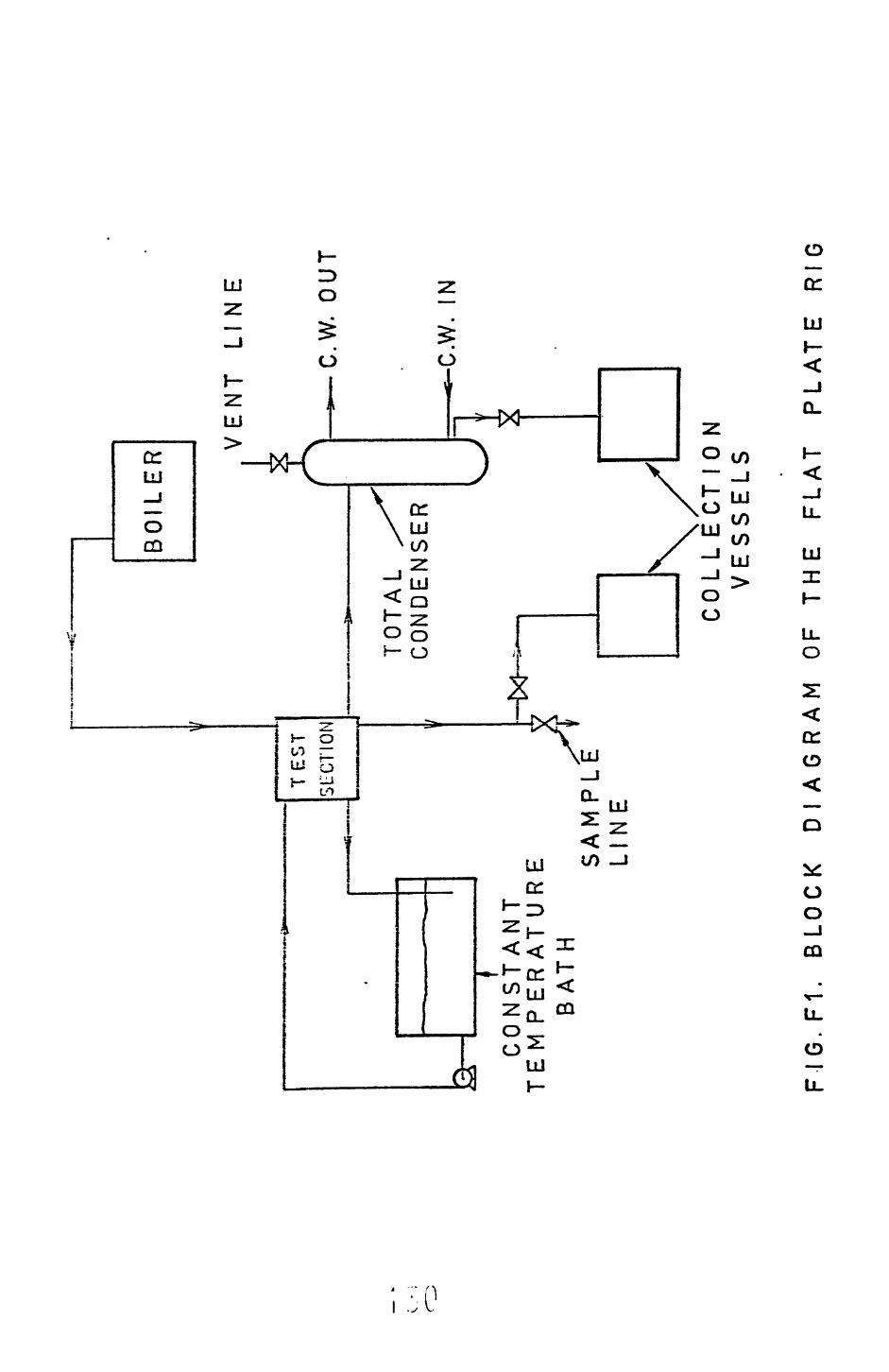
—of
t-
TES
TSU
CTIO
N
1C
ON
ST
AN
T
TE
M P
ER
AT
UR
EB
AT
HS
AM
PL
EL
INE
BO
ILE
R
TO
TA
L C
ON
DE
NS
ER
VE
NT
LI
N E
*-C
.W.
OU
T
-*-C
.W.
IN
CO
LL
EC
T1
0 N
V
ES
SE
LS
FIG
.F1
. B
LOC
K
DIA
GR
AM
O
F T
HE
F
LA
T
PL
AT
E
RIG

F-2.1 Test section
Figure F2 shows the details of the test section, essentially this
is a 90 x 60 x 50 mm copper block. The temperature distribution through
the block is measured by four equally spaced stainless steel sheathed
copper constant an thermocouples. The measuring junctions are located on the
centre line of the block as shown in figure F2. These thermocouples
were calibrated in situ by simply placing the block in a constant temperature,
bath, the bath temperature being determined by a National Physical Laboratory
tested mercury in glass thermometer. The accuracy of calibration was
estimated to be within +_ 0.1°C.
The condensing surface can be viewed through a glass window, when
running the apparatus this window was kept clear of condensate by shining
a 500 W lamp onto the glass, this also provided the illumination for
viewing.
F.2.2 Procedure
Before taking any readings the condensing face of the copper block
was polished with successively finer grades of emery paper until uniformly
smooth. It was ther. vasr.ec with acetone and distilled water before installation,
To commission ~he apparatus the procedure was as follows:
1. The cooling water supplies to the reflux and total condenser*
were turned on.
2. The cooling water to the block was turned on and the temperature
adjusted to the required value.
3. The mixture to be boiled was placed in the boiler and the iso-
mantle switched on.
4. When the system had reached steady state, that is when the
block thermocuples were giving a constant output the following readings
were taken:
1. Thermocouple readings
I J
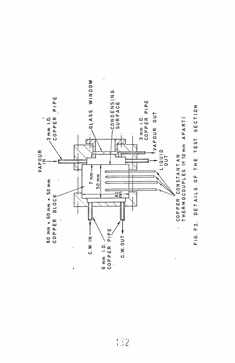
80
mm
x
60 m
m
x 50
mm
C
OP
PE
R
BLO
CK
VA
PO
UR
s|
C.W
. IN
6m
m
I.D.
CO
PP
ER
P
IPE
C.W
. O
UT
—
3 m
m
I.D.
CO
PP
ER
P
IPE
GLA
SS
W
IND
OW
CO
N D
EN
S I
N G
S
UR
FA
CE
'
3 m
m
I.D.
CO
PP
ER
P
I P
E
VA
PO
UR
O
UT
LIQ
UID
O
UT
CO
PP
ER
C
ON
ST
AN
TA
N
TH
ER
MO
CO
UP
LE
S
(^ 1
0 m
m
AP
AR
T)
FIG
. F
2.
DE
TA
ILS
O
F T
HE
T
ES
T
SE
CT
ION
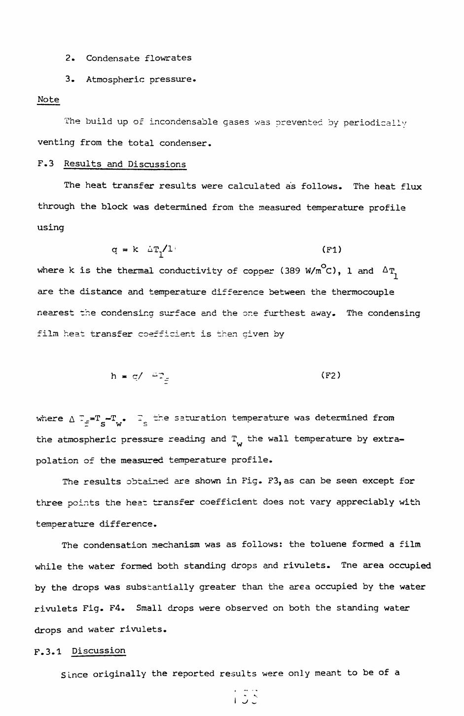
2. Condensate flowrates
3. Atmospheric pressure.
Note
The build up of incondensable gases was prevented by periodical!'/
venting from the total condenser.
F.3 Results and Discussions
The heat transfer results were calculated as follows. The heat flux
through the block was determined from the measured temperature profile
using
q = k AT^/1' (Fl)
where k is the thermal conductivity of copper (389 W/m C), 1 and AT
are the distance and temperature difference between the thermocouple
nearest the condensing surface and the one furthest away. The condensing
film heat transfer coefficient is then given by
h « q/ -T_ (F2)
where A T =T — T . I tr.e saturation temnerature was determined from r s w s
the atmospheric pressure reading and T the wall temperature by extra-"" ri
polation of the measured temperature profile.
The results obtained are shown in Fig. F3, as can be seen except for
three points the heat transfer coefficient does not vary appreciably with
temperature difference.
The condensation mechanism was as follows: the toluene formed a film
while the water formed both standing drops and rivulets. Tne area occupied
by the drops was substantially greater than the area occupied by the water
rivulets Fig. F4. Small drops were observed on both the standing water
drops and water rivulets.
F.3.1 Discussion
Since originally the reported results were only meant to be of a
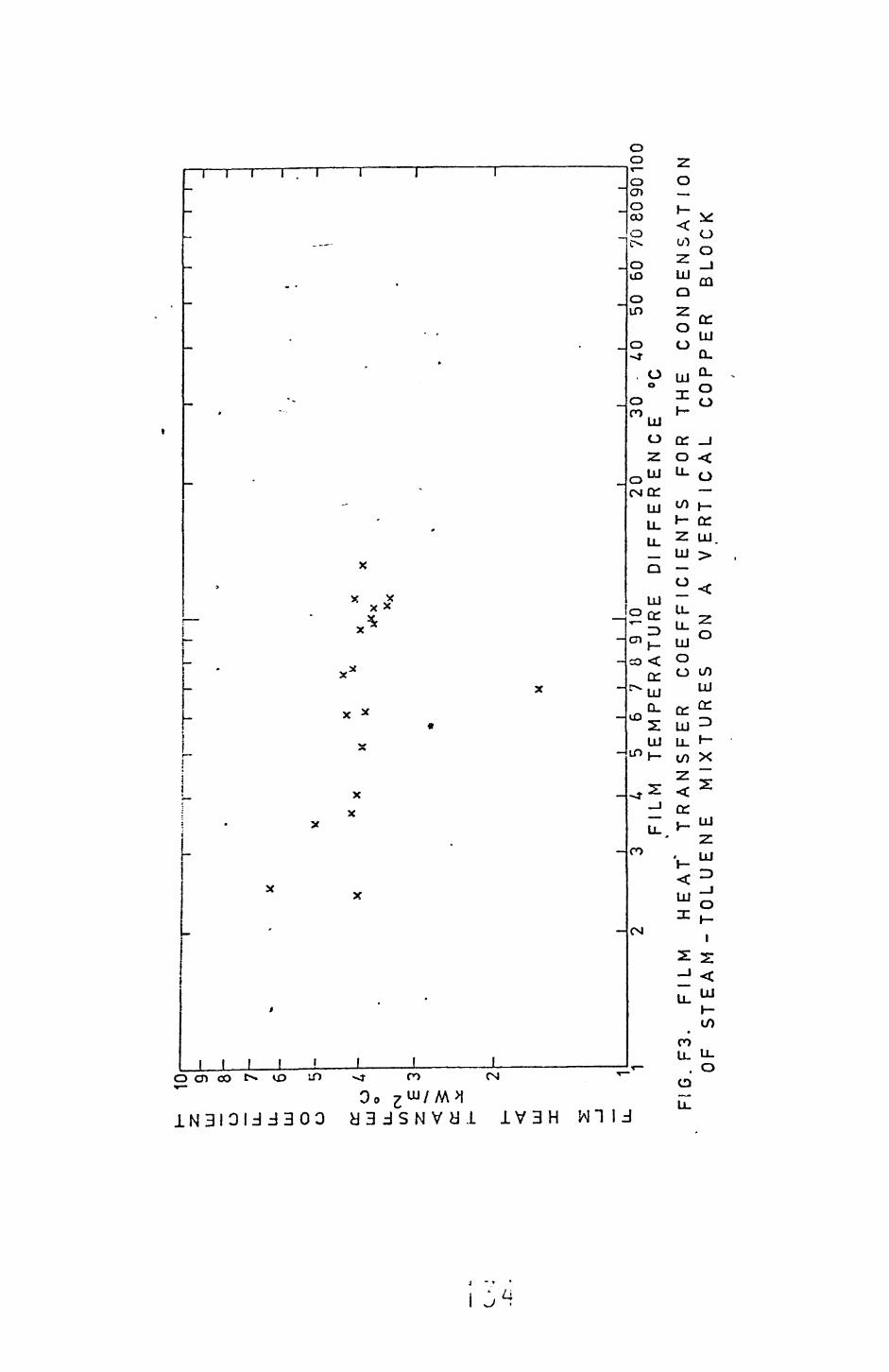
H
102
9LU
3
O
8
u_
7^
£UJ
6
0
t;O
3
ce.
uio
10(N£
3
o: uj LL1
XX X
f._.
i i
r I
i r
X
I I
IU
5 6
7 8
9 10
F
ILM
T
EM
PE
RA
TU
RE
D
l20
30
F
FE
RE
NC
E50
60
70
809
0100
FIG
.F3.
FIL
M
HE
AT
" T
RA
NS
FE
R
CO
EF
FIC
IEN
TS
F
OR
T
HE
C
ON
DE
NS
AT
ION
O
F S
TE
AM
- T
OL
UE
NE
M
IXT
UR
ES
O
N
A V
ER
TIC
AL
C
OP
PE
R
BLO
CK

FIG. F4 FLOW PATTERN for the CONDENSATION of STEAM-TOLUENE MIXTURES ON A VERTICAL FLAT
PLATE
4 *7
preliminary nature (i.e. commissioning runs) no atter.pt v;?s made to
uniformly o::.ldise the copper coneensing surface before use. Thus
the results have been obtained on a surface vjhich has been changina v;ith
time.
- 136 -
APPENDIX G
Error Analysis
•The film heat transfer coefficient is calcralated using the ecu=ii::r_
where m is the rate of condensation, \ the latent heat of vapourisa
A the heat transfer area and AT the film temperature difference.
The estimated accuracy in measuring the above variables is as
follows:
Error on A - this value is assumed correct
Error on X - the physical property correlations are accurate
£ 1.0%.
Error on m - the measurement of the rate of condensation is
estimated to be accurate to v/ithin j-^ 4.C~.
Error on ^ T,. - -his variable is ceierr±ned front the expression/-^ =
T -TL. sr.d since T_ =r.d Hear, be measured tc within jr 0.2 C the error inS ,'( o ,\
- T£ Ls ^_ C.4°C. Thus if _ T^. = 4.0°C the error is jh 10,:%
= 4C.C DC the error is or.lv + 1.0%.-* ^MV
Frcn the above esrlnates of the errors it is apparent that the
minimum theoretical errors in measuring zhe heat transfer coefficient 5_re
+ 15. C% if ^T = 4.C°C and jf 6.0% when T^ = 40.0°C. Thus for the pr^s-ent•"^ TJ" ^"^ i
neasurenents an accuracy limit of _+ 15.0% en the heat transfer dat.a i^
reasonable.
T::e heat balance is determined from the expression
where Q is the heat gained by the cooling water and C)-,.^ is theCW
heat lost by the condensate.
The condensate heat load is determined from Q- = m X . Thus frccn
the above discussion it is aoparent that Q^^>TT. can be measured tov_UIMiJ
•f 5.0%.
The cooling v/ater heat load is obtained from C2 = F At C .cw p

estimated maximum error in measuring F is _+_ 5.0%, v.T.ile the correlation
for determining C is better than _+ l.G:i. Again ih= error in determining
A t depends on its magnitude, the absolute error is _+ 0.05 C.
From the above it is apparent that if t = C.5 JC the error in measuring
the heat balance will be ± 21.0% (5.0 + 1,C + 1C." - 5,0) and if t = 1,0°
the error is +_ 17.0% (5.0 + 1.0 x 5.0 + 5.0).
The limit set on the rejection of data because of bad heat balances
was set at _+_ 15.0%, and the cooling water temperature difference maintained
above 0.5 C were possible.
158