the clic decelerator instrumentation issues – a first look e. adli, cern ab/abp / uio october 17,...
TRANSCRIPT

The CLIC decelerator The CLIC decelerator Instrumentation issues – a first lookInstrumentation issues – a first look
E. Adli, CERN AB/ABP / UiOE. Adli, CERN AB/ABP / UiO
October 17, 2007October 17, 2007
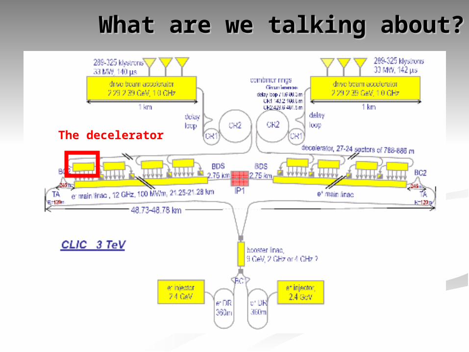
What are we talking about?What are we talking about?
The decelerator

ContentContent
Particularities of the decelerator beamParticularities of the decelerator beam
Instrumentation discussionInstrumentation discussion
Comparison with the TBLComparison with the TBL
Goal of presentation: convey beam dynamics of the drive beam decelerator, then discuss (in plenum) the instrumentation issues
Part 1Part 1
Particularities of the decelerator beamParticularities of the decelerator beam
Decelerator BD requirementsDecelerator BD requirements
Deliver required power to accelerating structuresDeliver required power to accelerating structures Minimize losses ( smaller than 0.1% )Minimize losses ( smaller than 0.1% )
High power production efficiencyHigh power production efficiency Low final energy Low final energy large energy spread large energy spread
Our target is to transport the beam, the Our target is to transport the beam, the whole whole beambeam, through the decelerator lattice, through the decelerator lattice

The decelerator latticeThe decelerator lattice
(parameters of mid-2007)(parameters of mid-2007) 26 * 2 stations26 * 2 stations 688 units per station688 units per station
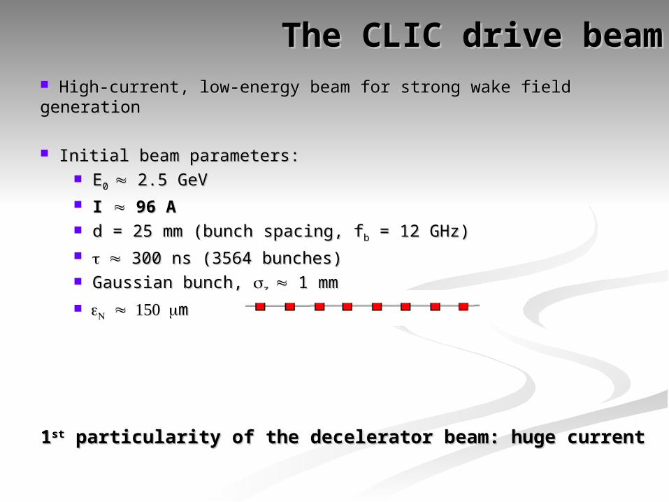
The CLIC drive beamThe CLIC drive beam High-current, low-energy beam for strong wake field generationHigh-current, low-energy beam for strong wake field generation
Initial beam parameters:Initial beam parameters: EE0 0 2.5 GeV 2.5 GeV I I 96 A 96 A d = 25 mm (bunch spacing, fd = 25 mm (bunch spacing, fbb = 12 GHz) = 12 GHz) 300 ns (3564 bunches) 300 ns (3564 bunches) Gaussian bunch, Gaussian bunch, z z 1 mm 1 mm
m m
11stst particularity of the decelerator beam: huge current particularity of the decelerator beam: huge current

Principle of power generationPrinciple of power generation Particles will feel parasitic loss and induce a wake field in Particles will feel parasitic loss and induce a wake field in
the PETSthe PETS The wake field will interact with and further decelerate :The wake field will interact with and further decelerate :
1) rear part of bunch (1) rear part of bunch (single-bunchsingle-bunch effect) effect)
2) following bunches (2) following bunches (multi-bunchmulti-bunch effect) effect)
The integrated effect in a PETS on a witness particle due The integrated effect in a PETS on a witness particle due to a source particle is given byto a source particle is given by

Simulation results: energy extractionSimulation results: energy extraction
PETS longitudinal wake parameters:PETS longitudinal wake parameters: R’/Q = 2295 R’/Q = 2295 /m (linac-convention)/m (linac-convention) ffLL=11.99 GHz=11.99 GHz gg = 0.453 = 0.453
Beam energy profile after lattice: Beam energy profile after lattice: (initial: flat E(initial: flat E00=2.5 GeV)=2.5 GeV)
22ndnd particularity of the decelerator: huge energy spread particularity of the decelerator: huge energy spread
NB: leading particle always to the left! (PLACET output def.)NB: leading particle always to the left! (PLACET output def.)

Energy extraction efficiency: Energy extraction efficiency: PPinin/P/Poutout : : steady statesteady state power extraction eff.: power extraction eff.: P[W]P[W]N / N /
E0[eV]E0[eV]I[A] I[A]
We can express the We can express the steady statesteady state extraction efficiency as: extraction efficiency as:= S = S F( F() ) distdist
where for current CLIC parameters:where for current CLIC parameters: S = 90.0 % (max energy spread)S = 90.0 % (max energy spread) = S = S F( F() ) distdist = 90.0 % = 90.0 % 96.9 % 96.9 % 97.4 % = 97.4 % =84.5 %84.5 %
((distdist can be improved with detuning: not discussed further here) can be improved with detuning: not discussed further here)
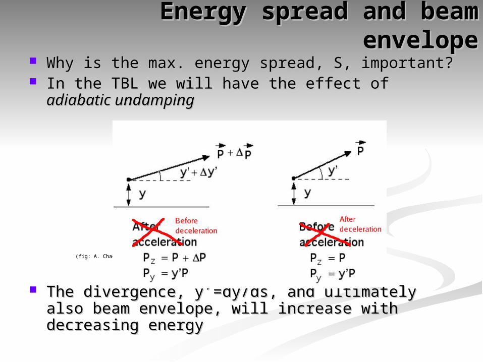
Energy spread and beam envelopeEnergy spread and beam envelope Why is the max. energy spread, S, important?Why is the max. energy spread, S, important? In the TBL we will have the effect of In the TBL we will have the effect of adiabatic undampingadiabatic undamping
(fig: A. Chao)(fig: A. Chao)
The divergence, y’=dy/ds, and ultimately also beam The divergence, y’=dy/ds, and ultimately also beam envelope, will increase with decreasing energyenvelope, will increase with decreasing energy

Beam envelope along the latticeBeam envelope along the lattice
Thus, beam envelope along the lattice rThus, beam envelope along the lattice radad 1/ 1/
02/2222 )1/(2333 SLr NFODOyxad
Beam envelope due to adiabatic undamping aloneBeam envelope due to adiabatic undamping alone

Misalignment: PETSMisalignment: PETS
Misalignment and beam jitter will introduce growth of Misalignment and beam jitter will introduce growth of beam envelope due to transverse wakesbeam envelope due to transverse wakes
Effect on beam envelope for PETS misalignment of 200 Effect on beam envelope for PETS misalignment of 200 um:um:
Adiabatic effects alone
With PETS misalignment

Misalignment: quadsMisalignment: quads
Misalignment of quadruples will introduce growth of beam Misalignment of quadruples will introduce growth of beam envelope due to kicksenvelope due to kicks
Effect on beam envelope for quadrupole misalignment of Effect on beam envelope for quadrupole misalignment of 20 um:20 um:
33rdrd particularity of the decelerator: large beam size particularity of the decelerator: large beam size
Adiabatic effects alone
With quadrupole misalignment
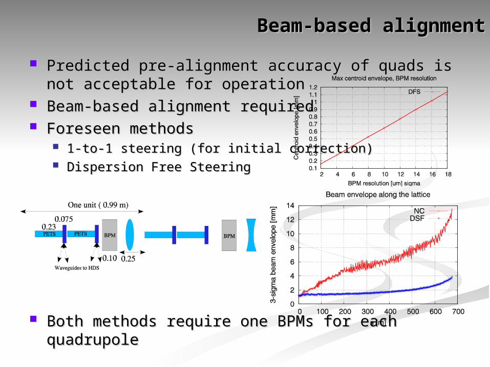
Beam-based alignmentBeam-based alignment
Predicted pre-alignment accuracy of quads is not Predicted pre-alignment accuracy of quads is not acceptable for operationacceptable for operation
Beam-based alignment requiredBeam-based alignment required Foreseen methodsForeseen methods
1-to-1 steering (for initial correction)1-to-1 steering (for initial correction) Dispersion Free SteeringDispersion Free Steering
Both methods require one BPMs for each quadrupoleBoth methods require one BPMs for each quadrupole
Part 2Part 2
Decelerator instrumentation – a first lookDecelerator instrumentation – a first look
BPMsBPMs
The need for beam-based alignment implies:The need for beam-based alignment implies:
One BPM per quadrupoleOne BPM per quadrupole Total number of BPMs: ~ 26 * 2 * 688 = ~ 36000Total number of BPMs: ~ 26 * 2 * 688 = ~ 36000 Current: ~ 100 ACurrent: ~ 100 A BPM resolution requirement derived from dispersion-free BPM resolution requirement derived from dispersion-free
steering: ~10umsteering: ~10um Beam envelope (~99.9%) might reach close to PETS Beam envelope (~99.9%) might reach close to PETS
aperture limit of 11.5 mm. (at start of decelerator aperture limit of 11.5 mm. (at start of decelerator envelope size: ~1 mm)envelope size: ~1 mm) Centroid signal / range of BPM: few millimetersCentroid signal / range of BPM: few millimeters But signal from halo-particles must be taken into accountBut signal from halo-particles must be taken into account
Available length for BPMs: Available length for BPMs: 10 cm 10 cm
(Discussion / input from instrument workgroup here)(Discussion / input from instrument workgroup here)
Beam profile monitors / loss monitorsBeam profile monitors / loss monitors
Requirement: transport with minimal lossesRequirement: transport with minimal losses
Desirable: instrumentation to measure Desirable: instrumentation to measure transverse beam sizetransverse beam size
Desirable: loss monitorsDesirable: loss monitors Installation frequency of these components is TBDInstallation frequency of these components is TBD Keeping instrumentation small is of concern (in the Keeping instrumentation small is of concern (in the
current design: zero length is foreseen for such current design: zero length is foreseen for such instrumentation, except of PETS-free units)instrumentation, except of PETS-free units)
(Discussion / input from instrument workgroup here)(Discussion / input from instrument workgroup here)
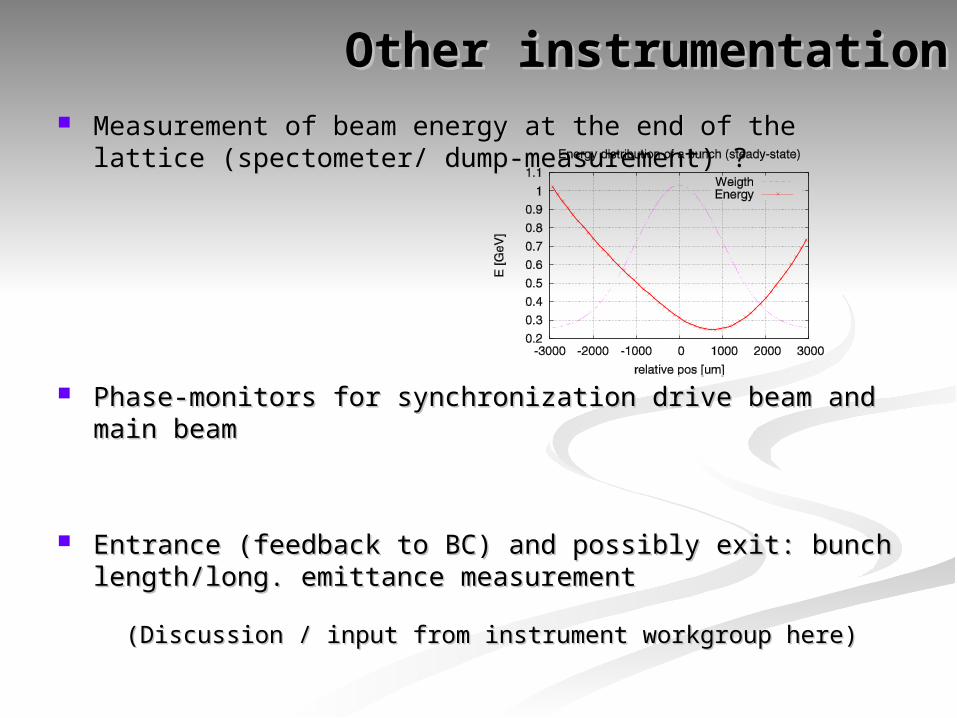
Other instrumentationOther instrumentation Measurement of beam energy at the end of the lattice (spectometer/ Measurement of beam energy at the end of the lattice (spectometer/
dump-measurement) ?dump-measurement) ?
Phase-monitors for synchronization drive beam and main beamPhase-monitors for synchronization drive beam and main beam
Entrance (feedback to BC) and possibly exit: bunch length/long. Entrance (feedback to BC) and possibly exit: bunch length/long. emittance measurementemittance measurement
(Discussion / input from instrument workgroup here)(Discussion / input from instrument workgroup here)
Part 3Part 3
The Test Beam LineThe Test Beam Line
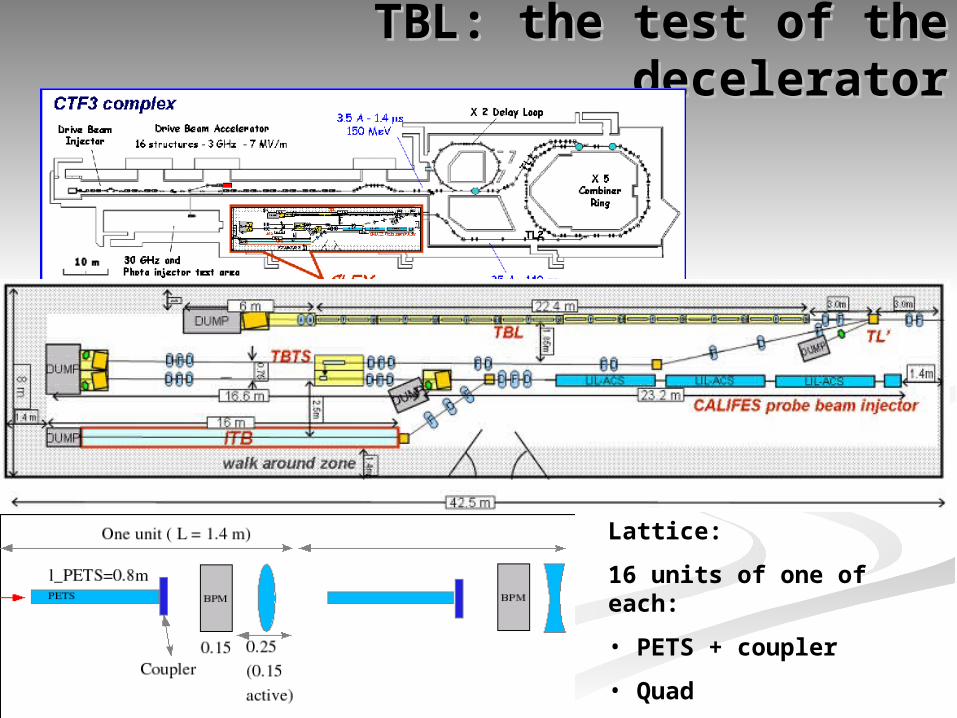
TBL: the test of the deceleratorTBL: the test of the decelerator
Lattice:
16 units of one of each:
• PETS + coupler
• Quad
• BPM

Beam dynamics of TBLBeam dynamics of TBL
However, the TBL will show the same beam dynamics effects as the CLIC decelerator:
* envelope growth
* decelerated energy profile
Different parameter range:
* E0 ~ 150 MeV, I ~ 30 A, ns
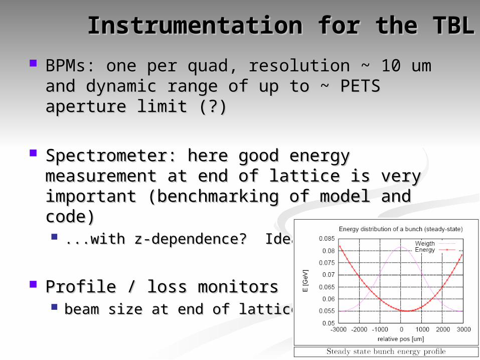
Instrumentation for the TBLInstrumentation for the TBL
BPMs: one per quad, resolution ~ 10 um and BPMs: one per quad, resolution ~ 10 um and dynamic range of up to ~ PETS aperture limit (?)dynamic range of up to ~ PETS aperture limit (?)
Spectrometer: here good energy measurement Spectrometer: here good energy measurement at end of lattice is very important (benchmarking at end of lattice is very important (benchmarking of model and code)of model and code) ...with z-dependence? Ideas?...with z-dependence? Ideas?
Profile / loss monitorsProfile / loss monitors beam size at end of lattice?beam size at end of lattice?