the hypersonic inflatable aerodynamic decelerator (hiad ... · pdf filethe hypersonic...
TRANSCRIPT

American Institute of Aeronautics and Astronautics
1
The Hypersonic Inflatable Aerodynamic Decelerator (HIAD)
Mission Applications Study
David M. Bose1, Richard Winski
2, and Jeremy Shidner
3
Analytical Mechanics Associates, Inc
Hampton, VA 23666
Carlie Zumwalt4
NASA Johnson Space Center
Houston, TX 77058
Christopher O. Johnston5, D.R. Komar
6, F. M. Cheatwood
7, and Stephen J. Hughes
8
NASA Langley Research Center
Hampton, VA 23681
The objective of the HIAD Mission Applications Study is to quantify the benefits of HIAD infusion to the concept
of operations of high priority exploration missions. Results of the study will identify the range of mission concepts
ideally suited to HIADs and provide mission-pull to associated technology development programs while further
advancing operational concepts associated with HIAD technology. A summary of Year 1 modeling and analysis
results is presented covering missions focusing on Earth and Mars-based applications. Recommended HIAD scales
are presented for near term and future mission opportunities and the associated environments (heating and structural
loads) are described.
Nomenclature
ADB Aerodatabase
AIAA American Institute of Aeronautics and Astronautics C C programming language
CEV Crew Exploration Vehicle
CFD Computational Fluid Dynamics CH4 Liquid Methane
DGB Disk-Gap-Band
EDL Entry, Descent, and Landing EDL-SA Entry, Descent, and Landing Systems Analysis
EFPA Entry Flight Path Angle EXAMINE Exploration Architecture Model for IN-space and
Earth-to-orbit
FPA Flight Path Angle FSD Flexible Systems Development
GRAM Global Reference Atmospheric Model
HARA High-temperature Aerothermodynamic RAdiation HEART High-Energy Atmospheric Reentry Test
HIAD Hypersonic Inflatable Aerodynamic Decelerator
IEEE Institute of Electrical and Electronics Engineers IRVE Inflatable Reentry Vehicle Experiment
L/D Lift to Drag Ratio
L2 Earth-moon Lagrange Point 2
LAURA Langley Aerothermodynamic Upwind Relaxation Algorithm
LEO Low Earth Orbit
LFE Lander Functional Element LO2 Liquid Oxygen
MLI Multi-Layer Insulation
MMH Monomethylhydrazine MOLA Mars Orbiter Laser Altimeter
MPCV Multi-Purpose Crew Vehicle MSC Marshal Spaceflight Center
MSL Mars Science Laboratory
NASA National Aeronautics and Space Administration NTO Nitrogen Tetroxide
Orion The NASA Crew Exploration Vehicle Development
Program POST2 Program to Optimize Simulated Trajectories II
RCS Reaction Control System
SRP Supersonic Retro-Propulsion TPS Thermal Protection System
1. Vice President, Modeling and Simulation, 5500 Democracy Drive, Suite 110, Plano, TX, AIAA Senior Member
2. Engineer IV, Dynamics and Controls, 303 Butler Farm Road, Suite 104A, Hampton, VA, AIAA Senior Member
3. Supervising Engineer, Dynamics and Controls, 303 Butler Farm Road, Suite 104A, Hampton, VA, AIAA Senior
Member
4. Aerospace Engineer, Flight Mechanics and Trajectory Design Branch, Mail Stop EG5
5. Aerospace Engineer, Aerothermodynamics Branch, Mail Stop 408A, AIAA Member
6. Senior Aerospace Engineer, Vehicle Analysis Branch, Mail Stop E401
7. EDL Principle Investigator, Space Technology Mission Directorate, Mail Stop 250, AIAA Associate Fellow
8. HIAD Chief Engineer, Mechanical Systems Branch, Mail Stop 432, AIAA Member
https://ntrs.nasa.gov/search.jsp?R=20130013397 2018-05-14T20:57:24+00:00Z

American Institute of Aeronautics and Astronautics
2
I. Introduction
The successful flights of the Inflatable Reentry Vehicle Experiment (IRVE)-2 and IRVE-3 projects have
demonstrated the potential value of Hypersonic Inflatable Aerodynamic Decelerator (HIAD) technology. The
development of this technology is currently pursued by the HIAD Project, funded by NASA’s Office of Chief
Technologist’s Game Changing Program. The HIAD Project is divided into three areas, namely Flexible Systems
Development (FSD), Flight Validation, and Advanced Entry Concepts. FSD has two elements including a Flexible
Thermal Protection System (TPS) element and an Inflatable Structures element. The Advanced Entry Concepts
effort is divided into Mission Applications and Next Generation Subsystems. Next Generation Subsystems is
investigating methods for generating lift on blunted cones focusing on aerodynamic trim surfaces. Mission
Applications is evaluating and developing concepts (including payload interfaces) for missions at multiple
destinations for the purpose of demonstrating the benefits and need for HIAD technology. Providing a summary of
concepts evaluated in Year 1 of HIAD Mission Application trade studies is the purpose of this paper. A more
complete overview of the HIAD project is provided by Hughes et al.1
A. HIAD Mission Applications Overview
The objective of HIAD Mission Applications is to identify the improvements associated with HIAD integration
within the concept of operations of high priority missions. Potential improvements may come in the form of
performance, cost, or risk measures in all phases of the mission from spacecraft and launch vehicle integration
through entry descent and landing (EDL). Some specific examples of potential improvements include:
Reduced launch costs: can mass and/or packaging advantages of a HIAD allow for launch on smaller class
of launch vehicle?
Enhanced Integration: does HIAD packaging provide improved access to the payload and spacecraft
subsystems during integration?
Increased performance margins: does the increased deceleration of the HIAD allow for longer mission
time between significant EDL events? Does a HIAD allow for a steeper entry angle, resulting in a smaller
landing footprint?
Expanded mission potential and science return: does HIAD integration lead to the ability to deliver
more payload to the surface of the target destination and provide accessibility to higher altitude landing
sites?
In order to uncover these benefits it is necessary to develop a full-systems view of HIAD integration. Performing
this level of design and analysis is also an objective of HIAD Mission Applications. In addition, the development of
results which can help to uncover system sensitivities, address what-if scenarios, and help guide future investments
is a significant project goal. This includes, for example, understanding which secondary deceleration devices
(supersonic parachute, subsonic parachute, supersonic aerodynamic decelerator, retro-propulsion) and landing
systems (legs, air bags, crushable materials) make the most sense to couple with the HIAD for a given reference
mission.
B. HIAD Mission Applications Approach and Scope
In order to address the objectives of HIAD Mission Applications, a work plan was crafted that calls for iterative
modeling and analysis cycles with two levels of fidelity. The first is a conceptual level, characterized by trade
studies aimed at identifying the required HIAD scale for missions of interest over a broad range of entry conditions.
Typical trade parameters include entry flight path angle (EFPA), entry velocity, entry mass, and HIAD diameter. In
a given analysis run, iteration on HIAD mass is required to ensure the mass-scaling of the HIAD is commensurate
with the heat load and dynamic pressure associated with the flight trajectory. Once the trade is complete,
recommended HIAD scale can be evaluated through application of system constraints (e.g. heat rate limits) to
identify regions of feasibility. From the region of feasibility, design points are selected based on mission
improvement objectives. The second level of fidelity provides deeper modeling and analysis activities into specific
design points within the trade space. This “deep dive” roots out significant system drivers and develops a comp lete
systems view of the design.

American Institute of Aeronautics and Astronautics
3
In Year 1 of HIAD Mission Applications, conceptual level trades were performed in the following areas. Selection
of design points and “deep-dive” design and analysis is part of the Year 2 plan.
Hybrid Lunar Return: evaluation of a HIAD in returning the Multi-Purpose Crew Vehicle (MPCV) from
a lunar mission via direct Earth entry. This is considered a hybrid since the HIAD is used to augment the
existing MPCV heat shield.
Hybrid Mars Return: evaluation of a HIAD in returning MPCV from a Mars mission via direct Earth
entry.
Launch Asset Recovery: evaluation of a HIAD in the recovery of launch vehicle assets. This particular
study focuses on 1st and 2
nd stage recovery.
L2 to LEO Transfer: evaluation of a HIAD in the transfer of the MPCV from an L2 Earth-Moon
Lagrange point (L2) to a Low Earth Orbit (LEO) orbit through aerocapture.
Mars Fast Transit: evaluation of a HIAD in the transfer of MPCV to low or high Earth orbits in a Mars
fast transit scenario.
Mars Aerocapture: evaluation of a HIAD in performing aerocapture at Mars.
Mars Southern Highlands: evaluation of a HIAD in performing direct-entry at Mars with access to higher
altitudes such as those associated with the Mars Southern Highlands region.
II. Modeling
A. Reference Vehicles
Two reference entry vehicles were employed in the studies conducted in Year 1. This includes a hybrid vehicle
comprised of a HIAD affixed to the MPCV. The second is a standard 60 deg. sphere cone. High level attributes of
these vehicles are described here. Mission specific vehicle attributes are called out in each study summarized in
Section III. HIAD diameter, entry mass, entry velocity, and EFPA vary by application.
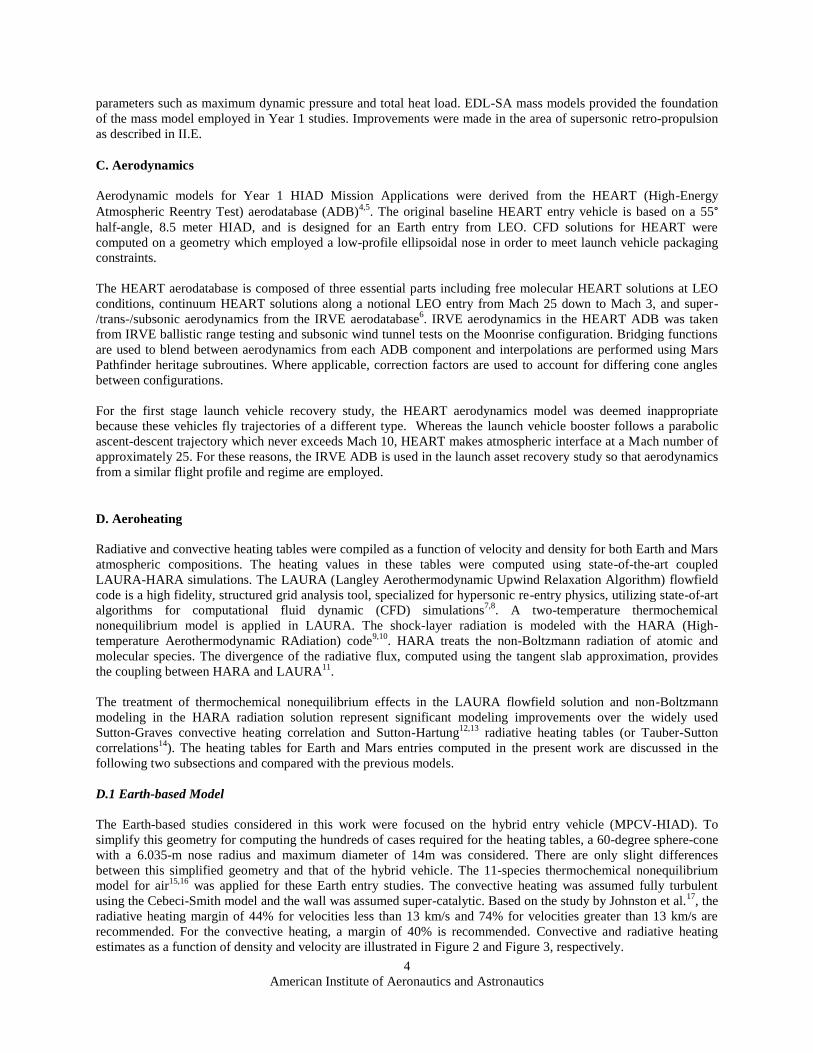
The “hybrid” reference vehicle combines a 60-degree HIAD with the MPCV. An artist’s rendition of this concept is
illustrated in Figure 1. The slope of the MPCV at the shoulder of the heat shield is roughly 67-degrees. As a result, a
slope discontinuity exists between the heat shield and the HIAD. The impact of this is seen in aeroheating analysis,
which predicts higher localized heating in the region of this discontinuity. It is assumed that detailed design of the
MPCV/HIAD interface can mitigate these effects.
Hybrid Reference Vehicle
MPCV Diameter [m]: 5.0
Nose Radius [m]: 6.0
HIAD ½ Cone Angle [deg]: 60
Standard Vehicle
Nose Radius [m]: 4.0
HIAD ½ Cone Angle [deg]: 60 deg.
Figure 1. The hybrid reference vehicle.
B. Mass Model
Mass modeling of entry systems investigated in the studies summarized in Section III followed the Entry Descent
and Landing Systems Analysis project (EDL-SA) approach2,3
, which provides a parametric mass model that
mathematically represents mass components as a function of vehicle dimensions and key mission environmental
American Institute of Aeronautics and Astronautics
4
parameters such as maximum dynamic pressure and total heat load. EDL-SA mass models provided the foundation
of the mass model employed in Year 1 studies. Improvements were made in the area of supersonic retro-propulsion
as described in II.E.
C. Aerodynamics
Aerodynamic models for Year 1 HIAD Mission Applications were derived from the HEART (High-Energy
Atmospheric Reentry Test) aerodatabase (ADB)4,5
. The original baseline HEART entry vehicle is based on a 55° half-angle, 8.5 meter HIAD, and is designed for an Earth entry from LEO. CFD solutions for HEART were
computed on a geometry which employed a low-profile ellipsoidal nose in order to meet launch vehicle packaging
constraints.
The HEART aerodatabase is composed of three essential parts including free molecular HEART solutions at LEO
conditions, continuum HEART solutions along a notional LEO entry from Mach 25 down to Mach 3, and super-
/trans-/subsonic aerodynamics from the IRVE aerodatabase6. IRVE aerodynamics in the HEART ADB was taken
from IRVE ballistic range testing and subsonic wind tunnel tests on the Moonrise configuration. Bridging functions
are used to blend between aerodynamics from each ADB component and interpolations are performed using Mars
Pathfinder heritage subroutines. Where applicable, correction factors are used to account for differing cone angles
between configurations.
For the first stage launch vehicle recovery study, the HEART aerodynamics model was deemed inappropriate
because these vehicles fly trajectories of a different type. Whereas the launch vehicle booster follows a parabolic
ascent-descent trajectory which never exceeds Mach 10, HEART makes atmospheric interface at a Mach number of
approximately 25. For these reasons, the IRVE ADB is used in the launch asset recovery study so that aerodynamics
from a similar flight profile and regime are employed.
D. Aeroheating
Radiative and convective heating tables were compiled as a function of velocity and density for both Earth and Mars
atmospheric compositions. The heating values in these tables were computed using state-of-the-art coupled
LAURA-HARA simulations. The LAURA (Langley Aerothermodynamic Upwind Relaxation Algorithm) flowfield
code is a high fidelity, structured grid analysis tool, specialized for hypersonic re-entry physics, utilizing state-of-art
algorithms for computational fluid dynamic (CFD) simulations7,8
. A two-temperature thermochemical
nonequilibrium model is applied in LAURA. The shock-layer radiation is modeled with the HARA (High-
temperature Aerothermodynamic RAdiation) code9,10
. HARA treats the non-Boltzmann radiation of atomic and
molecular species. The divergence of the radiative flux, computed using the tangent slab approximation, provides
the coupling between HARA and LAURA11
.
The treatment of thermochemical nonequilibrium effects in the LAURA flowfield solution and non-Boltzmann
modeling in the HARA radiation solution represent significant modeling improvements over the widely used
Sutton-Graves convective heating correlation and Sutton-Hartung12,13
radiative heating tables (or Tauber-Sutton
correlations14
). The heating tables for Earth and Mars entries computed in the present work are discussed in the
following two subsections and compared with the previous models.
D.1 Earth-based Model
The Earth-based studies considered in this work were focused on the hybrid entry vehicle (MPCV-HIAD). To
simplify this geometry for computing the hundreds of cases required for the heating tables, a 60-degree sphere-cone
with a 6.035-m nose radius and maximum diameter of 14m was considered. There are only slight differences
between this simplified geometry and that of the hybrid vehicle. The 11-species thermochemical nonequilibrium
model for air15,16
was applied for these Earth entry studies. The convective heating was assumed fully turbulent
using the Cebeci-Smith model and the wall was assumed super-catalytic. Based on the study by Johnston et al.17
, the
radiative heating margin of 44% for velocities less than 13 km/s and 74% for velocities greater than 13 km/s are
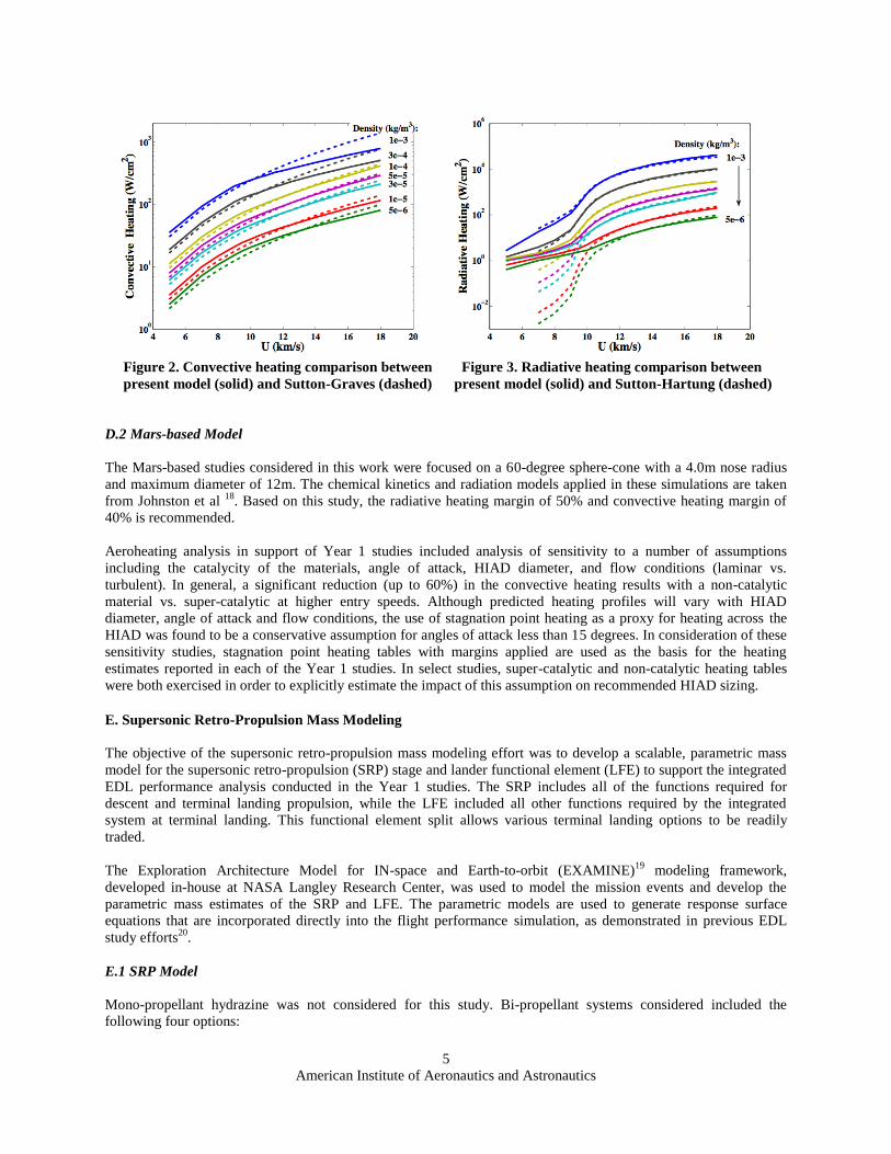
recommended. For the convective heating, a margin of 40% is recommended. Convective and radiative heating
estimates as a function of density and velocity are illustrated in Figure 2 and Figure 3, respectively.
American Institute of Aeronautics and Astronautics
5
Figure 2. Convective heating comparison between Figure 3. Radiative heating comparison between
present model (solid) and Sutton-Graves (dashed) present model (solid) and Sutton-Hartung (dashed)
D.2 Mars-based Model
The Mars-based studies considered in this work were focused on a 60-degree sphere-cone with a 4.0m nose radius
and maximum diameter of 12m. The chemical kinetics and radiation models applied in these simulations are taken
from Johnston et al 18
. Based on this study, the radiative heating margin of 50% and convective heating margin of
40% is recommended.
Aeroheating analysis in support of Year 1 studies included analysis of sensitivity to a number of assumptions
including the catalycity of the materials, angle of attack, HIAD diameter, and flow conditions (laminar vs.
turbulent). In general, a significant reduction (up to 60%) in the convective heating results with a non-catalytic
material vs. super-catalytic at higher entry speeds. Although predicted heating profiles will vary with HIAD
diameter, angle of attack and flow conditions, the use of stagnation point heating as a proxy for heating across the
HIAD was found to be a conservative assumption for angles of attack less than 15 degrees. In consideration of these
sensitivity studies, stagnation point heating tables with margins applied are used as the basis for the heating
estimates reported in each of the Year 1 studies. In select studies, super-catalytic and non-catalytic heating tables
were both exercised in order to explicitly estimate the impact of this assumption on recommended HIAD sizing.
E. Supersonic Retro-Propulsion Mass Modeling
The objective of the supersonic retro-propulsion mass modeling effort was to develop a scalable, parametric mass
model for the supersonic retro-propulsion (SRP) stage and lander functional element (LFE) to support the integrated
EDL performance analysis conducted in the Year 1 studies. The SRP includes all of the functions required for
descent and terminal landing propulsion, while the LFE included all other functions required by the integrated
system at terminal landing. This functional element split allows various terminal landing options to be readily
traded.
The Exploration Architecture Model for IN-space and Earth-to-orbit (EXAMINE)19
modeling framework,
developed in-house at NASA Langley Research Center, was used to model the mission events and develop the
parametric mass estimates of the SRP and LFE. The parametric models are used to generate response surface
equations that are incorporated directly into the flight performance simulation, as demonstrated in previous EDL
study efforts20
.
E.1 SRP Model
Mono-propellant hydrazine was not considered for this study. Bi-propellant systems considered included the
following four options:

American Institute of Aeronautics and Astronautics
6
1. Pump-fed engine burning nitrogen tetroxide (NTO) and monomethylhydrazine (MMH)
2. Pressure-fed engine burning NTO and MMH
3. Pump-fed engine burning liquid oxygen (LO2) and liquid methane (CH4)
4. Pressure-fed engine burning LO2 and CH4
The primary SRP stage structure is modeled as a 2.6 m diameter aluminum-lithium cylinder that supports the tank
system and payload. This primary structure mass is estimated from a historically-based empirical curve fit 21
. Thrust
structure mass is based on a historical fit accounting for stage diameter, the number of engines and the thrust load.
Secondary structure mass is 5% of the primary plus thrust structure masses.
The reaction control system (RCS) has sixteen pressure-fed thrusters each producing a thrust of 100 lbf. Each
thruster operates at a chamber pressure of 125 psia, a mixture ratio of 1.65, and an area ratio of 40 delivering an Isp
of 301.3 sec. The RCS propellants are stored at 225 psia in two spherical graphite-wrapped aluminum tanks, one for
NTO and one for MMH. Tank heaters and 10 layers of multi-layer insulation (MLI) provide thermal control for the
tanks during interplanetary coast while a 6,000 psia gaseous helium tank, constructed of graphite-wrapped
aluminum, provides consumables for RCS tank pressurization.
Thermal control for SRP vehicle systems includes MLI, heaters and a heat pipe heat rejection system. The mass
estimate for the SRP thermal control system is derived from the Mars Science Laboratory project (MSL). In
addition, mass estimate for cabling, instrumentation and stage separation pyro-bolt mechanisms were derived from
MSL.
Ground rules of the EDL Feed Forward study, conducted under EDL-SA, required a total mass margin of 49.5% of
the basic dry mass which includes allocations for both mass growth allowance and project manager’s reserve.
E.2 Lander Functional Element
The LFE mass model includes the common and dedicated functional subsystems for the various landing mode trade
options considered. For common function subsystems, mass estimates are derived directly from MSL. For the
optional subsystems, a basic parametric approach was utilized initially while more detailed models are developed.
Landing leg and airbag system masses are determined parametrically as a function of landed mass. Typical values
for landing legs range from 2-5% of the landed mass, although small robotic-class landers using landing legs could
potentially have a higher landing leg fraction22
. For landing airbags, a range of 1-5% is typical. As a point of
reference, a land landing study for the Orion capsule was performed and the resulting landing airbag fraction was
approximately 2.5% 23
. For robotic-class missions with smaller landed mass the airbag fraction could be a higher
fraction of the mass.
F. Flexible Thermal Protection System
Advances in flexible TPS are being pursued though the Flexible Systems Development element of the HIAD
Project. This includes a detailed test program for material layups as well as the development and calibration of a
high fidelity thermal model for predicting TPS performance in a real mission configuration and environment.
Application of this high fidelity model will be performed as part of the deep dive design and analysis activity
planned under Year 2 of HIAD Mission Applications. In Year 1, however, consideration for flexible TPS is made in
the application of TPS performance limits as constraints to trade study results. At the current time, these limits are
based on the performance targets of the Flexible Systems Development element. These targets include:
1st Generation Flexible TPS, targeting a 5-meter HIAD: 20 W/cm^2
1st Generation Flexible TPS, targeting a 10-meter HIAD: 30 W/cm^2
2nd
Generation Flexible TPS, targeting a 10-meter HIAD: 50 W/cm^2
3rd
Generation Flexible TPS, targeting a 10-meter HIAD: 75 W/cm^2

American Institute of Aeronautics and Astronautics
7
G. Simulation Development
In order to simulate a broad range of potential HIAD applications, a simulation framework was needed that would
work across multiple planets and mission scenarios. The Program to Optimize Simulated Trajectories II (POST2)
was selected as the primary simulation tool. The latest version 3.0 was upgraded as needed in the HIAD Mission
Applications study. The benefits of using this latest version include the program being written in C, stability of the
code base, and improved source code control. An additional benefit that POST2 offers is a diverse selection of
atmosphere models. All of the Marshall atmosphere models, denoted GRAM (Global Reference Atmospheric
Model), have been incorporated and checked out in POST2. This provides a baseline atmosphere to use for multiple
planets including Earth, Mars, Venus, Titan and more.
III. Year 1 Trade Studies
Studies performed in support of Year 1 HIAD Mission Applications activities are summarized in this section.
A. Hybrid Lunar and Mars Return Studies
Return from lunar orbit must deal with higher
energy entries than that from typical LEO return.
Entry velocities from lunar return increase from
approximately 8 km/s from LEO to 11 km/s. Heat
shield technology must address these higher energy
states. The Hybrid Lunar Return study explores
whether the addition of a HIAD could effectively
allow a lunar return to fly an environment profile
similar to that of a LEO return. The approach for
placing the lunar return capsule on a LEO return
trajectory is to utilize a HIAD to reduce the system
energy initially, jettison the HIAD at a specified
velocity, then fly a guided trajectory to the target.
The nominal concept of operations is shown in
Figure 4, where the HIAD is inflated exo-
atmospherically, entry interface occurs at an inertial
velocity of 11 km/s, the HIAD is jettisoned at 7
km/s, and the rigid capsule continues along the trajectory utilizing an MPCV-like center-of-mass offset to generate
lift for guided entry, culminating in parachute deploy.
A.1 Setup and Assumptions
The entry aerodynamics model utilizes the adjusted HEART aerodatabase as described in Section II.C. At HIAD
jettison, the Orion aerodatabase, v0.54 is utilized. The aeroheating calculation for the hybrid entry vehicle was
included with margins as detailed in Section II.D. The MPCV aeroheating utilized values from the CEV
Aeroscience Project’s assessment of MPCV heating for both convective and radiative values with margins of 1.35
and 2.0, respectively.
A trade space of HIAD diameters from 8 to 20 meters and jettison velocities from 6 to 8 km/s was investigated. The
trajectory is shaped by varying the entry flight path angle to achieve a desired peak loft during the HIAD phase of
flight. For many cases, the HIAD jettison would provide a useful abort to orbit capability if the jettison occurs early
enough. By jettisoning the HIAD, the increase in ballistic coefficient (300 kg/m2) reduces the flight path angle
variation over a given time, enabling abort. However, by lofting too greatly with the HIAD, the rigid MPCV may
not have enough control authority to effectively capture into the atmosphere (i.e. result in a skip out). This creates a
tradeoff between increased heating/reduced lofting and reduced heating/increased lofting. The trade space examined
peak lofting values of 0 to -2 degrees.
Figure 4. Hybrid lunar return concept of operations.

American Institute of Aeronautics and Astronautics
8
A.2 Results and Conclusions
Results were investigated by first establishing a lunar return baseline. Two trajectories were created, the first using a
similar bank profile as flown on the Apollo 11 lunar return24
, but with MPCV shape and mass parameters. The
second trajectory utilized a bank profile derived from Orion’s skip-entry guidance. The difference between the two
trajectories is the peak lofting allowed. The skip-entry guidance allows greater lofting, which helps to reduce heat
rate and g-load by removing less energy during the initial atmospheric dive. The Apollo lunar return trajectory does
not allow as much lofting, thereby resulting in higher g-loads and heat rate.
Figure 5. Baseline trajectory comparisons.
The baseline trajectories are plotted in Figure 5. Heat rate includes both convective and radiative components. The
green line represents the Apollo lunar return, the red line represents the Orion lunar skip return, the blue line
represents the nominal hybrid lunar return trajectory and the cyan line represents an abort to orbit case for the hybrid
lunar return. The hybrid lunar return trajectory utilizes a 15 meter HIAD and peak loft of 0 degrees. Jettison of the
HIAD occurs at 143 seconds, corresponding to a planet relative velocity of 7 km/s. The g-loads remain similar to the
Orion skip entry return, but only utilize half the flight time. The velocity required to safely abort for the hybrid lunar
return case is 8 km/s. There is approximately 87 seconds from a sensed g-load of 0.1 to the 8 km/s jettison velocity,
during which the vehicle can determine if there is a need to abort, with 24 seconds remaining before the nominal
jettison of 7 km/s.
Results indicate that a HIAD of 18 meters is required to
achieve a peak heat rate that falls below the HIAD G3
TPS limit of 75 W/cm2. Mass of the 18 meter HIAD is
approximately 18% of the 9 MT MPCV mass. Radiative
heating is seen to contribute to only 20% of the peak
heating.
Figure 6 depicts a side-by-side comparison of the hybrid
lunar return trajectory (1), Orion skip-entry (2), and an
Orion return from low Earth orbit (3). The lines are
colored by peak heat rate and plotted against planet
relative velocity verses geodetic altitude. The hybrid lunar
return effectively creates a trajectory that looks very
similar in heating to the MPCV trajectory returning from
low Earth orbit. This reduction could remove the need for
new TPS material to handle the high heating of the Orion
skip-entry trajectory.
Figure 6. Hybrid lunar return altitude, velocity
and aeroheating profile comparisons.

American Institute of Aeronautics and Astronautics
9
A.3 Hybrid Mars Return
A Mars return scenario must deal with higher energy entries than that associated with lunar return. Entry velocities
of vehicles returning from Mars increase from 11 km/s as assumed in the Lunar Return study to 13.5 km/s for the
Mars Return study. The approach and analysis setup investigated for returning the Mars vehicle to Earth is the same
as used in the Hybrid Lunar Return study, however, the mass is increased from 9 metric tons to 15 metric tons to
accommodate the assumed increase in return mass from a Mars mission.
Results, assuming a peak loft of 0.5 degrees show that for a HIAD of 14.5 meters, the radiative heat rate is two
thirds of the total heat rate of 750 W/cm2, with a HIAD system mass of 1800 kilograms, or about 12% of the MPC-
alone mass. The high radiative heat rate is expected as the entry velocity increases. As the HIAD diameter increases,
heat rates are lowered, however, the design is moving closer to the skip out boundary. For the HIAD diameters of 8
to 20 meters investigated, there were no cases below the 3rd
generation flexible TPS target of 75 W/cm2.
C. Launch Asset Recovery
Recovery of launch vehicle assets has the potential to reduce the overall cost of launch services while avoiding
further proliferation of orbital space debris. The Launch Asset Recovery Study provided a quick look at potential
benefits of a HIAD in recovering launch vehicle assets. The approach taken is to use a HIAD to enable recovery by
delivering the asset to a subsonic chute deploy condition, similar to that of NASA’s MPCV parachute system. The
case study analyzed is for a two-stage to orbit launch vehicle, but is applicable to other launch vehicles.
C.1 Setup and Assumptions
The concept of operations is shown in Figure 7. The launch vehicle profile is a two-stage to orbit. At first stage
separation, the second stage continues thrusting while the first stage lofts to an altitude of 225 km. The engine
cutoff, loft and fall back to Earth occur over a period of 350 seconds before reentering the atmosphere. At this time,
the HIAD inflates around the first stage as it reorients. First stage reentry occurs at a relative velocity of 3 km/s and
a 30 degree entry flight path angle. The second stage achieves low earth orbit of 300 km altitude at which point the
payload is separated. The second stage then deorbits, inflating the HIAD after the burn, but prior to entry interface.
Figure 7. Launch asset recovery concept of operations.

American Institute of Aeronautics and Astronautics
10
The analysis assumes a trade space in mass for the first stage of 19 to 22 metric tons and second stage of 3 to 4
metric tons. The trade space varies initial velocity by 500 m/s of the first stage and a deorbit delta-v of 100 to 500
m/s of the second stage. HIAD diameter is varied in the trade space by 3.5 to 15 meters for the first stage and 3.5 to
10 meters for the second stage.
C.2 Results and Conclusions
Results were investigated in terms of ballistic coefficient, in order to capture the mass to diameter relationship. The
final results are related to parachute deploy conditions of the MPCV parachute system, which is given in Mach
verses altitude space. Figure 8 shows contours of ballistic coefficient and dynamic pressure of the first stage, where
paths can be traced through Mach and
altitude space. A subplot is shown in
Figure 8 that maps ballistic coefficient to
HIAD diameter for this study. The
addition of a 10 meter HIAD to the first
stage reduces the ballistic coefficient from
a no HIAD value of approximately 1300
kg/m2 to 200 kg/m
2, helping to achieve a
trajectory that passes through the MPCV
chute deploy box, and also reduce the
dynamic pressure at which the parachute
must operate.
The ballistic coefficient of the second
stage without the HIAD is approximately
240 kg/m2, which achieves a trajectory
capable of entering the MPCV chute
deploy box, albeit with less margin to
dispersions. Including a 5-meter HIAD
places the vehicle in a location that retains
chute deploy margin.
D. Aerocapture Studies: L2 to LEO Transfer, Mars Fast Transit, and Mars Aerocapture
Three studies, two at Earth and one at Mars, were completed to assess the feasibility of using HIADs in potential
aerocapture mission scenarios. A parametric analysis was completed in each study to determine the sensitivity of
HIAD scale to changes in input parameters such as target orbit and arrival velocity. For each study, a set of trade
parameters were defined and then permutations of each parameter were used to create individual runs. The entry
corridor was calculated for each run to provide insight into the heating environment experienced by each
permutation. Ultimately, a recommended HIAD scale was reported which satisfies desired performance
requirements.
The entry corridor is defined by flying one trajectory lift vector up the entire pass and one trajectory lift vector down
the entire pass, then iterating on the EFPA that allows each trajectory to achieve the desired apoapsis. The two
resulting entry flight path angle values provide a boundary, where any value less than the shallow side of the
corridor results in a case that hits too high of an apoapsis or skips out of the atmosphere and any value greater than
the steep side of the corridor results in case that hits too low of an apoapsis or impacts the surface. The two sides of
the corridor provide information on the range of specific trajectory parameters, such as heat rate and g-load,
expected within the corridor.
D.1 Setup and Assumptions
Each study was evaluated using a 3 degree of freedom simulation in POST2. The reference vehicle for the Earth-
based studies was the hybrid vehicle. For the Mars-based study the standard reference vehicle was assumed. Heat
rate was estimated using the models described in Section II.D with margins. The mass of the HIAD was estimated
using the EDL-SA model. The model receives HIAD diameter and dynamic pressure as inputs and is valid for
Figure 8. First stage trade space, parachute deploy
conditions.

American Institute of Aeronautics and Astronautics
11
diameters ranging from 8 to 20m and dynamic pressure between 500 and 5000Pa. For the Earth-based studies the
atmosphere is modeled using the 1976 standard atmosphere tables, and for the Mars-based study the atmosphere is
modeled using the 2005 Mars GRAM.
D.2 L2 to LEO Transfer
The L2 to LEO transfer study focuses on the addition of a HIAD to the MPCV in order to enable aerocapture into a
LEO orbit from L2 return speeds. The list of inputs and trade parameters are given in Table 1, where the 9mT
capsule mass value approximates the MPCV design and does not include the mass of the HIAD. This combination
of input parameters produces cases with ballistic number ranging between 18 and 50 kg/m2.
Corridor width remains nearly constant with changing HIAD
diameter, but grows with an increase in L/D. While changing the
diameter of the HIAD does change the entry flight path angle required
to achieve the target apogee, it does not change the width of the entry
corridor. Rather, it shifts the entire corridor higher in the atmosphere
for a larger HIAD, and lower in the atmosphere for a smaller HIAD.
From past Earth-based studies, about 0.5 degree of entry corridor
width is required for an aerocapture mission to be flyable in
consideration of uncertainties. By this threshold, 0.10 L/D cases are
on the cusp of being flyable. An L/D of at least 0.15 is recommended.
Figure 9 shows the peak total heat rate associated with entry corridors representative of the study trade space. Basing
the worst case heat rate from the average of the peak total heat rate values from the steep and shallow sides of the
corridors, and considering the 3rd
generation flexible TPS performance target of 75 W/cm2, a HIAD diameter of
approximately 23m is required for this mission.
Figure 9. Peak total heat rate values for each side of the entry corridor.
D.3 Mars Fast Transit
The Mars Fast Transit study focuses on the use of a HIAD for Earth aerocapture from Mars return. The list of inputs
and trade parameters are given in Table 2, and this combination of input parameters produces cases with ballistic
number ranging between 10 and 430 kg/m2. Note that the capsule mass does not include the mass of the HIAD.
Table 1. Trade parameters for L2 to
LEO transfer study.

American Institute of Aeronautics and Astronautics
12
Identical to the previous study, each permutation of the inputs is
examined to determine if sufficient corridor width is available and
then a recommendation on HIAD scale is given based on peak
heat rate limitations of the insulative TPS material.
The trade space for this study is very large but an analysis of the
corridor width is able to quickly eliminate multiple cases.
Analysis of corridor width across the trade space indicates that an
L/D of 0.1 is sufficient for capturing the 400 km target orbit for all
entry speeds investigated. It is possible to have a flyable mission
with an L/D of 0.05 but entry speed in this case must be greater
than 16 km/s. For the higher target orbits, entry speed must be
higher than 15 km/s and L/D must be greater than 0.1 in order to have sufficient corridor.
Eliminating cases which do not satisfy the corridor width and do not have lower than 75 W/cm2 of peak total heat
rate leaves only the 12km/s entry speed and 400km apogee target combination. Within that, only the 5 and 10mT
capsule mass combinations produce cases which satisfy the peak heat rate limit. Peak total heat rate contours for the
5 and 10mT cases are shown in Figure 10. Results indicate that a HIAD of at least 21m for the 5mT case, and 27m
for the 10mT case are required to satisfy all constraints.
Figure 9. Peak total heat rate contours for the 5 and 10mT capsule mass cases.
One limitation in this analysis is the extensibility of the mass model. The model, which is designed for HIAD
diameters ranging from 8 to 20m, is being used to analyze diameters as large as 27m. Additionally the model, which
is designed to a maximum peak dynamic pressure of 5000 Pa, is receiving inputs of up to 150,000 Pa from the
higher mass and entry speed cases. Such large extrapolation of the mass model results in an overestimation of HIAD
mass. As the HIAD mass grows, the system mass grows, which forces the vehicle to fly a much steeper entry flight
path angle to hit the target, resulting in a very high peak heat rate value. If the HIAD mass is overestimated, then the
associated peak heat rate value and, more importantly, the recommended HIAD diameter may be as well.
D.4 Mars Aerocapture
The Mars aerocapture study focuses on the use of a HIAD to aerocapture into Mars orbit. The list of inputs and trade
parameters are given in Table 3, and this combination of input parameters produces cases with ballistic number
ranging between 4 and 329 kg/m2. Note that the capsule mass does not include the mass of the HIAD.
Table 2. Trade parameters for Mars
fast transit study.

American Institute of Aeronautics and Astronautics
13
Uncertainties, for example in the initial state and atmospheric
properties, are greater at Mars than at Earth. As a result, the amount
of corridor width required to successfully aerocapture grows from
0.5 degree at Earth to roughly 1 degree at Mars. Analysis of corridor
width across the trade space indicates that an L/D greater than 0.1 is
required to make the 500 km target orbit flyable. The 1 sol target
orbit requires even more L/D. In order to fly the full range of arrival
velocities, an L/D closer to 0.2 is required.
Figure 11 focuses on the 10mT, 0.2 L/D results. Here, peak heat rate
contours are plotted against entry speed and HIAD diameter. A
HIAD of at least 9m is required for the 7.36 km/s entry speed case,
and at least 26m for the 9.5 km/s entry speed case. These results
assume super-catalytic materials in the aeroheating model. In the case of a non-catalytic assumption, it is possible to
lower the recommended HIAD scale. For the 7.36 km/s entry speed case, the recommended scale lowers from 9m to
6m. For the 9.5 km/s entry speed, the recommended 26m lowers to 18m (roughly a 30% reduction in recommended
HIAD scale).
Figure 11. Peak heat rate values for the 500km circular and 1 sol target orbit results.
E. Mars Southern Highlands
The Mars Southern Highlands study explored the potential
benefits of using a HIAD for direct entry, descent, and landing
at Mars. A motivation for targeting the Southern Highlands is
the evidence of groundwater in the region25
. One of the
challenges impeding missions to these sites is the elevation,
which ranges from +1.5 to +3 km MOLA. As demonstrated in
Figure 12, all previous Mars missions have landed at lower
elevations.
The study examined multiple EDL architectures to determine
feasibility of each while identifying staging conditions and
possible benefits over current rigid body technology. The
approach taken was to simulate a wide trade space and then
apply constraints to eliminate non-viable cases. The maximum
payload or landed mass case is then chosen from the
remaining solutions.
Table 3. Trade parameters for the Mars
aerocapture study.
Figure 12. Mars elevation area distribution26
.

American Institute of Aeronautics and Astronautics
14
E.1 Setup and Assumptions
Parametric vehicle models were integrated into the POST2 simulation such that both trajectory characteristics and
vehicle component masses were outputs of each simulation.
All architectures were assumed to
be ballistic with no guidance and
control. This study also assumed a
landing elevation of +4 km MOLA.
A general 20 G (Earth G of 9.81
m/s2) entry deceleration limit was
applied. For comparison, MSL had a
maximum of around 13 G. Table 4
lists the architectures that were
explored. A numbering scheme is
used to shorten the description
where the first number corresponds
to the hypersonic decelerator, the
second number corresponds to the supersonic decelerator, and the third number corresponds to the subsonic
decelerator selected for the architecture.
Within each architecture, many options were assessed. This included multiple engine types including NTO/MMH
and LO2/CH4 bipropellant systems. For each, a pressure-fed and pump-fed option was evaluated. Other options
included the engine area ratio.
E.2 Architecture 01.01.05
This architecture uses a HIAD through the hypersonic and supersonic phases. Staging is done in the subsonic regime
where the vehicle is separated from the HIAD and uses a parachute to land on the surface. Table 5 lists the variables
used in the trade space and the domain of each. Since the parachute is the only decelerator device, other than the
vehicle drag itself, the upper end of the parachute diameter domain is large, larger than any used on previous Mars
robotic missions. The parachute is assumed to be a disk-gap-band (DGB), the same type used on Viking, Mars
Pathfinder, the Mars exploration rovers, Phoenix, and MSL.
For each point in the trade space, an
optimal HIAD diameter was
determined so as to maximize landed
mass. However, landed mass results did
not consider the mass of the landing
attenuation system. Once incorporated
into the results with associated
constraints, there were no valid vehicle
designs found.
There are multiple reasons for the failure to close on valid designs. This includes a limit enforced on landing
velocity (20 m/s), which is difficult to achieve with just a DGB parachute and the entry masses considered.
Additionally, there is a limit to the maximum stroke on the landing attenuation systems considered (airbags and
crushable materials). Finally, there are limits to the crush load for the crushable system.
E.3 Architecture 01.01.06
This architecture uses a HIAD through the hypersonic and supersonic phases. Staging occurs in the subsonic regime
where the vehicle is separated from the HIAD and uses retro-propulsion to land on the surface. Table 6 summarizes
the trade space explored in this study. Additional assumptions were employed based off of the Phoenix project.
Specifically, a landing velocity of 2.5 m/s, a throttle maximum of 80%, and a minimum of 1 km of altitude for
powered descent are assumed. Further, the powered descent is assumed to be a gravity turn.
Table 4. List of Architectures proposed.
Table 5. Trade space for architecture 01.01.05.

American Institute of Aeronautics and Astronautics
15
Multiple engine types were assessed through the propulsion and vehicle mass models. For this architecture, the
pump-fed NTO/MMH bipropellant propulsion system resulted in the largest payload masses. In Figure 13, the trade
space is not fully filled with viable
solutions. The various constraints
become active in different regions. For
instance the 20 G entry deceleration
limit is active along the bottom, where
EFPA is steeper, while the 80%
maximum throttle setting is active
along the side for the lower velocity
staging conditions. Note that the HIAD
diameter increases rapidly as the Mach number decreases. The payload mass also falls rapidly since the HIAD has
become a larger portion of the total vehicle mass. The drag coefficient of the HIAD decreases rapidly around Mach
1 and below, which makes the staging condition Mach number a primary driver of the HIAD diameter in this
architecture. All the results shown here are based on a nominal analysis with constraints applied.
Figure 13. HIAD diameter and payload mass results.
E.4 Architecture 01.02.02
This architecture uses a HIAD through the hypersonic phase and into the supersonic phase. Staging is performed in
the supersonic regime where the vehicle is separated from the HIAD and uses a retro-propulsion system, from
supersonic through subsonic, to land on the surface. The trade space, retro-propulsion and landing constraints
employed in architecture 01.01.06 were also employed here with one exception. Engine ignition Mach was explored
over a range of Mach 1 to 3.
Figure 14 presents the optimal HIAD diameter and landed mass versus entry conditions. The largest difference with
Architecture 01.01.06 is the smaller resulting HIAD sizes. This is primarily explained by the fact that the HIAD is
more efficient in providing drag at supersonic conditions whereas the retro-propulsion is more efficient at subsonic
speeds. This also explains the turning of the diameter contours as the staging Mach number approaches one. The
trend towards a larger HIAD in the lower right corners of each contour plot is mainly driven by the EFPA and
throttle setting. As the EFPA steepens, the altitude at the staging condition, given a constant diameter vehicle, will
decrease. At some point the altitude is such that the maximum throttle setting comes against the limit. In response,
Table 6. Trade space for architecture 01.01.06.

American Institute of Aeronautics and Astronautics
16
the HIAD diameter increases to provide the necessary deceleration. This sensitivity would change for a powered
descent assumption different from the gravity turn assumed here.
Figure 14. HIAD Diameter and Payload Mass Results.
IV. Summary of Relevant Scales
Each of the studies described in Section III provides insight into the size of the HIAD required in order to perform
specific missions or classes of missions. A specific recommended HIAD scale was identified in consideration of
mission objectives as well as performance and operational limits. For example, when looking at the Mars Southern
Highlands study (Section III.E.3), a HIAD of roughly 15-meters enables EDL operations which require no
supersonic staging events, while capable of delivering a payload to the surface comparable to an MSL class mission.
At that scale, peak heat rate of the trajectory is not a driver. That is not the case for other studies, such as the L2 to
LEO Transfer study (Section III.D.2), where heat rate is a driving factor. Assuming a 3rd
generation flexible TPS,
with a heat rate target of 75 W/cm^2, a HIAD of 23 meters is required in order to enable the hybrid entry vehicle to
aerocapture a LEO orbit. Applying the target 3rd
generation TPS performance across all studies results in the
summary tabulated in Table 7.
Table 7. Recommended HIAD scale (75 W/cm^2 heat rate limit).
Study Details Entry
Velocity
Entry
Mass
Recommended
Scale
Ballistic
Coefficient
[km/s] [MT] [m] [kg/m2]
Launch Asset Recovery 2nd Stage Recovery 7.7 4 5 140
Launch Asset Recovery 1st Stage Recovery 3.5 22 10 200
Mars Aerocapture Aerocapture 500 km circular orbit, L/D = 0.2 7.4 10.5 9 141
Mars Aerocapture Aerocapture 500 km circular orbit, L/D = 0.2 9.5 14 26 23
Mars Southern Highlands HIAD to supersonic/subsonic retro-propulsion 5.8 4 10 37.8
Mars Southern Highlands HIAD to subsonic retro-propulsion 5.8 4 15 17
Hybrid Lunar Return Hybrid Lunar return, direct entry 11 10.8 18 33
Mars Fast Transit 400 km circular orbit capture at Earth, L/D = 0.2 12 7 21 17.5

American Institute of Aeronautics and Astronautics
17
Mars Fast Transit 400 km circular orbit capture at Earth, L/D = 0.2 12 14 27 20
L2 to LEO Transfer Hybrid L2 to LEO aerocapture, L/D = 0.2 11.5 11.5 23 24
It is important to note that ballistic coefficient reduces asymptotically with HIAD diameter and that peak heat rate
effectively reduces linearly with reducing ballistic coefficient. Therefore, as the scale of the HIAD increases, it
becomes increasingly difficult to deliver incremental reduction in peak heat rate. This is evident in the sensitivity of
study results to assumed heating. For example, if peak convective heat rate is reduced by 50%, which is a rough
proxy for the effects of a non-catalytic TPS material versus a super-catalytic material, one sees a greater reduction in
recommended scale for the larger HIADS, particularly for those missions dominated by convective heating. This
sensitivity is evident in Table 8.
Table 8. Sensitivity of recommended HIAD scale to aeroheating.
Super-catalytic Non-catalytic
Study Details Entry
Velocity
Entry
Mass
Recommended
Scale
Recommended
Scale
[km/s] [MT] [m] [m]
Mars Aerocapture* Aerocapture 500 km circular orbit, L/D = 0.2 7.4 10.5 9 6
Mars Aerocapture* Aerocapture 500 km circular orbit, L/D = 0.2 9.5 14 26 18
Hybrid Lunar Return Hybrid Lunar return, direct entry 11 10.8 18 15
Mars Fast Transit 400 km circular orbit capture at Earth, L/D = 0.2 12 7 21 15
Mars Fast Transit 400 km circular orbit capture at Earth, L/D = 0.2 12 14 27 20
L2 to LEO Transfer Hybrid L2 to LEO aerocapture, L/D = 0.2 11.5 11.5 23 16
* Run with non-catalytic aeroheating model, others studies employed 50% reduction in convective heating as a proxy
V. Future Work
Year 2 of HIAD Mission Applications will focus on exploring additional mission classes as well as verify key Year
1 findings through more detailed design and analysis of specific reference missions. More specifically, Year 2 shall
include the following activities:
Investigate HIAD applicability to missions exploring alternative destinations including Venus, Titan and
Uranus (aerocapture and direct entry studies)
Complete a deep dive design cycle into select Mars Southern Highlands design points and update trade
space models and recommended HIAD scale as appropriate
Update mission application studies at Earth, Mars, Venus and Titan as dictated by model updates
VI. Conclusions
Systems analysis has demonstrated HIAD’s to be applicable to a wide range of mission classes with potential
benefits ranging from asset recovery, broader landing site access, simplified concept of operations, and reduced
heating environments. Year 2 activities associated with HIAD Mission Applications will explore additional mission
classes including destinations such as Venus, Titan and Uranus as well as verify potential benefits identified in Year
1 through detailed design and analysis of select reference missions. Sensitivity of the recommended HIAD scale
grows with HIAD diameter, which needs to be considered during design and implementation. Further advances in
flexible TPS technology as well as associated materials characterization could have a dramatic impact in reducing
the recommended scale while expanding the range of applicable missions.

American Institute of Aeronautics and Astronautics
18
VII. References
[1] Hughes, Stephen, Cheatwood, Neil, Dillman, Robert, Wright, Henry, Del Corso, Joseph, Calomino, Anthony, “Hypersonic
Inflatable Aerodynamic Decelerator Technology Overview”, presented at the 21st Aero Decelerator Conference, AIAA
2011-2524.
[2] Samareh, J.A., and Komar, D.R., “Parametric Mass Modeling for Mars Entry, Descent, and Landing System Analysis
Study,” AIAA-2011-1038, 2011.
[3] Samareh, J.A., “Estimating Mass of Inflatable Aerodynamic Decelerators Using Dimensionless Parameters,” 8th
International Planetary Probe Workshop, June 6–10, 2011, Portsmouth, VA.
[4] Mazaheri, Alireza, “HEART Aerothermodynamic Analysis”, NASA TM-20120217568.
[5] Wright, Henry, Cutright, Amanda, Corliss, James, Bruce, Walter, Trombetta, Dominic, Mazaheri, Alireza, Coleman,
Michael, Olds, Aaron, Hancock, Sean, “HEART Flight Test Overview”, presented at the 9th International Planetary Probe
Workshop, Toulouse, France.
[6] Olds, Aaron D., Beck, Roger, Bose, David, White, Joseph, Edquist, Karl, Hollis, Brian, Lindell, Michael, Cheatwood, F.N.,
Gsell, Valerie, and Bowden, Ernest, “IRVE-3 Post-Flight Reconstruction”, 22nd AIAA Aerodynamic Decelerator Systems
Technology Conference, March, 2013.
[7] Cheatwood, F. M. and Gnoffo, P. A., “User’s Manual for the Langley Aerothermodynamic Upwind Relaxation Algorithm
(LAURA),” NASA TM 4674, April 1996.
[8] Gnoffo, P. A., Gupta, R. N., and Shinn, J. L., “Conservation Equations and Physical Models for Hypersonic Air Flows in
Thermal and Chemical Nonequilibrium,” NASA TP 2867, Feb. 1989.
[9] Johnston, C. O., Hollis, B. R., and Sutton, K., “Spectrum Modeling for Air Shock Layers at Lunar Return Conditions,”
Journal of Spacecraft and Rockets, Vol. 45, Sep.-Oct. 2008, pp. 865-878.
[10] Johnston, C. O., Hollis, B. R., and Sutton, K., “Non-Boltzmann Modeling for Air Shock Layers at Lunar Return
Conditions,” Journal of Spacecraft and Rockets, Vol. 45, Sep.-Oct. 2008, pp. 879-890.
[11] Johnston, C. O., Gnoffo, P. A., and Sutton, K., “Influence of Ablation on Radiative Heating for Earth Entry,” Journal of
Spacecraft and Rockets, Vol. 46, No. 3, 2009, pp. 481-491.
[12] Sutton, K., Hartung, L. C., “Equilibrium Radiative Heating Tables for Earth Entry,” NASA TM 102652, May 1990.
[13] Hartung, L. C., Sutton, K., and Brauns, F., “Equilibrium Radiative Heating Tables for Aerobraking in the Martian
Atmosphere,” NASA TM 102659, May 1990.
[14] Tauber, M. E., and Sutton, K., “Stagnation-Point Radiative Heating Relations for Earth and Mars Entries,” Journal of
Spacecraft and Rockets, Vol. 28, No. 1, 1991, pp. 40-42.
[15] Park, C., “Review of Chemical-Kinetic Problems of Future NASA Missions, I: Earth Entries,” Journal of Thermophysics
and Heat Transfer, Vol. 7, pp. 385-398, 1993.
[16] Park, C., Jaffe, R.L., and Partridge, H., “Chemical-Kinetic Parameters of Hyperbolic Earth Entry,” Journal of
Thermophysics and Heat Transfer, Vol. 15, No. 1, pp. 76-90, 2001.
[17] Johnston, C. O., Mazaheri, A., Gnoffo, P. A., Kleb, B., Sutton, K., Prabhu, D., Brandis, A. M., and Bose, D., “Assessment of
Radiative Heating Uncertainty for Hyperbolic Earth Entry,” AIAA Paper 2011-3145, June 2011.
[18] Johnston, C. O., Brandis, A. M., and Sutton, K., “Shock Layer Radiation Modeling and Uncertainty for Mars Entry,” AIAA
Paper 2012-2866, June 2012.
[19] Komar, D.R., Hoffman, J., and Olds, A., “Framework for the Parametric System Modeling of Space Exploration
Architectures,” AIAA-2008-7845, 2008.
[20] Dwyer Cianciolo, A. M., et al. “Entry, Descent and Landing Systems Analysis Study: Phase 1 Report.” NASA/TM-2010-
216720.
[21] Heinemann, W., “Design Mass Properties II: Mass Estimating and Forecasting for Aerospace Vehicles Based on Historical
Data,” JSC-26098, November 1994.
[22] Press Kit, “Phoenix Landing: Mission to the Martian Polar North”, National Aeronautics and Space Administration, May
2008.
[23] Tutt, B., Sandy, C., and Corliss, J., “Status of the Development of an Airbag Landing System for the Orion Crew Module,”
AIAA-2009-2923, 2009.
[24] Manders, R., “Apollo 11 Entry Post-flight Analysis”, MSC Internal Note No. 70-FM-30, February 20, 1970.
[25] Malin, M. a., “Evidence for Recent Groundwater Seepage and Surface Runoff on Mars”, Science, 288, 2330-2335, June,
2000.
[26] Braun, R. a., “Mars Exploration Entry, Descent and Landing Challenges”, IEEE Aerospace Conference. Big Sky, MT, 2006.