the arbitrator’s ruling and are ruled that the arbitrator ...mydentalusa.com/docs/dear valued...
TRANSCRIPT

The Highest Quality Dental Instruments Manufacturer www.mydentalusa.com [email protected] 5005 McCullom Lake Road, McHenry, IL 60050 Toll-free 866-439-3400 Tel 815-363-8003 Fax 815-363-3545
Dear Valued Distributor:
We write to update you on the current legal proceedings between Dental USA, Inc. and Golden
Dental Solutions, who sells the Physics Forceps that compete with our Power Elevators. As you may
know, our companies have been engaged in a protracted legal battle over the past several years. Recently,
an arbitrator preliminarily held that our Power Elevators infringe upon a U.S. Patent directed toward a
method of using the Physics Forceps. As part of that ruling, the arbitrator issued an injunction preventing
us from continuing to manufacture, advertise and sell the Power Elevators. We, of course, disagree with
the arbitrator’s ruling and are discussing with our legal teams to determine our next moves. In the
meantime, we have asked that the U.S. Patent and Trademark Office to reexamine the subject patent, which
covers dental methods in existence for several hundred years. A copy of the petition for reexamination is
available for your reference.
Recently, the U.S. District Court in Michigan has ruled that the arbitrator’s injunction will be
temporarily enforced until a full hearing on a preliminary injunction can be held. Accordingly, to comply
with the Court’s Order, we are immediately ceasing the use, manufacture, advertisement and sale of the
Power Elevators within the United States.
What this means to our independent distributors is that we cannot replenish your supply of Power
Elevators until this matter is resolved and will not be providing any support for the Power Elevators in the
meantime. We also understand that Golden Dental Solutions has sent several of you cease and desist
letters asserting that the injunction applies to you and demanding that you stop selling the Power Elevators.
Given the past conduct of Golden Dental Solutions, we encourage you to seek out legal counsel before
making any decisions. I am available to discuss if you have any questions.
On behalf of Dental USA and its employees and families, I want to personally thank you for your
patience in this matter. Of course, I will be sure to keep you abreast of any updates. In the meantime,
please let me know if you have any questions. If I cannot personally answer your questions, I can certainly
put you in contact with those who can.
Regards.
Jang H. Lim
Dental USA, Inc.
President

IN THE UNITED STATES PATENT AND TRADEMARK OFFICE
In Re: U.S. Patent No. 6,910,890 to ) GOLDEN, Richard )
)
Issued: June 28, 2005
) )
Application No. 10/306,115
) ) )
Examiner: O’CONNOR, Cary E. Asst. Examiner: STOKES, Candice C.
Filed: November 27, 2002 ) ) U.S. Class: 433/159 ) For: DENTAL PLIER DESIGN WITH OFFSETTING JAW AND PAD ELEMENTS FOR ASSISTING IN REMOVING UPPER AND LOWER TEETH UTILIZING DENTAL PLIER DESIGN
) ) ) ) )
REQUEST FOR EX PARTE REEXAMINTION FILED IN ACCORDANCE WITH 37 CFR § 1.510
MAIL STOP REEXAMINATION Commissioner For Patents P.O. Box 1450 Alexandria, VA 22313-1450 Dear Commissioner:
Please accept this Request for Ex Parte Reexamination of U.S. Patent No. 6,910,890 (“the ‘890
Patent”), filed in accordance with 37 CFR § 1.510. The requisite fee as set forth in 37 CFR §
1.20(c)(1) is being submitted herewith. Requestor believes several substantial new questions of
patentability exist for issued Claims 1-8 of the ‘890 Patent. This request relies on numerous prior art
references that were not previously considered by the USPTO during prosecution of the ‘890 Patent.
A copy of every patent and printed publication relied upon is enclosed and each is listed on
Form PTO/SB/08 attached hereto. A copy of the ‘890 Patent, including the front face, drawings, and
specification/claims (in double column format) is also being submitted.

Reexamination Request for U.S. Patent No. 6,910,890
2
Certifications in accordance with 37 CFR § 1.510(b)(5) and (b)(6) are appended to the end of
this Request for Reexamination.
1. Statement of Each Substantial New Question of Patentability (“SNQ”) Under 37 C.F.R. 1.510(b)(1)
Background of ‘890 Patent Prosecution History
U.S. Patent Application No. 10/306,115, titled “Dental Plier Design With Offsetting Jaw And
Pad Elements For Assisting In Removing Upper And Lower Teeth Utilizing The Dental Plier Design”
was filed on November 27, 2002 (hereafter “the ‘115 application”) with no claim for an earlier priority.
U.S. Patent No. 6,910,890 issued on June 28, 2005 and is now assigned to Beak and Bumper, LLC.
The ‘115 application was originally filed with 19 claims. Claims 1-11 were apparatus claims
directed to a “dental pliers appliance for removing teeth from a patient’s gum line and bone,” while
Claims 12-19 were method claims directed to a “method for removing teeth from a patient’s gum line
and bone.” A list of references was filed as an Information Disclosure Statement (IDS) on February
28, 2003, but the IDS is unsigned. This fact, combined with the failure to cite any of the references
against the pending claims, would imply that such references were not considered by the Examiner.
In a first Office Action dated June 30, 2004, Claims 1-3 and 5-11 were rejected under 35 USC
102(b) as anticipated by U.S. Patent No. 5,122,058 to Lukase (hereafter “Lukase”), Claim 4 was
rejected under 35 USC 103(a) as unpatentable over Lukase in view of U.S. Patent No. 5,996,450 to St.
John (hereafter “St. John”), and Claims 12-19 were indicated as allowable.
Aside from the repeated indication in subsequent Office Actions of the allowance of method
Claims 12-19, no further comment was provided by the Examiner in the prosecution of the ‘115
application as to the reasons for allowance of Claims 12-19. Further, it is completely unclear from the
prosecution history as to how or if any prior art was applied to the claimed method.

Reexamination Request for U.S. Patent No. 6,910,890
3
In fact, the level of examination applied to Claims 12-19 is unclear. The claims inexplicably
reverse the use of the terms “first terminating portion” and the “second terminating portion” as applied
in the specification raising 35 USC 112 issues. Further, the phrase “below the gum line” is used in
Claim 1 with respect to placement of the “first terminating portion,” but then Claim 6 appears to be
directed to a method for extracting only upper teeth. Accordingly, Claim 6 would be broader than
Claim 1 as to some limitations, which is in complete violation of 37 CFR 1.75(c)1.
Based on the rejection of apparatus Claims 1-11, useful inferences can be made about the
application of the prior art to the method claims. For example, the Examiner determined that Lukase
“discloses dental pliers 10 comprising a first handle 14 pivotally connected to a second handle 12”
with “first handle 14 terminating in an arcuately extending jaw and the second handle 12 terminating in
an opposing and offset support exhibiting a support surface 32.” (See, Action of June 30, 2004).
Further, the Examiner noted that “upon aligning the support along a selected location below the gum
line and further aligning the jaw in abutting fashion against an inwardly facing side of a tooth,” a
patient’s tooth could be forcibly dislodged with “handles 14 and 12 being rotated in an outward fashion
away from the patient’s gum line…” (Ibid.)
Upon Applicant’s amendment of the apparatus claims to include improper and non-limiting use
requirements that the jaw be placed “above the gum line” and that rotation of the handles applies “a
rotating force to the tooth,” the Examiner asserted “recitation of an intended use of the claimed
invention must result in a structural difference between the claimed invention and the prior art…”
Accordingly, it can be reasoned that the Examiner concluded that while Lukase discloses the structural
components to reject the apparatus claims of the ‘115 application, regardless of the intended use, it
lacks disclosure of the claimed method steps for removing teeth with the disclosed tool.
1 Requestor is not requesting Reexamination of any claims based on these significant 35 USC 112 and 37 CFR 1.75(c) issues. These points are made in an effort to further highlight the obvious insufficient examination given the subject claims.

Reexamination Request for U.S. Patent No. 6,910,890
4
The following cited references, and selected combinations thereof, many of which have not
been considered before during the prosecution of the ‘115 application (‘890 patent), provide the exact
disclosure to allow the Patent Office to now find the method set forth in Claims 1-8 unpatentable.
Listing of SNQs
Set forth below are several tables which identify each claim of the ‘890 Patent and a detailed
explanation of the pertinence and manner of applying the identified reference(s) to each claim for
which Requestor believes a new question of patentability is raised.
In summary, Requestor contends the following:
A. Claims 1-8 of the ‘890 patent are invalid under 35 U.S.C. §102(b) as each is anticipated by U.S.
Patent No. 1,628,499 to Joesch (hereafter “Joesch”);
[NOTE: While Joesch was listed on the IDS filed on February 28, 2003, there is no
indication this reference, alone or in combination with other references, was ever
considered by the Examiner during examination of the subject claims.]
B. Claim 1 of the ‘890 patent is invalid under 35 U.S.C. §102(b) as each is anticipated by the
publication titled “Surgical Forceps Techniques” by Nick Malden, dated January/February
2001 (hereafter “Malden”);
C. Claims 2-8 of the ‘890 patent are invalid under 35 U.S.C. §103(a) as unpatentable over Malden
as applied to Claim 1 in SNQ B in view of at least one of (1) U.S. Patent No. 5,833,460 to
Maeda, issued on November 10, 1998 (hereafter “Maeda”); (2) U.S. Patent No. 6,280,184 to
Hamilton, issued on August 28, 2001 (hereafter “Hamilton”) or “Elements of Physics” by
Arnott & Hays (hereafter “Arnott”); (3) “S.S. White’s Dental Catalog” by Samuel S. White,
published January 1, 1867 (hereafter “White”); (4) “Systems of Oral Surgery” by James
Garretson, M.D., published in 1884 (hereafter “Garretson”); and/or (5) U.S. Patent No.
5,044,954 to Lukase, issued on September 3, 1991 (hereafter “Lukase”);

Reexamination Request for U.S. Patent No. 6,910,890
5
[NOTE: While Maede, Hamilton and Lukase were listed on the IDS filed on February
28, 2003, there is no indication these references, alone or in combination, were ever
considered by the Examiner during examination of the subject claims.]
D. Claims 1-7 of the ‘890 patent are invalid under 35 U.S.C. §103(a) as unpatentable over U.S.
Patent No. 4,261 to Baker et al., issued November 8, 1845 (hereafter “Baker”) in view of
“DENTISTRY – An Illustrated History” by Malvin Ring, DDS, published September 1, 1992
(hereafter “Ring”);
E. Claims 1-8 of the ‘890 patent are invalid under 35 U.S.C. §103(a) as unpatentable over Baker
in view of “Dental Cosmos – The Use of the Key” by Thomas Fillebrown, published in
February 1885 (hereafter “Fillebrown”);
F. Claims 1-6 of the ‘890 patent are invalid under 35 U.S.C. §103(a) as unpatentable over Malden
(see SNQ B) in view of U.S. Patent No. 354,863 to Hughes, issued on December 21, 1886
(hereafter “Hughes”);
[NOTE: While Hughes was listed on the IDS filed on February 28, 2003, there is no
indication this reference, alone or in combination with other references, was ever
considered by the Examiner during examination of the subject claims.]
G. Claims 5-6 of the ‘890 patent are invalid under 35 U.S.C. §103(a) as unpatentable over Malden
and Hughes (see SNQ F) in further view of U.S. Patent No. 2,563,920 to Christensen, issued
August 14, 1951 (hereafter “Christensen”); and
[NOTE: While Hughes and Christensen were listed on the IDS filed on February 28,
2003, there is no indication these references, alone or in combination, were ever
considered by the Examiner during examination of the subject claims.]

Reexamination Request for U.S. Patent No. 6,910,890
6
H. Claims 1, and 3-6 of the ‘890 patent are invalid under 35 U.S.C. §103(a) as unpatentable over
Malden (see SNQ B) in view of U.S. Patent No. 8,351 to Burch, issued September 9, 1851
(hereafter “Burch”).
[NOTE: While Burch was listed on the IDS filed on February 28, 2003, there is no
indication this reference, either alone or in combination with other references, was ever
considered by the Examiner during examination of the subject claims.]
As noted above, some of the references listed in the attached IDS form were cited in an IDS
filed by applicant during the examination of the ‘115 application. However, there is no indication that
any of these references were ever considered, alone or in any combination, against the subject claims
of this request. Furthermore, it is undeniable that none of the previously cited references were ever
considered in combination with any of the numerous newly cited references set forth on the attached
IDS form.
2. Identification And Detailed Explanation of Claims For Which Reexamination is Requested Under 37 C.F.R. § 1.510(b)(2)
Requestor requests that Claims 1-8 of the ‘890 Patent be reexamined. The following detailed
explanations set forth just a few of the numerous possible 35 U.S.C. 102 and 103 rejections.
Pursuant to 37 C.F.R. 1.510(b)(2), a detailed explanation of the pertinency and manner of
applying the cited prior art references to every claim for which reexamination is requested is addressed
in claim charts beginning on page 8 of this paper.
Independent Claim 1 is directed to “a method for removing teeth from a dental patient’s gum
line and bone.” Each of Claims 2-8 depend from Claim 1, merely adding limitations thereto.
Reexamination Request for U.S. Patent No. 6,910,890
7
3. Cited References Attached Pursuant to 37 C.F.R. § 1.510 (b)(3)
A copy of every patent or printed publication relied upon or referred to in this communication
is being submitted herewith. For all non-English documents, a translation is also being submitted.
4. U.S. Patent No. 6,910,890 B2 to Golden Attached Pursuant to 37 C.F.R. § 1.510 (b)(4)
A copy of the entire ‘890 Patent including the front face, drawings, specification and claims (in
double column format) all on a single-side of paper, is being submitted herewith.

Reexamination Request for U.S. Patent No. 6,910,890
8
37 C.F.R. 1.510(b)(2): U.S. 6,90,890 CLAIM CHART WITH §102 PRIOR ART
Claims 1-8 [SNQ A]
Claim 1 Support from ‘890 Patent JoeschA method for removing teeth from a dental patient’s gum line and bone, said method comprising the steps of:
A dental pliers appliance and associated method for removing teeth from a patient’s gum line and bone (Abst.). FIGS. 4 and 5 illustrate the dental appliance tool and method of operation according to the present invention (col. 5, lns. 36-39)
The invention relates to a dental appliance for the extraction of teeth (p. 1, lns 1-3).
positioning a first terminating portion of dental pliers appliance along a selection location below the gum line;
FIG. 1 (and FIG. 2), reproduced in part below, illustrate terminating portion 24 associated with first handle 12 and having “an arcuately extending and substantially pointed jaw 38.” Also, the second terminating portion 26, associated with second handle 14, includes “a three dimensional and offset support 40.” (col. 4, ln 64 – col. 5, ln. 1). However, FIG. 4, reproduced in part below, illustrates support 40 of the second terminating portion 26 in position along a selected location of the patient’s gun 46 below the gum line 50 (see col. 5, lns 40-42)
“An object of the invention is to provide a dental appliance . . . having one jaw thereof equipped with a pivoted plate adapted to seat against the outer gun [sic: gum]…” [Emphasis added] (p. 1, lns 4-8)
“The method of use of the instrument consists in placing the disc covered with the rubber cap 13 against the outer gum . . .” [Emphasis added] (p. 1, ln. 110 - p. 2, ln 1).
See also, FIG. 2 reproduced below:
, )
First Terminating Portion Gum line
First Terminating Portion
First Terminating Portion

Reexamination Request for U.S. Patent No. 6,910,890
9
positioning a second terminating portion of the dental pliers appliance against an inwardly facing side of a selected tooth projecting from the gum line;
FIG. 1 (and FIG. 2), reproduced in part below, illustrate the second terminating portion 26, associated with second handle 14, includes “a three dimensional and offset support 40.” (col. 4, ln 64 – col. 5, ln. 1).
However, FIG. 4, reproduced in part below, illustrates pointed jaw 38 of the terminating portion 24 positioned against an inwardly facing side of a tooth (see col. 5, lns 43-45)
“An object of the invention is to provide a dental appliance . . . having . . . the other jaw of which impinges against the back surface of the tooth to be extracted.” (p. 1, lns 4-10).
“The method of use of the instrument consists in placing . . . the upper end of the shaft 14 against the inner surface of the tooth.” (p. 1, ln 110 – p. 2 ln 3). Also, see FIG. 6 reproduced below:
Clearly, end 15/16 is positioned against the inward facing side of the tooth to be extracted.
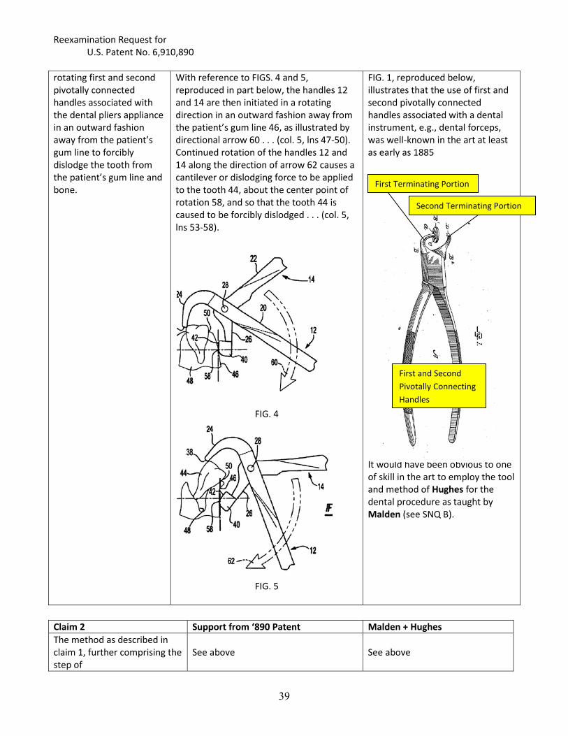
rotating first and second pivotally connected handles associated with the dental pliers appliance in an outward fashion away from the patient’s gum line to forcibly dislodge the tooth from the patient’s gum line and bone.
With reference to FIGS. 4 and 5, reproduced in part below, the handles 12 and 14 are then initiated in a rotating direction in an outward fashion away from the patient’s gum line 46, as illustrated by directional arrow 60 . . . (col. 5, lns 47-50). Continued rotation of the handles 12 and 14 along the direction of arrow 62 causes a cantilever or dislodging force to be applied to the tooth 44, about the center point of rotation 58, and so that the tooth 44 is caused to be forcibly dislodged . . . (col. 5, lns 53-58).
“In the embodiment of the invention illustrated in the drawing the clamping portion of the instrument is formed form a pair of cross members 1 and 2, the lower ends of which constitute the handle. . .” (p. 1, lns 58-64). A releasable pivot screw 6 provides a connection between the two members and serves as a fulcrum for the clamping members.” (p. 1, lns 71-74) The present invention acts on a different principle of movement
Second Terminating Portion
Inwardly facing side
Second Terminating Portion

Reexamination Request for U.S. Patent No. 6,910,890
10
FIG. 4
FIG. 5
in the extraction operation, utilizing a pivoted pull forward instead of a straight downward or upward pull on the tooth.” [Emphasis added] (p. 1, lns 49-53) By pulling forwardly on the instrument [i.e., as one would pull a lever forward about a pivot] the shank 14 will swing in an arc forwardly and extract the tooth on a forwardly extending line. The pivoting action accomplished by the pivotal disc permits the operator to utilize the principle of a lever force against the tooth instead of the ordinary movement of a straight downward or upward pull.” [Emphasis and comments added] (p. 2, lns 8-16) Clearly, the described “pivoted pull forward” tooth extraction method requires rotation of the pivotally connected handles outwardly from the gum line, identically as shown in FIGS. 4 and 5 of the ‘890 patent. Movement of shank 14 “in an arc” similar to illustrated arrows 60 and 62 of the ‘890 patent leaves no doubt about the pivoting action. FIG. 1
First and Second Pivotally Connected Handles (3)
Shank

Reexamination Request for U.S. Patent No. 6,910,890
11
Claim 2 Support from ‘890 Patent JoeschThe method as described in claim 1, further comprising the step of
See above See above
offsetting the first terminating portion from the second terminating portion and such that said first portion defines a center point of rotation proximate an edge location of the gum line.
The present invention is an improvement over prior art dental appliances due to the intentional offset or misalignment of the jaw and the pad, which allows a greater and more efficient two-component rotating force (see Col. 4, lns 27-36).
This “offset” is only apparent in the embodiment of FIGS. 1, 2, 4 and 5 (see image below). The embodiment of FIGS. 6-12 (see below) does not include the offset between the two terminating portions. Embodiment of FIGS. 1, 2, 4 and 5
Offset of the first terminating portion
Embodiment of FIGS. 6-12
No Offset
Note: For purposes of this analysis it is assumed that the “first terminating portion 24” and the “second terminating portion 26” are inexplicably reversed in the claims.
By pulling forwardly on the instrument [i.e., as one would pull a lever forward about a pivot] the shank 14 will swing in an arc forwardly and extract the tooth on a forwardly extending line. The pivoting action accomplished by the pivotal disc permits the operator to utilize the principle of a lever force against the tooth instead of the ordinary movement of a straight downward or upward pull.” [Emphasis and comments added] (p. 2, lns 8-16)
Offset of the first terminating portion
As stated above, shank 14 moves in an arc and the pivoting disc defines the center point of rotation—i.e., at the pivot 12.

Reexamination Request for U.S. Patent No. 6,910,890
12
Claim 3 Support from ‘890 Patent JoeschThe method as described in claim 1, further comprising the step of
See above See above
ergonomically configuring the first terminating portion to substantially match that of the patient’s gum.
Offset support 40 “exhibits an ergonomically configured and supporting surface 42 which is designed to substantially match that of the patient’s gum line.” (Col. 5, lns 1-4).
“A rubber cap 13 fits over the disc and the upper end of the shank.” (p. 1, lns 91-92 and FIG. 1) Rubber is commonly known to contour to match the surface to which it abuts.
Claim 4 Support from ‘890 Patent JoeschThe method as described in claim 1, further comprising the step of
See above See above
configuring the second terminating portion with a substantially pointed end.
The terminating portion 24 “exhibits an arcuately extending and substantially pointed jaw 38.” (Co. 4, lns 64-66)
As shown in FIG. 6, reproduced below (as well as FIGS. 7 and 8), the tool includes “shank 14, the upper end of which is formed with a point 15 and a concave angular recess 16 below the point.” (p. 1, lns. 92-96)
Claim 5 Support from ‘890 Patent JoeschThe method as described in claim 1, further comprising the step of
See above See above
configuring the dental pliers appliance to engage and dislodge a tooth located along a lower gum line and jaw bone of a patient.
The tool of FIGS. 1, 2, 4 and 5 is presumably for teeth located in the lower gum line and jaw bone of a patient.
Note: The pliers appliance is not actually “configured” as much as it is “switched out” for a different tool.
“Inasmuch as the jaws are interchangeable from the members 1 and 2 and the shanks are formed with the three different angles, the single pair of clamping jaws utilized with these interchangeable shanks provides an instrument whereby all of the teeth may be conveniently

Reexamination Request for U.S. Patent No. 6,910,890
13
reached for extraction.” [Emphasis added] (p. 1, lns 101-108).
Claim 6 Support from ‘890 Patent Joesch The method as described in claim 1, further comprising the step of
See above
See above
configuring the dental pliers appliance to engage and dislodge a tooth located along an upper gum line and jaw bone of a patient.
The tool of FIGS. 6-12 is “suited for removing teeth located along a patient’s upper jaw and gum line.” (Col. 6, lns. 10-16) NOTE: It is unclear how the method of Claim 1 is affected by the addition of a step requiring use of a tool for teeth in the upper gum line. For example, the method of Claim 1 requires “positioning . . . below the gum line…” This limitation, which effectively eliminates application of the claimed method to upper teeth, must be either ignored or construed against the teaching of the specification. Patent rules do not allow for a dependent claim to (implicitly or explicitly) remove a previously added claim limitation (e.g., “positioning . . . below the gum line). A method which might infringe Claim 6, could conceivably not infringe Claim 1 (see, 37 CFR 1.75(c) – a dependent claim must further limit another claim or claims).
“Inasmuch as the jaws are interchangeable from the members 1 and 2 and the shanks are formed with the three different angles, the single pair of clamping jaws utilized with these interchangeable shanks provides an instrument whereby all of the teeth may be conveniently reached for extraction.” [Emphasis added] (p. 1, lns 101-108).
Claim 7 Support from ‘890 Patent Joesch The method as described in claim 6, further comprising the step of
See above
See above
angling a side profile of the first and second pivotably connected handles.
There is no corresponding text which describes this limitation. Presumably, with reference to FIGS. 7 and 8, reproduced in part below, the “angling” refers to the curve shown in the handle of the illustrated embodiments.
It is clear from the side view of FIG. 1, the pivotably connected handles are “angled” every bit as much as those shown in the figures of the ‘890 patent.

Reexamination Request for U.S. Patent No. 6,910,890
14
NOTE: The terms “pivotally” used in Claim 1, and “pivotably” used here in Claim 7, are presumed to mean the same thing – i.e., capable of pivoting.
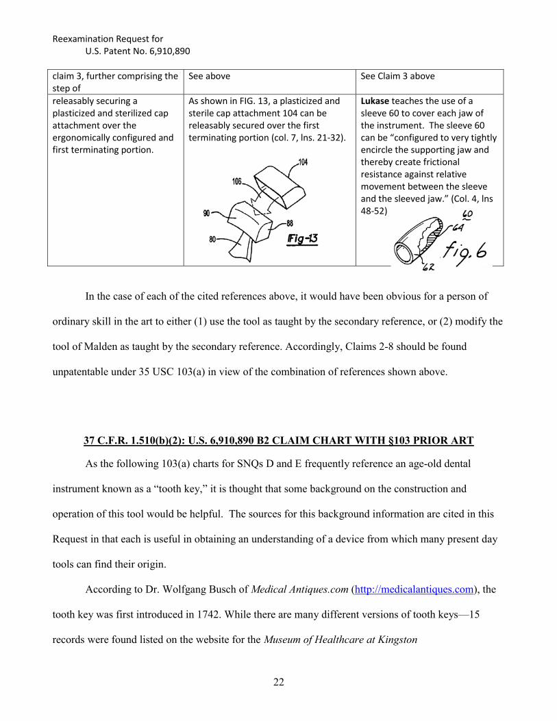
Claim 8 Support from ‘890 Patent JoeschThe method as described in claim 3, further comprising the step of
See above See above
releasably securing a plasticized and sterilized cap attachment over the ergonomically configured and first terminating portion.
As shown in FIG. 13, a plasticized and sterile cap attachment 104 can be releasably secured over the first terminating portion (col. 7, lns. 21-32).
“A rubber cap 13 fits over the disc and the upper end of the shank.” (p. 1, lns 91-92 and FIG. 1)
Partial Reproduction of FIG. 1 shows cap 13.

Reexamination Request for U.S. Patent No. 6,910,890
15
37 C.F.R. 1.510(b)(2): U.S. 6,910,890 B2 CLAIM CHART WITH §102 PRIOR ART Claim 1 [SNQ B]
Claim 1 Support from ‘890 Patent Malden A method for removing teeth from a dental patient’s gum line and bone, said method comprising the steps of:
A dental pliers appliance and associated method for removing teeth from a patient’s gum line and bone (Abst.). FIGS. 4 and 5 illustrate the dental appliance tool and method of operation according to the present invention (col. 5, lns. 36-39)
The Reference discloses two new elevator and dental forceps techniques for atraumatic removal of teeth (Abst). Technique 2 describes extraction of tooth roots from a patient’s gum line and bone. (p. 43)
positioning a first terminating portion of dental pliers appliance along a selection1 location below the gum line;
1 The term “selection” is presumed to be a typographical error which should read “selected”.
FIG. 1 (and FIG. 2), reproduced in part below, illustrate terminating portion 24 associated with first handle 12 and having “an arcuately extending and substantially pointed jaw 38.” Also, the second terminating portion 26, associated with second handle 14, includes “a three dimensional and offset support 40.” (col. 4, ln 64 – col. 5, ln. 1).
However, FIG. 4, reproduced in part below, illustrates support 40 of the second terminating portion 26 in position along a selected location of the patient’s gun 46 below the gum line 50 (see col. 5, lns 40-42)
Under “Technique 2,” Stage 2 of the disclosed technique requires the buccal beak (i.e., first terminating portion) to be positioned onto the mucosa and pierce down to rest on the outer aspect of the buccal bone (see p. 43 and Figures 10 and 11). This instruction is repeated under FIGS. 10 and 11 reproduced below, which states that the buccal beak (first terminating portion) should be placed onto mucosa and pierced down to rest on the outer aspect of the buccal bone. This is below the gum line as required.
Figure 10
Figure 11
The terminating portion of the forceps can be seen in Figure 11 clearly below the gum line.
First Terminating Portion
First Terminating Portion
Gum line
First Terminating Portion
Gum line
Gum line

Reexamination Request for U.S. Patent No. 6,910,890
16
positioning a second terminating portion of the dental pliers appliance against an inwardly facing side of a selected tooth projecting from the gum line;
FIG. 1 (and FIG. 2), reproduced in part below, illustrate the second terminating portion 26, associated with second handle 14, includes “a three dimensional and offset support 40.” (col. 4, ln 64 – col. 5, ln. 1).
However, FIG. 4, reproduced in part below, illustrates pointed jaw 38 of the terminating portion 24 positioned against an inwardly facing side of a tooth (see col. 5, lns 43-45)
Under “Technique 2,” Stage 1 of the technique calls for placing “lingual beak of forceps in conventional position (Figure 10).” (see p. 43)
Again, this instruction is repeated under FIG. 10 reproduced below, which states that the lingual beak (i.e., second terminating portion) of the forceps is placed in the “conventional position” while showing the beak engaging the inwardly side of a tooth.
rotating first and second pivotally connected handles associated with the dental pliers appliance in an outward fashion away from the patient’s gum line to forcibly dislodge the tooth from the patient’s gum line and bone.
With reference to FIGS. 4 and 5, reproduced in part below, the handles 12 and 14 are then initiated in a rotating direction in an outward fashion away from the patient’s gum line 46, as illustrated by directional arrow 60 . . . (col. 5, lns 47-50). Continued rotation of the handles 12 and 14 along the direction of arrow 62 causes a cantilever or dislodging force to be applied to the tooth 44, about the center point of rotation 58, and so that the tooth 44 is caused to be forcibly dislodged . . . (col. 5, lns 53-58).
Stage 3 of the technique directs the dentist to “carefully close forceps, using downward pressure to prevent the buccal beak [i.e., first terminating portion] slipping coronally up the buccal bone (Figure 12).” Figure 12 is reproduced below. The illustration shows first and second pivotally connected handles (see small arrows) of the standard forceps being rotated (see large arrow) in the identical manner of the ‘890 patent FIGS. 4 and 5.
Second Terminating Portion
Inwardly facing side
Inwardly facing side
Second Terminating Portion

Reexamination Request for U.S. Patent No. 6,910,890
17
FIG. 4
FIG. 5
Clearly, this reference teaches a person of skill in the art to rotate the forceps in an “outward” fashion away from the patient’s gum line to remove tooth roots.
Rotation of pivotally connected handles

Reexamination Request for U.S. Patent No. 6,910,890
18
37 C.F.R. 1.510(b)(2): U.S. 6,910,890 B2 CLAIM CHART WITH §103 PRIOR ART
Claims 2-8 [SNQ C]
Claim 2 Support from ‘890 Patent Malden + Maeda The method as described in claim 1, further comprising the step of
See above
See SNQ B above
offsetting the first terminating portion from the second terminating portion and such that said first portion defines a center point of rotation proximate an edge location of the gum line.
The present invention is an improvement over prior art dental appliances due to the intentional offset or misalignment of the jaw and the pad, which allows a greater and more efficient two-component rotating force (see Col. 4, lns 27-36). This “offset” is only apparent in the embodiment of FIGS. 1, 2, 4 and 5 (see image below). The embodiment of FIGS. 6-12 (see below) does not include the offset between the two terminating portions. Embodiment of FIGS. 1, 2, 4 and 5
Offset of the first terminating portion
Embodiment of FIGS. 6-12
No Offset
With reference to FIG. 6 of Maeda, reproduced in part below, the first terminating portion is clearly offset from the second terminating portion which would define a center point of rotation proximate an edge location of the gum line.
First Terminating Portion
Offset of the first terminating portion
As both Malden and Maeda are directed to dental instruments and dental methods, it would have been obvious to a person of skill in the art to modify the forceps of Malden as taught by Maeda to provide a better center point of rotation for the tooth extraction process.

Reexamination Request for U.S. Patent No. 6,910,890
19
Claim 3 Support from ‘890 Patent Malden + Hamilton or Arnott The method as described in claim 1, further comprising the step of
See above See SNQ B above
ergonomically configuring the first terminating portion to substantially match that of the patient’s gum.
Offset support 40 “exhibits an ergonomically configured and supporting surface 42 which is designed to substantially match that of the patient’s gum line.” (Col. 5, lns 1-4).
Hamilton – The gripping surface 9 preferably has a serrated surface which conforms to the occlusal surface of the acrylic appliance when the apparatus is engaged. (Col. 4, lns 8-15) Also, see FIG. 1 reproduced in part below:
As both Malden and Hamilton are directed to dental instruments and dental methods, it would have been obvious to a person of skill in the art to modify the forceps of Malden as taught by Hamilton to provide a less injurious first terminating portion to match a patient’s gum. Arnott – The reference describes a manner of using tooth keys (discussed infra), but the states that “Some dentists, by a strong forceps made for the purpose, pull teeth directly out; . . . and others use a forceps in the manner of the tooth-key, by resting one side of it on the gum as a fulcrum, and then giving it a twisting motion: in the latter case the resting side of the fulcrum is formed like the bolster of a tooth key.” (i.e., configured to match the patient’s gum).
First Terminating Portion

Reexamination Request for U.S. Patent No. 6,910,890
20
Claim 4 Support from ‘890 Patent Malden + Maeda The method as described in claim 1, further comprising the step of
See above See SNQ B above
configuring the second terminating portion with a substantially pointed end.
The terminating portion 24 “exhibits an arcuately extending and substantially pointed jaw 38.” (Co. 4, lns 64-66)
The second terminating portion of Maeda comprises a pointed end.
Claim 5 Support from ‘890 Patent Malden + White The method as described in claim 1, further comprising the step of
See above See SNQ B above
configuring the dental pliers appliance to engage and dislodge a tooth located along a lower gum line and jaw bone of a patient.
The tool of FIGS. 1, 2, 4 and 5 is presumably for teeth located in the lower gum line and jaw bone of a patient.
Note: The pliers appliance is not actually “configured” as much as it is “switched out” for a different tool.
White illustrates a Fulcrum Forceps instrument No. 2 for lower incisors, cuspids and bicuspids (p. 44) and No. 3 for lower molars (p. 45). Each instrument includes a plate with an India-rubber pad for placement against the patient’s gum.
It would have been obvious to a person of skill in the art to use the forceps instruments of White for the tooth extraction process as taught by Malden.
Claim 6 Support from ‘890 Patent Malden + White The method as described in claim 1, further comprising the step of
See above See SNQ B above
configuring the dental pliers appliance to engage and dislodge a tooth located along an upper gum line and jaw
The tool of FIGS. 6-12 is “suited for removing teeth located along a patient’s upper jaw and gum line.” (Col. 6, lns. 10-16)
White illustrates a Fulcrum Forceps instrument No. 1 for upper incisors, cuspids and bicuspids (p. 44) and No. 4 for
Second Terminating Portion

Reexamination Request for U.S. Patent No. 6,910,890
21
bone of a patient. upper molars (p. 45). Each instrument includes a plate with an India-rubber pad for placement against the patient’s gum.
It would have been obvious to a person of skill in the art to use the forceps instruments of White for the tooth extraction process as taught by Malden.
Claim 7 Support from ‘890 Patent Malden + White + Garretson The method as described in claim 6, further comprising the step of
See above See Claim 6 above
angling a side profile of the first and second pivotably connected handles.
There is no corresponding text which describes this limitation. Presumably, with reference to FIGS. 7 and 8, reproduced in part below, the “angling” refers to the curve shown in the handle of the illustrated embodiments.
NOTE: The terms “pivotally” used in Claim 1, and “pivotably” used here in Claim 7, are presumed to mean the same thing – i.e., capable of pivoting.
Garretson – In the side view of FIG. 282 on p. 392, the illustrated fulcrum forceps (marked as being manufactured and sold by S.S. White) have pivotable handles which are “angled” in at least two planes every bit as much as those shown in the figures of the ‘890 patent.
It would have been obvious to a person of skill in the art to use the forceps instruments of White as illustrated in Garretson for the tooth extraction process as taught by Malden.
Claim 8 Support from ‘890 Patent Malden + Hamilton + Lukase The method as described in
Reexamination Request for U.S. Patent No. 6,910,890
22
claim 3, further comprising the step of
See above See Claim 3 above
releasably securing a plasticized and sterilized cap attachment over the ergonomically configured and first terminating portion.
As shown in FIG. 13, a plasticized and sterile cap attachment 104 can be releasably secured over the first terminating portion (col. 7, lns. 21-32).
Lukase teaches the use of a sleeve 60 to cover each jaw of the instrument. The sleeve 60 can be “configured to very tightly encircle the supporting jaw and thereby create frictional resistance against relative movement between the sleeve and the sleeved jaw.” (Col. 4, lns 48-52)
In the case of each of the cited references above, it would have been obvious for a person of
ordinary skill in the art to either (1) use the tool as taught by the secondary reference, or (2) modify the
tool of Malden as taught by the secondary reference. Accordingly, Claims 2-8 should be found
unpatentable under 35 USC 103(a) in view of the combination of references shown above.
37 C.F.R. 1.510(b)(2): U.S. 6,910,890 B2 CLAIM CHART WITH §103 PRIOR ART
As the following 103(a) charts for SNQs D and E frequently reference an age-old dental
instrument known as a “tooth key,” it is thought that some background on the construction and
operation of this tool would be helpful. The sources for this background information are cited in this
Request in that each is useful in obtaining an understanding of a device from which many present day
tools can find their origin.
According to Dr. Wolfgang Busch of Medical Antiques.com (http://medicalantiques.com), the
tooth key was first introduced in 1742. While there are many different versions of tooth keys—15
records were found listed on the website for the Museum of Healthcare at Kingston

Reexamination Request for U.S. Patent No. 6,910,890
23
(http://www.museumofhealthcare.ca)—the key is basically comprised of a handle, a shaft and a bolster
and hook attached to the shaft at an end opposite the handle.
The image below is an illustration of dental keys (aka, tooth keys) for tooth extraction taken
from “Savigny’s Catalog of Surgery Implements” (circa 1798) as published in “Bloodletting, Bone
Brushes, and Tooth Keys: White-Knuckle Adventures in Early Dentistry” by Hunter Oatman-Stanford
(Collectors Weekly, September 3rd, 2014). The bottom right corner images illustrate engagement of a
tooth by the tooth key.
In “Elements of Physics” (by Arnott & Hays, publisher Lea & Blanchard, PA, 1838) the use
and operation of the tooth key is compared “to a wheel and axle, the hand of the operator acting on two
spokes of the wheel to work it, while the tooth is fixed to the axle by the claw, and is drawn out as the
axle turns.”
Image of Tooth Keys
Additional image below also illustrates how a tooth was engaged by a “tooth key” styled
instruments (http://www.dmd.co.il/antiques/big_he.html):

Reexamination Request for U.S. Patent No. 6,910,890
24
It is with this knowledge of the construction and operation of the tooth key as a dental
instrument that the following very old references will be more readily understood.

Reexamination Request for U.S. Patent No. 6,910,890
25
Claims 1-7 [SNQ D]
Claim 1 Support from ‘890 Patent Baker + Ring A method for removing teeth from a dental patient’s gum line and bone, said method comprising the steps of:
A dental pliers appliance and associated method for removing teeth from a patient’s gum line and bone (Abst.). FIGS. 4 and 5 illustrate the dental appliance tool and method of operation according to the present invention (col. 5, lns. 36-39)
Baker – “Instrument for Extracting Teeth” (Title on p. 2) Ring – Etienne Bourdet (1722-1789) first described “keys” as an instrument for extracting teeth in his published papers (first published in 1757). (p. 147) In American colonial times, “physicians became proficient in the use of the key for tooth extraction…” (p. 183)
positioning a first terminating portion of dental pliers appliance along a selection location below the gum line;
FIG. 4, reproduced in part below, illustrates support 40 of the second terminating portion 26 in position along a selected location of the patient’s gun 46 below the gum line 50 (see col. 5, lns 40-42) NOTE: The “First” and “Second” terminating portions are reversed in the issued claims.
Baker – The bulb, or fulcrum [i.e., first terminating portion] is made about three fourths of an inch long by half an inch thick and in shape resembling a pear at side view, letter B.” (p. 2, lns. 21-25; also see image below).
Ring – The below illustration is a drawing from a publication of 1815 depicting the extraction of a tooth using a tooth-key (see FIG. 8 on p. 214).
Gum line
Gum line
First Terminating Portion
First Terminating Portion First Terminating Portion

Reexamination Request for U.S. Patent No. 6,910,890
26
While Baker does not describe the use of the disclosed instrument, which is an improved version of a tooth key, Ring clearly illustrates how the instrument is used. Specifically, the illustration shows the “bulb or fulcrum” of the instrument being positioned at a location “below the gum line.”
positioning a second terminating portion of the dental pliers appliance against an inwardly facing side of a selected tooth projecting from the gum line;
FIG. 4, reproduced in part below, illustrates pointed jaw 38 of the terminating portion 24 positioned against an inwardly facing side of a tooth (see col. 5, lns 43-45)
Baker – “The hook [i.e., second terminating portion], is of the usual form at the point . . . which we are enabled to prevent the hook from slipping from the tooth, . . .” (p. 2, lns 46-56)
Ring - Again, while Baker does not describe the use of the disclosed instrument (i.e., an improved tooth key), Ring clearly illustrates how the instrument is used. Specifically, the illustration shows the “hook” of the instrument being positioned “against an inwardly facing side” of a tooth.
Inwardly facing side
Inwardly facing side
Second Terminating Portion
Second Terminating Portion

Reexamination Request for U.S. Patent No. 6,910,890
27
rotating first and second pivotally connected handles associated with the dental pliers appliance in an outward fashion away from the patient’s gum line to forcibly dislodge the tooth from the patient’s gum line and bone.
With reference to FIGS. 4 and 5, reproduced in part below, the handles 12 and 14 are then initiated in a rotating direction in an outward fashion away from the patient’s gum line 46, as illustrated by directional arrow 60 . . . (col. 5, lns 47-50). Continued rotation of the handles 12 and 14 along the direction of arrow 62 causes a cantilever or dislodging force to be applied to the tooth 44, about the center point of rotation 58, and so that the tooth 44 is caused to be forcibly dislodged . . . (col. 5, lns 53-58).
FIG. 4
FIG. 5
Baker – “The nature of our improvement consists in applying lever power to the hook, either by forcep handles, as in the accompanying drawings . . .” (p. 2, lns 10-12) “We construct a pair of forcep handles and joint, as represented in the accompanying drawing letter A, or any of the known forms.” (p. 2, lns 18-21 and the figure below) The reference also mentions preventing “the hook from slipping from the tooth, while turning it out . . .” (p. 2, lns 55-56) which implies rotation.
Ring – While not explicitly describing the movement as “rotating,” the Fig. 9 illustration below following Fig. 8 above, clearly shows rotation of the tooth-key about fulcrum “d” to dislodge the tooth.
First and second pivotally connected handles

Reexamination Request for U.S. Patent No. 6,910,890
28
While Ring does not disclose the tooth-key as having first and second “pivotally connected” handles, Baker clearly does and it would have been obvious to those of skill in the art to use the instrument of Baker to perform the method disclosed by Ring. Further, the “pivotable” nature of the handles seem inconsequential to the claimed method as it does not rely on the handles for anything other than imparting rotational movement, which can be achieved whether the handles are pivotally connected or not.
Claim 2 Support from ‘890 Patent Baker + Ring The method as described in claim 1, further comprising the step of
See above See above
offsetting the first terminating portion from the second terminating portion and such that said first portion defines a center point of rotation proximate an edge location of the gum line.
The present invention is an improvement over prior art dental appliances due to the intentional offset or misalignment of the jaw and the pad, which allows a greater and more efficient two-component rotating force (see Col. 4, lns 27-36). This “offset” is only apparent in the embodiment of FIGS. 1, 2, 4 and 5 (see image below). The embodiment of FIGS. 6-12 does not include the offset between the two terminating portions.
Embodiment of FIGS. 1, 2, 4 and 5
Offset of the first terminating portion
Baker – In an open position, as shown by the image reproduced below, there is a significant “offset” between the first and second terminating portions.
Offset of the first terminating portion This offset is more clearly shown in FIG. 9 of Ring, reproduced below. Further, the center point of rotation, marked by the crossing lines of FIG. 9, is also clearly through the fulcrum of the instrument, positioned proximate an edge of the gum

Reexamination Request for U.S. Patent No. 6,910,890
29
line. Pivot C is only a hinge point between the fulcrum and hook to allow opening, but rotation occurs during use about an axis through the fulcrum.
Center point of Rotation
Claim 3 Support from ‘890 Patent Baker + Ring The method as described in claim 1, further comprising the step of
See above See above
ergonomically configuring the first terminating portion to substantially match that of the patient’s gum.
Offset support 40 “exhibits an ergonomically configured and supporting surface 42 which is designed to substantially match that of the patient’s gum line.” (Col. 5, lns 1-4).
The fulcrum in both Baker and Ring has a rounded base which is well-suited to match a patient’s gum.
Claim 4 Support from ‘890 Patent Baker + Ring The method as described in claim 1, further comprising the step of
See above See above
configuring the second terminating portion with a substantially pointed end.
The terminating portion 24 “exhibits an arcuately extending and substantially pointed jaw 38.” (Co. 4, lns 64-66)
The hook of Baker and the claw of Ring are clearly pointed at the end.
Claim 5 Support from ‘890 Patent Baker + Ring The method as described in claim 1, further comprising the step of
See above See above
configuring the dental pliers appliance to engage and dislodge a tooth located along a lower gum line and jaw bone of a patient.
The tool of FIGS. 1, 2, 4 and 5 is presumably for teeth located in the lower gum line and jaw bone of a patient.
Neither Baker nor Ring is limited to the upper or lower teeth of the patient. Both instruments are clearly useful for extracting upper and lower teeth.

Reexamination Request for U.S. Patent No. 6,910,890
30
Claim 6 Support from ‘890 Patent Baker + Ring The method as described in claim 1, further comprising the step of
See above See above
configuring the dental pliers appliance to engage and dislodge a tooth located along an upper gum line and jaw bone of a patient.
The tool of FIGS. 6-12 is “suited for removing teeth located along a patient’s upper jaw and gum line.” (Col. 6, lns. 10-16)
Neither Baker nor Ring is limited to the upper or lower teeth of the patient. Both instruments are clearly useful for extracting upper and lower teeth.
Claim 7 Support from ‘890 Patent Baker + Ring The method as described in claim 6, further comprising the step of
See above See above
angling a side profile of the first and second pivotably connected handles.
There is no corresponding text which describes this limitation. Presumably, with reference to FIGS. 7 and 8, reproduced in part below, the “angling” refers to the curve shown in the handle of the illustrated embodiments.
The handles of Baker are most clearly angled about several planes, including a side profile. That is, the handles angle inward from the wider ends to the narrow shaft, as well as angling outward and back, including the 90 degree flip at the end of one handle.

Reexamination Request for U.S. Patent No. 6,910,890
31
37 C.F.R. 1.510(b)(2): U.S. 6,910,890 B2 CLAIM CHART WITH §103 PRIOR ART
Claims 1-8 [SNQ E]
Claim 1 Support from ‘890 Patent Baker + Fillebrown A method for removing teeth from a dental patient’s gum line and bone, said method comprising the steps of:
A dental pliers appliance and associated method for removing teeth from a patient’s gum line and bone (Abst.). FIGS. 4 and 5 illustrate the dental appliance tool and method of operation according to the present invention (col. 5, lns. 36-39)
Baker – “Instrument for Extracting Teeth” (Title on p. 2)
Fillebrown – Describes use of the tooth key, a device for extracting teeth used by Dr. Fillebrown from about 1830 through 1885 (First paragraph of p. 69).
positioning a first terminating portion of dental pliers appliance along a selection location below the gum line;
FIG. 4, reproduced in part below, illustrates support 40 of the second terminating portion 26 in position along a selected location of the patient’s gun 46 below the gum line 50 (see col. 5, lns 40-42) NOTE: The “First” and “Second” terminating portions are reversed in the issued claims.
Baker – The bulb, or fulcrum [i.e., first terminating portion] is made about three fourths of an inch long by half an inch thick and in shape resembling a pear at side view, letter B.” (p. 2, lns. 21-25; also see image below).
Fillebrown – The fulcrum should be neither too large nor too small (p. 71, 1st full paragraph) When padded, place the fulcrum on the inside of the jaw, opposite the tooth to be extracted, and rest it on the edge of the gum, well up on the neck of the tooth (p. 71, 3rd paragraph) While the above placement is for “inside the jaw,” Fillebrown states the “adaptability of the instrument is shown by the variety of ways in which it is used.” For example, he notes “Dr. Preston, of Boston, has used the
Gum line
First Terminating Portion First Terminating Portion

Reexamination Request for U.S. Patent No. 6,910,890
32
key successfully for more than forty years . . . and always places the fulcrum on the outside of the jaw, turning the tooth outward, . . .” (p. 73, 1st full paragraph) The below FIG. 3 from Fillebrown illustrates the positioning of the fulcrum (i.e., first terminating portion).
While Baker does not describe the use of the disclosed instrument, which is an improved version of a tooth key, Fillebrown clearly describes and illustrates how the instrument is used. Specifically, the illustration shows the fulcrum of the instrument being positioned at a location “below the gum line.”
positioning a second terminating portion of the dental pliers appliance against an inwardly facing side of a selected tooth projecting from the gum line;
FIG. 4, reproduced in part below, illustrates pointed jaw 38 of the terminating portion 24 positioned against an inwardly facing side of a tooth (see col. 5, lns 43-45)
Baker – “The hook [i.e., second terminating portion], is of the usual form at the point . . . which we are enabled to prevent the hook from slipping from the tooth, . . .” (p. 2, lns 46-56)
Fillebrown – If the tooth be strong, place the point of the
Inwardly facing side
Second Terminating Portion
First Terminating Portion
Second Terminating Portion
Gum line

Reexamination Request for U.S. Patent No. 6,910,890
33
hook on the neck of the outside of the tooth, pressing down the gum a little, but not sufficient to wound it. (p. 71, last paragraph) See also FIG. 3 below:
Again, while Baker does not describe the use of the disclosed instrument (i.e., an improved tooth key), Fillebrown clearly illustrates how the instrument is used. Specifically, the illustration shows the “hook” of the instrument being positioned “against an [outwardly] facing side” of a tooth. However, Fillebrown notes “Dr. Preston, of Boston, has used the key successfully for more than forty years . . . and always places the fulcrum on the outside of the jaw, turning the tooth outward, . . .” (p. 73, 1st full paragraph) Such use would require the hook to engage the “inward facing side” of the tooth.
rotating first and second pivotally connected handles associated with the dental pliers appliance in an outward fashion away from the patient’s gum line to forcibly dislodge the tooth from the patient’s gum line and bone.
With reference to FIGS. 4 and 5, reproduced in part below, the handles 12 and 14 are then initiated in a rotating direction in an outward fashion away from the patient’s gum line 46, as illustrated by directional arrow 60 . . . (col. 5, lns 47-50). Continued rotation of the handles 12 and 14 along the direction of arrow 62 causes a cantilever or dislodging force to be applied to the tooth 44, about the center point of rotation 58, and so that the tooth 44 is caused to be forcibly dislodged . . . (col. 5, lns 53-58).
Baker – “The nature of our improvement consists in applying lever power to the hook, either by forcep handles, as in the accompanying drawings . . .” (p. 2, lns 10-12) “We construct a pair of forcep handles and joint, as represented in the accompanying drawing letter A, or any of the known forms.” (p. 2, lns 18-21 and the figure below) The reference also mentions preventing “the hook from
Second Terminating Portion

Reexamination Request for U.S. Patent No. 6,910,890
34
FIG. 4
FIG. 5
slipping from the tooth, while turning it out . . .” (p. 2, lns 55-56) which implies rotation.
Fillebrown – In describing the use by Dr. Preston, he states he “always places the fulcrum on the outside of the jaw, turning the tooth outward, . . .” (p. 73) This language implies rotation, exactly as shown in FIGS. 4 and 5 of the ‘890 patent. While Fillebrown does not disclose the tooth-key as having first and second “pivotally connected” handles, Baker clearly does and it would have been obvious to those of skill in the art to use the modified tooth key instrument of Baker to perform the tooth key method disclosed by Fillebrown.
Claim 2 Support from ‘890 Patent Baker + Fillebrown The method as described in claim 1, further comprising the step of
See above See above
offsetting the first terminating portion from the second terminating portion and such that said first portion defines a
The present invention is an improvement over prior art dental appliances due to the intentional offset or misalignment of the jaw and the
Baker – In an open position, as shown by the image reproduced below, there is a significant “offset” between the first and
First and second pivotally connected handles

Reexamination Request for U.S. Patent No. 6,910,890
35
center point of rotation proximate an edge location of the gum line.
pad, which allows a greater and more efficient two-component rotating force (see Col. 4, lns 27-36). This “offset” is only apparent in the embodiment of FIGS. 1, 2, 4 and 5 (see image below). The embodiment of FIGS. 6-12 does not include the offset between the two terminating portions.
Embodiment of FIGS. 1, 2, 4 and 5
Offset of the first terminating portion
second terminating portions.
Offset of the first terminating portion
This offset is also shown in FIG. 3 of Fillebrown, reproduced below. Further, the center point of rotation, marked by the crossing lines on FIG. 3, is also clearly through the fulcrum of the instrument, positioned proximate an edge of the gum line. Pivot S is only a hinge point between the fulcrum and hook to allow opening, but rotation occurs during use about an axis through the fulcrum. Center point of Rotation
Claim 3 Support from ‘890 Patent Baker + Fillebrown The method as described in claim 1, further comprising the step of
See above See above
ergonomically configuring the first terminating portion to
Offset support 40 “exhibits an ergonomically configured and
The fulcrum in both Baker and Fillebrown has a rounded base

Reexamination Request for U.S. Patent No. 6,910,890
36
substantially match that of the patient’s gum.
supporting surface 42 which is designed to substantially match that of the patient’s gum line.” (Col. 5, lns 1-4).
which is well-suited to match a patient’s gum.
Claim 4 Support from ‘890 Patent Baker + Fillebrown The method as described in claim 1, further comprising the step of
See above
See above
configuring the second terminating portion with a substantially pointed end.
The terminating portion 24 “exhibits an arcuately extending and substantially pointed jaw 38.” (Co. 4, lns 64-66)
The hook of both Baker and Fillebrown are clearly pointed at the end.
Claim 5 Support from ‘890 Patent Baker + Fillebrown The method as described in claim 1, further comprising the step of
See above
See above
configuring the dental pliers appliance to engage and dislodge a tooth located along a lower gum line and jaw bone of a patient.
The tool of FIGS. 1, 2, 4 and 5 is presumably for teeth located in the lower gum line and jaw bone of a patient.
Neither Baker nor Fillebrown is limited to the upper or lower teeth of the patient. Both instruments are clearly useful for extracting upper and lower teeth.
Claim 6 Support from ‘890 Patent Baker + Fillebrown The method as described in claim 1, further comprising the step of
See above
See above
configuring the dental pliers appliance to engage and dislodge a tooth located along an upper gum line and jaw bone of a patient.
The tool of FIGS. 6-12 is “suited for removing teeth located along a patient’s upper jaw and gum line.” (Col. 6, lns. 10-16)
Neither Baker nor Fillebrown is limited to the upper or lower teeth of the patient. Both instruments are clearly useful for extracting upper and lower teeth.
Claim 7 Support from ‘890 Patent Baker + Fillebrown The method as described in claim 6, further comprising the step of
See above
See above
angling a side profile of the first and second pivotably connected handles.
There is no corresponding text which describes this limitation. Presumably, with reference to FIGS. 7 and 8, reproduced in part below, the “angling” refers to the curve shown in the handle of the illustrated embodiments.
The handles of Baker are most clearly angled about several planes, including a side profile. That is, the handles angle inward from the wider ends to the narrow shaft, as well as angling outward and back, including the 90 degree flip at the end of one

Reexamination Request for U.S. Patent No. 6,910,890
37
handle.
Claim 8 Support from ‘890 Patent Baker + Fillebrown The method as described in claim 3, further comprising the step of
See above See above
releasably securing a plasticized and sterilized cap attachment over the ergonomically configured and first terminating portion.
As shown in FIG. 13, a plasticized and sterile cap attachment 104 can be releasably secured over the first terminating portion (col. 7, lns. 21-32).
Fillebrown – When used the bulb of the key should be covered with a pad. The use of it without is likely to bruise the gum. A permanent pad of any kind I dislike, as it becomes foul in spite of care.
The “p” represents a “pad” on the fulcrum.
It would have been obvious at the time of the “invention” for one of ordinary skill in the art to
combine the teachings of Baker with the teachings of both Ring and Fillebrown because each reference
is directed to the use of a tooth key as a dental instrument, specifically its use for extracting teeth from
a patient’s gum line. Those of skill in the art would have been motivated to use the teachings from the

Reexamination Request for U.S. Patent No. 6,910,890
38
cited references to develop a method for removing teeth from a dental patient’s gum line and bone as
set forth in Claims 1-8 of the ‘890 patent.
37 C.F.R. 1.510(b)(2): U.S. 6,910,890 B2 CLAIM CHART WITH §103 PRIOR ART
Claims 1-6 [SNQ F]
Claim 1 Support from ‘890 Patent Malden + Hughes A method for removing teeth from a dental patient’s gum line and bone, said method comprising the steps of:
A dental pliers appliance and associated method for removing teeth from a patient’s gum line and bone (Abst.).
FIGS. 4 and 5 illustrate the dental appliance tool and method of operation according to the present invention (col. 5, lns. 36-39)
Malden – See SNQ B above Hughes – Invention relates to forceps for dentists’ use, and adapted especially for extracting roots of teeth (lines 11-13).
positioning a first terminating portion of dental pliers appliance along a selection location below the gum line;
FIG. 4, reproduced in part below, illustrates support 40 of the second terminating portion 26 in position along a selected location of the patient’s gun 46 below the gum line 50 (see col. 5, lns 40-42)
Hughes – FIG. 2, reproduced in part below, illustrates a terminating portion of the disclosed forceps including a swiveling pad at B’.
The pad B’ allows this portion to be placed against a patient’s gum to prevent injury as pressure is applied.
positioning a second terminating portion of the dental pliers appliance against an inwardly facing side of a selected tooth projecting from the gum line;
FIG. 4 illustrates pointed jaw 38 of the terminating portion 24 positioned against an inwardly facing side of a tooth (see col. 5, lns 43-45)
FIG. 3, reproduced in part below, illustrates another terminating portion of the disclosed dental instrument. This portion has a beak (“c”) at the end “to permit it to fit upon the root of a tooth.”
First Terminating Portion
Gum line
First Terminating Portion
Second Terminating Portion
Second Terminating Portion
Reexamination Request for U.S. Patent No. 6,910,890
39
rotating first and second pivotally connected handles associated with the dental pliers appliance in an outward fashion away from the patient’s gum line to forcibly dislodge the tooth from the patient’s gum line and bone.
With reference to FIGS. 4 and 5, reproduced in part below, the handles 12 and 14 are then initiated in a rotating direction in an outward fashion away from the patient’s gum line 46, as illustrated by directional arrow 60 . . . (col. 5, lns 47-50). Continued rotation of the handles 12 and 14 along the direction of arrow 62 causes a cantilever or dislodging force to be applied to the tooth 44, about the center point of rotation 58, and so that the tooth 44 is caused to be forcibly dislodged . . . (col. 5, lns 53-58).
FIG. 4
FIG. 5
FIG. 1, reproduced below, illustrates that the use of first and second pivotally connected handles associated with a dental instrument, e.g., dental forceps, was well-known in the art at least as early as 1885
It would have been obvious to one of skill in the art to employ the tool and method of Hughes for the dental procedure as taught by Malden (see SNQ B).
Claim 2 Support from ‘890 Patent Malden + HughesThe method as described in claim 1, further comprising the step of
See above See above
ld h b b i t
First Terminating Portion
Second Terminating Portion
First and Second Pivotally Connecting Handles
Reexamination Request for U.S. Patent No. 6,910,890
40
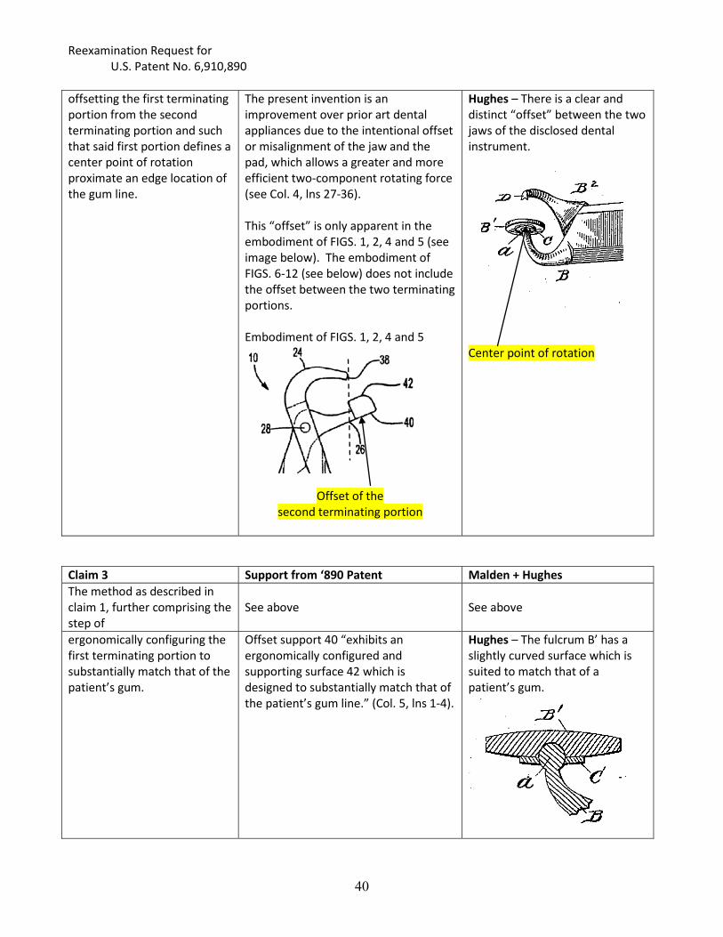
offsetting the first terminating portion from the second terminating portion and such that said first portion defines a center point of rotation proximate an edge location of the gum line.
The present invention is an improvement over prior art dental appliances due to the intentional offset or misalignment of the jaw and the pad, which allows a greater and more efficient two-component rotating force (see Col. 4, lns 27-36).
This “offset” is only apparent in the embodiment of FIGS. 1, 2, 4 and 5 (see image below). The embodiment of FIGS. 6-12 (see below) does not include the offset between the two terminating portions. Embodiment of FIGS. 1, 2, 4 and 5
Offset of the second terminating portion
Hughes – There is a clear and distinct “offset” between the two jaws of the disclosed dental instrument.
Center point of rotation
Claim 3 Support from ‘890 Patent Malden + Hughes The method as described in claim 1, further comprising the step of
See above See above
ergonomically configuring the first terminating portion to substantially match that of the patient’s gum.
Offset support 40 “exhibits an ergonomically configured and supporting surface 42 which is designed to substantially match that of the patient’s gum line.” (Col. 5, lns 1-4).
Hughes – The fulcrum B’ has a slightly curved surface which is suited to match that of a patient’s gum.

Reexamination Request for U.S. Patent No. 6,910,890
41
Claim 4 Support from ‘890 Patent Malden + Hughes The method as described in claim 1, further comprising the step of
See above See above
configuring the second terminating portion with a substantially pointed end.
The terminating portion 24 “exhibits an arcuately extending and substantially pointed jaw 38.” (Co. 4, lns 64-66)
Hughes – The second terminating end includes a substantially pointed end.
Claim 5 Support from ‘890 Patent Malden + Hughes The method as described in claim 1, further comprising the step of
See above See above
configuring the dental pliers appliance to engage and dislodge a tooth located along a lower gum line and jaw bone of a patient.
The tool of FIGS. 1, 2, 4 and 5 is presumably for teeth located in the lower gum line and jaw bone of a patient.
Hughes – The disclosed dental instrument is not limited to any particular teeth, including upper and lower teeth.
Claim 6 Support from ‘890 Patent Malden + Hughes The method as described in claim 1, further comprising the step of
See above See above
configuring the dental pliers appliance to engage and dislodge a tooth located along an upper gum line and jaw bone of a patient.
The tool of FIGS. 6-12 is “suited for removing teeth located along a patient’s upper jaw and gum line.” (Col. 6, lns. 10-16)
Hughes – The disclosed dental instrument is not limited to any particular teeth, including upper and lower teeth.

Reexamination Request for U.S. Patent No. 6,910,890
42
37 C.F.R. 1.510(b)(2): U.S. 6,910,890 B2 CLAIM CHART WITH §103 PRIOR ART
Claims 5-6 [SNQ G]
Claim 5 Support from ‘890 Patent Malden + Hughes + Christensen The method as described in claim 1, further comprising the step of
See above
M + H – See SNQ F above Christensen – This invention relates to improved forceps for extracting teeth of people. (Col. 1, lns 1-2)
configuring the dental pliers appliance to engage and dislodge a tooth located along a lower gum line and jaw bone of a patient.
The tool of FIGS. 1, 2, 4 and 5 is presumably for teeth located in the lower gum line and jaw bone of a patient.
Christensen – States that “a set of six forceps” would be used including forceps for “lower anterior and bi-cuspid teeth, lower molars…” (Col. 3, lns 1-4)
Claim 6 Support from ‘890 Patent Malden + Hughes + Christensen The method as described in claim 1, further comprising the step of
See above
See above
configuring the dental pliers appliance to engage and dislodge a tooth located along an upper gum line and jaw bone of a patient.
The tool of FIGS. 6-12 is “suited for removing teeth located along a patient’s upper jaw and gum line.” (Col. 6, lns. 10-16)
Christensen – States that “a set of six forceps” would be used, including “forceps each for the upper anterior teeth, upper bi-cuspid teeth, . . .upper right molars, and upper left molars.” (Col. 3, lns 1-4)
It would have been obvious at the time of the “invention” for one of ordinary skill in the art to
combine the teachings of Christensen with the teachings of Malden and Hughes because each
reference is directed to a dental instrument and its use for extracting teeth from a patient’s gum line.
Those of skill in the art would have been motivated to use the teachings from the cited references to
develop a method for removing teeth from a dental patient’s gum line and bone as set forth in Claims 5
and 6 of the ‘890 patent.

Reexamination Request for U.S. Patent No. 6,910,890
43
37 C.F.R. 1.510(b)(2): U.S. 6,910,890 B2 CLAIM CHART WITH §103 PRIOR ART
Claims 1, 3-6 [SNQ H]
Claim 1 Support from ‘890 Patent Malden + BurchA method for removing teeth from a dental patient’s gum line and bone, said method comprising the steps of:
A dental pliers appliance and associated method for removing teeth from a patient’s gum line and bone (Abst.). FIGS. 4 and 5 illustrate the dental appliance tool and method of operation according to the present invention (col. 5, lns. 36-39)
Malden – See SNQ B above Burch – Discloses dental instrument called “Dr. Burch’s compound lever-forceps” for extracting roots of decayed teeth or much decayed teeth. (p. 1, lns 5-12)
positioning a first terminating portion of dental pliers appliance along a selection location below the gum line;
FIG. 4, reproduced in part below, illustrates support 40 of the second terminating portion 26 in position along a selected location of the patient’s gun 46 below the gum line 50 (see col. 5, lns 40-42) Note: For purposes of this analysis it is assumed that the “first terminating portion 24” and the “second terminating portion 26” are inexplicably reversed in the claims.
Burch – With reference to FIG. 3, reproduced in part below, movable fulcrum (b) is at one end of handle/piece (A) and is “adjusted on a hinge or pivot as readily to conform to any object such as the gum or any part of the mouth against which it may be placed without producing even a fracture or bruise upon the skin. (p. 1, lns 33-40).
positioning a second terminating portion of the dental pliers appliance against an inwardly facing side of a selected tooth projecting from the gum line;
FIG. 4, reproduced in part below, illustrates pointed jaw 38 of the terminating portion 24 positioned against an inwardly facing side of a tooth (see col. 5, lns 43-45)
Burch – The other end of part (C) “is bent, and formed into claws or points so as easily to attach themselves to the roots of decayed and broken teeth…” (p. 1, lns 47-51).
First Terminating Portion
Gum line
, )
First Terminating Portion
Second Terminating Portion Second Terminating Portion

Reexamination Request for U.S. Patent No. 6,910,890
44
rotating first and second pivotally connected handles associated with the dental pliers appliance in an outward fashion away from the patient’s gum line to forcibly dislodge the tooth from the patient’s gum line and bone.
With reference to FIGS. 4 and 5, reproduced in part below, the handles 12 and 14 are then initiated in a rotating direction in an outward fashion away from the patient’s gum line 46, as illustrated by directional arrow 60 . . . (col. 5, lns 47-50). Continued rotation of the handles 12 and 14 along the direction of arrow 62 causes a cantilever or dislodging force to be applied to the tooth 44, about the center point of rotation 58, and so that the tooth 44 is caused to be forcibly dislodged . . . (col. 5, lns 53-58).
FIG. 4
FIG. 5
Malden – See SNQ B
Burch – While the operation of the instrument is not explicitly described, the disclosure states that “any amount of force may be produced upon the movable fulcrum and claws, by a given amount of power applied at the handles, and by means of this compound lever the size of the forceps and the space described by the lever in the mouth, are both greatly diminished while the strength and power of force of the forceps are greatly increased…” (p. 1, lns 54-62). It would have been obvious to employ the instrument of Burch, as a forceps, for the tooth extraction method as taught by Malden (see SNQ B).

Reexamination Request for U.S. Patent No. 6,910,890
45
Claim 3 Support from ‘890 Patent Malden + BurchThe method as described in claim 1, further comprising the step of
See above See above
ergonomically configuring the first terminating portion to substantially match that of the patient’s gum.
Offset support 40 “exhibits an ergonomically configured and supporting surface 42 which is designed to substantially match that of the patient’s gum line.” (Col. 5, lns 1-4).
Burch – With reference to FIG. 3, reproduced in part below, movable fulcrum (b) is at one end of handle/piece (A) and is “adjusted on a hinge or pivot as readily to conform to any object such as the gum or any part of the mouth against which it may be placed without producing even a fracture or bruise upon the skin. (p. 1, lns 33-40).
Claim 4 Support from ‘890 Patent Malden + BurchThe method as described in claim 1, further comprising the step of
See above See above
configuring the second terminating portion with a substantially pointed end.
The terminating portion 24 “exhibits an arcuately extending and substantially pointed jaw 38.” (Co. 4, lns 64-66)
Burch – Clearly the second terminating portion has a pointed end (see FIG. 3)
Claim 5 Support from ‘890 Patent Malden + BurchThe method as described in claim 1, further comprising the step of
See above See above
configuring the dental pliers appliance to engage and dislodge a tooth located along a lower gum line and jaw bone of a patient.
The tool of FIGS. 1, 2, 4 and 5 is presumably for teeth located in the lower gum line and jaw bone of a patient.
Burch – The instrument is not limited to any particular teeth, including upper and lower teeth.
Claim 6 Support from ‘890 Patent Malden + BurchThe method as described in claim 1, further comprising the step of
See above See above

Reexamination Request for U.S. Patent No. 6,910,890
46
configuring the dental pliers appliance to engage and dislodge a tooth located along an upper gum line and jaw bone of a patient.
The tool of FIGS. 6-12 is “suited for removing teeth located along a patient’s upper jaw and gum line.” (Col. 6, lns. 10-16)
Burch – The instrument is not limited to any particular teeth, including upper and lower teeth.
It would have been obvious at the time of the “invention” for one of ordinary skill in the art to
combine the teachings of Burch with the teaching of Malden because each reference is directed to a
dental instrument and its use for extracting teeth from a patient’s gum line. Those of skill in the art
would have been motivated to use the teachings from the cited references to develop a method for
removing teeth from a dental patient’s gum line and bone as set forth in Claim 1 of the ‘890 patent.
5. Certificate of Service
Pursuant to 37 C.F.R. § 1.510(b)(5), the undersigned certifies that a copy of this Request has
been served in its entirety via First Class Mail, including U.S. Patent No. 6,910,890 B2, Information
Disclosure Statement (IDS) with each of the references listed in the chart of Appendix A, Appendix A,
and a Power of Attorney, this 20th day of March 2015 on the following Assignee and agent of the
patent owner of U.S. Patent No. 6,910,890 B2 to Golden. A check of the Patent Office Assignment
records (Reel/Frame: 27539/307) shows that Beak And Bumper, LLC is the proper assignee of the
‘890 patent.
Assignee: BEAK AND BUMPER, LLC 18525 Moross Road,
Detroit, Michigan 48224 Agent: Douglas J. McEvoy, Gifford, Krass et al. 303 Detroit St, Ste 300,
Ann Arbor, MI 48104-1144
6. Statutory Estoppel Provisions of 35 USC 315(e)(1) and 35 USC 325(e)(1)
Requester certifies that the statutory estoppels provisions of 315(e)(1) and 325(e)(1) do not
prohibit the Requester from filing this ex parte Reexamination request.
