the application of magnetic guidance drilling technology
TRANSCRIPT

5 Copyright © Canadian Research & Development Center of Sciences and Cultures
ISSN 1925-542X [Print] ISSN 1925-5438 [Online]
www.cscanada.netwww.cscanada.org
Advances in Petroleum Exploration and DevelopmentVol. 10, No. 1, 2015, pp. 5-10DOI:10.3968/7263
The Application of Magnetic Guidance Drilling Technology in Shengli Oilfield
CAO Xiangfeng[a],[b],*; LIU Qinglong[b]
[a] College of Petroleum Engineering, China University of Petroleum, Qingdao, China.[b] Drilling Technology Research Institute, Shengli Petroleum Engineering Corporation, SINOPEC, Dongying, China.*Corresponding author.
Supported by the Science and Technology Research Project of Shengli Petroleum Administration Sinopec Corporation.
Received 30 June 2015; accepted 3 August 2015Published online 28 September 2015
AbstractThe magnetic guidance drilling technology could use the magnetic guidance instrument to measure the distance between the signal source and the instrument, which is used to control the well trajectory. It is an essential supplement of the existing steering drilling technology. At present, the magnetic guidance drilling technology is mainly applied to dual horizontal wellslls for heavy oil reservoir, CBM horizontal connected wells, wells to mine underground soluble minerals, and relief wells. This paper mainly introduces the working process of magnetic guidance drilling technology and connected wells. In order to test the overall performance of this technology, an experimental study is conducted on it, and the field test was carried on Shengli oil field. Key words: Magnetic guidance technology; Dual horizontal wells ground field test
Cao, X. F., & Liu, Q. L. (2015). The application of magnetic guidance drilling technology in Shengli oilfield. Advances in Petroleum Exploration and Development, 10(1), 5-10. Available from: URL: http://www.cscanada.net/index.php/aped/article/view/7263 DOI: http://dx.doi.org/10.3968/7263
INTRODUCTIONWith the increase of the energy demand and the exhaustion of the easy development reservoir, the oil industry pays
more emphasis on the difficult development reservoir and the unconventional reservoir. In this situation, the magnetic guidance drilling technology is gradually widely used. And this technology is mainly applied to dual horizontal wells for heavy oil reservoir, CBM horizontal connected wells, wells to mine underground soluble minerals, and relief wellls. To control the well trajectory to drill these kinds of special wells, this technology is essential. The regular magnetic guidance survey instrument and the gyroscopic inclinometer are unable to meet the accuracy of these kinds of special wells[1-4]. The core of the magnetic guidance prototype is the active space oriented locating algorithm of the alternating magnetic field, and the essence is space location of the active magnetic field.
1. WORKING PRINCIPLE OF THE INSTRUMENTAccording to the signal source of the magnetic field, the magnetic guidance tools can be divided into two categories: dynamic magnetic field signal and static magnetic field signal. The dynamic magnetic field signal refers to a man-made dynamic magnetic field signal in the well, and then to measure the distance between the signal source and the detecting instrument, which mainly includes the magnetic guidance system, rotary magnetic ranging system and so on. The static magnetic field signal refers to the magnetic signal generated by the completion casing or the magnetic short casing joint, and realize the spatial orientation through measuring the static magnetic field signal, mainly including padding horizontal well trajectory system and magnetic field signal tracking system. And now, field operation of horizontal wells in pairs and CBM horizontal connected wells mainly apply the dynamic magnetic field signal, and the reports of the static magnetic field signal are few.

6Copyright © Canadian Research & Development Center of Sciences and Cultures
The Application of Magnetic Guidance Drilling Technology in Shengli Oilfi eld
1.1 Mathematical Model1.1.1 The Spread Characteristic Model of Single Magnetic DipoleThe magnetic conductivity is µ, P0(R, π/2, θ) is a point in the current loop circle,and the current element is Idl. Based on the Biot-Savar’s law, P(r, φ0, θ0) is a point on the current element, and the Magnetic induction intensity vector at P is
34
Idl adBa
µπ
×=
v vv a 0≠,
34Idl adB
aµπ
×=
v vv a 0≠ .
And r is the distance between any point and the origin of coordinate, R is the radius of the current circle, and it could be neglected, and the magnetic moment is
M = πIR2.
y
x
R0P (R, , )2π θ
r
Idl
0ϕ
0θ
zP(r,φ0,θ0)
Figure 1Magnetic Field of Any Magnetic Dipole
AndB = μH.
The expression of the magnetic fi eld is
0 03
0 03
03
3sin 2 cos8
3sin 2 sin8
(3cos 2 1)8
x
y
z
MHr
MHr
MHr
ϕ θπ
ϕ θπ
ϕπ
= = = +
.
1.1.2 The Propagation Model Which is Based on Low Frequency Alternating Magnetic FieldFirst of all, we set up the near bit magnetic source mathematical model, w is the rotation axis of the near bit,MCcM sM
and MScM sM are a pair of magnetic dipole which are
orthogonal to each other[5]. And P is the location where the sensor is set up. R is the distance between P and the origin. Based on the Biot-Savar’s law, the magnetic fi eld distribution is
2 23
2 23
223
3 sin 2 cos 83: sin 2 sin
81 3(1 sin )
2 2
w
u
v
MsHsrMsHs HsrMsHsr
ϕ θπ
ϕ θπ
ϕπ
= = = −
.
r
w
u
v
2θ1ϕ
2ϕMs
Mc
1θ
P
Hc
Hs
Figure 2The Near Bit Magnetic Source Mathematical Model
1.1.3 The Calculating Principle of the Low Frequency Alternating Magnetic Field Orientation u
v
wrα
0ϕ0θ
β
uvr
Hcs
O
P
O
PuvHcs uHcs
vHcs
Figure 3The Calculating Model of Special Location[6]
First of all, we should measure the value of the three axis at P point with triaxial flux-gate, and each of them is Hx, Hy, Hz. Secondly, Hu, Hv, Hw are obtained by the coordinate conversion. And then we can get
0 arctan( )v
u
HcsHcs
θ β∠ = ∠ =
2 21tan ( )v u
w
Hcs HcsHcs
α − +∠ =
10 ( )fϕ α−∠ = ∠
,
,
.
At last, we can make sure the location of P point to hit the target.
1.2 The Software of the Instrument1.2.1 The Related Software Development of the Active Magnetic Measuring InstrumentFirst of all, we analyzed the whole system, and then considered the basic architecture of the active alternating magnetic orientation system. The system has three parts: The top part including computer and thermal printer, the middle parts including control box, and the bottom part including probe.
The whole relation of the active alternating magnetic fi eld orientation system is shown in the Figure 4. The data fl ow of the software system is shown in the Figure 5.

7 Copyright © Canadian Research & Development Center of Sciences and Cultures
CAO Xiangfeng; LIU Qinglong (2015). Advances in Petroleum Exploration and Development, 10(1), 5-10
Computer
Probe Thermal printer
Control box
Figure 4The Whole Relation of the Active Alternating Magnetic Field Orientation System
The dotted lines represent the default parameters, and the solid lines represent the measuring data. And the data flow is shown below.
(a) The default parameters are saved in the database and the measurement data module through the setting parameters function.
(b) The measurement data is transferred from the bottom tool to the lower computer, and the we could read the data from the lower computer.
(c) Through processing the data, we could get the relative location between the source and the target and the temperature.
(d) The calculation is saved in the database.(e) The well trajectory is drawn with the calculation.(f) The data can be replayed from the database.
Parameter setting Database
Log data processing
Data reading
Data playback
Lower computer pathway
Calculation save
Data display
TRACE
Data save
Data print
Figure 5The Data Flow of the Software System1.2.2 The System Framework DesignThe main framework contains the interface file of each module, and we can get the corresponding module entry
permission through defining the module interface in order to call the module.
Main Frame
RMRS Project ViewData Process
Display
Database
Data Transfer
Low Layer USB
Task PaneXYZ View Bar
RMRS Project Doc
Figure 6The System Framework
8Copyright © Canadian Research & Development Center of Sciences and Cultures
The Application of Magnetic Guidance Drilling Technology in Shengli Oilfield
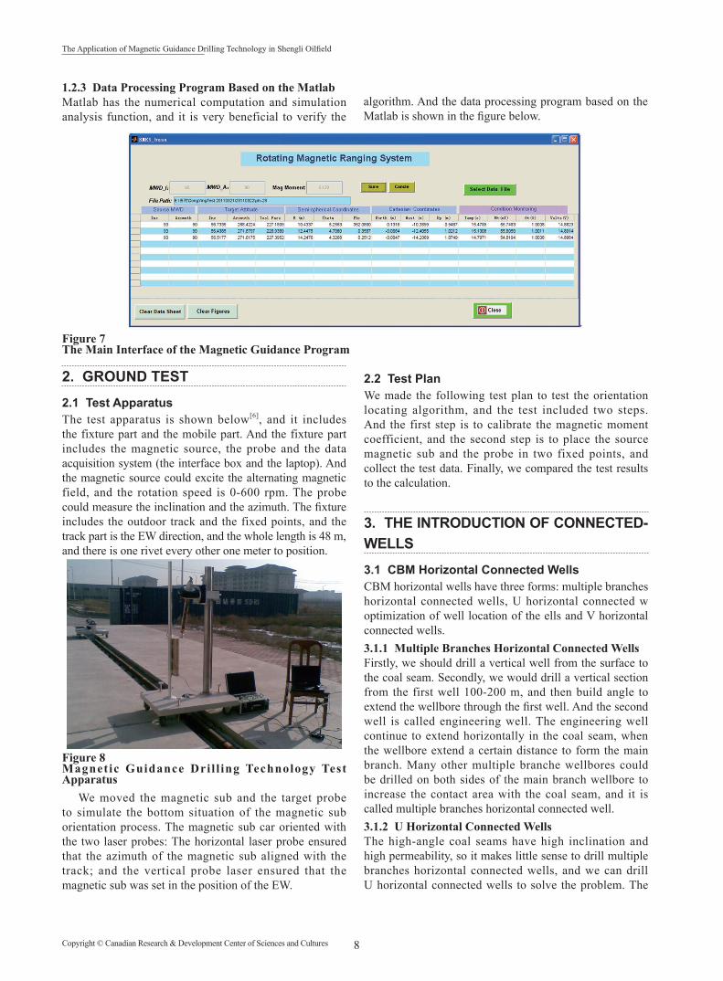
1.2.3 Data Processing Program Based on the MatlabMatlab has the numerical computation and simulation analysis function, and it is very beneficial to verify the
algorithm. And the data processing program based on the Matlab is shown in the figure below.
Figure 7The Main Interface of the Magnetic Guidance Program
2. GROUND TEST
2.1 Test ApparatusThe test apparatus is shown below[6], and it includes the fixture part and the mobile part. And the fixture part includes the magnetic source, the probe and the data acquisition system (the interface box and the laptop). And the magnetic source could excite the alternating magnetic field, and the rotation speed is 0-600 rpm. The probe could measure the inclination and the azimuth. The fixture includes the outdoor track and the fixed points, and the track part is the EW direction, and the whole length is 48 m, and there is one rivet every other one meter to position.
Figure 8Magnetic Guidance Dril l ing Technology Test Apparatus
We moved the magnetic sub and the target probe to simulate the bottom situation of the magnetic sub orientation process. The magnetic sub car oriented with the two laser probes: The horizontal laser probe ensured that the azimuth of the magnetic sub aligned with the track; and the vertical probe laser ensured that the magnetic sub was set in the position of the EW.
2.2 Test PlanWe made the following test plan to test the orientation locating algorithm, and the test included two steps. And the first step is to calibrate the magnetic moment coefficient, and the second step is to place the source magnetic sub and the probe in two fixed points, and collect the test data. Finally, we compared the test results to the calculation.
3. THE INTRODUCTION OF CONNECTED-WELLS
3.1 CBM Horizontal Connected Wells CBM horizontal wells have three forms: multiple branches horizontal connected wells, U horizontal connected w optimization of well location of the ells and V horizontal connected wells.3.1.1 Multiple Branches Horizontal Connected WellsFirstly, we should drill a vertical well from the surface to the coal seam. Secondly, we would drill a vertical section from the first well 100-200 m, and then build angle to extend the wellbore through the first well. And the second well is called engineering well. The engineering well continue to extend horizontally in the coal seam, when the wellbore extend a certain distance to form the main branch. Many other multiple branche wellbores could be drilled on both sides of the main branch wellbore to increase the contact area with the coal seam, and it is called multiple branches horizontal connected well.3.1.2 U Horizontal Connected WellsThe high-angle coal seams have high inclination and high permeability, so it makes little sense to drill multiple branches horizontal connected wells, and we can drill U horizontal connected wells to solve the problem. The

9 Copyright © Canadian Research & Development Center of Sciences and Cultures
CAO Xiangfeng; LIU Qinglong (2015). Advances in Petroleum Exploration and Development, 10(1), 5-10
horizontal section of U horizontal connected wells extend from the high end to low end of the tendency of coal seam, so U horizontal connected wells make full use of the advantage of gravity of the coal seam water, and this kind of well is advantageous to the drainage. 3.1.3 V Horizontal Connected WellsAccording to the characters of the coal-bearing strata of the Huolin River basin, the intended coal-bearing strata of this basin is lower group of Huolin River of the lower range of the cretaceous system. Huo 1 well block was the target area, and the R0 was 0.3%-0.4%, the depth was 900 m, one of the largest thick single layer is 20 m, reservoir pressure gradient of the reservoir is 1.08 MPa/100 m, the permeability is 0.91×10⁻³ µm2, the density is 1.5 g/cm3, the dip angle is 12°-15°. We designed the V horizontal connected wells in the condition of the coal seam, and the most important point was the connected point of the vertical where we chose. And we can divide the well into three parts as the target range of the horizontal well and vertical well connected.
3.2 Well Location Optimizing of Horizontal Wells in Pairs for the Super Heavy RecoveryHorizontal wells in pairs are mainly applied in the steam assisted gravity drainage (SAGD) petroleum engineering of the heavy oil. SAGD requests that one horizontal well must be drilled first above the oil-water interface near the bottom of the oil column, and the steam was injected through the second upper horizontal well which was parallel to the first horizontal well, so the steam chamber above the production well was formed. And the steam and the oil were output together from the production well.
3.3 Working Process of Connected Wells(a) The quality of the vertical well affects the difficulty
of the horizontal connected wells. Optimizing the assembly and the drilling parameters, we should use the deviation control technology to control the inclination of the well. After the electric logging, fiber glass casing was run in. The operator used the hole enlarger to enlarge the borehole, the enlarging diameter need to be more than 500 mm.
(b) In the process of drilling the horizontal section, the operator should control the well trajectory along the drilling design, and use the LWD to ensure the target hitting quality.
(c) We should filter the magnetic signal data with the well trajectory data to calculate the distance between the bit to the target, the deviation between the bit to the target and the deviation of the vertical depth to achieve the precise connection.
3.4 Working Process of Horizontal Wells in Pairs(a) According to the drilling design and the geological design, we should check the location of the wells. And the distance between the two wells is 15 m.
(b) The first well is upper production well, and the second well is lower injection well. The first well is drilled with LWD, and then cased.
(c) Through the crab locomotive, the magnetic guidance instrument is put into the A target of the first well.
(d) With the crab, the data is transferred to the surface, then the operator controls the well trajectory of the second well. The instrument is put into 30 m after one pillar is drilled, and this process is repeated when the second well is drilled to the design depth.
4. FIELD TEST
4.1 Well DFS-C04-H2 (a) We had mastered the connected well drilling
technology through DFS-C04-H2 well and DFS-C04-V1 field test. And we must control the inclination of the vertical well, and the diameter of the borehole should be not less than 500 mm.
(b) The horizontal well should be drilled along the design.
(c) We utilized the NMDP to decrease the magnetic interference.
(d) We mastered the magnetic guidance drilling apparatus and the software to direct the directional engineer to control the well trajectory accurately.
Figure 9DFS-C04-H2 Well and DFS-C04-V1 Well Connected Successfully4.2 Well ZM 1 The magnetic guidance drilling technology was further perfect through two field tests. And the magnetic guidance apparatus could calculate within 82 m, and the magnetic field tend to be more standard sine wave signal waveform, and the working performance was good.
4.3 Well SN06 (a) The first time: The magnetic interference was serious
when the distance was 74.34 m, and the signal was well when the distance was 60 m. And the azimuth deviation is 9º when the distance is 50 m, and the engineer decided to lift 100 m to sidetrack.

10Copyright © Canadian Research & Development Center of Sciences and Cultures
The Application of Magnetic Guidance Drilling Technology in Shengli Oilfield
Figure 10The Signal Interference Was Bad When the Distance Was 74.34 m
(b) The second time: The signal was well when the distance was 48.9 m. And the azimuth deviation is 2.31º.
This run failed to connect, so the engineer decided to lift 50 m to sidetrack.
Figure 11The Signal Was Well When the Distance Was 27.69 m
(c) The third time: The two wells were connected successfully.
CONCLUSIONThrough the research of this projection, we have realized the working principle of the magnetic instrument and connected wells. This technology supplies the convincing supports for dual horizontal wells drill horizontal wells in pairs for high oil reservoir.
Through the field tests, we could found the data acquisition circuit could satisfy the dynamic low frequency alternating magnetic field range of 10 uV - 1 V. And the hardware and software were improved with the test on the ground to reach the indexes stipulated in the project. The AOM-35A probe could detect the signal within 60-70 m, and the system could orient accurately within 50 m.
REFERENCES[1] Lin, J., Song, C. H., & Luo, Y. H., & Liu, L. (2009).
Horizontal drilling technology of SAGD. Xinjiang Petroleum and Gas, 5(3), 56-61.
[2] Qian, Z. W., Jiang, Z. Q., & Wu, H. L. (2011). Relief well technology basic on RMRS. Coal Mine Safty, 42(2), 52-54.
[3] Diao, B. B., & Gao, D. L. (2011). Solenoid while drilling distance guidance system. Acta Petrolei Sinica, 32(6), 1061-1066.
[4] Xu, Y. L., Ma, F. Q., & Feng, G. T. (2012). Magneti guidance drilling technology curr cent t situation and development. Oil Drilling & Production Technology, 35(2), 35-37.
[5] Zong, Y. B., Zhang, J., & Shi, X. F. (2011). A high-precision guidance method of wellbore trajectory based on the rotary magnetic dipole. Atca Petrolei Sinica, 32(2), 335-339.
[6] Tian, Y., & Wang, C. L. (2011). Rotating magnetic guidance method and its experiments for measurement while drilling. Elettronic Measurement Technology, 34(10), 4-7.