the apollo intelligent meter series - red lion product manual_0.pdfthe intelligent meter for process...
TRANSCRIPT

THE APOLLO INTELLIGENT METER SERIES
MODEL IMP INSTRUCTION MANUAL

INTRODUCTIONThe Intelligent Meter for Process Inputs (IMP) is another unit in our
multi-purpose series of industrial control products that is field-programmable for solving various applications. This series of products is built around the concept that the end user has the capability to program different personalities and functions into the unit in order to adapt to different indication and control requirements.
The Intelligent Process Meter, which you have purchased, has the same high quality workmanship and advanced technological capabilities that have made Red Lion Controls the leader in today's industrial market.
Red Lion Controls has a complete line of industrial indication and control equipment, and we look forward to being of service to you now and in the future.
CAUTION: Risk of Danger. Read complete instructions prior to
installation and operation of the unit.
CAUTION: Risk of electric shock.
Table of Contents
SAFETY INFORMATION · · · · · · · · · · · · · · · · · · · · · · · · · · · · · · · · · · · · · · · · · · · · · · · · · · · · · · · · · · · · · · · 1Safety Summary · · · · · · · · · · · · · · · · · · · · · · · · · · · · · · · · · · · · · · · · · · · · · · · · · · · · · · · · · · · · · · · · · · · 1Definition Of Terms · · · · · · · · · · · · · · · · · · · · · · · · · · · · · · · · · · · · · · · · · · · · · · · · · · · · · · · · · · · · · · · · · 1
GENERAL DESCRIPTION· · · · · · · · · · · · · · · · · · · · · · · · · · · · · · · · · · · · · · · · · · · · · · · · · · · · · · · · · · · · · · 2Theory Of Operation · · · · · · · · · · · · · · · · · · · · · · · · · · · · · · · · · · · · · · · · · · · · · · · · · · · · · · · · · · · · · · · · 2Block Diagram · · · · · · · · · · · · · · · · · · · · · · · · · · · · · · · · · · · · · · · · · · · · · · · · · · · · · · · · · · · · · · · · · · · · · 3
PROGRAMMING & OPERATING THE IMP· · · · · · · · · · · · · · · · · · · · · · · · · · · · · · · · · · · · · · · · · · · · · · · · 4Programming the IMP · · · · · · · · · · · · · · · · · · · · · · · · · · · · · · · · · · · · · · · · · · · · · · · · · · · · · · · · · · · · · · · 4Module #1 - Scale By Signal Level Method · · · · · · · · · · · · · · · · · · · · · · · · · · · · · · · · · · · · · · · · · · · · · 6Module #2 - Scale By Key-In Method · · · · · · · · · · · · · · · · · · · · · · · · · · · · · · · · · · · · · · · · · · · · · · · · · · 8Module #3 - Program Functions Accessible W/ Front Panel Lockout · · · · · · · · · · · · · · · · · · · · · · · 10Module #4 - Programming Digital Filter and Remote Input · · · · · · · · · · · · · · · · · · · · · · · · · · · · · · · · 12Module #5 - Program Totalizer/Integrator · · · · · · · · · · · · · · · · · · · · · · · · · · · · · · · · · · · · · · · · · · · · · · 14Module #6 - Program Alarm/Setpoint · · · · · · · · · · · · · · · · · · · · · · · · · · · · · · · · · · · · · · · · · · · · · · · · · 15Module #7 - Program Serial Communications · · · · · · · · · · · · · · · · · · · · · · · · · · · · · · · · · · · · · · · · · · 17Module #8 - Program Re-Transmitted Analog Output · · · · · · · · · · · · · · · · · · · · · · · · · · · · · · · · · · · · 18Module #9 - Service Operations · · · · · · · · · · · · · · · · · · · · · · · · · · · · · · · · · · · · · · · · · · · · · · · · · · · · · 19Operating the IMP · · · · · · · · · · · · · · · · · · · · · · · · · · · · · · · · · · · · · · · · · · · · · · · · · · · · · · · · · · · · · · · · · 20Quick Programming · · · · · · · · · · · · · · · · · · · · · · · · · · · · · · · · · · · · · · · · · · · · · · · · · · · · · · · · · · · · · · · 20Factory Configuration · · · · · · · · · · · · · · · · · · · · · · · · · · · · · · · · · · · · · · · · · · · · · · · · · · · · · · · · · · · · · · 21Programming Example · · · · · · · · · · · · · · · · · · · · · · · · · · · · · · · · · · · · · · · · · · · · · · · · · · · · · · · · · · · · · 22Pressure Monitoring Example · · · · · · · · · · · · · · · · · · · · · · · · · · · · · · · · · · · · · · · · · · · · · · · · · · · · · · · 23
EXCITATION (Optional) · · · · · · · · · · · · · · · · · · · · · · · · · · · · · · · · · · · · · · · · · · · · · · · · · · · · · · · · · · · · · · 24
TOTALIZER/LINEARIZER/PEAK/VALLEY/TARE (Optional) · · · · · · · · · · · · · · · · · · · · · · · · · · · · · · · · 24Totalizer · · · · · · · · · · · · · · · · · · · · · · · · · · · · · · · · · · · · · · · · · · · · · · · · · · · · · · · · · · · · · · · · · · · · · · · · · 24Totalizer Example · · · · · · · · · · · · · · · · · · · · · · · · · · · · · · · · · · · · · · · · · · · · · · · · · · · · · · · · · · · · · · · · · 24Linearizer · · · · · · · · · · · · · · · · · · · · · · · · · · · · · · · · · · · · · · · · · · · · · · · · · · · · · · · · · · · · · · · · · · · · · · · · 25Peak/Valley · · · · · · · · · · · · · · · · · · · · · · · · · · · · · · · · · · · · · · · · · · · · · · · · · · · · · · · · · · · · · · · · · · · · · · 27Tare · · · · · · · · · · · · · · · · · · · · · · · · · · · · · · · · · · · · · · · · · · · · · · · · · · · · · · · · · · · · · · · · · · · · · · · · · · · · 27
ALARMS (Optional) · · · · · · · · · · · · · · · · · · · · · · · · · · · · · · · · · · · · · · · · · · · · · · · · · · · · · · · · · · · · · · · · · 28
20 mA CURRENT LOOP SERIAL COMMUNICATIONS (Optional) · · · · · · · · · · · · · · · · · · · · · · · · · · · 29General Description · · · · · · · · · · · · · · · · · · · · · · · · · · · · · · · · · · · · · · · · · · · · · · · · · · · · · · · · · · · · · · · 29Communication Format · · · · · · · · · · · · · · · · · · · · · · · · · · · · · · · · · · · · · · · · · · · · · · · · · · · · · · · · · · · · 29
-i-

Sending Commands to the IMP · · · · · · · · · · · · · · · · · · · · · · · · · · · · · · · · · · · · · · · · · · · · · · · · · 30Receiving Data from the IMP· · · · · · · · · · · · · · · · · · · · · · · · · · · · · · · · · · · · · · · · · · · · · · · · · · · 32
CURRENT LOOP INSTALLATION · · · · · · · · · · · · · · · · · · · · · · · · · · · · · · · · · · · · · · · · · · · · · · · · · 34Wiring Connections · · · · · · · · · · · · · · · · · · · · · · · · · · · · · · · · · · · · · · · · · · · · · · · · · · · · · · · · · · 34Serial Terminal Descriptions · · · · · · · · · · · · · · · · · · · · · · · · · · · · · · · · · · · · · · · · · · · · · · · · · · · 34Serial Communications Example · · · · · · · · · · · · · · · · · · · · · · · · · · · · · · · · · · · · · · · · · · · · · · · · 35Process Controlling System · · · · · · · · · · · · · · · · · · · · · · · · · · · · · · · · · · · · · · · · · · · · · · · · · · · 35
RE-TRANSMITTED ANALOG OUTPUT (Optional) · · · · · · · · · · · · · · · · · · · · · · · · · · · · · · · · · · · · 36Analog Output Calibration · · · · · · · · · · · · · · · · · · · · · · · · · · · · · · · · · · · · · · · · · · · · · · · · · · · · 37
APPENDIX “A” - INSTALLATION & CONNECTIONS · · · · · · · · · · · · · · · · · · · · · · · · · · · · · · · · · 38Installation Environment · · · · · · · · · · · · · · · · · · · · · · · · · · · · · · · · · · · · · · · · · · · · · · · · · · · · · · 38
Panel Installation · · · · · · · · · · · · · · · · · · · · · · · · · · · · · · · · · · · · · · · · · · · · · · · · · · · · · · · · · 38Select AC Power (115/230 VAC) · · · · · · · · · · · · · · · · · · · · · · · · · · · · · · · · · · · · · · · · · · · · · · · · 38EMC Installation Guidelines · · · · · · · · · · · · · · · · · · · · · · · · · · · · · · · · · · · · · · · · · · · · · · · · · · · 39Wiring Connections · · · · · · · · · · · · · · · · · · · · · · · · · · · · · · · · · · · · · · · · · · · · · · · · · · · · · · · · · · 40
Power Wiring · · · · · · · · · · · · · · · · · · · · · · · · · · · · · · · · · · · · · · · · · · · · · · · · · · · · · · · · · · · · 40User Input Wiring · · · · · · · · · · · · · · · · · · · · · · · · · · · · · · · · · · · · · · · · · · · · · · · · · · · · · · · · · 40
Output Wiring · · · · · · · · · · · · · · · · · · · · · · · · · · · · · · · · · · · · · · · · · · · · · · · · · · · · · · · · · · · · · · 40Relay Connections · · · · · · · · · · · · · · · · · · · · · · · · · · · · · · · · · · · · · · · · · · · · · · · · · · · · · · · · · · 40
Signal Wiring · · · · · · · · · · · · · · · · · · · · · · · · · · · · · · · · · · · · · · · · · · · · · · · · · · · · · · · · · · · · 41
APPENDIX “B” - SPECIFICATIONS AND DIMENSIONS · · · · · · · · · · · · · · · · · · · · · · · · · · · · · · · · 42APPENDIX “C” - TROUBLESHOOTING GUIDE · · · · · · · · · · · · · · · · · · · · · · · · · · · · · · · · · · · · · · 44APPENDIX “D” - PROGRAMMABLE FUNCTIONS · · · · · · · · · · · · · · · · · · · · · · · · · · · · · · · · · · · · 45APPENDIX “E” - USERS PROGRAMMING VALUES CHART · · · · · · · · · · · · · · · · · · · · · · · · · · · · 47APPENDIX “F” - ORDERING INFORMATION · · · · · · · · · · · · · · · · · · · · · · · · · · · · · · · · · · · · · · · · 49
-ii-

SAFETY INFORMATION
SAFETY SUMMARY
All safety related regulations, local codes and instructions that appear in themanual or on equipment must be observed to ensure personal safety and toprevent damage to either the instrument or equipment connected to it. Ifequipment is used in a manner not specified by the manufacturer, the protectionprovided by the equipment may be impaired.
Do not use the IMP to directly command motors valves, or other actuators notequipped with safeguards. To do so, can be potentially harmful to persons orequipment in the event of a fault to the unit.
DEFINITION OF TERMS
INSTALLATION CATEGORY (overvoltage category) I:Signal level, special equipment or parts of equipment, telecommunication,electronic, etc. with smaller transient overvoltages than Installation Category(overvoltage category) II.
INSTALLATION CATEGORY (overvoltage category) II:Local level, appliances, portable equipment, etc. with smaller transientovervoltages than Installation Category (overvoltage category) III.
-1-
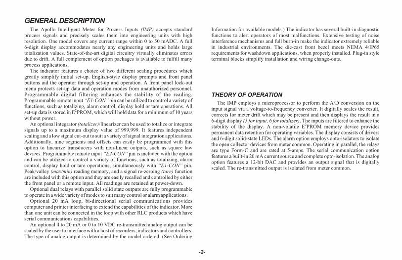
GENERAL DESCRIPTIONThe Apollo Intelligent Meter for Process Inputs (IMP) accepts standard
process signals and precisely scales them into engineering units with highresolution. One model covers any current range within 0 to 50 mADC. A full6-digit display accommodates nearly any engineering units and holds largetotalization values. State-of-the-art digital circuitry virtually eliminates errorsdue to drift. A full complement of option packages is available to fulfill manyprocess applications.
The indicator features a choice of two different scaling procedures whichgreatly simplify initial set-up. English-style display prompts and front panelbuttons aid the operator through set-up and operation. A front panel lock-outmenu protects set-up data and operation modes from unauthorized personnel.Programmable digital filtering enhances the stability of the reading.Programmable remote input “E1-CON” pin can be utilized to control a variety offunctions, such as totalizing, alarm control, display hold or tare operations. Allset-up data is stored in E2PROM, which will hold data for a minimum of 10 yearswithout power.
An optional integrator (totalizer)/linearizer can be used to totalize or integratesignals up to a maximum display value of 999,999. It features independentscaling and a low signal cut-out to suit a variety of signal integration applications.Additionally, nine segments and offsets can easily be programmed with thisoption to linearize transducers with non-linear outputs, such as square lawdevices. Programmable remote input “E2-CON” pin is included with the optionand can be utilized to control a variety of functions, such as totalizing, alarmcontrol, display hold or tare operations, simultaneously with “E1-CON” pin.Peak/valley (max/min) reading memory, and a signal re-zeroing (tare) functionare included with this option and they are easily recalled and controlled by eitherthe front panel or a remote input. All readings are retained at power-down.
Optional dual relays with parallel solid state outputs are fully programmableto operate in a wide variety of modes to suit many control or alarm applications.
Optional 20 mA loop, bi-directional serial communications providescomputer and printer interfacing to extend the capabilities of the indicator. Morethan one unit can be connected in the loop with other RLC products which haveserial communications capabilities.
An optional 4 to 20 mA or 0 to 10 VDC re-transmitted analog output can bescaled by the user to interface with a host of recorders, indicators and controllers.The type of analog output is determined by the model ordered. (See Ordering
Information for available models.) The indicator has several built-in diagnosticfunctions to alert operators of most malfunctions. Extensive testing of noiseinterference mechanisms and full burn-in make the indicator extremely reliablein industrial environments. The die-cast front bezel meets NEMA 4/IP65requirements for washdown applications, when properly installed. Plug-in styleterminal blocks simplify installation and wiring change-outs.
THEORY OF OPERATION
The IMP employs a microprocessor to perform the A/D conversion on theinput signal via a voltage-to-frequency converter. It digitally scales the result,corrects for meter drift which may be present and then displays the result in a6-digit display (5 for input, 6 for totalizer). The inputs are filtered to enhance thestability of the display. A non-volatile E2PROM memory device providespermanent data retention for operating variables. The display consists of driversand 6-digit solid-state LEDs. The alarm option employs opto-isolators to isolatethe open collector devices from meter common. Operating in parallel, the relaysare type Form-C and are rated at 5-amps. The serial communication optionfeatures a built-in 20 mA current source and complete opto-isolation. The analogoption features a 12-bit DAC and provides an output signal that is digitallyscaled. The re-transmitted output is isolated from meter common.
-2-
-3-
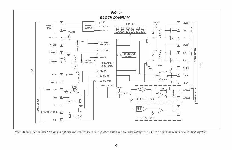
Note: Analog, Serial, and SNK output options are isolated from the signal common at a working voltage of 50 V. The commons should NOT be tied together.
FIG. 1:
BLOCK DIAGRAM
PROGRAMMING & OPERATING THE IMP
PROGRAMMING THE IMP
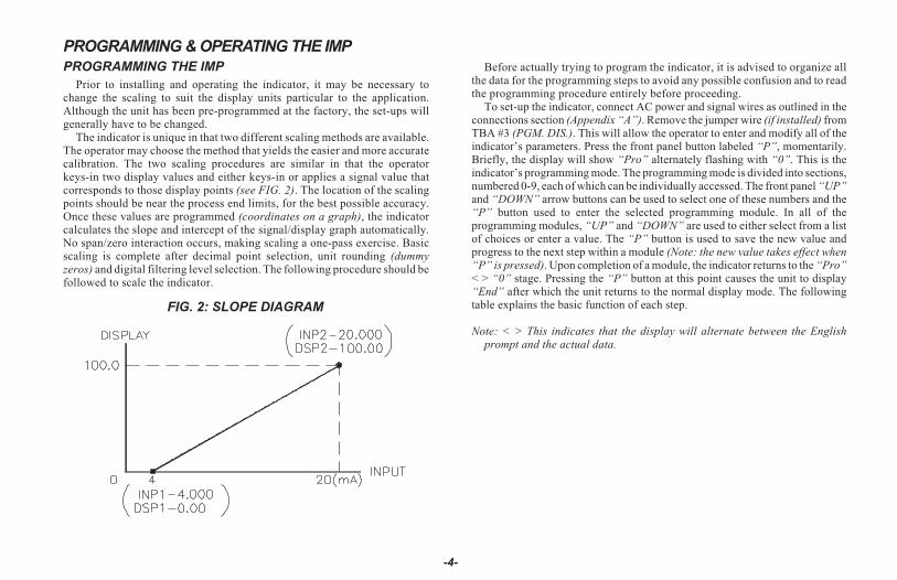
Prior to installing and operating the indicator, it may be necessary tochange the scaling to suit the display units particular to the application.Although the unit has been pre-programmed at the factory, the set-ups willgenerally have to be changed.
The indicator is unique in that two different scaling methods are available.The operator may choose the method that yields the easier and more accuratecalibration. The two scaling procedures are similar in that the operatorkeys-in two display values and either keys-in or applies a signal value thatcorresponds to those display points (see FIG. 2). The location of the scalingpoints should be near the process end limits, for the best possible accuracy.Once these values are programmed (coordinates on a graph), the indicatorcalculates the slope and intercept of the signal/display graph automatically.No span/zero interaction occurs, making scaling a one-pass exercise. Basicscaling is complete after decimal point selection, unit rounding (dummyzeros) and digital filtering level selection. The following procedure should befollowed to scale the indicator.
Before actually trying to program the indicator, it is advised to organize allthe data for the programming steps to avoid any possible confusion and to readthe programming procedure entirely before proceeding.
To set-up the indicator, connect AC power and signal wires as outlined in theconnections section (Appendix “A”). Remove the jumper wire (if installed) fromTBA #3 (PGM. DIS.). This will allow the operator to enter and modify all of theindicator’s parameters. Press the front panel button labeled “P”, momentarily.Briefly, the display will show “Pro” alternately flashing with “0”. This is theindicator’s programming mode. The programming mode is divided into sections,numbered 0-9, each of which can be individually accessed. The front panel “UP”and “DOWN” arrow buttons can be used to select one of these numbers and the“P” button used to enter the selected programming module. In all of theprogramming modules, “UP” and “DOWN” are used to either select from a listof choices or enter a value. The “P” button is used to save the new value andprogress to the next step within a module (Note: the new value takes effect when“P” is pressed). Upon completion of a module, the indicator returns to the “Pro”< > “0” stage. Pressing the “P” button at this point causes the unit to display“End” after which the unit returns to the normal display mode. The followingtable explains the basic function of each step.
Note: < > This indicates that the display will alternate between the Englishprompt and the actual data.
-4-
FIG. 2: SLOPE DIAGRAM

DISPLAY RESULT OF “P” BUTTON
“Pro” < > “0” Causes the indicator to return to normal display mode. Anychanges to set-up data are permanently stored in theE2PROM.
“Pro” < > “1” Entry into this module allows the user to select the decimalpoint position, unit rounding and scaling by the method ofapplying the actual signal levels to the indicator thatcorrespond to the programmed display values. Use thismethod when the transducer is connected to the process andthe process can be brought to known levels (ie. weight,flow, pressure, etc.). Alternately, a precision signal sourcemay be substituted to simulate the transducer. A secondmethod is available in Pro 2.
“Pro” < > “2” Entry into this module allows the user to select the decimalpoint position and unit rounding, as in Pro 1, but the methodof scaling differs in that the user keys in signal levels insteadof applying signals to the indicator. Use this method whenthe signal transducer is pre-calibrated with known displayvalues at known signal levels. An alternate method isavailable in Pro 1.
“Pro” < > “3” Module #3 allows the user to program what can be accessedfrom the front panel when the PGM. DIS. (Program Disable,TBA #3) pin is connected to common. This feature protectscritical set-up data from accidental modification whileallowing access to setpoints and other functions. The frontpanel lock-out menu (quick programming) includes setpointmodification, totalizer resetting, and peak/valley resetting.
Note: The term “Quick Programming” is used to refer tothe ability to change the information that can beaccessed from the front panel when the “PGM. DIS.”terminal is connected to “COMM.”.
DISPLAY RESULT OF “P” BUTTON
“Pro” < > “4” Module #4 programs the digital filtering level and thefunction of the remote input ”E1-CON" pin (TBA #4), and,if the totalizer option is installed, the remote input“E2-CON” pin (TBA #8). The functions of the remote E1and E2 pins are the same and include display hold, peak/valley modes, totalizer reset, alarm reset, signal re-zero(tare), reading synchronization or print request.
“Pro” < > “5” This module sets the time base, scale factor and low signaldisable function for the optional totalizer/ integrator.
“Pro” < > “6” This module allows programming for the basicconfiguration of the alarm option. The programmingincludes HI/LO acting, tracking, alarm display, latched orauto-rese t , ass ignment to ei ther s ignal orintegrator/totalizer, and alarm and hysteresis values.
“Pro” < > “7” Module #7 is the serial communication parameterprogramming. Baud rate, unit address, print requestfunction and condensed prints are all programmable.
“Pro” < > “8” This module allows digital scaling of the retransmittedanalog output. Display values that correspond to 4 mA or 0VDC and 20 mA or 10 VDC are keyed-in to scale the outputand it may be assigned to either the signal or thetotalizer/integrator.
“Pro” < > “9” This module is the service operations sequence and is notnormally accessed by the user. This step re-calibrates thebasic input and is used to compensate for long-term drift.Execution of this module should be done by technicianswith the proper equipment in accordance with amaintenance plan of yearly recalibrations. A code numberentry step is used to protect from inadvertent entries. Also,there is a number of other access codes which provide testand set-up changes as an aid in troubleshooting.
-5-
MODULE #1 - SCALE BY SIGNAL LEVEL METHOD
PROGRAM DECIMAL POINT POSITION
Select the desired decimal point position of the scaled display by pressingeither the “Up” or “Down” button.
Note: Whatever decimal point is selected will appear in succeedingprogramming steps. Also, the “P” button must be pressed after each step to enterthe desired data and to proceed to the next step.
“ dECPNt” < > “0”“0.0”“0.00”“0.000”“0.0000”
PROGRAM ROUNDING INCREMENT AND RIGHT HANDDUMMY ZEROS
Rounding values other than one cause the scaled number to ‘round’ to thenearest rounding increment selected (ie. rounding of ‘5’ causes ‘122’ to round to‘120’ and ‘123’ to round to ‘125’). If the process is inherently jittery, the displayvalue may be rounded to a higher value than one. If the range of the processexceeds the required resolution, (ex. 0-10,000 PSI, but only 10 PSI resolutionrequired), a rounding increment of 10 will effectively make the display morestable. This programming step is usually used in conjunction with programmabledigital filtering (Pro 4) to help stabilize display readings. (If display stabilityappears to be a problem and the sacrifice in display resolution is unacceptable,program higher levels of digital filtering or increase the level of processdampening.) Rounding increments of 10, 20, 50, and 100 may also be used to add“dummy zeros” to the scaled readings, as desired.
“round”< > “1”“2”“5”“10”“20”“50”“100”
At this stage a choice of either return to “Pro 0” or continue with scaling of thedisplay is offered.
“SCALE” < > “yES”“NO”
If “yES” was selected for the previous step, the scaling procedure is started. Inorder to scale the indicator, by either method, two signal level values and twodisplay values that correspond to the signal values must be known. These fourvalues are then used to complete the scaling operation. An example of asignal-display pair is listed below:
3.000 PSI @ 4.000 mA AND 15.000 PSI @ 20.000 mAScaling point #1 Scaling point #2
Note that reverse acting indication can be accomplished by either reversingthe two signal points or the display value points, but not both. If both are reversed,then forward (normal) acting indication will occur. In either case do not reversethe input wires to correct the action because the indicator is designed for positivesignals only. With this scaling procedure, the display values are keyed in andsignal values are applied to the indicator by either a signal simulator or the actualsignal source.
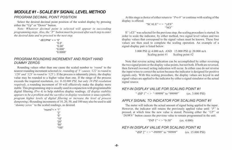
KEY-IN DISPLAY VALUE FOR SCALING POINT #1
“ dSP 1” < > “-99999” to “99999” (ex. 3.000 PSI)
APPLY SIGNAL TO INDICATOR FOR SCALING POINT #1
The meter will indicate the actual amount of signal being applied to the input .However, the indicator still retains the previously applied value until “P” ispressed, at which time the new value is stored. Pressing either the “UP” or“DOWN” button causes the previous value to remain programmed in the unit.
“INP 1” < > “0-50” (ex. 4.000)
KEY-IN DISPLAY VALUE FOR SCALING POINT #2
“dSP 2” < > “-99999” to “99999” (ex. 15.000 PSI)
-6-
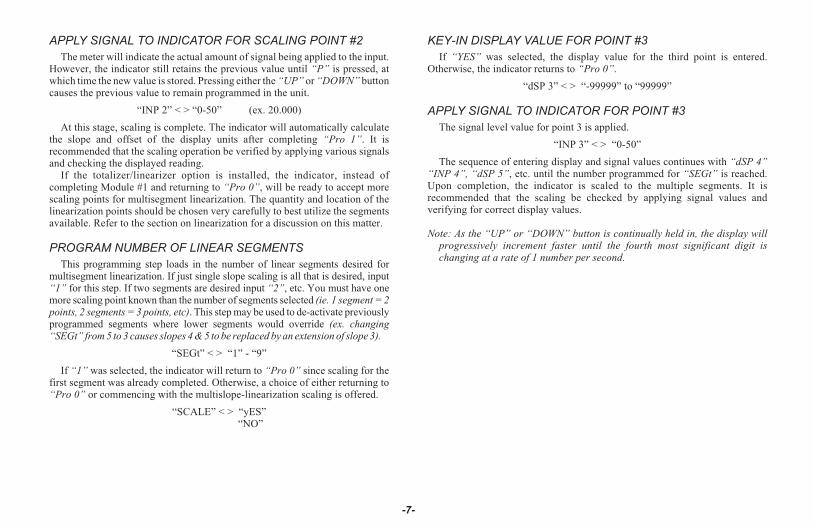
APPLY SIGNAL TO INDICATOR FOR SCALING POINT #2
The meter will indicate the actual amount of signal being applied to the input.However, the indicator still retains the previous value until “P” is pressed, atwhich time the new value is stored. Pressing either the “UP” or “DOWN” buttoncauses the previous value to remain programmed in the unit.
“INP 2” < > “0-50” (ex. 20.000)
At this stage, scaling is complete. The indicator will automatically calculatethe slope and offset of the display units after completing “Pro 1”. It isrecommended that the scaling operation be verified by applying various signalsand checking the displayed reading.
If the totalizer/linearizer option is installed, the indicator, instead ofcompleting Module #1 and returning to “Pro 0”, will be ready to accept morescaling points for multisegment linearization. The quantity and location of thelinearization points should be chosen very carefully to best utilize the segmentsavailable. Refer to the section on linearization for a discussion on this matter.
PROGRAM NUMBER OF LINEAR SEGMENTS
This programming step loads in the number of linear segments desired formultisegment linearization. If just single slope scaling is all that is desired, input“1” for this step. If two segments are desired input “2”, etc. You must have onemore scaling point known than the number of segments selected (ie. 1 segment = 2points, 2 segments = 3 points, etc). This step may be used to de-activate previouslyprogrammed segments where lower segments would override (ex. changing“SEGt” from 5 to 3 causes slopes 4 & 5 to be replaced by an extension of slope 3).
“SEGt” < > “1” - “9”
If “1” was selected, the indicator will return to “Pro 0” since scaling for thefirst segment was already completed. Otherwise, a choice of either returning to“Pro 0” or commencing with the multislope-linearization scaling is offered.
“SCALE” < > “yES”“NO”
KEY-IN DISPLAY VALUE FOR POINT #3
If “YES” was selected, the display value for the third point is entered.Otherwise, the indicator returns to “Pro 0”.
“dSP 3” < > “-99999” to “99999”
APPLY SIGNAL TO INDICATOR FOR POINT #3
The signal level value for point 3 is applied.
“INP 3” < > “0-50”
The sequence of entering display and signal values continues with “dSP 4”“INP 4”, “dSP 5”, etc. until the number programmed for “SEGt” is reached.Upon completion, the indicator is scaled to the multiple segments. It isrecommended that the scaling be checked by applying signal values andverifying for correct display values.
Note: As the “UP” or “DOWN” button is continually held in, the display willprogressively increment faster until the fourth most significant digit ischanging at a rate of 1 number per second.
-7-

MODULE #2 - SCALE BY KEY-IN METHOD
PROGRAM DECIMAL POINT POSITION
Select the desired decimal point position of the scaled display by pressingeither the “Up” or “Down” button.
Note: Whatever decimal point is selected will appear in succeedingprogramming steps. Also, the “P” button must be pressed after each step to enterthe desired data and to proceed to the next step.
“ dECPNt” < > “0”“0.0”“0.00”“0.000”“0.0000”
PROGRAM ROUNDING INCREMENT AND RIGHT HANDDUMMY ZEROS
Rounding values other than one cause the scaled number to ‘round’ to thenearest rounding increment selected (ie. rounding of ‘5’ causes ‘122’ to round to‘120’ and ‘123’ to round to ‘125’). If the process is inherently jittery, the displayvalue may be rounded to a higher value than one. This will allow the display to beeasier to read. If the range of the process exceeds the required resolution, (ex.0-10,000 PSI, but only 10 PSI resolution required), a rounding increment of 10 willeffectively make the display more stable. This programming step is usually used inconjunction with programmable digital filtering (Pro 4) to help stabilize displayreadings. (If display stability appears to be a problem and the sacrifice in displayresolution is unacceptable, program higher levels of digital filtering or increasethe level of process dampening.) Rounding increments of 10, 20, 50, and, 100 mayalso be used to add “dummy zeros” to the scaled readings, as desired.
“round”< > “1”“2”“5”“10”“20”“50”“100”
At this stage a choice of either return to “Pro 0” or continue with scaling of thedisplay is offered.
“SCALE” < > “yES”“NO”
If “YES” was selected for the previous step, the scaling procedure is started. Inorder to scale the indicator, two signal level values and two display values thatcorrespond to the signal values must be known. These four values are directlyentered into the indicator. An example of a signal-display pair is listed below:
3.000 PSI @ 4.000 mA AND 15.000 PSI @ 20.000 mAScaling point #1 Scaling point #2
Note that reverse acting indication can be accomplished by either reversingthe two signal points or the display value points, but not both. If both are reversed,then forward (normal) acting indication will occur. In either case, do not reversethe input signal wires because the indicator was designed to accept positivesignals only. With this scaling procedure, both the display values and signalvalues are keyed in.
KEY-IN DISPLAY VALUE FOR SCALING POINT #1
“dSP 1” < > “-99999” to “99999” (ex. 3.000 PSI)
KEY-IN SIGNAL VALUE FOR SCALING POINT #1
“INP 1” < > “0-50” (ex. 4.000)
KEY-IN DISPLAY VALUE FOR SCALING POINT #2
“dSP 2” < > “-99999” to “99999” (ex. 15.000 PSI)
-8-

KEY-IN SIGNAL VALUE FOR SCALING POINT #2
“INP 2” < > “0-50” (ex. 20.000)
At this point, scaling is complete. The indicator will automatically calculate theslope and offset of the display units. It is recommended that the scaling operationbe verified by applying various signals and checking the displayed reading.
If the totalizer/linearizer option is installed, the indicator, instead ofcompleting module #1 and returning to “Pro 0”, will be ready to accept morescaling points for multisegment linearization. The quantity and location of thelinearization points should be chosen very carefully to best utilize the segmentsavailable. Refer to the section on linearization for a discussion on this matter.
PROGRAM NUMBER OF LINEAR SEGMENTS
This programming step loads in the number of linear segments desired formultisegment linearization. If just single slope scaling is all that is desired,program “1” for this step. If two segments are desired, program “2”, etc. Youmust have one more scaling point known than the number of segments selected(ie. 1 segment = 2 points, 2 segments = 3 points, etc). This step may also be usedto de-activate previously programmed segments where lower segments wouldoverride (ex. changing “SEGt” from 5 to 3 causes slopes 4 and 5 to be replacedby an extension of slope 3).
“SEGt” < > “1” - “9”
If “1” was selected, the indicator will return to “Pro 0” since scaling for thefirst slope was already completed. Otherwise, a choice of either returning to “Pro0” or commencing with the multislope-linearization scaling is offered.
“SCALE” < > “yES”“NO”
If “yes” was selected, the display value for the third point is entered.Otherwise, the indicator returns to “Pro 0”.
KEY-IN DISPLAY VALUE FOR SCALING POINT #3
“dSP 3” < > “-99999” to “99999”
KEY-IN INPUT VALUE FOR SCALING POINT #3
“INP 3” < > “0-50”
The sequence of entering display and signal values continues with “dSP 4”“INP 4”, “dSP 5”, etc. until the number programmed for “SEGt” is reached.Upon completion, the indicator is scaled to the multiple segments. It isrecommended that the scaling be checked by exiting the programming mode andapplying signal values and verifying for correct display values.
Note: As the “UP” or “DOWN” button is continually held in, the display willprogressively increment faster until the fourth most significant digit ischanging at a rate of 1 number per second.
-9-
MODULE #3 - PROGRAM FUNCTIONS ACCESSIBLE W/ FRONT PANEL LOCKOUT
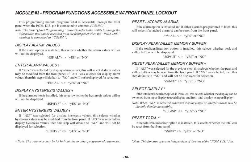
This programming module programs what is accessible through the frontpanel when the PGM. DIS. pin is connected to common (COMM.).
Note: The term “Quick Programming” is used to refer to the ability to change theinformation that can be accessed from the front panel when the “PGM. DIS.”terminal is connected to “COMM.”.
DISPLAY ALARM VALUES
If the alarm option is installed, this selects whether the alarm values will orwill not be displayed.
“dSP AL” < > “yES” or “NO”
ENTER ALARM VALUES �
If “YES” was selected for display alarm values, this will select if alarm valuesmay be modified from the front panel. If “NO” was selected for display alarmvalues, then this step will default to “NO” and will not be displayed for selection.
“ENt AL” < > “yES” or “NO”
DISPLAY HYSTERESIS VALUES �
If the alarm option is installed, this selects whether the hysteresis values will orwill not be displayed.
“dSPHYS” < > “yES” or “NO”
ENTER HYSTERESIS VALUES �
If “YES” was selected for display hysteresis values, this selects whetherhysteresis values may be modified from the front panel. If “NO” was selected fordisplay hysteresis values, then this step will default to “NO” and will not bedisplayed for selection.
“ENtHYS” < > “yES” or “NO”
� Note: This sequence may be locked-out due to other programmed sequences.
RESET LATCHED ALARMS
If the alarm option is installed and if either alarm is programmed to latch, thiswill select if a latched alarm(s) can be reset from the front panel.
“rSt AL” < > “yES” or “NO”
DISPLAY PEAK/VALLEY MEMORY BUFFER
If the totalizer/linearizer option is installed, this selects whether peak andvalley buffers will be displayed.
“dSPbUF” < > “yES” or “NO”
RESET PEAK/VALLEY MEMORY BUFFER �
If “YES” was selected for the previous step, this selects whether the peak andvalley buffers may be reset from the front panel. If “NO” was selected, then thisstep defaults to “NO” and will not be displayed for selection.
“rStbUF” < > “yES” or “NO”
SELECT DISPLAY *
If the totalizer/linearizer option is installed, this selects whether the display can beswitched from input display to total display and from total display to input display.
Note: When “NO” is selected, whatever display (Input or total) is shown, will bethe only display accessible.
“SELdSP” < > “yES” or “NO”
RESET TOTAL *
If the totalizer/linearizer option is installed, this selects whether the total canbe reset from the front panel.
“rSttOt” < > “yES” or “NO”
*Note: This function operates independent of the state of the “PGM. DIS.” Pin.
-10-

RE-ZERO INPUT *
If the totalizer/linearizer option is installed, this selects whether the signal canbe re-zeroed (tared) through the front panel.
“tArE” < > “yES” or “NO”
Note: The tare buffer can be cleared by “stepping” through “Pro 2”, using the Pbutton or via serial transmission.
Depending on functions selected under Pro 3 and Pro 6, alarms, hysteresis, peak,and valley values can be monitored and/or changed when PGM. DIS. is tied toCOMM. This provides a “QUICK PROGRAMMING” method for “day to day”process changes. (See QUICK PROGRAMMING SECTION for more details.)
*Note: This function operates independent of the state of the “PGM. DIS.” Pin.
-11-
MODULE #4 - PROGRAMMING DIGITAL FILTER AND REMOTE INPUT
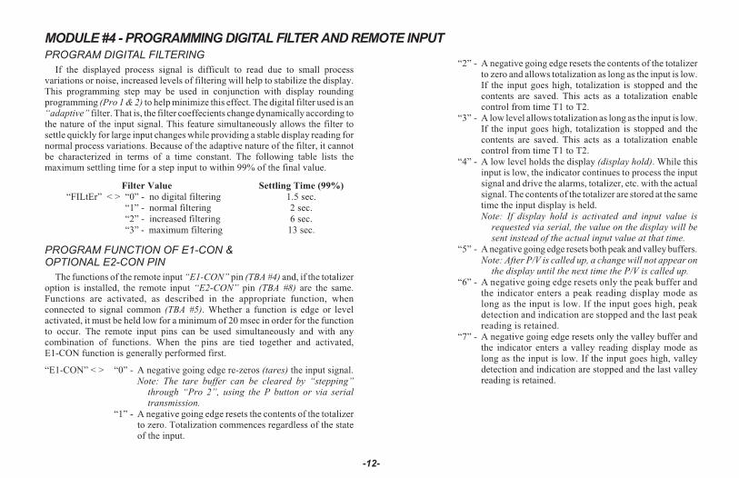
PROGRAM DIGITAL FILTERING
If the displayed process signal is difficult to read due to small processvariations or noise, increased levels of filtering will help to stabilize the display.This programming step may be used in conjunction with display roundingprogramming (Pro 1 & 2) to help minimize this effect. The digital filter used is an“adaptive” filter. That is, the filter coeffecients change dynamically according tothe nature of the input signal. This feature simultaneously allows the filter tosettle quickly for large input changes while providing a stable display reading fornormal process variations. Because of the adaptive nature of the filter, it cannotbe characterized in terms of a time constant. The following table lists themaximum settling time for a step input to within 99% of the final value.
Filter Value Settling Time (99%)
“FILtEr” < > “0” - no digital filtering 1.5 sec.
“1” - normal filtering 2 sec.
“2” - increased filtering 6 sec.
“3” - maximum filtering 13 sec.
PROGRAM FUNCTION OF E1-CON &OPTIONAL E2-CON PIN
The functions of the remote input “E1-CON” pin (TBA #4) and, if the totalizeroption is installed, the remote input “E2-CON” pin (TBA #8) are the same.Functions are activated, as described in the appropriate function, whenconnected to signal common (TBA #5). Whether a function is edge or levelactivated, it must be held low for a minimum of 20 msec in order for the functionto occur. The remote input pins can be used simultaneously and with anycombination of functions. When the pins are tied together and activated,E1-CON function is generally performed first.
“E1-CON” < > “0” - A negative going edge re-zeros (tares) the input signal.
Note: The tare buffer can be cleared by “stepping”through “Pro 2”, using the P button or via serialtransmission.
“1” - A negative going edge resets the contents of the totalizerto zero. Totalization commences regardless of the stateof the input.
“2” - A negative going edge resets the contents of the totalizerto zero and allows totalization as long as the input is low.If the input goes high, totalization is stopped and thecontents are saved. This acts as a totalization enablecontrol from time T1 to T2.
“3” - A low level allows totalization as long as the input is low.If the input goes high, totalization is stopped and thecontents are saved. This acts as a totalization enablecontrol from time T1 to T2.
“4” - A low level holds the display (display hold). While thisinput is low, the indicator continues to process the inputsignal and drive the alarms, totalizer, etc. with the actualsignal. The contents of the totalizer are stored at the sametime the input display is held.
Note: If display hold is activated and input value isrequested via serial, the value on the display will besent instead of the actual input value at that time.
“5” - A negative going edge resets both peak and valley buffers.
Note: After P/V is called up, a change will not appear onthe display until the next time the P/V is called up.
“6” - A negative going edge resets only the peak buffer andthe indicator enters a peak reading display mode aslong as the input is low. If the input goes high, peakdetection and indication are stopped and the last peakreading is retained.
“7” - A negative going edge resets only the valley buffer andthe indicator enters a valley reading display mode aslong as the input is low. If the input goes high, valleydetection and indication are stopped and the last valleyreading is retained.
-12-
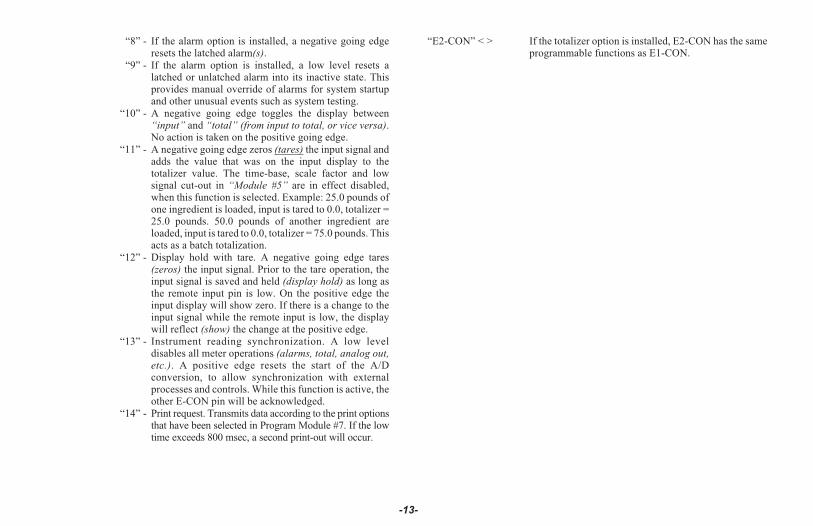
“8” - If the alarm option is installed, a negative going edgeresets the latched alarm(s).
“9” - If the alarm option is installed, a low level resets alatched or unlatched alarm into its inactive state. Thisprovides manual override of alarms for system startupand other unusual events such as system testing.
“10” - A negative going edge toggles the display between“input” and “total” (from input to total, or vice versa).No action is taken on the positive going edge.
“11” - A negative going edge zeros (tares) the input signal andadds the value that was on the input display to thetotalizer value. The time-base, scale factor and lowsignal cut-out in “Module #5” are in effect disabled,when this function is selected. Example: 25.0 pounds ofone ingredient is loaded, input is tared to 0.0, totalizer =25.0 pounds. 50.0 pounds of another ingredient areloaded, input is tared to 0.0, totalizer = 75.0 pounds. Thisacts as a batch totalization.
“12” - Display hold with tare. A negative going edge tares(zeros) the input signal. Prior to the tare operation, theinput signal is saved and held (display hold) as long asthe remote input pin is low. On the positive edge theinput display will show zero. If there is a change to theinput signal while the remote input is low, the displaywill reflect (show) the change at the positive edge.
“13” - Instrument reading synchronization. A low leveldisables all meter operations (alarms, total, analog out,etc.). A positive edge resets the start of the A/Dconversion, to allow synchronization with externalprocesses and controls. While this function is active, theother E-CON pin will be acknowledged.
“14” - Print request. Transmits data according to the print optionsthat have been selected in Program Module #7. If the lowtime exceeds 800 msec, a second print-out will occur.
“E2-CON” < > If the totalizer option is installed, E2-CON has the sameprogrammable functions as E1-CON.
-13-

MODULE #5 - PROGRAM TOTALIZER/INTEGRATORProgramming for the totalizer/integrator consists of four programming steps:
totalizer decimal point position, time base, scale factor and low signal disable.Note that the decimal point position of the totalizer can be independent of thedecimal point position of the scaled input signal. The totalizer value will roll overand flash when the total exceeds, 999999 or -99999, indicating an overflowcondition. Reverse signal input will cause the totalizer value to count in theopposite direction and eventually no longer be in an overflow condition.
PROGRAM DECIMAL POINT POSITION FOR THE TOTALIZER
The decimal point position for the totalizer are as follows:
“dECPNt” < > “0”“0.0”“0.00”“0.000”“0.0000”
PROGRAM TOTALIZER/INTEGRATOR TIME BASE
The time base determines the rate at which readings increase. The totalizerdisplay is updated 2 1/2 times per second regardless of time base selected, butlonger time bases decrease the magnitude of each increase. The three time basesare per second, per minute and per hour. A constant signal input of 1000 units, forexample, would totalize to 1000 units in one second (with a TB of 1 sec.), 1000units in one minute (with a TB of 1 min.), and 1000 units in one hour (with a TB of1 hr.). (Note: Input changes can be made synchronous to the display byprogramming E1 or optional E2-CON pin for function 13, Instrument readingsynchronization.) A multiplying scale factor may be used to span the standardtime ranges (or divide if scale factor < 1). The following equation expresses thetotalization process.
S.F.D.T.
I.D.
T.B.
TIME
D.T.D.P.
I. D. D. P.� � �
S.F. = Programmable Scale FactorD.T. = Desired Totalizer value for a
fixed time durationT.B. = Programmable Time Base
TB = If Program Select Number Chosen Is: Enter in Formula“0” for sec. 1“1” for min. 60“2” for hr. 3600
I.D. = Input Display ValueTIME = Actual Time period in seconds
D.T.D.P. = Desired Totalizer Decimal Point Enter in Formula0 10.0 100.00 1000.000 10000.0000 10000
I.D.D.P. = Input Display Value Decimal Point Enter in Formula0 10.0 100.00 1000.000 10000.0000 10000
“tbASE” < > “0” - per second“1” - per minute“2” - per hour
PROGRAM THE TOTALIZER SCALE FACTOR
As explained in the previous programming step, a multiplying scale factor canbe used to scale the update rate as required. This may be used to span the standardranges. A scale factor of “1.000” has no effect on the standard ranges.
“SCLFAC” < > “0.001” to “100.000”
PROGRAM THE LOW-END CUTOUT (low signal level disable)
In order to prevent false totalization during system startup or other low processsituations where totalization is undesirable, a programmable setpoint can be usedto disable totalization when the scaled input signal falls below this low-endcutout level.
“Lo-cut” < > “-99999” to “999999”
-14-
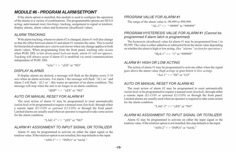
MODULE #6 - PROGRAM ALARM/SETPOINTIf the alarm option is installed, this module is used to configure the operation
of the alarms to a variety of combinations. The programmable options are HI/LOacting, auto/manual reset (latching), tracking, assignment to signal or totalizer,display alarms, alarm values and hysteresis (deadband) values.
ALARM TRACKING
With alarm tracking, whenever alarm #2 is changed, alarm #1 will also changeso that the offset between alarm #2 and alarm #1 remains the same. This is usefulfor hierarchical setpoints (pre-alarm and alarm) when one change applies to bothalarm values. When programming from the front panel, tracking only occurswhen PGM. DIS. is low (front panel lock-out mode, alarm #1 will not appear).Tracking will always occur if alarm #2 is modified via serial communicationsindependent of PGM. DIS.
“trAc” < > “yES” or “NO”
DISPLAY ALARMS
If display alarms are desired, a message will flash on the display every 5-10secs when an alarm activates. For alarm 1 the message will flash “AL1 on” andalarm 2 will flash “AL2 on”, this warns an operator of an alarm condition. Themessage will stop when the unit is no longer in an alarm condition.
“dISP” < > “yES” or “NO”
AUTO OR MANUAL RESET FOR ALARM #1
The reset action of alarm #1 may be programmed to reset automatically(unlatched) or be programmed to require a manual reset (latched), through eithera remote input (E1-CON or optional E2-CON) or through the front panel.Latched alarms are usually used when an operator is required to take some actionfor the alarm condition.
“LAtC-1” < > “yES” or “NO”
ALARM #1 ASSIGNMENT TO INPUT SIGNAL OR TOTALIZER
Alarm #1 may be programmed to activate on either the input signal or thetotalizer value. If the totalizer option is not installed, this step defaults to the input.
“ASN-1” < > “INPUt” or “totAL”
PROGRAM VALUE FOR ALARM #1
The range of the alarm value is -99,999 to 999,999.
“AL-1” < > “-99999” to “999999”
PROGRAM HYSTERESIS VALUE FOR ALARM #1 (Cannot beprogrammed if alarm latch is programmed)
The hysteresis (deadband) value for alarm #1 may be programmed from 1 to99,999. The value is either added to or subtracted from the alarm value dependingon whether the alarm is high or low acting. (See “alarms” section for operation.)
“HyS-1” < > “1” to “999999”
ALARM #1 HIGH OR LOW ACTING
The action of alarm #1 may be programmed to activate either when the signalgoes above the alarm value (high acting) or goes below it (low acting).
“Act-1” < > “HI” or “LO”
AUTO OR MANUAL RESET FOR ALARM #2
The reset action of alarm #2 may be programmed to reset automatically(unlatched) or be programmed to require a manual reset (latched), through eithera remote input (E1-CON or optional E2-CON) or through the front panel.Latched alarms are usually used when an operator is required to take some actionfor the alarm condition.
“LAtC-2” < > “yES” or “NO”
ALARM #2 ASSIGNMENT TO INPUT SIGNAL OR TOTALIZER
Alarm #2 may be programmed to activate on either the input signal or thetotalizer value. If the totalizer option is not installed, this step defaults to the input.
“ASN-2” < > “INPUt” or “totAL”
-15-

PROGRAM VALUE FOR ALARM #2
The range of the alarm value is -99,999 to 999,999.
“AL-2” < > “-99999” to “999999”
PROGRAM HYSTERESIS VALUE FOR ALARM #2 (Cannot beprogrammed if alarm latch is programmed)
The hysteresis (deadband) value for alarm #2 may be programmed from 1 to999,999. The value is either added to or subtracted from the alarm value dependingon whether the alarm is high or low acting. (See “alarms” section for operation.)
“HyS-2” < > “1” to “999999”
ALARM #2 HIGH OR LOW ACTING
The action of alarm #2 may be programmed to activate either when the signalgoes above the alarm value (high acting) or goes below it (low acting).
“Act-2” < > “HI” or “LO”
Note: Depending on options selected under Pro 3 and Pro 6, alarms, hysteresis,peak, and valley values can be monitored and/or changed when PGM. DIS.is tied to COMM. This provides a “QUICK PROGRAMMING” method for“day to day” process changes. (See QUICK PROGRAMMING SECTIONfor more details.)
-16-
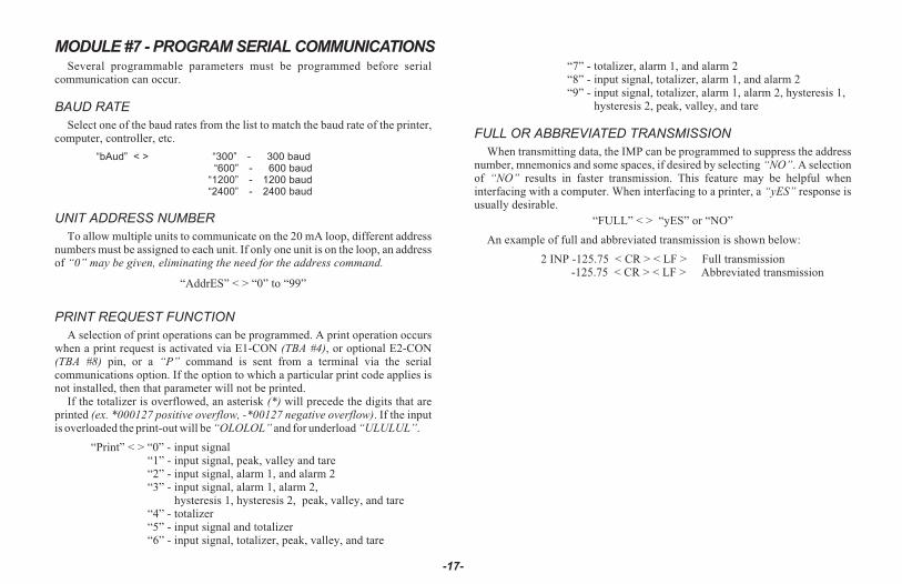
MODULE #7 - PROGRAM SERIAL COMMUNICATIONSSeveral programmable parameters must be programmed before serial
communication can occur.
BAUD RATE
Select one of the baud rates from the list to match the baud rate of the printer,computer, controller, etc.
“bAud” < > “300” - 300 baud“600” - 600 baud
“1200” - 1200 baud“2400” - 2400 baud
UNIT ADDRESS NUMBER
To allow multiple units to communicate on the 20 mA loop, different addressnumbers must be assigned to each unit. If only one unit is on the loop, an addressof “0” may be given, eliminating the need for the address command.
“AddrES” < > “0” to “99”
PRINT REQUEST FUNCTION
A selection of print operations can be programmed. A print operation occurswhen a print request is activated via E1-CON (TBA #4), or optional E2-CON(TBA #8) pin, or a “P” command is sent from a terminal via the serialcommunications option. If the option to which a particular print code applies isnot installed, then that parameter will not be printed.
If the totalizer is overflowed, an asterisk (*) will precede the digits that areprinted (ex. *000127 positive overflow, -*00127 negative overflow). If the inputis overloaded the print-out will be “OLOLOL” and for underload “ULULUL”.
“Print” < > “0” - input signal“1” - input signal, peak, valley and tare“2” - input signal, alarm 1, and alarm 2“3” - input signal, alarm 1, alarm 2,
hysteresis 1, hysteresis 2, peak, valley, and tare“4” - totalizer“5” - input signal and totalizer“6” - input signal, totalizer, peak, valley, and tare
“7” - totalizer, alarm 1, and alarm 2“8” - input signal, totalizer, alarm 1, and alarm 2“9” - input signal, totalizer, alarm 1, alarm 2, hysteresis 1,
hysteresis 2, peak, valley, and tare
FULL OR ABBREVIATED TRANSMISSION
When transmitting data, the IMP can be programmed to suppress the addressnumber, mnemonics and some spaces, if desired by selecting “NO”. A selectionof “NO” results in faster transmission. This feature may be helpful wheninterfacing with a computer. When interfacing to a printer, a “yES” response isusually desirable.
“FULL” < > “yES” or “NO”
An example of full and abbreviated transmission is shown below:
2 INP -125.75 < CR > < LF > Full transmission-125.75 < CR > < LF > Abbreviated transmission
-17-
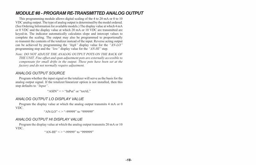
MODULE #8 - PROGRAM RE-TRANSMITTED ANALOG OUTPUTThis programming module allows digital scaling of the 4 to 20 mA or 0 to 10
VDC analog output. The type of analog output is determined by the model ordered.(See Ordering Information for available models.) The display value at which 4 mAor 0 VDC and the display value at which 20 mA or 10 VDC are transmitted arekeyed-in. The indicator automatically calculates slope and intercept values tocomplete the scaling. The output may also be programmed to proportionallyre-transmit the contents of the totalizer instead of the input. Reverse acting outputcan be achieved by programming the “high” display value for the “AN-LO”programming step and the “low” display value for the “AN-HI” step.
Note: DO NOT ADJUST THE ANALOG OUTPUT POTS ON THE BACK OFTHE UNIT. Fine offset and span adjustment pots are externally accessible tocompensate for small drifts in the output. These pots have been set at thefactory and do not normally require adjustment.
ANALOG OUTPUT SOURCE
Program whether the input signal or the totalizer will serve as the basis for theanalog output signal. If the totalizer/linearizer option is not installed, then thisstep defaults to “Input”.
“ASIN” < > “InPut” or “totAL”
ANALOG OUTPUT LO DISPLAY VALUE
Program the display value at which the analog output transmits 4 mA or 0VDC.
“AN-LO” < > “-99999” to “999999”
ANALOG OUTPUT HI DISPLAY VALUE
Program the display value at which the analog output transmits 20 mA or 10VDC.
“AN-HI” < > “-99999” to “999999”
-18-
MODULE #9 - SERVICE OPERATIONSThe indicator has been fully calibrated at the factory and will only require a
scaling operation (Pro 1 or 2) to display the units of the process. If the unitappears to be indicating incorrectly or inaccurately, refer to the troubleshootingsection before attempting this procedure.
When re-calibration is required (generally every 2 years), this procedureshould only be performed by qualified technicians using appropriate equipment.Signal source accuracies of 0.01% or better are required.
The procedure consists of applying accurate signal levels to the indicator in aseries of three steps. Allow a 30 minute warm-up period before starting thisprocedure.
Note: Once the access Code 48 has been entered, there is no exiting this programmodule without completing the calibrating procedure.
ENTER ACCESS CODE
A code number (48) must be keyed-in prior to the calibration sequence toguard against inadvertent entries. Access code numbers other than those listed inthis section, should not be entered at this step. If any are entered, undefined orunpredictable operation could result.
“CodE” < > “0” to “99”
If the code number for the previous step was not recognized, the indicatorreturns to “Pro 0”, with no action taken. Otherwise, the calibration procedureis started.
ENTER ZERO REFERENCE
Apply 0 mA by opening the signal input wires.
“StEP 1” (Press “P”)
ENTER 50% OF PROCESS
Apply 25 mA. Allow the signal to stabilize for 20 seconds before pressing “P”.
“StEP 2” (Press “P”)
The indicator will display “StEP -” for ten seconds. During this interval, keepthe signal level applied until “StEP 3” appears.
ENTER 100% OF PROCESS
Apply 50 mA. Allow the signal to stabilize for 20 seconds before pressing “P”.
“StEP 3” (Press “P”)
Indicator calibration is complete. It is recommended that calibration bechecked by entering “Pro 1” and checking the displayed input values with thesignal source at different applied input levels.
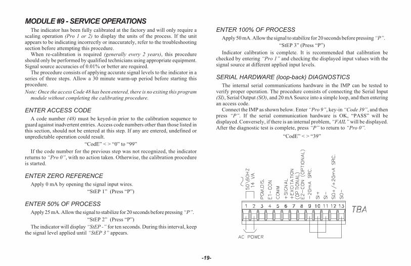
SERIAL HARDWARE (loop-back) DIAGNOSTICS
The internal serial communications hardware in the IMP can be tested toverify proper operation. The procedure consists of connecting the Serial Input(SI), Serial Output (SO), and 20 mA Source into a simple loop, and then enteringan access code.
Connect the IMP as shown below. Enter “Pro 9”, key-in “Code 39”, and thenpress “P”. If the serial communication hardware is OK, “PASS” will bedisplayed. Conversely, if there is an internal problem, “FAIL” will be displayed.After the diagnostic test is complete, press “P” to return to “Pro 0”.
“CodE” < > “39”
-19-
RESTORING ALL PROGRAMMING PARAMETERS BACK TOFACTORY CONFIGURATION
All of the programming in Modules #1 through #8 can be restored back to thefactory configuration by entering a specific access code (refer to the “FactoryConfiguration” section for the data that will be entered). The procedure consists ofentering “Pro 9”, keying-in “Code 66”, and then pressing “P”. The IMP respondsby displaying “INItAL” for several seconds, and then returns to “Pro 0”.Note: When this procedure is performed, all of the scaling, presets, etc. that were
programmed into the IMP will be overwritten.
“COdE” < > “66”
OPERATING THE IMP
After completing scaling and all set-up operations, the unit is ready to installand operate. After power is applied, a display test consisting of illuminating allsegments for 2 seconds is performed. Afterward, the input or total will appear,depending upon the display mode prior to the last power-down. To switch thedisplay to input, press “DOWN” (indicated by “arrows” on the front panel) andto switch it to total, press “UP”. If the totalizer/linearizer option is not installed,then display switching to total is inoperative. A minus sign “-” will precedenumbers that are negative. If a decimal point is chosen, one leading and one ormore trailing zeros will accompany the decimal point.
QUICK PROGRAMMING
To limit access to the set-up parameters, connect a key-switch or wire fromPGM. DIS. (TBA #3) to COMM. (TBA #5).With this pin connected to common,only a predetermined amount of data can be viewed or altered, as programmed byprogramming module #3. If “NO” was programmed for all of the available stepsin module #3, then pressing “P” will cause the unit to display “Loc”. However, if“YES” was programmed in one or more of the steps, then “P” will invoke entryinto a series of commonly modified parameters while protecting the crucialset-up information. This is referred to as the “quick programming” mode. When“quick programming” mode is entered, the alarms and hysteresis values can bemodified in the same manner as in the regular programming mode. The newalarm and hysteresis values will take effect when “P” is pressed. The otheroperations in the quick programming" mode require special key sequences asshown at right.
To reset latched alarm, scroll through steps in “quickprogramming” mode using the “P” button until “LAtCH1” or“LAtCH2” appears in the display. If they do not appear, they arenot latched.
To reset: While “LAtCH1” or “LAtCH2” is beingdisplayed, press and hold “DOWN” and press “P”.Pressing “P” alone causes a step to the next item withno action taken on the alarm.
To reset peak and valley buffers, scroll through steps in “quickprogramming” mode using the “P” button until “PEA” or “VAL”appears in the display.
To reset: While “PEA” or “VAL” is being displayed,press and hold “DOWN” and press “P”. Pressing“P” alone causes a step to the next item with noaction taken on the buffer.
The front panel buttons are not only used to input data during the programmingand “quick programming” mode, but control a number of other functions (ifenabled in Pro “3”) as well. In the normal meter mode, these functions areavailable:
To Switch to display of input: Press “DOWN” button.To Switch to display of totalizer: Press “UP” button.To re-zero input (tare): Press and hold “DOWN” and press “P”.To reset totalizer to zero: Press and hold “UP” and press “P”.To Enter programming or “quick programming”: Press “P”.
After each operation, a message will appear briefly to acknowledge the action.
-20-
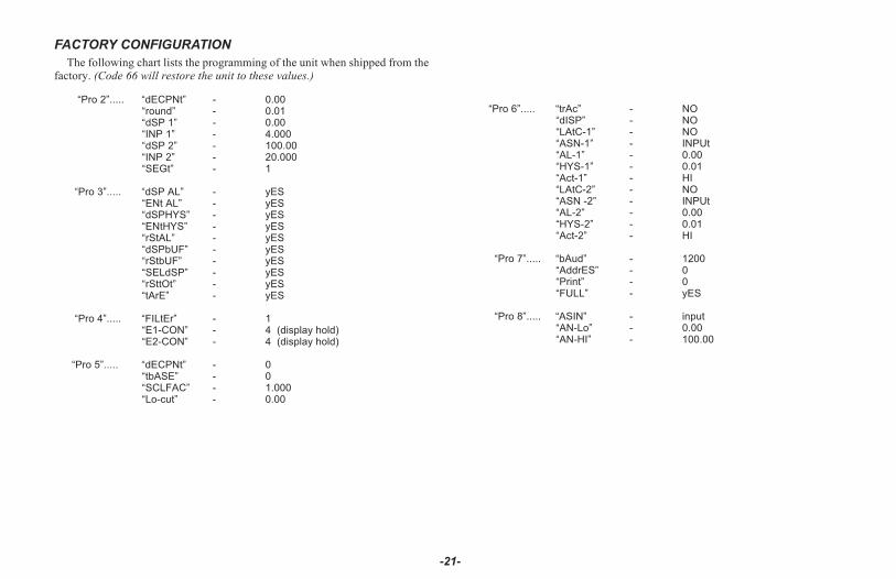
FACTORY CONFIGURATION
The following chart lists the programming of the unit when shipped from thefactory. (Code 66 will restore the unit to these values.)
“Pro 2”..... “dECPNt” - 0.00“round” - 0.01“dSP 1” - 0.00“INP 1” - 4.000“dSP 2” - 100.00“INP 2” - 20.000“SEGt” - 1
“Pro 3”..... “dSP AL” - yES“ENt AL” - yES“dSPHYS” - yES“ENtHYS” - yES“rStAL” - yES“dSPbUF” - yES“rStbUF” - yES“SELdSP” - yES“rSttOt” - yES“tArE” - yES
“Pro 4”..... “FILtEr” - 1“E1-CON” - 4 (display hold)“E2-CON” - 4 (display hold)
“Pro 5”..... “dECPNt” - 0“tbASE” - 0“SCLFAC” - 1.000“Lo-cut” - 0.00
“Pro 6”..... “trAc” - NO“dISP” - NO“LAtC-1” - NO“ASN-1” - INPUt“AL-1” - 0.00“HYS-1” - 0.01“Act-1” - HI“LAtC-2” - NO“ASN -2” - INPUt“AL-2” - 0.00“HYS-2” - 0.01“Act-2” - HI
“Pro 7”..... “bAud” - 1200“AddrES” - 0“Print” - 0“FULL” - yES
“Pro 8”..... “ASIN” - input“AN-Lo” - 0.00“AN-HI” - 100.00
-21-
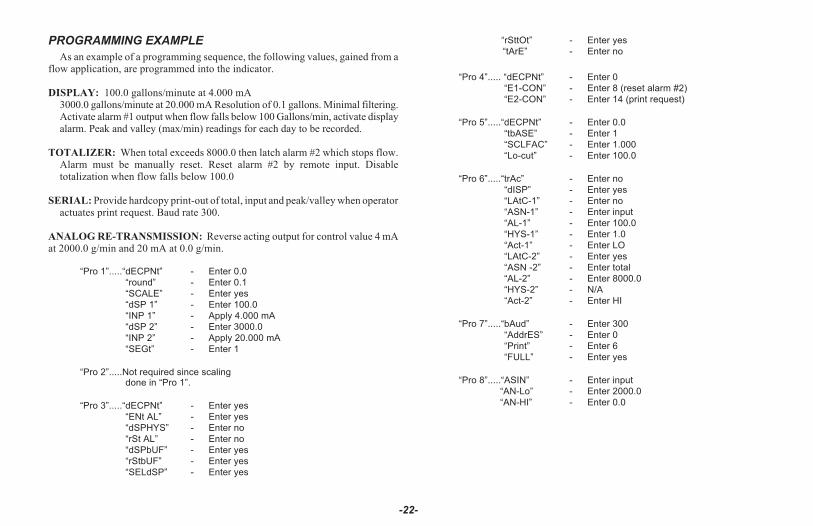
PROGRAMMING EXAMPLE
As an example of a programming sequence, the following values, gained from aflow application, are programmed into the indicator.
DISPLAY: 100.0 gallons/minute at 4.000 mA3000.0 gallons/minute at 20.000 mA Resolution of 0.1 gallons. Minimal filtering.Activate alarm #1 output when flow falls below 100 Gallons/min, activate displayalarm. Peak and valley (max/min) readings for each day to be recorded.
TOTALIZER: When total exceeds 8000.0 then latch alarm #2 which stops flow.Alarm must be manually reset. Reset alarm #2 by remote input. Disabletotalization when flow falls below 100.0
SERIAL: Provide hardcopy print-out of total, input and peak/valley when operatoractuates print request. Baud rate 300.
ANALOG RE-TRANSMISSION: Reverse acting output for control value 4 mAat 2000.0 g/min and 20 mA at 0.0 g/min.
“Pro 1”.....“dECPNt” - Enter 0.0
“round” - Enter 0.1
“SCALE” - Enter yes
“dSP 1” - Enter 100.0
“INP 1” - Apply 4.000 mA
“dSP 2” - Enter 3000.0
“INP 2” - Apply 20.000 mA
“SEGt” - Enter 1
“Pro 2”.....Not required since scalingdone in “Pro 1”.
“Pro 3”.....“dECPNt” - Enter yes
“ENt AL” - Enter yes
“dSPHYS” - Enter no
“rSt AL” - Enter no
“dSPbUF” - Enter yes
“rStbUF” - Enter yes
“SELdSP” - Enter yes
“rSttOt” - Enter yes
“tArE” - Enter no
“Pro 4”..... “dECPNt” - Enter 0
“E1-CON” - Enter 8 (reset alarm #2)
“E2-CON” - Enter 14 (print request)
“Pro 5”.....“dECPNt” - Enter 0.0
“tbASE” - Enter 1
“SCLFAC” - Enter 1.000
“Lo-cut” - Enter 100.0
“Pro 6”.....“trAc” - Enter no
“dISP” - Enter yes
“LAtC-1” - Enter no
“ASN-1” - Enter input
“AL-1” - Enter 100.0
“HYS-1” - Enter 1.0
“Act-1” - Enter LO
“LAtC-2” - Enter yes
“ASN -2” - Enter total
“AL-2” - Enter 8000.0
“HYS-2” - N/A
“Act-2” - Enter HI
“Pro 7”.....“bAud” - Enter 300
“AddrES” - Enter 0
“Print” - Enter 6
“FULL” - Enter yes
“Pro 8”.....“ASIN” - Enter input
“AN-Lo” - Enter 2000.0
“AN-HI” - Enter 0.0
-22-
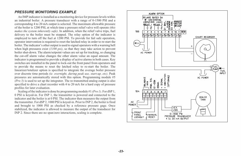
PRESSURE MONITORING EXAMPLE
An IMP indicator is installed as a monitoring device for pressure levels withinan industrial boiler. A pressure transducer with a range of 0-1500 PSI and acorresponding 4 to 20 mA output is selected. The maximum allowable pressureof the boiler is 1200 PSI, at which time a pressure relief valve will operate (thismakes the system inherently safe). In addition, when the relief valve trips, fueldelivery to the boiler must be stopped. The relay option of the indicator isemployed to turn off the fuel at 1200 PSI. To provide for fail safe operation,operator intervention is required to reset the latched relay in order to re-start theboiler. The indicator’s other output is used to signal operators with a warning bellwhen high pressures exist (1100 psi), so that they may take action to preventboiler shut-down. The alarm/setpoint values are set up for tracking, so changingthe cut-off alarm value changes the other alarm value an equal amount. Theindicator is programmed to provide a display of active alarms in both cases. Keyswitches are installed in the panel to lock-out the front panel from operators andto provide the means to reset the latched relay to re-start the boiler. Thelinearizer/totalizer option is specified to integrate the average boiler pressureover discrete time periods (ie. overnight, during peak use, start-up, etc). Peakpressures are automatically stored with this option. Programming module #5(Pro 5) is used to set up the integrator. The re-transmitted analog output is alsospecified to drive a chart recorder with 4 to 20 mA for a hard copy of pressureprofiles for later evaluation.
Scaling of the indicator is done by programming module #1 (Pro 1). For dSP 1,0 PSI is keyed-in. For INP 1, the transmitter is powered and connected to theindicator and the boiler is at 0 PSI. The indicator then measures the output fromthe transmitter. For dSP 2, 1000 PSI is keyed-in. Prior to INP 2, the boiler is firedand brought to 1000 PSI as checked by a reference pressure gage. Oncestabilized, the indicator is allowed to measure the output of the transducer forINP 2. Since there are no span/zero interactions, scaling is complete.
-23-
EXCITATION (Optional)The optional regulated excitation voltage (18 VDC, 60 mA max.) can be used
to power the transducer. The common of the excitation voltage is internallyconnected to “COMM” (TBA #5). The excitation voltage is NOT to be used forpowering relay coils, serial communication loops, etc., due to the sensitive natureof signal common.
TOTALIZER/LINEARIZER/PEAK/VALLEY/TARE(Optional)
TOTALIZER
The totalizer option simply totals (adds) input readings together using aprogrammable time base and scaling coefficient. The decimal point position of thetotalizer can be programmed independent of the input signal. The totalizer may bereset through a remote input, by the front panel or through the serialcommunications option. Alarms may be programmed to trigger from totalizervalues; for example to total flow for batching operations. The programmable timebases are “per second”, “per minute” and “per hour”, meaning the totalizer willaccumulate at a fixed rate of 21
2 times per second and be equal to a fixed inputsignal level over the selected time period. For example, if the input signal is aconstant 1000 units and the “per minute” time base is selected, the totalizer willaccumulate at the rate of 1000 units per minute. The totalizer is updated at this rateevery 400 msec. As a result, the input signal is accumulated in “batches” of 6.6counts every 400 msec. Therefore, the totalizer start and stop sequencing, as wellas, the alarm values set to trigger at specific totalizer values, are accurate only to the400 msec totalizer update rate. The preceding example requires a scale factor of1.000 to yield exact time bases, but any scale factor can be used to span between theranges. (See section on totalizer programming for detailed information.) Aprogrammable low signal level disable feature completes the totalizer features(this will stop totalization when the signal level drops below this programmedvalue, “low cut”). At loss of power to the indicator, the contents of the totalizer aresaved. This will allow totalizing over consecutive shifts, days, etc. The total canaccumulate to 999,999. If the low-end cutout value is programmed negative (ex.-100, reference Program Module #5), and the input signal is between zero and thelow-end cutout value, the totalizer value will decrement. If the input signal goesabove zero the total will increment. If the signal goes below (more negative than),the low-end cutout value, totalization will stop.
Note: The totalizer value will roll over and flash when the total exceeds, 999999or -99999, indicating an overflow condition. Reverse signal input will causethe totalizer value to count in the opposite direction and eventually no longerbe in an overflow condition.
TOTALIZER EXAMPLE
The indicator is employed to indicate and totalize the electrical powerconsumption of a factory. A power meter with a 4-20 mA output that correspondsto 0 to 10 kW is selected. The input is scaled to read instantaneous power draw inkilowatts with 0.001 kW resolution and the totalizer is scaled to readkilowatt-hours. The following programming steps are followed:
BASIC SCALING
“Pro 2”.....“dECPNt” - 0.000“round ” - 0.001“dSP 1” - 0.000“INP 1” - 4.000“dSP 2” - 10.000“INP 2” - 20.000
TOTALIZER SET-UP
With an average signal input which gives a Process Display of 1.000 kW for aone-hour time period, the following formula applies:
S.F. =D.T.
xT.B.
XD.T.D.P.
I.D. TIME I.D.D.P.
S.F. = Programmable Scale FactorD.T. = Desired Totalizer value for a
fixed time durationT.B. = Programmable Time Base
TB = If Program Select Number Chosen Is: Enter in Formula“0” for sec. 1“1” for min. 60“2” for hr. 3600
I.D. = Input Display ValueTIME = Actual Time period in seconds
-24-

TOTALIZER SET-UP (Cont’d)
D.T.D.P. = Desired Totalizer Decimal Point Enter in Formula
0 1
0.0 10
0.00 100
0.000 1000
0.0000 10000
I.D.D.P. = Input Display Decimal Point Enter in Formula
0 1
0.0 10
0.00 100
0.000 1000
0.0000 10000
S. F1KW
1.000KW
3600* *
3600
1
1000
*� ��
�
��
�
�
�� �
S. F.1
1000�
S.F. = .001
“Pro 5”..... “dECPNt” - 0“tbASE” - 2“SCLFAC” - 0.001“Lo-cut” - 0.000
The totalizer will totalize up to 999,999 Kilowatt hours.Alternatively, the totalizer can be scaled to indicate in terms of dollars and
cents of consumed power. If the rate of electricity is 7 cents/kWH then thefollowing set-ups are made:
S. F.07 / KW
1.000KW
3600* *
3600
100
1
*� ��
�
��
�
�
�� �
000SF .007�
“Pro 5”..... “dECPNt” - 0.00“tbASE” - 2“SCLFAC” - 0.007“Lo-cut” - 0.000
The totalizer will totalize up to 9999.99 dollars in .01 dollar resolution.
*This value is normally 1, but can be used as a coarse scale factor of 60 or 3600.**Since the time period is in Hrs., the selected T.B. is 3600 (Program Select
Value = 2) which equals per hour (3600 sec.)
LINEARIZER
The linearizer feature is a series of programmable scaling points that are usedto construct linear segments to linearize the input signal. The most commonapplication would be to interface with square law devices (commonly, flowtransducers). Correction for non-linearity is accomplished by continuing withscaling points beyond “DSP 2” and “INP 2” in “Pro 1” or “Pro 2”, with “DSP3”, and “INP 3”, “DSP 4”, and “INP 4”, etc. The unit automatically calculatesthe linear segments between the programmed coordinates. This process ofentering linear segments is also known as “curve fitting”. A maximum of ninesegments are available and using nine segments for a square law device wouldreduce linearity errors to approximately 0.35%. No restriction is placed on theordering of the scaling points as long as the input signal scaling points are allincreasing or all decreasing. To have one or more points “back-track”, theinput/output (signal/display) relationship would not be a function and would beundefined in that area. Additionally, consideration should be given to thelocation and length of each segment to fully minimize the segment conformityerror over the desired range. A typical curve is shown below using five segments(six scaling points). Usually it is desirable to use as many segments as possible toreduce the amount of linearity error.
-25-
LINEARIZING FUNCTION

LINEARIZER (Cont’d)
The computer program in Appendix “C” outputs the display and process (input)scaling points (the location of each linear segment) as a percentage of the full scaleinput (eg. 4-20 mA) and full scale display (eg. 0-1000 gpm). To obtain the actualinput and display scaling points, multiply the respective percent of full scale valuesby the respective full scale range for the input and the display. “Pro 2” is then usedto enter these values into the IM unit. Certain linear sections of a given curve mayhave a slope which exceeds the measuring resolution of the instrument. The effectwill be an erratic display in that part of the curve, if not corrected (generally, ifslope 2 counts/uA). Correcting for this condition consists of three steps: increasedigital filtering to level 1 or level 2, decrease display resolution to 2 or 5 or adddummy right hand zeros by programming 10 or 100 for “round”.
The following display and process percentage tables were derived from thecomputer program in Appendix “C” (Reference Appendix C section for moredetails). The display and process percentage tables listed below can be used forANY square law (square root extraction) device.
The results of the computer program are as follows:Number of linear segments = 9Curve fitting error (%) = 0.35
Display Values Process Values(% of Range) (% of Range)
0.00 0.006.32 0.20
10.43 1.0018.04 3.1027.58 7.4039.09 15.0052.61 27.3068.18 46.0085.74 72.90
100.00 100.00As an example, to linearize a 4-20 mA flow transmitter, with the following
flow equation:
Flow(gpm) = 44.7 P
where: P = 0-500 PSIFlow = 0-1000 gpm
Now, using the above percentages, the actual process (input) signal anddisplay scaling points must be calculated. To do this for the display values, it issimply the display percentage times the full scale display range. i.e. 18.04% x1000 gpm = 180.04; 68.18% x 1000 = 681.8 etc.
To calculate the process (input) values, multiply the process percentage timesthe full scale process differential, then add in the process offset value. i.e. For theprocess range of 4-20 mA, [3.10% x (20 mA - 4 mA)] + 4 mA = 4.496 mA;[27.30% x (20 mA - 4 mA)] + 4 mA = 8.368 mA. If the process range were 10-50mA, then the results would be as follows: [3.10% x (50 mA - 10 mA)] + 10 mA =11.24 mA; [27.30% x (50 mA - 10 mA)] + 10 mA = 20.92 mA.
The tables below show the scaling points calculated for the 4-20 mA process(input) along with the corresponding display values.
DISPLAY PROCESS (INPUT)(%FS 0-1000 gpm*) (%FS 4-20 mA*)
0.00 0 0.00 46.32 63.2 0.20 4.032
10.43 104.30 1.00 4.1618.04 180.40 3.10 4.49627.58 275.80 7.40 5.18439.09 390.90 15.00 6.40052.61 526.10 27.30 8.36868.18 681.80 46.00 11.36085.74 857.40 72.90 15.664
100.00 1000.00 100.00 20.000* The values shown in this column are user calculated.
Note: These full scale percentage values for process and display can be appliedto ANY square law device.
The example below shows a 10-50 mA square law transducer using the samepercent of full scale numbers with nine segments as the 4-20 mA device.
Flow(gpm) = 42.4 P
where: P = 0-1250 PSIFlow = 0-1500 gpm
-26-
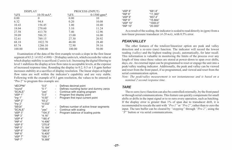
DISPLAY PROCESS (INPUT)%FS 10-50 mA* %FS 0-1500 gpm*0.00 0 0.00 106.32 94.8 0.20 10.0810.43 156.45 1.00 10.4018.04 270.60 3.10 11.2427.58 413.70 7.40 12.9639.09 586.35 15.00 16.0052.61 789.15 27.30 20.9268.18 1022.70 46.00 28.4085.74 1286.10 72.90 39.16100.00 1500.00 100.00 50.00
Examination of the data of the first example reveals a slope in the first linearsegment of 63.2 / (4.032-4.000) = 20 display units/uA, which exceeds the value atwhich display stability is sacrificed (2 units/uA). Increasing the digital filtering tolevel 1 stabilizes the display at low flow rates to acceptable levels, at the expenseof increased response time. Rounding the display to 0.2, 0.5 or 1.0 gpm furtherincreases stability at a sacrifice of display resolution. The linear slopes at higherflow rates are well within the indicator’s capability and are very stable.Following with the example of 0.1 gpm resolution, the values to be entered in“Pro 2” to program this example are:
“dECPNt” “0.0” - Defines decimal point“round” “0.1” - Defines rounding factor and dummy zeros“SCALE” “yes” - Continue with scaling program“dSP 1” “0.0” - Program first display point“Inp 1” “4.00” - Program first input current point“dSP 2” “63.2”“Inp 2” “4.032”“SEGt” “9” - Defines number of active linear segments“SCALE” “yes” - Continue with scaling“dSP 3” “104.3” - Program balance of scaling points“INP 3” “4.16”“dSP 4” “180.4”“INP 4” “4.496”“dSP 5” “275.8”“INP 5” “5.184”“dSP 6” “390.9”“INP 6” “6.400”“dSP 7” “526.1”“INP 7” “8.368”
“dSP 8” “681.8”“INP 8” “11.360”“dSP 9” “857.4”“INP 9” “15.664”“dSP 10” “1000.0”“INP 10” “20.000”
As a result of the scaling, the indicator is scaled to read directly in (gpm) from anon-linear pressure transducer (4-20 mA), with 0.5% error.
PEAK/VALLEY
The other features of the totalizer/linearizer option are peak and valleydetection and a re-zero (tare) function. The indicator will record the lowestreading (valley) and the highest reading (peak), automatically, for later recall.This information is valuable in monitoring the limits of the process over anylength of time since these values are stored at power-down to span over shifts,days, etc. An external input can be programmed to reset or engage the unit into apeak/valley reading indicator. Additionally, the peak and valley can be viewedand reset from the front panel, if so programmed, and viewed and reset from theserial communication option.Note: The peak/valley measurement is not instantaneous and is based on a
nominal 2 second response time.
TARE
The re-zero (tare) function can also be controlled externally, by the front panelor through serial communications. This feature can quickly compensate for smallshifts or drifts in the input signal or to re-zero every operation, such as batching.If the display error is greater than 1% of span due to transducer drift, it isrecommended to rescale the unit with “Pro 1” or “Pro 2”, rather than re-zero theinput. The tare buffer can be cleared by “stepping” through “Pro 2”, using the“P” button or via serial communications.
-27-
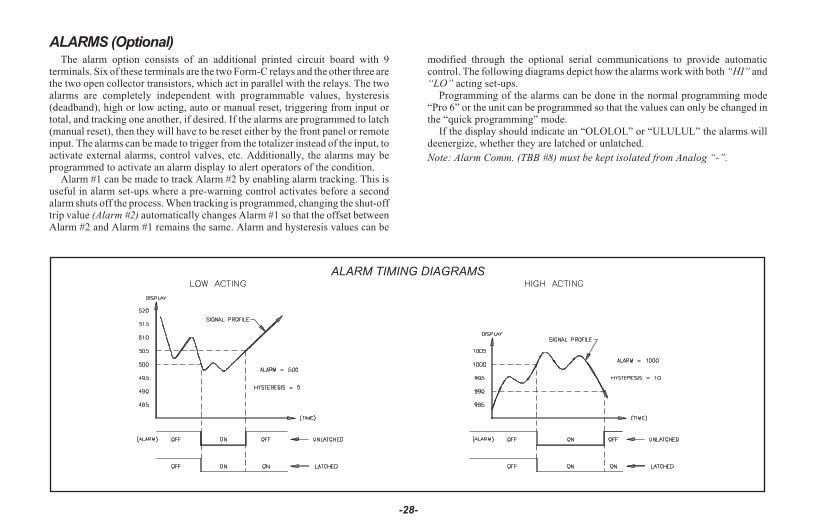
ALARMS (Optional)The alarm option consists of an additional printed circuit board with 9
terminals. Six of these terminals are the two Form-C relays and the other three arethe two open collector transistors, which act in parallel with the relays. The twoalarms are completely independent with programmable values, hysteresis(deadband), high or low acting, auto or manual reset, triggering from input ortotal, and tracking one another, if desired. If the alarms are programmed to latch(manual reset), then they will have to be reset either by the front panel or remoteinput. The alarms can be made to trigger from the totalizer instead of the input, toactivate external alarms, control valves, etc. Additionally, the alarms may beprogrammed to activate an alarm display to alert operators of the condition.
Alarm #1 can be made to track Alarm #2 by enabling alarm tracking. This isuseful in alarm set-ups where a pre-warning control activates before a secondalarm shuts off the process. When tracking is programmed, changing the shut-offtrip value (Alarm #2) automatically changes Alarm #1 so that the offset betweenAlarm #2 and Alarm #1 remains the same. Alarm and hysteresis values can be
modified through the optional serial communications to provide automaticcontrol. The following diagrams depict how the alarms work with both “HI” and“LO” acting set-ups.
Programming of the alarms can be done in the normal programming mode“Pro 6” or the unit can be programmed so that the values can only be changed inthe “quick programming” mode.
If the display should indicate an “OLOLOL” or “ULULUL” the alarms willdeenergize, whether they are latched or unlatched.
Note: Alarm Comm. (TBB #8) must be kept isolated from Analog “-”.
-28-
ALARM TIMING DIAGRAMS
20 mA CURRENT LOOP SERIAL COMMUNICATIONS (Optional)
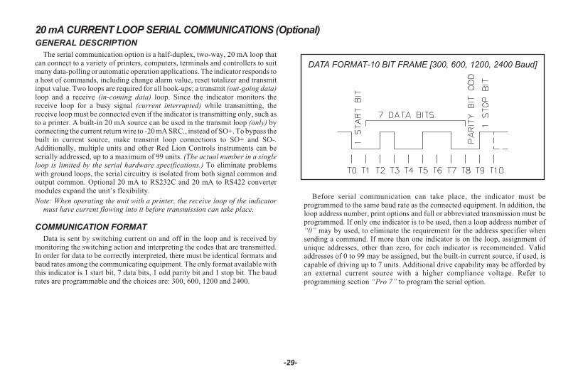
GENERAL DESCRIPTION
The serial communication option is a half-duplex, two-way, 20 mA loop thatcan connect to a variety of printers, computers, terminals and controllers to suitmany data-polling or automatic operation applications. The indicator responds toa host of commands, including change alarm value, reset totalizer and transmitinput value. Two loops are required for all hook-ups; a transmit (out-going data)loop and a receive (in-coming data) loop. Since the indicator monitors thereceive loop for a busy signal (current interrupted) while transmitting, thereceive loop must be connected even if the indicator is transmitting only, such asto a printer. A built-in 20 mA source can be used in the transmit loop (only) byconnecting the current return wire to -20 mA SRC., instead of SO+. To bypass thebuilt in current source, make transmit loop connections to SO+ and SO-.Additionally, multiple units and other Red Lion Controls instruments can beserially addressed, up to a maximum of 99 units. (The actual number in a singleloop is limited by the serial hardware specifications.) To eliminate problemswith ground loops, the serial circuitry is isolated from both signal common andoutput common. Optional 20 mA to RS232C and 20 mA to RS422 convertermodules expand the unit’s flexibility.
Note: When operating the unit with a printer, the receive loop of the indicatormust have current flowing into it before transmission can take place.
COMMUNICATION FORMAT
Data is sent by switching current on and off in the loop and is received bymonitoring the switching action and interpreting the codes that are transmitted.In order for data to be correctly interpreted, there must be identical formats andbaud rates among the communicating equipment. The only format available withthis indicator is 1 start bit, 7 data bits, 1 odd parity bit and 1 stop bit. The baudrates are programmable and the choices are: 300, 600, 1200 and 2400.
Before serial communication can take place, the indicator must beprogrammed to the same baud rate as the connected equipment. In addition, theloop address number, print options and full or abbreviated transmission must beprogrammed. If only one indicator is to be used, then a loop address number of“0” may by used, to eliminate the requirement for the address specifier whensending a command. If more than one indicator is on the loop, assignment ofunique addresses, other than zero, for each indicator is recommended. Validaddresses of 0 to 99 may be assigned, but the built-in current source, if used, iscapable of driving up to 7 units. Additional drive capability may be afforded byan external current source with a higher compliance voltage. Refer toprogramming section “Pro 7” to program the serial option.
-29-
DATA FORMAT-10 BIT FRAME [300, 600, 1200, 2400 Baud]
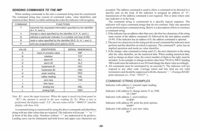
SENDING COMMANDS TO THE IMP
When sending commands to the unit a command string must be constructed.The command string may consist of command codes, value identifiers, andnumerical data. Below is a table outlining the codes the indicator will recognize.
COMMAND FUNCTIONS
T transmits the requested information specified by the identifier(A-I, K, and L)
V change a value specified by the identifier (C-F, K, and L)
N address a particular indicator in a multiple unit loop (0-99)
R reset a value specified by the identifier (B-D, G, H, I, and J)
P print per programmable print options (A-H)
VALUE IDENTIFIERS SERIAL MNEMONICS
A input or process value INP
B totalizer TOT
C alarm #1 AL1
D alarm #2 AL2
E hysteresis #1 HS1
F hysteresis #2 HS2
G peak reading PEK
H valley reading VAL
I zero tare TAR
J tare input —
K analog low ANL
L analog high ANH
Note: RJ - tares the input (rezeros). When the input is tared (via front panel or“RJ”) the amount is stored in the tare reading (I). Ex. When a tare isperformed, the display reads “5.0”, the tare value will be “-00005.0” (and thedisplay will show 0.0).
A command string is constructed by using the above commands and identifiersalong with any data values that are required. The indicator will accept “+” or “-”in front of the data value. Numbers without “+” are understood to be positive.Leading zeros can be eliminated and both lower and upper case characters are
accepted. The address command is used to allow a command to be directed to aspecific unit on the loop. If the indicator is assigned an address of “0”,transmission of the address command is not required. This is done where onlyone indicator is in the loop.
The command string is constructed in a specific logical sequence. Theindicator will reject command strings that do not conform. Only one operationcan be performed per command string. Below is a description of how to constructa command string.1. If the indicator has an address other than zero, the first two characters of the string
must consist of the address command (N) followed by the unit address number(0-99). If the indicator has an address of 0, the address command is optional.
2. The next two characters in the string are the actual command the indicator mustperform and the identifier on which it operates. The command P - print, has animplied operation and needs no value identifier.
3. If the change value command is being used (V), the next characters in the stringafter the value identifier, are the numerical data. When sending numerical data,such as change an alarm value, the correct number of digits to the right, must beincluded. As an example, to change an alarm value from 750.02 to 500.0. Sending500 would cause the indicator to see 50.0 and change the alarm value accordingly.
4. All commands must be terminated by an asterisk(*). The indicator will notrespond to any other code. Carriage return and line feed are not validterminators and should be suppressed with the character “;”, if using a BASICprint statement (ex. Print “N9TA*”;).
COMMAND STRING EXAMPLES
Indicator with address 3, transmit input reading.N3TA*
Indicator with address 0, change alarm #1 to 1500.VC1500*
Indicator with address 1, reset totalizer.N1RB*
Indicator with address 99, print the print options.N99P*
Indicator with address 0, zero tare value.RI*
-30-

If an illegal command or character is sent to the IM, an asterisk (*) must betransmitted to clear the input buffer. The IM will not respond to an illegal orincomplete transmission. The diagrams show the differences in the timingconsiderations for either Abbreviated or Full Character Transmission, or if aReset Command is issued.
Note: If Full Transmission is selected and the front panel is being accessed at thetime of transmission, the IM may take as long as 2 seconds to respond.
-31-
Reset CommandIndependent of Type
of Transmission Selected
Timing Diagrams(Full Transmission Selected)
Timing Diagrams(Abbreviated Transmission Selected)
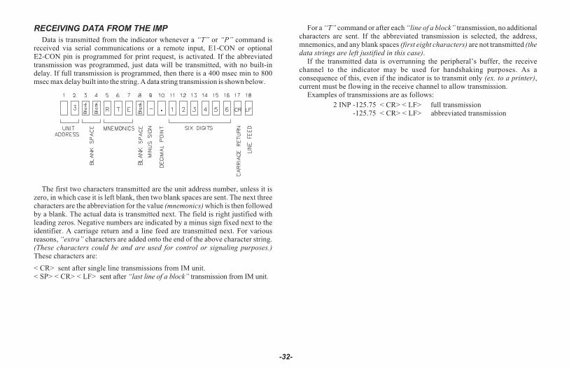
RECEIVING DATA FROM THE IMP
Data is transmitted from the indicator whenever a “T” or “P” command isreceived via serial communications or a remote input, E1-CON or optionalE2-CON pin is programmed for print request, is activated. If the abbreviatedtransmission was programmed, just data will be transmitted, with no built-indelay. If full transmission is programmed, then there is a 400 msec min to 800msec max delay built into the string. A data string transmission is shown below.
The first two characters transmitted are the unit address number, unless it iszero, in which case it is left blank, then two blank spaces are sent. The next threecharacters are the abbreviation for the value (mnemonics) which is then followedby a blank. The actual data is transmitted next. The field is right justified withleading zeros. Negative numbers are indicated by a minus sign fixed next to theidentifier. A carriage return and a line feed are transmitted next. For variousreasons, “extra” characters are added onto the end of the above character string.(These characters could be and are used for control or signaling purposes.)These characters are:
< CR> sent after single line transmissions from IM unit.< SP> < CR> < LF> sent after “last line of a block” transmission from IM unit.
For a “T” command or after each “line of a block” transmission, no additionalcharacters are sent. If the abbreviated transmission is selected, the address,mnemonics, and any blank spaces (first eight characters) are not transmitted (thedata strings are left justified in this case).
If the transmitted data is overrunning the peripheral’s buffer, the receivechannel to the indicator may be used for handshaking purposes. As aconsequence of this, even if the indicator is to transmit only (ex. to a printer),current must be flowing in the receive channel to allow transmission.
Examples of transmissions are as follows:
2 INP -125.75 < CR> < LF> full transmission-125.75 < CR> < LF> abbreviated transmission
-32-

-33-
This page is intentionally left blank.
CURRENT LOOP INSTALLATION
WIRING CONNECTIONS
When wiring the 20 mA current loop, remove the bottom terminal block(TBA), located on the rear of the unit. It is recommended that shielded(screened) cable be used for serial communications. This unit meets the EMCspecifications using Alpha #2404 cable or equivalent. There are higher gradesof shielded cable, such as, four conductor twisted pair, that offer an even higherdegree of noise immunity. Refer to the numbers listed with the terminaldescriptions below or those located on the label. Install each wire in its properlocation on the terminal block. When all connections are made, replace theterminal block into its proper location.
SERIAL TERMINAL DESCRIPTIONS
8. PRINT REQ. - The Print Request terminal is pulled low to activate the unit totransmit data according to the print function selected in Program Module #7(Reference Programming Module #7 for more details). In order for a printrequest function to occur, E1-CON (TBA #4) or E2-CON (TBA #8) pin must beprogrammed for print request. Note: In order to guarantee a print-out, theprogrammed E-CON pin must be held low for at least 20 msec. If this timeexceeds 800 msec, a second print-out may occur.
9. -20 mA SRC. - 20 mA current source return path for the transmit loop. Currentflows into this pin.
10. SI+ (Serial In+) -11. SI- (Serial In-) -
The unit receives commands on the SI terminals. They are connected in serieswith the transmit or output terminals of the device to be connected.12. SO+/+20 mA SRC. (Serial Out+) - 20 mA current source for the transmit
loop (internally connected).13. SO- (Serial Out-) -
The unit transmits the requested data on the SO terminals. They are connectedin series to the receive input of the device to be connected.
Note: The Serial Input terminals must be held in the mark condition (currentflowing) in order for the unit to respond to a Print Request terminal activation.
-34-
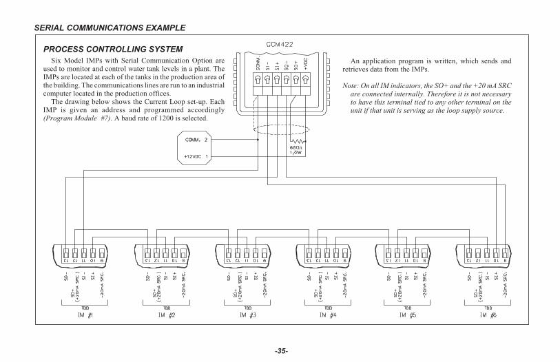
SERIAL COMMUNICATIONS EXAMPLE
-35-
An application program is written, which sends andretrieves data from the IMPs.
Note: On all IM indicators, the SO+ and the +20 mA SRCare connected internally. Therefore it is not necessaryto have this terminal tied to any other terminal on theunit if that unit is serving as the loop supply source.
PROCESS CONTROLLING SYSTEM
Six Model IMPs with Serial Communication Option areused to monitor and control water tank levels in a plant. TheIMPs are located at each of the tanks in the production area ofthe building. The communications lines are run to an industrialcomputer located in the production offices.
The drawing below shows the Current Loop set-up. EachIMP is given an address and programmed accordingly(Program Module #7). A baud rate of 1200 is selected.
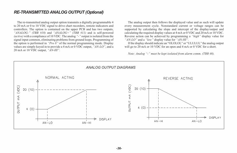
RE-TRANSMITTED ANALOG OUTPUT (Optional)
The re-transmitted analog output option transmits a digitally programmable 4to 20 mA or 0 to 10 VDC signal to drive chart recorders, remote indicators andcontrollers. The option is contained on the upper PCB and has two outputs,“ANALOG-” (TBB #10) and “ANALOG+” (TBB #11) and is self-powered(active) with a compliance of 10 VDC. The analog “-” output is isolated from thesignal input common, eliminating problems from ground loops. Programming ofthe option is performed in “Pro 8” of the normal programming mode. Displayvalues are simply keyed in to provide a 4 mA or 0 VDC output, “AN-LO”, and a20 mA or 10 VDC output, “AN-HI”.
The analog output then follows the displayed value and as such will updateevery measurement cycle. Nonstandard current or voltage ranges can besupported by calculating the slope and intercept of the display/output andcalculating the required display values at 4 mA or 0 VDC and 20 mA or 10 VDC.Reverse action can be achieved by programming a “high” display value for“AN-LO” and a “low” display value for “AN-HI”.
If the display should indicate an “OLOLOL” or “ULULUL” the analog outputwill go to 20 mA or 10 VDC for an open and 4 mA or 0 VDC for a short.
Note: Analog “-” must be kept isolated from alarm comm. (TBB #8).
-36-
ANALOG OUTPUT DIAGRAMS
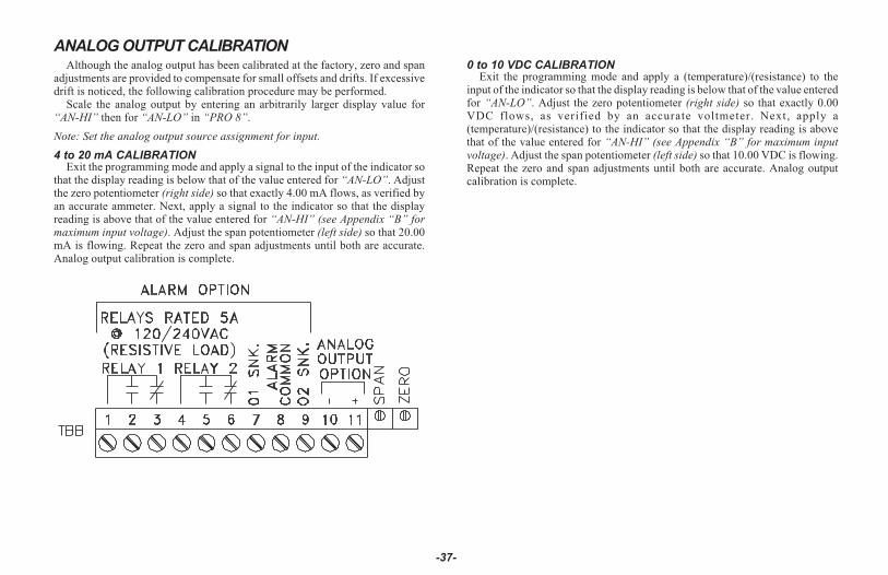
ANALOG OUTPUT CALIBRATIONAlthough the analog output has been calibrated at the factory, zero and span
adjustments are provided to compensate for small offsets and drifts. If excessivedrift is noticed, the following calibration procedure may be performed.
Scale the analog output by entering an arbitrarily larger display value for“AN-HI” then for “AN-LO” in “PRO 8”.
Note: Set the analog output source assignment for input.
4 to 20 mA CALIBRATIONExit the programming mode and apply a signal to the input of the indicator so
that the display reading is below that of the value entered for “AN-LO”. Adjustthe zero potentiometer (right side) so that exactly 4.00 mA flows, as verified byan accurate ammeter. Next, apply a signal to the indicator so that the displayreading is above that of the value entered for “AN-HI” (see Appendix “B” formaximum input voltage). Adjust the span potentiometer (left side) so that 20.00mA is flowing. Repeat the zero and span adjustments until both are accurate.Analog output calibration is complete.
0 to 10 VDC CALIBRATIONExit the programming mode and apply a (temperature)/(resistance) to the
input of the indicator so that the display reading is below that of the value enteredfor “AN-LO”. Adjust the zero potentiometer (right side) so that exactly 0.00VDC flows, as verified by an accurate voltmeter. Next, apply a(temperature)/(resistance) to the indicator so that the display reading is abovethat of the value entered for “AN-HI” (see Appendix “B” for maximum inputvoltage). Adjust the span potentiometer (left side) so that 10.00 VDC is flowing.Repeat the zero and span adjustments until both are accurate. Analog outputcalibration is complete.
-37-
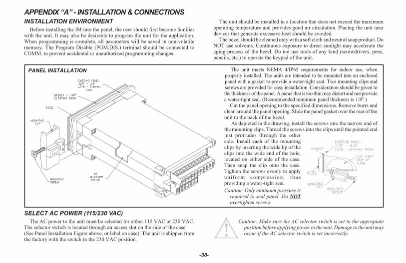
-38-
The unit meets NEMA 4/IP65 requirements for indoor use, whenproperly installed. The units are intended to be mounted into an enclosedpanel with a gasket to provide a water-tight seal. Two mounting clips andscrews are provided for easy installation. Consideration should be given tothe thickness of the panel. A panel that is too thin may distort and not providea water-tight seal. (Recommended minimum panel thickness is 1/8".)
Cut the panel opening to the specified dimensions. Remove burrs andclean around the panel opening. Slide the panel gasket over the rear of theunit to the back of the bezel.
As depicted in the drawing, install the screws into the narrow end ofthe mounting clips. Thread the screws into the clips until the pointed endjust protrudes through the otherside. Install each of the mountingclips by inserting the wide lip of theclips into the wide end of the hole,located on either side of the case.Then snap the clip onto the case.Tighten the screws evenly to applyuniform compress ion, thusproviding a water-tight seal.
Caution: Only minimum pressure isrequired to seal panel. Do NOT
overtighten screws.
APPENDIX “A” - INSTALLATION & CONNECTIONS
INSTALLATION ENVIRONMENT
Before installing the IM into the panel, the user should first become familiarwith the unit. It may also be desirable to program the unit for the application.When programming is complete, all parameters will be saved in non-volatilememory. The Program Disable (PGM.DIS.) terminal should be connected toCOMM. to prevent accidental or unauthorized programming changes.
The unit should be installed in a location that does not exceed the maximumoperating temperature and provides good air circulation. Placing the unit neardevices that generate excessive heat should be avoided.
The bezel should be cleaned only with a soft cloth and neutral soap product. DoNOT use solvents. Continuous exposure to direct sunlight may accelerate theaging process of the bezel. Do not use tools of any kind (screwdrivers, pens,pencils, etc.) to operate the keypad of the unit.
PANEL INSTALLATION
SELECT AC POWER (115/230 VAC)
The AC power to the unit must be selected for either 115 VAC or 230 VAC.The selector switch is located through an access slot on the side of the case(See Panel Installation Figure above, or label on case). The unit is shipped fromthe factory with the switch in the 230 VAC position.
Caution: Make sure the AC selector switch is set to the appropiateposition before applying power to the unit. Damage to the unit mayoccur if the AC selector switch is set incorrectly.
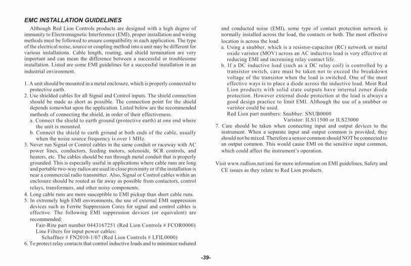
EMC INSTALLATION GUIDELINES
Although Red Lion Controls products are designed with a high degree ofimmunity to Electromagnetic Interference (EMI), proper installation and wiringmethods must be followed to ensure compatibility in each application. The typeof the electrical noise, source or coupling method into a unit may be different forvarious installations. Cable length, routing, and shield termination are veryimportant and can mean the difference between a successful or troublesomeinstallation. Listed are some EMI guidelines for a successful installation in anindustrial environment.
1. A unit should be mounted in a metal enclosure, which is properly connected toprotective earth.
2. Use shielded cables for all Signal and Control inputs. The shield connectionshould be made as short as possible. The connection point for the shielddepends somewhat upon the application. Listed below are the recommendedmethods of connecting the shield, in order of their effectiveness.a. Connect the shield to earth ground (protective earth) at one end where
the unit is mounted.b. Connect the shield to earth ground at both ends of the cable, usually
when the noise source frequency is over 1 MHz.3. Never run Signal or Control cables in the same conduit or raceway with AC
power lines, conductors, feeding motors, solenoids, SCR controls, andheaters, etc. The cables should be run through metal conduit that is properlygrounded. This is especially useful in applications where cable runs are longand portable two-way radios are used in close proximity or if the installation isnear a commercial radio transmitter. Also, Signal or Control cables within anenclosure should be routed as far away as possible from contactors, controlrelays, transformers, and other noisy components.
4. Long cable runs are more susceptible to EMI pickup than short cable runs.5. In extremely high EMI environments, the use of external EMI suppression
devices such as Ferrite Suppression Cores for signal and control cables iseffective. The following EMI suppression devices (or equivalent) arerecommended:
Fair-Rite part number 0443167251 (Red Lion Controls # FCOR0000)Line Filters for input power cables:
Schaffner # FN2010-1/07 (Red Lion Controls # LFIL0000)6. To protect relay contacts that control inductive loads and to minimize radiated
and conducted noise (EMI), some type of contact protection network isnormally installed across the load, the contacts or both. The most effectivelocation is across the load.a. Using a snubber, which is a resistor-capacitor (RC) network or metal
oxide varistor (MOV) across an AC inductive load is very effective atreducing EMI and increasing relay contact life.
b. If a DC inductive load (such as a DC relay coil) is controlled by atransistor switch, care must be taken not to exceed the breakdownvoltage of the transistor when the load is switched. One of the mosteffective ways is to place a diode across the inductive load. Most RedLion products with solid state outputs have internal zener diodeprotection. However external diode protection at the load is always agood design practice to limit EMI. Although the use of a snubber orvaristor could be used.Red Lion part numbers: Snubber: SNUB0000
Varistor: ILS11500 or ILS230007. Care should be taken when connecting input and output devices to the
instrument. When a separate input and output common is provided, theyshould not be mixed. Therefore a sensor common should NOT be connected to an output common. This would cause EMI on the sensitive input common,which could affect the instrument’s operation.
Visit www.redlion.net/emi for more information on EMI guidelines, Safety andCE issues as they relate to Red Lion products.
-39-

WIRING CONNECTIONS
After the unit has been mechanically mounted, it is ready to be wired. Allconductors should meet voltage and current ratings for each terminal. Alsocabling should conform to appropriate standards of good installation, local codesand regulations. It is recommended that power supplied to the unit be protectedby a fuse or circuit breaker. All wiring connections are made on removableplug-in terminal blocks. There is a separate terminal block for the bottom board(TBA) and optional top board (TBB). When wiring the unit, remove the terminalblock and use the numbers on the label to identify the position number with theproper function. Strip the wire, leaving approximately 1/4" bare wire exposed(stranded wires should be tinned with solder). Insert the wire into the terminaland tighten down the screw until the wire is clamped tightly. Be sure all wires areclean and the connections are tight to ensure good conductivity. Each terminalcan accept up to one 14-gage, two 18-gage or four 20-gage wire(s). After theterminal block is wired, install it into the proper location on the PC board. Wireeach terminal block in this manner.
POWER WIRING
Primary AC power is connected to TBA #1 and 2 (marked VAC 50/60 HZ,located on the left hand side of the bottom terminal block). To reduce the chance ofnoise spikes entering the AC line and affecting the indicator, the AC power should
be relatively “clean” and within the specified 10% variation limit. Drawingpower from heavily loaded circuits or circuits which also power loads that cycle onand off, (contactors, relays, motors, machinery, etc.) should be avoided.
USER INPUT WIRING
User inputs (PGM.DIS., E1-CON, and optional E2-CON) are digital inputsthat are active when connected to TBA #5 Common. Any form of mechanicalswitch, sinking open collector logic with less than 0.7 V saturation may be used.The use of shielded cable is recommended. Follow the Additional EMCInstallation Guidelines for shield connection.
OUTPUT WIRING
RELAY CONNECTIONS
To prolong contact life and suppress electrical noise interference due to theswitching of inductive loads, it is good installation practice to install a snubberacross the contactor. Follow the manufacturer’s instructions for installation.Note: Snubber leakage current can cause some electro-mechanical devices to be
held ON.
-40-

SIGNAL WIRING
Meter signal input common is not isolated from PGM.DIS,E1-CON, E2-CON, and +EXC. Maximum allowable 50 V can bepresent in the circuit that is being measured.
Two Wire Transducers Requiring Excitation:Connect the “+” lead of the transducer to TBA #7, “+EXCITATION”, and the
“-” lead to TBA #6, “+SIGNAL”. Refer to the transducer manufacturer’s datasheet supplied with the transducer for proper connections.Note: The common of the excitation voltage is connected internally to “COMM”
(TBA #5).
-41-
A.C. Power Basic Connection
A.C. Power Basic Connection w/Internal 18 V Excitation
For Signal Sources Not Requiring Excitation:Connect the “+” lead of the process signal to TBA #6, “+SIGNAL”, and the
“-” lead of the signal to TBA #5, “COMM”. Regardless of the signal level of theprocess (4 to 20 mA or 10 to 50 mA, etc.), the indicator automatically adapts tothe proper range. Refer to the transducer manufacturer’s data sheet suppliedwith the transducer for proper connections.
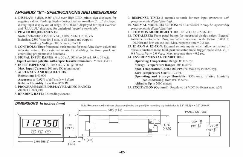
APPENDIX “B” - SPECIFICATIONS AND DIMENSIONS1. DISPLAY: 6-digit, 0.56" (14.2 mm) High LED, minus sign displayed for
negative values. Flashing display during totalizer overflow. “......” displayedduring input display out of range. “OLOLOL” displayed for input overloadand “ULULUL” displayed for underload (negative overload).
2. POWER REQUIREMENTS:
Switch Selectable 115/230 VAC, 10%, 50/60 Hz, 14 VAIsolation: 2300 Vrms for 1 min. to all inputs and outputs.
Working Voltage: 300 V max., CAT II3. CONTROLS: Three front panel push buttons for modifying alarm values and
indicator set-up. Two external inputs for disabling the front panel andcontrolling programmable functions.
4. SIGNAL INPUT RANGE: 0 to 50 mA DC (4 to 20 mA, 10 to 50 mA)Input Common potential with respect to earth Common: 50 V max., CAT I
5. INPUT IMPEDANCE: 10 �, 0.2 VDC @ 20 mAMax. Input Current: 200 mA DC (continuous)
6. ACCURACY AND RESOLUTION:
Resolution: 1/40,000
Accuracy: (0.02% of full scale + 1 digit)Relative Humidity: Less than 85% RH
7. PROGRAMMABLE DISPLAY READING RANGE:
-99,999 to 999,9998. READING RATE: 2.5 readings/second
9. RESPONSE TIME: 2 seconds to settle for step input (increases withprogrammable digital filtering).
10. NORMAL MODE REJECTION: 40 dB at 50/60 Hz (may be improved byprogrammable digital filtering)
11. COMMON MODE REJECTION: 120 dB, DC to 50/60 Hz12. TOTALIZER: Front panel button for input/total display select. External
totalizer reset/enable. Programmable time-base, scale factor (0.001 to100.000) and low-end cut-out. Max. response time = 0.2 sec.
13. E1-CON & E2-CON: External remote inputs which allow activation ofvarious functions (reset total, peak indicator mode, trigger mode, etc.). VIL =0.8 VMAX; VIN = 2.0 VMIN; Max. response time = 0.2 sec.
14. ENVIRONMENTAL CONDITIONS:
Operating Temperature Range: 0� to 50�C
Storage Temperature Range: -40� to 80�C
Span Temperature Coeff.: 100 PPM/°C max.; 40 PPM/�C typ.
Zero Temperature Coeff.: 1 V/�COperating and Storage Humidity: 85% max. relative humidity
(non-condensing) from 0°C to 50°C.Altitude: Up to 2000 meters
15. EXCITATION (Optional): Regulated 18 VDC @ 60 mA max. ��
-42-
DIMENSIONS In inches (mm)Note: Recommended minimum clearance (behind the panel) for mounting clip installation is 2.1" (53.3) H x 5.5" (140) W.
PANEL CUT-OUT
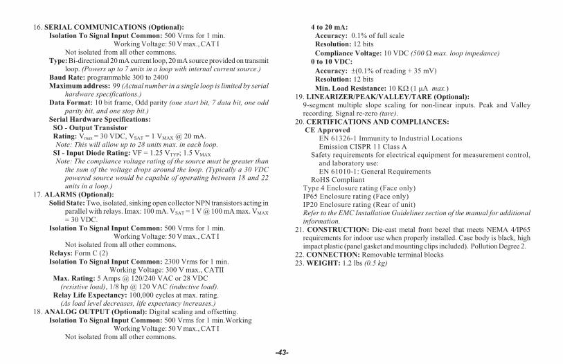
16. SERIAL COMMUNICATIONS (Optional):Isolation To Signal Input Common: 500 Vrms for 1 min.
Working Voltage: 50 V max., CAT INot isolated from all other commons.
Type: Bi-directional 20 mA current loop, 20 mA source provided on transmit loop. (Powers up to 7 units in a loop with internal current source.)
Baud Rate: programmable 300 to 2400Maximum address: 99 (Actual number in a single loop is limited by serial
hardware specifications.)Data Format: 10 bit frame, Odd parity (one start bit, 7 data bit, one odd
parity bit, and one stop bit.)Serial Hardware Specifications:
SO - Output TransistorRating: Vmax = 30 VDC, VSAT = 1 VMAX @ 20 mA.
Note: This will allow up to 28 units max. in each loop.SI - Input Diode Rating: VF = 1.25 VTYP; 1.5 VMAX
Note: The compliance voltage rating of the source must be greater thanthe sum of the voltage drops around the loop. (Typically a 30 VDCpowered source would be capable of operating between 18 and 22units in a loop.)
17. ALARMS (Optional):Solid State: Two, isolated, sinking open collector NPN transistors acting in
parallel with relays. Imax: 100 mA. VSAT = 1 V @ 100 mA max. VMAX
= 30 VDC.Isolation To Signal Input Common: 500 Vrms for 1 min.
Working Voltage: 50 V max., CAT INot isolated from all other commons.
Relays: Form C (2) Isolation To Signal Input Common: 2300 Vrms for 1 min.
Working Voltage: 300 V max., CATIIMax. Rating: 5 Amps @ 120/240 VAC or 28 VDC (resistive load), 1/8 hp @ 120 VAC (inductive load).Relay Life Expectancy: 100,000 cycles at max. rating. (As load level decreases, life expectancy increases.)
18. ANALOG OUTPUT (Optional): Digital scaling and offsetting.Isolation To Signal Input Common: 500 Vrms for 1 min.Working
Working Voltage: 50 V max., CAT INot isolated from all other commons.
4 to 20 mA:Accuracy: 0.1% of full scaleResolution: 12 bitsCompliance Voltage: 10 VDC (500 W max. loop impedance)
0 to 10 VDC:Accuracy: ±(0.1% of reading + 35 mV)Resolution: 12 bitsMin. Load Resistance: 10 KW (1 mA max.)
19. LINEARIZER/PEAK/VALLEY/TARE (Optional):9-segment multiple slope scaling for non-linear inputs. Peak and Valleyrecording. Signal re-zero (tare).
20. CERTIFICATIONS AND COMPLIANCES: CE Approved
EN 61326-1 Immunity to Industrial LocationsEmission CISPR 11 Class A
Safety requirements for electrical equipment for measurement control,and laboratory use:EN 61010-1: General Requirements
RoHS CompliantType 4 Enclosure rating (Face only)IP65 Enclosure rating (Face only)IP20 Enclosure rating (Rear of unit)Re fer to the EMC In stal la tion Guide lines sec tion of the man ual for ad di tionalin for ma tion.
21. CONSTRUCTION: Die-cast metal front bezel that meets NEMA 4/IP65requirements for indoor use when properly installed. Case body is black, highimpact plastic (panel gasket and mounting clips included). Pollution Degree 2.
22. CONNECTION: Removable terminal blocks23. WEIGHT: 1.2 lbs (0.5 kg)
-43-

-44-
APPENDIX “C” - TROUBLESHOOTING GUIDE
The majority of all problems with the indicator can be traced to improper connections or improperprogramming set-ups. Be sure all connections are clean and tight and check the programming set-ups forcorrect data.
For further technical assistance, contact technical support at www.redlion.net.
PROBLEM POSSIBLE CAUSE REMEDIES
NO DISPLAY 1. Power off, improperly connected, or brown-out. 1a. Check wiring. b. Verify power.
“PPPPPP” IN DISPLAY 1. Program data error. 1. Press “P” and Check data set-ups.
FLASHING DISPLAY 1. Totalizer overflow. 1. Reset totalizer.
“......” IN DISPLAY 1. Input display out of range.
2. Loss of data set-ups.
1a. Check unit scaling. b. Check for electrical disturbance.2a. Check data set-ups. b. Check for electrical disturbance. c. Disconnect and reconnect power.
DISPLAY WANDERS 1. Loss of data set-ups. 1a. Check data set-ups. b. Disconnect and reconnect power. c. Check for electrical disturbance.
JITTERY DISPLAY 1. Electrical “Noise” in process or signal lines.
2. Process inherently unstable.
1a. Increase digital filtering. b. Increase display rounding increment. c. Re-route signal wires.2. Dampen process to eliminate oscillations.
“ULULUL” IN DISPLAY 1. Input Underload (negative overload). 1. Check input levels.
“OLOLOL” IN DISPLAY 1. Input overload. 1. Check input levels.
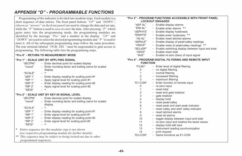
APPENDIX “D” - PROGRAMMABLE FUNCTIONS
-45-
Programming of the indicator is divided into modular steps. Each module is ashort sequence of data entries. The front panel buttons “UP” and “DOWN”,(shown as “arrows” on the front panel) are used to change the data and set-ups,while the “P” button is used to save or enter the data. After pressing “P” whichgains entry into the programming mode, the programming modules areidentified by the message “Pro” and a number in the display. “UP” and“DOWN” are used to select the desired programming module and “P” is used to enter it. All of the subsequent programming steps follow the same procedure.The rear terminal labeled “PGM. DIS.” must be ungrounded to gain access toprogramming. The following table lists the programming steps.
“Pro 0” - RETURN TO MEASUREMENT MODE
“Pro 1” - SCALE UNIT BY APPLYING SIGNAL
“dECPNt” Enter decimal point for scaled display“round” Enter rounding factor and trailing zeros for scaled
display“SCALE” *“dSP 1” Enter display reading for scaling point #1“INP 1” Apply signal level for scaling point #1“dSP 2” Enter display reading for scaling point #2“INP 2” Apply signal level for scaling point #2“SEGt” *
“Pro 2” - SCALE UNIT BY KEY-IN SIGNAL LEVEL
“dECPNt” Enter decimal point for scaled display“round” Enter rounding factor and trailing zeros for scaled
display“SCALE” *“dSP 1” Enter display reading for scaling point #1“INP 1” Enter signal level for scaling point #1“dSP 2” Enter display reading for scaling point #2“INP 2” Enter signal level for scaling point #2“SEGt” *
* Entire sequence for this modular step is not shown (see respective programming module for further details).
** This sequence may be subject to being locked-out due to other programmed sequences.
“Pro 3” - PROGRAM FUNCTIONS ACCESSIBLE WITH FRONT PANEL LOCKOUT ENGAGED
“dSP AL” Enable display alarms“ENt AL” Enable enter alarms **
“dSPHYS” Enable display hysteresis“ENtHYS” Enable enter hysteresis **“rSt AL” Enable reset latched alarms
“dSPbUF” Enable display of peak/valley readings“rStbUF” Enable reset of peak/valley readings **
“SELdSP” Enable switching display between input and total“rSttOt” Enable reset total“tArE” Enable re-zero (tare) of input signal
“Pro 4” - PROGRAM DIGITAL FILTERING AND REMOTE INPUT FUNCTION
“FILtEr” Enter level of digital filtering0 no digital filtering1 normal filtering2 increased filtering3 maximum filtering
“E1-CON” Enter function of remote input 0 re-zero input1 reset total2 reset and gate totalizer3 gate totalizer4 display hold5 reset peak/valley6 reset peak and start peak indicator7 reset valley and start valley indicator8 reset latched alarms9 reset all alarms
10 toggle display between input and total11 re-zero input and totalize the tared values12 display hold with tare13 Instrument reading synchronization14 print request
“E2-CON” Same functions as E1-CON
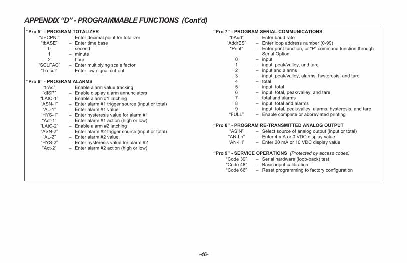
-46-
APPENDIX “D” - PROGRAMMABLE FUNCTIONS (Cont’d)
“Pro 5” - PROGRAM TOTALIZER
“dECPNt” Enter decimal point for totalizer“tbASE” Enter time base
0 second1 minute2 hour
“SCLFAC” Enter multiplying scale factor“Lo-cut” Enter low-signal cut-out
“Pro 6” - PROGRAM ALARMS
“trAc” Enable alarm value tracking“dISP” Enable display alarm annunciators
“LAtC-1” Enable alarm #1 latching“ASN-1” Enter alarm #1 trigger source (input or total)“AL-1” Enter alarm #1 value
“HYS-1” Enter hysteresis value for alarm #1“Act-1” Enter alarm #1 action (high or low)
“LAtC-2” Enable alarm #2 latching“ASN-2” Enter alarm #2 trigger source (input or total)“AL-2” Enter alarm #2 value
“HYS-2” Enter hysteresis value for alarm #2“Act-2” Enter alarm #2 action (high or low)
“Pro 7” - PROGRAM SERIAL COMMUNICATIONS
“bAud” Enter baud rate“AddrES” Enter loop address number (0-99)
“Print” Enter print function, or “P” command function throughSerial Option
0 input1 input, peak/valley, and tare2 input and alarms3 input, peak/valley, alarms, hysteresis, and tare4 total5 input, total6 input, total, peak/valley, and tare7 total and alarms8 input, total and alarms9 input, total, peak/valley, alarms, hysteresis, and tare
“FULL” Enable complete or abbreviated printing
“Pro 8” - PROGRAM RE-TRANSMITTED ANALOG OUTPUT
“ASIN” Select source of analog output (input or total)“AN-Lo” Enter 4 mA or 0 VDC display value“AN-HI” Enter 20 mA or 10 VDC display value
“Pro 9” - SERVICE OPERATIONS (Protected by access codes)
“Code 39” Serial hardware (loop-back) test“Code 48” Basic input calibration“Code 66” Reset programming to factory configuration

APPENDIX “E” - USERS PROGRAMMING VALUES CHART
PROGRAM MODULE #1
Scaled By Signal Method
dECPNt
round
SCALE
dSP 1
INP 1
dSP 2
INP 2
Ad di tional scal ing points are NOT nec es sary, un less multi- segment line ari za tion is re quired.
dSP 3
INP 3
dSP 4
INP 4
dSP 5
INP 5
dSP 6
INP 6
dSP 7
INP 7
dSP 8
INP 8
dSP 9
INP 9
PROGRAM MODULE #2
Scaled By Signal Method
dECPNt
round
SCALE
dSP 1
INP 1
dSP 2
INP 2
Ad di tional scal ing points are NOT nec es sary,un less multi- segment line ari za tion is re quired.
dSP 3
INP 3
dSP 4
INP 4
dSP 5
INP 5
dSP 6
INP 6
dSP 7
INP 7
dSP 8
INP 8
dSP 9
INP 9
-47-

APPENDIX “E” - USERS PROGRAMMING VALUES CHART
PROGRAM MODULE #3
Front Panel Lockout
dSP AL
Ent AL
dSPHYS
ENtHYS
rSt AL
dSPbUF
rStbUF
SELdSP
RSttOt
tArE
PROGRAM MODULE #4
Digital Filter & Remote Input Function
FILtER
E1-CON
E2-CON
PROGRAM MODULE #5
Integrator/Totalizer
dECPNt
tdASE
SCLFAC
Lo-cut
PRO GRAM MOD ULE #6
Alarms
trAC
dISP
LAtC-1
ASN-1
AL-1
HyS-1
Act-1
LAtC-2
ASN-2
AL-2
HyS-2
Act-2
PRO GRAM MOD ULE #7
Communications
bAud
AddrES
FULL
PRO GRAM MOD ULE #8
Analog Output
ASIN
AN-Lo
AN-HI
-48-
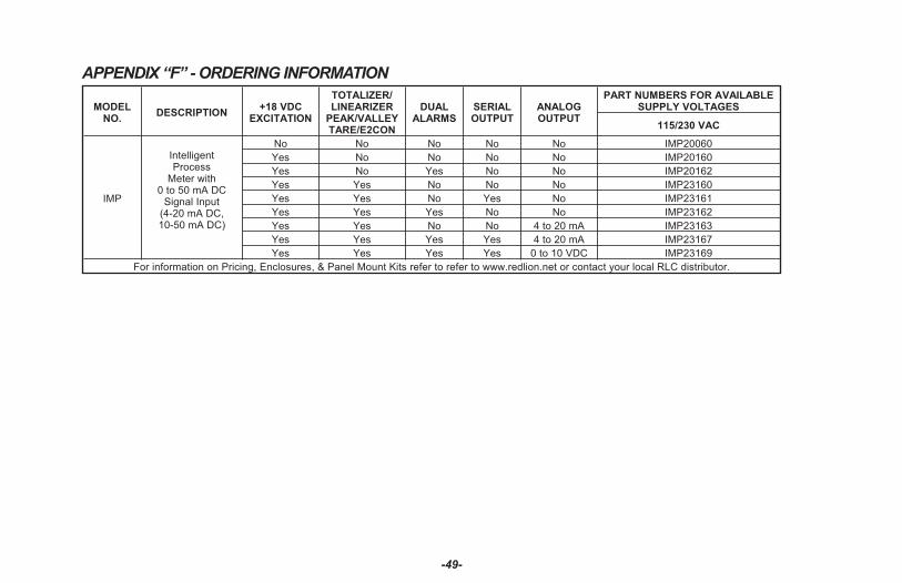
-49-
APPENDIX “F” - ORDERING INFORMATION
MODELNO.
DESCRIPTION+18 VDC
EXCITATION
TOTALIZER/LINEARIZER
PEAK/VALLEYTARE/E2CON
DUALALARMS
SERIALOUTPUT
ANALOGOUTPUT
PART NUMBERS FOR AVAILABLESUPPLY VOLTAGES
115/230 VAC
IMP
IntelligentProcess
Meter with0 to 50 mA DC
Signal Input(4-20 mA DC,10-50 mA DC)
No No No No No IMP20060
Yes No No No No IMP20160
Yes No Yes No No IMP20162
Yes Yes No No No IMP23160
Yes Yes No Yes No IMP23161
Yes Yes Yes No No IMP23162
Yes Yes No No 4 to 20 mA IMP23163
Yes Yes Yes Yes 4 to 20 mA IMP23167
Yes Yes Yes Yes 0 to 10 VDC IMP23169
For information on Pricing, Enclosures, & Panel Mount Kits refer to re fer to www.redlion.net or contact your local RLC distributor.

LIMITED WARRANTY(a) Red Lion Controls Inc. (the “Company”) warrants that all Products shall be free from defects in material and workmanship under normal use for the period of time provided in “Statement of Warranty Periods” (available at www.redlion.net) current at the time of shipment of the Products (the “Warranty Period”). EXCEPT FOR THE ABOVE-STATED WARRANTY, COMPANY MAKES NO WARRANTY WHATSOEVER WITH RESPECT TO THE PRODUCTS, INCLUDING ANY (A) WARRANTY OF MERCHANTABILITY; (B) WARRANTY OF FITNESS FOR A PARTICULAR PURPOSE; OR (C) WARRANTY AGAINST INFRINGEMENT OF INTELLECTUAL PROPERTY RIGHTS OF A THIRD PARTY; WHETHER EXPRESS OR IMPLIED BY LAW, COURSE OF DEALING, COURSE OF PERFORMANCE, USAGE OF TRADE OR OTHERWISE. Customer shall be responsible for determining that a Product is suitable for Customer’s use and that such use complies with any applicable local, state or federal law. (b) The Company shall not be liable for a breach of the warranty set forth in paragraph (a) if (i) the defect is a result of Customer’s failure to store, install, commission or maintain the Product according to specifications; (ii) Customer alters or repairs such Product without the prior written consent of Company.(c) Subject to paragraph (b), with respect to any such Product during the Warranty Period, Company shall, in its sole discretion, either (i) repair or replace the Product; or (ii) credit or refund the price of Product provided that, if Company so requests, Customer shall, at Company’s expense, return such Product to Company.(d) THE REMEDIES SET FORTH IN PARAGRAPH (c) SHALL BE THE CUSTOMER’S SOLE AND EXCLUSIVE REMEDY AND COMPANY’S ENTIRE LIABILITY FOR ANY BREACH OF THE LIMITED WARRANTY SET FORTH IN PARAGRAPH (a).

IMP / IM - R 10/17DRAWING NO. LP0183