the apollo intelligent meter series · 2018-08-14 · the apollo intelligent meter for decade volts...
TRANSCRIPT

THE APOLLO INTELLIGENT METER SERIES
MODEL IMD1 INSTRUCTION MANUAL

INTRODUCTIONThe Intelligent Meter for Decade Volt (DC) Inputs (IMD1) is another unit in our
multi-purpose series of industrial control products that is field-programmable to solve multiple applications. This series of products is built around the concept that the end user has the capability to program different personalities and functions into the unit in order to adapt to different indication and control requirements.
The Intelligent Meter which you have purchased has the same high quality workmanship and advanced technological capabilities that have made Red Lion Controls the leader in today’s industrial market.
Red Lion Controls has a complete line of industrial indication and control equipment, and we look forward to being of service to you now and in the future.
CAUTION: Read complete instructions prior to installation
and operation of the unit.
CAUTION: Risk of electric shock.

Table of Contents
SAFETY INFORMATION · · · · · · · · · · · · · · · · · · · · · · · · · · · · · · · · · · · · · · · · · · · · · · · · · · · · · · · · · · · · · · 3Safety Summary · · · · · · · · · · · · · · · · · · · · · · · · · · · · · · · · · · · · · · · · · · · · · · · · · · · · · · · · · · · · · · · · · · · 3
GENERAL DESCRIPTION · · · · · · · · · · · · · · · · · · · · · · · · · · · · · · · · · · · · · · · · · · · · · · · · · · · · · · · · · · · · · 4Theory Of Operation · · · · · · · · · · · · · · · · · · · · · · · · · · · · · · · · · · · · · · · · · · · · · · · · · · · · · · · · · · · · · · · 4Block Diagram · · · · · · · · · · · · · · · · · · · · · · · · · · · · · · · · · · · · · · · · · · · · · · · · · · · · · · · · · · · · · · · · · · · · 5
PROGRAMMING AND OPERATING THE IMD1 · · · · · · · · · · · · · · · · · · · · · · · · · · · · · · · · · · · · · · · · · · · 6Programming the IMD1 · · · · · · · · · · · · · · · · · · · · · · · · · · · · · · · · · · · · · · · · · · · · · · · · · · · · · · · · · · · · · 6Module #1 - Scale By Signal Level Method · · · · · · · · · · · · · · · · · · · · · · · · · · · · · · · · · · · · · · · · · · · · · 8Module #2 - Scale By Key-In Method · · · · · · · · · · · · · · · · · · · · · · · · · · · · · · · · · · · · · · · · · · · · · · · · · 10Module #3 - Program Functions Accessible With Front Panel Lockout · · · · · · · · · · · · · · · · · · · · · 11Module #4 - Program Digital Filter And Remote Input · · · · · · · · · · · · · · · · · · · · · · · · · · · · · · · · · · · 13Module #5 - Program Integrator/Totalizer · · · · · · · · · · · · · · · · · · · · · · · · · · · · · · · · · · · · · · · · · · · · · 15Module #6 - Program Alarm/Setpoint · · · · · · · · · · · · · · · · · · · · · · · · · · · · · · · · · · · · · · · · · · · · · · · · · 16Module #7 - Program Serial Communications · · · · · · · · · · · · · · · · · · · · · · · · · · · · · · · · · · · · · · · · · · 18Module #8 - Program Re-Transmitted Analog Output · · · · · · · · · · · · · · · · · · · · · · · · · · · · · · · · · · · 19Module #9 - Service Operations · · · · · · · · · · · · · · · · · · · · · · · · · · · · · · · · · · · · · · · · · · · · · · · · · · · · · 20Operating the IMD1 · · · · · · · · · · · · · · · · · · · · · · · · · · · · · · · · · · · · · · · · · · · · · · · · · · · · · · · · · · · · · · · 21Quick Programming · · · · · · · · · · · · · · · · · · · · · · · · · · · · · · · · · · · · · · · · · · · · · · · · · · · · · · · · · · · · · · · 21Factory Configuration · · · · · · · · · · · · · · · · · · · · · · · · · · · · · · · · · · · · · · · · · · · · · · · · · · · · · · · · · · · · · 22Programming Example · · · · · · · · · · · · · · · · · · · · · · · · · · · · · · · · · · · · · · · · · · · · · · · · · · · · · · · · · · · · 23Pneumatic Pressure Example · · · · · · · · · · · · · · · · · · · · · · · · · · · · · · · · · · · · · · · · · · · · · · · · · · · · · · · 24
EXCITATION (Optional) · · · · · · · · · · · · · · · · · · · · · · · · · · · · · · · · · · · · · · · · · · · · · · · · · · · · · · · · · · · · · · 25
TOTALIZER/LINEARIZER/PEAK/VALLEY/TARE (Optional) · · · · · · · · · · · · · · · · · · · · · · · · · · · · · · · 25Totalizer · · · · · · · · · · · · · · · · · · · · · · · · · · · · · · · · · · · · · · · · · · · · · · · · · · · · · · · · · · · · · · · · · · · · · · · · 25Totalizer Example · · · · · · · · · · · · · · · · · · · · · · · · · · · · · · · · · · · · · · · · · · · · · · · · · · · · · · · · · · · · · · · · 25
Basic Set-up · · · · · · · · · · · · · · · · · · · · · · · · · · · · · · · · · · · · · · · · · · · · · · · · · · · · · · · · · · · · · · · · · · 25Totalizer Set-up · · · · · · · · · · · · · · · · · · · · · · · · · · · · · · · · · · · · · · · · · · · · · · · · · · · · · · · · · · · · · · · 25
Linearizer · · · · · · · · · · · · · · · · · · · · · · · · · · · · · · · · · · · · · · · · · · · · · · · · · · · · · · · · · · · · · · · · · · · · · · · 26Linear Segmenting Example · · · · · · · · · · · · · · · · · · · · · · · · · · · · · · · · · · · · · · · · · · · · · · · · · · · · · · · · 27Peak/Valley · · · · · · · · · · · · · · · · · · · · · · · · · · · · · · · · · · · · · · · · · · · · · · · · · · · · · · · · · · · · · · · · · · · · · · 28Tare · · · · · · · · · · · · · · · · · · · · · · · · · · · · · · · · · · · · · · · · · · · · · · · · · · · · · · · · · · · · · · · · · · · · · · · · · · · · 28
ALARMS (Optional) · · · · · · · · · · · · · · · · · · · · · · · · · · · · · · · · · · · · · · · · · · · · · · · · · · · · · · · · · · · · · · · · · 29
-1-
20 mA CURRENT LOOP SERIAL COMMUNICATIONS (Optional) · · · · · · · · · · · · · · · · · · · · · · · · 30General Description · · · · · · · · · · · · · · · · · · · · · · · · · · · · · · · · · · · · · · · · · · · · · · · · · · · · · · · · · 30Communication Format · · · · · · · · · · · · · · · · · · · · · · · · · · · · · · · · · · · · · · · · · · · · · · · · · · · · · · 30Sending Commands to the IMD1 · · · · · · · · · · · · · · · · · · · · · · · · · · · · · · · · · · · · · · · · · · · · · · · 31
Command String Examples · · · · · · · · · · · · · · · · · · · · · · · · · · · · · · · · · · · · · · · · · · · · · · · · · 31Receiving Data from the IMD1 · · · · · · · · · · · · · · · · · · · · · · · · · · · · · · · · · · · · · · · · · · · · · · · · · 33
CURRENT LOOP INSTALLATION · · · · · · · · · · · · · · · · · · · · · · · · · · · · · · · · · · · · · · · · · · · · · · · · 34Wiring Connections · · · · · · · · · · · · · · · · · · · · · · · · · · · · · · · · · · · · · · · · · · · · · · · · · · · · · · · · · 34Serial Terminal Descriptions · · · · · · · · · · · · · · · · · · · · · · · · · · · · · · · · · · · · · · · · · · · · · · · · · · · 34Serial Communications Example · · · · · · · · · · · · · · · · · · · · · · · · · · · · · · · · · · · · · · · · · · · · · · · 35
Process Controlling System · · · · · · · · · · · · · · · · · · · · · · · · · · · · · · · · · · · · · · · · · · · · · · · · 35
RE-TRANSMITTED ANALOG OUTPUT (Optional) · · · · · · · · · · · · · · · · · · · · · · · · · · · · · · · · · · · · 36Analog Output Calibration · · · · · · · · · · · · · · · · · · · · · · · · · · · · · · · · · · · · · · · · · · · · · · · · · · · · 37
APPENDIX “A” - INSTALLATION & CONNECTIONS · · · · · · · · · · · · · · · · · · · · · · · · · · · · · · · · · · 38Installation Environment · · · · · · · · · · · · · · · · · · · · · · · · · · · · · · · · · · · · · · · · · · · · · · · · · · · · · · 38
Panel In stal la tion · · · · · · · · · · · · · · · · · · · · · · · · · · · · · · · · · · · · · · · · · · · · · · · · · · · · · · · · 38Select AC Power (115/230 VAC) · · · · · · · · · · · · · · · · · · · · · · · · · · · · · · · · · · · · · · · · · · · · · · · 38EMC Installation Guidelines · · · · · · · · · · · · · · · · · · · · · · · · · · · · · · · · · · · · · · · · · · · · · · · · · · · 39Wiring Connections · · · · · · · · · · · · · · · · · · · · · · · · · · · · · · · · · · · · · · · · · · · · · · · · · · · · · · · · · 40
Power Wiring · · · · · · · · · · · · · · · · · · · · · · · · · · · · · · · · · · · · · · · · · · · · · · · · · · · · · · · · · · · 40Signal Wiring · · · · · · · · · · · · · · · · · · · · · · · · · · · · · · · · · · · · · · · · · · · · · · · · · · · · · · · · · · · 41User Input Wiring · · · · · · · · · · · · · · · · · · · · · · · · · · · · · · · · · · · · · · · · · · · · · · · · · · · · · · · · 41Output Wiring · · · · · · · · · · · · · · · · · · · · · · · · · · · · · · · · · · · · · · · · · · · · · · · · · · · · · · · · · · · 41
Selecting the Input Range · · · · · · · · · · · · · · · · · · · · · · · · · · · · · · · · · · · · · · · · · · · · · · · · · · · · 41
APPENDIX “B” - SPECIFICATIONS AND DIMENSIONS · · · · · · · · · · · · · · · · · · · · · · · · · · · · · · · 42APPENDIX “C” - TROUBLESHOOTING GUIDE · · · · · · · · · · · · · · · · · · · · · · · · · · · · · · · · · · · · · · 44AP PEN DIX “D” - PRO GRAM MA BLE FUNC TIONS · · · · · · · · · · · · · · · · · · · · · · · · · · · · · · · · · · · · 45APPENDIX “E” - USERS PROGRAMMING VALUES CHART · · · · · · · · · · · · · · · · · · · · · · · · · · · · 47APPENDIX “F” - ORDERING INFORMATION · · · · · · · · · · · · · · · · · · · · · · · · · · · · · · · · · · · · · · · · 49
-2-

SAFETY INFORMATION
SAFETY SUMMARY
All safety related regulations, local codes and instructions that appear in themanual or on equipment must be observed to ensure personal safety and toprevent damage to either the instrument or equipment connected to it. Ifequipment is used in a manner not specified by the manufacturer, theprotection provided by the equipment may be impaired.
Do not use this unit to directly command motors, valves, or other actuatorsnot equipped with safeguards. To do so, can be potentially harmful to personsor equipment in the event of a fault to the unit.
DEFINITION OF TERMS
INSTALLATION CATEGORY (overvoltage category) I:Signal level, special equipment or parts of equipment, telecommunication,electronic, etc. with smaller transient overvoltages than InstallationCategory (overvoltage category) II.
INSTALLATION CATEGORY (overvoltage category) II:Local level, appliances, portable equipment, etc. with smaller transientovervoltages than Installation Category (overvoltage category) III.
-3-

GENERAL DESCRIPTIONThe Apollo Intelligent Meter for Decade Volts (DC) Inputs (IMD1) accepts a
wide range of signals which can be precisely scaled into engineering units withhigh resolution. One model accepts inputs from ±2 VDC to ±300 VDC using oneof four user selectable ranges (Refer to Appendix “A”). A full 6-digit displayaccommodates nearly any engineering unit and holds large totalization values.State-of-the-art digital circuitry virtually eliminates errors due to drift. A fullcomplement of option packages is available to fulfill many process applications.
The indicator features a choice of two different scaling procedures whichgreatly simplify initial set-up. English-style display prompts and front panelbuttons aid the operator through set-up and operation. A front panel lock-outmenu protects set-up data and operation modes from unauthorized personnel.Programmable digital filtering enhances the stability of the reading.Programmable remote input “E1-CON” pin can be utilized to control a varietyof functions, such as totalizing, alarm control, display hold or tare operations.All set-up data is stored in E2PROM, which will hold data for a minimum of 10years without power.
An optional integrator (totalizer)/linearizer can be used to totalize or integratesignals up to a maximum display value of 999,999. It features independent scalingand a low signal cut-out to suit a variety of signal integration applications.Additionally, nine segments and offsets can easily be programmed with thisoption to linearize transducers with non-linear outputs, such as square lawdevices. Programmable remote input “E2-CON” pin is included with the optionand can be utilized to control a variety of functions, such as totalizing, alarmcontrol, display hold or tare operations, simultaneously with “E1-CON” pin.Peak/valley (max/min) reading memory, and a signal re-zeroing (tare) functionare included with this option and they are easily recalled and controlled by eitherthe front panel or a remote input. All readings are retained at power-down.
Optional dual relays with parallel solid state outputs are fully programmableto operate in a wide variety of modes to suit many control or alarm applications.
Optional 20 mA loop, bi-directional serial communications providescomputer and printer interfacing to extend the capabilities of the indicator.More than one unit can be connected in the loop with other RLC productswhich have serial communications capabilities.
An optional 4 to 20 mA or 0 to 10 VDC re-transmitted analog output can bescaled by the user to interface with a host of recorders, indicators andcontrollers. The type of analog output is determined by the model ordered. (See
Ordering Information for available models.) The indicator has several built-indiagnostic functions to alert operators of most malfunctions. Extensive testingof noise interference mechanisms and full burn-in make the indicator extremelyreliable in industrial environments. The die-cast front bezel meets NEMA4/IP65 requirements for washdown applications, when properly installed.Plug-in style terminal blocks simplify installation and wiring change-outs.
THEORY OF OPERATION
The IMD1 employs a microprocessor to perform the A/D conversion on theinput signal via a voltage-to-frequency converter. It digitally scales the result,corrects for meter drift which may be present and then displays the result in a6-digit display (5 for input, 6 for totalizer). The inputs are filtered to enhancethe stability of the display. A non-volatile E2PROM memory device providespermanent data retention for operating variables. The display consists of driversand 6-digit solid-state LEDs. The alarm option employs opto-isolators to isolatethe open collector devices from meter common. Operating in parallel, the relaysare type Form-C and are rated at 5-amps. The serial communication optionfeatures a built-in 20 mA current source and complete opto-isolation. Theanalog option features a 12-bit DAC and provides an output signal that isdigitally scaled. The re-transmitted output is isolated from meter common.
-4-
-5-
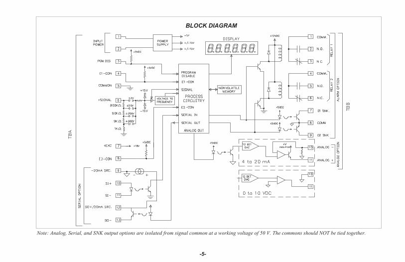
Note: Analog, Serial, and SNK output options are isolated from signal common at a working voltage of 50 V. The commons should NOT be tied together.
BLOCK DIAGRAM

PROGRAMMING AND OPERATING THE IMD1
PROGRAMMING THE IMD1
Prior to installing and operating the indicator, it may be necessary to changethe scaling to suit the display units particular to the application. (The unit isscaled from the factory to indicate directly in voltage, i.e. 2 V, 20 V, etc.,depending on the input range selected.) Although the unit has beenprogrammed at the factory, the set-ups will generally have to be changed.
The indicator is unique in that two different scaling methods are available. Theoperator may choose the method that yields the easier and more accuratecalibration for his application. The two scaling procedures are similar in that theoperator keys-in two display values and either keys-in or applies a signal valuethat corresponds to those display points (see figure below). The location of thescaling points should be near the process end limits, for the best possibleaccuracy. Once these values are programmed (coordinates on a graph), theindicator calculates the slope and intercept of the signal/display graphautomatically. No span/zero interaction occurs, making scaling a one-passexercise. Basic scaling is complete after decimal point selection, unit rounding(dummy zeros) and digital filtering level selection. The following graph shows atypical scale for the indicator.
The unit is shipped from the factory with only two scaling pointsprogrammed. Scaling point #1 is set to indicate 0.0 on the input display with0.0 VDC applied and scaling point #2 will indicate 2000.0 with a positive fullscale input voltage (ex. ±2 VDC) for each input range, except for the ±300VDC input range. The chart shows the display readings for full scale input anda 1 VDC input, if the factory settings are used for each range:
Display Reading Display ReadingVoltage Resolution For Full For 1 VDCRange Scale Input Input
±2 VDC 0.1 mVDC 2000.0 1000.0±20 VDC 1 mVDC 2000.0 100.0
±200 VDC 10 mVDC 2000.0 10.0±300 VDC 100 mVDC 300.0 1.0
Before programming the unit, it is advised to know the display reading forthe desired input and organize all data for the programming steps to avoid anyconfusion when programming the unit.
To set-up the indicator, first select the desired decade range by placing thefactory supplied jumper into the correct position at the rear of the unit. This selectsthe desired input range of the four available (refer to “Selecting The Input Range”for input range selection). Connect AC power and signal wires as outlined in theconnections section (Appendix “A”). Remove the jumper wire (if installed) fromTBA #3 (PGM. DIS.), this will allow the operator to enter and modify all of theindicator’s parameters. Press the front panel button labeled “P”, momentarily.Briefly, the display will show “Pro” alternately flashing with “0”. This is theindicator’s programming mode. The programming mode is divided into sections,numbered 0-9, each of which can be individually accessed. The front panel “UP”and “DOWN” arrow buttons can be used to select one of these numbers and the“P” button used to enter the selected programming module. In all of theprogramming modules, “UP” and “DOWN” are used to either select from a listof choices or enter a value. The “P” button is used to save the new value andprogress to the next step within a module (Note: the new value takes effect when“P” is pressed). Upon completion of a module, the indicator returns to the “Pro”< > “0” stage. Pressing the “P” button at this point causes the unit to display“End” after which the unit returns to the normal display mode. The followingtable explains the basic function of each step.Note: < > This indicates that the display will alternate between the English
prompt and the actual data.
-6-
SLOPE DIAGRAM

DISPLAY RESULT OF “P” BUTTON
“Pro” < > “0” - Causes the indicator to return to normal display mode. Anychanges to set-up data are permanently stored in the E2PROM.
“Pro” < > “1” - Entry into this module allows the user to select the decimalpoint position, unit rounding and scaling by the method ofapplying the actual signal levels to the indicator thatcorrespond to the programmed display values. Use thismethod when the transducer (signal source) is connected tothe process and the process can be brought to known levels(ie. weight, flow, pressure, etc.). Alternately, a precisionsignal source may be substituted to simulate the transducer.A second method is available in Pro 2.
“Pro” < > “2” - Entry into this module allows the user to select the decimalpoint position and unit rounding, as in Pro 1, but the methodof scaling differs in that the user keys in signal levels insteadof applying signals to the indicator. Use this method whenthe signal transducer (signal source) is pre-calibrated withknown display values at known signal levels. An alternatemethod is available in Pro 1.
“Pro” < > “3” - Module #3 allows the user to program what can be accessedfrom the front panel when the PGM. DIS. (TBA #3) pin isconnected to common. This feature protects critical set-updata from accidental modification while allowing access tosetpoints and other functions. The front panel lock-out menu(Quick programming) includes setpoint modification,totalizer resetting, and peak/valley resetting.Note: The term “Quick Programming” is used to refer to theability to change the information that can be accessed fromthe front panel when the “PGM. DIS.” terminal is connectedto “COMM.”.
DISPLAY RESULT OF “P” BUTTON
“Pro” < > “4” - Module #4 programs the digital filtering level and the functionof the remote input “E1-CON” pin (TBA #4), and, if thetotalizer option is installed, the remote input “E2-CON” pin(TBA #8). The functions of the remote E1 and E2 pins are thesame and include display hold, peak/valley modes, totalizerreset, alarm reset, signal re-zero (tare) , readingsynchronization or print request.
“Pro” < > “5” - This module sets the time base, scale factor and low signaldisable function for the optional totalizer/integrator.
“Pro” < > “6” - This module allows programming for the basic configurationof the alarm option. The programming includes HI/LOacting, tracking, alarm display, latched or auto-reset,assignment to either signal or integrator/totalizer, and alarmand hysteresis values.
“Pro” < > “7” - Module #7 is the serial communication parameter programming.Baud rate, unit address, print request function and condensedprints are all programmable.
“Pro” < > “8” - This module allows digital scaling of the retransmitted analogoutput. Display values that correspond to 4 mA or 0 VDC and20 mA or 10 VDC are keyed-in to scale the output and it maybe assigned to either the signal or the totalizer/integrator.
“Pro” < > “9” - This module is the service operations sequence and is notnormally accessed by the user. This step re-calibrates thebasic input and is used to compensate for long-term drift.Execution of this module should be done by technicians withthe proper equipment in accordance with a maintenance planof yearly recalibrations. A code number entry step is used toprotect from inadvertent entries. Also, there is a number ofother access codes which provide test and set-up changes asan aid in troubleshooting.
-7-
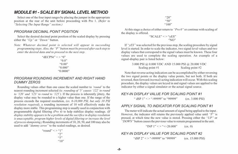
MODULE #1 - SCALE BY SIGNAL LEVEL METHODSelect one of the four input ranges by placing the jumper in the appropriate
position at the rear of the unit before proceeding with Pro 1. (Refer to“Selecting The Input Range” section.)
PROGRAM DECIMAL POINT POSITION
Select the desired decimal point position of the scaled display by pressingeither the “Up” or “Down” button.
Note: Whatever decimal point is selected will appear in succeedingprogramming steps. Also, the “P” button must be pressed after each step toenter the desired data and to proceed to the next step.
“dECPNt” < > “0”“0.0”
“0.00”“0.000”
“0.0000”
PROGRAM ROUNDING INCREMENT AND RIGHT HANDDUMMY ZEROS
Rounding values other than one cause the scaled number to ‘round’ to thenearest rounding increment selected (ie. rounding of ‘5’ causes ‘122’ to roundto ‘120’ and ‘123’ to round to ‘125’). If the process is inherently jittery, thedisplay value may be rounded to a higher value than one. If the range of theprocess exceeds the required resolution, (ex. 0-10,000 PSI, but only 10 PSIresolution required), a rounding increment of 10 will effectively make thedisplay more stable. This programming step is usually used in conjunction withprogrammable digital filtering (Pro 4) to help stabilize display readings. (Ifdisplay stability appears to be a problem and the sacrifice in display resolutionis unacceptable, program higher levels of digital filtering or increase the levelof process dampening.) Rounding increments of 10, 20, 50, and 100 may also beused to add “dummy zeros” to the scaled readings, as desired.
“round” < > “1”“2”“5”“10”
“20”“50”
“100”
At this stage a choice of either return to “Pro 0” or continue with scaling ofthe display is offered.
“SCALE” < > “yES”“NO”
If “yES” was selected for the previous step, the scaling procedure by signallevel is started. In order to scale the indicator, two signal level values and twodisplay values that correspond to the signal values must be known. These fourvalues are used to complete the scaling operation. An example of asignal-display pair is listed below:
3.000 PSI @ 0.000 VDC AND 15.000 PSI @ 20.000 VDCScaling point #1 Scaling point #2
Note that reverse acting indication can be accomplished by either reversingthe two signal points or the display value points, but not both. If both arereversed, then forward (normal) acting indication will occur. With this scalingprocedure, the display values are keyed in and signal values are applied to theindicator by either a signal simulator or the actual signal source.
KEY-IN DISPLAY VALUE FOR SCALING POINT #1
“ dSP 1” < > “-99999” to “99999” (ex. 3.000 PSI)
APPLY SIGNAL TO INDICATOR FOR SCALING POINT #1
The meter will indicate the actual amount of signal being applied to the input .However, the indicator still retains the previously applied value until “P” ispressed, at which time the new value is stored. Pressing either the “UP” or“DOWN” button causes the previous value to remain programmed in the unit.
“INP 1” < > “+/-20.000” (ex. 0)
KEY-IN DISPLAY VALUE FOR SCALING POINT #2
“dSP 2” < > “-99999” to “99999” (ex. 15.000 PSI)
-8-

APPLY SIGNAL TO INDICATOR FOR SCALING POINT #2
The meter will indicate the actual amount of signal being applied to the input.However, the indicator still retains the previous value until “P” is pressed, atwhich time the current value is stored. Pressing either the “UP” or “DOWN”button causes the previous value to remain programmed in the unit.
“INP 2” < > “+/-20000” (ex. 20000)
At this stage, scaling is complete. The indicator will automatically calculatethe slope and offset of the display units. After completing Pro 1, it isrecommended that the scaling operation be verified by applying varioussignals and checking the displayed reading.
If the totalizer/linearizer option is installed, the indicator, instead ofcompleting Module #1 and returning to “Pro 0”, will be ready to accept morescaling points for multisegment linearization. The quantity and location of thelinearization points should be chosen very carefully to best utilize the segmentsavailable. Refer to the section on linearization for a discussion on this matter.
PROGRAM NUMBER OF LINEAR SEGMENTS
This programming step loads in the number of linear segments desired formultisegment linearization. If just single slope scaling is all that is desired,input “1” for this step. If two segments are desired, input “2”, etc. You musthave one more scaling point known than the number of segments selected (ie.1 segment = 2 points, 2 segments = 3 points, etc). This step may be used tode-activate previously programmed segments where lower segments wouldoverride (ex. changing “SEGt” from 5 to 3 causes slopes 4&5 to be replacedby an extension of slope 3).
“SEGt” < > “1” - “9”
If “1” was selected, the indicator will return to “Pro 0” since scaling for thefirst segment was already completed. Otherwise, a choice of either returning to“Pro 0”or commencing with the multislope-linearization scaling is offered.
“SCALE” < > “yES”“NO”
KEY-IN DISPLAY VALUE FOR POINT #3
If “YES” was selected, the display value for the third point is entered.Otherwise, the indicator returns to “Pro 0”.
“dSP 3” < > “-99999” to “99999”
APPLY SIGNAL TO INDICATOR FOR POINT #3
The signal level value for point 3 is applied.
“INP 3” < > “+/-20000”
The sequence of entering display and signal values continues with “dSP 4”,“INP 4”, “dSP 5”, etc. until the number programmed for “SEGt” is reached.Upon completion, the indicator is scaled to the multiple segments. It isrecommended that the scaling be checked by applying signal values andverifying for correct display values.
Note: As the “UP” or “DOWN” button is continually held in, the display willprogressively increment faster until the fourth most significant digit ischanging at a rate of 1 number per second.
-9-
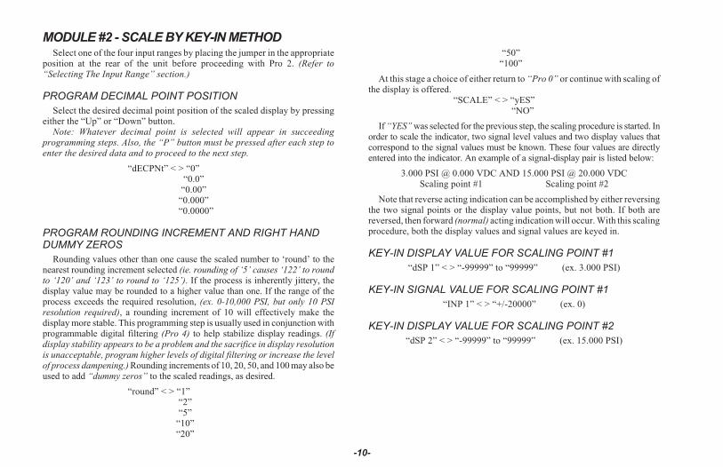
MODULE #2 - SCALE BY KEY-IN METHODSelect one of the four input ranges by placing the jumper in the appropriate
position at the rear of the unit before proceeding with Pro 2. (Refer to“Selecting The Input Range” section.)
PROGRAM DECIMAL POINT POSITION
Select the desired decimal point position of the scaled display by pressingeither the “Up” or “Down” button.
Note: Whatever decimal point is selected will appear in succeedingprogramming steps. Also, the “P” button must be pressed after each step toenter the desired data and to proceed to the next step.
“dECPNt” < > “0”“0.0”
“0.00”“0.000”“0.0000”
PROGRAM ROUNDING INCREMENT AND RIGHT HANDDUMMY ZEROS
Rounding values other than one cause the scaled number to ‘round’ to thenearest rounding increment selected (ie. rounding of ‘5’ causes ‘122’ to roundto ‘120’ and ‘123’ to round to ‘125’). If the process is inherently jittery, thedisplay value may be rounded to a higher value than one. If the range of theprocess exceeds the required resolution, (ex. 0-10,000 PSI, but only 10 PSIresolution required), a rounding increment of 10 will effectively make thedisplay more stable. This programming step is usually used in conjunction withprogrammable digital filtering (Pro 4) to help stabilize display readings. (Ifdisplay stability appears to be a problem and the sacrifice in display resolutionis unacceptable, program higher levels of digital filtering or increase the levelof process dampening.) Rounding increments of 10, 20, 50, and 100 may also beused to add “dummy zeros” to the scaled readings, as desired.
“round” < > “1”“2”“5”
“10”“20”
“50”“100”
At this stage a choice of either return to “Pro 0” or continue with scaling ofthe display is offered.
“SCALE” < > “yES”“NO”
If “YES” was selected for the previous step, the scaling procedure is started. Inorder to scale the indicator, two signal level values and two display values thatcorrespond to the signal values must be known. These four values are directlyentered into the indicator. An example of a signal-display pair is listed below:
3.000 PSI @ 0.000 VDC AND 15.000 PSI @ 20.000 VDCScaling point #1 Scaling point #2
Note that reverse acting indication can be accomplished by either reversingthe two signal points or the display value points, but not both. If both arereversed, then forward (normal) acting indication will occur. With this scalingprocedure, both the display values and signal values are keyed in.
KEY-IN DISPLAY VALUE FOR SCALING POINT #1
“dSP 1” < > “-99999” to “99999” (ex. 3.000 PSI)
KEY-IN SIGNAL VALUE FOR SCALING POINT #1
“INP 1” < > “+/-20000” (ex. 0)
KEY-IN DISPLAY VALUE FOR SCALING POINT #2
“dSP 2” < > “-99999” to “99999” (ex. 15.000 PSI)
-10-

KEY-IN SIGNAL VALUE FOR SCALING POINT #2
“INP 2” < > “+/-20000” (ex. 20000)
At this point, scaling is complete. The indicator will automatically calculatethe slope and offset of the display units. After completing Pro 2, it isrecommended that the scaling operation be verified by applying varioussignals and checking the displayed reading.
If the totalizer/linearizer option is installed, the indicator, instead of completingmodule #1 and returning to “Pro 0”, will be ready to accept more scaling pointsfor multisegment linearization. The quantity and location of the linearizationpoints should be chosen very carefully to best utilize the segments available.
Refer to the section on linearization for a discussion on this matter.
PROGRAM NUMBER OF LINEAR SEGMENTS
This programming step loads in the number of linear segments desired formultisegment linearization. If just single slope scaling is all that is desired,program “1” for this step. If two segments are desired, program “2”, etc. Youmust have one more scaling point known than the number of segmentsselected (ie. 1 segment = 2 points, 2 segments = 3 points, etc). This step mayalso be used to de-activate previously programmed segments where lowersegments would override (ex. changing “SEGt” from 5 to 3 causes slopes 4and 5 to be replaced by an extension of slope 3).
“SEGt” < > “1” - “9”
If “1” was selected, the indicator will return to “Pro 0” since scaling for thefirst slope was already completed. Otherwise, a choice of either returning to“Pro 0” or commencing with the multislope-linearization scaling is offered.
“SCALE” < > “yES”“NO”
If “yes” was selected, the display value for the third point is entered.Otherwise, the indicator returns to “Pro 0”.
KEY-IN DISPLAY VALUE FOR SCALING POINT #3
“dSP 3” < > “-99999” to “99999”
KEY-IN INPUT VALUE FOR SCALING POINT #3
“INP 3” < > “+/-20.000”
The sequence of entering display and signal values continues with “dSP 4”,“INP 4”, “dSP 5”, etc. until the number programmed for “SEGt” is reached.Upon completion, the indicator is scaled to the multiple segments. It isrecommended that the scaling be checked by exiting the programming modeand applying signal values and verifying for correct display values.
Note: As the “UP” or “DOWN” button is continually held in, the display willprogressively increment faster until the fourth most significant digit ischanging at a rate of 1 number per second.
-11-
MODULE #3 - PROGRAM FUNCTIONS ACCESSIBLE WITH FRONT PANEL LOCKOUTThis programming module programs what is accessible through the front
panel when the PGM. DIS. pin is connected to common (COMM.).
Note: The term “Quick Programming” is used to refer to the ability to changethe information that can be accessed from the front panel when the “PGM.DIS.” terminal is connected to “COMM.”.
DISPLAY ALARM VALUES
If the alarm option is installed, this selects whether the alarm values will orwill not be displayed.
“dSP AL” < > “yES” or “NO”
ENTER ALARM VALUES �
If “YES” was selected for display alarm values, this will select if alarm valuesmay be modified from the front panel. (If “NO” was selected for display alarmvalues, then this step will default to “NO” and will not be displayed for selection.)
“ENt AL” < > “yES” or “NO”
� Note: This sequence may be locked-out due to other programmed sequences.

DISPLAY HYSTERESIS VALUES
If the alarm option is installed, this selects whether the hysteresis valueswill or will not be displayed.
“dSPHYS” < > “yES” or “NO”
ENTER HYSTERESIS VALUES �
If “YES” was selected for display hysteresis values, this selects whetherhysteresis values may be modified from the front panel. (If “NO” was selectedfor display hysteresis values, then this step will default to “NO” and will notbe displayed for selection.)
“ENtHYS” < > “yES” or “NO”
RESET LATCHED ALARMS
If the alarm option is installed and if either alarm is programmed to latch,this will select if a latched alarm(s) can be reset from the front panel.
“rSt AL” < > “yES” or “NO”
DISPLAY PEAK/VALLEY MEMORY BUFFER
If the totalizer/linearizer option is installed, this selects whether peak andvalley buffers will be displayed.
“dSPbUF” < > “yES” or “NO”
RESET PEAK/VALLEY MEMORY BUFFER �
If “YES” was selected for the previous step, this selects whether the peakand valley buffers may be reset from the front panel. (If “NO” was selected,then this step defaults to “NO” and will not be displayed for selection.)
“rStbUF” < > “yES” or “NO”
SELECT DISPLAY *
If the totalizer/linearizer option is installed, this selects whether the displaycan be switched from input display to total display and from total display toinput display.
Note: When “NO” is selected, whatever display (Input or total) is shown, willbe the only display accessible.
“SELdSP” < > “yES” or “NO”
RESET TOTAL *
If the totalizer/linearizer option is installed, this selects whether the totalcan be reset from the front panel.
“rSttOt” < > “yES” or “NO”
RE-ZERO INPUT *
If the totalizer/linearizer option is installed, this selects whether the signalcan be re-zeroed (tared) through the front panel.
“tArE” < > “yES” or “NO”
Note: The tare buffer can be cleared by “stepping” through either “Pro 1” or“Pro 2”, using the P button or via serial communications.
Depending on functions selected under Pro 3 and Pro 6, alarms,hysteresis, peak, and valley values can be monitored and/or changed whenPGM. DIS. is tied to COMM. This provides a “QUICK PROGRAMMING”method for “day to day” process changes. (See QUICK PROGRAMMINGSECTION for more details.)
� Note: This sequence may be locked-out due to other programmed sequences.
* This function operates independent of the state of the “PGM. DIS.” pin.
-12-
MODULE #4 - PROGRAM DIGITAL FILTER AND REMOTE INPUT
PROGRAM DIGITAL FILTERING
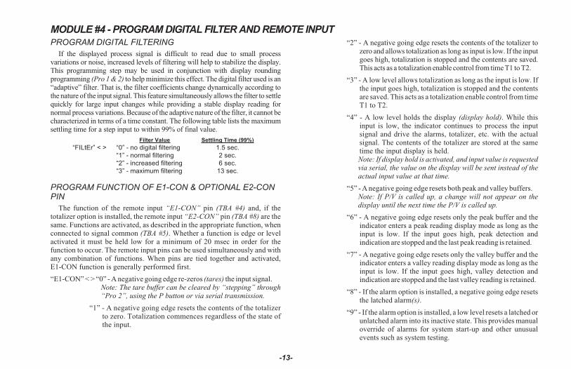
If the displayed process signal is difficult to read due to small processvariations or noise, increased levels of filtering will help to stabilize the display.This programming step may be used in conjunction with display roundingprogramming (Pro 1 & 2) to help minimize this effect. The digital filter used is an“adaptive” filter. That is, the filter coefficients change dynamically according tothe nature of the input signal. This feature simultaneously allows the filter to settlequickly for large input changes while providing a stable display reading fornormal process variations. Because of the adaptive nature of the filter, it cannot becharacterized in terms of a time constant. The following table lists the maximumsettling time for a step input to within 99% of final value.
Filter Value Settling Time (99%)
“FILtEr” < > “0” - no digital filtering 1.5 sec.
“1” - normal filtering 2 sec.
“2” - increased filtering 6 sec.
“3” - maximum filtering 13 sec.
PROGRAM FUNCTION OF E1-CON & OPTIONAL E2-CONPIN
The function of the remote input “E1-CON” pin (TBA #4) and, if thetotalizer option is installed, the remote input “E2-CON” pin (TBA #8) are thesame. Functions are activated, as described in the appropriate function, whenconnected to signal common (TBA #5). Whether a function is edge or levelactivated it must be held low for a minimum of 20 msec in order for thefunction to occur. The remote input pins can be used simultaneously and withany combination of functions. When pins are tied together and activated,E1-CON function is generally performed first.
“E1-CON” < > “0” - A negative going edge re-zeros (tares) the input signal.Note: The tare buffer can be cleared by “stepping” through“Pro 2”, using the P button or via serial transmission.
“1” - A negative going edge resets the contents of the totalizerto zero. Totalization commences regardless of the state ofthe input.
“2” - A negative going edge resets the contents of the totalizer tozero and allows totalization as long as input is low. If the inputgoes high, totalization is stopped and the contents are saved.This acts as a totalization enable control from time T1 to T2.
“3” - A low level allows totalization as long as the input is low. Ifthe input goes high, totalization is stopped and the contentsare saved. This acts as a totalization enable control from timeT1 to T2.
“4” - A low level holds the display (display hold). While thisinput is low, the indicator continues to process the inputsignal and drive the alarms, totalizer, etc. with the actualsignal. The contents of the totalizer are stored at the sametime the input display is held.Note: If display hold is activated, and input value is requestedvia serial, the value on the display will be sent instead of theactual input value at that time.
“5” - A negative going edge resets both peak and valley buffers.Note: If P/V is called up, a change will not appear on thedisplay until the next time the P/V is called up.
“6” - A negative going edge resets only the peak buffer and theindicator enters a peak reading display mode as long as theinput is low. If the input goes high, peak detection andindication are stopped and the last peak reading is retained.
“7” - A negative going edge resets only the valley buffer and theindicator enters a valley reading display mode as long as theinput is low. If the input goes high, valley detection andindication are stopped and the last valley reading is retained.
“8” - If the alarm option is installed, a negative going edge resetsthe latched alarm(s).
“9” - If the alarm option is installed, a low level resets a latched orunlatched alarm into its inactive state. This provides manualoverride of alarms for system start-up and other unusualevents such as system testing.
-13-

“10” - A negative going edge toggles the display between“input” and “total” (from input to total, or vice versa). Noaction is taken on the positive going edge.
“11” - A negative going edge zeros (tares) the input signal andadds the value that was in the input display to the totalizervalue, every time this operation is performed. Thetime-base, scale factor and low cut-out in “Module #5” arein affect disabled, when this function is selected.
“12”- Display hold with tare. A negative going edge tares (zeros)the input signal. Prior to the tare operation, the input signal issaved and held (display hold) as long as the remote input pinis low. On the positive edge, the input display will showzero. If there is an increase to the input signal while theremote input is low, the display will reflect (show) theincrease at the positive edge.
“13”- Instrument reading synchronization. A low level disablesall meter operations (alarms, total, analog out, etc.). Apositive edge resets the start of the A/D conversion, to allowsynchronization with external processes and controls. Whilein this function, the other E-CON pin will be operational.
“14”- Print request. Transmits data according to the print optionsthat have been selected in Program Module #7. If the lowtime exceeds 800 msec, a second print-out may occur.
“E2-CON” < > If the totalizer option is installed, E2-CON has the sameprogrammable functions as E1-CON.
-14-
MODULE #5 - PROGRAM INTEGRATOR/TOTALIZERProgramming for the integrator/totalizer consists of four programming steps:
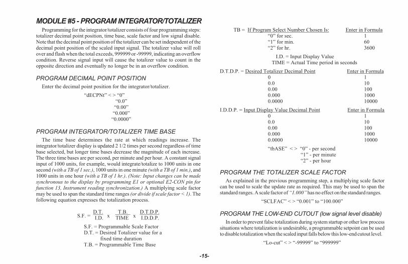
totalizer decimal point position, time base, scale factor and low signal disable.Note that the decimal point position of the totalizer can be set independent of thedecimal point position of the scaled input signal. The totalizer value will rollover and flash when the total exceeds, 999999 or -99999, indicating an overflowcondition. Reverse signal input will cause the totalizer value to count in theopposite direction and eventually no longer be in an overflow condition.
PROGRAM DECIMAL POINT POSITION
Enter the decimal point position for the integrator/totalizer.
“dECPNt” < > “0”“0.0”
“0.00”“0.000”
“0.0000”
PROGRAM INTEGRATOR/TOTALIZER TIME BASE
The time base determines the rate at which readings increase. Theintegrator/totalizer display is updated 2 1/2 times per second regardless of timebase selected, but longer time bases decrease the magnitude of each increase.The three time bases are per second, per minute and per hour. A constant signalinput of 1000 units, for example, would integrate/totalize to 1000 units in onesecond (with a TB of 1 sec.), 1000 units in one minute (with a TB of 1 min.), and1000 units in one hour (with a TB of 1 hr.). (Note: Input changes can be madesynchronous to the display by programming E1 or optional E2-CON pin forfunction 13, Instrument reading synchronization.) A multiplying scale factormay be used to span the standard time ranges (or divide if scale factor < 1). Thefollowing equation expresses the totalization process.
S.F. =D.T.
xT.B.
xD.T.D.P.
I.D. TIME I.D.D.P.
S.F. = Programmable Scale FactorD.T. = Desired Totalizer value for a
fixed time durationT.B. = Programmable Time Base
TB = If Program Select Number Chosen Is: Enter in Formula“0” for sec. 1“1” for min. 60“2” for hr. 3600
I.D. = Input Display ValueTIME = Actual Time period in seconds
D.T.D.P. = Desired Totalizer Decimal Point Enter in Formula0 10.0 100.00 1000.000 10000.0000 10000
I.D.D.P. = Input Display Value Decimal Point Enter in Formula0 10.0 100.00 1000.000 10000.0000 10000
“tbASE” < > “0” - per second“1” - per minute“2” - per hour
PROGRAM THE TOTALIZER SCALE FACTOR
As explained in the previous programming step, a multiplying scale factorcan be used to scale the update rate as required. This may be used to span thestandard ranges. A scale factor of “1.000” has no effect on the standard ranges.
“SCLFAC” < > “0.001” to “100.000”
PROGRAM THE LOW-END CUTOUT (low signal level disable)
In order to prevent false totalization during system startup or other low processsituations where totalization is undesirable, a programmable setpoint can be usedto disable totalization when the scaled input falls below this low-end cutout level.
“Lo-cut” < > “-99999” to “999999”
-15-
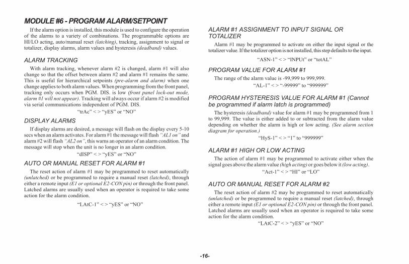
MODULE #6 - PROGRAM ALARM/SETPOINTIf the alarm option is installed, this module is used to configure the operation
of the alarms to a variety of combinations. The programmable options areHI/LO acting, auto/manual reset (latching), tracking, assignment to signal ortotalizer, display alarms, alarm values and hysteresis (deadband) values.
ALARM TRACKING
With alarm tracking, whenever alarm #2 is changed, alarm #1 will alsochange so that the offset between alarm #2 and alarm #1 remains the same.This is useful for hierarchical setpoints (pre-alarm and alarm) when onechange applies to both alarm values. When programming from the front panel,tracking only occurs when PGM. DIS. is low (front panel lock-out mode,alarm #1 will not appear). Tracking will always occur if alarm #2 is modifiedvia serial communications independent of PGM. DIS.
“trAc” < > “yES” or “NO”
DISPLAY ALARMS
If display alarms are desired, a message will flash on the display every 5-10secs when an alarm activates. For alarm #1 the message will flash “AL1 on” andalarm #2 will flash “AL2 on”, this warns an operator of an alarm condition. Themessage will stop when the unit is no longer in an alarm condition.
“dISP” < > “yES” or “NO”
AUTO OR MANUAL RESET FOR ALARM #1
The reset action of alarm #1 may be programmed to reset automatically(unlatched) or be programmed to require a manual reset (latched), througheither a remote input (E1 or optional E2-CON pin) or through the front panel.Latched alarms are usually used when an operator is required to take someaction for the alarm condition.
“LAtC-1” < > “yES” or “NO”
ALARM #1 ASSIGNMENT TO INPUT SIGNAL ORTOTALIZER
Alarm #1 may be programmed to activate on either the input signal or thetotalizer value. If the totalizer option is not installed, this step defaults to the input.
“ASN-1” < > “INPUt” or “totAL”
PROGRAM VALUE FOR ALARM #1
The range of the alarm value is -99,999 to 999,999.
“AL-1” < > “-99999” to “999999”
PROGRAM HYSTERESIS VALUE FOR ALARM #1 (Cannotbe programmed if alarm latch is programmed)
The hysteresis (deadband) value for alarm #1 may be programmed from 1to 99,999. The value is either added to or subtracted from the alarm valuedepending on whether the alarm is high or low acting. (See alarm sectiondiagram for operation.)
“HyS-1” < > “1” to “999999”
ALARM #1 HIGH OR LOW ACTING
The action of alarm #1 may be programmed to activate either when thesignal goes above the alarm value (high acting) or goes below it (low acting).
“Act-1” < > “HI” or “LO”
AUTO OR MANUAL RESET FOR ALARM #2
The reset action of alarm #2 may be programmed to reset automatically(unlatched) or be programmed to require a manual reset (latched), througheither a remote input (E1 or optional E2-CON pin) or through the front panel.Latched alarms are usually used when an operator is required to take someaction for the alarm condition.
“LAtC-2” < > “yES” or “NO”
-16-
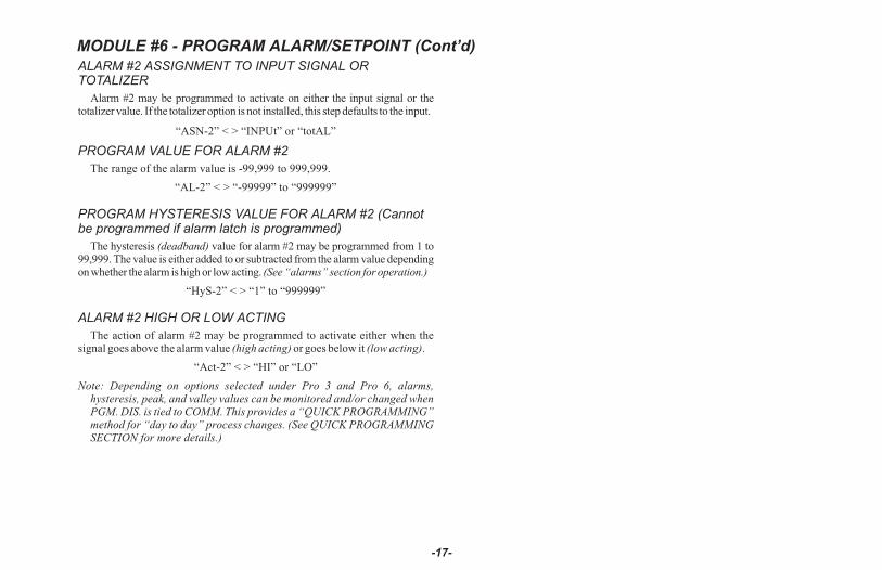
ALARM #2 ASSIGNMENT TO INPUT SIGNAL ORTOTALIZER
Alarm #2 may be programmed to activate on either the input signal or thetotalizer value. If the totalizer option is not installed, this step defaults to the input.
“ASN-2” < > “INPUt” or “totAL”
PROGRAM VALUE FOR ALARM #2
The range of the alarm value is -99,999 to 999,999.
“AL-2” < > “-99999” to “999999”
PROGRAM HYSTERESIS VALUE FOR ALARM #2 (Cannotbe programmed if alarm latch is programmed)
The hysteresis (deadband) value for alarm #2 may be programmed from 1 to99,999. The value is either added to or subtracted from the alarm value dependingon whether the alarm is high or low acting. (See “alarms” section for operation.)
“HyS-2” < > “1” to “999999”
ALARM #2 HIGH OR LOW ACTING
The action of alarm #2 may be programmed to activate either when thesignal goes above the alarm value (high acting) or goes below it (low acting).
“Act-2” < > “HI” or “LO”
Note: Depending on options selected under Pro 3 and Pro 6, alarms,hysteresis, peak, and valley values can be monitored and/or changed whenPGM. DIS. is tied to COMM. This provides a “QUICK PROGRAMMING”method for “day to day” process changes. (See QUICK PROGRAMMINGSECTION for more details.)
-17-
MODULE #6 - PROGRAM ALARM/SETPOINT (Cont’d)

MODULE #7 - PROGRAM SERIAL COMMUNICATIONSSeveral programmable parameters must be programmed before serial
communication can occur.
BAUD RATE
Select one of the baud rates from the list to match the baud rate of theprinter, computer, controller, etc.
“bAud” < > “300” - 300 baud“600” - 600 baud“1200” - 1200 baud“2400” - 2400 baud
UNIT ADDRESS NUMBER
To allow multiple units to communicate on the 20 mA loop, different addressnumbers must be assigned to each unit. If only one unit is on the loop, an addressof “0” may be given, eliminating the need for the address command.
“AddrES” < > “0” to “99”
PRINT REQUEST FUNCTION
A selection of print operations can be programmed. A print operationoccurs when a print request is activated via E1-CON (TBA #4) or optionalE2-CON (TBA #8) pin, or a “P” command is sent from a terminal via the serialcommunications option. If the option to which a particular print code appliesis not installed, then that parameter will not be printed.
If the totalizer is overflowed, an asterisk (*) will precede the digits that areprinted (ex. *000127 positive overflow, -*00127 negative overflow). If the inputis overloaded, the print-out will be “OLOLOL” and for underload “ULULUL”.
“Print” < > “0” - input signal“1” - input signal, peak, valley and tare“2” - input signal, alarm 1, and alarm 2“3” - input signal, alarm 1, alarm 2,
hysteresis 1, hysteresis 2, peak, valley, and tare“4” - totalizer“5” - input signal and totalizer“6” - input signal, totalizer, peak, valley, and tare
“7” - totalizer, alarm 1, and alarm 2“8” - input signal, totalizer, alarm 1, and alarm 2“9” - input signal, totalizer, alarm 1, alarm 2,
hysteresis 1, hysteresis 2, peak, valley, and tare
FULL OR ABBREVIATED TRANSMISSION
When transmitting data, the IMD1 can be programmed to suppress theaddress number, mnemonics and some spaces, if desired, by selecting “NO”.A selection of “NO” results in faster transmission. This feature may be helpfulwhen interfacing with a computer. When interfacing to a printer, a “yES”response is usually desirable.
“FULL” < > “yES” or “NO”
An example of full and abbreviated transmission is shown below:
2 INP -125.75 < CR > < LF > Full transmission-125.75 < CR > < LF > Abbreviated transmission
-18-
MODULE #8 - PROGRAM RE-TRANSMITTED ANALOG OUTPUTThis programming module allows digital scaling of the 4 to 20 mA or 0 to
10 VDC analog output. The type of analog output is determined by the modelordered. (See Ordering Information for available models.) The display valueat which 4 mA or 0 VDC and the display value at which 20 mA or 10 VDC aretransmitted are keyed-in. The indicator automatically calculates slope andintercept values to complete the scaling. The analog output then follows thecalculated display value and as such will update every measurement cycle.The output may also be programmed to proportionally retransmit the contentsof the totalizer instead of the input. Reverse acting output can be achieved byprogramming the “high” display value for the “AN-LO” programming stepand the “low” display value for the “AN-HI” step.
Note: DO NOT ADJUST THE ANALOG OUTPUT POTS ON THE BACK OFTHE UNIT. Fine offset and span adjustment pots are externally accessibleto compensate for small drifts in the output. These pots have been set at thefactory and do not normally require adjustment.
ANALOG OUTPUT SOURCE
Program whether the input signal or the totalizer will serve as the basis forthe analog output signal. If the totalizer/linearizer option is not installed, thenthis step defaults to “Input”.
“ASIN” < > “INPUt” or “totAL”
ANALOG OUTPUT LO DISPLAY VALUE
Program the display value at which the analog output transmits 4 mA or0 VDC.
“AN-Lo” < > “-99999” to “999999”
ANALOG OUTPUT HI DISPLAY VALUE
Program the display value at which the analog output transmits 20 mA or10 VDC.
“AN-HI” < > “-99999” to “999999”
-19-
MODULE #9 - SERVICE OPERATIONSThe indicator has been fully calibrated at the factory and will only require a
scaling operation (Pro 1 or 2) to display the units of the process. If the unitappears to be indicating incorrectly or inaccurately, refer to thetroubleshooting section before attempting this procedure.
When re-calibration is required (generally every 2 years), this procedureshould only be performed by qualified technicians using appropriateequipment. Signal source accuracies of 0.01% or better are required.
The procedure consists of applying accurate signal levels to the indicatorin a series of three steps. Allow a 30 minute warm-up period before startingthis procedure.
Note: Once the access Code 48 has been entered, there is no exiting thisprogram module without completing the calibration procedure.
ENTER ACCESS CODE
A code number (48) must be keyed-in prior to the calibration sequence toguard against inadvertent entries. Access code numbers other then those listedin this section, should not be entered at this step. If any are entered, undefinedor unpredictable operation could result.
“CodE” < > “0” to “99”
If the code number for the previous step was not recognized, the indicatorreturns to “Pro 0”, with no action taken. Otherwise, the calibrationprocedure is started.
SELECT SCALE REQUIRED
Place the factory supplied jumper in one of the four positions to select an inputrange. (Refer to “Selecting The Input Range” section for more information.)
ENTER (-)100% OF PROCESS
Apply (-) full scale of the range which was selected. Allow the signal tostabilize for 20 seconds before pressing “P”.
“StEP 1” (Press “P”)
ENTER ZERO REFERENCE
Apply 0 volts by shorting the inputs together.
“StEP 2” (Press “P”)
ENTER (+)100% OF PROCESS
Apply (+) full scale of the range which was selected. Allow the signal tostabilize for 20 seconds before pressing “P”.
“StEP 3” (Press “P”)
Indicator calibration is complete. It is recommended that calibration bechecked by entering “Pro 1” and checking the displayed input values with thesignal source at different applied input levels.
SERIAL HARDWARE (loop-back) DIAGNOSTICS
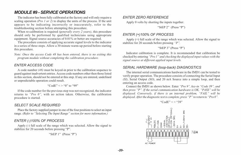
The internal serial communications hardware in the IMD1 can be tested toverify proper operation. The procedure consists of connecting the Serial Input(SI), Serial Output (SO), and 20 mA Source into a simple loop, and thenentering an access code.
Connect the IMD1 as shown below. Enter “Pro 9”, key-in “Code 39”, andthen press “P”. If the serial communication hardware is OK, “PASS” will bedisplayed. Conversely, if there is an internal problem, “FAIL” will bedisplayed. After the diagnostic test is complete, press “P” to return to “Pro 0”.
“CodE” < > “39”
-20-

MODULE #9 - SERVICE OPERATIONS (Cont’d)
RESTORING ALL PROGRAMMING PARAMETERS BACKTO FACTORY CONFIGURATION
All of the programming in Modules #1 through #8 can be restored back tothe factory configuration by entering a specific access code (refer to the“Factory Configuration” section for the data that will be entered). Theprocedure consists of entering “Pro 9”, keying-in “Code 66”, and thenpressing “P”. The IMD1 responds by displaying “INItAL” for severalseconds, and then returns to “Pro 0”.Note: When this procedure is performed, all of the scaling, presets, etc. that
were programmed into the IMD1 will be overwritten.
“CodE” < > “66”
OPERATING THE IMD1
After completing input range selection, scaling and all set-up operations,the unit is ready to install and operate. After power is applied, a display testconsisting of illuminating all segments for 2 seconds is performed. Afterward,the input or total will appear, depending upon the display mode prior to the lastpower-down. To switch the display to input, press “DOWN” (indicated by“arrows” on the front panel) and to switch it to total, press “UP”. If thetotalizer/linearizer option is not installed, then display switching to total isinoperative. A minus sign “-” will precede numbers that are negative. If adecimal point is chosen, one leading and one or more trailing zeros willaccompany the decimal point.
QUICK PROGRAMMING
To limit access to the set-up parameters, connect a key-switch or wire fromPGM. DIS. (TBA #3) to COMM. (TBA #5). With this pin connected tocommon, only a predetermined amount of data can be viewed or altered, asprogrammed by programming module #3. If “NO” was programmed for all ofthe available steps in module #3, then pressing “P” will cause the unit todisplay “Loc”. However, if “YES” was programmed in one or more of thesteps, then “P” will invoke entry into a series of commonly modifiedparameters while protecting the crucial set-up information. This is referred toas the “quick programming” mode. When “quick programming” mode isentered, the alarms and hysteresis values can be modified in the same manner
as in the regular programming mode. The new alarm and hysteresis values willtake effect when “P” is pressed. The other operations in the “quickprogramming” mode require special key sequences as shown:
To reset latched alarm, scroll through steps in “quickprogramming” mode using the “P” button until “LAtCH1” or“LAtCH2” appears in the display. If they do not appear, they arenot latched.
To reset: While “LAtCH1” or “LAtCH2” is beingdisplayed, press and hold “DOWN” and press“P”. Pressing “P” alone causes a step to the nextitem with no action taken on the alarm.
To reset peak and valley buffers, scroll through steps in “quickprogramming” mode using the “P” button until “PEA” or“VAL” appears in the display.
To reset: While “PEA” or “VAL” is beingdisplayed, press and hold “DOWN” and press“P”. Pressing “P” alone causes a step to the nextitem with no action taken on the buffer.
The front panel buttons are not only used to input data during theprogramming and “quick programming” mode, but control a number of otherfunctions (if enabled in Pro “3”) as well. In the normal meter mode, thesefunctions are available:
To Switch to display of input: Press “DOWN” button.To Switch to display of totalizer: Press “UP” button.To re-zero input (tare): Press and hold “DOWN” and press “P”.To reset totalizer to zero: Press and hold “UP” and press “P”.To Enter programming or “quick programming”: Press “P”.
After each operation, a message will appear briefly to acknowledge the action.
-21-
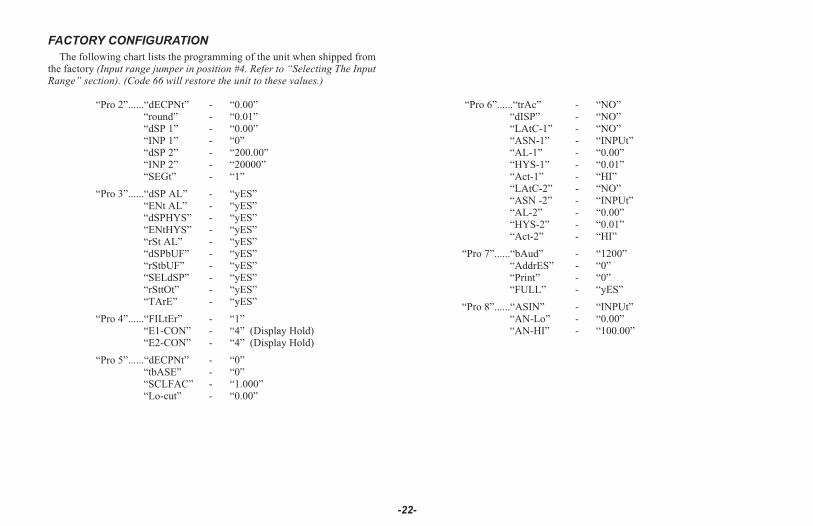
FACTORY CONFIGURATION
The following chart lists the programming of the unit when shipped fromthe factory (Input range jumper in position #4. Refer to “Selecting The InputRange” section). (Code 66 will restore the unit to these values.)
“Pro 2”......“dECPNt” - “0.00”“round” - “0.01”“dSP 1” - “0.00”“INP 1” - “0”“dSP 2” - “200.00”“INP 2” - “20000”“SEGt” - “1”
“Pro 3”......“dSP AL” - “yES”“ENt AL” - “yES”“dSPHYS” - “yES”“ENtHYS” - “yES”“rSt AL” - “yES”“dSPbUF” - “yES”“rStbUF” - “yES”“SELdSP” - “yES”“rSttOt” - “yES”“TArE” - “yES”
“Pro 4”......“FILtEr” - “1”“E1-CON” - “4” (Display Hold)“E2-CON” - “4” (Display Hold)
“Pro 5”......“dECPNt” - “0”“tbASE” - “0”“SCLFAC” - “1.000”“Lo-cut” - “0.00”
“Pro 6”......“trAc” - “NO”“dISP” - “NO”“LAtC-1” - “NO”“ASN-1” - “INPUt”“AL-1” - “0.00”“HYS-1” - “0.01”“Act-1” - “HI”“LAtC-2” - “NO”“ASN -2” - “INPUt”“AL-2” - “0.00”“HYS-2” - “0.01”“Act-2” - “HI”
“Pro 7”......“bAud” - “1200”“AddrES” - “0”“Print” - “0”“FULL” - “yES”
“Pro 8”......“ASIN” - “INPUt”“AN-Lo” - “0.00”“AN-HI” - “100.00”
-22-
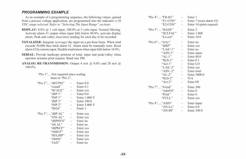
PROGRAMMING EXAMPLE
As an example of a programming sequence, the following values, gainedfrom a process voltage application, are programmed into the indicator (±20VDC range selected. Refer to “Selecting The Input Range” section).
DISPLAY: 0.0% @ 1 volt input, 100.0% at 5 volts input. Normal filtering.Activate alarm #1 output when input falls below 80.0%, activate displayalarm. Peak and valley (max/min) reading for each day to be recorded.
TOTALIZER: Integrate (average) the input on a per-hour basis. When totalexceeds 50,000 then latch alarm #2. Alarm must be manually reset. Resetalarm #2 by remote input. Disable totalization when input falls below 10.0%.
SERIAL: Provide hardcopy printout of total, input and peak/valley whenoperator actuates print request. Baud rate 300.
ANALOG RE-TRANSMISSION: Output 4 mA @ 0.0% and 20 mA @100.0%.
“Pro 1”.....Not required since scalingdone in “Pro 2”.
“Pro 2”.....“dECPNt” - Enter 0.0“round” - Enter 0.1“SCALE” - Enter yes“dSP 1” - Enter 0.0“INP 1” - Enter 1.000 V“dSP 2” - Enter 100.0“INP 2” - Enter 5.000 V“SEGt” - Enter 1
“Pro 3”.....“dSP AL” - Enter yes“ENt AL” - Enter yes“dSPHYS” - Enter no“rSt AL” - Enter no“dSPbUF” - Enter yes“rStbUF” - Enter yes“SELdSP” - Enter yes“rSttOt” - Enter yes“tArE” - Enter no
“Pro 4”.....“FILtEr” - Enter 1“E1-CON” - Enter 7 (reset alarm #2)“E2-CON” - Enter 14 (print request)
“Pro 5”.....“tbASE” - Enter 2“SCLFAC” - Enter 1.000“Lo-cut” - Enter 10.0
“Pro 6”.....“trAc” - Enter no“dISP” - Enter yes“LAtC-1” - Enter no“ASN-1” - Enter input“AL-1” - Enter 80.0“HyS-1” - Enter 0.1“Act-1” - Enter LO“LAtC-2” - Enter yes“ASN -2” - Enter total“AL-2” - Enter 5000.0“HyS-2” - N/A“Act-2” - Enter HI
“Pro 7”.....“bAud” - Enter 300“AdrrES” - Enter 0“Print” - Enter 6“FULL” - Enter yes
“Pro 8”.....“ASIN” - Enter input“AN-Lo” - Enter 0.0“AN-HI” - Enter 100.0
-23-

PNEUMATIC PRESSURE EXAMPLE
An IMD1 is employed to monitor and display the pneumatic (air) pressureof a robotic assembly system at a manufacturing plant. Several “dedicated”robotic arms are used to fasten bolts which join pieces of material together.The robotic arms will operate correctly, so long as the system pressureremains between 160.0 to 180.0 PSI. If the pressure were to drop below 160.0PSI, the bolts would not be properly fastened. If the pressure became greaterthan 180.0 PSI, then the bolts would be over tightened and the threads maystrip, or damage to the product may occur.
A 0-10 VDC (0-250.0 PSI) linearized pressure transducer is used and the±20 V range of the IMD is selected. The IMD is scaled to display 0 @ 0 VDCand 250.0 @ 10 VDC. Alarm #1 is programmed to activate a warning signalwhen the pressure exceeds 180.0 PSI. Alarm #2 is programmed to latch andactivate a warning bell and light if the pressure falls below 160.0 PSI. Thesoftware option is specified, to record daily high (peak) and low (valley)pressures to assist in isolating any pressure problems within the system.
Basic programming is as follows:
“Pro 1”.....“dECPNt” - Enter 0.0“round” - Enter 1“SCALE” - Enter yES“dSP 1” - Enter 0.0“INP 1” - Enter 0 (apply 0 VDC)“dSP 2” - Enter 250.0“INP 2” - Enter 10.000 (apply 10 VDC)“SEGt” - Enter 1 (single segment scaling)
“Pro 3”.....“dSP AL” - Enter yES“ENt AL” - Enter NO“dSPHYS” - Enter NO“rSt AL” - Enter yES“dSPbUF” - Enter yES“rStbUF” - Enter yES“SELdSP” - Enter yES“rSttOt” - Enter NO“tArE” - Enter NO
“Pro 6”.....“trAc” - Enter NO“dISP” - Enter yES
“LAtC-1” - Enter NO“ASN-1” - Enter input“AL-1” - Enter 180.0“HYS-1” - Enter 1“Act-1” - Enter HI“LAtC-2” - Enter yES“ASN -2” - Enter input“AL-2” - Enter 160.0“HYS-2” - N/A“Act-2” - Enter LO
-24-

-25-
EXCITATION (Optional)The optional regulated excitation voltage (18 VDC, 60 mA max.) can be
used to power the transducer. The common of the excitation voltage isinternally connected to “COMM” (TBA #5). The excitation voltage is NOT tobe used for powering relay coils, serial communication loops, etc., due to thesensitive nature of signal common.
TOTALIZER/LINEARIZER/PEAK/VALLEY/TARE(Optional)
TOTALIZER
The totalizer option simply totals (adds) input readings together using aprogrammable time base and scaling coefficient. The decimal point position ofthe totalizer can be programmed independent of the input signal. The totalizermay be reset through a remote input, by the front panel or through the serialcommunications option. Alarms may be programmed to trigger from totalizervalues; for example to total flow for batching operations. The programmable timebases are “per second”, “per minute” and “per hour”, meaning the totalizer willaccumulate at a fixed rate of 21
2 times per second and be equal to a fixed inputsignal level over the selected time period. For example, if the input signal is aconstant 1000 units and the “per minute” time base is selected, the totalizer willaccumulate at the rate of 1000 units per minute. The totalizer is updated at this rateevery 400 msec. As a result, the input signal is accumulated in “batches” of 6.6counts every 400 msec. Therefore, the totalizer start and stop sequencing, as wellas the alarm values set to trigger at specific totalizer values, are accurate only tothe 400 msec totalizer update rate. The preceding example requires a scale factorof 1.000 to yield exact time bases, but any scale factor can be used to span betweenthe ranges. (See section on totalizer programming for detailed information.) Aprogrammable low signal level disable feature completes the totalizer features(this will stop totalization when the signal level drops below this programmedvalue, “low cut”). At loss of power to the indicator, the contents of the totalizer aresaved. This will allow totalizing over consecutive shifts, days, etc. The total canaccumulate to 999,999. If the low-end cutout value is programmed negative (ex.-100, reference Program Module #5), and the input signal is between zero and thelow-end cutout value, the totalizer value will decrement. If the input signal goesabove zero the total will increment. If the signal goes below (more negative than),the low-end cutout value, totalization will stop.
Note: The totalizer value will roll over and flash when the total exceeds,999999 or -99999, indicating an overflow condition. Reverse signal inputwill cause the totalizer value to count in the opposite direction andeventually no longer be in an overflow condition.
TOTALIZER EXAMPLE
The indicator is employed to indicate and totalize the natural gas consumptionof a factory. A gas flow meter with a linearized 0-5 VDC output that corresponds to0 to 250 CFM is selected. The input is scaled to read the actual gas flow in cubicfeet per minute (CFM) with 0.01 CFM resolution and the totalizer is scaled toindicate total cubic feet used. The ±20 VDC range is selected. In order to hold anddisplay larger values, the totalizer is scaled to display the total gas usage (cu. ft.) inhundredths. The following programming steps are followed:
BASIC SET-UP“Pro 1 or 2”.....“dECPNt” - 0.00
“round” - 0.01“dSP 1” - 0.00“INP 1” - 0.000“dSP 2” - 250.00“INP 2” - 5.000
TOTALIZER SET-UPWith an average signal input which gives a Process Display of 250.00 CFM
for a one-minute time period, the following formula applies:
S.F. =D.T.
x ( T.B.) *x
D.T.D.P.I.D. TIME I.D.D.P.
S.F. = Programmable Scale FactorD.T. = Desired Totalizer value for a
fixed time durationT.B. = Programmable Time Base
T.B. = If Program Select Number Chosen Is: Enter in Formula“0” for sec. 1“1” for min. 60“2” for hr. 3600
I.D. = Input Display ValueTIME = Actual Time period in seconds
D.T.D.P. = Desired Totalizer Decimal Point Enter in Formula0 10.0 100.00 1000.000 10000.0000 10000
I.D.D.P. = Input Display Decimal Point Enter in Formula0 10.0 100.00 1000.000 10000.0000 10000
S.F . =250 cu. ft. (Hundreds)
x (60**) *x
1S.F.= 1x1x.01 S.F.=.01250 CFM 60 100
“Pro 5”.....“dECPNt” - 0“tbASE” - 1“SCLFAC” - 0.010“Lo-cut” - 0.00
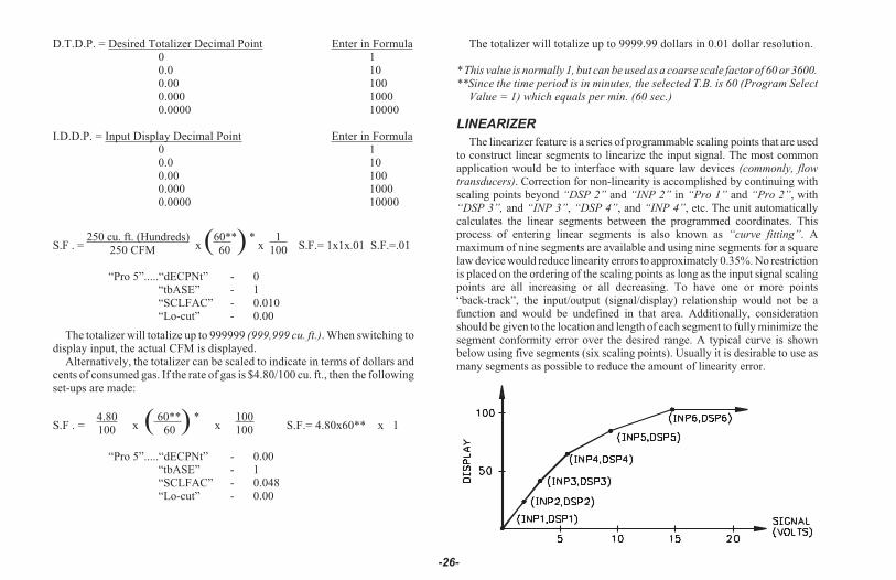
The totalizer will totalize up to 999999 (999,999 cu. ft.). When switching todisplay input, the actual CFM is displayed.
Alternatively, the totalizer can be scaled to indicate in terms of dollars andcents of consumed gas. If the rate of gas is $4.80/100 cu. ft., then the followingset-ups are made:
S.F . =4.80
x ( 60**) *x
100S.F.= 4.80x60** x 1100 60 100
“Pro 5”.....“dECPNt” - 0.00“tbASE” - 1“SCLFAC” - 0.048“Lo-cut” - 0.00
The totalizer will totalize up to 9999.99 dollars in 0.01 dollar resolution.
* This value is normally 1, but can be used as a coarse scale factor of 60 or 3600.**Since the time period is in minutes, the selected T.B. is 60 (Program Select
Value = 1) which equals per min. (60 sec.)
LINEARIZER
The linearizer feature is a series of programmable scaling points that are usedto construct linear segments to linearize the input signal. The most commonapplication would be to interface with square law devices (commonly, flowtransducers). Correction for non-linearity is accomplished by continuing withscaling points beyond “DSP 2” and “INP 2” in “Pro 1” and “Pro 2”, with“DSP 3”, and “INP 3”, “DSP 4”, and “INP 4”, etc. The unit automaticallycalculates the linear segments between the programmed coordinates. Thisprocess of entering linear segments is also known as “curve fitting”. Amaximum of nine segments are available and using nine segments for a squarelaw device would reduce linearity errors to approximately 0.35%. No restrictionis placed on the ordering of the scaling points as long as the input signal scalingpoints are all increasing or all decreasing. To have one or more points“back-track”, the input/output (signal/display) relationship would not be afunction and would be undefined in that area. Additionally, considerationshould be given to the location and length of each segment to fully minimize thesegment conformity error over the desired range. A typical curve is shownbelow using five segments (six scaling points). Usually it is desirable to use asmany segments as possible to reduce the amount of linearity error.
-26-

LINEARIZER (Cont’d)
The computer program in Appendix “C” outputs the display and process(input) scaling points (the location of each linear segment) as a percentage ofthe full scale input (eg. 0-3.333 VDC @ 0-24 ft.) and full scale display (eg.0-1608.4 cu. ft.). To obtain the actual input and display scaling points,multiply the respective percent of full scale values by the respective full scalerange for the input and display. “Pro 2” is then used to enter these values intothe IM unit. Certain linear sections of a given curve may have a slope whichexceeds the measuring resolution of the instrument. The effect will be anerratic display in that part of the curve, if not corrected (generally, if slope 2counts/mV). Correcting for this condition consists of three steps: increasedigital filtering to level 1 or level 2, decrease display resolution to 2 or 5 and/oradd dummy right hand zeros by programming 10 or 100 for “round”.
LINEAR SEGMENTING EXAMPLE
An example utilizing the program in Appendix “C” and the linearizingfeature of the IMD is given below.
It is desired to indicate the volume of a hopper used to store dry material(sand, stone, etc.) at a brick manufacturing facility. The bottom portion of thehopper is cone-shaped, therefore, as the level of the cone increases, thevolume increases at a non-linear rate. This relationship is expressedmathematically by the following formula: V = 1 || r2h
3Where ...
V = volume (of a cone) r = radius h = heightThe upper portion of the hopper is a cylinder where the relationship
between the volume and the height is linear.The indicator’s segment-linearizing option is employed to satisfy this
application. The upper portion of the hopper needs only one segment (twoscaling points). The remaining eight segments can be used for the lowerportion (cone-shaped). An ultra-sonic level transmitter with a 0-5 VDC outputcorresponding to 0-36 feet is used.
The ±20 VDC range of the IMD is selected to cover the full range of thetransducer (refer to “Selecting The Input Range” section). The total height ofthe hopper is 36 feet. The cone-shaped portion (non-linear) is 0-24 ft (0-3.333VDC) with the remaining 12 ft. being linear. A resolution of 0.1 cu. ft. is desired.
The following display and process percentage tables were derived from thecomputer program in Appendix “C” (Reference Appendix C section for moredetails). The display and process percentage tables listed below are for thenon-linear portion only.
Number of linear segments = 8 Curve fitting error (%) = 0.4
Display Values Process Values( % of Range) (% of Range)
0.00 0.001.25 25.506.49 41.0015.33 54.0027.70 65.5043.66 76.1063.19 86.0086.41 95.40100.00 100.00
Now, using the above percentages, the actual process (input) signal and displayscaling points can be calculated. For the display (output) values, simply multiplyeach display percent by the full volume of the cone portion only (1608.4 cu. ft. forthe above example). For example, 1.25% x 1608.4 cu. ft. = 20.0 cu. ft., 43.66% x1608.4 cu. ft. = 702.3 cu. ft., etc. The volume of the cylinder is calculatedseparately then added to the cone to yield total hopper volume.
-27-
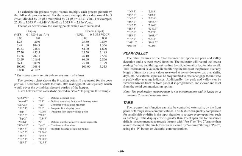
To calculate the process (input) values, multiply each process percent bythe full scale process input. For the above example this value would be 5(volts) divided by 36 (ft.) multiplied by 24 (ft.) = 3.333 VDC. For example,25.5% x 3.333 V = 0.849 V, 86.0% x 3.333 V = 2.866 V, etc.
The tables below show the scaling points which were calculated.
Display Process (Input)(%FS, 0-1680.4 cu. ft.*) (%FS, 0-3.333 VDC*)
0.00 0.0 0.00 0.0001.25 20.0 25.50 0.8496.49 104.3 41.00 1.36615.33 246.5 54.00 1.80027.70 455.5 65.50 2.18343.66 702.3 76.10 2.53663.19 1016.4 86.00 2.86686.41 1389.9 95.40 3.179100.00 1608.4 100.00 3.3335.000 4019.2
* The values shown in this column are user calculated.
The previous chart shows the 9 scaling points (8 segments) for the coneportion. The bottom line lists the final, 10th scaling point (9th segment), whichwould cover the cylindrical (linear) portion of the hopper.
Listed below are the values to be entered in “Pro 2” to program this example.
“dECPNt” - “0.0” - Defines decimal point
“round ” - “0.1” - Defines rounding factor and dummy zeros
“SCALE” - “yes” - Continue with scaling program
“dSP 1” - “0.0” - Program first display point
“Inp 1” - “0.000” - Program first input voltage point
“dSP 2” - “20.0”
“Inp 2” - “0.849”
“SEGt” - “9” - Defines number of active linear segments
“SCALE” - “yes” - Continue with scaling
“dSP 3” - “104.3” - Program balance of scaling points
“INP 3” - “1.366”
“dSP 4” - “246.5”
“INP 4” - “1.800”
“dSP 5” - “455.5”
“INP 5” - “2.183”
“dSP 6” - “702.2”
“INP 6” - “2.536”
“dSP 7” - “1016.4”
“INP 7” - “2.866”
“dSP 8” - “1389.9”
“INP 8” - “3.179”
“dSP 9” - “1608.4”
“INP 9” - “3.333”
“DSP 10” - “4019.2”
“INP 10” - “5.000”
PEAK/VALLEY
The other features of the totalizer/linearizer option are peak and valleydetection and a re-zero (tare) function. The indicator will record the lowestreading (valley) and the highest reading (peak), automatically, for later recall.This information is valuable in monitoring the limits of the process over anylength of time since these values are stored at power-down to span over shifts,days, etc. An external input can be programmed to reset or engage the unit intoa peak/valley reading indicator. Additionally, the peak and valley can beviewed and reset from the front panel, if so programmed, and viewed and resetfrom the serial communication option.
Note: The peak/valley measurement is not instantaneous and is based on anominal 2 second response time.
TARE
The re-zero (tare) function can also be controlled externally, by the frontpanel or through serial communications. This feature can quickly compensatefor small shifts or drifts in the input signal or to re-zero every operation, suchas batching. If the display error is greater than 1% of span due to transducerdrift, it is recommended to rescale the unit with “Pro 1” or “Pro 2”, rather thanre-zero the input. The tare buffer can be cleared by “walking” through “Pro 2”,using the “P” button or via serial communications.
-28-
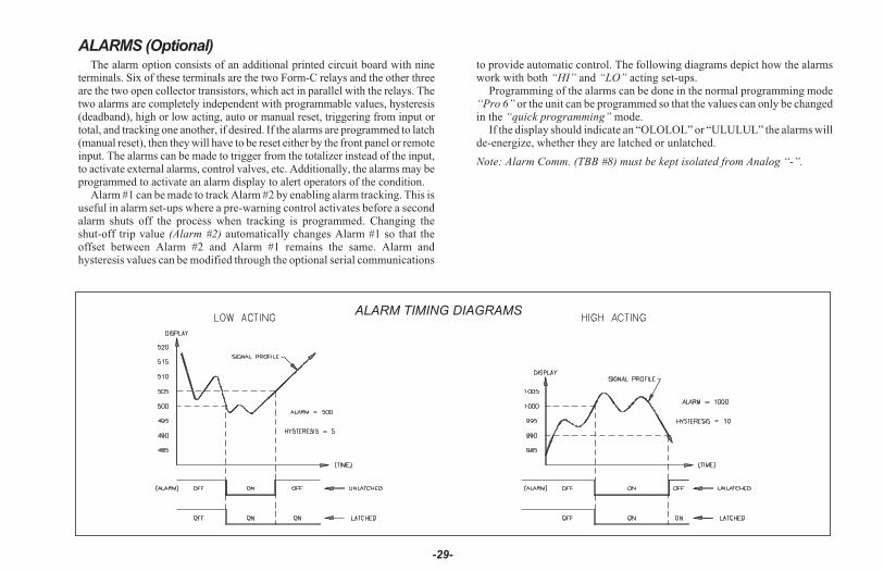
ALARMS (Optional)The alarm option consists of an additional printed circuit board with nine
terminals. Six of these terminals are the two Form-C relays and the other threeare the two open collector transistors, which act in parallel with the relays. Thetwo alarms are completely independent with programmable values, hysteresis(deadband), high or low acting, auto or manual reset, triggering from input ortotal, and tracking one another, if desired. If the alarms are programmed to latch(manual reset), then they will have to be reset either by the front panel or remoteinput. The alarms can be made to trigger from the totalizer instead of the input,to activate external alarms, control valves, etc. Additionally, the alarms may beprogrammed to activate an alarm display to alert operators of the condition.
Alarm #1 can be made to track Alarm #2 by enabling alarm tracking. This isuseful in alarm set-ups where a pre-warning control activates before a secondalarm shuts off the process when tracking is programmed. Changing theshut-off trip value (Alarm #2) automatically changes Alarm #1 so that theoffset between Alarm #2 and Alarm #1 remains the same. Alarm andhysteresis values can be modified through the optional serial communications
to provide automatic control. The following diagrams depict how the alarmswork with both “HI” and “LO” acting set-ups.
Programming of the alarms can be done in the normal programming mode“Pro 6” or the unit can be programmed so that the values can only be changedin the “quick programming” mode.
If the display should indicate an “OLOLOL” or “ULULUL” the alarms willde-energize, whether they are latched or unlatched.
Note: Alarm Comm. (TBB #8) must be kept isolated from Analog “-”.
-29-
ALARM TIMING DIAGRAMS

20 mA CURRENT LOOP SERIAL COMMUNICATIONS (Optional)
GENERAL DESCRIPTION
The serial communication option is a half-duplex, two-way, 20 mA loop thatcan connect to a variety of printers, computers, terminals and controllers to suitmany data-polling or automatic operation applications. The indicator respondsto a host of commands, including change alarm value, reset totalizer andtransmit input value. Two loops are required for all hook-ups; a transmit(out-going data) loop and a receive (in-coming data) loop. Since the indicatormonitors the receive loop for a busy signal (current interrupted) whiletransmitting, the receive loop must be connected even if the indicator istransmitting only, such as to a printer. A built-in 20 mA source can be used in thetransmit loop (only) by connecting the current return wire to -20 mA SRC.,instead of SO+. To bypass the built-in current source, make transmit loopconnections to SO+ and SO-. Additionally, multiple units and other Red LionControls instruments can be serially addressed, up to a maximum of 99 units.(The actual number in a single loop is limited by the serial hardwarespecifications.) To eliminate problems with ground loops, the serial circuitry isisolated from both signal common and output common. Optional 20 mA toRS232C and 20 mA to RS422 converter modules expand the unit’s flexibility.
Note: When operating the unit with a printer, the receive loop of the indicatormust have current flowing into it before transmission can take place.
COMMUNICATION FORMAT
Data is sent by switching current on and off in the loop and is received bymonitoring the switching action and interpreting the codes that are transmitted.In order for data to be correctly interpreted, there must be identical formats andbaud rates among the communicating equipment. The only format availablewith this indicator is 1 start bit, 7 data bits, 1 odd parity bit and 1 stop bit. Thebaud rates are programmable and the choices are: 300, 600, 1200 and 2400.
Before serial communication can take place, the indicator must beprogrammed to the same baud rate as the connected equipment. In addition, theloop address number, print options and full or abbreviated transmission must beprogrammed. If only one indicator is to be used, then a loop address number of“0” may by used, to eliminate the requirement for the address specifier whensending a command. If more than one indicator is on the loop, assignment ofunique addresses, other than zero, for each indicator is recommended. Validaddresses of 0 to 99 may be assigned, but the built-in current source, if used, iscapable of driving up to 7 units. Additional drive capability may be afforded byan external current source with a higher compliance voltage. Refer toprogramming section “Pro 7” to program the serial option.
-30-
DATA FORMAT-10 BIT FRAME [300, 600, 1200, 2400 Baud]

SENDING COMMANDS TO THE IMD1
When sending commands to the unit, a command string must beconstructed. The command string may consist of command codes, valueidentifiers, and numerical data. Below is a table outlining the codes theindicator will recognize.
COMMAND FUNCTIONS
T transmits the requested information specified by the identifier(A-I, K, & L)
V change a value specified by the identifier (C-F, K, & L)
N address a particular indicator in a multiple unit loop (0-99)
R reset a value specified by the identifier (B-D, G, H, I, & J)
P print per programmable print options (A-I)
VALUE IDENTIFIERS SERIAL MNEMONICS
A input or process value INP
B totalizer TOT
C alarm #1 AL1
D alarm #2 AL2
E hysteresis #1 HS1
F hysteresis #2 HS2
G peak reading PEK
H valley reading VAL
I zero tare TAR
J tare input --
K analog low ANL
L analog high ANH
Note: RJ - tares the input (re-zeros). When the input is tared (via front panel or“RJ”) the amount is stored in the tare reading (I). Ex. When a tare isperformed, the display reads “5.0”, the tare value will be “-00005.0” (andthe display will show 0.0).A command string is constructed by using the above commands and
identifiers along with any data values that are required. The indicator willaccept “+” or “-” in front of the data value. Numbers without “+” areunderstood to be positive. Leading zeros can be eliminated and both lower andupper case characters are accepted. The address command is used to allow a
command to be directed to a specific unit on the loop. If the indicator isassigned an address of “0”, transmission of the address command is notrequired. This is done where only one indicator is in the loop.
The command string is constructed in a specific logical sequence. Theindicator will reject command strings that do not conform. Only one operationcan be performed per command string. Below is a description of how toconstruct a command string.1. If the indicator has an address other than zero, the first two characters of the
string must consist of the address command (N) followed by the unitaddress number (0-99). If the indicator has an address of 0, the addresscommand is optional.
2. The next two characters in the string are the actual command the indicatormust perform and the identifier on which it operates. The command P -print, has an implied operation and needs no value identifier.
3. If the change value command is being used (V), the next characters in thestring after the value identifier, are the numerical data. When sendingnumerical data, such as change an alarm value, the correct number of digitsto the right, must be included. As an example, to change an alarm valuefrom 750.2 to 500.0. Sending 500 would cause the indicator to see 50.0 andchange the alarm value accordingly.
4. All commands must be terminated by an asterisk (*). The indicator will notrespond to any other code. Carriage return and line feed are not validterminators and should be suppressed with the character “;”, if using aBASIC print statement (ex. Print “N9TA*”;).
COMMAND STRING EXAMPLESIndicator with address 3, transmit input reading.
N3TA*Indicator with address 0, change alarm #1 to 1500.
VC1500*Indicator with address 1, reset totalizer.
N1RB*Indicator with address 99, print the print options.
N99P*Indicator with address 0, zero tare value.
RI*
-31-
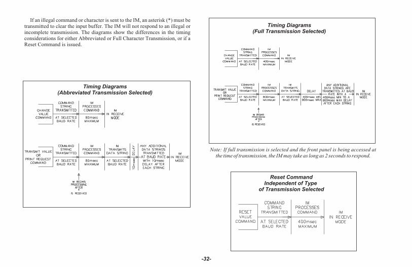
If an illegal command or character is sent to the IM, an asterisk (*) must betransmitted to clear the input buffer. The IM will not respond to an illegal orincomplete transmission. The diagrams show the differences in the timingconsiderations for either Abbreviated or Full Character Transmission, or if aReset Command is issued.
Note: If full transmission is selected and the front panel is being accessed atthe time of transmission, the IM may take as long as 2 seconds to respond.
-32-
Timing Diagrams(Abbreviated Transmission Selected)
Timing Diagrams(Full Transmission Selected)
Reset CommandIndependent of Type
of Transmission Selected
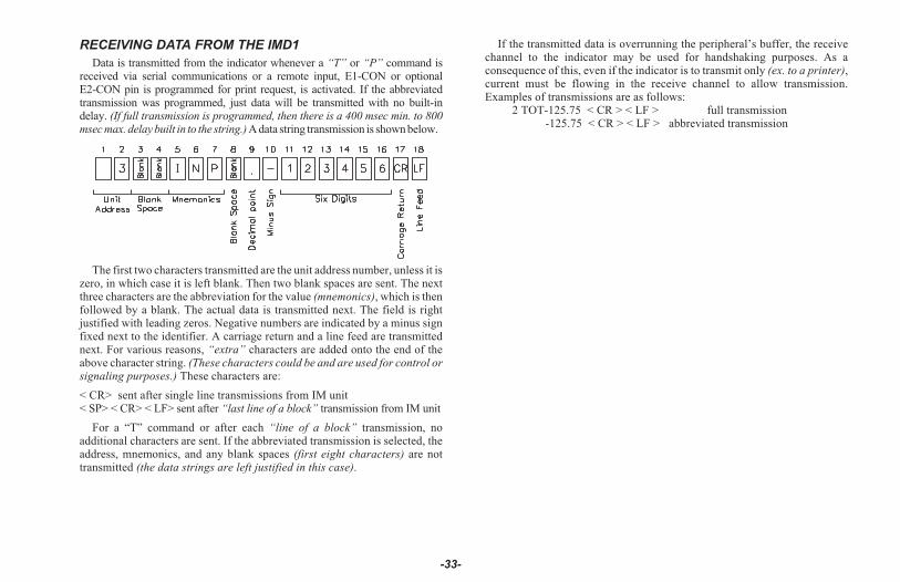
RECEIVING DATA FROM THE IMD1
Data is transmitted from the indicator whenever a “T” or “P” command isreceived via serial communications or a remote input, E1-CON or optionalE2-CON pin is programmed for print request, is activated. If the abbreviatedtransmission was programmed, just data will be transmitted with no built-indelay. (If full transmission is programmed, then there is a 400 msec min. to 800msec max. delay built in to the string.) A data string transmission is shown below.
The first two characters transmitted are the unit address number, unless it iszero, in which case it is left blank. Then two blank spaces are sent. The nextthree characters are the abbreviation for the value (mnemonics), which is thenfollowed by a blank. The actual data is transmitted next. The field is rightjustified with leading zeros. Negative numbers are indicated by a minus signfixed next to the identifier. A carriage return and a line feed are transmittednext. For various reasons, “extra” characters are added onto the end of theabove character string. (These characters could be and are used for control orsignaling purposes.) These characters are:
< CR> sent after single line transmissions from IM unit< SP> < CR> < LF> sent after “last line of a block” transmission from IM unit
For a “T” command or after each “line of a block” transmission, noadditional characters are sent. If the abbreviated transmission is selected, theaddress, mnemonics, and any blank spaces (first eight characters) are nottransmitted (the data strings are left justified in this case).
If the transmitted data is overrunning the peripheral’s buffer, the receivechannel to the indicator may be used for handshaking purposes. As aconsequence of this, even if the indicator is to transmit only (ex. to a printer),current must be flowing in the receive channel to allow transmission.Examples of transmissions are as follows:
2 TOT-125.75 < CR > < LF > full transmission-125.75 < CR > < LF > abbreviated transmission
-33-
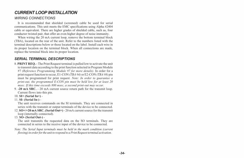
CURRENT LOOP INSTALLATION
WIRING CONNECTIONS
It is recommended that shielded (screened) cable be used for serialcommunications. This unit meets the EMC specifications using Alpha #2404cable or equivalent. There are higher grades of shielded cable, such as, fourconductor twisted pair, that offer an even higher degree of noise immunity.
When wiring the 20 mA current loop, remove the bottom terminal block(TBA), located on the rear of the unit. Refer to the numbers listed with theterminal descriptions below or those located on the label. Install each wire inits proper location on the terminal block. When all connections are made,replace the terminal block into its proper location.
SERIAL TERMINAL DESCRIPTIONS
8. PRINT REQ. - The Print Request terminal is pulled low to activate the unitto transmit data according to the print function selected in Program Module#7 (Reference Programming Module #7 for more details). In order for aprint request function to occur, E1-CON (TBA #4) or E2-CON (TBA #8) pinmust be programmed for print request. Note: In order to guarantee aprint-out, the programmed E-CON pin must be held low for at least 20msec. If this time exceeds 800 msec, a second print-out may occur.
9. -20 mA SRC. - 20 mA current source return path for the transmit loop.Current flows into this pin.
10. SI+ (Serial In+) -11. SI- (Serial In-) -
The unit receives commands on the SI terminals. They are connected inseries with the transmit or output terminals of the device to be connected.
12. SO+/+20 mA SRC. (Serial Out+) - 20 mA current source for the transmitloop (internally connected).
13. SO- (Serial Out-) -The unit transmits the requested data on the SO terminals. They areconnected in series to the receive input of the device to be connected.
Note: The Serial Input terminals must be held in the mark condition (currentflowing) in order for the unit to respond to a Print Request terminal activation.
-34-

SERIAL COMMUNICATIONS EXAMPLE
-35-
PROCESS CONTROLLING SYSTEMSix Model IMD1s with Serial Communication Option are
used to monitor and control humidity levels of six separategreenhouses at an Agricultural Research and DevelopmentCenter. One IMD1 is located at each building. Thecommunication lines are run to a computer located in themain office.
The drawing below shows the Current Loop set-up. EachIMD1 is given an address and programmed accordingly(Program Module #7). A baud rate of 1200 is selected.
An application program is written, which sends andretrieves data from the IMD1s.
Note: On all IM indicators, the SO+ and the +20 mA SRCare connected internally. Therefore it is not necessary tohave the +20 mA SRC terminal tied to any other terminalon the unit if that unit is serving as the loop supply source.

RE-TRANSMITTED ANALOG OUTPUT (Optional)The re-transmitted analog output option transmits a digitally
programmable 4 to 20 mA or 0 to 10 VDC signal to drive chart recorders,remote indicators and controllers. The option is contained on the upper PCBand has two outputs, “ANALOG-” (TBB #10) and “ANALOG+” (TBB #11)and is self-powered (active) with a compliance of 10 VDC. The analog “-”output is isolated from the signal input common, eliminating problems fromground loops. Programming of the option is performed in “Pro 8” of thenormal programming mode. Display values are simply keyed in to provide a 4mA or 0 VDC output, “AN-LO”, and a 20 mA or 10 VDC output, “AN-HI”.The analog output then follows the assigned value and as such will updateevery measurement cycle. Nonstandard current or voltage ranges can besupported by calculating the slope and intercept of the display/output andcalculating the required display values at 4 mA (0 VDC) and 20 mA (10 VDC).
Reverse action can be achieved by programming a “high” display value for“AN-LO” and a “low” display value for “AN-HI”.
If the display should indicate an “OLOLOL” or “ULULUL” the analogoutput will go to 20 mA (10 VDC) for an open and 4 mA (0 VDC) for a short.
Note: Analog “-” must be kept isolated from alarm comm. (TBB #8).
-36-
ANALOG OUTPUT DIAGRAMS
ANALOG OUTPUT CALIBRATION
Although the analog output has been calibrated at the factory, zero and spanadjustments are provided to compensate for small offsets and drifts. If excessivedrift is noticed, the following calibration procedure may be performed.
Scale the analog output by entering an arbitrarily larger display value for“AN-HI” than for “AN-LO” in “PRO 8”.
Note: Set the analog output source assignment for input.
4 to 20 mA CALIBRATIONExit the programming mode and apply a signal to the input of the indicator
so that the display reading is below that of the value entered for “AN-LO”.Adjust the zero potentiometer (right side) so that exactly 4.00 mA flows, asverified by an accurate ammeter. Next, apply a signal to the indicator so thatthe display reading is above that of the value entered for “AN-HI”. (SeeAppendix “B” for maximum input voltage.) Adjust the span potentiometer(left side) so that 20.00 mA is flowing. Repeat the zero and span adjustmentsuntil both are accurate. Analog output calibration is complete.
0 to 10 VDC CALIBRATIONExit the programming mode and apply a (temperature)/(resistance) to the
input of the indicator so that the display reading is below that of the valueentered for “AN-LO”. Adjust the zero potentiometer (right side) so thatexactly 0.00 VDC flows, as verified by an accurate voltmeter. Next, apply a(temperature)/ (resistance) to the indicator so that the display reading is abovethat of the value entered for “AN-HI”. (See Appendix “B” for maximum inputvoltage.) Adjust the span potentiometer (left side) so that 10.00 VDC isflowing. Repeat the zero and span adjustments until both are accurate. Analogoutput calibration is complete.
-37-

APPENDIX “A” - INSTALLATION & CONNECTIONSINSTALLATION ENVIRONMENT
The unit should be installed in a location that does not exceed the maximumoperating temperature and provides good air circulation. Placing the unit neardevices that generate excessive heat should be avoided.
The bezel should be cleaned only with a soft cloth and neutral soap product.Do NOT use solvents. Continuous exposure to direct sunlight may acceleratethe aging process of the bezel.
Do not use tools of any kind (screwdrivers, pens, pencils, etc.) to operatethe keypad of the unit. Before installing the IM into the panel, the user shouldfirst become familiar with the unit. It may also be desirable to program theunit for the application. When programming is complete, all parameters willbe saved in nonvolatile memory. The Program Disable (PGM.DIS.) terminalshould be connected to COMM. to prevent accidental or unauthorizedprogramming changes.
-38-
PANEL INSTALLATION The unit meets NEMA 4/IP65 requirements for indoor use, whenproperly installed. The units are intended to be mounted into an enclosedpanel. Two mounting clips and screws are provided for easy installation.Consideration should be given to the thickness of the panel. A panel whichis too thin may distort and not provide a water-tight seal. (Recommendedmin. panel thickness is 1/8" [3.2 mm].)
Cut the panel opening to the specified dimensions. Remove burrs andclean around the panel opening. Slide the panel gasket over the rear of theunit to the back of the bezel. Insert the unit into the panel. As depicted in thedrawing, install the screws into thenarrow end of the mounting clips.Thread the screws into the clips untilthe pointed end just protrudes throughthe other side. Install each of themounting clips by inserting the widelip of the clips into the wide end of thehole, located on either side of the case.Then snap the clip onto the case.Tighten the screws evenly to applyuniform compression, thus providing awater-tight seal.
CAUTION: Only minimum pressure is required to seal panel. Do NOTovertighten screws.
SELECT AC POWER (115/230 VAC)
The AC power to the unit must be selected for either 115 VAC or 230 VAC.The selector switch is located through an access slot on the side of the case (Seefigure above or label on case). The unit is shipped from the factory with theswitch in the 230 VAC position.
CAUTION: Make sure the AC selector switch is set to theappropriate position before applying power to the unit. Damageto the unit may occur if the AC selector switch is set incorrectly.
EMC INSTALLATION GUIDELINES
Although Red Lion Controls products are designed with a high degree ofimmunity to Electromagnetic Interference (EMI), proper installation andwiring methods must be followed to ensure compatibility in each application.The type of the electrical noise, source or coupling method into a unit may bedifferent for various installations. Cable length, routing, and shieldtermination are very important and can mean the difference between asuccessful or troublesome installation. Listed are some EMI guidelines for asuccessful installation in an industrial environment.
1. A unit should be mounted in a metal enclosure, which is properly connectedto protective earth.
2. Use shielded cables for all Signal and Control inputs. The shield connectionshould be made as short as possible. The connection point for the shielddepends somewhat upon the application. Listed below are therecommended methods of connecting the shield, in order of theireffectiveness.a. Connect the shield to earth ground (protective earth) at one end where
the unit is mounted.b. Connect the shield to earth ground at both ends of the cable, usually
when the noise source frequency is over 1 MHz.3. Never run Signal or Control cables in the same conduit or raceway with AC
power lines, conductors, feeding motors, solenoids, SCR controls, andheaters, etc. The cables should be run through metal conduit that is properly grounded. This is especially useful in applications where cable runs arelong and portable two-way radios are used in close proximity or if theinstallation is near a commercial radio transmitter. Also, Signal or Controlcables within an enclosure should be routed as far away as possible fromcontactors, control relays, transformers, and other noisy components.
4. Long cable runs are more susceptible to EMI pickup than short cable runs.5. In extremely high EMI environments, the use of external EMI suppression
devices such as Ferrite Suppression Cores for signal and control cables iseffective. The following EMI suppression devices (or equivalent) arerecommended:
Fair-Ri te part number 0443167251 (Red Lion Controls #FCOR0000)
Line Filters for input power cables:
Schaffner # FN2010-1/07 (Red Lion Controls # LFIL0000)6. To protect relay contacts that control inductive loads and to minimize
radiated and conducted noise (EMI), some type of contact protectionnetwork is normally installed across the load, the contacts or both. The most effective location is across the load.a. Using a snubber, which is a resistor-capacitor (RC) network or metal
oxide varistor (MOV) across an AC inductive load is very effective atreducing EMI and increasing relay contact life.
b. If a DC inductive load (such as a DC relay coil) is controlled by atransistor switch, care must be taken not to exceed the breakdownvoltage of the transistor when the load is switched. One of the mosteffective ways is to place a diode across the inductive load. Most RedLion products with solid state outputs have internal zener diodeprotection. However external diode protection at the load is always agood design practice to limit EMI. Although the use of a snubber orvaristor could be used.Red Lion part numbers: Snubber: SNUB0000
Varistor: ILS11500 or ILS230007. Care should be taken when connecting input and output devices to the
instrument. When a separate input and output common is provided, theyshould not be mixed. Therefore a sensor common should NOT beconnected to an output common. This would cause EMI on the sensitiveinput common, which could affect the instrument’s operation.
Visit www.redlion.net/emi for more information on EMI guidelines, Safetyand CE issues as they relate to Red Lion products.
-39-
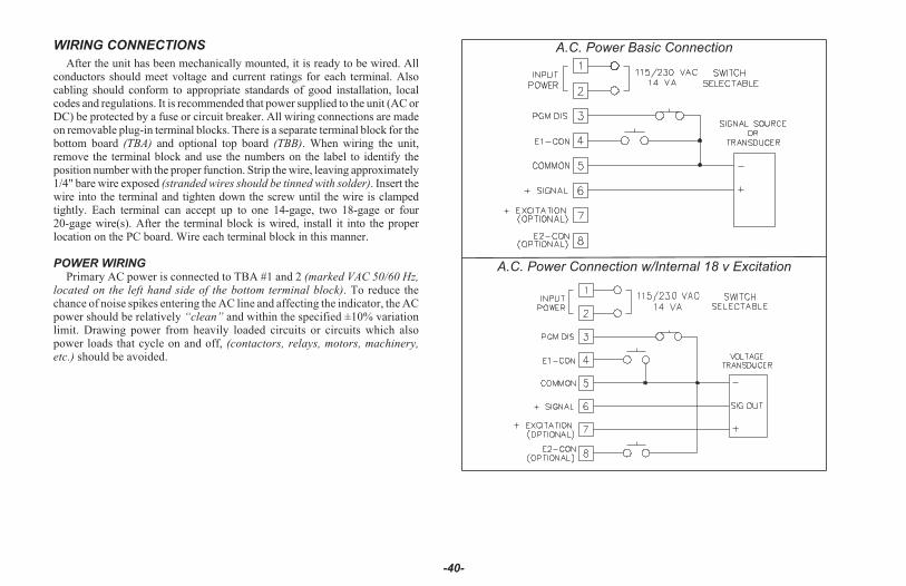
WIRING CONNECTIONS
After the unit has been mechanically mounted, it is ready to be wired. Allconductors should meet voltage and current ratings for each terminal. Alsocabling should conform to appropriate standards of good installation, localcodes and regulations. It is recommended that power supplied to the unit (AC orDC) be protected by a fuse or circuit breaker. All wiring connections are madeon removable plug-in terminal blocks. There is a separate terminal block for thebottom board (TBA) and optional top board (TBB). When wiring the unit,remove the terminal block and use the numbers on the label to identify theposition number with the proper function. Strip the wire, leaving approximately1/4" bare wire exposed (stranded wires should be tinned with solder). Insert thewire into the terminal and tighten down the screw until the wire is clampedtightly. Each terminal can accept up to one 14-gage, two 18-gage or four20-gage wire(s). After the terminal block is wired, install it into the properlocation on the PC board. Wire each terminal block in this manner.
POWER WIRINGPrimary AC power is connected to TBA #1 and 2 (marked VAC 50/60 Hz,
located on the left hand side of the bottom terminal block). To reduce thechance of noise spikes entering the AC line and affecting the indicator, the ACpower should be relatively “clean” and within the specified ±10% variationlimit. Drawing power from heavily loaded circuits or circuits which alsopower loads that cycle on and off, (contactors, relays, motors, machinery,etc.) should be avoided.
-40-
A.C. Power Basic Connection
A.C. Power Connection w/Internal 18 v Excitation

SIGNAL WIRINGMeter signal input common is not isolated from PGM.DIS.,
E1-CON, E2-CON and +EXC. In order to preserve the safety ofthe meter application, the signal input common must be limited to50 V with respect to protective earth ground. If the signal inputcommon cannot be suitably isolated from protective earth groundin order to meet this requirement, it must be connected directly toprotective earth ground.Meter inputs/outputs, other than relay alarms, can not be
connected to operator accessible circuitry when hazardous
live voltage (above 30 V rms, 42.4 V peak) is applied to meter
signal input. Hazardous live circuits should not be accessible
to non-trained personnel.
Interconnection circuitry should not be connected to any useraccessible parts or circuitry.
For Signal Sources Not Requiring Excitation:
Select proper input range jumper. Connect the “+” lead of the process signalto TBA #6, “+SIGNAL”, and the “-” lead of the signal to TBA #5, “COMM”.Refer to the transducer manufacturer’s data sheet supplied with the transducerfor proper connections.Transducers Requiring Excitation:
Select proper input range jumper. Connect the “+” lead of the transducer toTBA #7, “+EXCITATION”, the “-” lead to TBA #5, “COMM”, and signallead to TBA #6, “+SIGNAL”. Refer to the transducer manufacturer’s datasheet supplied with the transducer for proper connections.Note: The common of the excitation voltage is connected internally to
“COMM” (TBA #5).
USER INPUT WIRINGUser inputs (PGM.DIS., E1-CON, and optional E2-CON) are digital inputs
that are active when connected to TBA #5 Common. Any form of mechanicalswitch, sinking collector logic with less than 0.7 V saturation may be used.The use of shielded cable is recommended. Follow the Additional EMCInstallation Guidelines for shield connection.
OUTPUT WIRINGRELAY CONNECTIONS
To prolong contact life and suppress electrical noise interference due to theswitching of inductive loads, it is good installation practice to install a snubberacross the contactor. Follow the manufacturer’s instructions for installation.Note: Snubber leakage current can cause some electro-mechanical devices to
be held ON.
SELECTING THE INPUT RANGE
To select or change the input range the following steps apply:
1. Remove terminal block “A” (TBA).2. Using a pair of long nose pliers, remove the jumper and re-position it in the
location corresponding to the range being selected. (When the unit isshipped from the factory, the jumper is in position #4.)Looking at the rear of the unit, the position numbers and their
corresponding ranges are as follows, from left to right:POSITION #1 ±2 VDCPOSITION #2 ±20 VDCPOSITION #3 ±200 VDCPOSITION #4 ±300 VDC
3. Replace terminal block “A” (TBA). Input range selection is now complete.
Although the unit has been factory calibrated for all ranges, greateraccuracy can be achieved by calibrating the individual range in use.
(Refer to “PRO 1” for scaling)
-41-
REAR VIEW OF IMD1 WITH TBA TERMINALS REMOVED

APPENDIX “B” - SPECIFICATIONS AND DIMENSIONS1. DISPLAY: 6-digit, 0.56" (14.2 mm) High LED, minus sign displayed for
negative values. Flashing display during totalizer overflow. “......” displayedduring input display out of range. “OLOLOL” displayed for input overloadand “ULULUL” displayed for underload (negative overload).
2. POWER REQUIREMENTS:
A.C. Power: Switch Selectable 115/230 VAC, 10%, 50/60 Hz, 14 VAIsolation: 2300 Vrms for 1 min. to all inputs and outputs.
Working Voltage: 300 V max., CATII3. CONTROLS: Three front panel push buttons for modifying alarm values
and indicator set-up. Two external inputs for disabling the front panel andcontrolling programmable functions.
4 . INPUT RANGE/RESOLUTION, ACCURACY, INPUT
IMPEDANCE AND MAXIMUM INPUT LEVEL:
VOLTAGE ACCURACY R(ohms) MAXIMUMRANGES/RESOLUTION OF FULL SCALE INPUT
±2.0000/0.1 mVDC 0.025% 1 MEG 70 VDC±20.000/1 mVDC 0.1% 1 MEG 300 VDC±200.00/10 mVDC 0.1% 1 MEG 300 VDC±300.0/100 mVDC 0.1% 1 MEG 300 VDC
Working Voltage: 50 V max., CATIRelative Humidity: Less then 85% RH
Note: Any individual range may be recalibrated to 0.025% accuracy withappropriate calibration equipment (refer to “PRO 1” for scaling).
5. PROGRAMMABLE DISPLAY READING RANGE: -99,999 to999,999
6. READING RATE: 2.5 readings/second7. RESPONSE TIME: 2 seconds to settle for step input (increases with
programmable digital filtering)8. TOTALIZER: Front panel button for input/total display select.
Programmable time-base, scale factor (0.001 - 100.000) and low-endcutout. Maximum response time is 0.2 seconds.
9. E1-CON & E2-CON: External remote inputs which allow activation ofvarious functions (reset total, peak indicator mode, trigger mode, etc.).VIL = 0.8 VMAX; VIH = 2.0 VMIN; Response Time = 0.2 sec maximum.
10. NORMAL MODE REJECTION: 35 dB at 50/60 Hz (may be improvedby programmable digital filtering)
11. COMMON MODE REJECTION: 120 dB, DC to 50/60 Hz12. ENVIRONMENTAL CONDITIONS:
Operating Temperature Range: 0° to 50°CStorage Temperature Range: -40° to 80°CSpan Temperature Coeff.: 50 ppm/°CZero Temperature Coeff.: 1 uV/°COperating and Storage Humidity: 85% max. Relative humidity(non-condensing) from 0°C to 50°C.Altitude: Up to 2000 meters
13. EXCITATION (Optional): 18 VDC @ 60 mA max. ±5%
-42-
DIMENSIONS In inches (mm)
Note: Recommended minimum clearance (behind the panel) for mounting clip installation is 2.1" (53.3) H x 5.5" (140) W.
PANEL CUT-OUT
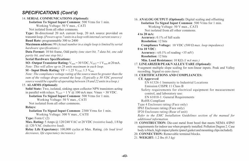
SPECIFICATIONS (Cont’d)14. SE RIAL COM MU NI CA TIONS (Op tional):
Iso la tion To Sig nal In put Com mon: 500 Vrms for 1 min. Work ing Volt age: 50 V max., CATI
Not iso lated from all other com mons.Type: Bi- directional 20 mA cur rent loop, 20 mA source pro vided ontrans mit loop. (Pow ers up to 7 units in a loop with in ter nal cur rent source.)Baud Rate: pro gram ma ble 300 to 2400Maxi mum ad dress: 99 (Ac tual number in a sin gle loop is lim ited by se rialhard ware speci fi ca tions.)Data For mat: 10 bit frame, Odd par ity (one start bit, 7 data bit, one oddpar ity bit, and one stop bit.)Se rial Hard ware Speci fi ca tions:SO - Out put Tran sis tor Rat ing: Vmax = 30 VDC, VSAT = 1 Vmax at 20 mA.Note: This will al low up to 28 units maxi mum in each loop.SI - In put Di ode Rat ing: VF = 1.25 VTYP; 1.5 Vmax
Note: The com pli ance volt age rat ing of the source must be greater than thesum of the volt age drops around the loop. (Typi cally a 30 VDC pow eredsource would be ca pa ble of op er at ing be tween 18 and 22 units in a loop.)
15. ALARMS (Op tional):Solid State: Two, iso lated, sink ing open col lec tor NPN tran sis tors act ingin par al lel with re lays. VSAT = 1 V @ 100 mA max: Vmax = 30 VDC.
Isolation To Signal Input Common: 500 Vrms for 1 min. Working Voltage: 50 V max., CATI
Not isolated from all other commons.Re lays:
Isolation To Signal Input Common: 2300 Vrms for 1 min. Working Voltage: 300 V max., CATII
Type: Form C (2)Max. Rat ing: 5 Amps @ 120/240 VAC or 28 VDC (re sis tive load), 1/8 hp@ 120 VAC (in duc tive load).Re lay Life Ex pec tancy: 100,000 cy cles at Max. Rat ing. (As load levelde creases, life ex pec tancy in creases.)
16. ANA LOG OUT PUT (Op tional): Digi tal scal ing and off set tingIsolation To Signal Input Common: 500 Vrms for 1 min.
Working Voltage: 50 V max., CATINot isolated from all other commons.
4 to 20 mA:Ac cu racy: 0.1% of full scaleReso lu tion: 12 bitsCom pli ance Volt age: 10 VDC (500 W max. loop im ped ance)
0 to 10 VDC:Ac cu racy: ±(0.1% of read ing +35 mV)Reso lu tion: 12 bitsMin. Load Re sis tance: 10 KW (1 mA max.)
17. LINE AR IZER/PEAK/VAL LEY/TARE (Op tional): 9- segment mul ti ple slope scal ing for non- linear in puts. Peak and Val leyre cord ing. Sig nal re- zero (tare).
18. CER TI FI CA TIONS AND COM PLI ANCES: CE Approved
EN 61326-1 Immunity to Industrial LocationsEmission CISPR 11 Class B
Safety requirements for electrical equipment for measurementcontrol, and laboratory use:EN 61010-1: General Requirements
RoHS CompliantType 4 Enclosure rating (Face only)IP65 Enclosure rating (Face only)IP20 Enclosure rating (Rear of unit)Re fer to the EMC In stal la tion Guide lines sec tion of the man ual forad di tional in for ma tion.
19. CON STRUC TION: Die- cast metal front bezel that meets NEMA 4/IP65re quire ments for in door use when prop erly in stalled. Pol lu tion De gree 2. Casebody is black, high im pact plas tic (panel gas ket and mount ing clips in cluded).
20. CON NEC TION: Re mov able ter mi nal blocks.21. WEIGHT: 1.2 lbs (0.5 kg)
-43-
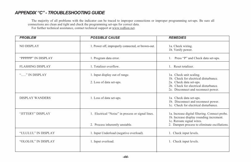
APPENDIX “C” - TROUBLESHOOTING GUIDE
-44-
The ma jor ity of all prob lems with the in di ca tor can be traced to im proper con nec tions or im proper pro gram ming set- ups. Be sure allcon nec tions are clean and tight and check the pro gram ming set- ups for cor rect data.
For further technical assistance, contact technical support at www.redlion.net.
PROB LEM POS SI BLE CAUSE REME DIES
NO DIS PLAY 1. Power off, im prop erly con nected, or brown- out. 1a. Check wir ing.1b. Ver ify power.
“PPPPPP” IN DIS PLAY 1. Pro gram data er ror. 1. Press “P” and Check data set- ups.
FLASH ING DIS PLAY 1. To talizer over flow. 1. Re set to talizer.
“......” IN DIS PLAY 1. In put dis play out of range. 1a. Check unit scal ing.1b. Check for elec tri cal dis tur bance.
2. Loss of data set- ups. 2a. Check data set- ups.2b. Check for elec tri cal dis tur bance.2c. Dis con nect and re con nect power.
DIS PLAY WAN DERS 1. Loss of data set- ups. 1a. Check data set- ups.1b. Dis con nect and re con nect power.1c. Check for elec tri cal dis tur bance.
“JIT TERY” DIS PLAY 1. Elec tri cal “Noise” in pro cess or sig nal lines. 1a. In crease digi tal fil ter ing. Con nect probe.1b. In crease dis play round ing in cre ment.1c. Re route sig nal wires.2. Dampen pro cess to elimi nate os cil la tions.2. Proc ess in her ently un sta ble.
“ULU LUL” IN DIS PLAY 1. In put Un der load (nega tive over load). 1. Check in put lev els.
“OLOLOL” IN DIS PLAY 1. In put over load. 1. Check in put lev els.

-45-
Pro gram ming of the in di ca tor is di vided into modu lar steps. Each mod uleis a short se quence of data en tries. The front panel but tons “UP” and“DOWN”, (shown as “ar rows” on the front panel) are used to change thedata and set- ups, while the “P” but ton is used to save or en ter the data. Af terpress ing “P” which gains en try into the pro gram ming mode, thepro gram ming mod ules are iden ti fied by the mes sage “Pro” and a number inthe dis play. “UP” and “DOWN” are used to se lect the de sired pro gram mingmod ule and “P” is used to en ter it. All of the sub se quent pro gram ming stepsfol low the same pro ce dure. The rear ter mi nal la beled “PGM. DIS.” must beun grounded to gain ac cess to pro gram ming.
The fol low ing ta ble lists the pro gram ming steps.
“Pro 0” - RE TURN TO MEAS URE MENT MODE
“Pro 1” - SCALE UNIT BY AP PLY ING SIG NAL“ dECPNt” - En ter dec i mal point for scaled dis play
“round” - En ter round ing fac tor and trail ing ze ros for scaled dis play
“SCALE” - *“dSP 1” - En ter dis play read ing for scal ing point #1
“INP 1” - Ap ply sig nal level for scal ing point #1
“dSP 2” - En ter dis play read ing for scal ing point #2
“INP 2” - Ap ply sig nal level for scal ing point #2
“SEGt” - *
“Pro 2” - SCALE UNIT BY KEY- IN SIG NAL LEVEL“ dECPNt” - En ter dec i mal point for scaled dis play
“round” - En ter round ing fac tor and trail ing ze ros for scaled dis play
“SCALE” - *“dSP 1” - En ter dis play read ing for scal ing point #1
“INP 1” - En ter sig nal level for scal ing point #1
“dSP 2” - En ter dis play read ing for scal ing point #2
“INP 2” - En ter sig nal level for scal ing point #2
“SEGt” - *
* - En tire se quence for this modu lar step is not shown (see re spec tivepro gram ming mod ule for fur ther de tails).
> This se quence may be sub ject to be ing locked- out due to other programmed se quences.
“Pro 3” - PRO GRAM FUNC TIONS AC CES SI BLE WITH FRONT PANEL LOCK OUT EN GAGED“dSP AL” - En able dis play alarms
“ENt AL” - En able en ter alarms >“dSPHYS” - En able dis play hys ter esis
“ENtHYS” - En able en ter hys ter esis >“rSt AL” - En able re set latched alarms
“dSPbUF” - En able dis play of peak/val ley read ings
“rStbUF” - En able re set of peak/val ley read ings >“SELdSP” - En able switch ing dis play be tween in put and to tal
“rSttOt” - En able re set to tal
“tArE” - En able re-zero (tare) of in put sig nal
“Pro 4” - PRO GRAM DIGI TAL FIL TER ING AND RE MOTE IN PUT FUNC TION
“FIL tEr” - En ter level of dig i tal fil ter ing
0 - no dig i tal fil ter ing
1 - nor mal fil ter ing
2 - in creased fil ter ing
3 - max i mum fil ter ing
“E1-CON” - En ter func tion of re mote in put (Re set/Hold)
0 - re-zero in put
1 - re set to tal
2 - re set and gate totalizer
3 - gate totalizer
4 - dis play hold
5 - re set peak/val ley
6 - re set peak and start peak in di ca tor
7 - re set val ley and start val ley in di ca tor
8 - re set latched alarms
9 - re set all alarms
10 - tog gle dis play be tween in put and to tal
11 - re-zero in put and totalize the tared val ues
12 - dis play hold with tare
13 - in stru ment read ing synchronization
14 - print re quest
“E2-CON” - Same func tions as E1-CON
AP PEN DIX “D” - PRO GRAM MA BLE FUNC TIONS

-46-
“Pro 5” - PRO GRAM TO TALIZER“dECPNt” - En ter dec i mal point for totalization
“tbASE” - En ter time base
“0” - sec ond
“1” - min ute
“2” - hour
“SCLFAC” - En ter mul ti ply ing scale fac tor
“Lo-cut” - En ter low-sig nal cut out
“Pro 6” - PRO GRAM ALARMS“trAc” - En able alarm value track ing
“dISP” - En able dis play alarm an nun ci a tors
“LAtC-1” - En able alarm #1 latch ing
“ASN-1” - En ter alarm #1 trig ger source (in put or to tal)
“AL-1” - En ter alarm #1 value
“HYS-1” - En ter hys ter esis value for alarm #1
“Act-1” - En ter alarm #1 ac tion (high or low)
“LAtC-2” - En able alarm #2 latch ing
“ASN-2” - En ter alarm #2 trig ger source (in put or to tal)
“AL-2” - En ter alarm #2 value
“HYS-2” - En ter hys ter esis value for alarm #2
“Act-2” - En ter alarm #2 ac tion (high or low)
“Pro 7” - PRO GRAM SE RIAL COM MU NI CA TIONS“bAud” - En ter baud rate
“AddrES” - En ter loop ad dress num ber (0-99)
“Print” - En ter print func tion, or “P” com mand
func tion through Se rial Op tion
0 - in put
1 - in put, peak/val ley, and tare
2 - in put and alarms
3 - in put, peak/val ley, alarms, hys ter esis, and tare
4 - to tal
5 - in put, to tal
6 - in put, to tal, peak/val ley, and tare
7 - to tal and alarms
8 - in put, to tal and alarms
9 - in put, to tal, peak/val ley, alarms,
hys ter esis, and tare
“FULL” - En able com plete or ab bre vi ated print ing
“Pro 8” - PRO GRAM RE- TRANSMITTED ANA LOG OUT PUT“ASIN” - Se lect source of an a log out put (in put or to tal)
“AN-Lo” - En ter 4 mA or 0 VDC dis play value
“AN-HI” - En ter 20 mA or 10 VDC dis play value
“Pro 9” - SERV ICE OP ERA TIONS (Pro tected by ac cess code)“Code 39” - Se rial hard ware (loop-back) test
“Code 48” - Ba sic in put cal i bra tion
“Code 66” - Re set pro gram ming to fac tory con fig u ra tion
AP PEN DIX “D” - PRO GRAM MA BLE FUNC TIONS (Cont’d)

-47-
APPENDIX “E” - USERS PROGRAMMING VALUES CHART
PRO GRAM MOD ULE #1Scaled By Sig nal Method
dECPNt
round
SCALE
dSP 1
INP 1
dSP 2
INP 2
Ad di tional scal ing points are NOT nec es sary, un less multi- segment line ari za tion is re quired.
dSP 3
INP 3
dSP 4
INP 4
dSP 5
INP 5
dSP 6
INP 6
dSP 7
INP 7
dSP 8
INP 8
dSP 9
INP 9
PRO GRAM MOD ULE #2Scaled By Key- In Method
dECPNt
round
SCALE
dSP 1
INP 1
dSP 2
INP 2
Ad di tional scal ing points are NOT nec es sary, un less multi- segment line ari za tion is re quired.
dSP 3
INP 3
dSP 4
INP 4
dSP 5
INP 5
dSP 6
INP 6
dSP 7
INP 7
dSP 8
INP 8
dSP 9
INP 9

-48-
APPENDIX “E” - USERS PROGRAMMING VALUES CHART (Cont’d)
PRO GRAM MOD ULE #3Front Panel Lock out
dSP AL
ENt AL
dSPHYS
ENtHYS
rSt AL
dSPbUF
rStbUF
SELdSP
rSttOt
tArE
PRO GRAM MOD ULE #4Digi tal Fil ter & Re mote In put Func tion
FIL tER
E1-CON
E2-CON
PRO GRAM MOD ULE #5In te gra tor/To talizer
dECPNt
tbASE
SCLFAC
Lo-cut
PRO GRAM MOD ULE #6Alarms
trAC
dISP
LAtC-1
ASN-1
AL-1
HyS-1
Act-1
LAtC-2
ASN-2
AL-2
HyS-2
Act-2
PRO GRAM MOD ULE #7Com mu ni ca tions
bAud
AddrES
FULL
PRO GRAM MOD ULE #8Ana log Out put
ASIN
AN-Lo
AN-HI

-49-
APPENDIX “F” - ORDERING INFORMATIONMODEL NO. DE SCRIP TION +18 VDC
EX CI TA TIONTO TALIZER/LINE AR IZER
PEAK/ VAL LEYTARE/E2- CON
DUALALARMS
SE RIALOUT PUT
ANA LOGOUT PUT
PART NUM BERS FORAVAIL ABLE SUP PLY
VOLT AGES
115/230 VAC
IMD1In tel li gent
Me ter For Dec adeVolt age In puts
NO NO NO NO NO IMD10060
YES NO NO NO NO IMD10160
YES NO YES NO NO IMD10162
YES YES NO NO NO IMD13160
YES YES NO YES NO IMD13161
YES YES YES NO NO IMD13162
YES YES NO NO 4 to 20 mA IMD13163
YES YES YES YES 4 to 20 mA IMD13167
YES YES YES YES 0 to 10 VDC IMD13169
IMD2In tel li gent
Me ter For Dec adeCur rent In puts
NO NO NO NO NO IMD20060
YES NO NO NO NO IMD20160
YES NO YES NO NO IMD20162
YES YES NO NO NO IMD23160
YES YES NO YES NO IMD23161
YES YES YES NO NO IMD23162
YES YES NO NO 4 to 20 mA IMD23163
YES YES YES YES 4 to 20 mA IMD23167
YES YES YES YES 0 to 10 VDC IMD23169
For in for ma tion on Pric ing, En clo sures, & Panel Mount Kits, re fer to www.redlion.net or con tact your lo cal RLC dis tribu tor.

LIMITED WARRANTY(a) Red Lion Controls Inc. (the “Company”) warrants that all Products shall be free from defects in material and workmanship under normal use for the period of time provided in “Statement of Warranty Periods” (available at www.redlion.net) current at the time of shipment of the Products (the “Warranty Period”). EXCEPT FOR THE ABOVE-STATED WARRANTY, COMPANY MAKES NO WARRANTY WHATSOEVER WITH RESPECT TO THE PRODUCTS, INCLUDING ANY (A) WARRANTY OF MERCHANTABILITY; (B) WARRANTY OF FITNESS FOR A PARTICULAR PURPOSE; OR (C) WARRANTY AGAINST INFRINGEMENT OF INTELLECTUAL PROPERTY RIGHTS OF A THIRD PARTY; WHETHER EXPRESS OR IMPLIED BY LAW, COURSE OF DEALING, COURSE OF PERFORMANCE, USAGE OF TRADE OR OTHERWISE. Customer shall be responsible for determining that a Product is suitable for Customer’s use and that such use complies with any applicable local, state or federal law. (b) The Company shall not be liable for a breach of the warranty set forth in paragraph (a) if (i) the defect is a result of Customer’s failure to store, install, commission or maintain the Product according to specifications; (ii) Customer alters or repairs such Product without the prior written consent of Company.(c) Subject to paragraph (b), with respect to any such Product during the Warranty Period, Company shall, in its sole discretion, either (i) repair or replace the Product; or (ii) credit or refund the price of Product provided that, if Company so requests, Customer shall, at Company’s expense, return such Product to Company.(d) THE REMEDIES SET FORTH IN PARAGRAPH (c) SHALL BE THE CUSTOMER’S SOLE AND EXCLUSIVE REMEDY AND COMPANY’S ENTIRE LIABILITY FOR ANY BREACH OF THE LIMITED WARRANTY SET FORTH IN PARAGRAPH (a).

IMD1/IM - P 06/17DRAWING NO. LP0189