the 3597 gate mechanism from western-cullen …wch.com/manuals/wch_3597.pdfthe 3597 gate mechanism...
TRANSCRIPT

Revised 9/19
THE 3597 GATE MECHANISM FROM WESTERN-CULLEN-HAYES, INC.U.S. Patent 6,307,339
The 3597 offers the same proven reliability as previous Western-Cullen-Hayes mecha-nisms but with the added performance of our patented Electronic Gate Monitor (EGM),and a new high torque permanent magnet motor.
The Electronic Gate Monitor protects the mechanism from damage if:
• The counterweights crash after the gate arm is knocked off.• The gate arm crashes down caused by loss of power.• The gate arm pumps.• The motor overloads due to an obstructed gate arm.
The Model 3597 also features, as standard, a power down and test switch that operates the mechanism to the horizontal position without a gate arm in place. This switch enablessignal maintenance personnel to replace a damaged gate arm safely.
The set up and service of the 3597 is quite different than any other mechanism. Carefully read and follow the instructions in this manual to insure the proper set up and operationof the 3597 Gate Mechanism.
1
Revised 9/19
SECTION 1TECHNICAL SEQUENCE OF OPERATION AND
FIELD WIRING REQUIREMENTS
Electronic Gate Monitor (EGM) Description:The Western-Cullen-Hayes, Inc. Model 3597 Gate Mechanism incorporates an ElectronicGate Monitor (EGM) System that protects against damage to the gate mechanism whencommon failure conditions occur.
The EGM operates by sensing voltage. If conditions exist that enables the dc mechanismmotor to generate electricity, the EGM will sense the generated voltage which is greaterthan the normal dc power supply. When this over voltage condition occurs, the EGM de-energizes the two internal relays. A second circuit exists that accumulates voltage duringnormal, pumping and gate obstruction conditions. When the accumulated voltage reachesa cirtain threshold, the EGM de-energizes the two relays and connects the braking circuit.
Nominal 12 vdc is supplied to the EGM by connecting the red (positive) wire lead to termi-nal 2A located on the mechanism circuit controller. A black (negative) wire is connected toterminal 4 on the cam switch "C". When power is present, a red LED indicator on theEGM illuminates.
When conditions are normal, the EGM relays are energized and a green LED indicator onthe EGM illuminates. When a failure has occurred to cause the EGM to de-energize therelays, the green LED goes dark.
There are three 1/4" studs on the EGM that are for connecting the main control relayoutputs to the motor and the shorting resistor. The relay provides one set of Form Ccontacts (SPDT). Terminal common connects to motor terminal B, normally open connectsto the cam switch and normally closed connects to the shorting resistor. During normaloperation the voltage path is through the normally open contacts of the relay. During afault event, the relay de-energizes and connects motor terminal A to the shorting resistorand back to motor terminal B which completes the dynamic braking circuits.
A second SPDT relay is provided within the EGM to annunciate that a fault condition hasoccurred and the EGM has operated. Three terminal connections are provided for cus-tomer connection to this feature. (ANC, ANO, ACOM).
The orange wire lead is connected to motor terminal A. The yellow lead is connected toterminal 12 on the cam switch and then connected to motor terminal B. The two voltagemonitoring systems within the EGM are fed from these wires.
The blue wire lead is connected to terminal 2B on the mechanism circuit controller. Thiswire provides the path of voltage to reset the EGM after a fault has occurred. The resetsignal is sent to the EGM each time a gate clear command is received from the controlcase. A fault condition can also be reset by the push-button located on the EGM.
2

Revised 9/19
Normal 3597 Gate Mechanism Operation:Mechanism operating voltage is 12 vdc nominal. Supply voltage should be maintained between11 and 16 volts DC.Voltage at the circuit controller terminals should not drop below 11 vdc during normaloperations, or drop below 9 volts during lifting of weights, vertical mechanism pumpingor mechanism obstruction. Positive voltage is applied to terminal 2A and negative isapplied to terminal 7A on the circuit board. Mechanism control voltage is connectedto terminal 2B on the circuit board. For 3597 mechanisms equipped with the PC Relay Board,positive voltage is applied to terminal 3A, and mechanism control voltage is connected to terminal 2A.
Gate Up Operation:Static Position: Gate horizontal (down).Contact Position: #1 normally closed (back) gate power down contact open, #1 normallyopen (front) gate snub down contact closed, #2 power up closed, #3 gate down closed, #4gate clear open, #5 bell silence contact open, #6 spare open, #7 snub closed, hold clear power down contact closed.
When mechanism control voltage is applied, and if the cam switch "C" is in the run posi-tion, the pick coil of the hold clear energizes thus engaging the hold clear mechanism andopening the hold clear mounted power down contact. Voltage then flows through the camoperated power up contact (#2). This allows the hold coil of the hold clear to energize aswell as the motor control relay (MCR). When the MCR energizes, positive voltage is ap-plied to motor terminal A and negative is connected to motor terminal B, the motor startsand the gate raises under full power. When the main shaft of the mechanism reaches apoint, normally 85 to 90 degrees, the #2 contact opens, the pick coil of the hold clear and theMCR de-energizes and the motor stops. As long as control voltage is supplied, the holdcoil of the hold clear remains energized and the hold clear and ratchet wheel attached tomotor holds the gate in the adjusted vertical position.
Gate Down Operation:Static Position: Gate vertical (up).Contact Position: #1 normally closed (back) gate power down contact closed, #1 normallyopen (front) gate snub down contact open, #2 power up open, #3 gate down open, #4 gateclear closed, #5 bell silence contact closed, #6 spare open, #7 snub open, hold clear downcontact open.
When mechanism control voltage is removed, the hold clear de-energizes and the holdclear power down contact closes. Voltage travels through the closed #1 power down con-tact, the snub resistor and the contacts of the de-energized MCR to the motor. The motorpowers the gate down until the #1 normally closed power down contact opens and power isremoved from the motor. The #1 normally open snub down contact then closes allowingmotor generated voltage to travel through the MCR contacts and the adjustable resistorcreating dynamic breaking. This breaking slows and controls the decent of the gate.When the gate arm is almost horizontal, the #7 snub contact closes creating an shortbetween the motor terminals. The gravitational weight of the gate arm then forces thegate to slowly descend the final degrees and the arm rests in the horizontal position.
3
Revised 9/19
Manual Electric Gate Down Operation:When mechanism control voltage is present at the circuit controller terminal and the gateis in the vertical position, the gate can be lowered by operating the cam switch to the testposition. The gate descends to the horizontal position. When the cam switch is operatedto the run position, and the reset button on the EGM is depressed, the gate will operate tothe vertical position as described under gate up operation. This operation is also a test ofthe EGM. The gate can also be lowered by loosening the gold test nut located at terminal2B on mechanisms equipped with the PC Relay Board.
EGM Controlled and Annunciated Fault Operations of the 3597 Gate Mechanism:
Gate Arm Knocked-Off Operation:If the gate arm is knocked off in any position except the vertical position, the force ofgravity pulls the counterweights violently downward. If this condition occurs, the EGMsenses a sharp increase in voltage being generated by the forced rotation of the motor.The relays in the EGM de-energize, the green LED will go dark and dynamic breaking,through external wiring within the 3597 mechanism, controls the descent of the weightsand protects against damage to the mechanism. The dynamic braking is accomplished byshorting the A and B terminals of the motor through an adjustable resistor.
Gate Arm Guillotine Operation:If mechanical or electrical failure occurs causing the attached gate arm to violently dropfrom the vertical to horizontal position, the EGM senses a sharp increase in voltage beinggenerated by the forced rotation of the motor. The relays in the EGM de-energize, thegreen LED will go dark and dynamic breaking, through external wiring within the 3597mechanism, controls the decent of the gate arm and prevents damage to mechanism andgate arm.
Open Electrical Circuit Failure:The gate mechanism could display the operational characteristics of the gate arm beingknocked off or guillotine operation if an open failure in the mechanism electrical circuitwere to occur, such as a relay contact not making contact, open snub resistor or an opencondition in the wiring. When such an event happens, the EGM will control the fault thesame as described for the knock-off guillotine operations provided the EGM is connectedand there are not any openings in the EGM circuit, the shorting resistor or the motor.Supply power does not have to be present at the EGM for it to control a fault.
Vertical Gate Arm Pumping Operation:If a mechanical or electrical failure of the hold clear device or ratchet wheel occurs, thegate arm will oscillate (pump) in the vertical position. When this happens, the motorpowers the gate until #2 power up contact opens. If the gate cannot be mechanically heldin the vertical position, the force of gravity causes the arm to begin to descend, the #2contact closes, power is applied to the motor and the gate is driven back to vertical. Thisseries of events continuously repeats. Each time a pulse of voltage is received at the mo-tor, a cirtain amount of voltage is stored within the EGM. When the stored voltagereaches a threshold, the EGM de-energizes it's relays, the green LED goes dark, the pump-ing ceases and the gate arm descends to horizontal position through the controlled dy-namic breaking circuit. The gate arm will remain in the horizontal position until the EGMreceives a pulse of 12 vdc positive voltage at the reset wire lead, created by a gate upcommand sent from the external crossing control system, or, the manual reset buttonlocated on the EGM is depressed. When reset, the green LED illuminates.
4

Revised 9/19
Horizontal Gate Arm Pumping Operation:After a gate arm has been knocked off (refer to Gate Arm Knocked Off Operation) thegateless counterweight assembly will rest anywhere from 50 to 80 degrees vertical. Aftera crossing system commands the gate to raise to vertical, the EGM relays energize, the3597 goes into normal gate up operation and the motor powers the mechanism to verticalposition. When a gate down command is received from the crossing control system, thecounterweight assembly may oscillate (pump) towards the horizontal position.The gateless counterweight assembly powers down until the #1 normally closed powerdown contact opens. When the contact opens, the counterweights begin to descend the #1normally closed contact closes again and repowers the unit. This series of events continu-ously repeats. Each time a pulse of voltage is received at the motor, a certain amount ofthe voltage is stored within the EGM. When the stored voltage reaches a threshold, theEGM de-energizes it's relays, the green LED will go dark, the pumping ceases and thegateless counterweight assembly comes to rest. The assembly will remain in this positionuntil the EGM receives a pulse of 12 vdc positive voltage at the reset wire lead, created bya gate up command sent from the external crossing control systems, or the manual resetbutton located on the EGM is depressed. When reset the green LED illuminates. Themechanism then goes into normal gate up operation and the motor powers the mechanismto the vertical position.
Gate Hang-Up Failure Operation:If for any reason the gate arm becomes obstructed while clearing power is applied to themotor, after a period of time the EGM will de-energize it's relay to prevent electrical com-ponent burn-up. When power is applied to the motor, a certain amount of the voltage isstored within the EGM. When the stored voltage reaches a threshold, the EGM de-ener-gizes it's relays, the green LED goes dark and power is removed from the motor. If thegate has been obstructed while traveling from the horizontal to vertical position, the holdclear device is energized. When the EGM removes motor power and the hold clear isenergized, the gate will rest at the point which power was removed from the motor. If thegate has been obstructed by vandals hanging on the gate, the gate will rest at the positionit was in when the EGM de-energized. If the gate is obstructed by a light unit or infor-mation sign which has been moved from normal position or by a misaligned hi-windbracket, the gate will rest the position it was in when the EGM de-energized. Once a gatedown command is received from the crossing control system, the gate will gravity down tothe horizontal position, if the obstruction is not such as to hold the gate arm in the ob-structed position. Once a gate up command is received from the crossing control system,the gate will operate to the vertical position as normal, or if the obstruction still exists, thehang-up sequence will repeat.If the gate rests in a traffic obstruction position, it is possible to manually raise the gate tohigher position by walking the gate up by hand. The gate will then hold in the reposi-tioned location.
EGM Operation Annunciation:Whenever the EGM de-energizes due to any of the described fault events, and the user hasconnected the EGM to external logic or recording devices, the auxiliary relay contacts willtransfer and send an indication to the external device that a fault has been controlled.The green LED will be dark when the EGM is in the fault mode. When reset, the relaysenergize and the green LED illuminates.
5
Revised 9/19
3597 Gate Mechanism Arm Service Operation:
Gate Arm Service (Power Down) Mode:When a gate arm is knocked off, and the controlled gate arm knock-off operation hascompleted, the counterweights and the gate arm adapter channel rest in a mostly verticalposition. It is necessary to position this assembly in the horizontal position to install areplacement gate arm. The 3597 incorporates a three position rotary contactor for thispurpose. In the run position, the gate operates normally and the EGM is connected intothe circuit.
In the test position, the circuitry is disconnected from the motor and the EGM is connectedto the circuit. In the down position, full power down is applied to the motor to drive thecounterweights to the horizontal position. In this position the EGM is disconnected fromthe circuits. The counterweights are held in the horizontal position via a 1/2" ratchetwrench with 7/8" socket. When the contactor switch is released, it automatically springreturns to the test position and places the EGM back into the circuit. See page 32 forspecific instructions.
The service mode of the 3597 mechanism allows for a total of 12, forty-seven pound coun-terweights (required for a 40 foot gate) to be operated when a minimum of 11 vdc power ismaintained at the mechanism motor.
6
Revised 9/19
Wiring Requirements.
The 3597 mechanism will draw up to 55 amps when it is obstructed and up to 40 ampswhile lifting weights. To allow proper mechanism operation, wire size for themotor power circuit must be calculated so that voltage does not drop below 11vdc during normal operations, or drop below 9 vdc during lifting of weights,vertical mechanism pumping or mechanism obstruction.Do not install #9 or #10wire at any point in the motor power circuit. Refer to the following example andformulas.
VOLTAGE DROP EXAMPLES AT 55 AMP LOCKED ROTOR CURRENT
TO CALCULATE OTHER LENGTHS OF RUN USE THE FOLLOWING FORMULA.22 X WIRE LENGTH IN FEET X 55
CIRCULAR MILS
WIRE LENGTH INFEET
VOLTAGE DROPUSING 1-#6 CABLE
PERCENT DROP @ 12 V SUPPLY
PERCENT DROP @15 V SUPPLY
50 2.3 19.16 15.33
100 4.6 38.33 30.66
150 6.9 57.5 46
200 9.2 76.6 61.3
WIRE LENGTH INFEET
VOLTAGE DROPUSING 2-#6 CABLE
PERCENT DROP @ 12 V SUPPLY
PERCENT DROP @15 V SUPPLY
50 1.15 9.58 7.66
100 2.3 19.16 15.33
150 3.45 28.75 23
200 4.1 34.16 27.33
WIRE LENGTH INFEET
VOLTAGE DROPUSING 3-#6 CABLE
PERCENT DROP @12 V SUPPLY
PERCENT DROP @15 V SUPPLY
50 0.76 6.33 5.06
100 1.53 12.75 10.2
150 2.3 19.16 15.33
200 3.06 25.5 20.4
WIRE LENGTH INFEET
VOLTAGE DROPUSING 1-3/16" BOND
STRAND
PERCENT DROP @12 V SUPPLY
PERCENT DROP @15 V SUPPLY
10 0.35 2.91 2.33
WIRE LENGTH INFEET
VOLTAGE DROPUSING 1-#10 WIRE
PERCENT DROP @12 V SUPPLY
PERCENT DROP @ 15 V SUPPLY
10 1.17 9.75 7.8
WIRE SIZE CIRCULAR MILS WIRE SIZE CIRCULAR MILS
#10 10400 #4 41700
#9 13100 #2 66400
#6 26300
7
Revised 9/19
MANUFACTURE DISCONTINUED 12/02
8

Revised 9/19 8A

Revised 9/19

Revised 9/19
This Page Left Blank Intentionally

Revised 9/19
SECTION 2INSTALLATION INSTRUCTIONS - MODEL 10 SIGNAL
1. Install foundation in proper location per the requirements of the installation.Refer to figures 1 and 2 for typical foundation details.
Field SideTrack Side
Roadside
Plan View of Type 2149Junction Box Base
Wire Entrance - 3-3/4" sq.
11-11/16" Sq.
17" Sq.
Galvanized Steel FoundationNo. 1181-9
Suggested Concrete Foundation for Model 10 Gate Signal Using
2149 Junction Box Base
Figure 2A
Figure 1 Figure 2
9

Revised 9/19
2. Remove the junction box cover to access the conduit adapter and hardware kit.Attach the conduit adapter to the top of the base. Loosen the base clamp boltsand install the lower pipe shield in the bottom of the base. Insert the signal mastinto the base and tighten the base clamp bolts. Place the base and mast assemblyon the foundation with the junction box cover facing oncoming traffic as shown infigure 3. Secure the assembly to the foundation anchoring bolts.
Typical Model 10 Signal
Figure 3
54
10

3. Secure the mechanism support assembly to the mast 48 inches above the top of the foundation in a position as shown in figure 4. Note: Adjustment may be required to position the gate arm at 3'-6" to 4'-6" above of the Roadway Crown after the mecha-
nism and gate arm are installed.
4. Install 4 square head bolts into the slots in the rear of the mechanism case. Set the mechanism onto the support assembly. Install saddle clamps and nuts.
Mechanism
25 Deg.
Mechanism Support
Center Line ofRoadway Arm
Clamp TypeSupport
Figure 4
Clamp Type Mechanism Support Installation
Revised 9/19 11

Horizontal
Stop Detail
Figure 5
3/32"
Ref. No. Description
A Segment Gear
B Horizontal Stop Pin
C Contact Point
D Horizontal Stop Spring Housing
E Vertical Stop Pin
F Vertical Stop Pin Nut
G Clearance Gap 3/32" Minimum
H Horizontal Stop Pin Locknut
J Horizontal Stop Pin Cover
K Verical Stop Pin Cover
Vertical
5. Remove hole plugs from mechanism case. Install conduit fittings, adapters,cable grip and ventilator. Install the 1-1/2" sealtite from the base to themechanism. Be sure enough slack is available to allow rotation of the mechanism.
6. Remove nuts, washers and spline protectors from the ends of the mechanismmain shaft.
7. Make sure the main shaft is in the position it assumes when the gate arm isdown (horizontal). This condition exists when segment gear (A) is resting onthe horizontal stop pin (B) at point (C) as shown in figure 5.
Revised 9/19 12

Revised 9/19
8. Refer to figure 6. If the mechanism is supplied with a sidewalk arm shaft (C), installthe sidewalk arm adapter to the shaft at this time. Do not install the sidewalk arm.Apply gate arm counterweight support arms (B) to the mechanism main shaft (A).Keeping the gate end of the supports in the down (horizontal) position, install wash-ers and hand tighten nuts on the main shaft.
CAUTION: Do not apply counterweight before the roadway gate arm is installed.
9. Install conversion bracket, breakaway adapter channel, or Gate Gard (D) to thecounterweight support arms (B). Secure with provided hardware. The square headbolts fit into the recess on the support arm with the threads facing outward.
10. Tighten all installed hardware.
11. Installation of fiberglass or aluminum/fiberglass gate arms
Assemble the arm by sliding sections together to achieve desired length. In somecases, it may be necessary to drill holes in the inserted arm section. Securesections with provided hardware.
Gate and CounterweightSupport Installation
Figure 6
Ref. No. Description
A Main Shaft
B Gate and Counterweigh Support Arms
C Sidewalk Arm Adapter
D Conversion Bracket or Adapter
E Cast Breakaway Adapter
F Gate Arm Section
13
Revised 9/19
PIVOT TYPE BREAKAWAY ADAPTER
Referring to figure 6, page 13, insert the cast breakaway adapter (E) into the gate armend section (F) and secure with provided hardware. Position the gate arm with adapterattached 90 degrees from the mechanism assembly. Slip adapter onto mounting pin.Rotate arm 90 degrees, until the holes in the adapter align with the holes in the conver-sion bracket.
Install brass shear bolts in holes as instructed below. Gate arm length is measuredfrom the centerline of the signal mast.
0-18' Gate Arms - Holes 2 and 3 19'-28' Gate Arms - Holes 1 and 2
Over 29' Gate Arms - Holes 1, 2 and 3
GATE GARD ADAPTER
Refering to figure 6, Page 13, install the Gate Gard (D) adapter onto the counterweightarms (B). Observe the instruction sheet provided with the Gate Gard. Install gate arm(F).
Figure 7A
Figure 7
2 31
14

Revised 9/19
12. Install gate arm lights using provided hardware. Attach cable to the arm usingeyelets provided. Leave slack in the cable between eyelets to provide drip points.Route cable through cable grip installed in the mechanism and terminate wires atrequired binding posts or fuse block panel. Refer to figure 9 for proper lamp spacing.
13. Install signal light units, signs and bell or pinnacle as required. Complete electricalwiring to these units.
Suggested Roadway Gate Arm Light SpacingFigure 8
NOTE: The installation must be properly wired and power applied at thistime, and from this time forward.
14. Installation of CounterweightsOblong counterweights on cast iron or aluminum counterweight arms.Refer to figure 9, page 16 and tables 1 and 2, pages 21 and 22.
Install the counterweight support plate to the counterweight arm by inserting theclamp washer (short) studs through the slot from the outside of the arm. Install theclamp washers, flat washers and nuts to the studs. Locate the support plate nearthe center of the slot and tighten the clamp washer nuts. Be sure that the teeth inthe clamp washers are seated into the teeth on the inside of the counterweight arm.
Raise and secure the gate arm in the up (vertical) position. Install thecounterweights to the counterweight (long) studs. Install the flat washers andnuts to these studs and hand tighten the nuts. If two counterweight arms aresupplied, distribute the weights evenly on the two arms. Align the weights andinsert the alignment bolt into the holes at the bottom of the weights. Installwashers and nut onto the alignment bolt and securely tighten. Now positionthe weights near the middle of the slot in the weights and securely tighten thecounterweight nuts. Lower the gate arm to the horizontal position.
Specifiedlength ofgate arm
Dimension"A"
Dimension"B"
Dimension"C"
14 Ft. 6" 36" 5'-0"
15 Ft. 18" 36" 5'-0"
16-17 Ft. 24" 36" 5'-0"
18-19 Ft. 28" 41" 5'-0"
20-23 Ft. 28" 4-0" 5-0"
24-28 Ft. 28" 5-0" 5'-1"
29-31 Ft. 36" 6-0" 6'-0"
32-34 Ft. 36" 7-0" 7'-6"
35-37 Ft. 36" 9-0" 9'-0"
38 Ft. & Over 36" 10-0" 10'-0"
15

Revised 9/19
Inside View, Arm Horizontal Outside view, Arm Vertical
Counterweight Stud
Counterweight Nut and Washer
CounterweightsSupport Plate
Clamp Washer
Clamp Washer Stud
Clamp Washer Nut and Washer
Counterweight Arm
Alignment Bolt
Oblong Counterweight AssemblyFigure 9
15. Horizontal Torque AdjustmentOblong counterweights on cast iron or aluminum counterweights arms.Refer to figure 10, page 18.
NOTE: If a sidewalk arm is being used, all torque adjustments must be made with the sidewalk arm support installed and the ß sidewalk gate arm installed.
Open the mechanism cover and place the gate in the horizontal position byoperat ing the cam switch, C, to the test position. Once the gate rests in thehorizontal position, press the reset button on the EGM and be certain that thegreen LED is lit.
16
Revised 9/19
A. Using torque wrench PN:3590-K9
NOTE: Do not attempt to obtain reading with a foot pound torque wrenchplaced on the mainshaft or by using other than the WCH torque wrenchspecified.
Push down on the counterweights to raise the gate arm about 2 feet.
Attach the 7/8" socket attached to the torque wrench onto the hex surface on themotor pinion gear.
Slowly release the counterweight arm and allow the wrench to rotate and rest against the housing. Note the scale reading.
The reading should be between 100 and 120 pounds regardless of thegate arm length.
If adjustment is required, loosen the clamp washer nuts to allow the weights to be moved. If the reading is more than specified, move the counterweights away from the mechanism. If the reading is less than specified, move the counterweights toward the mechanism.
When weights are installed on two counterweight arms, move the weights on each arm proportionally.
After the proper scale reading is achieved, remove the torque wrench. Tighten the clamp washer nuts securely. Be sure the teeth on the clamp washers are securely seated into the teeth in the counterweight arm. Remove the Torque Wrench.
B. Using spring scale PN: 3562-210
Attach the 50 pound spring scale to the gate arm at a point located 10 feet from the center of the mechanism main shaft.
Lift the gate by the scale and note the scale reading. The scale read- ing should be 10 to 12 pounds regardless of the length of the gate arm.
If adjustment is required, loosen the clamp washer nuts to allow the weights to be moved. If the reading is more than specified, move the counterweights away
from the mechanism. If the reading is less than specified, move the counterweights toward the mechanism.
17

Revised 9/19
When weights are installed on two counterweight arms, move the weights on each arm proportionally.
After the proper scale reading is achieved, remove the scale. Tighten the clamp washer nuts securely. Be sure the teeth on the clamp washers are securely seated into the teeth in the counterweight arm.
16. Vertical Torque Adjustment Refer to figure 11, page 20.
Control the gate to vertical position. Press the EGM Reset button, Operate the cam switch, to the run position.
A. Using torque wrench PN: 3590-K9
NOTE: Do not attempt to obtain reading with a foot pound torque wrench placed on the mainshaft or by using other than the WCH torque wrench specified.
Attach the 7/8" socket attached to the torque wrench onto the hex surface on themotor pinion. Securely hold the wrench with your right hand. Operate the camswitch to the test position with your left hand.
Scale Reading10-12 Pounds
Adjust
10 Feet
Increase Decrease
Figure 10
Horizontal Torque AdjustmentShown with Oblong Counterweights
18

Revised 9/19
Rotate the torque wrench counterclockwise until it is near the mechanism case. With your left hand, hold in on the hold clear armature. While holding the arma ture, remove the torque wrench. Rotate the wrench clockwise, reinstall onto the motor pinion and grasp securely. Release the armature and once again rotate the wrench until it is near the mechanism case. Repeat this operation 6 times, then allow the wrench to rest on the mechanism case.
Observe the torque reading. Compare the reading with the torque specification forthe applied length of gate arm as listed in tables 1 & 2, pages 21 and 22.
If the reading is not within plus or minus 20 pounds of the specification,adjust the counterweights to achieve a reading within specifications.
Loosen the counterweight stud nuts just enough to allow the weights to slide inthe weight slots.If the reading is more than specified, move the counterweightsaway from the roadway.If the reading is less than specified, move the counterweights toward the roadway.
Repeat procedure as required until the scale reading is within the listedspecification.
Hold in on the hold clear armature, remove wrench, operate the cam switch to therun position. If necessary, raise the gate by applying finger pressure on contact #2to power the gate up.
When complete. Remove the torque wrench. Tighten the counterweight stud nuts.
B. Using spring scale PN: 3562-210
Refer to Figure 11, Page 20.Control the gate to the vertical position.
Attach the 50 lb spring scale between the gate arm and the mast, on a horizontalplane, at "X" distance from the center of the mechanism main shaft. Refer to tablesor pages, to determine "X" distance for the length of applied gate arm.
Place the cam switch in the test position and press the EGM reset button. The gate will lower and be restrained by the scale. Note the scale reading and compare with the specification in tables 1 or 2, pages 21 and 22 .
If adjustment is required, loosen the counterweight stud nuts just enough to allow the weights to slide in the weight slot. If the reading is more than specified, move the counterweights away from the roadway. If the reading is less than speci- fied, move the counterweights toward the roadway.
Operate the cam switch to the run position. If necessary, raise the gate by applyingfinger pressure on contact #2 to power the gate up.When complete, securely tighten the counterweight stud nuts.
19
Revised 9/19
Figure 11
Vertical Torque AdjustmentShown with Oblong Counterweights
Adjust DecreaseIncrease
Distance "X"See Table 1 or 2
Scale ReadingSee Table 1 or 2
20

Revised 9/19
Table 1
TABLE OF WEIGHT AND VERTICAL TORQUE VALUES FORFIBERGLASS AND ALUMINUM/FIBERGLASS GATE ARMS.
OBLONG COUNTERWEIGHTS WITH CAST IRON COUNTERWEIGHT ARMS.
Gate ArmLength in
Feet
CounterweightArms
CounterweightSupplied in
Pounds
CounterweightsSupplied
47lb.
TorqueWrenchReading(ft.lbs)
Spring ScaleReading
(lbs)
Distance"X"
in Feet
1 8 2 188 4 200 3 6 5
1 9 2 235 5 200 3 8 5
2 0 2 235 5 200 4 0 5
2 1 2 235 5 210 4 2 5
2 2 2 235 5 220 4 4 5
2 3 2 235 5 230 4 6 5
2 4 2 235 5 240 4 8 5
2 5 2 329 7 250 5 0 5
2 6 2 329 7 260 2 6 1 0
2 7 2 329 7 270 2 7 1 0
2 8 2 329 7 280 2 8 1 0
2 9 2 376 8 290 2 9 1 0
3 0 2 376 8 300 3 0 1 0
3 1 2 376 8 310 3 1 1 0
3 2 2 376 8 320 3 2 1 0
3 3 2 564 1 2 330 3 3 1 0
3 4 2 564 1 2 340 3 4 1 0
3 5 2 564 1 2 350 3 5 1 0
3 6 2 564 1 2 360 3 6 1 0
3 7 2 564 1 2 370 3 7 1 0
3 8 2 564 1 2 380 3 8 1 0
3 9 2 564 1 2 390 3 9 1 0
4 0 2 564 1 2 400 4 0 1 0
21

Revised 9/19
Table 2
TABLE OF WEIGHT AND VERTICAL TORQUE VALUES FORFIBERGLASS AND ALUMINUM/FIBERGLASS GATE ARMS.
OBLONG COUNTERWEIGHTS WITH ALUMINUM COUNTERWEIGHT ARMS.
Gate ArmLength in
Feet
CounterweightArms
CounterweightSupplied in
Pounds
CounterweightsSupplied
47lb.
TorqueWrenchReading(ft.lbs)
SpringScale
Reading(lbs)
Distance"X"
in Feet
1 8 2 188 4 200 3 6 5
1 9 2 235 5 200 3 8 5
2 0 2 235 5 200 4 0 5
2 1 2 235 5 210 4 2 5
2 2 2 235 5 220 4 4 5
2 3 2 235 5 230 4 6 5
2 4 2 235 5 240 4 8 5
2 5 2 329 7 250 5 0 5
2 6 2 329 7 260 2 6 1 0
2 7 2 329 7 270 2 7 1 0
2 8 2 329 7 280 2 8 1 0
2 9 2 376 8 290 2 9 1 0
3 0 2 376 8 300 3 0 1 0
3 1 2 376 8 310 3 1 1 0
3 2 2 376 8 320 3 2 1 0
3 3 2 470 1 0 330 3 3 1 0
3 4 2 470 1 0 340 3 4 1 0
3 5 2 470 1 0 350 3 5 1 0
3 6 2 470 1 0 360 3 6 1 0
3 7 2 470 1 0 370 3 7 1 0
3 8 2 470 1 0 380 3 8 1 0
3 9 2 470 1 0 390 3 9 1 0
4 0 2 470 1 0 400 4 0 1 0
22

Revised 9/19
SECTION 3INTERNAL ADJUSTMENTS
1. Gate Descending Time
After the counterweights have been adjusted, check gate descending time. The gateshould descend between 10 and 15 seconds from the time the gate down commandis given to the time the gate is horizontal. This speed is adjusted with the snubresistor and the #7 snub cam. The snub resistor is the top resistor located on the relaypanel above the shorting resistor.
Using the control in the crossing control case, raise the gate. Do not use themechanism cam switch during this adjustment. Command the gate to lower andrecord the time. If the gate needs to descend faster, move the resistor slide to theright. If the gate needs to descend slower, move the resistor slide to the left.
The #7 snub cam is factory set at 2 degrees. If the horizontal stop is adjusted,check the position of the snub cam. If increased gate arm snubbing on a longer gatearm is required, adjust the snub cam to close the contact sooner (5 to 10 degrees).If you find that a short gate arm descends too slowly when the snub contact isclosed, adjust the cam to reduce the snub, or remove the snub altogether.
When complete, adjust the mechanism shorting resistor. This resistor is the bottomresistor located below the snub resistor.
Raise the gate. Operate the mechanism cam switch to the test position. The gatewill begin to descend rapidly. The EGM will trip and apply the shorting circuit.If the gate needs to descend faster, move the resistor slide to the right.If the gate needs to descend slower, move the resistor slide to the left.
It is recommended the gate descend speed operating under this condition be similarto the gate descend speed under normal conditions. The gate should descend between11 and 15 seconds from the time the mechanism cam switch is placed in the test positionto the time the gate is horizontal.
Press the EGM reset button and place the cam switch in the run position.The gate will raise to the verical position.
2. Horizontal Gate Position Adjustment
The gate horizontal position would place the gate parallel to the crown of theroadway and between 3'-6" to 4'- 6" above the crown of the roadway. If is necessaryto adjust the gate horizontal stop, follow these procedures while referring to figure5, page 12.
a. Lower the gate. The segment gear (A) should be resting on the stop pin (B)at point (C).
b. Remove the stop pin cover (J). Loosen the stop pin locknut. Rotate the stoppin assembly in or out until the arm is in the proper position.
c. Tighten the locknut and replace the cover.
23
Revised 9/19
d. By moving the stop, the snub contact adjustment will have been altered.Be curtain to check the snub cam position during the setup process.
e. Tighten the stop pin locknut and reinstall the cover.
3. Contact Cam General Information. Refer to figures 16A and 16B, page 27.
Cams and contacts are factory set at the positions shown on the wiring diagram, plus or minus 2 degrees. This setting is considered a starting point as some cams will be adjusted during installation. An angle finder PN: 3590-1014, is available to check cam operating positions.
Be sure that the slots in the power up cam (G) are kept free of foreign material at all times and that cam and cam follower surfaces are clean.
There are three different cams in the 3597 mechanism. Cam #1 is a fixed high rise cam PN: 38-0045-536, cam #2 is a sliding cam PN: 38-0045-92, and the remaining cams are standard fixed cams, PN: 38-0045-55. When replacing a cam, be certain that the proper cam is used in the proper position.
When adjusting or replacing any cam, care should be taken when tightening the cap screw. Referring to figure 16B. The motor up cam has a slotted insert (G), which allows for radial travel. When cam insert (H) is rotated to the closest point toward cap screw (L), a minimum gap of 1/16 inch must be maintained between the cap screw and the cam insert at location (J).
Referring to figure 16A, for all fixed cams a minimum gap of 1/16 inch must be maintained between cam insert (E) and cap screw (A) at position (K).
The #7 snub cam is factory set at 2 degrees. If the horizontal stop was adjusted, check the position of the snub cam. If increased gate arm snubbing on longer gate arms is required, adjust the snub cam to close the contact sooner (5 to 10 degrees). If you find that a short gate arm descends to slowly when the snub contact is closed, adjust the cam to reduce the snub, or remove the snub altogether.
Contact #3, 5 and 6 are for customer use and there are no other specific instruc- tions. Contact #4 is for customer use to indicate a gate clear condition. Specific instructions for this cam are given in paragraph 4 of this section. Specific instruc- ßtions for cams #1, 2 and 4 are also given in paragraph 4. Instructions for cam #7 are given in paragraph 1 and paragraph 3.
24

Revised 9/19
4. Vertical Gate Position. Contact Cam Adjustments and VerticalStop Adjustment.
If your requirements are such that the gate vertical position will have to beadjusted, please follow the following procedures:
a. Place the gate in the horizontal position. Attach the angle finder to themain shaft and position to read zero.
b. Raise the gate to vertical. Loosen the #2 motor up cam cap screw and adjustthe cam as required. Be certain that the sliding position of the cam is fullydownward within the cam frame. Tighten the cap screw.
c. Cycle the gate and check vertical position. When all adjustments are com-plete, the ramp of the cam should sit approximately 1/16-1/8 inch from thecam follower when the gate is in the vertical position.
d. Check the vertical stop pin clearance. Check this with a 3/32 inch wiregauge, PN: 3590-1013. This is the minimum clearance between the segmentgear and the vertical stop pin. There is not a maximum specification. DONOT PLACE HANDS INTO THE GEAR AREA WHEN CHECKING THISCLEARANCE. If the angle finder reading is less than 84 degrees, do notadjust the vertical stop pin.
e. If vertical stop pin adjustment is required, refer to figure 5, page 12. Removethe stop pin cover (K). Turn the stop pin nut (F) as required to obtain theminimum 3/32 inch clearance between the segment gear (A) and stop pin (E)point (G).
f. Recheck vertical position. If the #2 power up cam was adjusted, check theposition of the gate clear contact cam #4. Adjust the cam so that the camfollower is resting completely on the end of the cam surface, not on the ramp,when the gate is in the vertical position.
g. Depending on the final gate vertical position, it may be necessary to adjustthe #1 gate down cam. The final position of the #1 cam would have the camfollower between 1/8" to 3/16" from the end of the ramp of the cam when thegate is in the vertical position, regardless of the angle finder reading. Thisspecified gap must be maintained to allow proper gate down operation.
5. Circuit Controller Contact Adjustment
Contact Tension is listed on the wiring diagram and should be periodicallychecked.
To adjust a contact, it will be necessary to bend the contact spring to achieve thefollowing specifications by using the contact adjusting tool, PN: ES-6104-2, anounce spring scale, PN: 3565-211 and a 1/16 inch insulated gauge PN: 3590-1010.
When adjusting contacts, gently bend the contact spring by applying severalgentle upward or downward forces against the contact spring. Recheck the gapor pressure after each operation. Repeat this procedure until specification is achieved. Overbending may damage the contact and make it impossible toachieve proper contact spring pressure. Always apply the adjusting tool at thetop of the contact directly beneath the circuit controller board. Never bend thecontact body or at the bend near the contacting surface. Do not twist the contactwhile bending. Minimum contacting area must be 1/4 inch.
25

Revised 9/19
a. To adjust contacts 2 thru 7 follow these procedures. Inspect and adjust anycontact that appears to have 1/8 inch or greater gap. Refer to figure 16A.Using a 1/16" insulated gage, PN: 3590-1010:
1. With the contact in the fully open position, the clearance between thecam follower (B) and the metal frame of the cam (C) must be a mini-mum of 1/16 inch. To adjust, bend the back or heel contact untilspecification is achieved.
2. With the contact in the fully open position, the clearance betweenthe contacting surfaces (D and F) must be a minimum of 1/16 inch.To adjust, bend the front contact until specification is achieved.
Using an ounce spring scale, PN: 3565-211, and contact adjusting tool,PN: ES-6104-2, adjust contact spring pressure as follows. Refer to figure 16Aand specification items (D) and (F).
Position the gate so that the contact cam follower (B), is well upon the cam surface(E) or (H) and the contact is fully closed. Hook the end of the scale to the frontcontact at the bend (F), near the contacting surface and lift gently until the contactopens. To adjust, bend the front contact while the contact is closed. To reducepressure, bend the contact away from the cam. To increase pressure, bend thecontact toward the cam.
b. There is a front and back contact at position #1. The back contact powersthe gate down while the front contact snubs the gate down. Refer to figure16A. The gap specification for these contacts is a minimum of 1/8 inch.Inspect and adjust if gap appears to be greater than 3/16 inch. Use a 1/8"insulated gauge, PN: 3590-1015 for this check and adjustment.
To adjust the front contact, follow the proceeding procedure. The only difference isthat the contact gap specification is minimum of 1/8 inch. The back contact gap isalso a minimum of 1/8 inch. To adjust the back contact, use a 1/8" insulated gauge,PN: 3590-1015 and follow these procedures:
1. To check and adjust the back contact, lower the gate to the horizontal posi-tion. Check the gap (D) using a 1/8 inch or 2, 1/16 inch insulated gauges.
2. Raise the gate. Attach the scale to the #1 heel contact at a position justbelow the cam follower (B) and lift gently until the contact just opens.BE CAREFUL NOT TO SHORT THE CONTACTS WITH THE SCALE.
3. To adjust the gap or tension, adjust the back contact (M) usingPN: ES-6104-1 contact bending tool for contacts with stiffeners. Alwaysbend the contact while it is closed. To reduce pressure, bend the contacttoward the cam. To increase pressure, bend the contact away from the cam.
CAUTION: Do not overbend the contact. Overbending may damage the contact and make it impossible to achieve the correct gap or contact spring pressure.
26

Revised 9/19
Sliding Cam DetailCam and Contact Detail
Figure 16 A Figure 16 B
D
M
Contact Tension: #1, 2 = 18 to 28 oz. All others = 16 to 24 oz.
Ref. No. Description
G Cam Slot
H Cam Insert Surface
J Minimum Gap 1/16"
K Minimum Gap 1/16"
L Cap Screw
M Back Contact
Ref. No. Description
A Cap Screw
B Cam Follower
C Cam Frame
D1F and1B minimum gap 1/8" Allothers minimum gap 1/16"
E Cam Insert Surface
F Attached Spring Scale
27

Revised 9/19
6. Hold Clear Device
The armature support assembly should have appreciable end play on its pivotand should not be restricted in any manner by friction or any tendency to bind.
Refer to figures 18, 19 and 20, pages 38, 39 and 41.
The parallelism between the hold-clear armature, (10, figure 19, page 39), and itspole pieces, (15, figure 19, page 44), at time of latching is controlled by set screwand attendant lock nut. The lock nut should be kept tight to prevent movementof the set screw. If field adjustment is required, this measurement should be under-taken when the hold-clear device is de-energized. Hold in on the armature. Adjust theset screw to achieve a gap of .064" between the armature plate and the pole faces.DO NOT TAKE THIS MEASUREMENT ON THE AMATURE RIVETS.When complete, tighten the set screw lock nuts. If the parallelism adjustment ischanged, it will be necessary to readjust the pawl to ratchet clearance and thestop springs per the following instructions.
The armature support bracket springs, (6, figure 19, page 39), are adjusted as follows; with the hold-clear coil energized and the armature held against the pole faces, the nuts are tightened until the coils of the springs are compressed together lightly, then each nut is backed off one-half turn and locked in place with the cotter pin.
Engagement between the ratchet wheel, (1, figure 18, page 38), and the pawl, (2, figure 19, page 39), is controlled by the position of the hold-clear device on the motor face. With the hold clear coils energized and the armature, (10, figure 19, page 39), against the pole faces, the tip of the pawl should just touch the bottom or root of the space between the ratchet wheel teeth. This adjustment is set at the factory. If field adjustment becomes necessary, loosen the three hex head cap screws holding the hold-clear to the motor and move the entire hold-clear assembly to the proper position. Retighten the mounting screws. If this adjustment is changed, check the ratchet teeth to pawl clearance.
In the de-energized position, the pawl should clear the ratchet wheel teeth by a minimum of .020 inch. This clearance is controlled by stop screw and attendant lock nut (12, figure 19, page 39). This adjustment should be maintained in service and the lock nut kept tight to prevent movement of the stop screw. If this adjustment is changed, recheck the ratchet wheel to pawl engagement.
The pawl is double-sided. When the tip becomes worn to the point where it will not properly engage the ratchet wheel, it may be taken off the hold-clear device, turned around and reattached. When both tips are worn, the pawl and pawl screw should be replaced.
A blocking diode is located on the hold clear block which is connected to the PFside of the pick coil. Refer to wiring diagram 3597-WD-E. If the pick coil failsto energize, check the condition of this diode before testing the coil itself. Ifdiode replacement is ever necessary, be certain to install the diode in the directionindicated on the wiring diagram. The mechanism should never be left in servicewith this diode removed or jumped. Refer to figure 20, page 41.
28

Revised 9/19
7. Motor Down Contact Adjustment on Hold Clear 38-0045-510
Refer to figure 20, page 41.
Disconnect one contact wire from the terminal block (10). Apply hand pressure tothe armature plate, (10, figure 19, page 39), to hold the armature in the closed,(energized) position. Check the gap between the contacts (8 and 9). The gapshould be set at 0.032 inch. Check with gauge, PN: 3590-1011. To adjust the gap,remove the contact shield. Insert contact adjusting tool, PN: ES-6104-2 onto thelower contact (9), near the mounting block spacer (4). To increase the gap, applyseveral forward forces on the tool to bend the contact. To decrease the gap, applyseveral rearward forces to bend the contact.
Release the armature. Check the contact spring pressure. Place the straight endof the ounce spring scale, PN: 3565-211, on the upper side of the lower contact (9)near the bend in the contact. Press downward on the contact until the contact justopens. The reading should be no less than 4 ounces. If it is necessary to adjust thecontact spring pressure, remove contact shield, insert contact adjusting tool, PN:ES-6104-2 onto the lower contact (9), near the mounting block (4). With a fingeron the top of the upper contact (8), securely hold the contacts against the contactoperating cam, (8, figure 19, page 39). To increase the pressure, apply severalrearward forces on the tool to bend the contact. To decrease the pressure, applyseveral forward forces to bend the contact.
CAUTION: Do not overbend the contact. Overbending may damage thecontact and make it impossible to achieve the correct gap orcontact spring pressure.
8. Ratchet Wheel
Refer to figure 18, page 38.
The ratchet wheel includes a press-fit, pre-lubricated and shielded one-way clutch.No maintenance of this unit is required. When the ratchet wheel becomes worn soas to interfere with proper latching or if the internal clutch becomes inoperative, itshould be replaced.
A snap ring, (5) and key (2) hold the ratchet wheel in place on the motor shaft.If the ratchet wheel is removed for any reason, the snap ring should be replaced.When remounting the snap ring, care should be taken to insure that therounded edges of the snap ring face into the ratchet wheel, thereby reducing thewear of the ratchet wheel cover plate. A light coat of multi-purpose oil should bemaintained between the two parts to reduce wear.
29

Revised 9/19
SECTION 4GENERAL MAINTENANCE
1. Service and Tests.
All mechanisms are given a final inspection and are properly lubricated andadjusted before shipment from the factory. Following is a list of setup and generalchecks.
a. Inspection should be made to insure that there is no oil, grease or dirton the armature or pole faces of the hold-clear magnet. These surfacesshould be kept clean at all times.
b. Supply voltage should be maintained between 11 and 16 volts dc.Observing polarity, check supply voltage at the motor supply terminalpoints.
c. Operate the mechanism through an up-down cycle and note operatingvoltage readings. As the gate goes up, voltage should not drop below11 volts and current should range from 6 to 20 amps. As the gate descends,voltage should not drop below 11 volts and current should range from 6 to15 amps. Readings will vary depending on the length of gate arm. If voltagedrops below 11 volts during normal operation, check motor supply wiringbetween the battery and the mechanism terminal points for proper wiresizing and voltage drop. Correct wiring where necessary. Refer to wiringspecifications in section 1.
d. Perform a gate down test. Place the cam switch in the test position.The gate will begin to drop, then the EGM will trip thus slowing the gateconsiderably. When the EGM trips, the green LED will go dark. The gatethen descends slowly to the horizontal position. When complete, press theEGM reset button and place the cam switch in the run position. The gateshould rise to vertical.
e. Lower the gates via the crossing controls, check descending speed.Normal field descending time should be between 10 and 15 secondsdepending on gate arm length and local requirements. Long gate armsshould usually operate slower than shorter arms. Arms of unequal lengthat the crossing should be adjusted to descend at near equal times. If adjust-ment is required, refer to section 3.1, gate descending speed.
f. Check the clearing time. Depending on gate arm length and voltage supplied,the arm should raise to the clear position between 6 to 10 seconds. The speedof the gate is directly proportional to the voltage supplied.
g. Check for grounds in the battery and control circuit wiring.
h. Check the hold-clear release voltage as required by your railroad testingprocedures and intervals. The hold-clear should release at not less than 2.5volts dc, and the hold-clear should energize between 7.5 and 10 volts dc.Replace or repair any hold-clear that does not energize by 10 volts.
30

Revised 9/19
i. No field adjustments are recommended to the motor control relay.Field tests suggested are:
1. Verify pick and drop values as required by your railroad testingprocedures and intervals.The specifications for the P&B, PM Series Relay are:
Coil Resistance: 32.3 ohm Nominal pick: 6.54 Nominal drop: .72
Replace any PM relay that fails to pick by 9 vdc.The specifications for the P&B, VF4 Series Relay are:
Voltage: 6vdc Coil Resistance: 22.5 ohm +/- 10% Nominal Pick: 3.6 Nominal Drop: 0.6
Replace any relay that fails to pick by 4 vdc, double these values whentesting the 2 relays in series.
2. Visually inspect contacts for arcing or burning on a PM series relay.
j. Perform a gate obstruction test. Place a DC voltmeter onto the powersupply terminals. Place the gate in the horizontal position with the crossingcontrols. While a person holds the gate down, command the gate to rise.Check to be sure that voltage does not drop below 9 volts. After a time delayof not more than 30 seconds, the EGM should trip and release from themotor. The gate should be thenheld in place by the hold clear. If voltagedrops below specification and the EGM does not release motor power, referto the wiring requirements located in section 1.
NOTE: The mechanism can be used even if excessive voltage drop causes a failure of this test. However, the obstruction and/or the vertical gate arm anti-pumping will be inoperative which may cause damage to components.
k. If a total failure of the EGM unit occurs, follow this procedure to allow thegate to operate until a replacement unit can be installed. While wired inthis manner the 3597 will operate as any normal gate mechanism. The EGMfeatures will not operate. At the EGM unit:
1. Remove wire SHR2 from the EGM wire stud.2. Remove wire C5 from the EGM wire stud and connect it to EGM wire
and stud MB.3. Leave all other EGM wiring in place.
WARNING: Do not operate the cam switch to the test position if the EGM has been temporarily wired in this state; the gate arm will descend rapidly and damage can occur. Install a replacement EGM as soon as possible.
31

Revised 9/19
l. The potentiometer of the EGM is factory set to trip at a minimum of 19 VDC.Field adjustment should not be required. To field test the EGM trip voltage,raise the gate and:1. Attached a recording DC voltmeter to the motor terminals.2. Place the cam switch in the test position. Observe the peak voltage on
the meter as the gate lowers.3. If the reading is above 20 volts, the test is complete. Press the EGM
reset button and place the cam switch in the run position to raise thegate.
4. If the voltage is less than 20 volts, adjust the potentiometer clockwiseone turn. Repeat this test and adjustment until a reading of 20 to 21volts is achieved.
5. Press the EGM reset button and place the cam switch in the runposition to raise the gate.
Please contact Western-Cullen-Hayes at 773-254-9600 if you have anyquestions or need assistance with any aspect of the 3597 Gate Mechanism.
m. EGM LED Modes:The red and green LED indicators must be lit for proper mechanismoperation. If red LED lit and green LED not lit, press reset button on leftside of the EGM.1. The red LED indicates power is present at the EGM.2. The green LED indicates that the EGM relays are energized.
n. To lower the gate counterweight assembly (raise weights) without a gatearm attached:1. Attach a 7/8" socket to a 1/2" drive ratchet wrench. Select the off
position on the ratchet so that the ratchet free wheels counter-clock-wise. Insert the socket onto the motor pinion gear hex surface.
2. Securely grasp the ratchet wrench handle with your right hand.3. Operate and hold the cam switch to the down position with your
left hand. The weights will rise and the ratchet wrench will freewheel.
4. Once the weights have risen to horizontal position, release the camswitch knob. The knob will spring return to the test position.Observe when the segment gear is near the horizontal stop.Do not over-drive the mechanism against the stop.
5. Carefully rotate the ratchet wrench clockwise until it rests on theupper cluster gear pin. Release the wrench. Four holes are providedin the lower cluster gear to insert a pin into to provide additionalholding capability.
6. When the gate arm has been attached, the weight of the arm willrotate the gears and the ratchet wrench will fall away from the gearpin. Remove ratchet wrench.
7. Once the gate arm has been secured, operate the cam switch to therun position and press the reset button on the EGM. If a gate upcommand is present and the green LED is lit, the gate will clear.
32
Revised 9/19
SETUP CHECKLIST
Location: _______________________________ In Service Date: ______________
1. Hold clear armature and pole faces clean. _____
2. Supply voltage between 12 and 16 volts DC. _____ volts
3. Voltage during gate up cycle. _____ volts
4. Amperage during gate up cycle. _____ amps
5. Gate down/EGM test. _____
6. Check and adjust descending time. Resistor screws tight. _____ secondsCheck and adjust EGM test descending time. _____ seconds
7. Check clearing time. _____ seconds
8. Check for grounds in wiring. _____
9. Obstruction test Pass______ Fail______
10. Set horizontal gate arm torque. _____ ft. lbs.
11. Set vertical gate arm torque. _____ ft. lbs.
12. Gate parallel to roadway surface. _____
13. 3/32" clearance between segment gear and vertical stop. _____
14. Contact cams adjusted as specified in Section 3.
Installed by: _______________________________________________________
Checked by: _________________________________________________________
Revised 9/19
2. Lubrication.
Time interval for periodic lubrication will be governed by usage.
The mechanism gear train, main shaft and motor bearings are pre-lubricated andsealed. No periodic lubrication is required for these bearings.
The gear teeth are to be lubricated periodically with, PN: 3590-1733, Aeroshell 33lubricating grease.
3. Motor Service.
Refer to figure 18, page 38.
The motor has a totally enclosed, non-ventilated housing and has prelubricatedsealed bearings.
The motor brushes should be periodically inspected for wear. Replace brushes(11 and 12) when carbon portion has worn to 5/8 inch length or less.
NOTE: Motor brush caps (13) screw on. Remove caps by turning counterclockwise. Hand tighten only when replacing caps. Always remove motor brushes (11) when gate arm is in the horizontal position. No dynamic braking is provided with a brush removed. Always replace brushes EXACTLY in the position they were in.
SECTION 5OPTIONAL EQUIPMENT
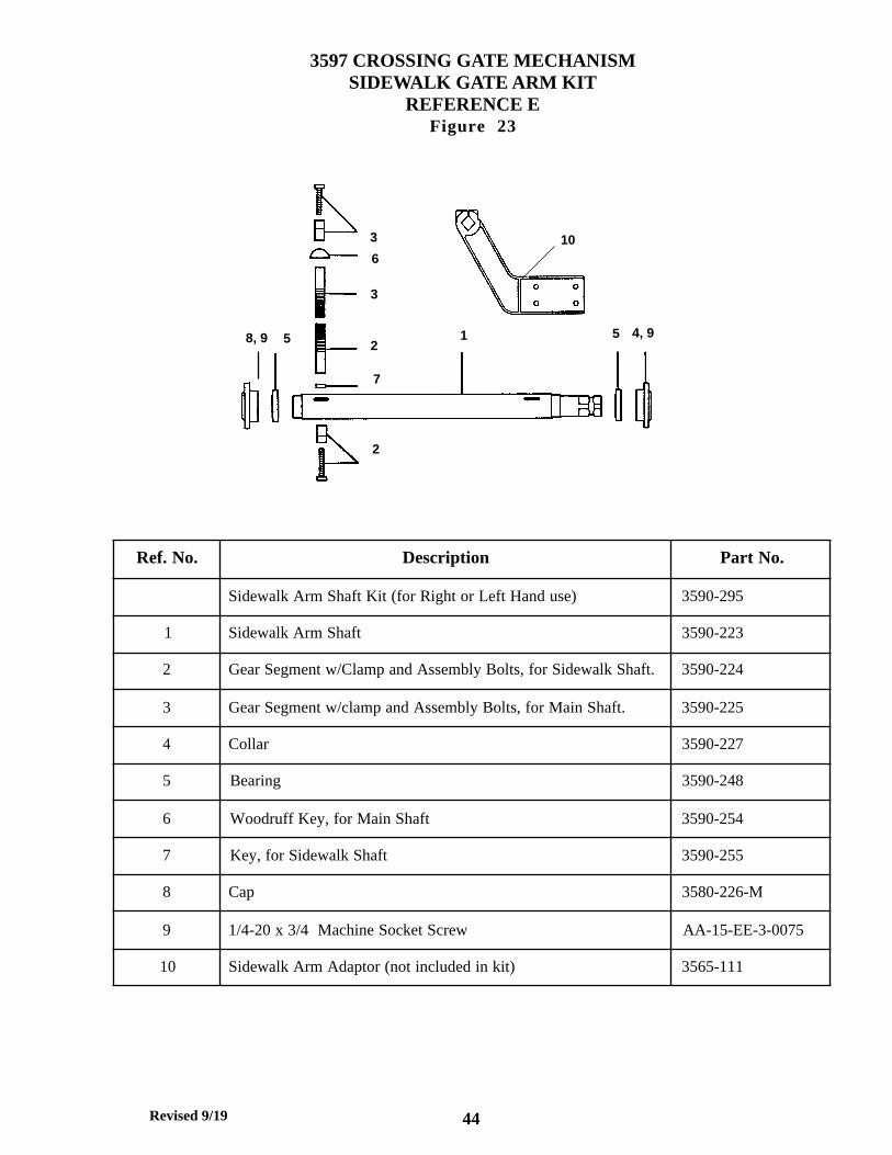
1. Sidewalk Arm Kit permits the addition of a sidewalk arm to the mechanismin service as operator of roadway arm. The kit includes necessary bearings,gears, keys, shafts and instructions. It does not include a sidewalk armbracket or a sidewalk arm (figure 23, page 44).
2. A heater may be attached to the mechanism for prevention of frost formationon controller contacts (figure 24, page 45).
3. Gate lamp fuse panel PN: 38-0045-540 (Figure 25, page 46).
4. Setup and adjustment tools are listed on the last page of the mechanismparts section.
Revised 9/19
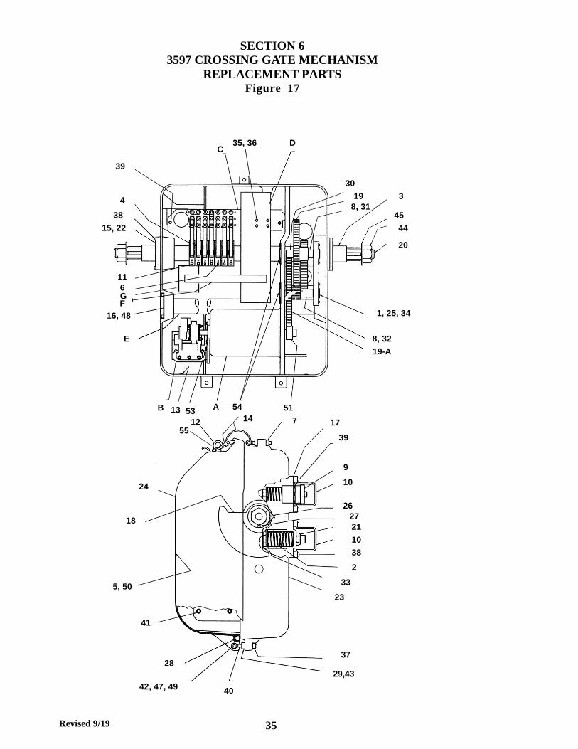
SECTION 63597 CROSSING GATE MECHANISM
REPLACEMENT PARTSFigure 17
39
CD
30
19 3
35, 36
45
20
44
515313B
E
F
6
54A
8, 31
16, 48 1, 25, 34
11
8, 32
19-A
4
38
15, 22
17
37
1412
40
24
18
39
7
9
10
26
2127
10
38
2
23
29,4328
41
5, 50
42, 47, 49
33
G
35
55

Revised 9/19
Ref. No. Description Part No.
1 Bearing Cover 38-0045-30
2 Spring, Vertical Stop 38-0045-38
3 Spacer Tube 38-0045-42
4 Cam Assembly 38-0045-55
5 Wiring Diagram 3597-WD-E
6 Slide Cam Assembly 38-0045-92
7 3/8"-16 Square Nut JJ-11-JJ-3
8 Gear Shaft for Intermediate Gears 38-0045-267
9 Horizontal Stop Pin Assembly 38-0045-305
10 Stop Pin Cover 38-0045-329-M
11 Cam Assembly 38-0045-536
12 Staple 1265-4
13 Ventilator Screen 1265-6-B
14 Hasp Assembly 1265-40-1
15 Main Shaft Bearing 3580-166
16 End Cap 3580-291
17 Neoprene Gasket 3580-281
18 Gear Segment 3590-219-F
19 Gear Cluster 3590-220-F
19-A Gear Cluster With Hole 3590-220-H
20 Main Shaft 3590-222
20-A Single End (Right) Main Shaft (Not Shown) 3590-226
21 Nut, Nylon Insert, for Vertical Stop Assembly 3590-231
22 Main Shaft Cap 3590-232
22-A Main Shaft Cap Without Hole (Not Shown) 3590-232-1
23 Case 3590-234-2-M
24 Cover 3590-240-2-M
25 Bearing 3590-249
3597 CROSSING GATE MECHANISMREPLACEMENT PARTS
Refer to Figure 17
36

Revised 9/19
3597 CROSSING GATE MECHANISMREPLACEMENT PARTS (CONTINUED)
Refer to Figure 17
37
.oN.feR noitpircseD .oNtraP
62 wercSteS 152-0953
72 yeKffurdooW 452-0953
82 teksaGrevoC 2-852-0953
92 rehsawkcoL"8/3 3-MA-00-RR
03 recapS 772-0953
13 recapS 872-0953
23 recapS 972-0953
33 ylbmessAniPpotSlacitreV 392-0953
43 wercSpaCtekcoSdaeHnottuB"8/3x23-8# 7300-3-BB-23-BB
53 wercSenihcaMdaeHdnuoR4/1-1x42-01# 5210-3-CC-01-AA
63 rehsaWkcoLtilpS01# 3-HA-00-RR
73 tuNkolyNxeH"8/3 3-JJ-21-LA
83 wercSpaCtekcoSdaeHxeH"4/3x02-"4/1 5700-3-EE-32-BB
93 wercSpaCtekcoSdaeHxeH"4/3x02-"4/1 5700-3-EE-32-BB
04 tlobeyE 183-0953
14 wercSpaCtekcoS"4/3x61-"8/3 5700-3-JJ-95-BB
24 tloBdaeHxeH"4/12x81-"61/5 5220-3-GG-21-CC
34 tuNxeH61-"8/3 3-JJ-21-KK
44 tuNxeH7-"4/1-1 3-DA-21-JJ
54 rehsaWtalFDI"4/1-1 411-0753
64 wercSenihcaMdaeHdnuoR"4/3-2x42-01 5720-3-CC-01-AA
74 rehsaWnialP"4/1 3-JA-00-PP
84 wercSpaCtekcoSxeH"8/3x02-"4/1 7300-3-EE-32-BB
94 kolyNxeH81-"61/5 3-GG-21-LA
05 launaMnoitallatsnI MI-7953
15 raeGnoiniP 22-7953
25 )nwohStoN(tsaM"5roftiKgnitnuoM 492-0953
35 wercSpaC 282-5400-83
45 paCgniraeBrofrecapS 572-0953
55 tiKgnirpSredloHhctaL KS-04-5621

Revised 9/19
3597-20 MOTOR ASSEMBLYREPLACEMENT PARTS
REFERENCE AFigure 18
910
11
8
4
3
1
2
5,6,712
Ref. No Description Part No.
Motor Assembly Complete 3597-20
1 Ratchet Wheel 38-0045-262
2 Ratchet Wheel Key 3580-270
3 Snap Ring 3580-271
4 Washer 38-0045-182
5 Motor Brush Cap 3597-20-12
6 Motor Brush 3597-20-13
7 Motor Brush Holder 3597-20-14
8 Motor 3597-20-1
9 Motor Pinnion Woodruff Key 3597-21
10 Washer 38-0045-241
11 8-32 x 1/2" Nylock Round Head Machine Screw BJ-10-BB-3-005
12 Motor Pinnion Gear 3597-22
38

Revised 9/19
20
17
24
26
23
27
8,3132,33
20
26
23
17
2,9
16
11, 12, 29, 30
24
1
14
19
7
34
5, 28
25 2122
13 1518
610
11, 12, 29, 30
38-0045-510 HOLD CLEAR ASSEMBLYREPLACEMENT PARTS
REFERENCE BFigure 19
39
Revised 9/19
38-0045-510 HOLD CLEAR ASSEMBLYREPLACEMENT PARTS
REFERENCE BRefer to Figure 19
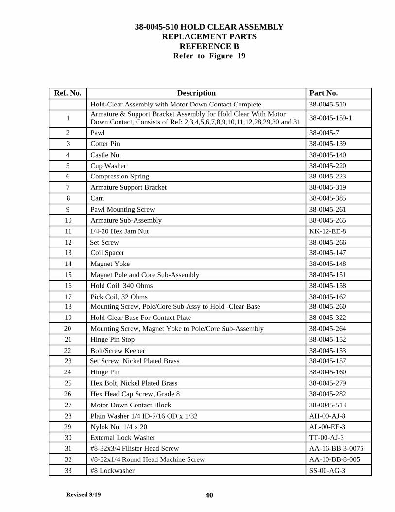
Ref. No. Description Part No.Hold-Clear Assembly with Motor Down Contact Complete 38-0045-510
1 Armature & Support Bracket Assembly for Hold Clear With MotorDown Contact, Consists of Ref: 2,3,4,5,6,7,8,9,10,11,12,28,29,30 and 31 38-0045-159-1
2 Pawl 38-0045-7
3 Cotter Pin 38-0045-139
4 Castle Nut 38-0045-140
5 Cup Washer 38-0045-220
6 Compression Spring 38-0045-223
7 Armature Support Bracket 38-0045-319
8 Cam 38-0045-385
9 Pawl Mounting Screw 38-0045-261
10 Armature Sub-Assembly 38-0045-265
11 1/4-20 Hex Jam Nut KK-12-EE-8
12 Set Screw 38-0045-266
13 Coil Spacer 38-0045-147
14 Magnet Yoke 38-0045-148
15 Magnet Pole and Core Sub-Assembly 38-0045-151
16 Hold Coil, 340 Ohms 38-0045-158
17 Pick Coil, 32 Ohms 38-0045-16218 Mounting Screw, Pole/Core Sub Assy to Hold -Clear Base 38-0045-260
19 Hold-Clear Base For Contact Plate 38-0045-322
20 Mounting Screw, Magnet Yoke to Pole/Core Sub-Assembly 38-0045-264
21 Hinge Pin Stop 38-0045-152
22 Bolt/Screw Keeper 38-0045-153
23 Set Screw, Nickel Plated Brass 38-0045-157
24 Hinge Pin 38-0045-160
25 Hex Bolt, Nickel Plated Brass 38-0045-279
26 Hex Head Cap Screw, Grade 8 38-0045-282
27 Motor Down Contact Block 38-0045-513
28 Plain Washer 1/4 ID-7/16 OD x 1/32 AH-00-AJ-8
29 Nylok Nut 1/4 x 20 AL-00-EE-3
30 External Lock Washer TT-00-AJ-3
31 #8-32x3/4 Filister Head Screw AA-16-BB-3-0075
32 #8-32x1/4 Round Head Machine Screw AA-10-BB-8-005
33 #8 Lockwasher SS-00-AG-3
40

Revised 9/19
38-0045-513 MOTOR DOWN CONTACT BLOCKREPLACEMENT PARTS
Figure 20
Ref. No Description Part No.
1 Contact Plate 38-0045-511
2 Washer Plate 38-0045-376
3 Keeper 38-0045-380
4 Mounting Block Spacer 38-0045-381
5 Spacer 38-0045-382
6 Insulator 38-0045-383
7 Screw 38-0045-384
8 Upper Contact Spring Assembly 38-0045-387
9 Lower Contact Spring Assembly 38-0045-388
10 Terminal Block 2507-6
11 #10-32 x 1/2 Round Head Machine Screw AA-10-DD-8-005
12 #10 Lockwasher External TT-00-AH-3
13 A.A.R. Clamp Nut 10707
14 Washer 10708
15 Diode Assembly 38-0045-512
16 Guard 38-0045-386
17 #8-32 x 1/4 Round Head Machine Screw AA-10-BB-8-0025
7
15
11, 12
17
16
5
2
8
9
64
1
3
14
1310
41
Revised 9/19
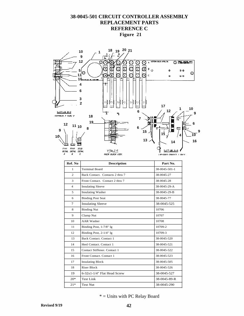
Ref. No Description Part No.
1 Terminal Board 38-0045-501-1
2 Back Contact. Contacts 2 thru 7 38-0045-27
3 Front Contact. Contact 2 thru 7 38-0045-28
4 Insulating Sleeve 38-0045-29-A
5 Insulating Washer 38-0045-29-B
6 Binding Post Seat 38-0045-77
7 Insulating Sleeve 38-0045-525
8 Binding Nut 10706
9 Clamp Nut 10707
10 AAR Washer 10708
11 Binding Post, 1-7/8" lg 10709-2
12 Binding Post, 2-1/4" lg 10709-3
13 Back Contact. Contact 1 38-0045-520
14 Heel Contact. Contact 1 38-0045-521
15 Contact Stiffener. Contact 1 38-0045-522
16 Front Contact. Contact 1 38-0045-523
17 Insulating Block 38-0045-505
18 Riser Block 38-0045-526
19 6-32x1-1/4" Flat Head Screw 38-0045-527
20* Test Link 38-0045-89-R
21* Test Nut 38-0045-290
38-0045-501 CIRCUIT CONTROLLER ASSEMBLYREPLACEMENT PARTS
REFERENCE C Figure 21
713
910
16
6
109
117
12
7
615
14
411
6
19
18
8101112
9
10
3
6
4
10115
129
10
2
18 19120 21
* = Units with PC Relay Board
42

Revised 9/19
3597-3 CONTROL ASSEMBLYREPLACEMENT PARTS
REFERENCE DFigure 22
.oN.feR noitpircseD rebmuNtraP
1 pmalCeriW B-21-3591
2 MPepyT,B&P,yaleR 21-45219
*2 draoByaleR 3-01-7953
3 revoCyaleR 1-45219
*3 esaB 2-01-7953
*A3 4FVepyT,B&P,yaleR 1-01-7953
etelpmoC*A3,3,2smetI 01-7953
5,4 rotsiseRmhO5.1 2-0111
6 rotinoMetaGcinortcelE 1-7953
7 lenaPyaleR 1-3-7953
8 pmalCeriW A-6-3591
9 etelpmoChctiwSmaC 2-7953
01 lenaPhctiwSmaC 2-3-7953
11 lebaLebuL 005-5400-83
21 bonKhctiwSmaC 1-2-7953
*= Units with PC Relay Board Replacement Parts Only
2*
3*
3A*
43
Revised 9/19
6
7
2
3
3
1 55
2
8, 9 4, 9
10
3597 CROSSING GATE MECHANISMSIDEWALK GATE ARM KIT
REFERENCE EFigure 23
Ref. No. Description Part No.
Sidewalk Arm Shaft Kit (for Right or Left Hand use) 3590-295
1 Sidewalk Arm Shaft 3590-223
2 Gear Segment w/Clamp and Assembly Bolts, for Sidewalk Shaft. 3590-224
3 Gear Segment w/clamp and Assembly Bolts, for Main Shaft. 3590-225
4 Collar 3590-227
5 Bearing 3590-248
6 Woodruff Key, for Main Shaft 3590-254
7 Key, for Sidewalk Shaft 3590-255
8 Cap 3580-226-M
9 1/4-20 x 3/4 Machine Socket Screw AA-15-EE-3-0075
10 Sidewalk Arm Adaptor (not included in kit) 3565-111
44

Revised 9/19
3597 CROSSING GATE MECHANISM CONTACT HEATER ASSEMBLY
REFERENCE FFigure 24
Ref. No. Description Part No.
F Contact Heater Assembly Complete, 115 VAC, 50 Watt, 500 Ohms 3597-4
F1 Contact Heater Assembly Complete, 24 VDC, 50 Watt, 25 Ohms 3597-5
F2 Contact Heater Assemmbly, 12 VDC, 50 Watt. 10 Ohms 3597-6
45

Revised 9/19
38-0045-540 GATE LAMP FUSE PANELREPLACEMENT PARTS
REFERENCE GFigure 25
Ref. No Description Part No.
1 Terminal Block 2507-6-1
2 Panel 38-0045-541
3 10 AMP Type ATC Fuse 400-35-50
4 Fuse Holder 50-0274
5 Crimp Terminal 31908-MT
46

Revised 9/19
Set-Up and Adjustment Tools
Spring Scale, PN: 3562-210Used for measuring gate arm torque.
Torque wrench with socket, PN: 3590-K-9.Used for measuring gate arm torque.
Snap ring pliers, PN: 3590-1007Used for ratchet wheel removal.
.020 gauge, PN: 3590-1012Used to adjust ratchet wheel to hold clear pawl clearance.
.032 gauge, PN: 3590-1011Used to adjust gap on hold clear mounted power down contact.
Ounce spring scale, PN: 3565-211Used to measure contact spring pressure.
1/16" insulated gauge, PN: 3590-1010
1/8" insulated gauge, PN: 3590-1015Used to check contact gap.
Contact bending tool for contacts without stiffeners, PN: ES-6104-2
Contact bending tool for contacts with stiffeners, PN: ES-6104-1Used to adjust circuit board contact.
Angle finder, PN: 3590-1014Used to set contact cam operating position.
3/32" wire gauge, PN: 3590-1013Used to check vertical stop to segment gear clearance.
Tool kit, PN: 3590-K-11Includes snap ring pliers, 3/32", 3/16" and 7/32" T handle allen wrenches, 7/16"combination wrench and canvas pouch.
Aeroshell 33 lubricating grease, PN: 3590-1733For lubrication of gears, 1 quart can.
47

Revised 9/19
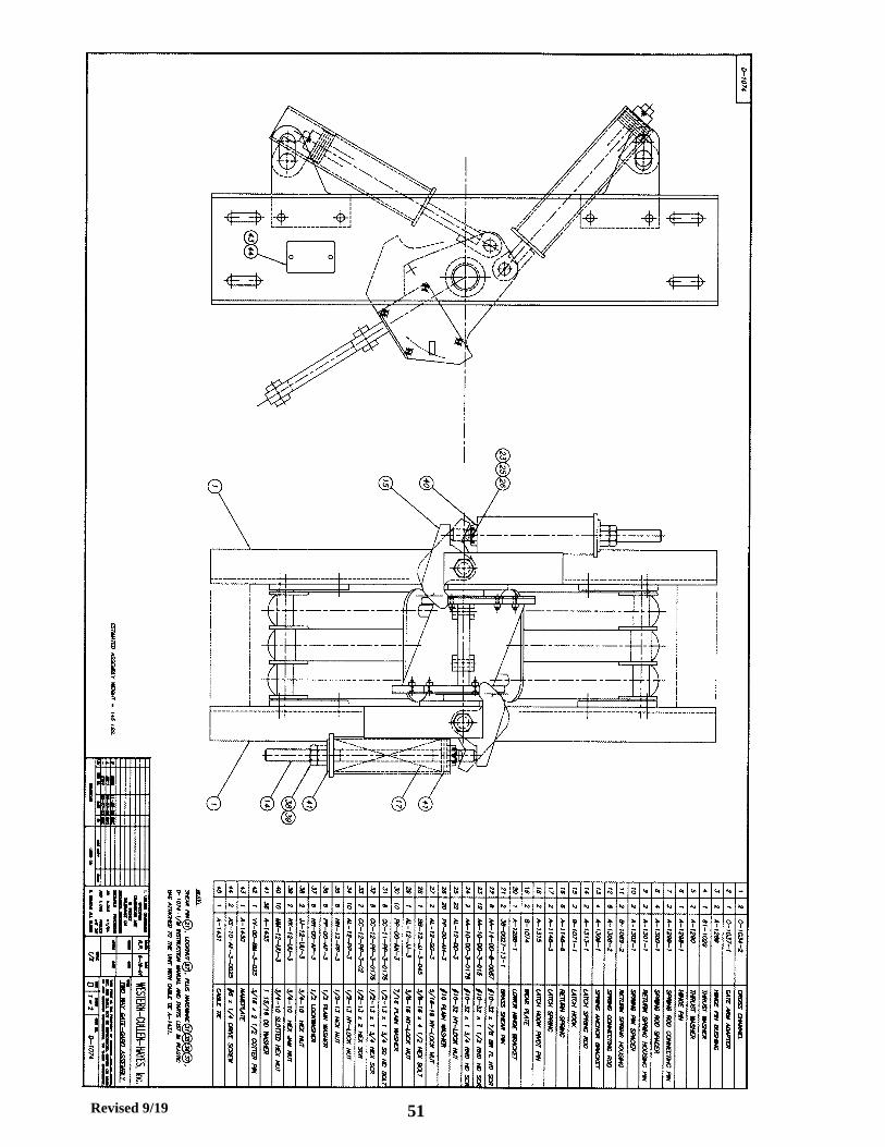
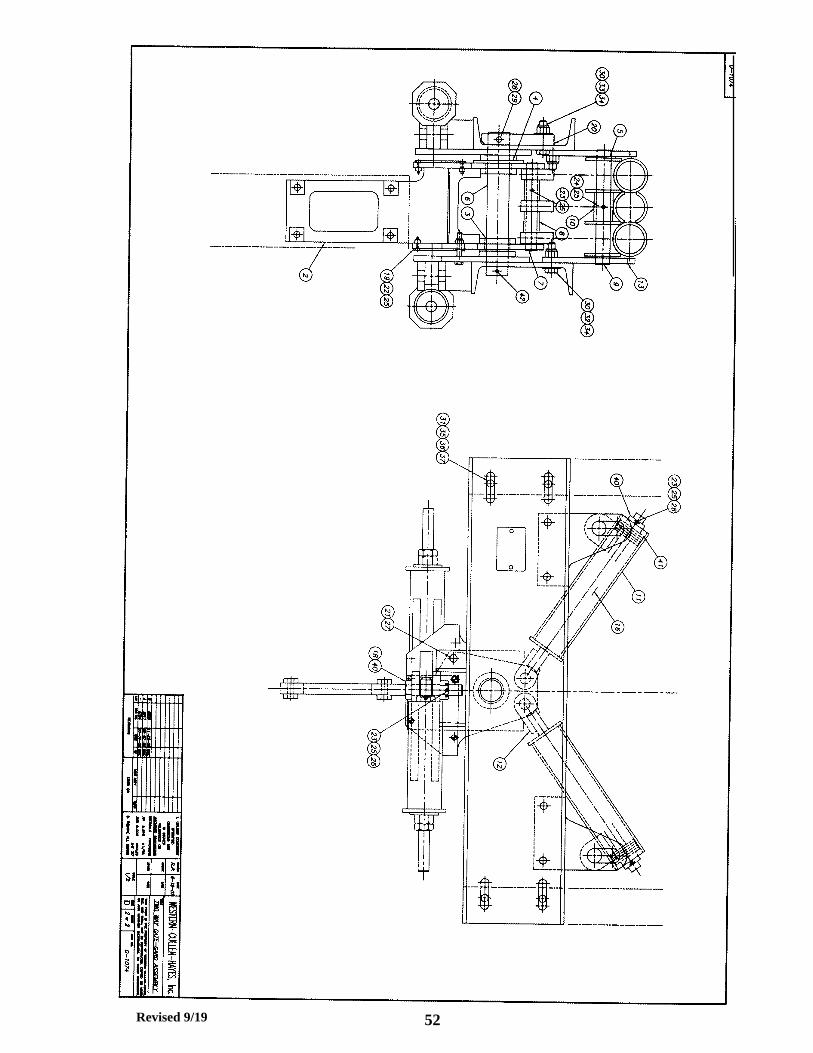
THE TWO-WAY GATE-GARDPart Number: D-1074
The TWO-WAY GATE-GARD is a device installed between a railroad grade crossing gatearm and the arm and the operating mechanism which allows the gate arm to rotate aboutan axis perpendicular to the gate arm length.
The purpose of the device is to minimize gate arm damage from wind pressure, vandalismor from contact with vehicles. The Gate Gard provides flexibility to the gate arm joint andallowing the lowered gate arm to rotate in a direction parallel with the roadway uponcontact with, or pressure to, either side of the gate arm.
The TWO-WAY GATE-GARD can be installed on new or in service Western-Cullen-Hayestype grade crossing systems without making alterations to the existing gate arm or itsoperating mechanism. Some counterweight adjustment may be necessary.
TWO-WAY GATE-GARD SPECIFICATIONS
Attaches to the counterweight support arms of any standard crossing gate mechanism,replacing the existing gate arm adapter and conversion bracket.
Incorporates a spring loaded mechanical latch system to lock the gate arm firmly in itsconventional position under normal operating conditions and allows the Latch Hook torelease when the gate arm rotating forces are applied.
Features a return spring system capable of bringing the longest gate arm back to theirnormal, locked position when the rotating force is relieved.
Has a drag brake, with a replaceable bronze wear plate, built into the latch hook system toretard the speed of the returning gate arm.
Includes brass pins with locknuts to provide additional resistance to gate arm rotation inhigh wind areas.
MAINTENANCE
The TWO-WAY GATE-GARD requires no lubrication or adjustments, It should, however,be inspected on a regular basis to ensure that there are no loose fasteners or broken partsdue to impact damage and to determine that the gate arm rotates and returns properly.
WEAR PLATE
Check the bronze Wear Plate (19) for excessive wear if the unit is in a high usage location.The Wear Plates can be replaced, if necessary, without removing the gate arm from GateArm Adapter (2) or removing the TWO-WAY GATE-GARD from the crossing gate mecha-nism. Rotate arm slightly for access to the front mounting screws.
RETURN SPRINGS
Springs (16) can be replaced, if necessary, without removing the gate arm from the GateArm Adapter (2) or removing the TWO-WAY GATE-GARD from the crossing gate mecha-nism.
Remove the lock screws and nuts at the end of the Return Spring Housing (11) and backoff the Slotted Nuts (40) to relieve the spring pre-load.
Remove the lock screw and nut from the Spring Pin Spacer (10) and remove the ReturnSpring Housing Pin (9). Rotate the Spring Housing (11) away from the counterweightsupport arms for spring removal clearance.
48

Revised 9/19
TWO-WAY GATE-GARD INSTALLATION INSTRUCTIONS
Part Number: D-1074
1. Lower the gate mechanism and crossing gate arm to the horizontal position and lockthe mechanism in place and/or block up the counterweight to prevent moving of thecounterweight support arms.
2. Remove the gate arm from the existing gate arm adapter and remove the existingadapter and conversion bracket from the counterweight support arms.
3. Slide the Two-Way Gate-Gard over the counterweight support arms. Apply a smallamount of anti-seize compound to the threads of the mounting bolts (31) and secure butdo not tighten. Remove the wood spacer blocks between the channels, tapping the lowerchannel to loosen if necessary.
4. Tighten the bolts securing the channels to the counterweight support arms.5. Re-install the existing gate arm to the Gate Arm Adapter (2).
6. Check the horizontal and vertical torque of the crossing gate mechanism per specifi-cations and re-adjust the counterweight positions if necessary.
7. Grasp the gate arm near the mid length point, rotate the arm 30 degrees or so andrelease. Repeat 3 or 4 times to allow the Latch Hook (15) to disengage from the GateArm Adapter (2) and to break-in the leading edge of bronze Wear Plate (19) Clean offany metallic particles that may accumulate during break-in. Repeat this process for theopposite direction of rotation.
8. Check for zero clearance between the end of the Latch Spring Rod (14) and the LatchHook (15). Adjust hex nut (38) and jam nut (39) at the bottom of Rod (18) if necessary,while maintaining the alignment of the gate arm and the mast.
9. Shear Pins (21) with lock nuts (27) can be installed through the Cross Channels (1)and the Gate Arm Adapter (2) to provide additional resistance to rotation in high windareas if necessary.
49

Revised 9/19
The Gate -Gard return spring systems designed to provide rotation resistance in highwind conditions and to provide adequate power to return a rotated gate arm of up toforty feet in length, to its normal position.
In some circumstances, when short gate arms are used, it may be desirable to reducethe return spring energy. This will slow the return speed of a rotated gate arm as wellas reduced the impact energy necessary to rotate the gate arm.
The Gate-Gard’s spring force can be reduced in any of three ways:
1. Reduce the number of washers, (41) at the end of each return spring housing tubes (11) from five to one. The Gate-Gard does not have to be removed from the crossing gate mechanism to do this modification. Simply remove the locking hardware (23), (25), (26) and back off the slotted nut (40). Remove all but one washer (41) and r e install nut (40) and locking hardware. This procedure will reduce the gate arm’s resistance to rotation from its normal position but will have minimal effect on the gate arm’s return speed.
2. Remove the middle return spring (16) from the Gate-Gard. Again, the Gate-Gard does not have to be taken off the gate mechanism to do this modification. Remove the nuts (40) and washers (41) from the six return springs assemblies as outlined in Step 1. Remove the locking hardware (24), (25) and remove the return spring hous- ing pin (9), spring pin spacer (10) and thrust washer (5). Next, swing the spring housing (11) away from the Gate-Gard and slide out the center spring (16). Thread a 3/4 - 10-jam nut, one washer (41) and slotted nut (40) onto the end of this center connecting rod (12) to keep it centered in the tube. Reposition the spring housing (11) and reinstall the housing pin (9) with spacer (10), washer (5) and locking hardware. Reinstall the five washers on each of the other four connecting rods (12) with nuts (40) and locking hardware.
Note that the washers must be below the end of each spring tube.
This step will reduce the gate arm’s resistance to rotation from the normal position andwill reduce the return speed from a rotated gate arm.
3. Steps one and two can be used together to achieve the exact combination of resis tance to rotation and gate arm return speed desired for a particular application.
Please contact Western-Cullen-Hayes with any questions you have regarding themodification of our Gate-Gard adapter.
50
Revised 9/19 51
Revised 9/19 52

Revised 9/19