textbook for vocational training - technology of metal
TRANSCRIPT

Textbook for Vocational Training − Technology of Metal Working − Part2

Table of ContentsTextbook for Vocational Training − Technology of Metal Working − Part 2................................................1
Preface...................................................................................................................................................15. Manufacturing Method of Separating..................................................................................................2
5.1. Dividing.....................................................................................................................................35.2. Chip−detaching.......................................................................................................................105.3. Erosion....................................................................................................................................94
6. Manufacturing Method of Joining....................................................................................................1026.1. Joining by Pressing On and In..............................................................................................1056.2. Joining by Initial Shaping......................................................................................................1206.3. Joining by Forming................................................................................................................1246.4. Joining by Uniting Substances..............................................................................................131
7. Manufacturing Method of Coating...................................................................................................1477.1. Coating with Solid Coating Substances................................................................................1497.2. Coating with Liquid Coating Substance................................................................................1527.3. Coating with Vapour−like or Gaseous Coating Substance...................................................1597.4. Coating with an Ionized Coating Substance.........................................................................161
8. Manufacturing Methods Changing the Properties of Materials.......................................................1668.1. Changing the Properties of Materials by a Rearrangement of Particles of Matter................167
9. Trends of Manufacturing Methods..................................................................................................1729.1. Initial Shaping........................................................................................................................1729.2. Forming.................................................................................................................................1739.3. Separating.............................................................................................................................1739.4. Joining...................................................................................................................................1749.5. Coating and Changing the Properties of Materials...............................................................174
i

ii

Textbook for Vocational Training − Technology of Metal Working − Part2
CRYSTAL
Lehr− und Lernmittel,Informationen, Beratung
Educational AidsLiterature, Consulting
Moyens didactiques,Informations, Service−conseil
Material didáctico,Informaciones, Asesoría
Feedback: IBE e.V.90−34−0107/2
Deutsche Gesellschaft fürTechnische Zusammenarbeit (GTZ) GmbH
Institut für berufliche Entwicklung e.V.Berlin
Original title:
"Technologie der Metallbearbietung − Teil 2"
Authors: Werner Kulke
Karl−Walter Finze
Rainer Hentschel
Volker Rempke
First edition © IBE
Institut für berufliche Entwicklung e.V.Parkstraße 2313187 Berlin
Order No.: 90−34−0107/2
Preface
The present textbook imparts knowledge of the technology of metal working. The manufacturing methods ofinitial shaping, forming, separating, joining, coating and changing the properties of materials are dealt with ingreat detail.
This textbook is intended for trainees in trades of the metalworking industry.
1
In a clearly arranged way, the means of work, the operations involved and the applications regarding theindividual manufacturing methods are described. A large number of comprehensive illustrations ensure thatthe subject−matters of the textbook can be grasped essily, that they are represented vividly and are closelyrelated to practice. The necessary expert knowledge of technological processes is imparted to the trainee sothat he will be in a position to tackle the problems involved unaided and in a creative manner.
The acquired knowledge will enable him to use the most important manufacturing methods in practice. Rulesto be kept in mind and summaries are given for focal points.
Information about work safety is marked by two vertical lines on the left margin of the text in question. Thequestions put at the end of the Chapters serve for checking the knowledge actually acquired.
5. Manufacturing Method of Separating
Keep in mind:
By separating, the shape of a workpiece is changed while the coherence of the material is neutralized at thepoint of separation.
The desired and actually achieved change in shape may be quite different:
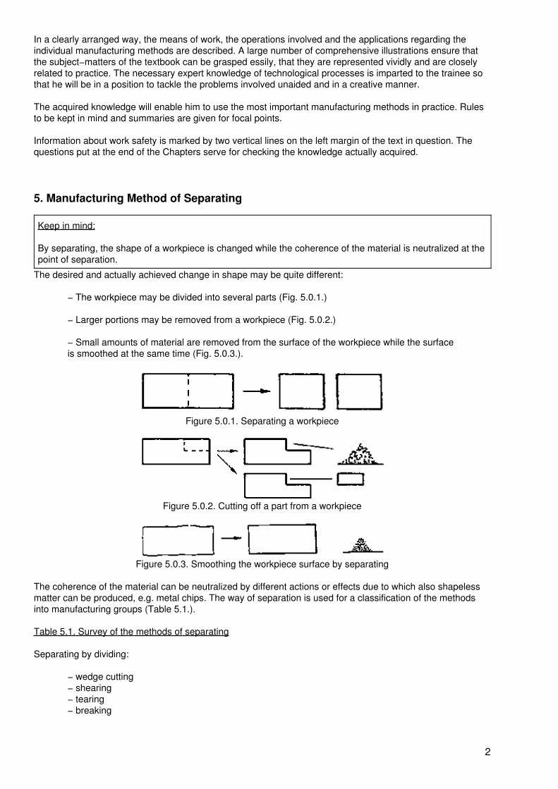
− The workpiece may be divided into several parts (Fig. 5.0.1.)
− Larger portions may be removed from a workpiece (Fig. 5.0.2.)
− Small amounts of material are removed from the surface of the workpiece while the surfaceis smoothed at the same time (Fig. 5.0.3.).
Figure 5.0.1. Separating a workpiece
Figure 5.0.2. Cutting off a part from a workpiece
Figure 5.0.3. Smoothing the workpiece surface by separating
The coherence of the material can be neutralized by different actions or effects due to which also shapelessmatter can be produced, e.g. metal chips. The way of separation is used for a classification of the methodsinto manufacturing groups (Table 5.1.).
Table 5.1. Survey of the methods of separating
Separating by dividing:
− wedge cutting− shearing− tearing− breaking
2

Separating by chip−detaching with geometrically defined cutting edges:
− turning− milling− planing, shaping− drilling, reaming, countersinking and counter−boring− sawing− reaming− scraping, filing− thread cutting
Separating by chip−detaching with geometrically undefined cutting edges:
− grinding− honing− lapping, polishing
Separating by removing particles of material by means of eroding and the like:
− eroding− elysing− etching− blasting− torch cutting
Separating by decomposition
Separating by cleaning
Separating by evacuating
5.1. Dividing
Dividing is defined as separating into two or more parts. Here, dividing is the heading of a group ofmanufacturing methods by which a workpiece is separated into two or more parts or parts of a workpiece aresevered without producing any shapeless matter.
Tool edges or tool surfaces act with high forces on the point of separation. In this process, limited shapingprocedures are involved and then, due to overloading the material, the coherence of the latter is neutralized −i.e. the material is divided.
5.1.1. Wedge Cutting
Cutting by means of wedges is a method that is widely used in various forms for cutting thin sections such aswire and for cutting out parts of thin plates of different materials.
Means of work
Nippers. A number of nippers of different size and design operates on the principle of wedge cutting (see alsoSection, 2.1., Figs. 2.1.15., 2.1.16. and 2.1.17.).
Hole−cutting chisels. In manually wedge cutting hole−cutting chisels are used in different sizes and withdifferent diameters (see Fig. 2.1.28.).
3

Pipe cutters. Pipe cutters are also hand tools (Fig. 5.1.1.). A pair of rotary cutting wheels is arranged in thepipe−cutter bow and a third wheel is arranged opposite to them in a vice. By means of a tommy screw, highforces can be applied to the cutting wheels via the spindle.
Cutting tools. Depending on the external contour of the workpieces to be cut out, the wedge−shaped ledgesare arranged on the tool (See Fig. 2.2.10.).
Figure 5.1.1. Pipe cutter
1 Cutting wheel,2 Movable vice,3 Bow,4 Threaded spindle,5 Tommy screw,6 Handle
Eccentric presses and crank−driven presses.Cutting tools are clamped in presses which carry out the desired cutting motions and provide the necessaryforces.
Procedure
The tool is applied to the position of separation with the wedge−shape cutting edge. Due to the forces actingon the wedge, it penetrates into the material. This leads to elastic deformations and plastic (i.e. permanent)deformations in the position of separation. When the wedge further penetrates into the material, high forcesact via the side surfaces of the wedge on the material. As a consequence, the remaining cross−section in theposition of separation is loaded so highly that the material breaks (Fig. 5.1.2.).
Figure 5.1.2. Principle of wedge cutting
1 Wedge,2 Workpiece,3 Deformations,4 Crack
4
A few of the means of work operate on two sides. In such tools, two wedges opposite to each other cut at thesame time.
Application
The narrow wedges of the tools produce a good separating effect but they do not possess a high stability.Therefore, wedge cutting can only be used for the separation of soft materials. The deformation occurring inthe position of separation is a disadvantage especially for metallic materials.
− Wires, braided wires and thin rods are cut by means of nippers.
− Cylindrical packing washers and packing rings are cut out of plates in small batches bymeans of hole−cutting chisels. Foils and thin sheets of soft metal, e.g. copper and aluminium,as well as rubber, leather and plastics can be pierced or punched by means of hole−cuttingchisels.
− In the installation and repair of pipe lines, thin−walled pipes for gas and water can be cut bymeans of pipe cutters.
− Larger batches of formed parts are cut out of foils, thin plates, rubber, plastics, asbestosand foil−coated paper and cardboard or provided with holes by means of cutting tools. In thisway, packings are produced and packing material is cut primarily.
Summary:
Wedge cutting is used to cut, punch and separate workpieces of thin and soft materials manually andmechanically. In the site of separation, deformations are produced especially in metallic materials.
5.1.2. Shearing
For the production of workpieces of sheet metal, shearing is the most frequently used and most versatilemethod of separating. In single−piece production it is performed manually and in large series and massproduction mechanically.
Means of work
Hand shears (see Fig. 2.1.20.).
Hand−lever shears (see Fig. 2.1.21.).
Plate shears. Plate shears for manual operation are available in various designs, i.e. with different lengths ofshearing and different permissible cutting thickness; machine shears operate on the principle of thecrank−driven press.
Roller shears. In plate shears, the possible shearing length is limited by the length of the shearing blades. Forlonger cutting lengths (over 3 to 5 m), roller shears must be used. The shearing blades take the form of rollersand are rotary (Fig. 5.1.3.). In shearing, the material to be cut is moved by the shearing rollers.
5

Figure 5.1.3. Principle of the roller shears
1 Plate,2 Shearing rollers,3 Point of shearing4 Gap of shearing
Shearing tools (see Figs. 2.2.12. and 2.2.13.).
Presses. For shearing by means of shearing tools, eccentric presses and crank−driven presses are primarilyused.
Procedure
The workpiece − mainly sheet metal − is placed between the shearing blades. In the shearing motion, thematerial is slightly upset and, consequently, elastically and plastically deformed. Due to the further action ofthe shearing blades, craks are produced in the shearing plane and the material is shorn off (Fig. 5.1.4.).
Figure 5.1.4. Procedure of shearing
1 Shearing jaws,2 Workpiece,3 Shearing force,4 Shearing motion,5 Gap of shearing
6

The shorn surface at the workpiece complies with low quality requirements only. The material in the shornsurface is only slightly deformed and a slight burr is produced. The quality of the shorn surface is largelyinfluenced by the size of the gap between the cutting edges, especially the formation of burr.
In shears which shear plates of different thicknesses and different materials, the gap between the cuttingedges must be set as desired. The following guide values are given:
− For soft materials: gap between cutting edges = 0.05 × plate thickness− for hard materials: gap between cutting edges = 0.1 × plate thickness
Obliquely ground shearing blades are not applied to the entire shearing length. As a consequence, themechanical force required is reduced by 40%. When shearing with oblique shearing blades (Fig. 5.1.5.), thedeformations produced in the workpieces are sometimes increased.
Figure 5.1.5. Shearing with oblique shearing blades
Application
By means of hand shears, machine shears and shearing tools, mainly workpieces of sheet metal areproduced. In addition, paper, cardboard and plastics of a low brittleness can be shorn. The shorn surfacesproduced must be refinished frequently.
Separation−shearing. Of plates or sheet−metal parts, pieces are shorn off with a straight cut, as a rule.Curved cuts are possible by means of hole−cutting shears. By means of roller shears, very long plates are cutinto strips and bands in rolling mills.
Shearing−out. By means of shearing tools, workpieces or blanks are shorn out of strips or sometimes ofplates on presses.
Holing. In this procedure, holes, frequently of intricate shape, are shorn out of workpieces. Frequently, holingand shearing−out are carried out together.
Workpieces of intricate shape are made on automatic shearing machines in small batches. By fine−shearing(i.e. holing and shearing−out together), shorn surfaces are obtained which comply with high qualityrequrements.
Holing and shearing−out are used for the production of:
− car−body parts, e.g. for motor−cars, panelling
− sheet blanks for containers and casings
− ironwork for furniture, doors and cases
7

− small parts for precision mechanics, e.g. washers, levers and gears, especially for officemachines and apparatuses.
Notching. In steel construction, various rolled steel sections are used. Mitres are notched (Fig. 5.1.6.) at thepoints of connection of sections or before bending. For this purpose, machine shears with special shearingblades or free shearing tools on presses are used.
Figure 5.1.6. Section with mitres
1 T−section,2 Notched mitres
Cutting−in. Cuts of different lengths are produced in sheet−metal parts by means of hand or machine shears.Usually, cutting−in is required for further bending operations (Fig. 5.1.7.).
Figure 5.1.7. Sheet−metal cut in before and after bending.
1 Sheet metal,2 Cut,3 Bent part of the workpiece
Trimming. Parts forged in dies have a burr that is produced at the plane where the two die parts meet.
The burr is shorn off from the workpieces by means of special deburring dies (Fig. 5.1.8.).
Parting. Simple enclosures of sheet metal can be assembled and joined together by lugs at the sheet−metalparts. In this way, special fasteners, e.g. screws, are not required.
The lugs are produced by three−side shearing and one−side bending by means of parting tools on presses(Fig. 5.1.9.).
8

Figure 5.1.8. Trimming a forging
1 Forged workpiece with burr,2 Shearing plate of the debarring die,3 Ram,4 Burr shorn off,5 Shearing area,6 Workpiece from which the burr has been removed
Figure 5.1.9. Example of parting
1 Ram,2 Workpiece,3 Shearing edges,4 Bending edges,5 Lugs, 6 Bottom die
Summary:
Shearing is used for the production of workpieces and sheet blanks. There are various methods of shearing.Massive workpieces are machined by shearing only in exceptional cases. Single pieces, small lots andmasses of products can be made manually and mechanically in an economical way. Special shearing toolsenable forming operations, e.g. bending, at the same time in addition to shearing. Apart from fine−shearing,the shorn surfaces obtained normally comply only with limited quality requirements and, thus, have to berefinished.
9

5.2. Chip−detaching
Keep in mind:
In chip−detaching, the shape of the workpiece is changed by the removal of material particles − the chips−by means of the wedge−shaped cutting edges on the tools.
In chip−detaching, certain motions or relative motions are involved which are carried out by the tool alone orby tool and workpiece (Fig. 5.2.1.). The following types of motion are necessary:
− starting motion− cutting motion− feed motion− in−feed motion− re−setting motion
Figure 5.2.1. Relative motions in chip−detaching
1 Tool,2 Workpiece,3 Starting motion,4 In−feed motion,5 Cutting motion,6 Feed motion,7 Effective motion
Starting motion. After the clamping of the workpiece and the tool, the starting motion is effected, this meansthat the tool is advanced and applied to the workpiece.
Cutting motion. Any chip−detaching machining method includes a typical cutting motion. The cutting motion −usually one revolution or one stroke − effects the detaching of a chip (or several chips) from the workpieceduring one motion.
Feed motion. Since the cutting motion detaches chips only once in this single motion, a further motion isrequired in order to continue cutting, this is the feed motion. Due to the usually straight feed motion, arepeated or continuous chip removal is ensured together with the cutting motion.
In−feed motion. The thickness of the layer of material to be removed from the workpiece is present by thein−feed motion. The in−feed motion is set before the removal of chips and is repeated after the individualoperations.
Re−setting motion. Due to various causes, e.g. wear of the tool cutting edge, the relative position of tool andworkpiece must be slightly changed from time to time. Such corrections are called re−setting motion.
10
Active motion. The cutting motion and the feed motion are subsumed under the heading of active motion. Theactive motion characterizes the motion of the cutting edge removing chips and the uninterrupted removal ofchips.
In order to cut economically, cutting motion and feed motion must be of optimum magnitudes. If the relativemotions between tool and work are too quick, the cutting edge of the tool will be overloaded and destroyedwhile the workpiece will also be impaired. When the relative motions are too slow, the load on the cutting edgewill be lower, however, the manufacturing time will become too long.
Cutting speed. The magnitude of the cutting motion is the cutting speed ?. For the majority of the
chip−detaching methods it is expressed in (metres per minute), for grinding in (metres per second).The tool manufacturers specify the most favourable cutting speeds for the tools produced by them which arealso compiled in Tables.
The optimum cutting speed is dependent upon
− the method− the material of the workpiece− the material of the cutting edge of the tool− the required surface quality of the workpiece− the cutting conditions, e.g. machine performance, cooling, course of cutting.
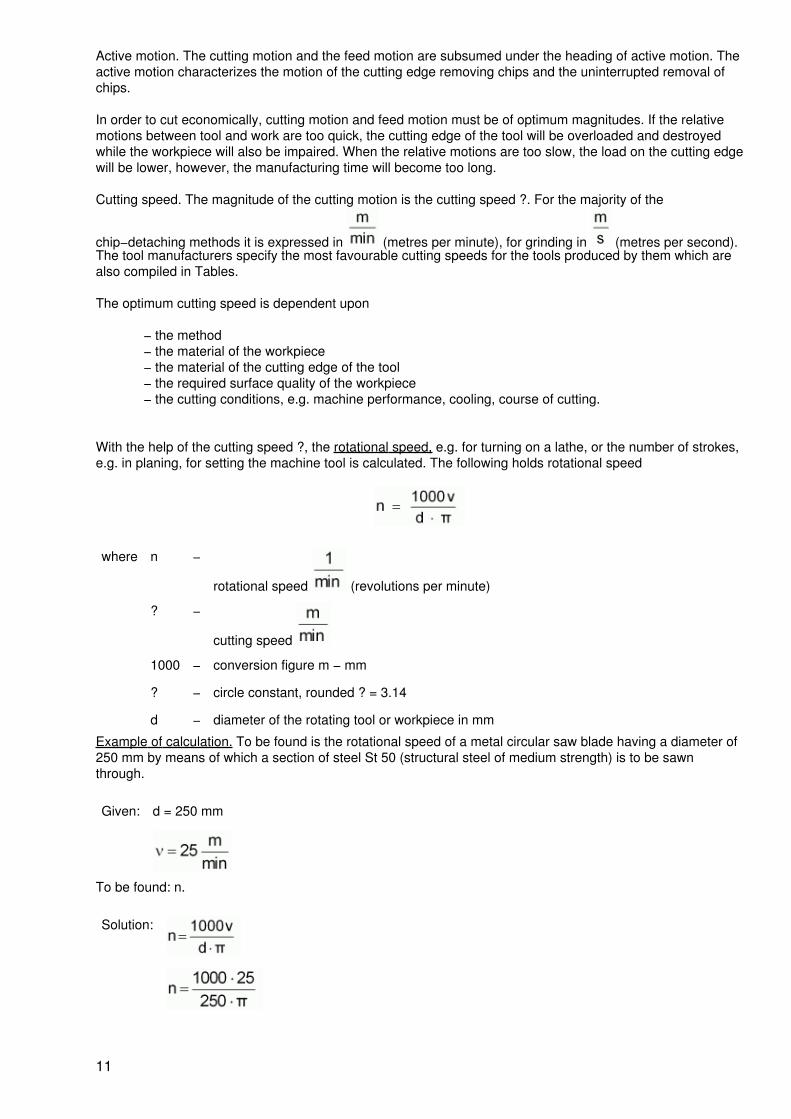
With the help of the cutting speed ?, the rotational speed, e.g. for turning on a lathe, or the number of strokes,e.g. in planing, for setting the machine tool is calculated. The following holds rotational speed
where n −
rotational speed (revolutions per minute)
? −
cutting speed
1000 − conversion figure m − mm
? − circle constant, rounded ? = 3.14
d − diameter of the rotating tool or workpiece in mm
Example of calculation. To be found is the rotational speed of a metal circular saw blade having a diameter of250 mm by means of which a section of steel St 50 (structural steel of medium strength) is to be sawnthrough.
Given: d = 250 mm
To be found: n.
Solution:
11

The rotational speed to be set at the machine for sawing is .
Mostly, the calculated speed cannot be set accurately at the machine because a certain group of speeds canonly be set. In this case, the next lower speed is set.
The magnitude of the feed motion is expressed differently.
Feed. For single−edged and, sometimes, for multi−edged tools, the feed s is stated in mm and set at themachine tools. The stated feed is always related to one revolution or one stroke. If, for example, drilling isperformed with a feed of s = 0.2 mm, the drill moves by 0.2 mm with each revolution in the feed direction.
Rate of feed. For technological calculations, the speed of the tool in feed direction is determined.
The rate of feed u in can be set on a few machines only.
For calculating, the following holds rate of feed
where s − feed in mm
n −
rotational speed in Example of calculation. What is the rate of feed reached by a twist drill which drills copper at a rotational
speed of and a feed s = 0.2 mm?
Given: s = 0.2 mm
To be found: u.
Solution:
The rate of feed of the twist drill is .
This means that the twist drill can produce a hole having a depth of 120 mm in one minute.
The material of the workpiece offers a resistance to the cutting motion, the feed motion and the in−feedmotion which manifests itself in the form of various forces. The following forces become effective.
− against the cutting motion − the cutting force− against the feed motion − the feed force− against the in−feed motion − the thrust force (Fig. 5.2.2.).
12

Figure 5.2.2. Forces involved in the chip−detaching procedure
1 Tool,2 Workpiece,3 Cutting motion,4 Feed motion,5 In−feed motion,6 Cutting force,7 Thrust force,8 Feed force,9 Cutting force
The three forces − cutting force, feed force and thrust force − are subsumed under the heading of thechip−removing force.
The chip−removing force acts on the tool and − with the same magnitude but in opposite direction − on theworkpiece.
Keep in mind:
The high chip−removing forces must be safely cushioned by correctly clamping tools and workpieces. Anynegligence leads to the destruction of the tool or of the workpiece and is a great danger of accidents.
Chip. In machining, particles of material are detached from the workpiece − the chips. In the course of themachining process, three phases of chip formation can be distinguished which, in practice, merge into eachother continuously and are repeated again and again (Fig. 5.2.3.).
Figure 5.2.3. Formation of chip
13
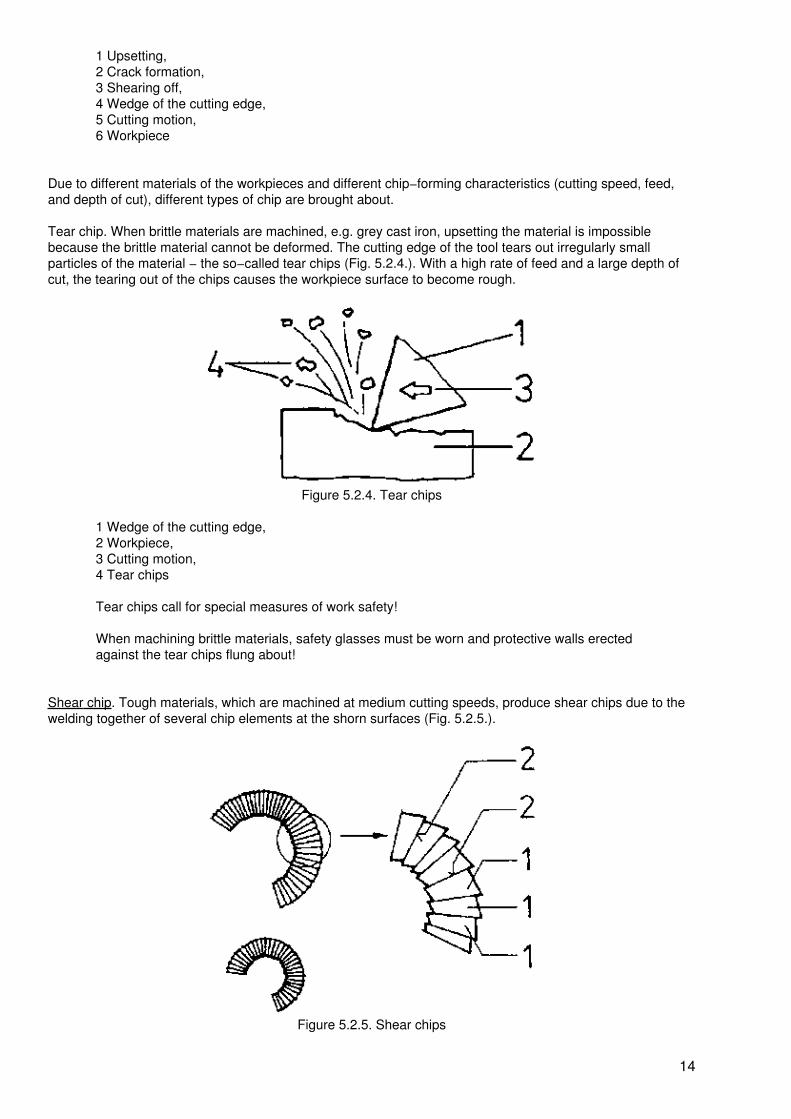
1 Upsetting,2 Crack formation,3 Shearing off,4 Wedge of the cutting edge,5 Cutting motion,6 Workpiece
Due to different materials of the workpieces and different chip−forming characteristics (cutting speed, feed,and depth of cut), different types of chip are brought about.
Tear chip. When brittle materials are machined, e.g. grey cast iron, upsetting the material is impossiblebecause the brittle material cannot be deformed. The cutting edge of the tool tears out irregularly smallparticles of the material − the so−called tear chips (Fig. 5.2.4.). With a high rate of feed and a large depth ofcut, the tearing out of the chips causes the workpiece surface to become rough.
Figure 5.2.4. Tear chips
1 Wedge of the cutting edge,2 Workpiece,3 Cutting motion,4 Tear chips
Tear chips call for special measures of work safety!
When machining brittle materials, safety glasses must be worn and protective walls erectedagainst the tear chips flung about!
Shear chip. Tough materials, which are machined at medium cutting speeds, produce shear chips due to thewelding together of several chip elements at the shorn surfaces (Fig. 5.2.5.).
Figure 5.2.5. Shear chips
14

1 Chip elements,2 Welded shearing surfaces
Flow chip. Mainly in turning soft and tough materials at high cutting speeds, very long flow chips are produceddue to the welding together of large numbers of chip elements (Fig. 5.2.6.).
Figure 5.2.6. Flow chips
Flow chips are dangerous due to their length and the high cutting speed involved! They mustbe deflected from the point of chip production by chip hooks. The attachment of chip breakersis advisible. Chip breakers are plates attached to the tool holder where the flow chip will strikeon and break.
5.2.1. Turning
Turning is a chip−detaching method of manufacturing with rotary cutting motion which is performed by theworkpiece. The feed motion, performed by the tool, usually is straight.
In turning rotationally symmetrical workpieces (Fig. 5.2.7.) are machined on their external surfaces (= turningexternal surfaces) and internal surfaces (= turning internal surfaces). As blanks, cast or forged workpieces areused. Frequently, rolled, extruded or drawn sections are further machined by turning on a lathe.
Figure 5.2.7. Parts to be turned
By turning, the following is achieved:
− a completely new shape of the workpiece,− finish−machined surfaces of the workpiece (in exceptional cases superfinishing)− a high accuracy to shape,
15

− small dimensional tolerances (in general 0.05 mm and smaller).
Means of work
Turning tool. Depending on the desired operation, different turning tool shapes are used. For a number ofturning tool shapes, a distinction is made between "left−hand" and "right−hand" turning tools is made. For thispurpose, the tool is places with the top face on top and the head in the direction of the observer. The positionof the main cutting edge − to the right or left − is decisive in this determination. Fig. 5.2.8. gives a survey ofthe most important cutting head shapes with examples of use.
Figure 5.2.8. Shapes of turning tools
1 Straight turning tool,2 Bent turning tool,3 Pointed turning tool,4 Wide turning tool,5 Offset facing tool,6 Offset side turning tool,7 End−cutting turning tool,8 Offset corner turning tool,9 Internal corner turning tool,10 Internal turning tool
An important factor of the proper operation of a turning tool is the corect tool geometry − the arrangement ofthe edges, surfaces and angles at the turning tool head (Fig. 5.2.9.).
The already known tool angles are also found at the turning tool. By grinding, the angle of relief ? and the rakeangle ?, cutting−wedge angle ? is obtained. The tool angles are measured at right angles to the main cuttingedge (Fig. 5.2.10.).
16
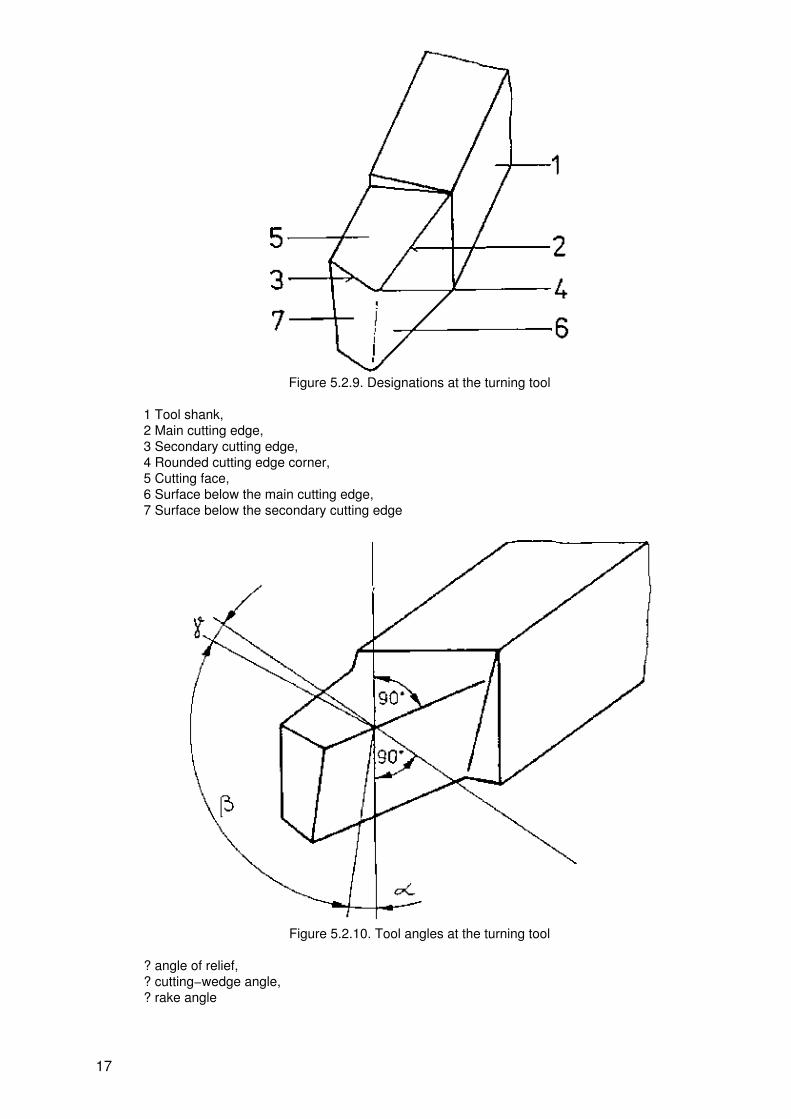
Figure 5.2.9. Designations at the turning tool
1 Tool shank,2 Main cutting edge,3 Secondary cutting edge,4 Rounded cutting edge corner,5 Cutting face,6 Surface below the main cutting edge,7 Surface below the secondary cutting edge
Figure 5.2.10. Tool angles at the turning tool
? angle of relief,? cutting−wedge angle,? rake angle
17

The magnitude of the tool angles is dependent on the material of the tool cutting−edge and of the workpiece.Usually, the angle of relief ? is 8° and the rake angle ? is between 8° and 20° when the cutting edges are ofhigh−speed steel. In cutting edges of cemented carbide, the relief angle ? is 5° and the rake angle ? between2° and 14°.
The angles ground at the turning tool must be observed when clamping the tool on the machine, that is to say,the tool must point at the centre of the workpiece (Fig. 5.2.11.).
Figure 5.2.11. Turning tool to be set to the centre of the workpiece
When the turning tool is clamped so that it points above the centre of the workpiece, the magnitude of theangle of relief ? is reduced. This leads to the fact that the surface below the cutting edge of the turning tool isapplied to the workpiece and hampers the machining operation. The cutting edge will be destroyed within ashort time and the surface of the workpiece damaged by the surface below the cutting edge of the toolcontacting the workpiece.
When the turning tool is clamped so that it points below the centre of the workpiece, the magnitude of the rakeangle ? is reduced. This impairs the cutting efficiency of the turning tool. When the rake angle ? = 0°, or evennegative, due to the position below the centre of the workpiece, the tool will scrape. The chip−removing forceinvolved will become very high and the cutting edge will be heated to a high temperature. The consequencesare rapid wear or destruction.
Keep in mind:
Turning tools must be adjusted to the centre of the workpiece and clamped in this position. Clamping theturning tool so that it points above or below the centre of the workpiece leads to changes in the tool anglesand impairs the machining operation.
Apart from the above mentioned tool angles, special angles are observed at turning tools which are ofparticular importance to the machining operation.
Angle of inclination ? (lambda). Between an (imaginary) horizontal and the main cutting edge, the angle ofinclination ? is measured. In general, the cutting edge of the turning tool is located horizontally, the angle ofinclination ? = 0° (Fig. 5.2.12.).
18

Figure 5.2.12. Turning tool with ? = 0°
1 Main cutting edge,2 Horizontal
For roughing (rough−machining on a lathe), the inclination angle ? is ground positive. The cutting edge dropstowards the corner of the cutting edge. As a consequence, the load on the cutting edge can be increased andthe chip flow is more favourable (Fig. 5.2.13.).
Figure 5.2.13. Turning tool with a positive angle of inclination ?
1 Main cutting edge,2 Horizontal
In general, the angle of inclination is 5°; for machining surfaces of castings, i.e. steel castings and greycast−iron, this angle is 30°.
Corner angle ? (epsilon). Between the main cutting edge and the secondary cutting edge, the corner angle ?is formed. It should be selected in such a way that a good dissipation of heat from the cutting edge is ensured.In pointed turning tools, the corner angle ? = 30° (Fig. 5.2.14.).
19

Figure 5.2.14. Corner angle ? at the turning tool
Keep in mind:
The following angles are ground on a turning tool:
− the angle of relief ?− the rake angle ?− the angle of inclination ?− the corner angle ? with the rounded corner.
The magnitude of the angles is decisive for a good chip removal and for the durability of the turning anglecutting edge.
Plan angle ? (kappa). Due to different setting and clamping of a turning tool in the tool holder, different planangles ? are obtained between the main cutting edge and the workpiece surface. The position of the cuttingedge exerts a considerable influence on the direction of the chip−removing force, especially the thrust force.
With a large plan angle ?, only a short part of the cutting edge is in engagement. Consequently, the load onthe cutting edge is high and the heat dissipation is unfavourable. The force action on the workpiece isfavourable in longitudinal direction; the cut is smooth and ensures fine surfaces (Fig. 5.2.15.).
20

Figure 5.2.15. Large plan angle ? of a turning tool
With a small plan angle ?, a long part of the cutting edge is in engagement − the load on the cutting edge isreduced, the heat dissipation from the cutting edge is good and the chips are properly carried off. The forceaction is unfavourable − workpieces with small diameters and larger lengths are subjected to deflections andvibrations (Fig. 5.2.16.).
Figure 5.2.16. Small plan angle ? of a turning tool
Designs of turning tools
Different cutting edge
materials call for different designs of turning tools. Turning tools of tool steel aredimensionally standardized square and rectangular
sectional steel bars; their head with the desired angles is produced by grinding.
21
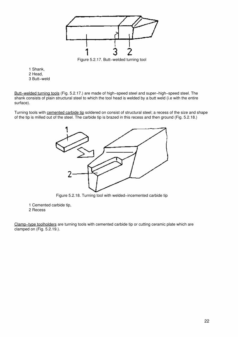
Figure 5.2.17. Butt−welded turning tool
1 Shank,2 Head,3 Butt−weld
Butt−welded turning tools (Fig. 5.2.17.) are made of high−speed steel and super−high−speed steel. Theshank consists of plain structural steel to which the tool head is welded by a butt weld (i.e with the entiresurface).
Turning tools with cemented carbide tip soldered on consist of structural steel; a recess of the size and shapeof the tip is milled out of the steel. The carbide tip is brazed in this recess and then ground (Fig. 5.2.18.)
Figure 5.2.18. Turning tool with welded−incemented carbide tip
1 Cemented carbide tip,2 Recess
Clamp−type toolholders are turning tools with cemented carbide tip or cutting ceramic plate which areclamped on (Fig. 5.2.19.).
22

Figure 5.2.19. Clamp−type holder with exchangeable cemented carbide tips
1 Clamp−type holder,2 Cemented carbide tip
Form turning tools. For turning special shapes, e.g. radii, form turning tools are used. Simple forming tools oftool steel are ground in such a way that the cutting edge shows the form which is desired in the workpiece(Fig. 5.2.20.).
Figure 5.2.20. Form turning tool of tool steel
Thread chasers are multi−edged tools for turning threads (see also Fig. 2.2.36.).
Lathes. In order to take advantage of the production of workpieces by turning, lathes of different designs andsizes are built and used.
Sliding and screw−cutting lathes (see also Fig. 2.4.16.) are built for workpieces having a diameter of up to1,300 mm and a length of up to 6,000 mm and are available in different sizes. Very heavy workpieces (up to70 t) with a diameter of up to 1,500 mm and a length of up to 7,000 mm are machined on very compact rollturning lathes.
For short workpieces with diameters of up to 4,000 mm, face lathes are employed. For the tooling of heavyparts with large diameters (up to 8,000 mm) and great lengths (up to 4,000 mm), various large designs ofvertical boring and turning mills are used. The workpiece is mounted and fastened on the table of the verticalboring and turning mill which is horizontally arranged and rotates during the machining operation.
Automatic screw machines do not call for continuous attendance but only for supervision. The automaticcarries out the individual operations independently.
Turret lathes accomodate several tools and enable a quick change of tools so that resetting is simplified.According to the design of the tool clamping devices, a distinction is made between horizontal turret (Fig.5.2.21.) and vertical turret (Fig. 5.2.22.). Tool changing is effected by turning the turret.
23

Figure 5.2.21. Horizontal turret
1 Tool holders,2 Clamped tools
Figure 5.2.22. Vertical turret
1 Tool holders,2 Clamped tools
Copying lathes trace a template or a workpiece prepared with great care − the so−called master −andtransmit the tracing motions exactly to the turning tool which turns the workpiece according to the tracingmotions. The attendance of the operator is reduced to the mounting and removing of the workpiece and thegeneral supervision. Clamping tools. Lathes are provided with different clamping tools for tools andworkpieces which are employed according to the production order. The turning tools are clamped in simpletool posts (Fig. 2.2.22.), turret heads (Figs. 5.2.21. and 5.2.22.) and special multiple holders. Other tools,which are also used on lathes, are accomodated with drill chucks (Fig. 2.3.10.) or retaining cones in a tailstock(see also Fig. 2.4.16.).
The workpieces usually are clamped in a three−jaw chuck (Fig. 2.3.8.). In addition, two−jaw chucks andfour−jaw chucks are used. Faceplates (Fig. 2.3.21.) are used to hold workpieces with non−circular intricateshapes.
Centres of different designs are used either on one side and the three−jaw chuck on the other side or on bothsides together with a driver for clamping work (Fig. 2.3.15.).
Special clamping devices for lathes are steady rests (Fig. 5.2.23.).
In case of long workpieces, they prevent the deflection during clamping cuased by the stresses involved,especially by the thrust force.
24

Figure 5.2.23. Steady rest
1 Lathe bed,2 Workpiece,3 Steady rest,4 Mounting of the steady rest,5 Sliding finger
Procedure
In turning, the workpiece is held by the workpiece clamping devices and performs the rotary cutting motion.From this fact, the term of the method, turning, is derived.
Turning can be grouped in three basic types of this machining method due to:
− the turning tools used− the direction of the in−feed motion− the direction of the feed motion
Plain or cylindrical turning. For turning cylindrical surfaces, the feed motion is performed manually ormechanically along the workpiece axis. The in−feed movement is performed towards the workpiece axis andis equal to the depth of cut (Fig. 5.2.24.).
The in−feed movement and the subsequent chip−removal change the diameter of the workpiece.
25

Figure 5.2.24. Plain or cylindrical turning
1 Workpiece,2 Turning tool,3 Starting motion,4 In−feed motion,5 Cutting motion,6 Feed motion,7 Depth of cut,8 Initial diameter,9 Turned diameter
Surfacing. The turning of plane surfaces on workpieces of any shape is effected by a feed motion in thedirection of the workpiece axis and an in−feed movement along the workpiece axis (Fig, 5.2.25.). In surfacing,the workpieces become shorter.
26

Figure 5.2.25. Surfacing
1 Workpiece,2 Turning tool,3 Starting motion4 In−feed motion,5 Cutting motion,6 Feed motion,7 Depth of cut,8 Initial length,9 Turned length
Plunge−cut turning. As in surfacing, the feed motion is carried out in the direction of the workpiece axis. Dueto the use of special tools, the in−feed motion is omitted (Fig. 5.2.26.).
27
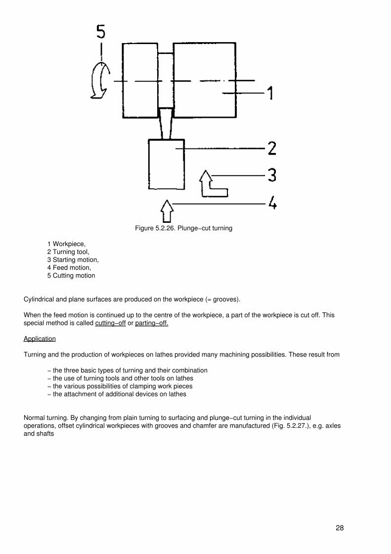
Figure 5.2.26. Plunge−cut turning
1 Workpiece,2 Turning tool,3 Starting motion,4 Feed motion,5 Cutting motion
Cylindrical and plane surfaces are produced on the workpiece (= grooves).
When the feed motion is continued up to the centre of the workpiece, a part of the workpiece is cut off. Thisspecial method is called cutting−off or parting−off.
Application
Turning and the production of workpieces on lathes provided many machining possibilities. These result from
− the three basic types of turning and their combination− the use of turning tools and other tools on lathes− the various possibilities of clamping work pieces− the attachment of additional devices on lathes
Normal turning. By changing from plain turning to surfacing and plunge−cut turning in the individualoperations, offset cylindrical workpieces with grooves and chamfer are manufactured (Fig. 5.2.27.), e.g. axlesand shafts
28

Figure 5.2.27. Example of production by normal turning
When normal turning is performed in the form of turning internal and external surfaces, workpieces withcylindrical and offset cylindrical cavities can be produced (Fig. 5.2.28.), e.g. bushings and casings.
Figure 5.2.28. Example of production by internal turning
Form turning. By means of form turning tools, details are turned in workpieces internally and externally, e.g.radii, grooves (Fig. 5.2.29.).
29

Figure 5.2.29. Form turning
In the case of smaller workpieces, the entire external shape can be produced by means of a form turning tool.In single−piece production, the experienced turner produces the shape manually, observing longitudinal feedand cross feed at the same time.
Turning off centre (also known as eccentric turning). When clamping the workpiece eccentrically, eccentrics,e.g. eccentric disks, can be turned on a lathe by the methods of plain turning and surfacing. After pre−turning,the workpiece is placed eccentrically between centres and machines (Fig. 5.2.30.).
Crankpin lathes, as special−purpose machines, have tool clamping devices which enable a precise eccentricposition of the workpiece. The pins of crankshafts, e.g. for motor−car engines, crank−driven presses andcompressors, are machined individually by normal turning after the necessary setting operation.
Figure 5.2.30. Turning off centre
1 Pre−turning,2 Clamping the workpiece eccentrically,3 Turning off centre (also known as eccentric turning),4 Finished workpiece
Taper turning. For turning taper workpieces or conical sections of workpieces, three different toolingpossibilities are given on lathes depending on the dimensions of the taper. The necessary setting quantitiesare calculated on the basis of the dimensions of the taper to be produced (Fig. 5.2.31.).
30

Figure 5.2.31. Dimensions and quantities of the taper
1 Large taper diameter,2 Small taper diameter,3 Initial length of the workpiece,4 Taper length,
5 Taper 1:k, ? Taper angle, Setting angle
The taper ratio 1:k is very important for the standardization of sealing and retaining cones. The taper ratio 1:kindicates that, over a length of k millimetres, the diameter of the taper is increased or reduced by onemillimetre. For example, taper pins have a taper ratio 1:I< = 1:50. This means that, over a length of 50 mm,the diameter of the taper pin is increased or reduced by one millimetre. For technical representations, thetaper ratio 1:k must be stated. It can be calculated from the dimensions of the taper. It holds
where l = length of the taper
D = major taper diameter
d = minor taper diameter
Example: What is the taper ratio of 1:k of a cone having a length of 60 mm, a major diameter of D = 30 mmand a minor diameter of d = 26 mm?
Given: l = 60 mm
D = 30 mm
d = 26 mm
To be found: 1:k
Solution:
k = 15 this results in 1:k = 1:15
The taper ratio to be found is 1:k = 1:15.
31

Taper turning with upper slide adjustment. For turning short internal and external tapers, the upper slide of the
lathe with tool post is adjusted by the setting angle (plan angle) (Fig. 5.2.32.).
Figure 5.2.32. Taper turning with adjustment of the upper slide (or tool rest)
1 Taper workpiece,2 Cutting motion,3 Feed motion,4 Crank for the feed motion,5 Upper slide,6 Scale in degrees,7 Turning tool,
Setting angle
When the feed motion is perfformed manually at the upper slide, the taper is produced in machining. Thelength of tapers to be produced is limited by the length of the upper slide and the turning tool motiondepending on this length.
Taper turning with former plate. The former plate is an additional device which can be attached to sliding andscrew cutting lathes. The former plate is set obliquely for the plan angle and, with mechanical feed, guides thetool slide (Fig. 5.2.33.).
32

Figure 5. 2.33. Taper turning with former plate
1 Former plate,2 Longitudinal groove as guide,3 Guide piece,4 Connection between guide piece and former plate,5 Scale in degrees,6 Cross slide,7 Feed motion,8 Cutting motion,9 Taper workpiece,10 Tailstock,11 Lathe bed,12 Tool holder,
Setting angle
The maximum taper ratio is 1:k = 1:5. The length that can be turned depends on the length of the former platefor external tapers and, for internal tapers, it is limited by the length of the shank of the turning tool.
Taper turning with tailstock adjustment. For turning long and slender external tapers, the tailstock and, thus,the centre is laterally adjusted (Fig. 5.2.34.).
Figure 5.2.34. Taper turning with tailstock adjustment
33
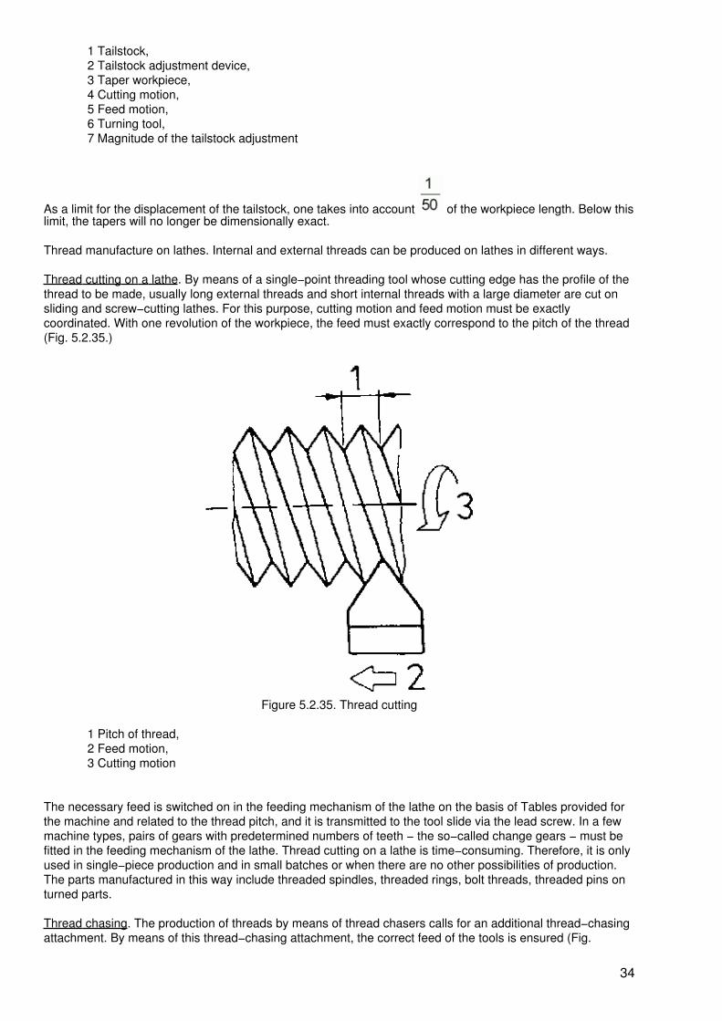
1 Tailstock,2 Tailstock adjustment device,3 Taper workpiece,4 Cutting motion,5 Feed motion,6 Turning tool,7 Magnitude of the tailstock adjustment
As a limit for the displacement of the tailstock, one takes into account of the workpiece length. Below thislimit, the tapers will no longer be dimensionally exact.
Thread manufacture on lathes. Internal and external threads can be produced on lathes in different ways.
Thread cutting on a lathe. By means of a single−point threading tool whose cutting edge has the profile of thethread to be made, usually long external threads and short internal threads with a large diameter are cut onsliding and screw−cutting lathes. For this purpose, cutting motion and feed motion must be exactlycoordinated. With one revolution of the workpiece, the feed must exactly correspond to the pitch of the thread(Fig. 5.2.35.)
Figure 5.2.35. Thread cutting
1 Pitch of thread,2 Feed motion,3 Cutting motion
The necessary feed is switched on in the feeding mechanism of the lathe on the basis of Tables provided forthe machine and related to the thread pitch, and it is transmitted to the tool slide via the lead screw. In a fewmachine types, pairs of gears with predetermined numbers of teeth − the so−called change gears − must befitted in the feeding mechanism of the lathe. Thread cutting on a lathe is time−consuming. Therefore, it is onlyused in single−piece production and in small batches or when there are no other possibilities of production.The parts manufactured in this way include threaded spindles, threaded rings, bolt threads, threaded pins onturned parts.
Thread chasing. The production of threads by means of thread chasers calls for an additional thread−chasingattachment. By means of this thread−chasing attachment, the correct feed of the tools is ensured (Fig.
34

5.2.36.).
Figure 5.2.36. Thread chasing
1 Guide cartridge,2 Guide jaw,3 Guide shaft,4 Tool holder with chaser,5 Workpiece,6 Three−jaw chuck,7 Cutting motion,8 Feed motion,9 In−feed motion with crank
The feed − of the same magnitude as the desired thread pitch − is taken from the guide cartridge, whichresembles a threaded bolt, by means of the guide cheek. The feed motion is then transmitted via the guideshaft to the tool holder with the thread chaser.
Thread chasing is particularly suitable for series and mass production of short threads, but it is also used forsmall lots. The size of the workpieces is limited by the clamping facilities offered by the lathe. The thread israpidly produced in one or two passes. For the mass production of threads, e.g. screws, die heads have to beused (Fig. 5.2.37.).
35

Figure 5.2.37. Thread−cutting head
1 Shank for clamping,2 Lever for opening to be used when workpiece has to be removed,3 Chaser jaws
Due to the fact that the four chaser jaws cut simultaneously in the die head, very short production times areachieved in one pass. Relieving. For the production of milling cutters, especially formed milling cutters,relieving lathes are used as special−purpose machines. By a special additional control device, the turning toolis given a relieving motion (Fig. 5.2.28.). Multi−edge turning. Multi−edge projections such as squares and thelike can be turned on cylindrical workpieces by means of attachments for lathes. By means of special turningheads and precisely coordinated motions, key surfaces, squares and hexagons can be turned on theworkpieces which comply with mean quality requirements (Fig. 5.2.39.).
Figure 5.2.38. Relieving
1 Cylindrical blank with grooves,2 Turning tool,3 Relieving motion in cutting,4 Return of the turning tool in the groove,5 Chip to be detached,
36

6 Detached chip,7 Relieved surface,8 Cutting motion,9 Relieved workpiece
Figure 5.2.39. Multi−edge turning
1 Special turning head,2 Tool,3 Cutting motion4 Workpiece,5 Workpiece motion,6 Workpiece with key surfaces,7 Square,8 Hexagon
Further procedures that can be performed on lathes are
− centring, drilling, reaming and countersinking (workpiece in a three−jaw chuck, tool in thetailstock)
− knurling straight−lined patterns and diamond knurling of surfaces of workpieces, e.g. onhandles
Summary:
Turning is a chip−detaching method with rotary cutting motion which is performed by theworkpiece. Various lathes offer a great variety of tooling operations.
5.2.2. Milling
Milling is a chip−detaching method with rotary cutting motion of the multi−edged tools − the milling cutters.The mainly straight feed motion is performed by the workpiece.
Workpieces are produced of plates or slabs and the like or surfaces are milled on semi−finished workpieces,grooves are milled into them or special shapes are produced (Fig. 5.2.40.).
37

Figure 5.2.40. Parts to be milled
Means of work
Milling cutter. Depending on the intended use, milling cutters are of different designs and sizes (see Table2.1.). The majority of types of milling cutters is standardized. In spite of the different designs, all milling cuttersare characterized by the same designation (Fig. 5.2.41.).
The face angles ?x, ?x, ?x are given only in cutters with helical teeth and they are not the tool angles. The faceangles can be measured in a simpler way than the tool angles (Vertical to the cutting edge). In straight−toothmilling cutters, the face angles and tool angles are of the same magnitude (Fig. 5.2.42.).
The tool angles are dependent upon the type of milling cutter, the material to be tooled and the milling cutterdesign.
Figure 5.2.41. Designations at the milling cutter
1 Workpiece body,2 Cutting edge,3 Surface under the cutting edge,4 Tooth back,5 chip space,6 Cutting face,7 Cutter helix,8 Tooth pitch,9 Milling cutter diameter,10 Diameter of the housing hole,11 Milling cutter width,?x face rake angle,? angle of inclination,?x face angle of clearance,
38

?x face cutting−edge angle
Figure 5.2.42. Straight−tooth milling cutter
? angle of clearance,? cutting−edge angle,? rake angle
The pitch t is an important design dimension which specifies the distance from cutter tooth to cutter tooth onthe milling cutter circumference. A large pitch t and, thus, a small number of teeth in the milling cutter offerssome advantages:
− the milling cutter has large chip spaces
− soft materials can be machined at high feed rates because the large chip spaces canaccomodate many chips
− the machine power required can be reduced for a smaller number of teeth
− the durability of the milling cutter edges is improved.
The angle of inclination ? indicates the position of the cutting edge of the cutter with respect to the central line(Figs. 5.2.41. and 5.2.42.). When the angle of inclination ? is greater than 0°, the cutting edges of the cutterhave a helix. Milling cutters are made with right−hand helix and left−hand helix. Milling cutters with a helixexcel in a smooth cut and a favourable chip disposal.
Keep in mind:
Milling cutters with a right−hand helix (or twist) are left−hand cutting while milling cutters with a left−handhelix are right−hand cutting.
For the milling of special shapes, formed milling cutters are used. The cutting edges of the formed millingcutters correspond to the shape to be produced in the workpiece. Formed milling cutters are relieved. Whensharpening by grinding, the rake angle ? = 0° must be strictly observed otherwise the form is changed. Forspecial milling operations, special milling cutters are required. Milling machines. For general millingoperations, horizontal milling machines (Fig. 2.4.14.), vertical milling machines (Fig. 2.4.15.) and universalmilling machines (horizontal and vertical) in different designs and sizes are used. For an economicalproduction of threads, short−thread milling machines and long−thread milling machines are built. Copy−millingmachines trace a precisely prepared pattern a so−called template, by means of special tracing devices andtransmit the tracing motions to the milling cutter which mills the workpiece accordingly. Special machines are
39

millers for the machining of very large workpieces, e.g. machine beds, and hob−type milling machines for theproduction of gears. Clamping accessories. The workpieces are fastened for milling to the machine table orcircular table mainly be means of machine vices and with clamps and clamping steps.
Dividing devices. For some milling operations, the clamping and aligning of workpieces is facilitated bydividing devices. Dividing devices, also known as indexing apparatuses, enable the exact dividing of aworkpiece circumference into equal parts without the necessity of marking by means of scribers.
Simple dividing device. For setting small divisions or spacings, e.g. T = 3, T = 4, T = 6, which are frequentlyfound in milling, simple dividing devices are used (Fig. 5.2.43). which are clamped on the machine table. Theworkpiece is held in the three−jaw chuck of the dividing device.
Figure 5.2.43. Simple dividing device
1 Notched disk,2 Notch,3 Ratchet,4 Three−jaw chuck,5 Base plate with clamping grooves
The desired division is adjusted by means of the ratchet in the notches of the dividing plate. The dividing aremade with different numbers of notches and can be exchanged at the dividing device.
The number of notches, or the divisional step, is calculated from the given number of notches of the dividingplate R and the division or spacing desired at the workpiece T. The number of notches is to be set at themachine, and it holds
where n = divisional step
R = number of notches of the dividing plate
T = desired division or spacing
The result must be integer !
Example of calculation. A hexagon is to be milled on a workpiece.
The dividing plate of the dividing device used has 24 notches.
How large is the required divisional step?
Given: T = 6
R = 24
To be found is n.
40

Solution:
n = 4
The required divisional step is equal to 4 notches. The workpiece is clamped in the dividing device and thefirst surface is milled on the workpiece. Then the notch plate and also the workpiece together with the plateare turned for the divisional step of four notches and the second surface of the hexagon is milled. The turningof the notch plate for four notches and the milling of the surfaces are repeated until all six surfaces of thehexagon have been milled.
Dividing head. The simple dividing device enables only small divisions because otherwise the notch platewould require an inconveniently large diameter for the large number of notches involved.
In order to use large divisions, e.g. T = 50, a dividing head is required (Fig. 5.2.44.). The dividing head is alsoclamped on the machine table and the workpiece is accomodated in the three−jaw chuck of the dividing head.
Figure 5.2.44. Dividing head
1 Three−jaw chuck,2 Housing with worm gear,3 Hole plate,4 Hole circle,5 Hand crank
The divisional step is adjusted by means of a crank in the hole circle of the dividing plate. The number of
41

holes to be set and the appertaining hole circle are looked up in tables which are delivered together with thedividing head. Due to an incorporated worm gearing, the dividing head enables the setting of even very largedivision, e.g. T = 300. For a series of certain divisions, change gears must be plugged on the dividing head.By means of the dividing head it is also possible to turn the workpiece through a certain angle for machiningso that surfaces can be milled which are located at a certain angle to each other. With a dividing head havinga gear ratio of the worm gearing of i = 40, one revolution of the crank is equal to a rotation of the clampedworkpiece through 9°. This shows that for an angle of 45° five crank revolutions (5 • 9) are required and for aright angle of 90° ten crank revolutions (10 • 9°).
When taking advantage of the hole circles, also known as index circles, all angles of whole numbers ofdegrees and even intermediate values can be set.
Procedure
In milling chips are detached by the rotating cutting motion of the milling cutter and the feed motion of theworkpiece. Several types of milling are achieved by various arrangements of the cutting edges at the millingcutter and different feed directions.
Due to different relative motions, climb−cut milling (Fig. 5.2.45.) and the conventional up−cut milling (Fig.5.2.45.) are possible.
Figure 5.2.45 Climb−cut milling
1 Cutting motion,2 Feed motion,3 In−feed
Figure 5.2.46. Up−cut milling
1 Cutting motion,2 Feed motion,3 In−feed
In climb−cut milling, the feed motion has the direction of the cutting motion. The chip is cut at its thickest pointat the beginning. Climb−cut milling calls for sturdy and powerful machines. The machine table must not showany longitudinal play (restricted possibility of motion) and the workpiece must be clamped very tightly and
42

safely
Keep in mind:
In climb−cut milling with table play or negligent clamping of the workpiece, the workpiece is drawn under themilling cutter. This will lead to the destruction of the milling cutter and the milling spindle. The workplace willbe damaged.
In up−cut milling, the feed motion is directed against the cutting motion of the milling cutter. The chip is initiallycut at its thinnest point. Up−cut milling is the most widely used method.
Procedure
Face milling. Milling cutters with circumferential and face cutting edges (end face mills, shank end mills) andcutter heads (also known as face milling cutter with inserted blades) are arranged in such a way that their toolaxis is vertical to the work surface to be machined. A uniform (usually rectangular) chip is detached by thecircumferential and face cutting edges. Face milling can be carried out with the tool axis in vertical orhorizontal position; in a few milling machine types, the milling spindle can be arranged obliquely (Fig. 5.2.47.).
Figure 5.2.47. Face milling
1 Plane surface of a workpiece,2 Offset workpiece surface,3 Oblique workpiece surface
Hobbing. Milling cutters which possess only circumferential cutting edges have their tool axis parallel to theworkpiece surface to be tooled. This leads to comma−shaped chips; the cutting edges of the cutter aresubjected to different loads.
Surface milling. In conventional milling, surfaces are milled on workpieces or given surfaces are smoothed.Large plane surfaces are milled by means of cylindrical cutters and face−milling cutters as well as cutterheads.
By mounting several milling cutters on a milling spindle, so−called gang cutters are obtained which lendthemselves to the milling of surfaces offset several times in an economical manner (Fig. 5.2.48.) Profiledsurfaces are milled by means of cutters of the former type (Fig. 5.2.49.).
43

Figure 5.2.48. Gang milling
1 Workpiece,2 Milling spindle,3 Cylindrical cutter,4 Helix cylindrical cutters,5 Straight−tooth plain cutter
Figure 5.2.49. Form milling
Groove milling. By means of different side and face milling cutters and grooving cutters, grooves of differentcross−sections can be milled (Fig. 5.2.50.).
Figure 5.2.50. Groove milling
1 Slotting,2 Straight groove,3 Prismatic groove,4 Round groove,5 Dovetail groove,6 T−groove,
Slot milling. Machine parts are frequently fastened by means of screws and bolts. In order to enable the
44

alignment of such machine parts or to adjust them properly, slots are milled. To increase the efficiency ofmachining and the durability of the slot milling cutters, the ends of the slots are frequently drilled by means oftwist drills and then the slot is milled (Fig. 5.2.51.).
Figure 5.2.51. Slot milling
1 Marked workpiece,2 Slot pre−drilled at its ends,3 Slot milling,4 Slot milling cutter,5 Cutting motion,6 In−feed motion,7 Feed motion
Copy milling. Workpiece of intricate shapes and convex and concave surfaces can be economically made oncopy milling machines with spherical shank milling cutters. Before milling, a master piece is made, The masterpiece has the same shape and dimensions as the workpiece to be milled and it consists of a material that iseasily machined (wood, plaster of Paris, light alloy).
Figure 5.2.52. Copy−milled workpieces
Workpieces made by copy milling are such having intricate internal shapes and punches for tools for initialshaping and forming. Turbine vanes and ships's propellers (Fig. 5.2.52.) are cast and forged and than finishedby copy milling.
Thread milling. The production of threads by milling is economical and involves only short manufacturingtimes as compared with other methods Special machines and thread−milling cutters are required, however.
Short−thread milling. Threads with 5 to 6 courses and a length of up to 100 mm are milled by means ofshort−thread milling cutters (Fig. 5.2.53.) on special milling machines. Short−thread milling cutters are relievedform cutters. The shape of the cutting edges corresponds to the profile of the screw thread.
45

Figure 5.2.53. Short−thread milling cutter
The workpiece is held by a chuck which is rotated by the machine. The rotating cutter is first fed to the depthof the screw thread. Then the workpiece is moved through one revolution while the short−thread milling cutterperforms an axial feed motion of one pitch of the thread. The screw thread is finished in one pass (Fig.5.2.54.).
Figure 5.2.54. Short−thread milling
1 Blank,2 Short−thread milling cutter,3 Cutting motion,4 Workpiece rotation,5 Feed motion,6 Thread pitch,7 finished workpiece
Short−thread milling is used for the production of screwthreads, for parts closing fittings of water, oil and gaspipes and motor−car parts.
Long−thread milling. Screw threads of great length (up to 2,000 mm and even longer in exceptional cases)can be made on long−thread milling machines. In their general structure, long−thread milling machinesresemble lathes but in the place of the tool holder there is a milling head with separate drive. The milling headholds long−thread milling cutters whose cutting edges are adapted to the thread profile to be cut. In milling thelong−thread milling cutters must be adjusted so that their position corresponds with the lead angle of thethread. The milling cutter performs the cutting motion. In−feed is effected in the desired depth of thread. Inmilling, the workpiece is rotating and, at the same time, the milling head is moved together with the rotatingmilling cutter axially for the thread pitch during one revolution of the workpiece. These two motions togetherresult in the feed which corresponds to the course of the thread (Fig. 5.2.55.).
46

Figure 5.2.55. Long−thread milling
1 Blank,2 Long−thread milling cutter,3 Cutting motion,4 Feed motion,5 Workpiece rotation,6 Thread pitch,7 Milled thread profile
Long−thread cutting is used for the series production of long thread spindles, e.g. lead screws for lathes,spindles for moving machine tables and for the production of cylindrical worms of worm gearings.
Gear−tooth milling. By means of form cutters for gear teeth (Fig. 5.2.56.), tooth spaces are individually milledout of disk−shaped blanks. The circumference of the workpiece is divided into the desired number of toothspaces by means of the dividing head.
Figure 5.2.56. Gear−tooth milling
1 Disk−type tooth shape milling cutter,2 Shank−type form cutter for gear teeth
The teeth remain at the workpiece while the spaces between them are milled out (Fig. 5.2.57.).
47
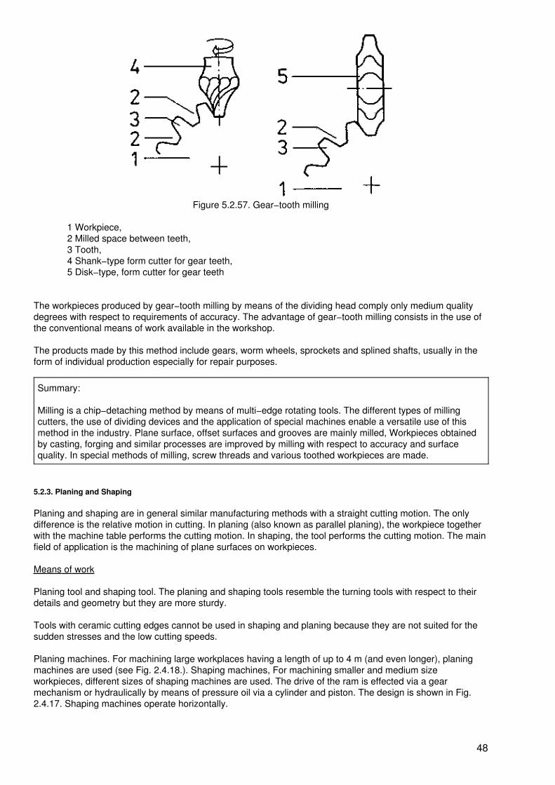
Figure 5.2.57. Gear−tooth milling
1 Workpiece,2 Milled space between teeth,3 Tooth,4 Shank−type form cutter for gear teeth,5 Disk−type, form cutter for gear teeth
The workpieces produced by gear−tooth milling by means of the dividing head comply only medium qualitydegrees with respect to requirements of accuracy. The advantage of gear−tooth milling consists in the use ofthe conventional means of work available in the workshop.
The products made by this method include gears, worm wheels, sprockets and splined shafts, usually in theform of individual production especially for repair purposes.
Summary:
Milling is a chip−detaching method by means of multi−edge rotating tools. The different types of millingcutters, the use of dividing devices and the application of special machines enable a versatile use of thismethod in the industry. Plane surface, offset surfaces and grooves are mainly milled, Workpieces obtainedby casting, forging and similar processes are improved by milling with respect to accuracy and surfacequality. In special methods of milling, screw threads and various toothed workpieces are made.
5.2.3. Planing and Shaping
Planing and shaping are in general similar manufacturing methods with a straight cutting motion. The onlydifference is the relative motion in cutting. In planing (also known as parallel planing), the workpiece togetherwith the machine table performs the cutting motion. In shaping, the tool performs the cutting motion. The mainfield of application is the machining of plane surfaces on workpieces.
Means of work
Planing tool and shaping tool. The planing and shaping tools resemble the turning tools with respect to theirdetails and geometry but they are more sturdy.
Tools with ceramic cutting edges cannot be used in shaping and planing because they are not suited for thesudden stresses and the low cutting speeds.
Planing machines. For machining large workplaces having a length of up to 4 m (and even longer), planingmachines are used (see Fig. 2.4.18.). Shaping machines, For machining smaller and medium sizeworkpieces, different sizes of shaping machines are used. The drive of the ram is effected via a gearmechanism or hydraulically by means of pressure oil via a cylinder and piston. The design is shown in Fig.2.4.17. Shaping machines operate horizontally.
48

Slotting machines, The motion of the ram is vertical; this is of particular advantage for certain jobs. Slottingmachines enable the arrangement of round tables and, consequently, rotary and slewing motions of theclamped workpiece. The vertically acting cutting forces are favourably taken up by the machine table.Clamping tools. For mounting the workpieces, machine vices, clamping steps and clamping irons areemployed on the machine tables which are provided with grooves for this purpose. The planing and shapingtools are clamped in special tool holders (Fig. 5.2.58.).
Figure 5.2.58. Tool holder for planing and shaping tools
1 Tool post,2 Clamping screw,3 Lid,4 Lid carrier5 Slot for adjustment,6 Crank,7 Scale in degrees
The tool is pushed into the groove of the tool post and clamped on the shank by means of the clampingscrew. The tool post is arranged on a lid which is lifted during the idle stroke. Tool post and lid are arrangedon the slewable lid carrier which can be moved up and down by means of a threaded spindle with crank.
Procedure
Planing. The workpiece mounted on the machine table performs the cutting motion, the stroke. During theworking stroke, the tool detaches chips while there is no chip removal during the return stroke. Due to aningenious drive, the return stroke is performed at a higher rate than the working stroke. After each doublestroke (i.e. working stroke and return stroke), a feed motion is effected by the tool together with the tool holderoutside of the workplace. The in−feed motion for the depth of cut is effected via the crank or together with theentire tool holder (Fig. 5.2.59.).
49

Figure 5.2.59. Planing
1 Planing tool,2 Workpiece,3 Cutting motion effected by the workpiece,4 Return motion,5 In−feed motion,6 Feed motion,7 Depth of cut,8 Feed
Shaping. The cutting motion − i.e. the stroke − is performed by the tool at the ram of the machine. The feedmotion after each double stroke is performed by the machine table together with the workpiece clamped inplace. The depth of cut is adjusted at the tool holder (Fig. 5.2.60.).
Figure 5.2.60. Shaping
1 Shaping tool,2 Workplace,3 Cutting motion by the tool,4 Return motion,5 In−feed motion,6 Feed motion,7 Depth of cut,8 Feed
Application
50

The simple planing and shaping tools and the easy way of sharpening them permits cutting underunfavourable conditions. This especially applies to the machining of castings, forgings and rolled workplaces.In these workpieces, sand inclusions, compaction, hardening and scale produces a crust which offers a highresistance to the cutting edge subjecting it to a high rate of wear. This high wear leads to high tool costs in thecase of other cutting methods.
Rough−machining. The planing and shaping of workpieces with crusts is performed as roughing, a methodwhere a large chip is removed and, consequently, the surface produced exhibits a high degree of roughness.It is necessary that the first chip is detached in such a manner that the crust is removed in order that the "soft"material underneath is reached.
In order to distribute the cutting action over a long portion of the cutting edge, a setting angle ? of 45° to 70°should be observed (Fig. 5.2.61.). The cutting depth should be 3 to 5 times the feed. The tool should beclamped short.
Figure 5.2.61. Rough−machining
1 Roughing tool,2 Workpiece,3 Chip,4 Tooling marks,5 Depth of cut,6 Feed,? setting angle
Finish−machining. When the surface quality requirements are in the medium range, finishing or workpiecesufaces is effected by the methods of planing and shaping. For finish−machining, pointed tools or broadfinishing tools are used. Broad finishing tools, also known as broad−nose finish−tools, ensure a higher rate offeed and reduce the manufacturing time.
Cross planing. Cross planing, also known as transverse planing, is a method for machining horizontalsurfaces. This method of planing is most widely used (Fig. 5.2.62.).
51
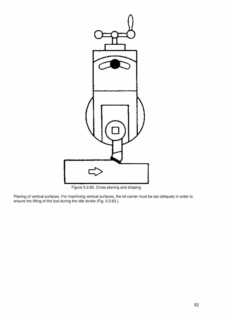
Figure 5.2.62. Cross planing and shaping
Planing of vertical surfaces. For machining vertical surfaces, the lid carrier must be set obliquely in order toensure the lifting of the tool during the idle stroke (Fig. 5.2.63.).
52

Figure 5.2.63. Planing and shaping of vertical surfaces
For slotting, the feed must be set manually at the crank of the tool post. In large planing machines, amechanical feed is possible.
In slotting machines, the surfaces produced at the workpiece during cutting are vertical. The tool must beremoved from the workpiece during the return stroke.
Groove planing. When the quality requirements are limited, grooves are readily planed or shaped. When thequality requirements are higher, it is more economical to pre−plane the grooves. Plunge grooves andT−grooves are commonly produced (Fig. 5.2.64.).
Figure 5.2.64. Groove planing
1 Plung tool,2 Workpiece,3 Relief grinding,4 T−groove tool
53

By means of slotting machines, internal grooves in given holes are favourable produced (Fig. 5.2.65.)
Figure 5.2.65. Internal−groove shaping
1 Blank,2 Vertically shaping tool,3 Cutting motion,4 Feed motion,5 Finishing workpiece,6 Internal groove
Summary:
Planing and shaping (including slotting) are chip−detaching methods having a straight cutting motion. Thesimple tools and the easy way of sharpening them permit the use especially for the machining of castingsand forgings to remove the material crust. These two methods are primarily used for roughing and similarprocesses.
5.2.4. Drilling
Drilling is a chip−detaching method with rotating cutting motion and straight feed motion.
The drilling tools are single−edged, two−edged and multi−edged. By drilling, workpieces are not newlyproduced. In initially shaped, formed or by cutting obtained workpieces
− through holes or blind holes (Fig. 5.2.66.) are drilled− pre−produced holes are enlarged in their diameters− the accuracy to size and the surface quality of pre−produced holes are improved.
54

Figure 5.2.66. Through holes and blind holes
1 Through hole,2 Blind hole,3 Workpiece,4 Depth of drilling,? = internal diameter of the hole
Means of work
Drilling tools. The various jobs to be performed call for different drilling tools. The use of drilling tools isdetermined by
− the material to be tooled− the thickness of the workpiece (sheet metal) to be tooled− the desired diameter of the hole− the depth of the hole specified− the initial shape (solid or pre−produced).
Twist drill (see Fig. 2.2.27.). The cutting wedge of the twist drill can be defined by the tip (Fig. 5.2.57.).
55

Figure 5.2.67. Cutting−edge geometry of the twist drill
1 Cutting edge,2 Surface below the cutting edge,? clearance angle,? cutting−edge angle,? rake−angle = helix angle of the flutes,? point angle
The rake angle ? is given by the helix angle of the flutes (with steel from 20 to 30°). The angle of clearance ?and the point angle ? (in steel from 118 to 124°) are ground.
Frequently, twist drills are ground by hand. For sharpening by grinding, the following must be observed:
− the point must be ground so that it is exactly in the centre of the drill
− the cutting edges must be of the same length
− the angle of clearance ? must be ground uniformly over the entire surface below the cuttingedge (visible by the point behind the land).
For drilling thin sheet metal, twist drills with centre grinding (Fig. 5.2.68.) are favourable.
56

Figure 5.2.68. Centre grind for twist drills
? = diameter of the hole
Due to the small ground centring point, the drill will easily find the punch mark when applied to the workpieceand will start cutting well. The particular advantage of the centre grind is the fact that the drill will not hookwhen the cutting edges drill the end of a through hole.
Twist drills consist of high−speed steel or super high−speed steel. For hard metallic materials and especiallyfor drilling hard non−metallic materials such as concrete, ceramic materials, rock and the like, twist drills withcemented carbide cutting edges are commercially available. Deep−hole twist drills possess long cutting edgesand in special cases cooling channels.
Centring drills (see also Fig. 2.2.26.) are short and very rigid drilling tools which are standardized both withrespect to their shape and their dimensions.
Boring bars consist of a shank for clamping together with a boring bit (Fig. 5.2.69.).
Figure 5.2.69. Boring bar
1 Shank,2 Boring bit,3 Clamping screw
The shank should have a large diameter in order to take up the cutting forces safely. The tool geometry of theboring bit corresponds to that of a turning tool but it is smaller.
The setting of the boring bit results in the diameter to be drilled. For an economical manufacture, boring barswith several bits are used.
57

Circular cutters (see Fig. 2.2.6.) possess a boring bit which ensures settings for drilling large diameters.
Subland drills. These drills are also known as combination tools. They are economical in use for themachining of larger lots of workpieces. With one setting of the workpiece and one pass, several operations,are performed (at the same time or subsequently). For example, multi−cut stepped drills (see Fig. 2.2.26.) andtwist thread drills are included in this type of drills.
Drilling machines. Drilling machines are built in different sizes and types for various methods of drillings. Smallworkpieces are drilled on bench drilling machines, medium−size workpieces on column−type drilling machines(see also Fig. 2.4.13.). For drilling very large workpieces, radial drilling machines (Fig. 5.2.70.) are required.The workpieces a re mountedon stationary tables and the drill is moved up to the drilling point.
Figure 5.2.70. Radial drilling machine
1 Column,2 Cross−beam holder,3 Cross−beam,4 Spindle box with gearing,5 Motor,6 Drilling spindle,7 Flat machine table,8 High workpiece,9 High machine table,10 Flat workpiece.
For this purpose, the traverse can be adjusted vertically and turned through 360°. The drilling head can bemoved laterally on the traverse. The working range of the radial drilling machine obtained in this way is largeand enables the mounting of several workpieces on various machine tables.
Hand drilling machines are required for repairs and assembling operations.
58

Special drilling machines. For drilling holes of a great depth, deep−hole drilling machines are required. Indeep−hole drilling machines, the mounted workpiece rotates while the deep−hole drill is rigidly clamped. Finedrilling machines have very acurate spindle guides in order to drill holes having a diameter below 1 mm.
Multi−spindle drilling machines operate at the same time with several drills in various spindles.
Procedure
In normal drilling, the workpiece is clamped in a machine vice or smaller vice on the machine table while thepunch is directed to the point of the drill. The drill in the drilling spindle performs the rotating cutting motionand the (usually) vertical feed motion. The feed motion can be effected manually via a lever of mechanicallyby means of a feed gearing. Anin−feed motion is not possible with twist drills, hence, for a larger diameter tobe drilled a larger drill must be used (Fig. 5.2.71.).
Figure 5.2.71. Procedure of drilling
1 Workpiece,2 Punch,3 Starting motion,4 Cutting motion,5 Feed motion,6 Chip,7 Finished hole
The chips involved are discharged from the hole by the helical flute of the twist drill. When drilling deep holes,the drilling operation must be interrupted in order to remove the drill from the hole and to discharge the largeamount of chips.
In drilling, the workpiece must be secured against being carried along the by rotating drill. Theclamping tools for the workpieces must be large enough in order to retain the latter safely.When the workpiece is kept by hand alone, there is a great danger of being hurt !
Application
Drilling. By means of twist drills, blind holes and through holes are drilled. The accuracy to size achievedcomplies with medium quality requirements, the surfaces of the holes are rough−machined.
Drilling out. In order to produce holes in plates or cut out portions from plates, the contours are provided withholes at small spacings and then the part is further separated by means of a suitable chisel.
Preliminary drilling. Holes to be drilled that have a large diameter are predrilled by means of a drill having asmaller diameter. The drill with the desired diameter will then operated more favourably and requires a lowercutting force because the chisel edge of the drill operates freely (Fig. 5.2.72.).
59
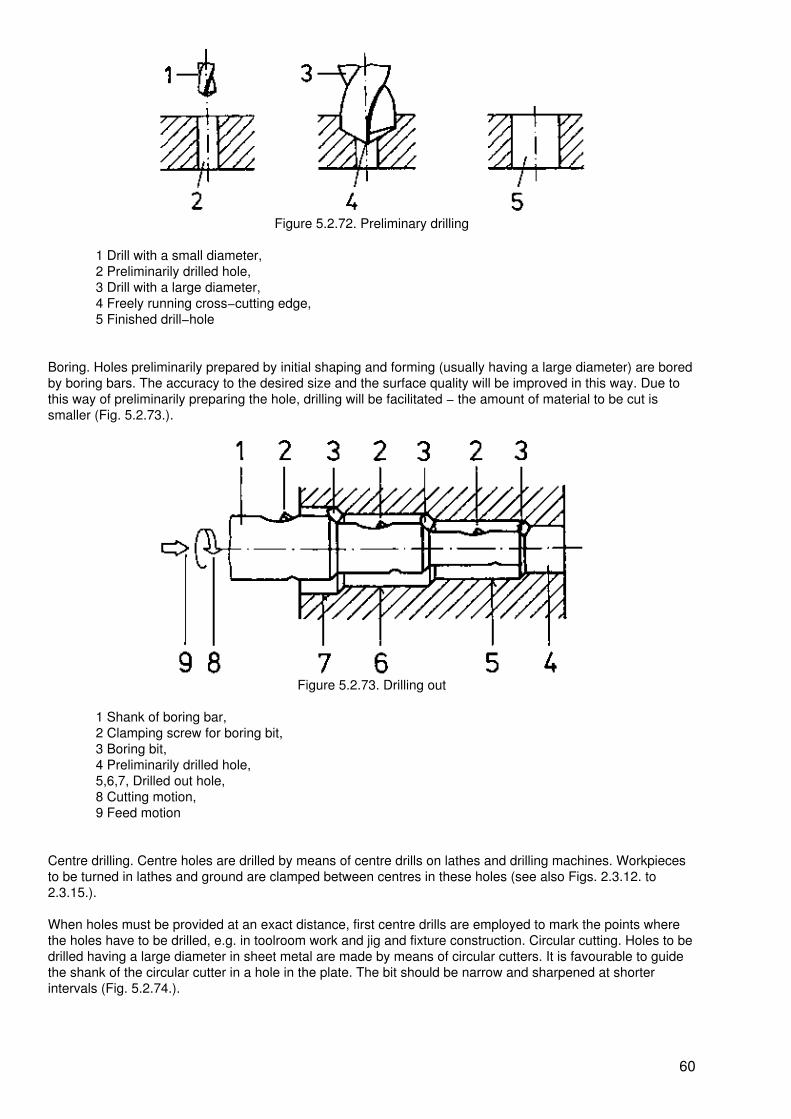
Figure 5.2.72. Preliminary drilling
1 Drill with a small diameter,2 Preliminarily drilled hole,3 Drill with a large diameter,4 Freely running cross−cutting edge,5 Finished drill−hole
Boring. Holes preliminarily prepared by initial shaping and forming (usually having a large diameter) are boredby boring bars. The accuracy to the desired size and the surface quality will be improved in this way. Due tothis way of preliminarily preparing the hole, drilling will be facilitated − the amount of material to be cut issmaller (Fig. 5.2.73.).
Figure 5.2.73. Drilling out
1 Shank of boring bar,2 Clamping screw for boring bit,3 Boring bit,4 Preliminarily drilled hole,5,6,7, Drilled out hole,8 Cutting motion,9 Feed motion
Centre drilling. Centre holes are drilled by means of centre drills on lathes and drilling machines. Workpiecesto be turned in lathes and ground are clamped between centres in these holes (see also Figs. 2.3.12. to2.3.15.).
When holes must be provided at an exact distance, first centre drills are employed to mark the points wherethe holes have to be drilled, e.g. in toolroom work and jig and fixture construction. Circular cutting. Holes to bedrilled having a large diameter in sheet metal are made by means of circular cutters. It is favourable to guidethe shank of the circular cutter in a hole in the plate. The bit should be narrow and sharpened at shorterintervals (Fig. 5.2.74.).
60

Figure 5.2.74. Circular cutting
1 Plate,2 Desired hole,3 Hole for the guide pin,4 Finished hole,5 Material cut out
Deep−hole drilling. When the depth of the hole is ten times the hole diameter and more, then drilling is calleddeep−hole drilling. Large depths can be drilled by means of deep−hole drills which are mainly used ondeep−hole drilling machines. It is used, for example, for drilling cooling ducts into ingot moulds andthermosetting plastic moulds. Further applications are the drilling of rifle barrels and hollow shafts.
Fine drilling. Holes having a diameter below 1 mm are drilled on fine drilling machines. This method of drillingis used for the production of nozzles, screens and the like and in precision mechanics.
The use of subland drills. Subland drills perform different operations in one pass, depending on their design.
Multi−cut stepped drills drill holes and countersink them for countersinking screws and rivet heads (Fig.5.2.75.).
Figure 5.2.75. Multi−cut step−drilling
1 Workpiece with punch mark,2 Drilling3 Drilling and countersinking,4 Finished hole with countersink
Spiral thread drills drill the core−hole for the internal thread and cut the internal thread into the hole (Fig.5.2.76.). The feed must correspond to the pitch of the thread.
61

Figure 5.2.76. Spiral−thread drilling
1 Workpiece with punch mark,2 Drilling,3 Thread−cutting,4 Finished internal thread
5.2.5. Reaming
Reaming is a chip−detaching method of manufacture. Blind holes and through holes are reamed by means ofmulti−edged rotating tools in order to improve the accuracy to size and the surface quality.
By means of reamers, fine chips are removed from the roughed surfaces of the drilled holes so that thesurface roughness is reduced. This means that the surface is finish−machined. The diameter of the reamedhole is determined by the diameter of the reamer.
Means of work
Machine reamers. Machine reamers are employed on drilling machines and lathes (see Section 2.2. and Figs.2.2.28. to 2.2.31.).
Hand reamers. To improve the guiding of the tool, hand reamers are provided with a starting taper that islonger than that of machine reamers. The shank ends in a square. A tap wrench is plugged on this square foroperating the hand reamer (Fig. 5.2.77.).
62

Figure 5.2.77. Reamer and tap wrench
For sharpening reamers, tool grinding machines are required. Any grinding by hand renders the reamersuseless.
Keep in mind:
Reamers, and especially the cutting part of them, must be treated with every care. They should be kept insleeves or specially prepared plug boards. When reamers are deposited in a break during working, a softsupport must be provided (wood, plastic material, felt). Reamers must not be put one upon the other. If theteeth or the cutting edges of a reamer are but slightly damaged, the reamer must be sharpened.
Procedure
The hole to be reamed must have an allowance of 0.1 to 0.2 mm included in its diameter, that is to say, thatthe hole must be drilled by means of a drill having a smaller diameter than the finish−reamed hole.
Example: When a reamed hole is required to have a diameter of 10 mm, a drill having a diameter of 9.8 mm isto be used.
The workpiece with the hole is mounted and the reamer vertically turned into the hole. The rotating cuttingmotion and the axial feed motion are performed manually (hand reamers) or mechanically (machine reamers).The depth of cut is derived from the allowance (admeasure) of the hole. A removal of chips is effected only bythe chamfer of the reamer teeth. The remaining length of the cutting edge is used for after−smoothing thesurface of the hole and for guiding the reamer (Fig. 5.2.78.).
63

Figure 5.2.78. Procedure of reaming
1 Reamer,2 Cutting motion,3 Feed motion,4 Workpiece,5 Starting taper,6 Smoothing part of the cutting edge,7 Guide,8 Chip
Through holes can be reamed over their entire length because the reamer can be turned through them (Fig.5.2.79.).
Blind holes can be reamed only down to a certain depth. The remaining part of the blind hole having thelength of the chamfer of the reamer cannot be reamed (Fig. 5.2.80.).
64

Figure 5.2.79. Reaming a through hole
1 workpiece with hole,2 Reamer,3 Allowance,4 Reamed through hole
Figure 5.2.80. Reaming a blind hole
1 Workpiece with blind hole,2 Reamer with a short starting taper,3 Reamed blind hole,4 Reamed length
Keep in mind:
Reaming calls for particular skill. The reamer must be applied vertically and turned without undue force incutting direction. When tilting the reamer and turning it in the wrong direction, the cutting edges of thereamer will be destroyed and the surface of the hole damaged. When reaming blind holes, the reamer mustnot touch the base of the hole.
Application
Holes which must have finish−machined surfaces and a high accuracy to size have to be reamed. They arerequired
− for pressing parts in place, e.g. bushes, antifriction bearings and pins− for holes to be used as bearings, e.g. for axles and shafts− for highly stressed riveted and screwed connections.
Reaming of internal tapers. Internal tapers having a small diameter and a small taper ratio (e.g. 1:k = 1:100),
65
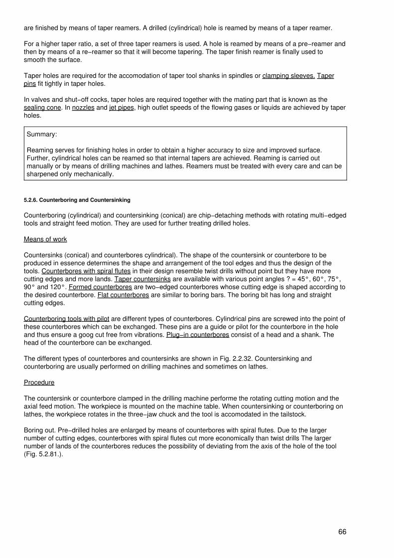
are finished by means of taper reamers. A drilled (cylindrical) hole is reamed by means of a taper reamer.
For a higher taper ratio, a set of three taper reamers is used. A hole is reamed by means of a pre−reamer andthen by means of a re−reamer so that it will become tapering. The taper finish reamer is finally used tosmooth the surface.
Taper holes are required for the accomodation of taper tool shanks in spindles or clamping sleeves. Taperpins fit tightly in taper holes.
In valves and shut−off cocks, taper holes are required together with the mating part that is known as thesealing cone. In nozzles and jet pipes, high outlet speeds of the flowing gases or liquids are achieved by taperholes.
Summary:
Reaming serves for finishing holes in order to obtain a higher accuracy to size and improved surface.Further, cylindrical holes can be reamed so that internal tapers are achieved. Reaming is carried outmanually or by means of drilling machines and lathes. Reamers must be treated with every care and can besharpened only mechanically.
5.2.6. Counterboring and Countersinking
Counterboring (cylindrical) and countersinking (conical) are chip−detaching methods with rotating multi−edgedtools and straight feed motion. They are used for further treating drilled holes.
Means of work
Countersinks (conical) and counterbores cylindrical). The shape of the countersink or counterbore to beproduced in essence determines the shape and arrangement of the tool edges and thus the design of thetools. Counterbores with spiral flutes in their design resemble twist drills without point but they have morecutting edges and more lands. Taper countersinks are available with various point angles ? = 45°, 60°, 75°,90° and 120°. Formed counterbores are two−edged counterbores whose cutting edge is shaped according tothe desired counterbore. Flat counterbores are similar to boring bars. The boring bit has long and straightcutting edges.
Counterboring tools with pilot are different types of counterbores. Cylindrical pins are screwed into the point ofthese counterbores which can be exchanged. These pins are a guide or pilot for the counterbore in the holeand thus ensure a goog cut free from vibrations. Plug−in counterbores consist of a head and a shank. Thehead of the counterbore can be exchanged.
The different types of counterbores and countersinks are shown in Fig. 2.2.32. Countersinking andcounterboring are usually performed on drilling machines and sometimes on lathes.
Procedure
The countersink or counterbore clamped in the drilling machine performe the rotating cutting motion and theaxial feed motion. The workpiece is mounted on the machine table. When countersinking or counterboring onlathes, the workpiece rotates in the three−jaw chuck and the tool is accomodated in the tailstock.
Boring out. Pre−drilled holes are enlarged by means of counterbores with spiral flutes. Due to the largernumber of cutting edges, counterbores with spiral flutes cut more economically than twist drills The largernumber of lands of the counterbores reduces the possibility of deviating from the axis of the hole of the tool(Fig. 5.2.81.).
66

Figure 5.2.81. Boring out
1 Preliminarily bored workpiece,2 Counterbore with spiral flutes,3 Cutting motion,4 Feed motion,5 Hole bored out to enlarge the diameter
Counterboring and countersinking. To accomodate heads of screws and rivets, holes are provided withcylindrical or conical counterbores or countersinks (Fig. 5.2.82.).
For seats of balls, spherical counterbores are provided.
By means of taper countersinks, holes can be provided with chamfers and the can be deburred.
Figure 5.2.82. Conical countersink
1 Workpiece with hole,2 Conical countersink.3 Cutting motion,4 Feed motion,5 Conical countersink
Spot−facing. In castings and forgings, flat surfaces contacting holes are improved in their surface quality byflat counterbores (Fig. 5.2.83.)
67

Figure 5.2.83. Spot−facing
1 Workpiece, with a rough surface, drilled,2 Knife,3 Shank,4 Cutting motion,5 Feed motion,6 Spot−faced surface
In this way, screw heads are provided with a proper supporting surface. For adjacent components, supportingand working surfaces are provided. The appearance is improved and the risk of hurts is reduced due to the,smoothing of the surfaces.
Summary:
Preliminarily drilled holes are further tooled by counterboring and countersinking. Different types ofcounterbores and countersinks are used on drilling machines and lathes to subject holes to boring−out,countersinking and counterboring, and spot−facing. The surfaces machined are of the quality provided byroughing.
5.2.7. Sawing
Sawing is a chip−detaching method for separating workpieces into two and more parts by means ofmulti−edged tools. The various sawing method are distinguished by the saw blades and the relative motionsinvolved.
Means of work
Saw blades. There are hand saw blades (see Fig. 2.1.33.) and for sawing machines, hacksaw blades, circularsaw blades and band−saw blades are used.
68

Figure 5.2.84. Circular saw blade with cemented carbide tips
1 Saw blade,2 Cemented carbide tip
For heavy cuts, circular saw blades are provided with cemented carbide tips (Fig. 5.2.84.).
The cemented carbide tips are ground in different ways.
Segmental saw blades consist of a basic body (disk) on which the exchangeable tooth segments arefastened. For manual sawing, hand hacksaw (Fig. 2.1.33.) are used.
Sawing machines. For mechanical sawing, hacksaw machines, circular sawing machines and band sawingmachines are used (see also Figs. 2.4.21. to 2.4.23.).
Procedure
The sawing methods are determined by the various cutting motions of the different tools. An in−feed motion isnot possible in sawing. The depth of cut is equal to the width of the saw kerf and is given by the width of thecutting edge.
Hacksaws. The cutting motion of manual and mechanical hacksaws is a straight working stroke while the feedmotion is vertical. In the return stroke, the idle stroke, of the hand hacksaw, no pressure is applied to the saw.In hacksaw machines, the saw blade is slightly lifted during the return stroke (Fig. 5.2.85.).
Circular saws. In circular sawing, the saw blade performs the rotating cutting motion. The feed motion iseffected by the tool slide together with the saw blade (Fig. 5.2.86.).
69

Figure 5.2.85. Hacksaw operation
1 Workpiece,2 Hacksaw blade,3 Bow,4 Cutting motion (working stroke),5 Feed motion,6 Return stroke (idle stroke)7 Lifting the saw blade during the return stroke
Figure 5.2.86. Circular saws
1 Workpiece,2 Circular saw blade,3 Cutting motion,4 Feed motion
Band saws. The band−saw blade is driven via rolls and reversed outside of the workpiece. In this way, anuninterrupted straight vertical cutting motion is ensured. The feed motion is effected by hand by means of theworkpiece and takes a straight or curved course according to specifications (Fig. 5.2.87.).
70

Figure 5.2.87. Band saws
1 Workpiece,2 Band saw blade,3 Saw cut,4 Cutting motion,5 Straight feed motion
Application
Hand hacksaws. Sections and pipes having a small cross−section are separated manually and small lots arecut to the desired length. Sawing out is defined as the separation of parts out of plates with a straight courseof cutting. By sawing off, e.g. of corners, the shape of a workpiece is produced. For the further treatment of aworkpiece by bending, sawing in is required (Fig. 5.2.88.).
Figure 5.2.88. Sawing in
1 Workpiece with slots sawn in;2 Workpiece after bending
Hacksaw machines. In the field of prefabrication for structural steelwork and pipe installation, sections ofmedium size cross−section are sawn to the specified lengths and blanks for machining by lathes, e.g. roundstock, or by milling, e.g. square and rectangular bars, are sawn by these sawing machines.
Circular saws. Circular sawing is more accurate to size than hacksawing. It is used for separating profileshaving large cross−sections and for sawing off rising gates and riser outgates on castings. Circular sawblades having smaller diameters are employed on milling machines for cutting slots. Slots are very smallgrooves as, for example, in collets.
71

Figure 5.2.89. Sawing an opening by means of the band saw
1 Pre−drilled workpiece with marking,2 Inserting the separated band saw blade,3 Band−sawing,4 Workpiece with an opening sawn
Band saws. Band sawing enables the sawing out, sawing off and sawing in with straight and curved course ofcutting. Openings are sawn out and then machined further. The opening is pre−drilled in a width that is slightlywider than the band−saw blade. The band−saw blade is separated at its weld seam, drawn through the drilledholes and, in the machine, brazed or welded together. When the opening is sawn out, the band−saw blade isagain separated and drawn out of the opening (Fig. 5.2.89).
Summary:
The three sawing methods − hacksaw sawing, circular sawing and band sawing − are mainly used in thefield of prefabrication where the sawn kerfs comply with low quality requirements as to accuracy to size andsurface quality. The main field of application is the separating of sectional bars and rods and of pipes.
When small lots have to be produced, sawing out, sawing off and sawing in are the methods to be used.Circular sawing is also used for sawing slots. Band sawing enables curved cuts and the sawing of openingsin workpieces.
5.2.8. Broaching
In large series and mass production, especially of small and medium−size workpieces, broaching iseconomical because of the short manufacturing times and the attainable surface quality and accuracy to size.The internal and external shapes of workpieces, that can be produced by broaching, can be obtained by othermethods of manufacturing only at high costs (Fig. 5.2.90.).
Figure 5.2.90. Workpiece with broached internal profiles
On the other hand, broaching calls for special, complicated and expensive tools and broaching machines forany desired shape.
Means of work
Broaching tools are multi−teeth cutting tools with staggered teeth. The design of the broaching tools is
72

different and determined by several factors:
− Working range. For the machining of external surfaces on workpieces, external broaches(surface broaches) are available. For internal surfaces, e.g. drilled holes, openings and thelike, internal broaches of a quite different design are required.
− Application of force. From the broaching machine, the cutting force (chip−detaching force)is transmitted to the broaches. Pull broaches are drawn by the machine, pressure broachesare pressed.
− Material of the workpiece. The geometry of the tool teeth is dependent on the strength ofthe material to be machined. The strength also determines the tooth feed.
− Length of broaching cut. This length is the workpiece length to be machined by broaching.Together with the tooth feed, it determines the necessary size of the chip space and, thus, thetooth spacing.
− Performance of the broaching machine. The number of cutting edges in engagement, thelength of the cutting edges and the strength of the material to be machined call for a certainperformance of the machine. In case of a large length of the broaching cut and a large chipvolume, several broaches are required which are employed in succession.
Simple internal broaches. A guide piece of structural steel with shank and end piece for clamping is made,having the same cross−section as the given drilled hole or the opening. One or several strips with broachingteeth are inserted into this basic body; the teeth are of tool steel or high−speed steel (Fig. 5.2.91.).Complicated internal broaches. For the all−sided machining of the opening, internal broaches are made in onepiece of tool steel or high−speed steel (Fig. 5.2.92.).
Figure 5.2.92. Simple internal broach
1 Shank,2 Guide part,3 Inserted clearing ledge,4 End piece
Figure 5.2.93. Complicated internal broach
1 Shank,2 Receptacle with the cross−section of the prepared hole,3 Serration,4 Guide piece with the cross−section of the broached opening,5 End piece
73
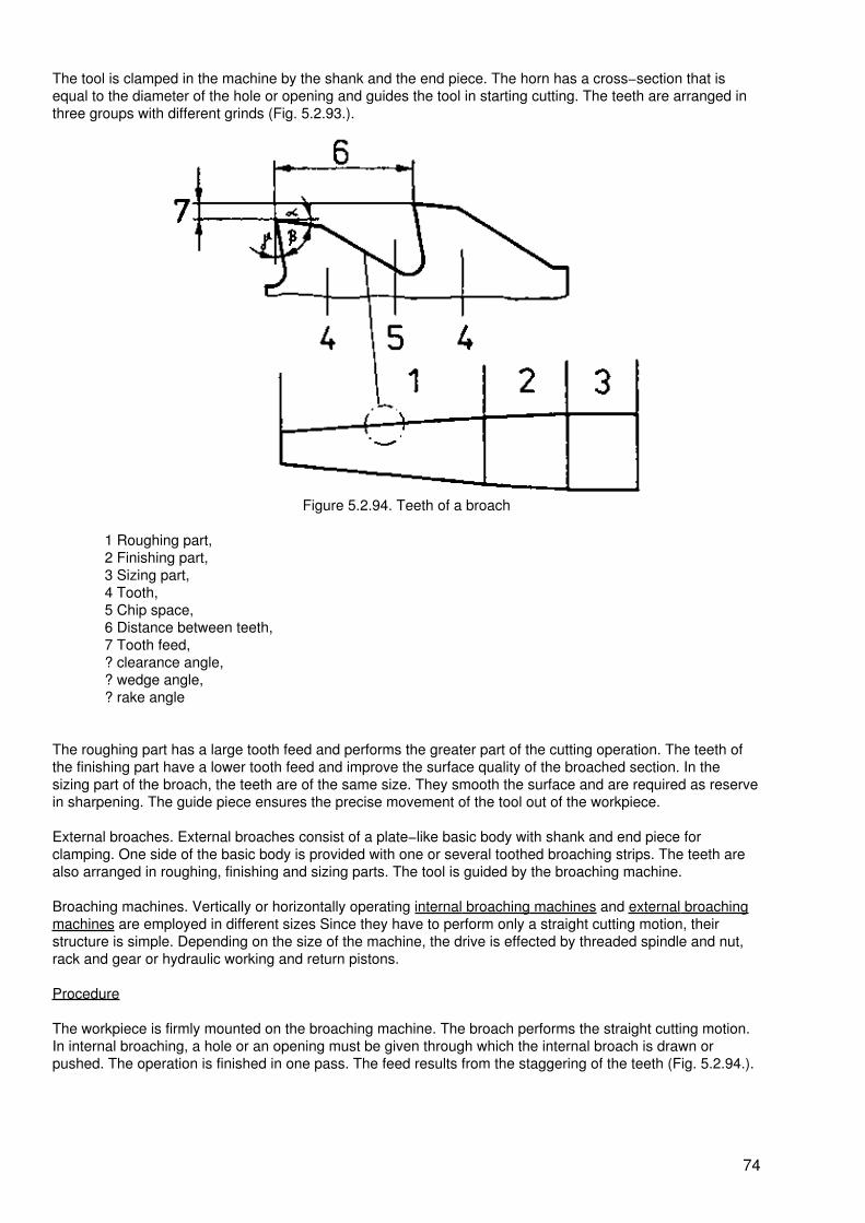
The tool is clamped in the machine by the shank and the end piece. The horn has a cross−section that isequal to the diameter of the hole or opening and guides the tool in starting cutting. The teeth are arranged inthree groups with different grinds (Fig. 5.2.93.).
Figure 5.2.94. Teeth of a broach
1 Roughing part,2 Finishing part,3 Sizing part,4 Tooth,5 Chip space,6 Distance between teeth,7 Tooth feed,? clearance angle,? wedge angle,? rake angle
The roughing part has a large tooth feed and performs the greater part of the cutting operation. The teeth ofthe finishing part have a lower tooth feed and improve the surface quality of the broached section. In thesizing part of the broach, the teeth are of the same size. They smooth the surface and are required as reservein sharpening. The guide piece ensures the precise movement of the tool out of the workpiece.
External broaches. External broaches consist of a plate−like basic body with shank and end piece forclamping. One side of the basic body is provided with one or several toothed broaching strips. The teeth arealso arranged in roughing, finishing and sizing parts. The tool is guided by the broaching machine.
Broaching machines. Vertically or horizontally operating internal broaching machines and external broachingmachines are employed in different sizes Since they have to perform only a straight cutting motion, theirstructure is simple. Depending on the size of the machine, the drive is effected by threaded spindle and nut,rack and gear or hydraulic working and return pistons.
Procedure
The workpiece is firmly mounted on the broaching machine. The broach performs the straight cutting motion.In internal broaching, a hole or an opening must be given through which the internal broach is drawn orpushed. The operation is finished in one pass. The feed results from the staggering of the teeth (Fig. 5.2.94.).
74

Figure 5.2.94. Internal broaching
1 Workpiece with prepared hole,2 Operation,3 Cutting motion,4 Workpiece with broached internal profile
In external broaching, the external broach is pushed or drawn over the surface to be machined. Chips aredetached by the staggered teeth over the full width of the tool,
Application
Due to the high costs of the tool, broaching is only economical when large numbers of workpieces have to beproduced or when other methods are even more expensive.
By internal broaching, usually cylindrical drilled holes are broached into internal profiles (Fig. 5.2.95.).
Figure 5.2.95. Examples of internal broaching
By external broaching, profiled surfaces and grooves of special shapes are made (Fig. 5.2.96.).
Figure 5.2.96. Examples of broaching externally profiled surfaces and grooves
Helical grooves in internal and external surfaces call for special machines which, besides the straight cuttingmotion, perform a rotational motion. Helical grooves (Fig. 5.2.97.) are required as lubricating grooves and forsafeguarding certain sequences of motions of components.
75

Figure 5.2.97. Workpiece with helical grooves
For drilled holes and grooves, broaching is also used as the finishing operation.
Summary:
Internal and external profiles are made by broaching in one pass and, thus, in a very short manufacturingtime. The broaching tools, which are made individually, have a staggering of teeth which results in the feed.Broaching is carried out by means of broaching machines of different designs.
5.2.9. Scraping
Scraping is a precision finishing process of machine−finished surfaces of workpieces. Due to a negative rakeangle of the tools, very fine and thin chips are only removed.
Means of work
Scrapers. The tools for scraping (sometimes also called shaving) − the scrapers − are tools of a simpledesign. Flat scrapers are used manually as pull scraper and push scraper (Fig. 5.2.98.), mechanically they areonly used as push scrapers.
Figure 5.2.98. Pull scraper and push scraper
76

1 Workpiece,2 Pull scraper,3 Pulling motion,4 Push scraper,5 Pushing motion? clearance angle,? wedge angle,? rake angle
Triangular scrapers (Fig. 5.2.99.) have three cutting edges and are available in two different designs.Half−round scrapers have curved cutting edges and are used in a hollow and in a solid form.
Figure 5.2.99. Triangular scraper
Rotary gear shaving cutters. As special tools for gear tooling, rotary gear shaving cutters are commerciallyavailable. Their shape is that of a toothed wheel. By slotting the teeth several times, cutting edges and chipspaces are obtained (Fig. 5.2.100.).
Figure 5.2.100. Tooth of rotary gear shaving cutter
1 Slots
Surface plates. Sturdy plates are cast of strong and dense grey cast−iron and one surface of the plate issmoothed by precision finishing. The smoothness of the surface attained is decisive for the quality of theshaving work to be done later. Inking shafts are specifically made means of work in the respective diameterswith polished cylindrical surfaces and high accuracy to size. Inking pastes are pasty dyestuffs of an intensered or blue colour which will not harden. Scraping machines facilitate the heavy physical labour involved inscraping. For gears, special machines must be used.
Procedure
77

Inking. Inking is defined as the application of a special inking paste to the surface plate and the workpiece tobe machined. This shows the spots and points on the surface of the workpiece which must be scraped (orshaved). By means of a piece of cloth or leather, the inking paste is applied to the surface plate uniformly. Theworkpiece is placed with the surface to be scraped on the surface plate and, applying a slight pressure,moved on the surface plate in all directions (Fig. 5.2.101.).
Figure 5.2.101. Inking
1 Surface plate,2 Applied inking paste,3 Workpiece,4 Inking motion of the workpiece
An inking pattern is produced on the surface of the workpiece. Into depressions which are rather deep, noinking pas will get. These depressions remain bright (metallic bright). The inking paste will be rubbed awayfrom elevations on the workpiece surface; consequently, they will be weakly coloured. In slight depressions,the inking paste will be rubbed − they appear intensely coloured.
Scraping. The surface of the workpiece will be scraped according to the inking pattern. The weakly colouredpoints − the elevations − will be scraped away individually. The cutting motion performed in this process isflatly curved (Fig. 5.2.102.). Then, inking is repeated and scraping continued.
Figure 5.2.102. Procedure of scraping
1 Elevation on the workpiece surface,2 Scraping with a slightly ared motion,3 Workpiece surface after scraping
Application
Scraping is time−consuming and calls for skill and training. Therefore, in series production, scraping isreplaced by other precision finishing methods, e.g. grinding.
The great advantage of scraped surfaces is the high accuracy, the smoothness and the good adherence ofthe oil film.
Surface scraping. The attained quality of a scraped surface is indicated by the elevations obtained. Afterscraping for several times, the number of elevations is increased. For a well scraped surface, a standardvalue calls for 10 elevations on an area of 25 times 25 mm. High quality requirements call for 25 elevations on
78

an area of 25 times 25 mm. The objects to be scraped include guideways of machines and equipment,locating surfaces of measuring tables and precision marking−off plates and parts for measuring devices andgauges. Triangular and half−round scrapers are used to scrape cylindrical internal surfaces and, sometimes,cylindrical external surfaces. Frequently, highly stressed slide bearings having large diameters are scraped inindividual manufacture.
Pattern scraping. To improve the appearance of workpieces, small partial surfaces are scraped in uniformlychanging directions on pre−machined surfaces. Improving the surface quality is not demanded.
Tooth profile scraping. By means of rotary gear shaving cutters, the surfaces of teeth of gears −the profiles −are scraped to improve the surface quality. The gear is meshed with the rotary gear shaving cutter and thetwo rotate as a pair of gears. Due to a lateral motion of the cutter, chips are detached (Fig. 5.2.103.).
Figure 5.2.103. Tooth profile scraping
1 Rotary gear shaving cutter,2 Gear,3 Rotary motion in engagement,4 Lateral scraping motion
Deburring. By means of triangular scrapers, drilled holes can be deburred simply and quickly by hand. Thescraper is inclined by about 45 and applied to the edge of the hole and then moved about the edge applying aslight pressure. Deburring by means of scrapers is quicker than deburring by means of counterbores.
Summary:
Scraping is a fine and precision finishing method to increase the quality of preliminarily machinedsupporting, guiding and bearing surfaces. Scraping is based on the negative rake angle and enables thedetaching of very fine and thin chips. By inking, the spots are determined which have to be scraped.Because of the high costs involved and because of the time−consuming operation, scraping is sometimesreplaced by other methods.
5.2.10. Grinding
In grinding, chips are detached by sharp−edged abrasive grains which are embedded in grinding or abrasivetools, e.g. grinding wheels. The abrasive grains cut with their sharp edges of which an exact geometry is notattainable.
Keep in mind:
Grinding is the detaching of chips by means of bonded abrasive grains of geometrically non−determinablecutting edges.
79

Means of work
Abrasive tools. For any of the many fields of application, special abrasive tools are commercially available.
They are distinguished by
− different shapes (see Fig. 2.2.37.)− different sizes− the type of abrasive used− the grains size of the abrasive− the type of bonding agent− the hardness in dependence on the type and amount of the bonding agent− the texture, i.e. the size and distribution of pores (see also Section Machine Tools).
Diamond grinding tools. Diamond tools are only used to perform jobs which cannot be done by means of otherabrasive tools. On a basic body of stainless steel, a rim of diamond dust or very fine diamond grains are glued(Fig. 5.2.104.).
Figure 5.2.104. Diamond grinding tool
1 Basic body,2 Flange with glued−on diamond grains
Abrasive cloth, abrasive paper. An abrasive is distributed on a suitable paper or fabric, more or less densely,and then glued to the base. Sheets, strips and rolls having different grain sizes of the abrasive are produced.
Grinding machines. The various fields of application of grinding call for different grinding machines in varioussizes. General workshop equipment, flat grinding machines (see Fig. 2.4.20.) and circular grinding machines(see Fig. 2.4.19.) are included. For grinding internal and external cylinders, especially for large seriesproduction, centreless grinding machines are used in which the workpiece is not tightly clamped but movesalong the grinding wheel on a rail.
Tool grinding machines in various designs are required for sharpening hand tools and machine tools.
Special grinding machines are required for the production and machining of screw threads, gears, worms andworm wheels.
Hand grinding machines for grinding wheels having a diameter of up to 200 mm and smaller designs forabrasive tools with steel shank are particularly suitable for cleaning and repair operations. Abrasive−wheelcutting−off machines are only used for separating.
Procedure
In all of the grinding processes, the procedure of chip−detaching is the same irrespective of the fact how therelative motions are performed. Due to the motion of the abrasive tool, the bonded abrasive grains are carriedalong the surface of the workpiece and detach small chips. As a consequence, the abrasive grains becomeblunt gradually and, thus, call for an ever increasing cutting force. When the cutting force reaches a certainmagnitude, the blunt abrasive grains are torn out of the grinding wheel and the sharp abrasive grainsunderneath become free. Abrasive tools are self−sharpening. In order to ensure a proper chip−removal andself−sharpening, the following rule of grinding must be observed:
80

Grind hard materials by means of soft grinding wheels and soft materials by means of hard grinding wheels!
Application
The high cutting speeds in mechanical grinding call for the observation of special work safety regulations.
− The maximum permissible speed or cutting speed must be indicated on abrasive tools !These values must not be exceeded otherwise the abrasive tool will be torn asunder by thecentrifugal forces!
− Before clamping the abrasive tool on the machine, a resonance test for sounding out thegrinding wheel must be performed! The loosely suspended grinding wheel must ring properlywhen carefully tapped. A dull sound is indicative of craks. Then, the abrasive tool must not beused !
− Any abrasive tool must be mounted and clamped according to specifications given for themachine to be used !
− After clamping, a test run must be carried out for a specified period of time, using thenecessary protective devices, e.g. protective walls !
− The protective devices mounted on grinding machines must not be removed!
− The cooling of abrasive tools is only permitted by means of specified coolants for certaintypes of tools !
− When grinding, wear protective goggles!
Grinding is a method that is applicable to a great variety of jobs:
− smoothing various surfaces of workpieces up to a peak−to−valley height of 1 ?m− achieving of a high accuracy to size and truth of shape even in screw threads and gears− preparation of small grooves− separating, especially of hard materials− sharpening of tools
Flat grinding. For grinding plane surfaces, there are two different processes. In circumferential grinding,tooling is effected by the cylindrical peripheral surface of the grinding wheel (Fig. 5.2.105.).
Figure 5.2.105. Flat grinding −circumferential grinding
1 Workpiece,2 Grinding wheel,
81

3 Cutting motion,4 Feed motion,5 In−feed motion
In this way, plates, strips, sealing surfaces and guideways are ground. Face grinding by means of cup wheelsor dish wheels (Fig. 5.2.106.) is particularly suitable for the grinding of narrow workpieces whose width issmaller than the diameter of the grinding wheel. Face grinding is mainly used for the grinding of guideways inmachine beds.
Figure 5.2.106. Flat grinding − face grinding
1 Workpiece,2 Cup or plate grinding tool,3 Cutting motion,4 Feed motion,5 In−feed motion
Externally grinding cylindrical parts. Cylindrical external surfaces are usually machined by longitudinalgrinding. On circular grinding machines, shafts, axles, rolls, bolts and pins − even such parts that includeshoulders − are ground cylindrically (Fig. 5.2.107.).
Figure 5.2.107. Cylindrical grinding −longitudinal grinding
1 Workpiece,2 Grinding wheel,3 Cutting motion,4 Longitudinal feed,5 Motion of the workpiece,6 In−feed motion
Plunge−cut grinding is particularly suitable for grinding narrow shoulders or collars (Fig. 5.2.108.) and forgrinding grooves (Fig. 5.2.109.)
82
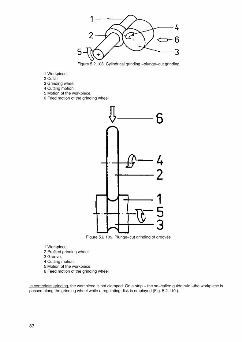
Figure 5.2.108. Cylindrical grinding −plunge−cut grinding
1 Workpiece,2 Collar3 Grinding wheel,4 Cutting motion,5 Motion of the workpiece,6 Feed motion of the grinding wheel
Figure 5.2.109. Plunge−cut grinding of grooves
1 Workpiece,2 Profiled grinding wheel,3 Groove,4 Cutting motion,5 Motion of the workpiece,6 Feed motion of the grinding wheel
In centreless grinding, the workpiece is not clamped. On a strip − the so−called guide rule −the workpiece ispassed along the grinding wheel while a regulating disk is employed (Fig. 5.2.110.).
83
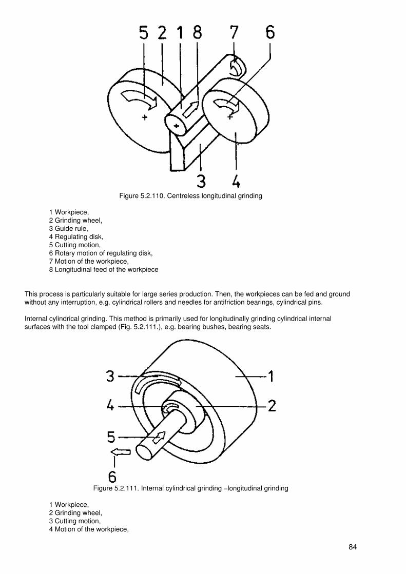
Figure 5.2.110. Centreless longitudinal grinding
1 Workpiece,2 Grinding wheel,3 Guide rule,4 Regulating disk,5 Cutting motion,6 Rotary motion of regulating disk,7 Motion of the workpiece,8 Longitudinal feed of the workpiece
This process is particularly suitable for large series production. Then, the workpieces can be fed and groundwithout any interruption, e.g. cylindrical rollers and needles for antifriction bearings, cylindrical pins.
Internal cylindrical grinding. This method is primarily used for longitudinally grinding cylindrical internalsurfaces with the tool clamped (Fig. 5.2.111.), e.g. bearing bushes, bearing seats.
Figure 5.2.111. Internal cylindrical grinding −longitudinal grinding
1 Workpiece,2 Grinding wheel,3 Cutting motion,4 Motion of the workpiece,
84

5 Longitudinal feed of the grinding wheel6 In−feed motion
Internal grooves are ground according to the plung−cut grinding process (Fig. 5.2.112.).
Figure 5.2.112. Internal cylindrical grinding − plunge−cut grinding
1 Workpiece,2 Grinding wheel,3 Groove to be ground,4 Cutting motion,5 Motion of the workpiece,6 Feed motion of the grinding wheel
In special machines, antifriction bearing rings are ground both by the method of centreless grinding and by theplunge−cut grinding process. This is particularly economical when high numbers of workpieces, e.g. large lots,have to be produced.
Abrasive cutting−off. Abrasive cutting−off on principle is plunge−cut grinding (Fig. 5.2.113.). For this purpose,very narrow wheels are used. The particularly high cutting speeds involved become possible because of thefact that the grinding wheels are provided with a wire skeleton or they are bonded by means of rubber.
Abrasive cutting−off is used especially in rolling mills for separating the rolled sections, in foundries forseparating of risers, and for separating hard materials, e.g. hard metals.
The process of abrasive cutting−off is also of importance to non−metals such as glass, ceramic materials androcks.
Figure 5.2.113. Abrasive cutting−off
85

1 Workpiece to be separated,2 Point of separation,3 Grinding wheel,4 Cutting motion5 Feed motion of the grinding wheel
Gear tooth grinding. The quality of a gear is mainly determined by the truth to shape of the tooth and the highsurface quality of the tooth profile. Therefore, gear teeth are ground by means of special−purpose machinesand special grinding tools.
In mass production, grinding worms are used in the generating process (Fig. 5.2.114.).
Figure 5.2.114. Gear tooth grinding
1 Gear,2 Grinding worm,3 Cutting motion,4 Rotary motion of the gear
Tool grinding. For sharpening tools, various grinding processes are used which are specially adapted to thetool and tooth shape. In many cases, tool grinding machines are required in order to achieve the specifiedaccuracy.
Summary:
Grinding is a process in which chips are detached from materials by bonded hard abrasive tools withgeometrically non−defined cutting edges.
Quite different tools and a great variety of grinding machines ensure that grinding can be used in a widefield for the improvement of the surface quality of workpieces and their accuracy to size, for separating, andfor sharpening tools.
5.2.11. Honing
Honing is defined as a finishing operating and a precision finishing process. It serves for the furtherimprovement of the truth to shape, accuracy to size and surface quality of pre−machined surfaces which haveto be finish−machined at least.
Means of work
Honing stones. The internal structure of honing stones is similar to that of bonded abrasives. They aremanufactured in different shapes and dimensions, adapted to the jobs in question.
Depending on the workpiece surface quality required, honing stones are made of special corundum or siliconcarbide with grain sizes from 0.32 to 0.014 mm which are bonded ceramically or by means of synthetic resins;
86

for superfinishing, graphite is added to the honing stones. In mass production, the use of honing stoneshaving a metallic basic body and a coat of diamond are particularly economical.
Honing tools. The honing sticks or stones are held by honing tools. The honing tool performs the necessarychip−detaching motion and ensures the pressure against the workpiece surface. The honing stones can beexchanged in the tool.
Honing machines. The high precision of honing calls for compact machines which are practically free fromvibrations and operate with high accuracy. The basic structure is different, depending on the shape of thesurface to be machined. Honing machines for internal cylinders (drilled holes) resemble column−type drillingmachines. The tool is accomodated in a spindle which rotates and can be moved up and down. Honingmachines for external cylinders resemble cylindrical grinding machines. In the place of the grinding wheel, oneor several honing tools are used. Honing machines for plane surfaces resemble flat grinding machines.
Procedure
The honing tool on the machine moves the honing stone on the workpiece surface with a contact pressure of0.1 to 1 MPa (megapascal). This contact pressure is used as chip−detaching force which removes very finechips. At first the peaks of the surface roughness are ground off and then the elevations are further abraded −the surface of the workpiece is levelled (Fig. 5.2.115.). As a consequence, more and more abrasive grains arecaused to act and the cutting force is distributed to more and more cutting edges. In this way, the force percutting edge is reduced more and more until it will become insufficient for the removal of chips.
Figure 5.2.115. Procedure of honing
1 Honing stone,2 Rough workpiece surface,3 Levelled workpiece surface,4 Contact pressure,5 Chip−detaching motion
This means that there is no longer any cutting action.
Application
By honing, peak−to−valley heights of 0.25 um can be achieved and in superfinishing of this method, of up to0.08 um. In the machining process before honing, allowances of anything between 0.02 and 0.04 mm must beobserved. For superfinishing, several honing passes have to be performed in which the abrasive grain of thetool used must be smaller from one pass to the other.
Honing of internal cylinders. The honing tool moves in the hole with a rotating cutting motion. The feed motionis effected over the entire length of the hole in axial direction. In−feed is effected by the contact pressure (Fig.5.2.116.).
87

Figure 5.2.116. Honing of internal cylinders
1 Workpiece,2 Honing tool,3 Honing stone,4 Springs for the contact pressure,5 Cutting motion,6 Feed motion
Internal cylinders of high accuracy are required for hydraulic cylinders, brake drums, connecting−rod bearingsas well as for cylinders of engines, pumps and compressors.
Honing of external cylinders. The honing stone is dressed on its working surface according to the desiredworkpiece diameter. The workpiece performs the rotating cutting motion. The feed motion is effected by thetool or the tools in the form of a reciprocating motion over the entire length of the cylinder to be machined. Forsuperfinishing, an oscillating motion is added.
In this motion, the tool oscillates up to 2000 times per minute over a width of 8 mm in axial direction (Fig.5.2.117.).
Figure 5.2.117. Honing of external cylinders
88

1 Workpiece,2 Honing stone,3 Honing tool,4 Cutting motion,5 Feed motion,6 Oscillary motion,7 Contact pressure
Gudgeon pins for fastening pistons to connecting−rods, bearing seats for precision parts and pistons forpumps, compressors, internal combustion engines and hydraulic cylinders are subjected to this manufacturingprocess.
Honing of plane surfaces. Honing of plane surfaces (Fig. 5.2.118.) is seldom used. It is applied to smallsurfaces such as found on measuring jaws, working surfaces of instruments and devices and sealing surfacesof taper casings.
Figure 5.2.118. Honing of plane surfaces
1 Workpiece,2 Honing stone,3 Honing tool,4 Cutting motion,5 Feed motion,6 Oscillary motion
Summary:
Honing is a finishing and superfinishing process and, in general, resembles grinding with a fine grain size.Special features are the particular chip−detaching motion and the setting of a contact pressure for thehoning stones. In order to achieve the high accuracies desired, precision tools and machines are required.
5.2.12. Lapping and Polishing
Lapping and polishing are fine finishing operation. By lapping dimensional accuracy, truth of shape andsurface quality are improved. Polishing reduces the roughness of the surface and produces a gloss effect.
Means of work
Lap material. The lap materials consist of a mixture of abrasive grains of the same size and various back−upor carrier materials. For polishing, the abrasives are called polishing agents or polishing paste.
Abrasive grains for lapping. The commonly used abrasives, namely, special corundum, silicon carbide andboron carbide as well as chromium oxide, iron oxide and diamond dust are used as lap material in the grainsizes from 0.12 mm to 0.007 mm.
89

Back−up materials. Back−up materials for this purpose are oils, benzole and kerosene in various mixtures.Commercial greases are used for the preparation of pastes.
Lapping machines. Depending on the shape of the workpiece and the particular lapping process, flat lappingmachines, hole lapping machines, vapour blasting machines and percussion lapping machines are used. Forpolishing, grinding machines with textile grinding wheels are used.
Procedure
Due to the kinetic energies applied, finest chips are removed from the workpiece surface by the abrasivegrains.
The kinetic energy is achieved by
− unconstrained counterparts moving against the workpiece (Fig. 5.2.119.)− oscillating tools − percussion lapping (Fig. 5.2.120.)− blasting of the lap material on the surface of the workpiece − vapour blasting (Fig. 5.2.121.)
Figure 5.2.119. Lapping with counterpiece
1 Workpiece,2 Lapping agent,3 Counterpiece,4 Lapping motion
Figure 5.2.120. Percussion lapping
1 Workpiece,2 Lap material,3 Oscillating tool
90

Figure 5.2.121. Lapping by blasting
1 Workpiece,2 Jet of the lap material,3 Blasting pipe
Application
The main purpose of lapping is the reduction of the roughness of finish−machined surfaces.
Depending on the size of the abrasive grain used, the following results can be achieved:
− coarse lapping 4 to 1 ?m
− fine lapping 0.4 to 0.15 ?m
− finest lapping 0.1 to 0.02 ?m
The peak−to−valley height obtained is also determined by the material machined and the kind of the lapmaterial.
When lapping with counterpart, the counterparts transmit their shapes to the workpiece with a depth of cut ofanything between 20 to 90 ?m.
For this purpose, the surfaces to be machined must already be precision finished. The material of thecounterparts is hard dense grey cast−iron.
Lapping with counterpart. Plane surfaces are lapped manually or mechanically on lapping disks. For thispurpose, the lap material is applied to the lap disk and the workpiece is placed on top.
Applying a slight pressure, the workpiece is moved reciprocatingly in all directions. Small sealing and contactsurfaces are subjected to this treatment.
Parallel surfaces are lapped between two lapping disks, usually on machines. The lapping disks rotate eitherat different speeds or in different directions. The workpieces are held by rotating lapping cages between thelapping disks (Fig. 5.2.122.).
91
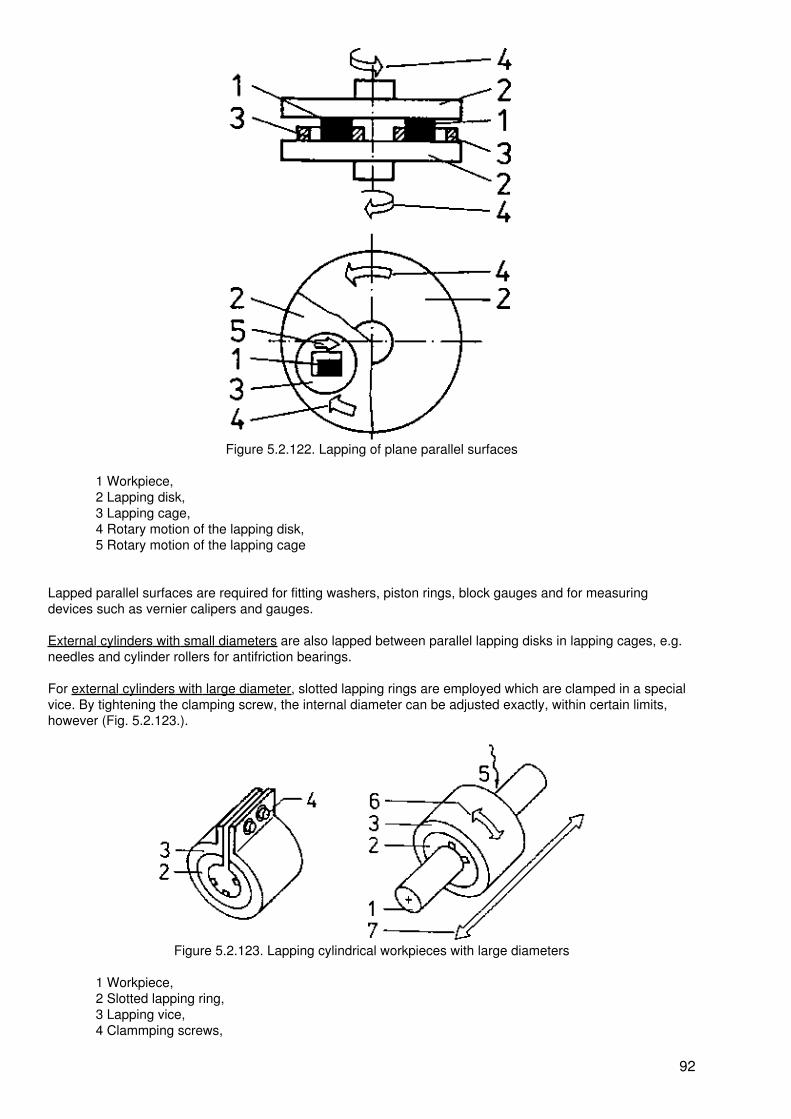
Figure 5.2.122. Lapping of plane parallel surfaces
1 Workpiece,2 Lapping disk,3 Lapping cage,4 Rotary motion of the lapping disk,5 Rotary motion of the lapping cage
Lapped parallel surfaces are required for fitting washers, piston rings, block gauges and for measuringdevices such as vernier calipers and gauges.
External cylinders with small diameters are also lapped between parallel lapping disks in lapping cages, e.g.needles and cylinder rollers for antifriction bearings.
For external cylinders with large diameter, slotted lapping rings are employed which are clamped in a specialvice. By tightening the clamping screw, the internal diameter can be adjusted exactly, within certain limits,however (Fig. 5.2.123.).
Figure 5.2.123. Lapping cylindrical workpieces with large diameters
1 Workpiece,2 Slotted lapping ring,3 Lapping vice,4 Clammping screws,
92
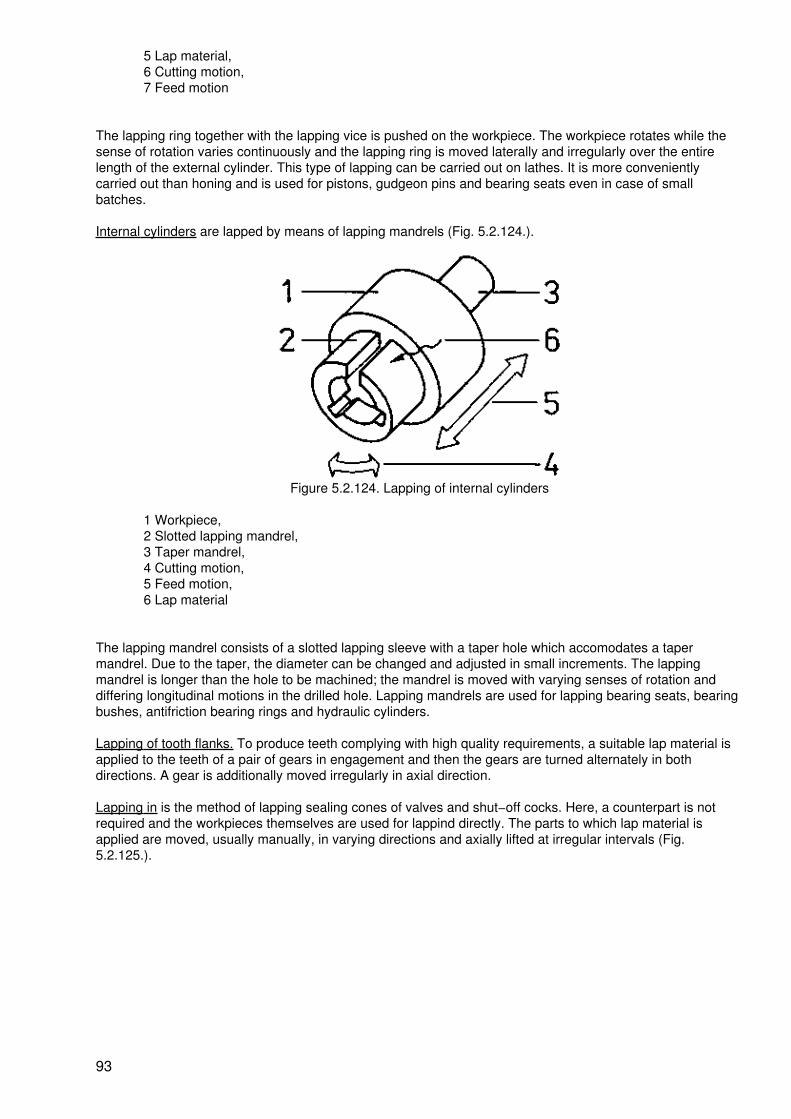
5 Lap material,6 Cutting motion,7 Feed motion
The lapping ring together with the lapping vice is pushed on the workpiece. The workpiece rotates while thesense of rotation varies continuously and the lapping ring is moved laterally and irregularly over the entirelength of the external cylinder. This type of lapping can be carried out on lathes. It is more convenientlycarried out than honing and is used for pistons, gudgeon pins and bearing seats even in case of smallbatches.
Internal cylinders are lapped by means of lapping mandrels (Fig. 5.2.124.).
Figure 5.2.124. Lapping of internal cylinders
1 Workpiece,2 Slotted lapping mandrel,3 Taper mandrel,4 Cutting motion,5 Feed motion,6 Lap material
The lapping mandrel consists of a slotted lapping sleeve with a taper hole which accomodates a tapermandrel. Due to the taper, the diameter can be changed and adjusted in small increments. The lappingmandrel is longer than the hole to be machined; the mandrel is moved with varying senses of rotation anddiffering longitudinal motions in the drilled hole. Lapping mandrels are used for lapping bearing seats, bearingbushes, antifriction bearing rings and hydraulic cylinders.
Lapping of tooth flanks. To produce teeth complying with high quality requirements, a suitable lap material isapplied to the teeth of a pair of gears in engagement and then the gears are turned alternately in bothdirections. A gear is additionally moved irregularly in axial direction.
Lapping in is the method of lapping sealing cones of valves and shut−off cocks. Here, a counterpart is notrequired and the workpieces themselves are used for lappind directly. The parts to which lap material isapplied are moved, usually manually, in varying directions and axially lifted at irregular intervals (Fig.5.2.125.).
93

Figure 5.2.125. Lapping a sealing cone
1 Lapping by turning,2 Lifting,3 Lowering when turning,4 Lap material
Polishing is effected by means of polishing agents and the counterparts used are polishing cotton or polishingdisks. The polishing agent is manually rubbed on the surface of the workpiece by means of polishing cotton incontinuously changing directions. Mechanically, rubbing is performed by disks of felt or by textile webs. Intoolrooms the engravings of moulds for casting or pressing, are polished; cooling channels, ornamentalobjects, enclosures, reflectors for headlamps and spot lights and dull coats of varnish are polished to achievea high gloss.
Percussion lapping. Percussion lapping is employed for the production of drilled holes and openings and forthe separating of very hard materials. The tool oscillates at a rate of 10 to 20 kilohertz (10,000 to 20,000oscillations per second) in the lap material and flings the abrasive grains against the workpiece with haighkinetic engergy. In this way, chips are removed from the workpiece (Fig. 5.2.120.).
The amount of chips detached is dependent on the material to be machined.
In accordance with the shape of the tool, holes and openings in nozzles, shear plates for shearing tools andjewel bearings for clocks and measuring instruments are made.
In addition, small moulds for initial shaping and forming can be produced. By means of narrow plate−liketools, hard bar stock, e.g. hard metal and ceramic material, are separated.
Percussion lapping is very important to the machining of glass.
Vapour blasting. Vapour blasting serves for the polishing of intricate external and internal shapes (Fig.5.2.121.). It is used for the polishing of engravings in initial shaping and forming tools. Parts of any shape canbe polished to a high gloss.
Summary:
Lapping is a method that is used for finishing and superfinishing of workpiece surfaces. In polishing, a highgloss is imparted to the parts. Due to the high kinetic energy of the sharp−edged abrasive grains, fine chipsare detached. The essential performance is the cutting motion effected over the whole surface with irregulardirections. Lapping is performed manually and with machines.
5.3. Erosion
There are various methods of erosion by which small and smallest particles are detached from theworkpieces. The coherence of the material is released by physical or chemical actions. The detached materialis changed.
94

5.3.1. Electroerosion
Electroeroding is the removal of material particles with the help of electrical discharges in the form of sparksor arcs.
Means of work
Electrodes. The tools for electroeroding, the electrodes, are made of well conducting metals (copper, brass,bronze, aluminium alloys, tungsten) in accordance with the job to be performed. Large electrodes are made ofgrey cast−iron.
Dielectric. A dielectric is a non−conducting liquid. For eroding, oil, kerosine or distilled water is used.
Eroding machines. Eroding machines are expensive special−purpose machines. They accomodate theelectrodes and the workpieces, perform the working operations and ensure the regulation of the electriccurrent with respect to the values specified.
Procedure
The workpiece (+) and the electrode (−) are connected to an electric direct current circuit (up to 40 V and upto 400 ampere) in a container with dielectric. When the electrode is approached to the workpiece, an electricaldischarge occurs in the form of sparks or arcs.
Figure 5.3.1. Procedure of electroerosion
1 Workpiece,2 Electrode,3 Dielectric,4 Spark discharge,5 Striking point of the discharge
At the point of discharge, small amounts of the material are molten or evaporated by virtue of the high energy(Fig. 5.3.1.).
By an oscillating motion of the electrode, an approach with discharge and repetition are ensured, At the sametime, the rinsing effect of the dielectric removes the material that is taken off.
Application
Electroeroding can only be used for the treatment of electrically conducting materials. Depending on thepower of the electric current the surface quality may be rough to fine finished.
Countersinking by eroding (Fig. 5.3.2.) is economical especially for the production of complicated engravingsof tools employed in initial shaping and forming.
95

Figure 5.3.2. Countersinking by eroding
1 Workpiece,2 Electrode,3 Dielectric,4 Feed motion,5 Oscillating motion
Boring by erosion (Fig. 5.3.3.) is used for the production of openings and holes in very hard materials, e.g.hardened steels and hard metals. Usually it is used for the production of nozzles.
Figure 5.3.3. Boring by erosion
1 Workpiece,2 Electrode,3 Dielectric,4 Feed motion,5 Oscillating motion
Cutting by eroding (Fig. 5.3.4.) is a method used for the separation of hard bar stock.
96

Figure 5.3.4. Cutting by eroding
1 Workpiece to be separated,2 Electrode,3 Dielectric,4 Feed motion,5 Oscillating motion,6 Rotary motion
Summary:
Eroding is the removal of material particles by electrical energy of discharge in the form of sparks and arcs. Itis used for countersinking, drilling and separating of hard conducting materials. Expensive special machinesare required for this purpose.
5.3.2. Elysing
The designation of the method of elysing is an abbreviation derived from condensing the term ofelectrolytically eroding. In the method of elysing, electrochemical and physical processes are involved.
Means of work
Electrodes, The shape−transmitting tools are made of copper, brass and steel individually in a way similar tothat found in electroeroding.
Elysing disks. For grinding by elysing, special grinding wheels are used which sometimes are coated withdiamond.
Electrolytes. Current conducting liquids such as lyes, acids and aqueous salt solutions attack the positivelyconnected workpiece when current is allowed to flow, thus effecting an electrochemical change of the surface.
Elysing machines. Elysing machines are special−purpose machines of various designs. They accomodateworkpiece and tool, perform the necessary operations of work, ensure the continuous feed of electrolytes, andenable the current to be regulated in the desired manner. Elysing plants. For some elysing operations, tankswith electrolytes are required which enable the work to be moved. Impregnating baskets and hoisting gear areadded to these plants.
Procedure
The workpiece (+) and the tool (−) are connected to a direct−current circuit (up to 20 V, up to 10,000 Ampere)in electrolytes or while electrolytes are continuously fed to the arrangement. Due to the action of the electriccurrent, the electrolyte is ionized and releases chemically active, aggressive ions. These ions cause chemicalreactions at the workpiece surface by which the material is transformed into oxides or salts. These products ofreaction only possess a low strength and can be removed simply by the rinsing action of the electrolyte or bygrinding.
97
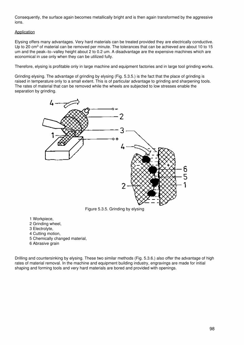
Consequently, the surface again becomes metallically bright and is then again transformed by the aggressiveions.
Application
Elysing offers many advantages. Very hard materials can be treated provided they are electrically conductive.Up to 20 cm3 of material can be removed per minute. The tolerances that can be achieved are about 10 to 15um and the peak−to−valley height about 2 to 0.2 um. A disadvantage are the expensive machines which areeconomical in use only when they can be utilized fully.
Therefore, elysing is profitable only in large machine and equipment factories and in large tool grinding works.
Grinding elysing. The advantage of grinding by elysing (Fig. 5.3.5.) is the fact that the place of grinding israised in temperature only to a small extent. This is of particular advantage to grinding and sharpening tools.The rates of material that can be removed while the wheels are subjected to low stresses enable theseparation by grinding.
Figure 5.3.5. Grinding by elysing
1 Workpiece,2 Grinding wheel,3 Electrolyte,4 Cutting motion,5 Chemically changed material,6 Abrasive grain
Drilling and countersinking by elysing. These two similar methods (Fig. 5.3.6.) also offer the advantage of highrates of material removal. In the machine and equipment building industry, engravings are made for initialshaping and forming tools and very hard materials are bored and provided with openings.
98
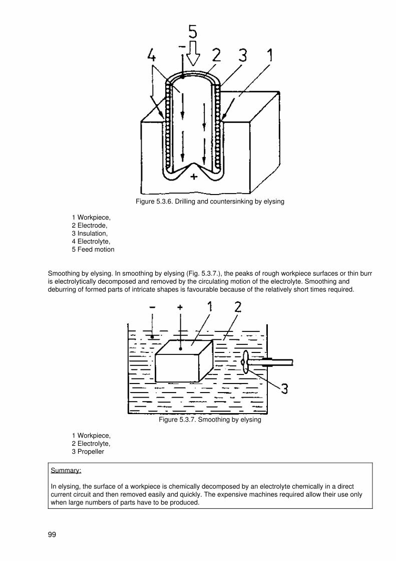
Figure 5.3.6. Drilling and countersinking by elysing
1 Workpiece,2 Electrode,3 Insulation,4 Electrolyte,5 Feed motion
Smoothing by elysing. In smoothing by elysing (Fig. 5.3.7.), the peaks of rough workpiece surfaces or thin burris electrolytically decomposed and removed by the circulating motion of the electrolyte. Smoothing anddeburring of formed parts of intricate shapes is favourable because of the relatively short times required.
Figure 5.3.7. Smoothing by elysing
1 Workpiece,2 Electrolyte,3 Propeller
Summary:
In elysing, the surface of a workpiece is chemically decomposed by an electrolyte chemically in a directcurrent circuit and then removed easily and quickly. The expensive machines required allow their use onlywhen large numbers of parts have to be produced.
99

5.3.3. Etching
Etching is a chemical removal of workpiece particles. Etching calls for the strict adherence to safety and workprotection regulations.
Means of work
Etchants. Chemically aggressive lyes and acids in different concentrations are used for etching.
Etchants are detrimental to health and aggressive against clothing and skin!
Etching baths. The etching means or etchants are kept, circulated and cleaned or renewed in special tanks ofacid−resistant and lye−resistant materials, taking strictest safety regulation into consideration.
Covering agents. Acid−resistant and lye−reistant varnishes and waxes and paraffin are required to stop offareas which shall not be attacked by etchants.
Procedure
When the etchants get into contact with the material, the latter is chemically attacked and decomposed. Theproducts of reaction obtained in this way, i.e. normally salts, are dissolved. At the points of contact, particles ofthe material are removed.
Application
Lettering. The surface of workpieces of metal or glass is covered by a thin layer of a covering agent. Theletters are scratched into this layer so that the covering agent is removed for the area of the letters. Whenthen an etchant is poured on the letters scratched into the agent, the material will be decomposed in theseplaces so that the lettering will apear as depressions (Fig. 5.3.8.).
Figure 5.3.8. Lettering by etching
1 Workpiece,2 Protective layer by covering agent,3 Letters without protective layer,4 Etchant,5 Etched letters that appear as depressions
Contour etching. Openings and depressions are produced according to the same method as that used forlettering. When allowing a longer time of action, the depth of the depression will be increased. The method ofcontour etching (sometimes also called chemical milling) is used for producing relief plates for letterpressprinting, parts of light−weight construction, and precision parts of limited size and complicated contours.
Polish−etching. The workpiece is provided with a thin film of covering agent. Consequently, the peaks of theroughness of the workpiece surface remain unprotected and are decomposed by the etchant applied (Fig.5.3.9.).
100

Figure 5.3.9. Polish−etching
1 Rough workpiece surface,2 Covering agent,3 Etchant,4 Etched surface
Summary:
Etching is a chemical method of removing particles from materials. By means of covering agents, points canbe marked on work surfaces where no action of the etchant should be carried out. The etchants which aredetrimental to health call for strictest safety regulations!
5.3.4. Flame Cutting
In flame cutting, the materials to be cut are heated so that their readiness to react is improved and then theyare changed and cut by chemical reactions.
Means of work
Cutting torch, A combustible gas and oxygen are mixed in cutting torches and, when leaving the torch nozzle,the mixture is burnt. This produces a high amount of heat. A further nozzles ensures the feeding of additionaloxygen.
Electrode holder and hollow electrodes. Between the electrode clamped in and guided by the electrode holderand the workpiece, an electric arc is produced. Through the hollow electroce, oxygen is blown.
Procedure
By the heat energy of the gas flame or the arc, the material is heated to the so−called ignition temperature.The ignition temperature is that temperature at which the material reacts with oxygen i.e. the temperature atwhich the material burns. When the ignition temperature is reached, the oxygen is blown on the heated pointof separation. The oxygen and the material react vigorously − oxides are brought about. Due to the blowingaction of the oxygen jet, the oxides produced are blown away,
Application
Flame cutting is used to cut mainly iron materials, The shoulder of the cuts is very rough and show hardenedand oxide crusts which call for reworking, Blanks are cut out of plates and stronger metal sheets which areused, e.g. for tank construction, steelwork and ship building. For the preparation of scrap of various shapes,flame cutting is required for cutting the larger parts into pieces that can be transported. In foundries, massiverisers and the like are cut during the cleaning of castings. Flame cutting can also be used for separatingsections, pipes and beams when the cutting edges need not be reworked or finished. Flame cutting can onlybe used when the ignition temperature is below the melting temperature of the material to be cut.
Control Questions
5.1. Why is it not possible to cut hard materials by means of wedges?
5.2. Why should plates of the specified thickness only be cut by means of hand−lever and machine shears?
101
5.3. Compare the main fields of application of wedge cutting and shearing!
5.4. Explain all angles and surfaces of lathe tools!
5.5. Explain the use of a few clamping accessories for turning!
5.6. Explain the difference between plain turning and surfacing!
5.7. Why is the method of conventional up−cut milling mainly used in cylindrical milling?
5.8. Explain the difference between up−cut milling and down−cut milling!
5.9. Explain the difference between planing and shaping !
5.10. What are the particulars to be observed in roughing of crusts of castings and crusts of forgings?
5.11. Quote three faults which should be avoided when grinding a twist drill!
5.12. Explain the structure of a twist drill!
5.13. What are the jobs for which centring drills have to be used?
5.14. What are the consequences when carelessly handling reamers?
5.15. Why is an allowance observed when drilling a hole that must be reamed?
5.16. Why is countersinking better than counterboring?
5.17. What are the advantages offered by preparing openings in workpieces by hand−saws?
5.18. What must be observed in any case when clamping hacksaw blades?
5.19. Explain the staggering of teeth of a broaching tool I
5.20. Why is the use of broaching restricted?
5.21. Explain the use of a surface plate!
5.22. Explain how the quality of a scraped surface is determined !
5.23. Substantiate the comprehensive work safety regulations for grinding!
5.24. Explain the differences between circumferential grinding and face grinding!
5.25. Explain the cutting motions of honing!
5.26. How is a surface finished by lapping?
5.27. Explain the process of electroeroding!
5.28. Describe the differences between electroeroding and elysing!
6. Manufacturing Method of Joining
Workpieces produced by the main groups of [...] s, namely, "initial shaping", "forming" and [...] ating" rarelyconstitute an object that is [...] for use. Mostly, several elements are [...] into components, sub−assembliesand [...] ts (Fig. 6.0.1.).
102

6.0.1. [...] in a crank
[...] cess of joining must be organized in such a [...] at the regulations of health, labour and [...] otection andsafety in force are strictly [...]ed and that the product complies with the [...] ments of serviceability.
[...] is a part of the assembly process. The [...] y process also includes the arranging, [...], feeding and testing(measuring). On the [...] land, connecting is a part of the joining [...].
While connecting deals with the mechanism of action in the point of connection, joining above all considersthe technological realization.
Keep in mind:
Joining is a main group of methods where the workpieces are produced by bringing together two or moreelements or components with shapeless matter (gases, liquids).
Table 6.1. shows a surfey of important methods of joining.
Table 6.1. Survey of the Methods of Joining
Joining by pressing on and in: − screwing and bolting
− keying
− clamping
− pressing
− pinning
− rivetting
− feather−key connection
Joining by initial shaping: − pressing in
103
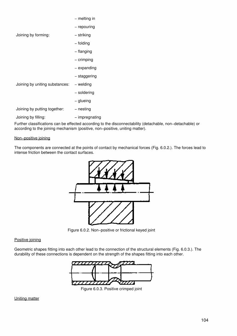
− melting in
− repouring
Joining by forming: − striking
− folding
− flanging
− crimping
− expanding
− staggering
Joining by uniting substances: − welding
− soldering
− glueing
Joining by putting together: − nesting
Joining by filling: − impregnating
Further classifications can be effected according to the disconnectability (detachable, non−detachable) oraccording to the joining mechanism (positive, non−positive, uniting matter).
Non−positive joining
The components are connected at the points of contact by mechanical forces (Fig. 6.0.2.). The forces lead tointense friction between the contact surfaces.
Figure 6.0.2. Non−positive or frictional keyed joint
Positive joining
Geometric shapes fitting into each other lead to the connection of the structural elements (Fig. 6.0.3.). Thedurability of these connections is dependent on the strength of the shapes fitting into each other.
Figure 6.0.3. Positive crimped joint
Uniting matter
104

The parts to be joined are fused together at their contact surfaces (forces of cohesion are acting) or theyadhere to one another (adhesive forces are acting) (Fig. 6.0.4.).
Figure 6.0.4. United matter in a glued joint
Cohesion
Force holding the smallest constituents (molecules) together.
In other words, molecular attraction by which the particles of a body (workpiece) are united throughout themass.
Adhesion
The sticking together of different substances at their boundary surfaces due to forces acting. They can actmechanically by the penetration of the connecting substance into depressions and pores of the surfaces of theparts to be joined.
6.1. Joining by Pressing On and In
6.1.1. Screwing
Frequently, parts of any material have to be connected in such a manner that they can be detached at anytime. Screwing or bolting are methods where the parts are connected by screws or by bolts and nuts andwasher (see Fig. 1.10.) or the parts themselves are provided with threads and screwed together.
Means of work
The basis of any screwed or bolted joint is the screw thread.
The types of screw threads can be grouped according to the profile of the threads:
− V−shaped thread (Fig. 6.1.1.)− knuckle thread (Fig. 6.1.2.)− acme thread (Fig. 6.1.3.)
Figure 6.1.1. V−shaped thread
Figure 6.1.2. Knuckle thread
Figure 6.1.3. Acme thread
105

Threads are produced by cutting or forming. When cutting internal threads, a method also known as tapping,at first the core diameter is drilled. Subsequently, a bevel is produced by countersinking (Fig. 6.1.4.).
Figure 6.1.4. Drilling and countersinking the core diameter
Then, the screw thread is cut in steps by means of taps (Fig. 6.1.5.).
Figure 6.1.5. Thread cutting
For screwings, screw−drivers are used as a tool (see Fig. 2.1.53.), also wrenches and spanners (see Figs.2.1.49 to 2.1.52.) or electric screw drivers and spanners in mass production.
Procedure
The screwed or bolted connection is brought about when the parts with similar internal and external threadsare joined by turning them against each other. This leads to a detachable, positive and non−positiveconnection.
In a directly screwed joint, the parts to be joined are directly provided with threads (Fig. 6.1.6.).
Figure 6.1.6. Direct screwed joint
If bolt, nut and washer are used for the production of the connection, this is called indirect screwing.Depending on the types of screws and bolts used, different connections can be obtained (Fig. 6.1.7. a to c).
Figure 6.1.7. Screwed and bolted joints
a Hexagon−head bolt and hexagon nut,b Fillister head screw with cross slot,c Countersunk screw with cross slot
106
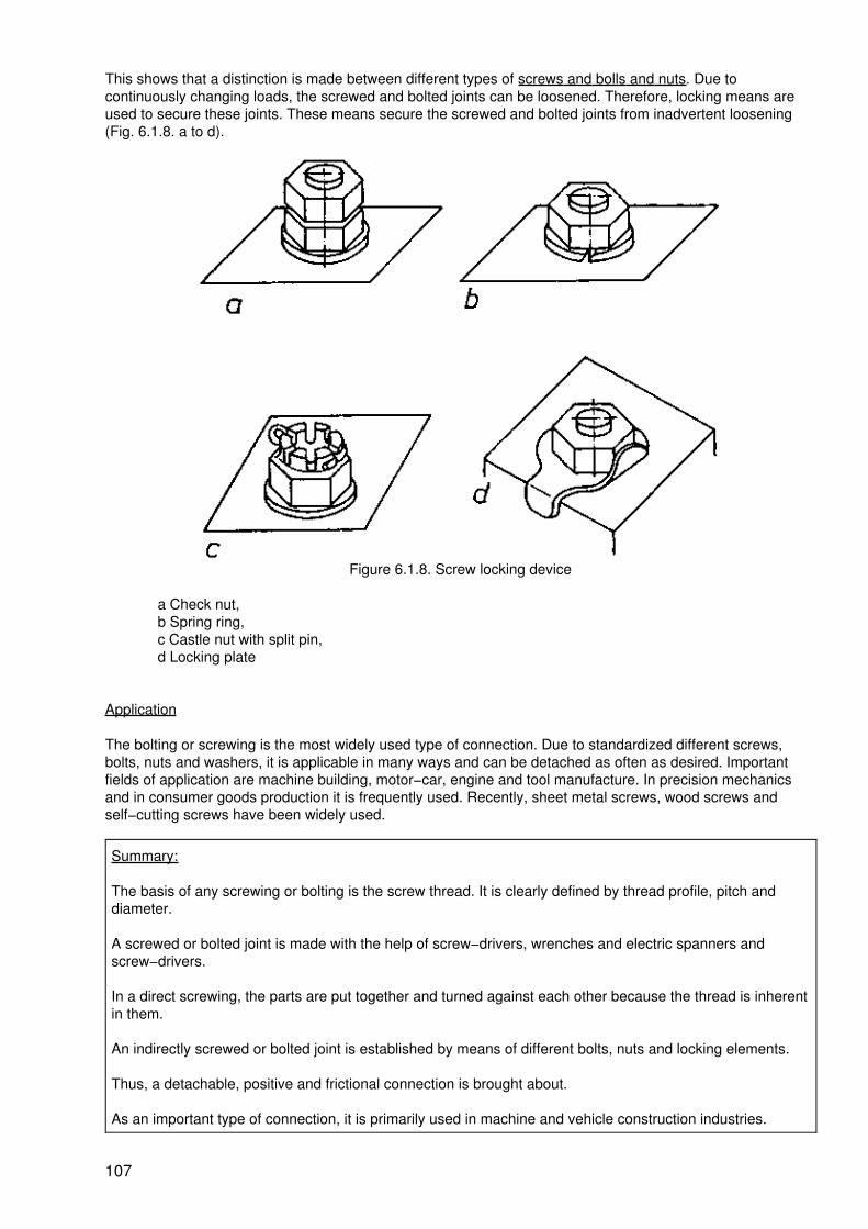
This shows that a distinction is made between different types of screws and bolls and nuts. Due tocontinuously changing loads, the screwed and bolted joints can be loosened. Therefore, locking means areused to secure these joints. These means secure the screwed and bolted joints from inadvertent loosening(Fig. 6.1.8. a to d).
Figure 6.1.8. Screw locking device
a Check nut,b Spring ring,c Castle nut with split pin,d Locking plate
Application
The bolting or screwing is the most widely used type of connection. Due to standardized different screws,bolts, nuts and washers, it is applicable in many ways and can be detached as often as desired. Importantfields of application are machine building, motor−car, engine and tool manufacture. In precision mechanicsand in consumer goods production it is frequently used. Recently, sheet metal screws, wood screws andself−cutting screws have been widely used.
Summary:
The basis of any screwing or bolting is the screw thread. It is clearly defined by thread profile, pitch anddiameter.
A screwed or bolted joint is made with the help of screw−drivers, wrenches and electric spanners andscrew−drivers.
In a direct screwing, the parts are put together and turned against each other because the thread is inherentin them.
An indirectly screwed or bolted joint is established by means of different bolts, nuts and locking elements.
Thus, a detachable, positive and frictional connection is brought about.
As an important type of connection, it is primarily used in machine and vehicle construction industries.
107

6.1.2. Keying
The effect of the wedge or key as a force−increasing element has been known for a long time (e.g. chisel,drive−fitted key, turning tool, milling cutter, etc.). The wedge and key can join parts by subjecting the mutuallyto stress (Fig. 6.1.9.).
Figure 6.1.9. Key joint
1 Key,2 Shaft,3 Hub
Today, keys are used primarily for shaft−hub connections of wheels or for centrically fastening tools (e.g. drillchucks, drills, milling cutters and the like).
Means of work
The grooves in shafts and hub are made by milling or shaping, i.e. by cutting processes. Groove and key musthave the same inclination. Keys are available as standardized structural elements in the form of sunk keys,drive−fitted keys or gib−head keys in different sizes.
Procedure
The key is placed into the prepared groove. By the displacing of the key (drive−fitted key) or of a matingelement (sunk key), groove and key are tightened. Thus, a detachable frictional connection is obtained.
Application
Longitudinal keys, usually called keys, are used for fastening wheels to axles and shafts.
Cotters connect linkage or bodies of revolution across the axle (Fig. 6.1.10.).
108

Figure 6.1.10. Cotter joint
Sleeve−type keys are used for centrically fastening tools (drills, milling cutters, reamers) Adjusting keys servefor adjusting bearing or guide clearances or for vertical adjustments.
Summary:
Keys are driven in prepared grooves between shaft and hub. They tighten mating parts and lead to adetachable frictional joint. Longitudinal keys, cotters, sleeve−type keys, tapers or adjusting keys are adaptedto the different conditions of use.
6.1.3. Feather−key Connection
In machine building, the feather key connection is used for connecting shaft and hub (gears, clutch parts)where an absolute truth of running is required (Fig. 6.1.11.).
Figure 6.1.11. Feather key joint
109

1 Feather key,2 Shaft,3 Hub
Means of work
The grooves for the accomodation of the feather keys are prepared by cutting operations. The shaft groove forstraight−face feather keys are milled by means of cylindrical or grooving cutters whereas shaft grooves forcrowned feather keys are milled by means of shank cutters or keyseating cutters.
The feather keys are adapted to the widely differing peculiarities of use.
Procedure
The feather keys are fitted into the groove of the shaft without any play. On the other hand, very little play isprovided in the groove of the hub. When the shaft rotates, the hub is carried along and torques aretransmitted. A detachable conjugate shaft−hub connection is produced. The axial displacement of the part tobe driven (gear) is either allowed (switching motion) or it must be prevented by other connections (e.g. pins,screws). Since the parts are not tightened against each other, perfectly true running is ensured.
Application
The feather key connection as a shaft−hub connection ensuring a high accuracy of true running if frequentlyused in machine building. It is used very often where the parts must be displaced axially for switching orindexing motions (speed−changing mechanism). If jerky and alternating loads are to be expected, shaft andsecondary bore are provided with a profile (Fig. 6.1.12.).
Figure 6.1.12. Profile shaft connection
Summary:
Feather keys (also known as fitting keys) are fitted into prepared grooves between shaft and hub. Theyprevent the turning of shaft and hub against each other. In this way, a detachable conjugate connection isproduced which is secured against twist. In axial direction, displacement is possible which can be used forcontrol or indexing motions.
The grooves for straight or round−ended or disk−type keys are produced by cutting operations such asmilling or shaping. For high jerky and changing loads, profile shafts are used.
110

6.1.4. Pinning
For securing parts in their position or for centring them, pins are frequently used (Fig. 6.1.13.).
Figure 6.1.13. Pinned joint
1 Pin
They are also used as a stop, for attaching springs and the like or for fastening components. There is a greatvariety of pins adapted to the different conditions of use. Grooved pins are frequently used.
Means of work
The necessary holes are drilled by means of a twist drill, i.e. by a cutting operation. When the pin is to befitted, the hole must be reamed to the desired size; for this purpose, reamers are required.
The pins are pressed into the drilled hole by means of a hammer or simple presses.
Pins are standardized in different designs. Generally, a distinction is made between cylindrical pins, taper pinsand grooved pins.
Procedure
The pin is pressed into the aligned holes of the parts to be joined together. Since the holes are drilled to a sizewhich is by about 2/10 mm smaller than the pin, the pin is fitted with an interference fit. The pin forces theparts to be joined into the desired position and retains them in this position. The joint produced is a detachableconjugate connection.
Frequently, the function of the pins is only the securing of the components in their location with respect toeach other and to ensure frequent loosening of the connection (Fig. 6.1.14.). For this purpose, the pin ispressed into one part while it is fitted into the other part with a very slight clearance.
Figure 6.1.14. Pins for securing the position
111
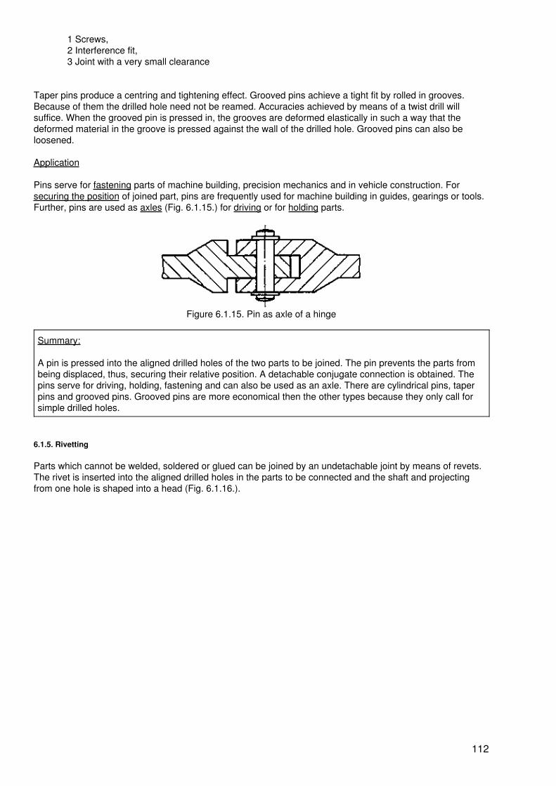
1 Screws,2 Interference fit,3 Joint with a very small clearance
Taper pins produce a centring and tightening effect. Grooved pins achieve a tight fit by rolled in grooves.Because of them the drilled hole need not be reamed. Accuracies achieved by means of a twist drill willsuffice. When the grooved pin is pressed in, the grooves are deformed elastically in such a way that thedeformed material in the groove is pressed against the wall of the drilled hole. Grooved pins can also beloosened.
Application
Pins serve for fastening parts of machine building, precision mechanics and in vehicle construction. Forsecuring the position of joined part, pins are frequently used for machine building in guides, gearings or tools.Further, pins are used as axles (Fig. 6.1.15.) for driving or for holding parts.
Figure 6.1.15. Pin as axle of a hinge
Summary:
A pin is pressed into the aligned drilled holes of the two parts to be joined. The pin prevents the parts frombeing displaced, thus, securing their relative position. A detachable conjugate connection is obtained. Thepins serve for driving, holding, fastening and can also be used as an axle. There are cylindrical pins, taperpins and grooved pins. Grooved pins are more economical then the other types because they only call forsimple drilled holes.
6.1.5. Rivetting
Parts which cannot be welded, soldered or glued can be joined by an undetachable joint by means of revets.The rivet is inserted into the aligned drilled holes in the parts to be connected and the shaft and projectingfrom one hole is shaped into a head (Fig. 6.1.16.).
112

Figure 6.1.16. Rivetted joint
1 Rivet inserted into a drilled hole,2 Rivet with heads
Means of work
The forming of the rivet shank is effected by means of a locksmith's hammer and special tools.
The latter include:
Rivetting set. The rivet and the parts to be joined are pressed together by the rivetting set (Fig. 6.1.17.).
Rivet header. The head of the rivet preshaped by the locksmith's hammer is finished by the rivet header (Fig.6.1.20.).
Dolly. This holding−up hammer accomodates the preliminarily shaped rivet head and enables the shaping ofthe driven head (Fig. 6.1.17.). For mass production, compressed air rivetting hammers or hydraulic rivettingmachines are employed.
Procedure
The rivet is inserted into the two prepared drilled holes so that the shaft end projects from one hole. Theshaping of the second rivet heat (drived head) is performed in the following way:
Compressing the rivet. The rivet in the aligned drilled holes is placed with its head on the dolly, Then, bothrivet and workpieces are compressed by means of the rivetting set. The compressive force is produced byhand or by a suitable press (Fig. 6.1.17.)
113
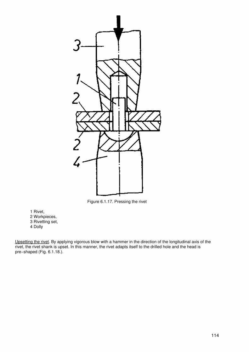
Figure 6.1.17. Pressing the rivet
1 Rivet,2 Workpieces,3 Rivetting set,4 Dolly
Upsetting the rivet. By applying vigorous blow with a hammer in the direction of the longitudinal axis of therivet, the rivet shank is upset. In this manner, the rivet adapts itself to the drilled hole and the head ispre−shaped (Fig. 6.1.18.).
114

Figure 6.1.18. Upsetting the rivet
1 Upset rivet shank
Pre−shaping the driven head. The preliminarily shaped head (driven head) is further pre−shaped. The blowsare applied round about the rivet head in an oblique manner without damaging the workpiece surface (Fig.6.1.19.).
115

Figure 6.1.19. Pre−shaping the driven head
1 Pre−shaped driven head
Finish shaping the driven head. By means of the rivet header, the driven head is properly shaped and thus therivet joint closed. The workpiece surface must not be damaged (Fig. 6.1.20.).
116

Figure 6.1.20. Finish shaping the driven head
1 Shaped driven head,2 Rivet header
This process is performed both in the hot and in the cold state. Countersunk−head rivets or hollow rivet headsare made in a similar manner (Fig. 6.1.21.).
The parts to be joined are pressed together between the two heads. This clamping action leads to thenon−positive or frictional condition of the joint. The rivet is subjected to tensile stress. The connectionestablished is non−detachable. When the load applied across the rivet axis becomes greater than theclamping action, the rivet will be subjected to shearing stresses.
117

Figure 6.1.21. Hollow rivet joint
1 Hollow rivet,2 Rivet header,3 Dolly
Application
Main fields of application are the industries constructing machines, boilers, vehicles, ships, and aeroplanesand steel construction. Metals, leather, cardboard, wooden plates, textiles and other materials are rivetted indifferent combinations. Today, rivetting has been replaced to a great extent by welding, soldering and glueing.Rivetting is used mainly for repairs of every description or in cases where welding, soldering and glueing arenot possible.
Summary:
The rivetted joint is a non−detachable, conjugate and partly frictional connection. By the operations
− compressing the rivet,− upsetting the rivet,− pre−shaping the driven head and
118

− finishing the driven head
a second rivet head is shaped; the parts are pressed together between the two heads. The tools requiredare hammer, rivetting set, rivet header and dolly. Button head rivets, countersunk−head rivets, hollow rivetsor flat rivets are adapted to the wide range of conditions of use.
Today, the rivet joint has been replaced to a great extent by welding, soldering and glueing. It is still used forrepairs and special fields of application.
6.1.6. Pressing
Parts to be joined which gear into each other are prepared with an oversize of the internal part and undersizeof the external part.
Figure 6.1.22. Pressed joint
The parts are joined together by pressing them with high forces or after a short−time enlargement or reductionof the dimensions with the help of the action of temperature (Fig. 6.1.22.).
Means of work
When the parts to be joined are only pressed together, the forces required are applied by hand, mechanicallyor hydraulically. In any case, the use of simple mechanical presses is favourable, too, because the parts mustnot be tilted. The application of some grease or oil prevents the uncalled−for cold welding of the parts. Assource of heat or coolant various media are used (Table 6.2.).
Table 6.2. Heat sources and coolants for pressing
Temperature Heat source/coolant
+ 700 °C gas and electric furnaces
+ 360 °C oil bath
+ 100 °C heating plate
− 70 °C dry ice (carbon dioxide snow)
− 190 °C liquid air
Procedure
A distinction is made between interference fit, shrink fit and expansion fit, depending on the type of joint to beproduced.
119

Interference fit is produced by pushing the external or internal part vigorously in place by hand or by means ofpresses.
Shrink fit is attained by heating the external part before fitting. When the part has cooled down, its diameter isagain reduced and, in this way, the connection established.
Expansion fit is obtained when the diameter of the internal part is reduced by supercooling. The connection isestablished after re−heating of the subcooled part.
Since the diameter of the internal part (shaft diameter) is larger than the diameter of the external part (holediameter), a uniform tension is brought about at the point which leads to a non−detachable non−positive,frictional connection (Fig. 6.1.23.).
Figure 6.1.23. Pressed joint
1 Diameter of drilled hole,2 Shaft diameter3 External part,4 Internal part,5 Parts pressed together
Application
The demand for exactly centric seat and true running of gears, shafts an antifriction bearings or clutch partscan be met without difficulty by interference fits. This connection is undetachable, however.
Summary:
Pressed connections are achieved in the form of interference fits, shrink fits or expansion fits. Pressed jointsare obtained by vigorously pressing together parts with oversize and undersize. For shrink fits, the externalpart is heated before joining to such a temperature that it will fit on the internal part. In contrast to this fit, theexpansion fit is obtained by supercooling the internal part before fitting in order to reduce its diameter, in anycase, a non−detachable non−positive joint is obtained.
6.2. Joining by Initial Shaping
6.2.1. Melting In
Parts of homogeneous or non−homogeneous metals and non−metals are molten together. In this way, slidebearing shells or bushes for cables or incandescent lamps are produced.
Means of work
Metals are molten in sand or die−casting moulds. The liquid metal is poured into the mould manually or bypressure. Glass is molten under a gas flame manually or mechanically.
Procedure
120
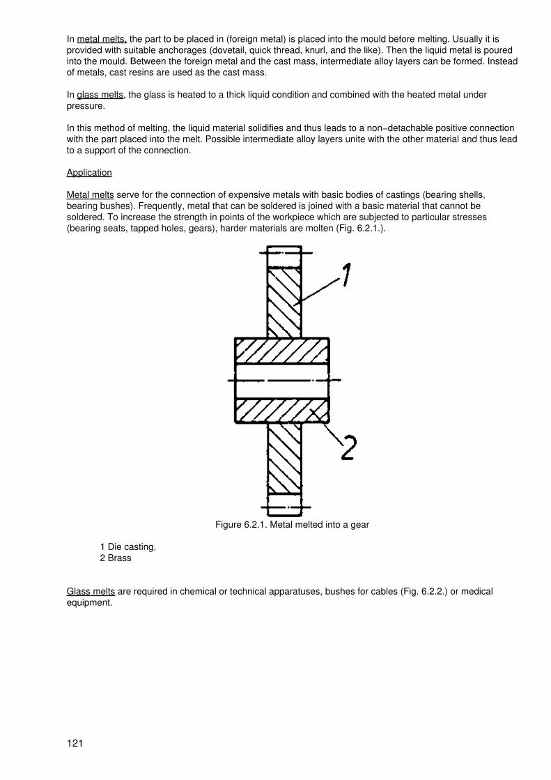
In metal melts, the part to be placed in (foreign metal) is placed into the mould before melting. Usually it isprovided with suitable anchorages (dovetail, quick thread, knurl, and the like). Then the liquid metal is pouredinto the mould. Between the foreign metal and the cast mass, intermediate alloy layers can be formed. Insteadof metals, cast resins are used as the cast mass.
In glass melts, the glass is heated to a thick liquid condition and combined with the heated metal underpressure.
In this method of melting, the liquid material solidifies and thus leads to a non−detachable positive connectionwith the part placed into the melt. Possible intermediate alloy layers unite with the other material and thus leadto a support of the connection.
Application
Metal melts serve for the connection of expensive metals with basic bodies of castings (bearing shells,bearing bushes). Frequently, metal that can be soldered is joined with a basic material that cannot besoldered. To increase the strength in points of the workpiece which are subjected to particular stresses(bearing seats, tapped holes, gears), harder materials are molten (Fig. 6.2.1.).
Figure 6.2.1. Metal melted into a gear
1 Die casting,2 Brass
Glass melts are required in chemical or technical apparatuses, bushes for cables (Fig. 6.2.2.) or medicalequipment.
121

Figure 6.2.2. Glass molten in
1 Wire,2 Glass body
Summary:
The method of melting−in is used for connecting homogeneous or non−homogeneous metals andnon−metals. The part to be included in the melt is placed in a mould for casting. The mould is filled with themolten liquid metal. A non−detachable connection of the positive type is produced while intermediate alloylayers may be formed. Bushes in glass bulbs are also produced by melting in.
6.2.2. Repouring
Pipes, rails, ropes or several parts of a large bulky workpiece are cast together by aluminothermic welding(Fig. 6.2.3.).
Figure 6.2.3. Pieces of rail connected by pouring
1 Joint
Means of work
Moulds surround the cross−section of the parts to be joined. The heat for melting the metal is obtained fromthe combustion of a thermit mixture. The thermit mixture consists of aluminium that is finely divided and ironoxide.
Procedure
The thermit mixture is ignited outside of the mould in a crucible. The temperature of ignition is about 1,100° C.Then, it burns automatically, forming slag, liquid iron and a reaction heat of about 2,400 °C. Subsequently,the thermit mass is poured into the mould. Due to the action of heat, the parts to be joined are molten at thesurfaces to be joined together and in this way welded with the thermit steel (Fig. 6.2.4.).
122

Figure 6.2.4. Rail in a mould for aluminiothermic welding
1 Crucible,2 Slag,3 Melt,4 Closure,5 Mould,6 Rail
The slag can be beaten off after removing the mould. An undetachable connection is obtained.
Application
Parts of the same metal but different cross−sections such as pipes, rails, wire ropes are joined together (Fig.6.2.5.).
Figure 6.2.5. Pieces of pipe joined by pouring
1 Pieces of pipe,2 Joint
Very large workpieces frequently are welded together of individual parts at the site of operation.
Summary:
123
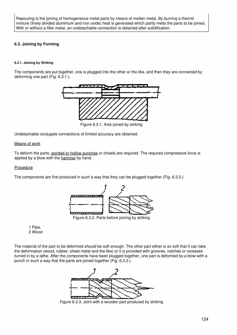
Repouring is the joining of homogeneous metal parts by means of molten metal. By burning a thermitmixture (finely divided aluminium and iron oxide) heat is generated which partly melts the parts to be joined.With or without a filler metal, an undetachable connection is obtained after solidification.
6.3. Joining by Forming
6.3.1. Joining by Striking
The components are put together, one is plugged into the other or the like, and then they are connected bydeforming one part (Fig. 6.3.1.).
Figure 6.3.1. Axle joined by striking
Undetachable conjugate connections of limited accuracy are obtained.
Means of work
To deform the parts, pointed or hollow punches or chisels are required. The required compressive force isapplied by a blow with the hammer by hand.
Procedure
The components are first produced in such a way that they can be plugged together (Fig. 6.3.2.).
Figure 6.3.2. Parts before joining by striking
1 Pipe,2 Wood
The material of the part to be deformed should be soft enough. The other part either is so soft that it can takethe deformation (wood, rubber, sheet metal and the like) or it is provided with grooves, notches or recessesturned in by a lathe. After the components have been plugged together, one part is deformed by a blow with apunch in such a way that the parts are joined together (Fig. 6.3.3.).
Figure 6.3.3. Joint with a wooden part produced by striking
124

1 Pipe,2 Wood
An undetachable conjugate connection is obtained.
Application
Joints which have not to comply with requirements regarding torsional strength, centric position and durabilitysuch as bearing and hinge pins, springs and brushes are made in this way. The connection of flat or roundsheet metal parts is also possible in this way.
Summary:
Components plugged together are joined by means of blows with a punch. This connection should only beused for limited requirements.
6.3.2. Folding
Rigid connections of parts of sheet metal can be produced by folding. The two edges of the sheets are bentover several times. By placing a rubber tape or a layer of an adhesive into the fold or by subsequentlysoldering, leak−proof joints can be obtained, e.g. for containers.
Means of work
The tools used are bending tools on folding machines are folding iron and hammer for manually folding.
Procedure
The edges of the sheet metal parts placed opposite to each other and perfectly parallel are first pre−shapedso that they can be hooked into each other (Fig. 6.3.4.).
Figure 6.3.4. Pre−shaped folded parts
After hooking into each other, the fold is compressed (Fig. 6.3.5.)and cranked (Fig. 6.3.6.). An undetachablepositive joint is produced.
Figure 6.3.5. Compressed fold
Figure 6.3.6. Cranked fold
If larger forces have to be taken up by the fold, it can be folded over several times.
For particular purposes, indirect folds with the help of a ledge (Fig. 6.3.7.) and angular folds (Fig. 6.3.8.) canbe produced.
125
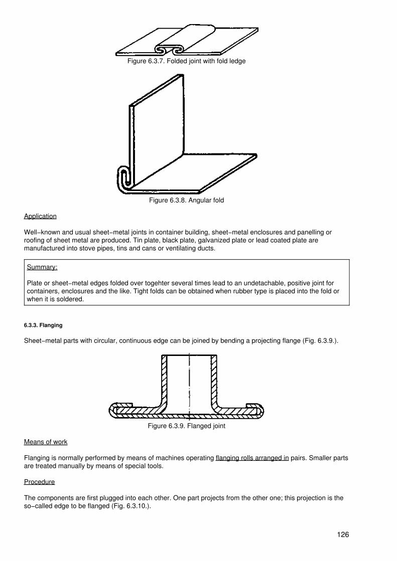
Figure 6.3.7. Folded joint with fold ledge
Figure 6.3.8. Angular fold
Application
Well−known and usual sheet−metal joints in container building, sheet−metal enclosures and panelling orroofing of sheet metal are produced. Tin plate, black plate, galvanized plate or lead coated plate aremanufactured into stove pipes, tins and cans or ventilating ducts.
Summary:
Plate or sheet−metal edges folded over togehter several times lead to an undetachable, positive joint forcontainers, enclosures and the like. Tight folds can be obtained when rubber type is placed into the fold orwhen it is soldered.
6.3.3. Flanging
Sheet−metal parts with circular, continuous edge can be joined by bending a projecting flange (Fig. 6.3.9.).
Figure 6.3.9. Flanged joint
Means of work
Flanging is normally performed by means of machines operating flanging rolls arranged in pairs. Smaller partsare treated manually by means of special tools.
Procedure
The components are first plugged into each other. One part projects from the other one; this projection is theso−called edge to be flanged (Fig. 6.3.10.).
126

Figure 6.3.10. Parts to be joined plugged into each other
By bending the edge, the position of the components is fixed with respect to each other (Fig. 6.3.11.). Anundetachable positive joint is produced.
Figure 6.3.11. Flanged joint with bent edge
The border can be folded over inwards or outwards (Fig. 6.3.12.).
Figure 6.3.12. Flange bent over outwards
By placing rubber or other elastic materials into the fold, leakproof flanged connections can be obtained.Hollow rivets can also be included in a flanged connection (see Fig. 6.1.2.1.).
Application
Connections of sheet−metal parts with circular borders, connections of mounts of lenses; settings, of parts ofglass (e.g. torch lamp reflectors) or other materials. The flanged joint is also useful for sheet−metal packings.Hollow rivets also show a border that is flanged.
127
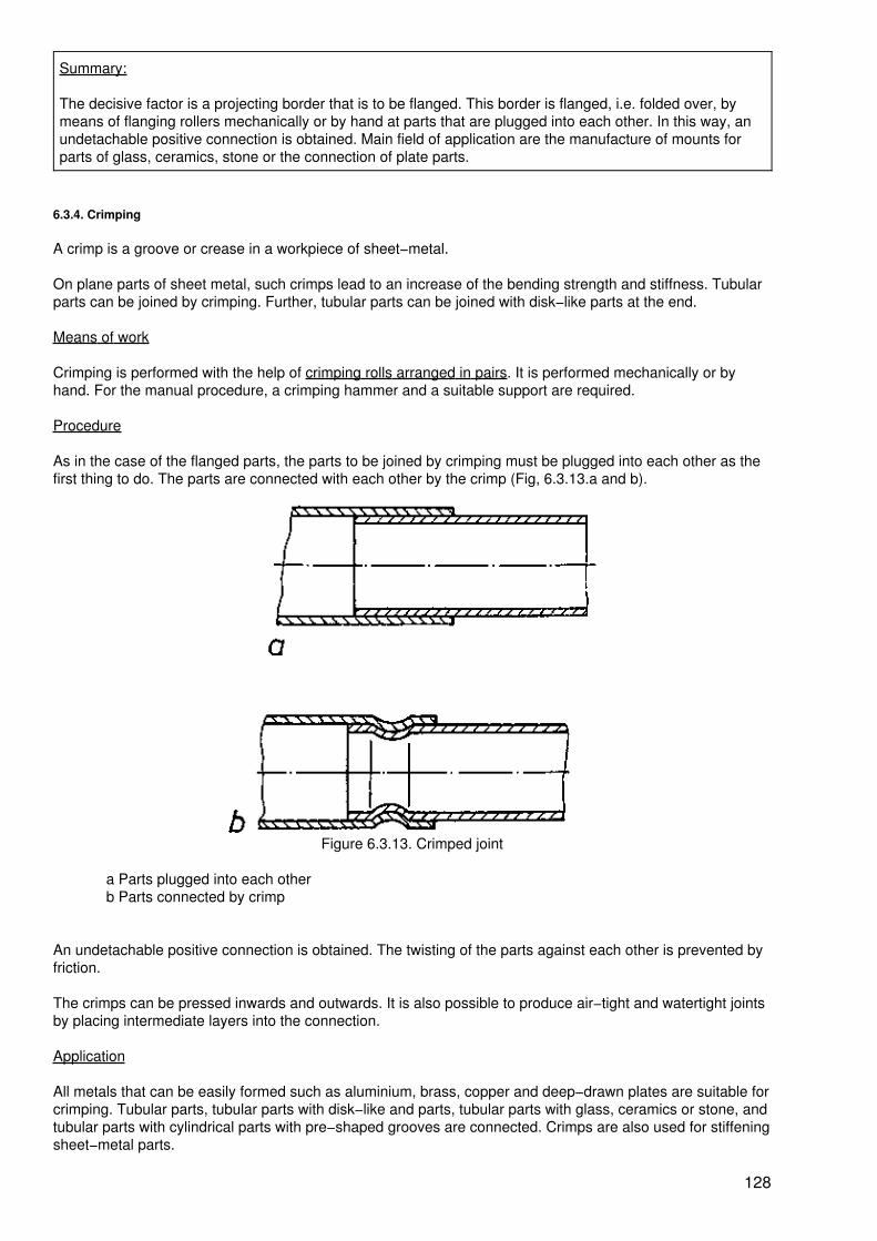
Summary:
The decisive factor is a projecting border that is to be flanged. This border is flanged, i.e. folded over, bymeans of flanging rollers mechanically or by hand at parts that are plugged into each other. In this way, anundetachable positive connection is obtained. Main field of application are the manufacture of mounts forparts of glass, ceramics, stone or the connection of plate parts.
6.3.4. Crimping
A crimp is a groove or crease in a workpiece of sheet−metal.
On plane parts of sheet metal, such crimps lead to an increase of the bending strength and stiffness. Tubularparts can be joined by crimping. Further, tubular parts can be joined with disk−like parts at the end.
Means of work
Crimping is performed with the help of crimping rolls arranged in pairs. It is performed mechanically or byhand. For the manual procedure, a crimping hammer and a suitable support are required.
Procedure
As in the case of the flanged parts, the parts to be joined by crimping must be plugged into each other as thefirst thing to do. The parts are connected with each other by the crimp (Fig, 6.3.13.a and b).
Figure 6.3.13. Crimped joint
a Parts plugged into each otherb Parts connected by crimp
An undetachable positive connection is obtained. The twisting of the parts against each other is prevented byfriction.
The crimps can be pressed inwards and outwards. It is also possible to produce air−tight and watertight jointsby placing intermediate layers into the connection.
Application
All metals that can be easily formed such as aluminium, brass, copper and deep−drawn plates are suitable forcrimping. Tubular parts, tubular parts with disk−like and parts, tubular parts with glass, ceramics or stone, andtubular parts with cylindrical parts with pre−shaped grooves are connected. Crimps are also used for stiffeningsheet−metal parts.
128

Summary:
By shaping a crimp into tubular sheet−metal parts, joints can be produced with the help of crimping rolls. Forthis purpose, the parts to be joined are plugged into each other. An undetachable positive connection isobtained. The tububar part can be joined with parts which already have a groove, consist of elastic material,are also a tubular part or represent a disk−like end cover.
6.3.5. Expanding
Tubular parts can be expanded, that is to say, the external diameter and the internal diameter are increased.This operation is also known as flaring. In this way, tubular parts can be fastened (Fig. 6.3.14.).
Figure 6.3.14. Pipe expanded on two sides
Means of work
Tools for rolling, pressing and bulging are required. These are taper rolls, pressing rolls or pressing steels.Expanding or flaring is effected on machines (e.g. lathes) or manually.
Procedure
The tube is expanded in the joined condition. Flares are produced on both sides so that the parts to be joinedcannot be detached. An undetachable positive joint is produced (Fig. 6.3.14.).
When the tube is totally expanded so that it is fitted firmly in the hole of the other part, a connection that canbe loosened under certain conditions and which is non−positive is obtained (Fig. 6.3.15.).
Figure 6.3.15. Non−positive joint by expanding
Application
129

Joints are produced of pipes with holders or tubular parts with parts to be incorporated in heating andventilating systems.
Summary:
When tubular parts are expanded in certain portions, undetachable positive connections are produced. Thisconnection is due to the fact that the part to be incorporated is fitted between the expanded portions so thatit cannot be loosened again.
6.3.6. Staggering
One part to be joined is provided with lugs of a pliable material (sheet metal). The other part has openings intowhich the lugs perfectly fit. The parts are joined by folding over the lugs or by twisting them (Fig. 6.3.16.).
Figure 6.3.16. Plates joined by folding staggered lugs
Means of work
The lugs and openings are usually made by means of shears. Joining is performed by means of tongs andhammer manually.
Procedure
For producing a direct connection, the parts are plugged into each other. Then the lugs are bent over ortwisted. In this way a connections is produced that is positive and can be loosened under certain conditions.
This joint can be produced in flat parts placed one upon the other or in parts arranged perpendicularly to eachother (Fig. 6.3.17. a and b).
The connection by split pins is included in this procedure (Fig. 6.3.18.).
Figure 6.3.17. Flat parts joined by staggered lugs
a Prepared parts,b Parts joined by staggered lugs
130
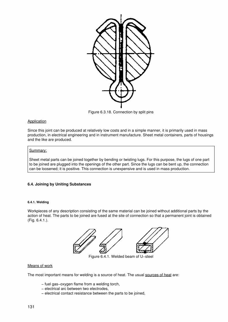
Figure 6.3.18. Connection by split pins
Application
Since this joint can be produced at relatively low costs and in a simple manner, it is primarily used in massproduction, in electrical engineering and in instrument manufacture. Sheet metal containers, parts of housingsand the like are produced.
Summary:
Sheet metal parts can be joined together by bending or twisting lugs. For this purpose, the lugs of one partto be joined are plugged into the openings of the other part. Since the lugs can be bent up, the connectioncan be loosened; it is positive. This connection is unexpensive and is used in mass production.
6.4. Joining by Uniting Substances
6.4.1. Welding
Workpieces of any description consisting of the same material can be joined without additional parts by theaction of heat. The parts to be joined are fused at the site of connection so that a permanent joint is obtained(Fig. 6.4.1.).
Figure 6.4.1. Welded beam of U−steel
Means of work
The most important means for welding is a source of heat. The usual sources of heat are:
− fuel gas−oxygen flame from a welding torch,− electrical arc between two electrodes,− electrical contact resistance between the parts to be joined,
131

− electron beam or plasma jet.
Frequently, the oxygen of the air enters into an undesired combination with the workpiece under the action ofheat (oxidation).
The following possibilites of protection against the atmospheric oxygen are given:
− protective gases (inert gases, CO2),− covering by powder,− copper bar covering,− slag formation.
Frequently, the weld seam must be formed by a homogeneous filler metal. The filler metal is used in thefollowing form:
− welding wire,− welding electrodes,− strip electrodes.
Further necessary means of work may be:
− gas production plant,− welding current generator,− electrodes,− clamping devices.
Procedure
The factors of "heat", "pressure" and "filler metal" determine the welding process. In fusion welding, thesource of heat melts the parts to be joined locally. With (or without) the filler metal, a weld seam is formedwhich after solidification is an undetachable connection (Fig. 6.4.2.).
Figure 6.4.2. Fusion welding (backhand welding process)
1 Workpiece,2 Welding torch.3 Filler metal
In pressure welding, an undetachable connection of two individual parts of homogeneous material is produced
132

by heat and pressure or pressure only. Frequently, the parts to be joined are pressed together with great forcewhile they are electrically heated by the action of the contact resistance (Fig. 6.4.3.).
Figure 6.4.3. Pressure welding (spot welding)
1 Workpiece,2 Dopper electrode
Shape, strength and appearance of the joint are determined by the joint of the metals to be joined, the shapeof the groove and the weld seam (Table 6.3.).
Table 6.3. Joint of the metals to be welded, welding groove and welding seam
Joint Shape of groove Welding seam
Butt−type joint plain butt weld
V weld
flange weld
Parallel joint edge joint weld
133

edge grooved weld
T Joint fillet weld
Corner joint (TB 6.3./19.) corner seam
Application
Welds are frequently the most economical and durable joints. They call for a high qualification of the workerand for relatively expensive and comprehensive means of work. Welding is subject to special safetyregulations.
Only the same materials can be welded together. Steel, copper, aluminium, cast−iron and alloys are welded.Plastics (thermoplastics) and glass can also be welded.
Very different materials, welded constructions and material thicknesses call for a great variety of specialwelding processes (Table 6.4.).
Table 6.4. Classification of the most important welding processes
Weldinggroup
Welding process Variant Shortdesignation
Fusionwelding
gas welding G welding
electric arcwelding
manual arc welding arc welding
submerged arc welding
inert−gasshielded
TIG welding
arcwelding
MIG welding
CO2−shieldedarc welding
134

electroslag welding
Pressure welding resistance forgewelding
spot welding
seam welding
Gas welding
The fuel gas−oxygen flame used as the source of heat is produced by a welding torch. The fuel gas is ethin(C2H2). Temperatures up to 3,000 °C are generated. The source of heat melts the workpiece and the fillermetal locally. The liquid filler metal fills the welding groove and, after solidification, forms the weld seam (Fig.6.4.4.).
Figure 6.4.4. Gas welding (leftward welding technique)
1 Workpiece,2 Welding torch,3 Filler metal
This process is employed for repair welding operations and for plates of steel, copper and aluminium. It isexclusively performed by hand.
Manual arc welding (electric welding)
The arc is formed between an electrode and the workpiece material when a current source is applied. Theelectrode takes the form of the rod−shaped filler metal (Fig. 6.4.5.).
Figure 6.4.5. Electric arc welding
1 Workpiece,2 Filler metal in the form of an electrode
A welding temperature of up to 4,000 °C is produced and intense light radiation emitted (goggles must beworn). The high temperature causes the parts to be joined and the electrode in the welding point to be fused.The melting electrode fills the welding groove and forms the weld seam. Since arc welding can be well
135

automated, manual arc welding is primarily used for designs of intricate shape, short weld seams, for repairand assembly welding operations of almost all metals.
Submerged−arc welding
In essence, this process resembles electric welding. The arc which enables the fusing of the parent metal andthe melting of the electrode burns under a layer of powder (Fig. 6.4.6.). The powder consists of a mixture ofminerals and metal.
It melts partly, thus forming a slag layer which protects the welding site from the atmospheric oxygen andretains the weld liquid for a prolonged time. Therefore, the weld pool must be protected. Submerged−arcwelding is used for the production of thicker and longer weld seams and for a high deposition efficiency. Sincethe arc is not visible, it is performed semi−automatically or fully automatically.
Figure 6,4.6. Submerged−arc welding
1 Workpiece,2 Filler metal in the form of an electrode,3 Feeding the welding powder,4 Support of the weld pool
Tungsten−arc inert−gas welding
The arc burns between a non−melting tungsten electrode and the workpiece. As a protection against theatmospheric oxygen, argon is conducted over the welding point as an inert gas. The filler metal is additionallyfed in the form of a welding wire. This welding process is primarily performed manually with the help of awelding torch (Fig. 6.4.7.). This welding process is also suitable for repair operations especially for rootpasses and spot welding.
Figure 6.4.7. Tungsten−arc inert−gas welding (TIG welding)
1 Workpiece,2 Welding torch,
136

3 Tungsten electrode,4 Filler metal,5 Argon protective gas
Metal−arc inert−gas welding process
The arc burns between the melting metallelectrode and the workpiece. Argon is the inert gas used. The fillermetal is the electrode in the form of welding wire (Fig. 6.4.8.). This welding process is particularly suitable forall grades of steel and many non−ferrous metals. It can produce very clean weld seams and is performed fullyautomatically and semi−automatically.
Figure 6.4.8. Metal−arc inert−gas welding process (MIG process)
1 Workpiece,2 Welding torch,3 Filler metal in the form of an electrode (welding wire),4 Argon protective gas
Gas−shielded arc welding with CO2
The arc burns between a melting wire electrode and the workpiece. As protective gas, the less expensivecarbon dioxide (CO2) is used. This process is similar to the metal−arc inert−gas welding (Fig. 6.4,9.). It isreadily automated; besides fillet welds and butt welds, spot welding can be performed.
137

Figure 6.4.9. CO2 gas−shielded are welding
1 Workpiece,2 Welding torch,3 Filler metal in the form of an electrode (welding wire)
Spot welding
Spot welding is a resistance forge welding process The parts to be joined (e.g. sheet metal) are pressedtogether in a succession of spots by pin−like copper electrodes. The electric contact resistance leads toheating up to a tough−liquid spot−like condition. Several spot welds arranged side by side or one after theother form the joint (Fig. 6.4.10.).
The pressure is generated hydraulically or mechanically. The process is performed mechanically and, with thehelp of welding pliers, by hand. It is used for joining plates placed one upon the other, which are perfectlyplane, and especially in automotive engineering and in the construction of containers of every description.
Figure 6.4.10. Electric resistance spot welding
1 Workpiece,2 Copper electrode
Summary:
Welding is a process of joining by which homogeneous materials are joined together with the help of heat(fusing welding) of pressure and heat (pressure welding) with or without a homogeneous filler metal. Thejoint produced is non−detachable. Sources of heat are fuel gas−oxygen flame, electric arc or electric contact
138

resistance.
As a protection against the atmospheric oxygen, inert gas, carbon dioxide, powder, copper bars, and slagare used. Further, gas generator, welding current generator, electrodes and clamping devices are requiredas means of work.
The weld is determined by the joint, the shape of the welding groove and the type of the seam desired. Theobservance of the relevant safety regulations for welding is of particular importance. These regulations coverhealth, labour and fire protection.
It is absolutely necessary to observe these regulations strictly in the interest of the safety of the workers.
6.4.2. Soldering and Brazing
Metallic workpieces can be joined together with the help of a molten metallic filler material (solder). Themolten solder joins the workpieces by adhesion after solidification.
The solder has a considerably lower melting point than the workpieces. This means that the workpieces arenot molten.
Means of work
For melting the solder, the following sources of heat are used:
− electrically heated soldering copper,− fuel gas−oxygen flame from a torch,− salt bath heated by flames,− solder bath heated by flames,− fuel gas−oxygen flame in a furnace.− inductively supplied high−frequency energy.
Depending on the working temperature and the strength of the joint, the following solders are used:
− tin−lead solders for working temperatures below 300 °C,
− mixed solders with different additions of the metals of cadmium, bismuth, silver, zinc andindium at 300 °C,
− copper solders for working temperatures above 800 °C,
− silver solders with different additions at about 700 °C,
− nickel solders for temperatures about 1,000 °C and high strength,
Solders are available in the form of rods, wires, blocks, grains and foil.
To remove the oxide layer from the parts to be joined and to improve wetting, the following fluxes are used:
− zinc chloride solutions of which residues remaining after soldering must be removed in anycase,
− colophonies (pine resins) and colophony solutions,
− boron compounds for temperatures above 700 °C.
Fluxes are available in the form of a liquid, paste, powder or in connection with the solder.
139

Further, the following means of work may be required:
− soldering gun with resistance−heated conductor loop,− tub with salt or solder bath,− transport devices,− clamping devices.
Procedure
The parts to be joined must be of metal or their surfaces must be metallized (e.g. circuit boards). The solder isalways a metal. At first the area of the joint is cleaned mechanically or chemically. After heating to the workingtemperature, the flux is applied. It removes oxide layers still present, prevents any new formation of them andfacilitates wetting with solder. After the application of solder, it will melt and flow into the groove of the parts tobe joined. After cooling down, the solder adheres to the two workpieces. A connections is established that canbe loosened under certain conditions. The joint can be loosened after heating to the melting temperature ofthe solder. The actual technology is dependent on the soldering process used. The joint covers the solderinggap and soldering groove and the shape of the soldered seam (Table 6.5.).
Table 6.5. Joint, gap or groove in soldering
Shapeofjoint
View Gap orgroove
Distance
Butt joint square groove smaller than 0.5 mm
V groove greater than 0.5 mm
double−V groove greater than 0.5 mm
Lapped joint gap smaller than 0.5 mmLength of overlap= 3× thicknessof sheet metal
T joint gap smaller than 0.5 mm
Application
Soldering is the joining of metallic workpieces or such with metallized surfaces where, due to thetemperatures involved, structural transformations, residual stresses after soldering and distortions must notoccur. In case of lower strength, density and electrical conductivity of small parts, sheet metals and hardlyaccessible points soldering is used. It is further employed for parts susceptible to heat and stresses inprecision mechanics and electrical engineering. A wide field of application are electrically conducting joints inelectrical engineering and electronics and their mass productions.
140

On the basis of different sources of heat and technologies, a great variety of soldering processes has beendeveloped (Table 6.6.)
Table 6.6. Classification of the most important soldering processes
Heatsource
Process Variant
Soldering bit bit soldering electric soldering iron
Fuel−gas oxygen flame flame soldering soldering lamp
Heated bath bath soldering dip soldering
Heated furnace furnace brazing chamber furnace brazing
Electric energy electric soldering induction soldering, induction brazing
Friction friction soldering
According to the working temperature, a distinction is made between:
− soft soldering at an operating temperature below 450 °C (about 260 to 300 °C),
− brazing (hard soldering) at an operating temperature above 450 °C (between 700 and1,000 °C).
Bit soldering
A soldering bit of copper which is heated by fire, gas or electrical energy is used as source of heat. Thesoldering bit is applied with its tip to the soldering point. In this way, it heats the joint to be made to a workingtemperature of about 400 °C. After addition of the flux and the melting of the solder, the latter runs into thesoldering gap and connects the two parts to be joined after solidification (Fig. 6.4.11.).
This method of soft soldering is employed for the joining of small parts, and in electrical engineering for wiringand for repairs.
Figure 6.4.11. Bit soldering
1 Workpiece,2 Copper soldering bit,3 Solder
Flame soldering and flame brazing
A fuel gas−oxygen flame serves as source of heat, Flame soldering or brazing is frequently carried out bymeans of a hand torch.
141

Figure 6.4.12. Flame soldering
a Initial workpiece,b Workpieces soldered
1 Workpiece,2 Torch,3 Soldering groove
The pre−connected parts are heated while flux is added. The solder is frequently placed on the parts to bejoined in a preshaped form and is added during the soldering process (Fig. 6.4.12.). Flame soldering orbrazing is used for large parts and large surfaces to be joined.
Bath soldering
The parts wetted with flux are dipped completely or partly into the bath of molten solder (Fig. 6.4.13.) and,thus, heated to the soldering temperature.
Figure 6.4.13. Bath soldering
1 Workpiece,2 Molten solder,3 Tub
This method is particularly suitable for mass and series production; several joints can be soldered at the sametime. This process calls for large amounts of solder. It is used in the forms of soft soldering and brazing.
Furnace soldering and brazing
The prepared workpieces are provided with solder and flux and placed into a furnace which is heated by gasor electrically. As soon as the soldering temperature has been reached, the solder melts, filling the solderinggap (Fig. 6.4.14.). This process is particularly suitable for mass production when large cross−sections have tobe joined. Thin−walled parts of intricate shape can also be joined by brazing or soft soldering.
142
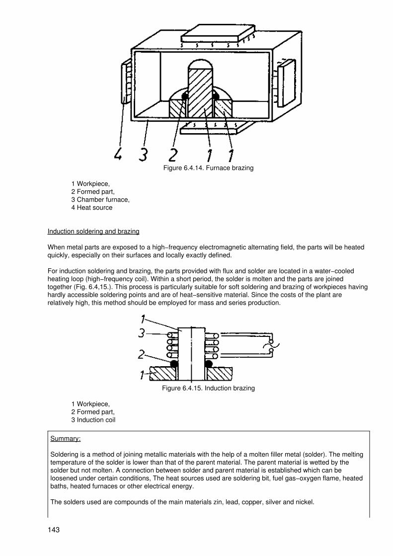
Figure 6.4.14. Furnace brazing
1 Workpiece,2 Formed part,3 Chamber furnace,4 Heat source
Induction soldering and brazing
When metal parts are exposed to a high−frequency electromagnetic alternating field, the parts will be heatedquickly, especially on their surfaces and locally exactly defined.
For induction soldering and brazing, the parts provided with flux and solder are located in a water−cooledheating loop (high−frequency coil). Within a short period, the solder is molten and the parts are joinedtogether (Fig. 6.4,15.). This process is particularly suitable for soft soldering and brazing of workpieces havinghardly accessible soldering points and are of heat−sensitive material. Since the costs of the plant arerelatively high, this method should be employed for mass and series production.
Figure 6.4.15. Induction brazing
1 Workpiece,2 Formed part,3 Induction coil
Summary:
Soldering is a method of joining metallic materials with the help of a molten filler metal (solder). The meltingtemperature of the solder is lower than that of the parent material. The parent material is wetted by thesolder but not molten. A connection between solder and parent material is established which can beloosened under certain conditions, The heat sources used are soldering bit, fuel gas−oxygen flame, heatedbaths, heated furnaces or other electrical energy.
The solders used are compounds of the main materials zin, lead, copper, silver and nickel.
143

Fluxes for the removal of the oxide layer on the workpiece and for improving the capability of being wettedare used in the form of liquid, paste powder or in connection with the solder and consist of zinc chloridesolutions, colophonium or boron compounds.
6.4.3. Glueing
By means of glueing, workpieces of any material can be joined together, that is to say, metals can be joinedwith metals or metals with non−metals. For this purpose, an adhesive is used which hardenes and joins theparts (Fig. 6.4.16.).
Figure 6.4.16. Glueing with the help of a grooved ledge
1 Workpiece,2 Grooved ledge,3 Glued joint
Since heating is not necessary in general, heat−sensitive parts are glued. Glueing is favrourable with respectto costs.
Means of work
The adhesive is decisive for the strength of the glued joint.
According to fields of application, a distinction is made between:
− adhesive for bonding metals,− adhesive for bonding wood,− adhesive for bonding plastics,− universal adhesive.
According to the processing temperature, a distinction is made between:
− cold−hardening adhesive,− hot−hardening adhesive.
According to the chemical basis as the main feature of classification, a distinction is made between:
− epoxy resin bonding agent,− polyester resin bonding agent,− phenol resin bonding agent.
Further means of work are mixing vessels, dosing devices and fixing devices.
144

Procedure
The adhesive applied to the surface between the parts to be joined hardens due to chemical reaction andjoins by adhesion power. The adhesive sticks to irregularities of the surface and chemical bonding forcescome into action. A non−detachable joint is produced. For a firm and durable glued joint, strict observation ofthe specified technology is of particular importance.
Preparing the parts to be joined. Determining the type of joint, deburring, straightening, mating the parts.
Preparing the adhering groove. In accordance with the joint, a groove of a surface as large as possible mustbe selected. Cutting the groove and mating the parts.
Pre−treatment of the surface to be glued. Removal of contamination, grease, acids, oxides and rougheningthe surface.
Applying the adhesive. Mixing and applying the adhesive according to specifiactions.
Mating the parts to be joined. Putting the parts together, securing them in their position, clamping the partswith uniform pressure on the entire surface to be glued. Observation of specified temperatures.
Curing the adhesive. Different curing conditions (temperature, pressure, time and protective gas) must beobserved.
The penetration of the adhesive into the pores of the material forms, after curing, a purely mechanicalconnection.
After−treatment of the site glued. Chip−detaching tretament of the area glued (removal of superfluousadhesive) and preservation (lacquering, covering) may be necessary. Similar to welding and soldering, thejoint is decisive for the arrangement (Table 6.7.).
Table 6.7. Joint and groove in glueing
Representation Designation
overlapped joint
one−sided strap joint
two−sided strap joint
groove joint
145

shank joint
Application
The joining of inhomogeneous metals and non−metals without weakening the cross−section is possible. Theglued joint is used
− in automotive engineering for panelling, equipment, enclosures
− ship building
− aircraft manufacture for equipment, bracings,
− machine building for composite construction of bearings, gear mechanisms, tool and platefastenings.
Glueing has gained a wide field of application in wood working and in the plastic industry for a long timealready. Glueing is favourable with respect to costs and easily performed.
Summary:
Metals and non−metals in any combination can be joined together with the help of anadhesive. Bonding agents prepared on different chemical bases are used which cure and joinby adhesive power, A non−detachable joint is produced.
For the joining operation, the strict observance of a specified technology is indispensable.Glued joints are used especially in cases where a weakening of the cross−section as aconsequence of joining is not permitted.
Glueing is also used when low operating temperatures are desired, for dense and smoothjoints or for joining different materials. Since many adhesives are detrimental to health, therelevant labour protection and safety regulations must be observed!
Control questions
6.1. Describe the production of an internal thread!
6.2. What is a direct connection and what is an indirect connection?
6.3. What are the parts of which a screwing or bolting can consist?
6.4. What is the purpose of screw locking devices?
6.5. How are grooves for keys produced?
6.6. What are the possibilities of use of the key?
6.7. Why are round−ended feather keys required especially for axial mobility?
6.8. Explain the most important fields of application of the feather key joint!
6.9. Why is a pinned joint detachable?
6.10. Explain the use of the pin for securing the location and for fastening!
6.11. Explain the mode of action of a grooved pin!
6.12. What are the individual operations to be observed for rivetting?
6.13. Tell examples of rivetted joints from your field of work!
146

6.14. What are the differences between interference fit, expansion fit and shrink fit?
6.15. Describe the procedure of thermit welding!
6.16. When is repouring used?
6.17. What are the tools for the production of joints made by striking?
6.18. Describe a simple fold!
6.19. What are the directions for folding over a flanged border?
6.20. Is it possible to produce leak−proof flanged joints?
6.21. How can a pipe be attached to a disk by crimping?
6.22. What are the purposes of crimping?
6.23. Relate possibilities of using split pins!
6.24. Why is the joint made by lugs particularly suitable for mass production?
6.25. What are the sources of heat to be used for welding?
6.26. What are the differences between fusion welding and pressure welding?
6.27. Explain the terms of joint of the metals to be welded, shape of the groove and weld seam !
6.28. Whan is soldering used?
6.29. What is the permissible height of the melting point of solder?
6.30. What is the function of the flux?
6.31. What are the materials of which the most important solders are made?
6.32. What is the technology to be observed for glueing?
6.33. What are the preparatory operations to be performed before the application of the adhesive?
6.34. How is a glued joint arranged?
7. Manufacturing Method of Coating
Workpieces are subject to wear during their use. The destruction by chemical reaction with the environment,called corrosion, starting from the surface of metallic workpieces, and the wear taking place at the surfaceentail high losses. Added to this is the fact that high expenditures are required for repairs and maintenanceoperations necessary to remove or avoid such damages. Since corrosion and wear mainly occur on thesurface of workpieces, it is particularly economical to carry out protection by coating.
Keep in mind:
Coating is the application of a firmly adhering layer of a shapeless substance to a workpiece. The workpiecemay take part in the formation of the coat by reaction with the coating substance.
Besides the avoiding of losses, coating is used for further essential tasks:
− improving the appearance of the workpieces− achieving new properties of the workpieces− improving the slidability and the absorption of lubricants
147

− reduction of the resistance to forming− restoration of the workpiece to serviceability
The different purposes of coating call for the use of very different coating substances. Coating substance isthe material that forms the layer on the workpiece. This may be associated with a reaction with the material ofthe workpiece. When contacting the workpiece, the coating substance must be shapeless. Shapelesssubstances are powder, liquids, gases or vapours (Table 7.1.).
Table 7.1. Coating substances
The application of the coating substance to the workpiece is largely determined by the state of aggregation ofthe coating substance. It can be solid, liquid, gaseous or ionized.
The classification of the manufacturing main group "coating" is effected according to the four possible statesof the coating substance when contacting the workpiece (Table 7.2.).
Table 7.2. Survey of methods of coating
Coating with:
solidcoating
substance
liquidcoating
substance
gaseouscoating
substance
ionizedcoating
substance
− grinding− fusing on− electrical deposition
− dipping− pouring on− spraying on− brushing on− welding on
− evaporation coating − metal deposition without externalcurrent
− metal deposition with externalcurrent
− oxidizing without external current
− oxidizing wizh external current
Summary:
148
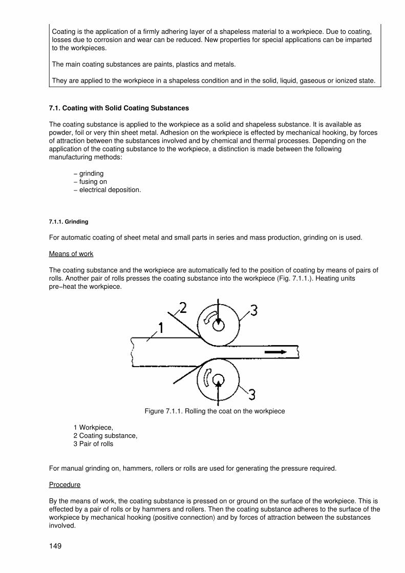
Coating is the application of a firmly adhering layer of a shapeless material to a workpiece. Due to coating,losses due to corrosion and wear can be reduced. New properties for special applications can be impartedto the workpieces.
The main coating substances are paints, plastics and metals.
They are applied to the workpiece in a shapeless condition and in the solid, liquid, gaseous or ionized state.
7.1. Coating with Solid Coating Substances
The coating substance is applied to the workpiece as a solid and shapeless substance. It is available aspowder, foil or very thin sheet metal. Adhesion on the workpiece is effected by mechanical hooking, by forcesof attraction between the substances involved and by chemical and thermal processes. Depending on theapplication of the coating substance to the workpiece, a distinction is made between the followingmanufacturing methods:
− grinding− fusing on− electrical deposition.
7.1.1. Grinding
For automatic coating of sheet metal and small parts in series and mass production, grinding on is used.
Means of work
The coating substance and the workpiece are automatically fed to the position of coating by means of pairs ofrolls. Another pair of rolls presses the coating substance into the workpiece (Fig. 7.1.1.). Heating unitspre−heat the workpiece.
Figure 7.1.1. Rolling the coat on the workpiece
1 Workpiece,2 Coating substance,3 Pair of rolls
For manual grinding on, hammers, rollers or rolls are used for generating the pressure required.
Procedure
By the means of work, the coating substance is pressed on or ground on the surface of the workpiece. This iseffected by a pair of rolls or by hammers and rollers. Then the coating substance adheres to the surface of theworkpiece by mechanical hooking (positive connection) and by forces of attraction between the substancesinvolved.
149

Application
By grinding on, coated plates (clad plates) can be produced for many fields of application. Large numbers ofsmall parts can be coated economically. Paint bases for various paints are produced. Coating can be carriedout automatically.
Summary:
In grinding on, the shapeless solid coating substance is applied to the surface of the workpiece by pressureand grinding. Due to positive connection, it adheres firmly to the workpiece surface; in addition, forces ofattraction act between the substances involved. By automation, high economical results can be achieved bygrinding on.
7.1.2. Fusing on
Low melting coating substances can be applied favourably by fusing on. A condition for the use of this methodis the fact that the workpieces have a considerably higher melting point.
Means of work
Industrial furances and other heating plants are employed for pre−heating the workplaces. In case ofautomatic coating, heating is performed in continuous furnaces. Depending on the method used, thepowdered coating substance is fed by pouring devices or by spraying devices or it is whirled up in chambers.
Procedure
Before contacting the coating substance, the workpiece is heated to such a temperature which is high abovethe melting temperature of the coating substance. When now the solid coating substance in the form ofpowder or flakes contacts the workpiece surface, it will melt on the latter. It spreads and forms, a coat. Thecoating substance may be sprayed on (Fig. 7.1,2.) or sprinkled on.
Figure 7.1.2. Fusing on by spraying the coating substance on
1 Workpiece,2 Coating powder,3 Compressed air,4 Heater
The hot workplace may be rolled in the coating substance (Fig. 7,1.3.) or it may be introduced into a chamberwhere the coating substance is whirled up (Fig. 7.1.4.).
150

Figure 7.1.3. Fusing on by rolling the workpiece in the coating substance
1 Workpiece (heated),2 Coating substance powder,3 Coating substance container
Figure 7.1.4. Fusing on in the swirl chamber
1 Workpiece, (heated)2 Coating substance powder, (swirled on),3 Swirl chamber,4 Coated workpiece,5 Compressed air.
Application
Fusing on is particularly suitable for the coating with thermoplastics. They have a low melting point and call forlimited pre−heating of the workpieces, This method of coating ensures a good resistance to corrosion ofmetallic workpieces. Low−melting metals such as lead and tin can also be applied to workpieces of steel,glass and ceramic material by fusing on. When using swirl chambers, automation of the process is possible.
Summary:
For fusing on, the workpieces to be coated are pre−heated to a temperature which is above the meltingtemperature of the coating substance. When the solid coating substance contacts the hot workpiece, itmelts on the latter and spreads into a firmly adhering layer. When the workpiece is cooling down, the coat issolidifying. The low−melting coating substances include thermoplastics and low−melting metals.
7.1.3. Electrical Deposition
For protection against corrosion, frequently paints with a high content of hard substances such as metaloxides and metal carbides and rubber grains are used. For this purpose, the method of electrical deposition isemployed.
151

Means of work
Containers are used for the working liquid. The coating is effected by dipping. For the directed motion of thecoating substance towards the workpiece, an electric direct current is required. Workpiece and container arecharged in this manner.
Procedure
The neutral coating substance in the form of powder is added to the container with the working liquid. In thisway, the coating substance is charged electrically. When now the workpiece is added and charged opposite tothe charge of the coating substance, the workpiece will attract the coating substance. The solid particles of thecoating substance move in the working liquid towards the workpiece. They are deposited on the latter, forminga layer having sufficient adhesive power (Fig. 7.1.5.).
Figure 7.1.5. Electrical deposition
1 Workpiece,2 Coating substance,3 Coating substance container,4 Current source for direct current,5 Working liquid
Application
By electrical deposition, thick paints having a high content of hard particles can be applied to metallicworkpieces. Coarse grained coating substances such as rubber grains, metal oxide powder and plastic flakescan be used.
Summary:
In electrical deposition, non−conducting powdered coating substance, usually coarse−grained paints, canbe applied to workpieces in the form of a layer. The particles in the coating substance are electricallycharged by the working liquid and then attracted by the workpiece having a charge of the opposite sign.This method is used in large series and mass production.
7.2. Coating with Liquid Coating Substance
The coating substance is liquid when it contacts the workpiece.
The coating substance is applied to the surface of the workpiece. It must wet the surface when the coat is toadhere well. Therefore, the workpiece must be cleaned before coating. This cleaning procedure can be
152

effected
mechanically: by scratching, brushing and sandblasting,
chemically: by flushing and pickling baths,
thermally: by burning.
Depending on the coating substance used, a properly adhering coat os obtained by cooling down, drying,curing and crystallization.
Adhesion is due to
− positive connection between the cold coating substance and the workpiece surface,− attractive forces between the substances involved,− union of the metallic substances involved (forming of alloys).
Depending on the method of application of the liquid coating substance to the workpiece, a distinction is madebetween the following processes:
− dipping− pouring on− spraying on− brushing on− welding on (building−up welding)
7.2.1. Dipping
Workpieces made in series and mass production are very economically coated by dipping; material is savedin this process.
Means of work
The normally liquid coating substance is available in dipping tanks adapted to the workpiece size. Moltencoating substance calls for a continuous supply of heat to the dipping baths. The workpieces are fed to the dipmanually or automatically by means of conveying devices. Quick setting of the coat can be achieved by dryingequipment.
When working with molten coating substances, protective clothes must be worn because ofthe danger of burns by splashes!
Procedure
The properly prepared and cleaned workpieces are dipped into the coating substance by hand (individualproduction, small series production), mechanically or automatically (for large series and mass production).The workpieces are left unmoved or moved in it for some time while they are wetted by the substance. Afterhaving slowly and uniformly removed the workpieces form the bath, the coating substance solidifies forming afirm layer (Figs. 7.2.1. and 7.2.2.).
153

Figure 7.2.1. Dipping of sheet metal
1 Workpiece,2 Coating substance,3 Dipping container with heating system,4 Conveyor
Figure 7.2.2. Automatic dip coating of workpiece
1 Workpiece,2 Coating substance,3 Dip container4 Conveyor
Application
Dipping is a very economical method for coating small parts, semifinished products (plates, sections) and alsolarge workpieces (such as motorcar bodies). It saves material and is particularly suitable for applying paintsand low−melting metals such as zinc, lead and tin to workpieces. Simple shapes of workpieces are favourablefor the adhesion of the coat.
Summary:
Dipping is a method for immersing the workpiece in the normally liquid or molten coating substance, Coatingin this way is a highly economical process. Dipping is particularly suitable for series and mass productionwhere parts of simple shape and such of any size are coated automatically.
7.2.2. Pouring on
When the coating substance is applied to the workpiece by virtue of its fluidity and gravitational force, then thisprocedure is called pouring on.
Means of work
The coating substance is available in containers which are provided with a pouring device. Molten coatingsubstance must be kept in this state by continuous supply of heat (heating equipment). Nozzles, strippers andsimilar devices ensure the correct arrangement and thickness of the coating substance.
154
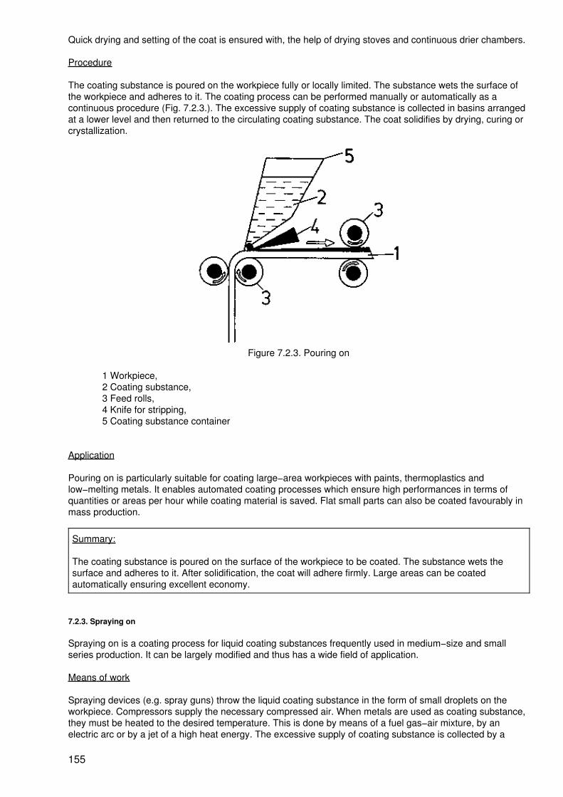
Quick drying and setting of the coat is ensured with, the help of drying stoves and continuous drier chambers.
Procedure
The coating substance is poured on the workpiece fully or locally limited. The substance wets the surface ofthe workpiece and adheres to it. The coating process can be performed manually or automatically as acontinuous procedure (Fig. 7.2.3.). The excessive supply of coating substance is collected in basins arrangedat a lower level and then returned to the circulating coating substance. The coat solidifies by drying, curing orcrystallization.
Figure 7.2.3. Pouring on
1 Workpiece,2 Coating substance,3 Feed rolls,4 Knife for stripping,5 Coating substance container
Application
Pouring on is particularly suitable for coating large−area workpieces with paints, thermoplastics andlow−melting metals. It enables automated coating processes which ensure high performances in terms ofquantities or areas per hour while coating material is saved. Flat small parts can also be coated favourably inmass production.
Summary:
The coating substance is poured on the surface of the workpiece to be coated. The substance wets thesurface and adheres to it. After solidification, the coat will adhere firmly. Large areas can be coatedautomatically ensuring excellent economy.
7.2.3. Spraying on
Spraying on is a coating process for liquid coating substances frequently used in medium−size and smallseries production. It can be largely modified and thus has a wide field of application.
Means of work
Spraying devices (e.g. spray guns) throw the liquid coating substance in the form of small droplets on theworkpiece. Compressors supply the necessary compressed air. When metals are used as coating substance,they must be heated to the desired temperature. This is done by means of a fuel gas−air mixture, by anelectric arc or by a jet of a high heat energy. The excessive supply of coating substance is collected by a
155

suction device. Drying equipment such as continuous furnaces provide quickly a solid layer.
When spraying, usually spray mists of the coating substances are formed which aredetrimental to health.
Further, there is fire and explosion hazard! Good aeration and ventilation are necessary!Wear protective clothing!
Procedure
The normally liquid paint is sprayed on the workpiece by means of compressed air through a nozzle in theform of droplets (Fig. 7.2.4.).
Figure 7.2.4. Spraying on pat
1 Coating substance,2 Compressed air
There, it spreads into a continuous coat forming a layer after drying or curing. Metallic coating substances andthermoplastics are usually fed to the spraying equipment in a solid form (wire) (Figs. 7.2.5. and 7.2.6.) andmolten by heating before spraying (flame−spraying, melt spraying). Good adherence to the surface of theworkpieces calls for careful pre−treatment.
Figure 7.2.5. Melt spraying with fuel gas−oxygen mixture
1 Workpiece,2 Coating substance,3 Fuel gas,
156

4 Oxygen,5 Torch
Figure 7.2.6. Melt spraying with electric arc
1 Workpiece,2 Coating substance,3 Compressed air
Sequence of operations for spraying on
1. Cleaning the surface of the workpiece2. Pre−treatment of the surface (drying)3. Coating4. Aftertreatment of the coat
The quality of the coat and the economy of the process can be improved when by opposite electrical chargeson workpieces and coating substance forces of attraction become effective between them.
Application
Spraying is the most important method for applying normally liquid coating substances, especially the quicklydrying paints. It is a very economical, almost universally applicable method, especially in the case of largeareas to be coated. As a manual method based on hand spray guns, it is very practical and flexibel. Stationaryplants usually operate continuously. They are highly mechanized or automated. This method is particularlysuitable for series production. By melt spraying of metals, workpieces can be restored to serviceability.
Summary:
In spraying, normal−liquid or molten coating substance, heated before spraying, is thrown in the form ofsmallest droplets by compressed air on the workpiece. It spreads on the surface, forming a solid layer afterdrying, curing or crystallization. Spraying is a universally applicable method. It can be used in varnishingshops by means of portable or mobile spraying equipment. When automated, the method is highlyproductive.
7.2.4. Brushing on
For coating individual workpieces with paints, especially during repairs and maintenance operations and forparts of intricate shape, brushing on is used.
Means of work
157

The tools required are brushes of different designs and rollers. Rollers are employed in stationary brushingshops.
Procedure
The normal−liquid paint is taken from the reservoir by dipping the brush or roller into it. The paint adheres tothe brush and the like and can be applied to the workpiece and distributed on it. When using rollers, a highereconomy and a reduced load on the worker can be achieved (Fig. 7.2.7.).
Figure 7.2.7. Automatic brushing on
1 Workpiece,2 Coating substance,3 Feed roll,4 Brushing roll
Application
Brushing is a method of applying normal−liquid coating substance to workpieces. In contrast to other methodsof coating, it is less economical and should only be used when type and shape of the workpiece exclude theuse of other methods. Fields of application are prime coats, repairs and the varnishing shop for paintingindividual parts.
Summary:
Normal−liquid paints are applied to the workpiece by means of brushes or rollers. After drying and curing,the coating substance forms a firmly adhering layer. Economy of this method is limited. It is used for repairsand workpieces of intricate shapes. Automation is possible.
7.2.5. Welding on
Welding is an important method of joining metallic workpieces. It can also be used for coating.
Means of work
Welding torches as used in gas fusion welding or arc welding equipment liquify the metallic coatingsubstance. Its continuous feed in the form of wire to the welding point is effected by feeding devices.
Procedure
The surface of the metallic workpiece is molten together with the metallic coating substance. Coatingsubstance and material of the workpiece must be homogeneous. They must have the same melting point. In
158

the melt, the substances combine and then crystallize.
A continuous coat is produced on a surface seam by seam (Fig. 7.2.8.).
Figure 7.2.8. Welding on
1 Workpiece,2 Electrode with coating substance,3, 4 Welding current supply,5 Arc (welding point)
Welding equipment of every description must be handled with great care because of possibleinjuries to health and fire hazard! Special knowledge and skills are required! The relevantsafety regulations must be observed strictly!
Application
Welding on is a method that may restore worn components to serviceability. Thus, bearing seats, guides,journals, rails, gears and tools can be used again. To parts subject to high mechanical or thermal stresses(valves, guideways), first rate materials can be applied.
Summary:
In welding on (building−up welding), molten metallic coating substance is applied in the form of a layer(seam by seam) to metallic workpieces. The substance unites on the surface of the workpiece, crystallizesand forms a very firmly adhering layer. By means of this method, worn workpieces are restored to properserviceability.
7.3. Coating with Vapour−like or Gaseous Coating Substance
When touching the workpiece, the coating substance is available in a gaseous state or in the form of vapour,This state is achieved by heating the coating substance to very high temperatures. It changes from the solidvia the liquid to the gaseous state. Then the coating substance particles are very rich in energy. They strikethe workpiece and, emitting their energy, become attached to its surface. They condense or crystallize on thesurface forming a very thin but firm coat. According to the way of winning the coating substance, a distinctionis made between evaporation coating and evaporation coating after thermal separation.
7.3.1. Evaporation Coating
Means of work
In evaporation chambers, the coating substance is transformed into the gaseous phase. Heating to a hightemperature is effected by electrical heating (Fig. 7.3.1.) or by radiation of high energy (Fig. 7.3.2.).
159

Figure 7.3.1. Evaporation coating with electric resistance heating
1 Workpiece,2 Coating substance,3 Evaporation container,4 Heating
Figure 7.3.2. Evaporation coating by radiation of high energy
1 Workpiece,2 Coating substance,3 Radiation of high energy,4 Evaporation container (cooled),5 Point of evaporation
In the chambers, there is a vacuum or a verly low pressure.
Procedure
The pure, usually metallic coating substance is evaporated under vacuum while heat is added. The vapourparticles spread out and touch the cold workpiece. They give off their thermal energy and become attached tothe surface. They condense or crystallize and form a firmly adhering coat. The adhesion of the coat can beimproved by a careful preparation of the workpiece surface. The vacuum favours the evaporation and thespreading out of the vapour particles and prevents chemical influences on the coating substance.
Application
160

By evaporation coating, particularly thin metallic layers can be formed on the workpiece surface. Essentialcoating substances for obtaining special properties are: silver, aluminium, cobalt, gold, copper, chromium,nickel, platinum and titanium. Special properties are: high conductivity for electrical current, very goodreflectance, high corrosion resistance, and high resistance to wear, Evaporation coating is used in electricalengineering to a great extent.
Summary:
In evaporation coating, the pure coating substance is heated to a high temperature. It evaporates in avacuum. The vapour particles spread out, touch the workpiece and become attached to the surface of thelatter in the form of a thin layer. Particularly valuable metals are used as coating substances which impartnew properties to the workpieces.
7.4. Coating with an Ionized Coating Substance
For coating with solid, liquid or gaseous coating substance, it is available as a normal pure substance. Itconsists of smallest particles which are called atoms. These atoms are not electrically charged, they areelectrically neutral. The coating substance is applied to the workpiece in different ways and produces a moreor less properties adhering layer. En this connection, reactions between the coating substance and theworkpiece may occur. They improve the adherence of the coat.
When coating in the ionized condition, the coating substance is not given in the form of a pure atomicsubstance. It does not consist of smallest electrically neutral particles, The coating substance has beenchemically dissolved. For example, it is in a liquid as a dissolved metal salt. Since now the smallest particlesare ions which, in contrast to the atoms, have a certain electrical charge, the coating substance is calledionized.
The electrical charge of the particles (ions) makes it possible to enforce a certain direction of their motion. Thebasis of this fact is the law according to which different electrical charges attract each other. Due to a chargingof the workpieces (there are positive and negatige charges) by means of a voltage source (direct currentcircuit of the battery), it can be achieved that the ions of the solution move towards the immersed workpiece.They are attracted by the latter and form a coat on it. For this purpose the workpiece must always beelectrically conductive. This condition is complied with by the metallic workpieces.
Metals always try to unite. They can be dissolved in liquids, for example. This is effected at differentintensities, depending on the fact whether or not it is a noble metal.
In the liquid, the metal emits smallest particles − the ions − with a positive charge. Consequently, the residualworkpiece is charged electrically negative. This automatically proceeding process is utilized in coating.
The electrically charged particles (ions) of the coating substance become attached to the workpiece. There,they are discharged and then again are electrically neutral small particles, namely, atoms. Frequently,reactions with the material of the workpiece take place. This means that the latter may take part in theformation of the coat directly as a substance.
When handling ionized liquids (acids, lyes, solutions), carefully observe the relevant safetyregulations!
Wear protective clothing because ionized liquids are detrimental to health!
The use of electrical current in a few processes calls for the strict observance of the relevantregulations regarding the use of electrical current !
Depending on the coating method, coating from the ionized state is grouped in:
− metal deposition without external current− metal deposition with external current− oxidizing without external current− oxidizing with external current
161

7.4.1. Metal Deposition without External Current
Means of work
Tanks contain the aqueous solution with the coating substances. Cleaning baths serve for the pre−treatmentof the workpieces, flushing and neutralizing baths serve for the aftertreatment of the coat. Heating unitsmaintain the correct temperature of the baths.
Procedure
The workpieces to be coated are placed into the bath. The surfaces are slightly dissolved − they emit somepositive metal ions. Consequently, the workpiece is charged negatively, attracting the positive ions containedin the coating substance in the solution. The ions of the coating substance move towards the workpiece. Theybecome attached to it, again are turned into atoms and form a coat of nobler metal on the workpiece (Fig.7.4.1.).
Figure 7.4.1. Metal deposition without external current
1 Workpiece, (ignoble, negatively charged)2 Solution with ionized coating substance,3 Container
Application
By metal deposition without external current, copper and nickel coats on steel are favourable produced.Nickel−cobalt coats and thinnest gold and silver coats are used especially in electrical engineering.
Summary:
For metal deposition without external current, the metallic workpiece is immersed in a solution of the coatingsubstance. Electrical forces of attraction are brought about. The coating substance is attracted by theworkpiece. It becomes attached to the surface of the latter and forms a very thin layer. Only nobler metalcoats can be deposited on the metallic workpiece. This process can be automated for use in seriesproduction.
7.4.2. Metal Deposition with External Current
Means of work
The solution of the coating substance is contained in tanks.
The necessary working current must be supplied from a direct current source. The workpieces are carried bysuspension devices and conveyors. Pre−treatment and aftertreatment are effected in flushing and cleaningbaths. Heating devices maintain the correct temperatures of the bath,
Procedure
The metallic workpieces to be coated are connected to the negative pole of the voltage source. Consequently,they are negatively charged. When they are immersed in the tank, they attract the positive ions of the metallic
162
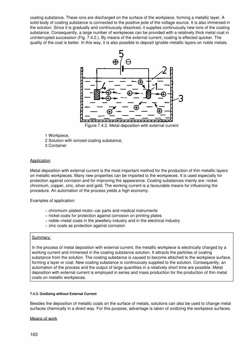
coating substance. These ions are discharged on the surface of the workpiece, forming a metallic layer. Asolid body of coating substance is connected to the positive pole of the voltage source. It is also immersed inthe solution. Since it is gradually and continuously dissolved, it supplies continuously new ions of the coatingsubstance. Consequently, a large number of workpieces can be provided with a relatively thick metal coat inuninterrupted succession (Fig. 7.4.2.). By means of the external current, coating is effected quicker. Thequality of the coat is better. In this way, it is also possible to deposit ignoble metallic layers on noble metals.
Figure 7.4.2. Metal deposition with external current
1 Workpiece,2 Solution with ionized coating substance,3 Container
Application
Metal deposition with external current is the most important method for the production of thin metallic layerson metallic workpieces. Many new properties can be imparted to the workpieces. It is used especially forprotection against corrosion and for improving the appearance. Coating substances mainly are: nickel,chromium, copper, zinc, silver and gold. The working current is a favourable means for influencing theprocedure. An automation of the process yields a high economy.
Examples of application:
− chromium−plated motor−car parts and medical instruments− nickel coats for protection against corrosion on printing plates− noble−metal coats in the jewellery industry and in the electrical industry− zinc coats as protection against corrosion
Summary:
In the process of metal deposition with external current, the metallic workpiece is electrically charged by aworking current and immersed in the coating substance solution. It attracts the particles of coatingsubstance from the solution. The coating substance is caused to become attached to the workpiece surface,forming a layer or coat. New coating substance is continuously supplied to the solution. Consequently, anautomation of the process and the output of large quantities in a relatively short time are possible. Metaldeposition with external current is employed in series and mass production for the production of thin metalcoats on metallic workpieces.
7.4.3. Oxidizing without External Current
Besides the deposition of metallic coats on the surface of metals, solutions can also be used to change metalsurfaces chemically in a direct way. For this purpose, advantage is taken of oxidizing the workpiece surfaces.
Means of work
163

The ionized active solution is contained in tanks. The workpieces are immersed in this solution by means ofsuspension devices. Pretreatment and aftertreatment baths and drying facilities are required. By heatingplants the correct temperature of the baths is reached.
Procedure
The metallic workpieces, primarily steel parts, are immersed in the active solution. This active solution (saltsolution, acid) releases oxygen when a metallic workpiece is being immersed. The oxygen immediately reactswith the workpiece surface, transforming it into a metal oxide layer (Fig. 7.4.3.).
Figure 7.4.3. Oxidizing without external current
1 Workpiece,2 Oxygen from the active solution,3 Container,4 Active solution
Application
By oxide coats a short−time protection against corrosion especially on steel parts is achieved. When addingpigments, one obtains a decorative black metallic bright coat on the workpieces. Oxidizing without externalcurrent is used especially for small and mass−produced parts such as screws, bolts and nuts and fittings.Automation of this process is possible.
Summary:
In the process of oxidizing without external current, metallic workpieces are oxidized on their surfaces by anactive substance which releases oxygen. A very thin coat is produced which serves for a short−timeprotection against corrosion. By an addition of pigments, a black colouration on steel can be obtained.
7.4.4. Oxidizing with External Current
Means of work
The means of work are the same as are used for oxidizing without external current. A voltage source isadded, however, which supplies the necessary working current (direct current or alternating current).
Procedure
The metallic workpiece is immersed into the active solution (salt solution, acid). Consequently, oxygen isreleased which oxidizes the surface of the workpiece.
164

Figure 7.4.4. Oxidizing with external current
1 Workpiece,2 Released oxygen,3 Container4 Active solution,5 Current source
By the electric current which passes through the solution and the workpiece, the formation of oxygen andcontinued oxidation is continuously excited (Fig. 7.4.4.).
In this way, thicker coats than are produced in oxidizing without external current can be achieved. By theapplication of dyestuffs, different colours of the oxide layer can be produced. Fig. 7.4.5. shows the differencebetween metal deposition and oxidizing on the basis of the formed protective layer.
Figure 7.4.5. Forming the coat of protection in metal deposition and in oxidizing
a Metal deposition
1 Metal coat,2 Workpiece,
b Oxidizing
2 Workpiece,3 Oxide coat
Application
Oxidizing with external current is used for the production of thicker oxide layers on workpieces of aluminiumand its alloys. Consequently, it ensures a better resistance to corrosion of these workpieces. By an addition ofdyestuffs, different colours can be obtained. This process is used in the processing of aluminium alloys inseries and mass production. Automation is possible.
Summary:
165

In oxidizing with external current, the surface of the workpiece is oxidized after immersion into the activesolution (acid). The current passing through the active solution and the workpiece, continuously producesnew oxygen. As a consequence, thicker coats of oxide can be produced as a protective against corrosion.By an addition of dyestuffs, the workpieces can be provided with various colours.
Control questions
7.1. What are the targets that can be attained by coating?
7.2. Relate new properties which are imparted to workpieces by coating!
7.3. What are the advantages of clad plates and where are such plates used?
7.4. What are the possibilities of producing the pressure necessary for grinding on?
7.5. What are the conditions to be complied with by the material of the workpiece and by the coatingsubstance for melting on?
7.6. Why must the surface of the workpieces to be coated be pretreated?
7.7. What are the methods for liquefying metallic coating substances?
7.8. How can metallic coating substances be evaporated?
7.9. What are the metallic coating substances that can be deposited on metallic workpieces by the method ofmetal deposition without external current?
7.10. Why can thicker oxide coats be achieved by oxidizing with external current than by oxidizing withoutexternal current?
8. Manufacturing Methods Changing the Properties of Materials
The manufacturing methods for working metallic materials pursue one of two possible different aims.
Firstly, they shall produce or modify a certain shape of the workpiece. These methods include, e.g. casting,turning in a lathe, welding and bending. Secondly, they shall change the properties of workpieces withoutinfluencing their shape. For this purpose, the manufacturing methods for changing the properties of materialsare used.
Keep in mind:
Changing the properties of materials is the changing of the material properties inherent in a solid workpiecewithout influencing its shape (slight changes in the shape are unintentional; they do not belong to theessence of these methods).
The manufacturing methods changing the properties of materials are used in order to
− adapt the properties of the workpiece maximally to the purpose,− enable further machining of the workpiece at all, or− ensure the serviceability and service life as well as the stressability of the workpiece.
By the manufacturing methods changing the properties of materials, the following essential properties can beinfluenced: hardness, wearing behaviour, strength, corrosion resistance, magnetic properties, formingbehaviour, electrical properties, elasticity, capability of being cut, toughness and others.
The properties of materials, which are in a solid state and possess a firm shape, can be changed in differentways. For example, by forming at normal temperature (cold deformation), a remarkable hardening of thematerial, an increase of its brittleness and of the resistance to further deformation can be achieved.
166

Of the various possibilities of changing the properties of materials, the heat treatment of metallic materials,especially the heat treatment of steel, is of paramount importance.
Keep in mind:
Heat treatment is defined as the heating of a workpiece to a certain temperature (depending on the target),the maintaining of this temperature and a subsequent reduction of the temperature to normal temperature.
The temperature and the duration of the three steps are determined by the change in the properties of thematerial to be attained. Depending on the selection of the heating conditions, the temperature to bemaintained and the duration of this maintenance as well as the cooling conditions, different processes takeplace inside the workpiece which then cause the manifestation of various properties. These processes changethe internal structure of the metallic workpieces without influencing their external shapes. A rearrangementand an elimination of smallest particles of matter, which take part in the construction, occur or smallestparticles of matter (atoms) are additionally incorporated into the solid metallic body, a fact which is also calledinclusion.
The method of changing the properties of material by heat treatment is used for steels and for non−ferrousmetal alloys (aluminium and copper alloys). The main importance is the changing of the properties ofunalloyed steels. In this connection, the most importance manufacturing methods are
− annealing− hardening− tempering and tempering after hardening.
Summary:
When changing the properties of materials, the properties of solid workpieces are changed. The shape ofthe workpieces is retained. Changing the properties of materials is mainly effected by a heat treatment towhich the metallic workpieces are subjected. The workpieces are heated to a certain temperature,maintained at this temperature for a certain period and then cooled down to normal temperature. Thechange in the properties then is the result of a rearrangement, elimination or inclusion of smallest particlesof matter inside the workpiece.
8.1. Changing the Properties of Materials by a Rearrangement of Particles of Matter
8.1.1. Annealing
Annealing is defined as a group of methods which achieve different changes in properties of materials butproceed according to the same principle of action. Annealing processes are widely used in the processing ofmetallic materials.
Means of work
Different furnaces are used for heating: chamber furnaces, continuous furnaces, muffle furnaces andmultiple−hearth roasters. They are provided with electrical or gas heating systems. Individual small parts orparts of workpieces can also be heated in forge fires or in an open flame. In series or mass production, theworkpieces are moved into or through the furnaces by means of conveyors. In this connection, automation ofthe annealing process is possible.
Procedure
The workpiece is heated to annealing temperature. This temperature is maintained for some time until thewhole workpiece is properly heated through. Subsequently, the workpiece is cooled down slowly and at auniform rate. Long periods of annealing and high annealing temperatures frequently cause detrimental sideeffects, are uneconomical and should be avoided.
Due to the high working temperatures, health can be impaired!
167
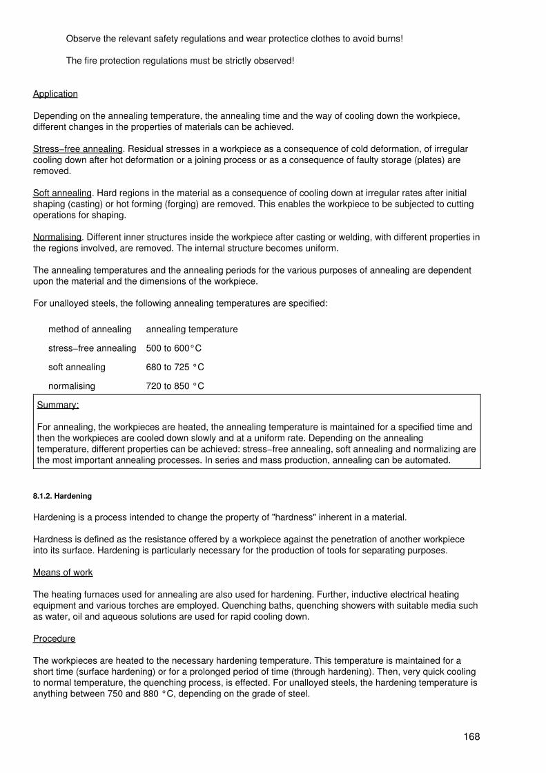
Observe the relevant safety regulations and wear protectice clothes to avoid burns!
The fire protection regulations must be strictly observed!
Application
Depending on the annealing temperature, the annealing time and the way of cooling down the workpiece,different changes in the properties of materials can be achieved.
Stress−free annealing. Residual stresses in a workpiece as a consequence of cold deformation, of irregularcooling down after hot deformation or a joining process or as a consequence of faulty storage (plates) areremoved.
Soft annealing. Hard regions in the material as a consequence of cooling down at irregular rates after initialshaping (casting) or hot forming (forging) are removed. This enables the workpiece to be subjected to cuttingoperations for shaping.
Normalising. Different inner structures inside the workpiece after casting or welding, with different properties inthe regions involved, are removed. The internal structure becomes uniform.
The annealing temperatures and the annealing periods for the various purposes of annealing are dependentupon the material and the dimensions of the workpiece.
For unalloyed steels, the following annealing temperatures are specified:
method of annealing annealing temperature
stress−free annealing 500 to 600°C
soft annealing 680 to 725 °C
normalising 720 to 850 °C
Summary:
For annealing, the workpieces are heated, the annealing temperature is maintained for a specified time andthen the workpieces are cooled down slowly and at a uniform rate. Depending on the annealingtemperature, different properties can be achieved: stress−free annealing, soft annealing and normalizing arethe most important annealing processes. In series and mass production, annealing can be automated.
8.1.2. Hardening
Hardening is a process intended to change the property of "hardness" inherent in a material.
Hardness is defined as the resistance offered by a workpiece against the penetration of another workpieceinto its surface. Hardening is particularly necessary for the production of tools for separating purposes.
Means of work
The heating furnaces used for annealing are also used for hardening. Further, inductive electrical heatingequipment and various torches are employed. Quenching baths, quenching showers with suitable media suchas water, oil and aqueous solutions are used for rapid cooling down.
Procedure
The workpieces are heated to the necessary hardening temperature. This temperature is maintained for ashort time (surface hardening) or for a prolonged period of time (through hardening). Then, very quick coolingto normal temperature, the quenching process, is effected. For unalloyed steels, the hardening temperature isanything between 750 and 880 °C, depending on the grade of steel.
168

A successful change in the property of "hardness" in steel depends on:
− the hardenability of the steel (grade of steel, constituents)− the realization of the correct hardening temperature− the very rapid cooling (quenching).
Only when all of the three preconditions are complied with, the hardness will be increased.
Surface hardening. Since a specified hardness usually is only required at the surface of the workpiece, a thinsurface layer only will be heated. This layer is then quenched. The workpieces hardened in this way excel in ahard, wear−resistant surface but have a soft, tough and very firm core.
Heating is performed by means of torches (open flame) (Fig. 8.1.1.)
Figure 8.1.1. Surface hardening in the form of feed hardening with torch and shower−bath or by means ofelectrical current (inductive heating (Fig. 8.1.2.).
1 Workpiece,2 Torch,3 Quenching, shower−bath,4 Heated layer,5 Hardened layer
Quenching is effected immediately after heating by means of quenching showers.
169
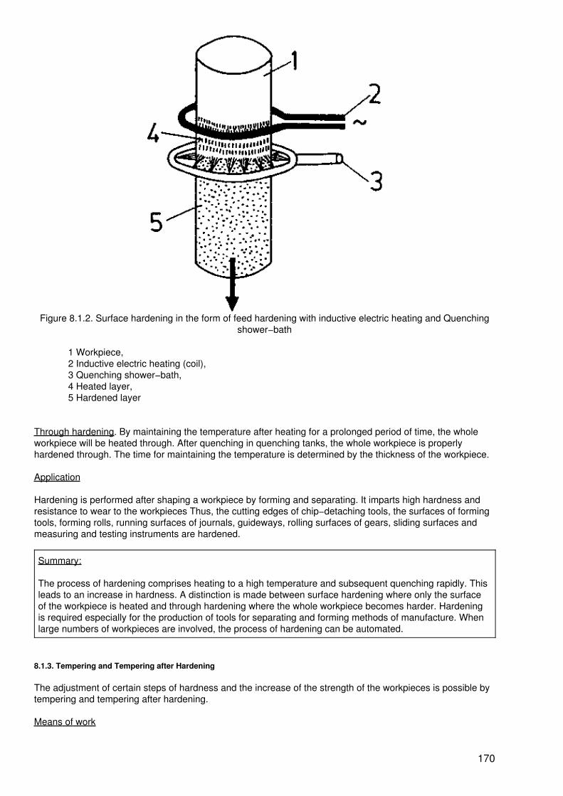
Figure 8.1.2. Surface hardening in the form of feed hardening with inductive electric heating and Quenchingshower−bath
1 Workpiece,2 Inductive electric heating (coil),3 Quenching shower−bath,4 Heated layer,5 Hardened layer
Through hardening. By maintaining the temperature after heating for a prolonged period of time, the wholeworkpiece will be heated through. After quenching in quenching tanks, the whole workpiece is properlyhardened through. The time for maintaining the temperature is determined by the thickness of the workpiece.
Application
Hardening is performed after shaping a workpiece by forming and separating. It imparts high hardness andresistance to wear to the workpieces Thus, the cutting edges of chip−detaching tools, the surfaces of formingtools, forming rolls, running surfaces of journals, guideways, rolling surfaces of gears, sliding surfaces andmeasuring and testing instruments are hardened.
Summary:
The process of hardening comprises heating to a high temperature and subsequent quenching rapidly. Thisleads to an increase in hardness. A distinction is made between surface hardening where only the surfaceof the workpiece is heated and through hardening where the whole workpiece becomes harder. Hardeningis required especially for the production of tools for separating and forming methods of manufacture. Whenlarge numbers of workpieces are involved, the process of hardening can be automated.
8.1.3. Tempering and Tempering after Hardening
The adjustment of certain steps of hardness and the increase of the strength of the workpieces is possible bytempering and tempering after hardening.
Means of work
170

The heating and quenching equipment used for hardening is also employed for tempering and tempering afterhardening.
Procedure
At first, the workpieces are treated in the same way as for hardening: heating to hardening temperature −maintaining of this temperature for a shorter or longer period − rapid quenching.
In this way, a high hardness is achieved. This high hardness is associated with an intense brittleness of theworkpiece. The workpiece is "dead hard". By heating the workpiece once more after quenching, this hardnesscan be partly or fully removed.
Tempering. The "dead hardness" after hardening is partly removed by subsequent heating. The higher thetemperature of re−heating, the more hardness will be lost. The required working hardness can be adjusted.Subsequently, the workpiece is rapidly cooled to normal temperature. When tempering from the outside,re−heating after quenching is carried out by means of a heating equipment. The required temperingtemperature can be exactly adjusted in this way. Tempering from the outside is used especially in series andmass production.
When the working hardness is required only in certain points of the workpiece, the workpiece is quenched insuch a way that residual heat is retained at other points. After quenching, this heat returns from inside to thepoint to be hardened. When in this place the tempering temperature is reached, the workpiece is rapidlycooled to normal temperature.
The temperature of tempering can be distinguished by the colour of the workpiece surface (temper colours).This method of tempering is used especially for manually hardening individual parts.
Table 8.1. Tempering temperatures of tools
Tool Tempering temperature Temper colour
Hatchet, axe 300 °C dark blue
Drill 220 °C light yellow
File 320 °C grey−blue
Hammer 260 °C dark red
Punch 250 °C light brown
Chisel 270 °C light red
Saw 310 °C light blue
Tempering after hardening. If the process of heating after quenching is carried out with higher temperatures,then the hardness is removed almost completely. Instead, the strength and toughness of the material isdistinctly increased.
Application
Tempering. The hardness present in the workpiece after hardening is reduced. The working hardnessrequired for the field of application can be adjusted. This method is utilized especially for the tools ofseparating and forming methods.
Tempering after hardening. The strength of the workpiece can be increased. This is used especially forworkpieces subject to heavy duties.
Summary:
In tempering, the hardness required for the workpiece is produced. The excessive hardeness is removed,the working hardness desired is adjusted. For this purpose, the workpiece is slightly heated after quenching.After reaching the tempering temperature, the workpiece is rapidly cooled to normal temperature. In
171

tempering after hardening, the hardness is completely removed by reheating to a higher temperature (500to 650 °C) after quenching. As a consequence, the strength and toughness of the material are increased.
Control questions
8.1. Relate properties which are changed by the manufacturing methods changing the properties of materials!
8.2. What are the changes in properties which can be effected by annealing processes?
8.3. What is the difference between surface hardening and through hardening?
8.4. How can the strength of an unalloyed steel be increased?
8.5. What is meant by tempering from inside?
9. Trends of Manufacturing Methods
In the preceding Sections, it has become obvious that it is the aim of all methods to produce geometricallydetermined solid bodies, individually or combined, in the form of useful products.
Starting from the inital form (blank), preceding to the intermediate form (semi−finished product), the finalshape (finished product) has been achieved.
It is not insignificant if one, two or several intermediate forms are necessary.
In case of several intermediate forms, more tools and machines are required. This means increasedconsumption of material and energy. This also increases the expenditure of manufacture, operation and repairand maintenance of tools and machines.
Therefore, one endeavours to use only a few or, what is still better, no intermediate forms at all.
The use of methods is largely influenced by the degree of automation of the manufacturing equipment.
Besides the higher automation of the processing unit (NC machine tool, CNC machine tool), the still prevailingmanual handling of tools and workpieces is replaced by industrial robots leading to independently workingmanufacturing cells in an enterprise where machine attendance is scarcely required.
Below we try to show the main trends for each of the six main manufacturing groups (initial shaping, forming,separating, joining, coating and changing the properties of materials).
9.1. Initial Shaping
This main manufacturing group is characterized by the fact that intermediate forms and frequently also finalshapes are obtained with small working allowances.
A precondition for economical use are high numbers of workpieces, however.
The sintering technique is suitable for series and mass production. Both economical and technological pointsof view argue in favour of an expansion of this method.
Depending on the type of the powder used, and taking advantage of the variations of powder particle sizesand distribution and of the parameters of pressing, sintering and after−treatment, it is possible to producesuperhard and differently porous to dense and very strong parts. Initial shaping by casting in many cases isthe shortest and most effective way from the metallurgical product to the individual part and, therefore, willgain in importance. This is of particular importance from the economical angle because castings areincorporated in almost all devices, machines and plants.
172

Besides the conventional casting processes for processing cast iron in automated plants, progressivemethods are used which ensure castings of high dimensional accuracy and a high surface quality, smallmachining allowances and a high constancy of dimensions and weight.
Such methods are precision casting, continuous casting, chill casting and pressure casting.
9.2. Forming
The forming technique complies in almost ideal manner with the requirements of progressive productiontechnology because it is highly productive and saves material and energy. It has been developed in seriesand mass production into the most productive and economical main manufacturing group. The shape offorming technology in the total manufacturing methods will almost double up to the year of 2,000.
In sheet metal forming the scientific and technological progress takes place especially by a qualitative andquantitative increase in the performance parameters (higher numbers of stroke, higher forming speeds).Besides the conventional methods (e.g. die bending, deep drawing), the new methods of spinning andhigh−speed forming (e.g. explosive forming, electromagnetic and electrohydraulic forming) are used first andforemost.
The methods of massive forming will prevail also in future but with changed proportions.
The methods of cold massive forming (e.g. upsetting, extrusion) will take a particularly progressivedevelopment.
Parts produced by these methods ensure a high degree of utilization of materials (up to 100%), closemanufacturing tolerances and a relatively high surface quality. Thus, these methods create goodpreconditions for the automation of the manufacturing process.
The methods of hot massive forming also aim at a close approximation to the finish shape. Besides thewell−known methods of die forging, the following will gain in importance:
− blank cross−rolling− burr−free forging of workpieces of the longitudinal shape− precision forging− hot extruding
9.3. Separating
This group includes methods which essentially determine the final shape of a workpiece.
In dividing, now as before the shearing (cutting with shearing tools) has predominated.
The further development of these methods is necessary, aiming at a qualitative and quantitative increase inthe performance parameters. The development will be focused on:
− increase of the numbers of parts to be produced (increase in productivity) by an increase inthe numbers of strokes and increasing use of compound tools.
− improvement of the accuracy of the parts by the use of after−cutting and precision cutting,
− reduction of the costs of tools, e.g. by the construction of flat cutting tools and band−steelcutting tools,
− increase of the number of parts between regrinds by the use of cemented carbide orsurface treatment of the active tool elements.
− reduction of noise by an enclosure of the presses.
173

It is internationally accepted that the share of the classical machining method of chip−detaching in the totallabour expenditure for the production of goods will decrease more and more.
Due to increasing accuracy in pre−working by initial shaping and forming including the reduction ofeconomical boundary numbers of parts to be produced, the typical difficult reduction to chip form aspre−working method will diminish. From this follows that the cutting methods, i.e. the methods ofchip−detaching, will be restricted to the methods of precision working because of the increasing number ofblanks available with high accuracy and small allowance.
The cutting methods with geometrically defined cutting edge will decrease in favour of those withgeometrically undefined cutting edges.
Grinding is particularly suitable for meeting the future requirements of
− higher accuracies of machining,− machining of materials offering resistance to cutting, especially chip detaching,− reduction of the number of machining steps (two−step technology)− partly rendering unnecessary other pre−working methods (such as turning, milling).
A further development of the cutting methods will become possible by
− better adaptation of the machine tool to the method (optimization of the motions by theemployment of micro−computers)
− improvement of the mechanical and chemical properties of the tools.
In spite of all progress, the methods of eroding will never surpass the conventional cutting methods ofmachining.
A combination of the two methods will contribute towards an increase in productivity, accuracy and surfacequality. The use of eroding methods is detrimental to the consumption of energy.
Electrochemical metal working will in future ensure accuracies of 0.01 mm so that the use of electroerosionwill diminish.
Due to the low expenditures involved, working by means of the laser beam will be preferred to the working bymeans of the electron beam.
9.4. Joining
Mechanization and automation of the assembling process will rapidly gain in importance because a greaterproportion of the labour force is engaged here as compared with the processes producing parts. Therefore,such joining methods (they essentially determine the assembling process) will be used which will not inhibitautomation. Besides detachable joints of the positive and non−positive types, the methods of uniting matters,especially glueing and welding, are capable of being further developed. Automatic welding including theemployment of robots is already carried out at present. The methods of pressing on and in will be subject toautomation by virtue of the use of robots.
9.5. Coating and Changing the Properties of Materials
In these fields, such methods will be promising for the future which will ensure a rationalization effect (e.g.singlelayer technique) and a degree of automation in the arrangement of plants.
Summary:
174

The aim of manufacturing is the production of the object representation in drawings which processes thespecified properties and which is made with as small a number of operations as possible and with aminimum consumption of energy and material, at low costs and a low expenditure of labour.
From these requirements, the conclusion can be drawn that manufacturing methods will be used whichensure the final state of the object to be produced on the basis of a minimum of sequences of operations.
175

176