test plan identifier: xxx-communication moduleicom5047/documents/test plan...
TRANSCRIPT

Test Plan Identifier: xxx-Communication Module
*Module testing is according to xxx-Project Proposal Appendix 9: Testing Restrictions/Scope table.
References:
Please refer to Appendix 1: References
Introduction:
This is the individual GSM/GPS communication module test for the xxx – xxx
project. This plan will address only those items and elements that are related to the
communication module process, both directly and indirectly affected elements will be
addressed. The primary focus of this plan is to ensure the module properly works and
comply with all the project requirements. To achieve such focus the module is connected
via serial communication to a PC using the terminal emulator Terraterm.
Time to build and test the module was approximately 3 weeks; right after all design
specifications were established and exposed in the project Progress Report#1. Hardware
design is described in Appendix 5: Hardware Schematics of previously mentioned first
progress report and Software is described in Appendix 2 of this document. Progress is
concurring to Gantt Chart project description and detailed module testing resembles the
modules interaction conditions as per assembled project may encounter.
Test Item:
xxx xxx Project GSM/GPS Communication Module
Features to be tested:
GM862-GPS modem (communication Module) for our project needs to be
programmed and tested via serial communication with a PC first in order to ensure it
complies, works and delivers proper information according to project requirements
for MCU connection as central information handler of the xxx project. The features
to be tested are the followings:
1. Modem Telit GM862-GPS is connected via serial communication with PC
2. GM862-GPS is able to receive instructions to send and SMS via the PC
3. GM862-GPS get coordinates thru serial communication with the PC
4. GM862-GPS sends an SMS via GSM network to SMS Gateway to be email
redirected
5. GM862-GPS receives an SMS via GSM network to be stored and read from the
module
6. SMS Gateway receives the message and communicates with the database
7. Set UART communication between the GM862-GPS modem and the MCU
8. MCU receives panic input and interacts with the GM862-GPS modem

9. MCU receives and stores information from the GM862-GPS
10. MCU send SMS message thru GSM Network (in our case AT&T network)
Features Not to Be Tested:
1. None
Approach:
1. The approach for the GSM/GPS Communication Module is to program its
connection with the GSM network (in our case the AT&t network) and
appropriate GPS start up and satellite signal is received. After connection with the
GSM network and GPS start up, then coordinates collection and handling along
with SMS testing is done.
2. The MCU approach is to establish the serial connection with the GSM/GPS
modem and produce its firmware to handle inputs and produce desired outputs.
Item Pass/Fail Criteria:
The module passes or fails the testing process if its results are expected given a
simulated input. Please refer to Appendix 2 where a more detailed description of
module behavior and command inputs are established along with flowchart
explanation.
Features:
Modem Telit GM862-GPS is connected via serial communication with PC
Input: AT command “AT” is written at the Terraterm console to establish
communication with the module. The command AT#MONI may be sent to the
module in order to receive a list of GSM networks detected by the module.
Results: If the modem is ON and properly working the consoles displays OK to indicate
communication with the module.
Pass: Terraterm console allows for AT commands input and displays OK.
Fail: Terraterm console does not allow to input for AT commands or displays error
message.
GM862-GPS is able to receive instructions to send and SMS via the PC

Input: AT command “AT+CMGF=1” is sent to the module for it to be set to send an
SMS, then the command “AT+CMGS=17872422746” (phone number) or
“AT+CMGS=121” (SMS Network) indicates the number of the receiver, and the
modem automatically prompts for the message input and CTL-Z to indicate the
end of message.
Results: Module is set to send an SMS message, receives the number where the message
it to be received and prompts the input of a message, it waits until the message is
written and the modem receives a CTL-Z input. Once the message is send the
module displays the number or messages already sent by the SIM card.
Pass: Test message is received at the indicated SMS Gateway to be email redirected.
Fail: Test message is NOT received at the indicated SMS Gateway to be email redirected.
GM862-GPS get coordinates thru serial communication with the PC
Input: AT command “AT$GPSWK” is sent to the module for it to turn ON the GPS and
prompt for satellite signal acquisition. This command is important because by
turning on the module it does not turn on the GPS automatically for power
consumption criteria, and in such case is GPS coordinates are requested it
provides a sting with empty coordinates information (returns for example:
144352.256,,,,,0,,,,,0604412,00). After waking up the GPS, the command
“AT$GPSACP” is sent so prompt coordinates acquisition and display.
Results: Terraterm console displays GPS coordinates of the actual position.
Pass: Modem receives respective commands and responds with appropriate information.
The module must be able to receive the coordinates from satellite network and
display information that later on must be handles to support the project required
format.
Fail: Modem does not respond to commands and proper response is not received and
displayed.
GM862-GPS sends an SMS via GSM network to SMS Gateway

Input: AT command “AT+CMGF=1” is sent to the module for it to be set to send an
SMS, then the “AT+CMGS=121” (AT&T SMS Gateway number) indicates the
number of the SMS Gateway to receive the message, and the modem
automatically prompts for the message input and CTL-Z to indicate the end of
message. At the message input it must contains and email address and message to
be contained. For example: “[email protected] message to be send”.
Results: Module is set to send an SMS message, receives the SMS Gateway number
where the message it to be received and prompts the input of a message, it waits
until the message is written and the modem receives a CTL-Z input. Once the
message is send the module displays the number or messages already sent by the
SIM card.
Pass: Test message is received at the indicated gateway.
Fail: Test message is NOT received at the indicated phone number or gateway.
GM862-GPS receives an SMS via GSM network to be stored and read from the module
Input: To receive and read SMS messages via AT commands, the GSM/GPRS modem
has to support the “AT+CNMI “.
The AT command “AT+CNMI” is used to specify how newly arrived SMS messages
should be handled. You can tell the GSM/GPRS modem or mobile phone either to
forward newly arrived SMS messages directly to the PC, or to save them in message storage and then notify the PC about their locations in message storage.
The AT command “AT+CMGL” is used to read all SMS messages that have a certain
status (e.g. "received unread", "received read", etc) from the message storage area, while the AT command +CMGR is used to read the SMS message saved at a certain location of
the message storage area.
Results: The final result code "OK" indicates the AT command +CMGS is supported. If the GSM/GPRS modem or mobile phone returns the final result code "ERROR", it means the command is not supported. When a message is read, the module returns information with the senders number, date and time, read/unread, and the message string content.
Pass: The modem is able to read SMS messages and returns appropriate message
information

Fail: The modem is NOT able to read SMS messages or errors message is received as
response for not access to the SIM Card.
SMS Gateway receives the message and communicates with the database
Input: AT command “AT+CMGF=1” is sent to the module for it to be set to send an
SMS, then the “AT+CMGS=121” (AT&T SMS Gateway number) indicates the
number of the SMS Gateway to receive the message, and the modem
automatically prompts for the message input and CTL-Z to indicate the end of
message. At the message input it must contains and email address and message to
be contained. For example: “[email protected] message to be send”.
Results: PHP script collects the email by means of email forwarding and divides the
entire message to collect the information that concerns our job, This PHP script
connects to the database and fill out necessary fields with the information.
Pass: Test message is received at the indicated gateway and database fields are filled
with correct information.
Fail: Test message is NOT received or properly redirected at the indicated gateway and
database fields are NOT filled or filled with wrong data.
Set UART communication between the GM862-GPS modem and the MCU
Input: Firmware is set to establish hardware communication between the MCU and the
GM862-GPS modem. Code below describes this arrangement:
modem = modemPort;
modem->begin(19200); //Establish communication speed bound.
Results: Communication is set between the MCU and the GM862-GPS modem. MCU is
now capable of sending AT control commands to the modem and modem
executes accordingly.
Pass: The modem receives AT commands, executes, and provides back the required information to the MCU to handle it according pre-programed isntructions.
Fail: Communications is not set between the two components and the modem does not
execute any command or MCU does not receive any response.
MCU receives panic input and interacts with the GM862-GPS modem

Input: MCU receives button input to simulate either panic button input or impact sensor
input.
Results: The MCU executes predetermined instructions and starts interaction with the
GM862-GPS module.
Pass: The MCU is able to power ON the module and send respective AT commands to request information, handle and transmit it via GSM network.
Fail: Communications is not set between the two components and the modem does not
execute any command or MCU does not receive any response from the module.
MCU receives and stores information from the GM862-GPS
Input: MCU prompts the modem with AT command “AT$GPSWK” for it to turn ON
the GPS and prompt for satellite signal acquisition. This command is important
because by turning on the module it does not turn on the GPS automatically for
power consumption criteria, and in such case is GPS coordinates are requested it
provides a sting with empty coordinates information. After waking up the GPS,
the command “AT$GPSACP” is sent so prompt coordinates acquisition and
transmission to be processed by the MCU.
Results: The MCU is able to read, store and handle the received information form the
modem. Coordinated are according to expected format to the MCU being able to
extract information such as latitude and longitude. This information will then be
transmitted via GSM network.
Pass: MCU communicated and receives information from the GM862-GPS modem and
it complies with requirements format.
Fail: Components are not able to communicate and wrong information is handles by the
module.
MCU send SMS message thru GSM Network (in our case AT&T network)
Input: MCU sent to the modem the AT command “AT+CMGF=1” for it to be set to send
an SMS, then the “AT+CMGS=121” (AT&T SMS Gateway number) indicates the
number of the SMS Gateway to receive the message. A string with predetermined format
already with information collected from satellite is sent to the modem after a short delay
required for the port to be ready, later on the MCU sends an indication for CTL-Z (0x1a,
BYTE) to indicate the end of message. At the message input it must contains and email

address and message to be contained. For example: “[email protected] message to
be send”.
Results: Modem is set to send an SMS message, receives the SMS Gateway number
where the message it to be received and prompts the input of a message, it waits until the
message is written and the modem receives a CTL-Z input.
Pass: Test message is received at the indicated gateway.
Fail: Test message is NOT received at the indicated phone number or gateway.
Environmental Needs:
The following elements are required to support the overall testing effort at all levels
within the reassigned sales project:
1. GSM provider and Standard SIM card needs to be acquired for the module. The
GM862-GPS provides as part of the module a SIM card reader and GSM antenna
connector.
2. Available GSM network need to be present where final product is to be used.
3. GPS accuracy or satellite network research may be interfered by location, such as
buildings, threes, tunes, etc. Configuration is set to prompt GPS and verify its
format to determine the proper string reading. Modules provides provides with
GPS antenna connector.
4. Enough power supply need to be powered to the circuit in order to properly
operate. GSM network connection requires a 2A supply from power source and
the module will automatically turn off of it is not provided.
Approvals:
Nayda Santiago
Fernando Vega
Wilson Rivera
Marines Chaparro

Appendix 1: References
[1] ArduinoBoardMega2560 [Online]
http://arduino.cc/en/Main/ArduinoBoardMega2560
[2] Telit GM862-GPS Datasheet [Online]
http://www.telit.com/module/infopool/download.php?id=165
[3] GM862 Family Hardware User Guide [Online]
http://www.telit.com/module/infopool/download.php?id=537
[4] GM862 USB Evaluation Board Datasheet [Online]
http://www.sparkfun.com/datasheets/Cellular%20Modules/GM862-USB-Eval.pdf
Appendix 2: Communication Module Software Design
Communication module requires the execution of various routines to stand according
our project specifications. Execution is then implemented as subroutines in the software
to be developed for the module. Each subroutine performs series of its designated tasks.
Flow chart of each subroutine is described below.
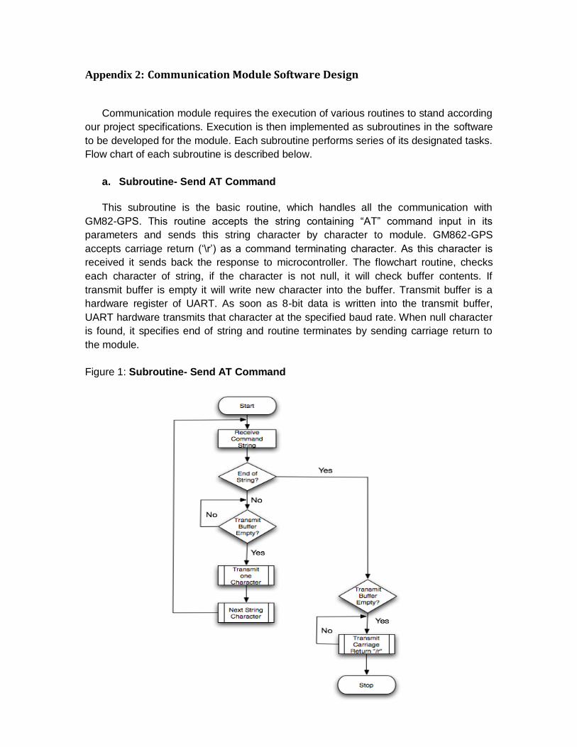
a. Subroutine- Send AT Command
This subroutine is the basic routine, which handles all the communication with
GM82-GPS. This routine accepts the string containing “AT” command input in its
parameters and sends this string character by character to module. GM862-GPS
accepts carriage return (‘\r’) as a command terminating character. As this character is
received it sends back the response to microcontroller. The flowchart routine, checks
each character of string, if the character is not null, it will check buffer contents. If
transmit buffer is empty it will write new character into the buffer. Transmit buffer is a
hardware register of UART. As soon as 8-bit data is written into the transmit buffer,
UART hardware transmits that character at the specified baud rate. When null character
is found, it specifies end of string and routine terminates by sending carriage return to
the module.
Figure 1: Subroutine- Send AT Command
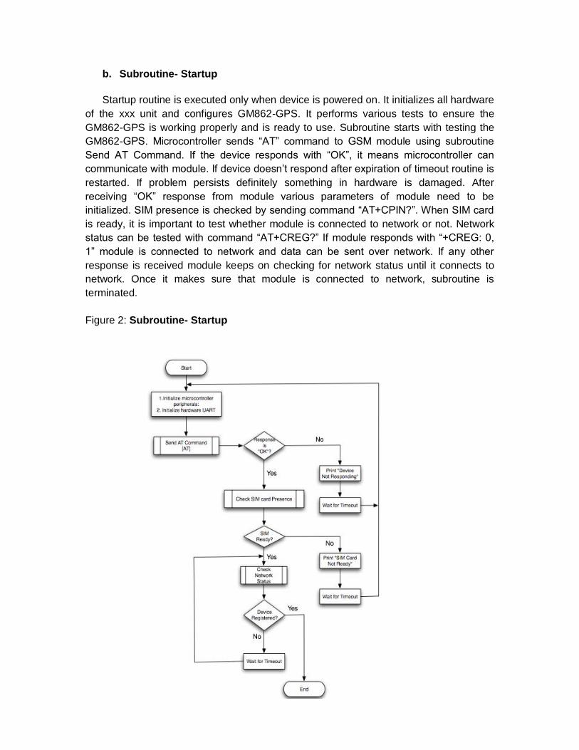
b. Subroutine- Startup
Startup routine is executed only when device is powered on. It initializes all hardware
of the xxx unit and configures GM862-GPS. It performs various tests to ensure the
GM862-GPS is working properly and is ready to use. Subroutine starts with testing the
GM862-GPS. Microcontroller sends “AT” command to GSM module using subroutine
Send AT Command. If the device responds with “OK”, it means microcontroller can
communicate with module. If device doesn’t respond after expiration of timeout routine is
restarted. If problem persists definitely something in hardware is damaged. After
receiving “OK” response from module various parameters of module need to be
initialized. SIM presence is checked by sending command “AT+CPIN?”. When SIM card
is ready, it is important to test whether module is connected to network or not. Network
status can be tested with command “AT+CREG?” If module responds with “+CREG: 0,
1” module is connected to network and data can be sent over network. If any other
response is received module keeps on checking for network status until it connects to
network. Once it makes sure that module is connected to network, subroutine is
terminated.
Figure 2: Subroutine- Startup

c. Subroutine- Read GPS Data
GPS controller is by default powered on when module is switched on. First step is to
check whether GPS controller is powered on by sending the command “AT$GPSP?” to
the module. If it responds with $GPSP: 0 it is not powered up. If it is not already powered
up; it can be switched on by sending “AT$GPSP=1” to the GM862-GPS module. Once
GPS controller is powered up location information can be read from it by sending
“AT$GPSACP”. The module responds with a long NMEA (National Marine Electronics
Association), standard protocol used by GPS receivers to transmit data sentence.
Information will be extracted from the received response and saved in formatted string.
This string can be later on passed to Send SMS subroutine to send it to remotely located
Tracking Server.
Figure 3: Subroutine- Read GPS Data

d. Subroutine- Send SMS (Short Message Service)
This subroutine accepts message string as input parameter, which needs to be
transmitted. Subroutine adds a terminating character Ctrl-Z at the end of message string.
The next step is to check whether module is in Text SMS mode, which can be checked
by sending command “AT+CMGF?” If module responds with “+CMGF: 0” it is in PDU
mode. Mode can be changed to text by sending command “AT+CMGF=1”. To send an
SMS module requires destination phone number that is sent to module using command
“AT+CMGS= da” where da represents the destination phone number. This phone
number will be read from microcontroller internal memory which is stored during
programming. After sending destination number module waits for prompt “>”. When
prompt appears message string is sent using Send AT Command subroutine. If
message sent successfully, module responds with +CMGS: <mr> where mr is message
reference number. If any error occurs subroutine tries to resend the message until it is
successfully sent.
Figure 4: Subroutine- Send SMS
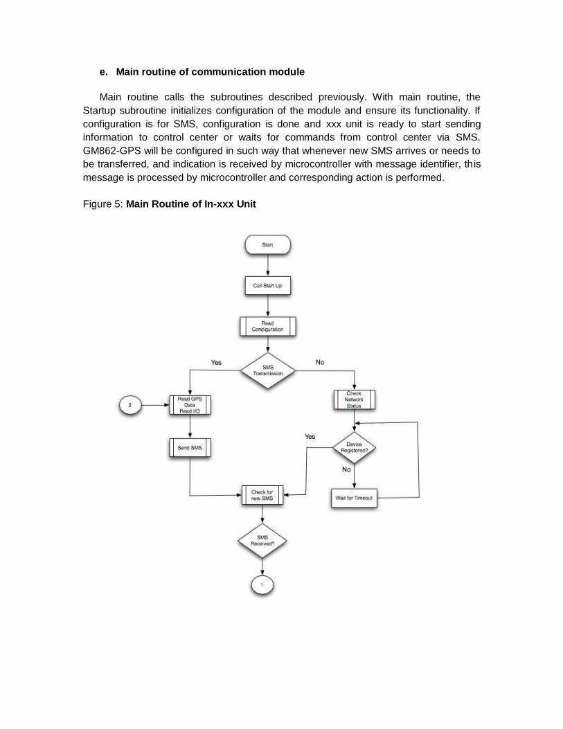
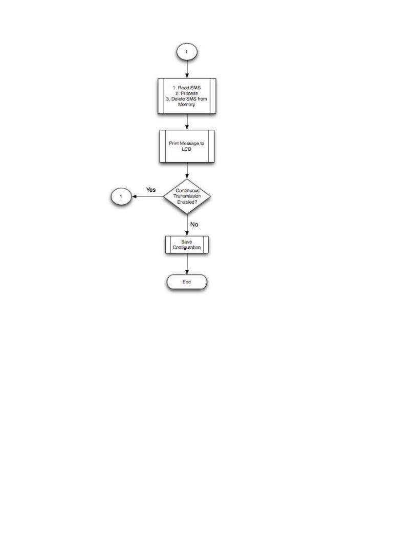
e. Main routine of communication module
Main routine calls the subroutines described previously. With main routine, the
Startup subroutine initializes configuration of the module and ensure its functionality. If
configuration is for SMS, configuration is done and xxx unit is ready to start sending
information to control center or waits for commands from control center via SMS.
GM862-GPS will be configured in such way that whenever new SMS arrives or needs to
be transferred, and indication is received by microcontroller with message identifier, this
message is processed by microcontroller and corresponding action is performed.
Figure 5: Main Routine of In-xxx Unit