tender document - engineering projectsengineeringprojects.com/tender/uploadfiles/2248_vol-iii... ·...
TRANSCRIPT

TENDER DOCUMENT
TENDER No.: BHI/PI(S)/665/1042
FOR
Tender for Supply, Fabrication, Erection & Painting of Structural Steel & Allied work for “Augmentation of Raw Material Receipt and Handling Facilities for New OHP, Part-B (Package No.-061), for Bhilai Steel Plant at Chhattisgarh.
VOLUME – III
(Tender Specifications)
ENGINEERING PROJECTS (INDIA) LIMITED
(A GOVT. OF INDIA ENTERPRISE)
B- 252, Street No.-5, Smriti Nagar, Bhilai,
Chhattisgarh- 490020

STEEL STRUCTURES
&
AUXILIARY FACILITIES
(CHAPTER-04)

STEEL AUTHORITY OF INDIA LIMITED
BHILAI STEEL PLANT
GENERAL TECHNICAL SPECIFICATION
FOR SUPPLY, FABRICATION, ERECTION
SHEETING & PAINTING OF STEEL STRUCTURES
(GS – 04)
MECON LIMITED
RANCHI - 834002
No. MEC/S/1901/11/38/0/00/00/F1889/R2
JULY, 2007
Sl.No. Description Page No.
1 Content sheet 1
2 Amendment sheet 2
3 General Description of Work 3,4
4 Scope of Work 4 to 6
5 Design of Building Structures 6 to 19
6 Design of Conveyor galleries & Junction
Houses
20 to 25
7 Pipe Line Supporting Structures 25 ,26
8 Steel Chimney 28
9 Standardisation and Uniformity 29
10 Fabrication of Steel Structures 30 to 42
11 Erection of Structures 42 to 50
12 Welding Specifications 50 to 56
13 Painting of Building Steel Structures 56 to 60
14 General Requirements 60 to 62
15 Inspection of Structures 62 to 64
16 Quality System and Third Party Inspection 64 to 71
17 Permissible Deviations in Assembly of
Welded Joints
71,72
18 Permissible Deviations in Erection and
Fabrication
72 to 83
General Technical Specification
CONTENTS
© 2007 MECON Limited All rights reserved
Structural
Page 1 of 83
GS-04

Sl. No. Description Page No.
General Technical Specification
AMENDMENT SHEET
© 2007 MECON Limited All rights reserved
Structural
Page 2 of 83
GS-04

General Technical Specification
SECTION : 1
GENERAL DESCRIPTION OF WORK
1.1 The general specifications for structural works furnished herein are intended
as guidelines for execution of the works satisfying the Owner‟s requirements
as also complying with all technical norms in totality. This specification is to
cover the design, preparation of design drawings and fabrication drawings,
supply of all labour as well as materials and construction of all structural
work on a turnkey basis for the Project / Works as described in the general
conditions of contract.
1.2
1.3
Description of various items of work under this specification and nature of
work in detail are given hereinafter. The complete work under this scope
is referred to as STRUCTURAL WORKS. The detailed scope of works
covered under Structural works is given in Section -2.
The work to be performed under this specification consists of design,
engineering , supply, fabrication, erection and cladding, as well as
providing all labour, materials, consumables, equipment, temporary
works, temporary labour and staff colony, constructional plant, fuel
supply, transportation and all incidental items not shown or specified but
reasonably implied or necessary for the completion and proper
functioning of the plant, all in strict accordance with the specifications,
including revisions and amendments thereto as may be required during
the execution of the work.
1.4 Supply of all materials including structural steel, roof cladding & side-
cladding sheets, fasteners, paints, consumables like gas, electrodes etc.
and all other materials as deemed necessary for proper completion of the
work, are included in the scope of the Contractor.
1.5 The work shall be carried out according to the design/drawings to be
developed by the Contractor and approved by the Owner/Consultant.
© 2007 MECON Limited
All rights reserved
Structural
Page 3 of 83
GS-04

General Technical Specification
For all buildings and structures, necessary layout and details are to be
developed by the Contractor keeping in view the statutory & functional
requirements of the plant and facilities and providing enough space and
access for operation, use and maintenance. Certain minimum
requirements are indicated in this specification for guidance purpose
only. However, the Contractor‟s offer shall cover the complete
requirements as per the best prevailing practices and to the complete
satisfaction of the Owner.
1.6
Contractor shall inspect the site, examine and obtain all information
required and satisfy himself regarding matters and things such as access
to site, communications, transport, right of way, the type and number of
equipment and facilities required for the work, availability of local labour,
materials and their rates, local working conditions, weather, tidal / flood
levels, subsoil conditions, natural drainage, etc. Ignorance of the site
conditions shall not be accepted by the Owner as basis for any claim for
compensation or extension of time. The submission of a bid by the
Contractor will be construed as evidence that such an examination was
made and any later claims / disputes in regard to price quoted shall not
be entertained or considered by the Owner on account of ignorance of
prevailing site conditions.
1.7. Contractor shall comply with all the applicable statutory rules pertaining
to Factory act, Fire safety rule of Loss prevention association, Water act
for Pollution control, Explosives act etc. Provisions of Safety, health and
welfare according to Factories act shall also be complied with. Statutory
clearances and norms of State Pollution Control Board shall be followed.
Statutory body /Act requirements shall be fulfilled by the Contractor and
in case any modifications /additions to the building /Structures are to be
made as per the above, shall be carried out by the Contractor at no extra
cost to the Owner.
SECTION - 2
SCOPE OF WORK
© 2007 MECON Limited
All rights reserved
Structural
Page 4 of 83
GS-04

General Technical Specification
2.0.
The scope of work shall cover , but shall not be exclusively limited to,
the following : - collection of all site related data & conducting site investigations,
- design, preparation of all design drawings, fabrication drawings,
- obtaining Owner‟s/Consultant‟s approval on general arrangements and
design of structures
- dismantling, retrieval, sorting and storing of any existing structures as
directed by the owner, if dismantling is a part of the total work
- supply of all materials viz, raw steel, sheeting for roof and side
cladding, and paints
- supply of fasteners like bolts, nuts, washers etc
-
supply of consumables like electrodes for welding, gases for gas
cutting etc
- supply of plant & machinery, tools tackles, instruments for fabrication
and erection
- providing facilities for testing of materials and conducting NDT
- providing facilities for transport and handling
- deploying requisite skilled and unskilled manpower
- making arrangements for all services like approach to site, electricity,
water etc
- fabrication of structures , their transport and proper storing at site
- erection of structures, claddings, gutters, down pipes etc
- application of paints at shop after fabrication and at site after erection
- providing all reasonable facilities for inspection by Owner/Consultant
- conducting NDT as stipulated by the Owner and making test results
available to Owner / Consultant for evaluation
© 2007 MECON Limited
All rights reserved
Structural
Page 5 of 83
GS-04
General Technical Specification
- compliance with primary acceptance tests / inspection, liquidation of
defects ; compliance with final acceptance tests / inspection, liquidation
of defects;
- carrying out field-engineering decisions as desired by the Owner
- preparation of “As Built” drawings for all the structures
and hand over to the Owner the completed structural work to
the Owner‟s full satisfaction .
- supply of all loading data for RCC foundation, layout drawing, HD bolt
insert details and all other necessary information for requirement of
Foundation/ RCC work , where future expansion is envisaged , the
successful contractor shall furnish load data separately for present and
future construction.
- any other work deemed incidental for the completion of the overall
work but not included in the above detailed scope.
SECTION – 3
DESIGN OF BUILDING STRUCTURES
3.0
3.1
3.1.0
3.1.01
General
This specification shall apply to steel work in building and general structural steel
work. For technological structures, additional stipulations shall be considered
as per technical requirements.
Design considerations
General
Structures shall be designed such that they are economical and safe and meet
the functional and service requirement of the technological process for which
© 2007 MECON Limited All rights reserved
Structural
Page 6 of 83
GS-04

General Technical Specification
they are designed. The architectural planning of the building shall be based on
technological requirements.
3.1.02
3.1.03
3.1.04
3.1.05
3.1.06
3.1.07
3.1.08
3.1.09
3.1.10
a)
b)
The structures shall be designed conforming to the relevant safety regulations,
Factory Acts, Electricity Rules and stipulations of Statutory bodies as
applicable to the project.
Natural ventilation shall be provided ensuring that it does not permit rain water
entry into the building. Scope of natural lighting shall be used to the maximum
possible extent. Mild steel gutters and down-pipes with gutter outlets having grating cover shall
be provided to carry rain water from roofs of buildings to the drainage system
at ground level. All gutters shall be designed as walkable with 600 mm sole
width. Adequate facilities in the form of monorails, hoists, platforms etc. shall be
provided to facilitate repair and maintenance of overhead cranes, equipment,
etc. Access to these platforms shall be provided by stairs / ladders from the
nearest accessible floor or platform.
Access to all floors, gangways and landings shall be by staircases. Access to
platforms and landing of secondary importance or where such access is used
only rarely, shall be by vertical ladders with safety hoops. Roofs with access shall be provided with safety handrails along the periphery
of the roof. Edges of floors, gangways, stairs and landings shall be provided with safety
hand railings.
At gable ends of buildings, platforms shall be provided connecting the
walkways at crane gantry level.
Floors, gangways and landings shall be covered as follows :
Gangways and landings shall have chequered plate with a minimum thickness
of 6mm o/p suitably stiffened to meet design load requirements.
Floors and operating platforms other than the above shall have chequered
plate flooring or hot dip galvanised open gratings , or RCC slab resting on
steel structural framework , to suit the technological requirements.
© 2007 MECON Limited All rights reserved
Structural
Page 7 of 83
GS-04
General Technical Specification
3.1.11
3.1.12
3.1.13
Protective metal heat shields shall be provided for steel structures exposed to
continuous heat radiation of temperature exceeding 150C and also where
hot metal splashing on structures is likely to occur. All buildings and their foundations shall be designed so that it shall be possible
to extend them in the longitudinal direction at a later date without further
strengthening of gable structures. Provision for transverse extension ,if any ,
shall also be made at the initial stage.
Sheeting on sides and gables shall generally terminate 3.0 m above ground
floor level unless required to be otherwise. Sides below this level shall be
generally screened by brick walls allowing sufficient air inlet to achieve natural
ventilation, unless otherwise required from technological / ventilation
requirements.
3.1.14 Connection by permanent bolts to structural elements subject to vibration shall be
provided with lock nuts.
3.1.15 For Analysis/ design of steel structural frame work STAAD PRO soft ware shall be
used . CD of input files shall be submitted to purchaser / consultant along with the
hard copy of the document.
3.2
3.2.01
Elements of Structures
Columns
a)
b)
c)
At the location of passage/opening through columns web shall be suitably
strengthened by vierendeel panel or modified lattice system. Shear force at the column base shall be resisted either by shear keys
shop-welded to the underside of column base plates or by welding base plate
to inserts provided in foundation. The level of underside of column base shall be so chosen such that the
complete anchor table lies below the finished floor level, thus keeping the
shop floor free from projections of anchor tables.
© 2007 MECON Limited All rights reserved
Structural
Page 8 of 83
GS-04
General Technical Specification
3.2.02
a)
b)
c)
d)
e)
f)
g)
h)
i)
j)
k)
3.2.03
Crane Girders
Crane girders shall generally be of simply supported design, unless continuous
crane girders are specifically required.
Top flange plate shall be welded to web plate with full penetration butt weld
with fully automatic submerged arc welding. Bottom flange plate shall be
welded to web plate by continuous fillet welds with automatic/semi-automatic
welding.
All intermediate stiffeners shall be fitted against top flange and welded to it by
fillet welds/partial penetration butt welds. These stiffeners shall terminate
short of bottom flange with at least 25 mm gap. The stiffeners shall be fillet
welded to web plate and corners shall be cut suitably to clear thermally
affected area of web to top flange connection.
End bearing stiffener plates of crane girder shall be capable of transmitting the
maximum reactions to the columns. The bearing surface of the bearing plate
shall be planed/machined to ensure full contact.
Tension flange of crane girders shall be stabilised by horizontal latticed
bracings, where required in order to limit the slenderness ratio of the flange to
150.
Generally for girders having span 12m and above, vertical auxiliary girder and
horizontal girder at crane girder bottom flange level shall be provided.
All crane girders shall be checked for fatigue as per IS: 1024 ( latest).
At crane girder level, walkway shall be provided on both sides. Walkway at
column location s shall have minimum clear width of 500mm. Approach by
staircase to this level shall be near the maintenance bay.
All crane girders and their supporting structures shall be designed for loading
from loaded crane in worst position of crab and crane to create most
unfavorable loading condition of the girders. For increase of load due to impact
and crane load combination including lateral surge shall be taken as per
provision of IS 875 ( Part – 2) -1987.
Suitable approach to be provided for tightening of bolts of Crane Rail .
Approach for Crane Rail fixing shall be properly planned for all types of
sections of Crane Girders.
Surge Girder walkways and auxiliary beams.
© 2007 MECON Limited All rights reserved
Structural
Page 9 of 83
GS-04
General Technical Specification
a)
b)
c)
Continuous maintenance walkways with safety hand-railing shall be provided
along each column row adjacent to each crane gantry girder. These
walkways shall be of non-slip plate construction connected to crane girder
top flange by continuous fillet welds. Staircase at every 120m shall be
provided from floor for access to this walkways so that stairs are available
within 60m from any location. Connections between surge girder and the main columns shall be designed to
resist load due to lateral braking of crane trolley. On the periphery of the building, full length handrails shall be provided along
the edge of the maintenance walkway at crane girder level.
d) Handrail and its clearance from crane end carriage shall conform to provisions
of relevant safety regulations.
3.2.04
a)
Crane Stops
Crane stops shall be provided at the ends of each crane girder system , or as
required to limit the movement of crane as per technological requirements.
b) Crane stops shall be bolted to crane gantry girder.
c) Only tested rail materials shall be used. Manufacturer‟s test certificate, including
chemical analysis shall be supplied.
d) Rails shall be free from twists, pitting, laminations and any other internal and
external defects. The rail shall be straight and the deviation from the
straightness shall not exceed + 1.5mm. If necessary the rail shall be cold
straightened.
e) Unless otherwise specified, the crane rail joint shall be butt-jointed( either by
Thermit or fusion welding) or by fishplates .
f) For Butt-welding the contractor shall take prior approval of the Purchaser
regarding method of edge preparation, welding procedure and sequence of
welding to be done. Edge preparation shall be done by oxyacetylene flame and
shall be neatly finished by chipping and grinding.
g) All position low hydrogen electrodes conforming to IS 814-1991 shall be used
for welding. The rail end shall be pre heated to 250 deg. C before welding. The
electrode shall be preheated as per manufacture‟ s instructions. The welded
joint shall be allowed to cool slowly. It is recommended that the initial and
intermediate layers of deposit may be by using ferron V , Superchord or
equivalent. Top 3mm layer shall be deposited with Duroid 2A or equivalent, to
obtain good wearing surface.
© 2007 MECON Limited
All rights reserved
Structural
Page 10 of 83
GS-04

General Technical Specification
h) The joints shall be free from kinks, twists etc, and shall be grinded properly after
welding to ensure smooth running of the crane.
i) Method of securing the crane rail to the crane gantry, alignment and expansion
joints , if any, shall be subject to Purchaser‟ s approval. The crane rail clips shall
be preferably forged or pressed from steel plates.
3.2.05
a)
b)
c)
Roof Structures
The main supporting element for roof shall be roof trusses provided at uniform
spacing to suit shop layout. Roof shall be provided with adequately sized roof
monitor for natural ventilation, wherever required.
Roof shall have suitable slope to meet technological as well as rainwater
drainage requirements. Hand railings at eaves level and gable ends of the
roof of the building shall be provided.
System of bracings shall be provided in the roof top chord and bottom chord
levels along with longitudinal ties to ensure stability and rigidity of the roof
structures. Vertical bracings between trusses shall also ve provided wherever
required.
d) Galvanised wind tie (45x6 mm flat) shall be provided at the free edge of roof
sheeting.
e) Suitable arrangement of anchors shall be provided at the ridge of roof sheeting
for holding lanyards of safety belts.
3.2.06
a)
b)
Roof lighting walkways
Full length roof lighting walkways, generally 600 mm wide, shall be provided in
each bay as required to match the number of rows of roof lights provided in
the shop as per technological requirement.
These walkways shall span between roof truss members and will be decked
with chequered plate floor. Walkways shall be provided with handrails on both
sides.
© 2007 MECON Limited
All rights reserved
Structural
Page 11 of 83
GS-04

General Technical Specification
3.2.07
a)
b)
c)
Roof drainage system
Roof drainage system shall be designed for maximum precipitation for 5
minutes based on local meteorological data. A factor of safety of 1.3 shall be
kept in the design.
All valley and eaves gutters shall be of pressed plate construction with a
minimum sole width of 600 mm so as to function as walkways. Eaves gutter shall be provided for eaves height ranging between 10 m to
25 m above apron/ground level.
d) The gutters shall be laid to slope towards down-pipes with welded outlets and
having grills fitted flush with gutter sole. Slope of gutters and collector pipes shall
not be flatter than the following limits :
i) Longitudinal slope of gutter 1 : 500
ii) Longitudinal slope of collector pipe 1 : 300
e) Poking holes with cover shall be provided in the down-pipes at suitable intervals
as well as at accessible levels, to clean the down-pipes.
f) Collector pipes shall be provided with covered manholes at 6 m intervals.
g) Eaves gutter shall be provided with safety handrails.
h)
When rain water falls from higher to lower roof, double layer of sheets shall be
provided for the portion of roof sheeting on which rain water falls, provided the
drop of roof is in the range of 3 m to 6 m. In case the drop is more than 6 m,
independent gutter shall be provided.
i) Down pipes shall be spaced preferably at 24 m centres. The down-pipes shall be
connected to the gutter with suitably designed hoppers with gratings at sole
level of gutter, made of 8 mm dia rounds at 50 mm centers.
j) Joints of gutter and collector pipes shall be by welding in order to be leak-proof.
© 2007 MECON Limited
All rights reserved
Structural
Page 12 of 83
GS-04

General Technical Specification
3.2.08
Wall Structures
a) Wall runners with necessary sag rod arrangements shall be provided to support
wall and gable sheeting, including internal partition wall, wherever required.
b) Hanging wall posts shall generally terminate at 3.5 m above ground floor level
unless required to be otherwise ( Refer Clause 3.1.13 ).
c)
d)
3.2.09
Gables of buildings shall have wall post spaced at intervals to suit bay width.
Walls shall be provided with louvres and translucent sheeting at appropriate
levels, to provide natural ventilation and lighting.
Floor Frameworks
a) Floor beams supporting vibrating equipment shall be designed to avoid resonant
frequencies. (Refer clause 3.3.01 (c))
b) Beams along-with framework, shall be provided with both horizontal and vertical
bracing (wherever permissible) to achieve overall rigidity.
3.2.10
Vertical bracings
a)
b)
c)
Vertical bracings shall be provided on all column rows for each expansion
block.
Vertical bracings shall extend from ground level to roof level and shall be
designed to transmit longitudinal forces i.e wind forces, crane tractive forces,
seismic forces etc. to the foundation. Below crane girder level, for two-legged columns, the bracings shall be of
twin system in the plane of each column leg, suitably tied or laced together.
3.2.11
Access staircase, walkways, platforms and ladders.
© 2007 MECON Limited
All rights reserved
Structural
Page 13 of 83
GS-04

General Technical Specification
a)
Wherever possible, access shall be provided by means of stairs.
b) All walkways and stairs leading to working platforms shall have minimum 1000
mm width of walkways/flight of stair.
c) All other walkways and stairs leading to areas for maintenance purpose, or due
to restriction of space, shall have a minimum width of 800 mm of
walkway/flight of stair, unless required otherwise.
d) Staircases shall be generally designed with slope of approximate 37.5 with the
horizontal. (in no case the slope shall exceed 40 with the horizontal).
Intermediate landings shall be provided wherever required such that vertical
rise of each flight does not exceed 3000 mm. Risers in one flight shall be
equally spaced.
e)
f)
g)
h)
i)
j)
Walkway floors and stair treads shall be designed with chequered plate ( or
non-slip type plates). Ribbed floor/treads may be provided wherever the
possibility of accumulation of dust exists, taking care that such provisions do
not crate a nuisance to the operating personnel on the shop floor.
Rise of treads in staircases shall not exceed 200 mm.
A minimum headroom of 2200 mm shall be provided over operating platforms,
visitor's galleries, or other areas with possibility of public gathering. In all other
platforms, walkways and stairs, a minimum headroom of 2000 mm shall be
provided. Only in special cases, local headroom of 1800 mm may be allowed
(i.e at intersection with structural members etc.).
Cat ladders shall be provided for access, wherever provision of staircase is
impractical due to limitations of space, or the access is required very
infrequently. Wherever the height of cat ladder exceeds 4.0 m, safety cage shall be provided.
Intermediate landing shall be provided to cat ladders such that vertical height
of single rise does not exceed 8.0 m.
Cat ladders shall be designed with following provisions :
i) Width of rung
ii) Minimum rise of rung
Maximum rise of rung
= 500 mm
= 250 mm
= 300 mm
iii) Minimum clearance from rung of ladder to back of cage (in case of caged
ladders) = 700 mm
© 2007 MECON Limited
All rights reserved
Structural
Page 14 of 83
GS-04
General Technical Specification
iv) Minimum clearance from the centre of cage all round
v) Slope of cat-ladders :
= 350 mm
I. For normal cat-ladders, slope shall be
horizontal.
within the range of 75-90 with the
II. For ship-type ladders (i.e cat-ladders with short side handrails) the slope shall
be within the range of 65-75 with the horizontal.
k)
l)
All walkways, platforms and stairs shall be provided with safety handrails. All
handrails shall be constructed with steel tubes / angles for posts, top and middle
rail and plates/sheets for toe plates. In case of stairs, the toe guards need not
be provided. The vertical height of hand-railings on walkways and stairs shall be minimum
1000 mm above floor level.
m) Hand-railing along edge of roof and gutters shall have a minimum height of 600
mm over top edge of gutters/sheets. In such hand-railings toe guards need not
be provided. (only top handrail and mid-rail shall be provided).
n)
3.3
3.3.01
Access to roof of the building shall be provided by means of staircases at
midway length of the building. Pair of staircases shall be provided with one at
the near end and the other at far end length of building. Approach to monitor
roof / high bay roof from the roof of the bay approachable by staircases at
midway length of the building shall be by means of staircase ( if height of roof >
3m ) or cat-ladder. Approach shall be provided on the roof of the building along
the cross-section of the building.
Design
Design of structures
a) Design of steel structures shall be done in accordance with IS:800-1984 or any
equivalent international code of practice that may be applicable.
b) Structures subjected to fluctuating/reversal of stress (eg. Crane girders) shall
be designed in accordance with IS:1024-1979.
c) Resonance in structures : Structures supporting vibratory/reciprocating
equipments shall be designed so as to obviate occurrence of resonance. The
ratio of applied frequency to natural frequency shall not lie within the range 0.7
© 2007 MECON Limited All rights reserved
Structural
Page 15 of 83
GS-04

General Technical Specification
to 1.5.
For wind load calculation the following data may be considered
- Basic wind speed ( Vb) at 10 M ht = 39 m/ sec.
- Risk co- efficient ( K1) = 1.0
- Terrain ht and Structure size factor(K2) shall be calculated with Category 2.
- Topography co- efficient ( K3) = 1.0
Seismic load- Structure shall be designed as per IS- 1893-(Part1) 2002.
3.3.02
Description of design loads
Loads considered in design shall allow fully for all aspects of :
i) Dead weight of structures, wall, floors, equipment, wiring, machinery, pipe-work,
cabling and any item of a permanent nature.
ii) Superimposed loads for roofs and floors plus any temporary machinery not
allowed within the general superimposed loads.
iii)
Crane loading.
iv) Temperature loads from process requirements because of the position of the
structure relative to the heat source or from support of mains, pipes etc.
subject to heat.
v) Maximum range of temperature variation for climatic conditions = ± 45C
vi) Dust load.
vii) Dynamic loads from screens and other such reciprocating machinery.
viii) Maintenance hoists on Runway beams.
ix) Wind Loads
x) Seismic loads
xi) From future extensions.
xii) Any special erection requirements.
xiii) Erection loads on floor and structures
3.3.03
Loading codes
© 2007 MECON Limited
All rights reserved
Structural
Page 16 of 83
GS-04

General Technical Specification
a)
All live loads shall be considered in accordance with IS:875(Part-2)-1987.
(Also refer clause 3.3.04)
b) Wind loads shall be in accordance with IS:875(Part-3)-1987 and any other
consideration specific to the site.
c) Seismic loads shall be in accordance with IS:1893- 2002.
d) Crane loading to be considered in design shall be as follows :
I. As per relevant clause of IS:800-1983.
II. IS:875(Part-2)-1987 for conditions not covered in IS:800-1983.3. unless more
severe loads have to be considered for technological/operational conditions.
e) Crane stopper shall be designed in accordance with clause 6.1.4 of IS:875
(Part-5)-1987.
f) In absence of any suitable provision for design loads, any other recognised
code of practice may be followed subject to prior approval of the Owner.
3.3.04
Additional Design Loads
Besides technological loads, all platforms, walkways, stairs etc. shall be designed
for the following live loads :
i)
ii)
iii)
iv)
v)
vi)
vii)
viii)
ix)
Walkways and Platforms :2 KN/m²
Visitor's galleries :4 KN/m²
Maintenance platforms :4 KN/m²
including crane level walkway.
Staircase and treads :4 KN/m²
Monorail walkways :4 KN/m²
Handrails : 0.75 KN/m run
(Horizontal)
Ladder : 0.9 KN
at middle of rung
Dust loads ( for buildings : 0.5 KN/m²
and structures located in
dusty zone)
All structures supporting : Overloading vibrating equipment by 25 % on
(motors, fans etc.) Static load unless specified otherwise of Equipment.
© 2007 MECON Limited All rights reserved
Structural
Page 17 of 83
GS-04

General Technical Specification
3.3.05
3.3.06
3.3.07
Combination of loads Various design loads considered shall be combined in accordance with clause
8.0 of IS:875(Part-5)-1987 to give the most severe loading condition for design of
structures.
Stress Enhancements
Permissible limits of stress may be increased wherever permissible, in
accordance with IS:800-1983. Limiting deflection
a) The deflection shall be limited in various elements of structures in accordance
with IS:800- 1984 (clause 3.13).
b) In addition, the following limitations in deflection shall be observed in design :
Vertical Deflection
i) Monorail track beams , main floor beams,
equipment supporting beams &
beams supporting brick walls
ii) Main roof trusses, roof girders
main floor beams in operating
platforms
iii) Secondary floor beams
Horizontal Deflection
i) Crane girders due to surge force:
(from one crane only).
: Span / 400
: Span / 400
: Span / 325 Span / 2000
ii) Main columns at crane rail level:
in transverse direction due to
action of crane surge (for surge force consider
one crane for single bay and one crane each
on adjacent aisles for multi-bay buildings)
H / 2500
iii) Open gantry for condition as in: H/4000 (ii) above.
© 2007 MECON Limited
All rights reserved
Structural
Page 18 of 83
GS-04

General Technical Specification
Where H = Height of Column from bottom of base plate to crane rail level.
c) All deflections shall be calculated without dynamic factor.
3.3.08
Camber
Wherever excessive deformation is likely to cause operational problem or is
aesthetically not agreeable, camber shall be provided to neutralise the effect of
deformation due to dead load plus 50 % of imposed loads.
3.3.09
Expansion joints
a) Longitudinal and transverse expansion joints shall be provided in buildings and
structures in accordance with IS:800-1984 (clause 3.14).
b)
3.3.10
Expansion joints shall be formed by providing double rows of columns, with
overhanging gantry girders, secondary roof and wall framing being detailed to
allow the maximum calculated movement for the specified temperature
variation.
Miscellaneous design requirements
a) The minimum thickness of structural steel elements shall be in accordance with
IS:800-1984 (clause 3.8). Minimum size angle shall be ISA50x50x6.
b) The diameter of structural bolts shall not be less than 16 mm except for those
securing roof and wall sheets, windows, doors and stitching of thin coverings.
For bolted joints, at least two bolts per joint shall be provided.
c)
The size of fillet welds shall not be less than 5 mm.
d) Main structural elements shall be welded continuously. Intermittent welding shall
be used only on secondary members which are not exposed to weather or
other corrosive influence.
e)
i)
Field connection and splices shall be made as follows :
by welding
© 2007 MECON Limited
All rights reserved
Structural
Page 19 of 83
GS-04

General Technical Specification
ii)
iii)
by permanent bolts (for secondary members such as purlins, wall
etc.)
by High Strength Friction Grip bolts (HSFG)
runners
3.4
DESIGN OF CONVEYOR GALLERIES AND
JUNCTION HOUSES
3.4.0
3.4.01
3.4.02
3.4.03
3.4.04
3.4.05
3.4.06
Design Considerations
The general parameters for conveyor galleries shall conform to the provision
of IPSS:2-03-001-81 (Interplant Standards : Steel Industry - Design
parameters for galleries and tunnels for belt conveyors in steel plant), and
provisions of IS : 11592-1985 unless specified otherwise in Technical
Specifications. The structures shall be designed so as to meet functional
requirements and shall provide space for operation, maintenance and removal
of machinery and give the workers good and safe environment.
Gallery floors shall be of pre-cast R.C.C slabs / Chequered plates ( as
required ) supported on steel beams.
Steps shall be provided (rise not exceeding 130 mm) along the walkways if the
gallery slope exceeds 12. In case the slope of gallery is between 6 to 12,
suitable ribs shall be provided on floor (without any sharp edges) at 250 to
300 mm intervals.
Provisions shall be made for emergency exit from galleries to ground level and
also for cross-over above conveyor at 100 m intervals (maximum). The width
of cross over shall not be less than 600 mm. Roof and side walls of conveyor galleries shall be covered with GCS/ Aluminium
sheets. with a provision of gap of 300 mm below roof and 150 mm from top of
floor level on the side wall for ventilation.
Adequate provision for natural light inside conveyor gallery shall be made
through side walls by providing translucent sheets (FRP sheets as per IS:
12866-1989). Every sixth sheet on side wall shall be FRP sheet and shall be
staggered on opposite wall.
© 2007 MECON Limited
All rights reserved
Structural
Page 20 of 83
GS-04

General Technical Specification
3.4.07
3.4.08
3.4.09
3.4.10
3.4.11
3.4.12
3.4.13
3.4.14
3.4.15
3.4.16
Roof slopes of conveyor galleries shall be 1:5 (1 vertical, 5 Horizontal).
The level of underside of the base plate of gallery supporting trestles shall be
300 mm above the average ground level of the surrounding area.
Protective hand railing shall be provided along gallery walkways, open
platform, stairways, landings, edges of walkways when the gallery is not
enclosed, and around erection openings, if any, to ensure safety of operating
personnel. Conveyor galleries longer than 150 m shall be provided with expansion joints
with twin trestles/supports. Each expansion block shall have fixed
support/rigid trestle with adequate arrangement (provision of top chord and
bottom chord bracing to gallery girder etc.) for transferring the transverse and
longitudinal forces to the foundation. Gallery girders near junction house shall be preferably supported on trestle
located as close to the junction house as possible, with part of gallery girder
between junction house and trestle cantilevered from the trestle. Supporting
gallery girders on junction house shall be generally avoided.
The underside of the belt conveyor shall be fully covered with 3 mm sheet in
case of conveyor is located within the boundaries of the plant. Wherever such
covering is not provided (as in case of the mines area or cross country), the
covering must be provided where the gallery crosses roads, railway lines or
areas of public gatherings.
Conveyor gallery over hot metal track :
When underside of gallery is at less than 12m height from track level, heat
shield shall be provided below gallery as well as on sides for a width of track
8 m ( i.e. 4 m on either side of center line of the track ).
When conveyor gallery crosses above or below H.T cables, a minimum clear
distance of 1.0 m between the structural elements/cladding and HT cables
shall be maintained.
When the conveyor bridge passes over plant roads, clearance between the
road surface and the lowest points of the bridges shall not be less than 4.5 m
or the height needed for the passage of the largest individual components of
the plant equipment, whichever is the larger. The junction house shall be designed to suit the technological requirements.
Number of floors, height of building etc. shall be decided accordingly.
© 2007 MECON Limited
All rights reserved
Structural
Page 21 of 83
GS-04

General Technical Specification
3.4.17
3.4.18
3.4.19
3.4.20
3.4.21
3.4.22
3.4.23
In general the junction house shall be designed as framed structures on shorter
span side and vertically braced on longer side to achieve stability.
Floor of junction houses shall be of RCC slab supported on steel beams, unless
required otherwise from technological consideration. The RCC slab will be
connected to steel beams through suitable lugs. Roof and side covering of junction houses shall be with GCS/Aluminium sheets
/ troughed colour coated sheets as specified. Roof slope shall be 1 : 5 ( 1
Vertical : 5 Horizontal).
Suitable access staircase and safety hand railing shall be provided to all floors
of junction houses. When hydro-washing of floor of junction house is envisaged , the floor beam
supporting RCC slab shall be laid to a suitable slope to achieve the same,
wherever the same is not practicable to achieve through screed concrete.
(Minimum slope of floor shall be 1.5%). Wall sheeting shall generally start from the lowest working floor and extend up
to roof level with louvres at each floor level to ensure adequate natural
ventilation. Monorails for maintenance hoists shall be provided for maintenance and repair
of various equipments located on the floors.
Components of structures
3.4.24
Gallery Trusses and Roof
a) Gallery truss shall be of latticed type construction and shall support roof (for
covered galleries) as well as floor deck supporting conveyor system.
b) The trusses shall be adequately braced at top and bottom chord level to transfer
the horizontal wind forces to end portals.
3.4.25 Stringer Beam
These beams shall be suitably spaced to support the conveyor stringer post and
shall deliver load to gallery trusses. Walkways on either side of the conveyor shall
also be supported on these stringer beams.
© 2007 MECON Limited
All rights reserved
Structural
Page 22 of 83
GS-04
General Technical Specification
3.4.26
Supporting Trestles Intermediate trestles shall be two legged and shall deliver loads from gallery
trusses to the foundations. In addition, four legged trestles shall be provided which
will act as fixed support to transmit all longitudinal forces between expansion block,
in addition to other forces.
3.4.27
Junction Houses
a) Floors - Floor beam layout shall be arranged to suit equipment layout as well as
equipment anchoring system.
b) Columns - In addition to loads from floor and roof, columns shall be designed to
transmit horizontal load due to belt tension/snapping of belts to the foundation.
3.4.28
3.4.29
Belt Tensioning Device
Suitable structures shall be provided to accommodate belt-tensioning device
which may be located either under the conveyor gallery or in the junction house
itself. Wall Structures
a) Wall runners with necessary sag rods shall be provided to support wall sheeting
in conveyor galleries and junction houses.
b) Wall sheeting and louvres - refer clause 3.2.08
3.4.30
3.5
3.5.0
Access stairs, walkways, platforms, ladders, hand railing etc. - These shall be
provided in accordance with clause 3.2.11 of this specification.
Design of Structures.
a) Design of steel structures shall be done in accordance with IS:800-1984.
b)
In absence of specified dynamic factor to be considered for the load from the belt
conveyor, a dynamic factor of not less than 1.3 shall be considered for the design
of floor beams and gallery girders.
© 2007 MECON Limited
All rights reserved
Structural
Page 23 of 83
GS-04

General Technical Specification
c)
d)
e)
3.5.1
Gallery trusses and stringers as well as floor beams of junction house shall be
checked for obviating occurrence of resonance and shall be designed in
accordance with clause 3.3.01(c).
For wind load consideration the following may be considered :
- Basic wind speed (vb) at 10 M ht = 39 m/ s.
- Risk co-efficient ( K1) = 1.0
- Terrain ht and structure size factor ( K2) shall be calculated with category 2.
- Topography co- efficient (K3 ) = 1.0
Seismic load – structure shall be designed as per IS 1893 ( Part 1) 2002. site is
located in zone II.
Description of loads and loading codes
3.5.01
3.5.02
3.5.03
3.5.04
3.5.05
a)
b)
c)
d)
3.5.06
a)
Unless specified otherwise hereinafter, all the live loads shall be considered in
accordance with IS:875 (Part-2)-1987.
Wind loads shall be considered in accordance with IS:875 (Part-3)-1987.
Seismic loads shall be considered in accordance with IS:1893-1984.
Live loads from conveyor on the gallery floor shall be as per conveyor suppliers
load data.
While designing the fixed support/rigid trestles in an expansion block of conveyor
gallery the following loads (in addition to wind load) shall be considered.
Forces due to difference in frictional resistance of top and return idle rollers of
conveyor.
Forces due to inertia of rollers at the time of starting of conveyor belt.
Break down load caused by snapping of belt (in case of multiple conveyors,
snapping of one belt at a time) shall be considered.
Special loads if any
Gallery girders and floor shall be designed for the following live loads, inclusive
of spillage loads on floors.
Walkway/Supporting beams for floor - 4.0 KN/m²
b)
Under the conveyor belt
- 0.75 KN/m²
© 2007 MECON Limited
All rights reserved
Structural
Page 24 of 83
GS-04

General Technical Specification
c)
3.5.07
a)
b)
3.5.08
Gallery girder, for floor load of - 3.0 KN/m²
Dust load on roof of junction house and conveyor galleries shall be considered
as follows :
For building and structures located at a distance of 300 m from the dust
producing units - 0.5 KN/m²
At a distance of 300 m to 800 m from the dust producing unit - 0.25 KN/m²
As per technological requirements, provision of supporting the following, and
load arising thereof shall be considered in the design of conveyor gallery.
a) Ventilation duct.
b) Electrical cables/cable racks.
c) Fire Fighting equipment.
3.5.09 Junction house floors shall be designed for the following loads :
a) Live load on floor - 4.0 KN/m²
b) Tension from conveyor belt
c) Load due to equipment located on floor.
d) Load due to jamming of chutes.
e) Erection loads anywhere on the floor.
3.5.10
Combination of loads
The various loads specified shall be combined in accordance with clause 8.0 of
IS:875 (Part-5)-1987 to give the most severe loading condition for design of
structures.
© 2007 MECON Limited
All rights reserved
Structural
Page 25 of 83
GS-04

General Technical Specification
3.5.11
Stress enhancements
Permissible limits of stress may be increased, wherever permissible, in
accordance with IS:800-1984.
3.5.12
a)
Limiting deflection
The deflection shall be limited in various elements of structures in accordance
with clause 3.13 IS:800-1984.
b) In addition following limitation in deflection shall be observed in design :
i) Gallery Trusses
ii) Top of End portal of
gallery truss
iii) Traverse deflection of
of top of supporting
Trestle
- Span / 400
- H / 325 where
H = Height of portal above beams
- H/1000 where
H = Height of trestle above foundation.
3.6
3.6.0
3.6.01
3.6.02
PIPLINE SUPPORTING STRUCTURE
Design considerations
Bridges shall be provided to support pipelines of smaller diameters for which
maximum permissible span is less than the distance between supporting
trestles.
Trestles which are designed to transmit longitudinal loads (along the length of
pipeline) to the foundation, shall be four legged construction. Other trestles
which transmit only the vertical load to the foundation shall be two-legged
construction.
© 2007 MECON Limited
All rights reserved
Structural
Page 26 of 83
GS-04

General Technical Specification
3.6.03
3.7
3.7.0
3.7.01
3.7.02
Access stair and platforms shall be provided for maintenance of equipment
installed in the pipeline (eg. valves etc.). Maintenance walkways with hand-
railing shall also be provided along the pipeline, wherever required. Provision
of access stairs, walkways platforms, hand-railing etc. shall conform to clause
3.2.11 of this specification.
Design of Structures
Design of steel structures shall be done in accordance with IS:800-1984.
Unless otherwise specified hereinafter, all live loads shall be considered in
accordance with IS:875 (Part-2) 1987.
Wind load shall be considered in accordance with IS:875 (Part-3)-1987.
3.7.03 Seismic loads shall be considered in accordance with IS:1893-2002.
3.7.04 In addition, pipeline, bridge and supporting trestle shall be designed for the
following loads :
a) Weight of liquid or condensate, as is appropriate for pipeline.
b) Weight of valves, compensators, fittings etc. in addition of self-weight of pipe.
c) Load due to thermal expansion of pipeline
3.7.05 Maintenance platforms shall be designed for a service load of 4 kN/sq.m
3.7.06
Combination of loads
The various loads specified shall be combined in accordance with clause 8.0 of
IS:875 (Part-5)-1987 to give the most severe loading condition for design of
structures.
3.7.07
Stress enhancements
Permissible limits of stress may be increased, wherever permissible, in accordance
with IS:800-1984.
3.7.08
Limiting deflection
© 2007 MECON Limited
All rights reserved
Structural
Page 27 of 83
GS-04
General Technical Specification
a) Deflection of gallery bridge structure shall be limited to Span/400.
b)
Traverse deformation of trestle shall be limited to H/1000 where H = Height of
trestle above foundation level.
c) The deflection of other elements of structures shall be limited in accordance with
clause 3.13 of IS:800-1984.
3.8
3.8.0
STEEL CHIMNEY
General
This specification shall apply to design of self supporting steel chimneys.
3.8.1 Design Consideration
a) Lining shall be provided in chimney shell as per technological requirements. In
the case of lined chimneys, checking for stress and resonance due to wind shall
be done for both the conditions i.e lined and unlined.
b) Annular platforms with minimum clear width of 1200mm shall be provided at
locations of environment monitoring equipment, in addition to the stipulations of
IS:6533 (Part-2)-1989. Landing/resting platforms to ladders shall be provided
at intervals not exceeding 10.00 M where annular platforms are provided at
intervals of height greater than 10.00 M.
c) Approach to platforms shall be with ladders with safety cages. (Refer Clause
3.2.11(j) of this specification.
d)
Chimneys shall be provided with adequate number of Painter's trolleys for
inspection and maintenance unless categorically agreed to otherwise with
Owner. In case where Painter's trolley is not provided, suitable alternative
facility shall be provided for inspection and maintenance.
e) Chimneys shall be fitted with helical strakes of three rail system, and shall be
strong enough to withstand the additional wind load from the strakes.
3.8.2 Design
a) Steel chimneys shall be designed in accordance with IS:6533(Part-2)-1989.
© 2007 MECON Limited
All rights reserved
Structural
Page 28 of 83
GS-04
General Technical Specification
3.8.3
b) Elements like platforms, hand-rails, ladders, anchor bolts etc. shall be designed
in accordance with IS:800-1984.
c) For wind and seismic refer clause 3.3.01 (d) and (e) .
Limiting Deflection
The maximum deflection at the top due to the action of wind, without considering
the dynamic factor shall not be greater than h/200, where h is the unsupported
height of the chimney.
3.9
3.9.0
General
STANDARISATION
AND
UNIFORMITY
Every endeavour shall be made to achieve standardisation and uniformity
amongst the steel structures of different units of the plant.
3.9.1
The following items shall be kept in view in design of structures :
a) Uniform layout module shall be adopted to the extent possible consistent with
economy. It is suggested to adopt a basic module of 3 m for building width
and 6 m for column spacing along building length. b) Uniform slopes of roofs matching with existing buildings unless specifically
required otherwise for any particular unit.
c)
d)
Provision of expansion joints by using twin columns.
Uniform adoption of clearance between structures and moving parts of
equipment.
e) Provision of adequate natural ventilation by using louvres (canopy like
structures) at appropriate location and roof monitors/natural ventilation systems
at roof.
© 2007 MECON Limited All rights reserved
Structural
Page 29 of 83
GS-04

General Technical Specification
4.0
4.1
4.1.1
4.1.2
4.1.3
FABRICATION OF STEEL STRUCTURES
Drawings
The Contractor shall prepare design drawings indicating general
arrangement, members, sections and details of important joints,
fabrication drawings, erection drawings, bill of materials, drawing
office despatch lists / shipping documents, schedule of bolts and nuts
and as built drawings. All drawing work shall be in metric system and all
writing work shall be in English. Drawings shall be prepared using
Autocad software.
The fabrication drawings shall show full length layout with all connecting
members and connections marked thereon. The fabrication drawings
shall include all the necessary blown-up details required for the correct
fabrication of the structures to meet the design requirements. These
drawings shall be made in conformity with the best modern practices and
with due regard to speed and economy in fabrication and erection. Each
erection piece shall be clearly identified by an erection mark in these
drawings.
The preparation / detailing of fabrication drawing shall be complete in all
respects. In the case of bolted connections, the bolt dia., the hole dia.,
© 2007 MECON Limited All rights reserved
Structural
Page 30 of 83
GS-04
General Technical Specification
the actual location of holes and the coordinating scheme with
connecting/ matching elements shall be clearly indicated. As far as
possible, uniformity in the bolt dia shall be maintained. Where HSFG
bolts are used, method of surface preparation shall be indicated. In case
of welded constructions, the size and length of welds along the
relevant weld lines should be distinctly marked. The length
specified shall be the effective length excluding end crates. For all butt
welds, details of appropriate edge preparation shall be indicated.
4.1.4
4.1.5
4.1.6
4.1.7
4.1.8
4.1.9
Detailing of structural steel members subjected to dynamic loading shall
be so as to keep the stress concentration to a minimum. Cross welding
shall be avoided as far as practicable. For bolted connections subjected to dynamic loading, lock nuts or spring
washers shall be used in addition to plain washers. Erection drawings shall consist of line diagrams showing every detailed
member in position with the respective erection mark. Erection marks
shall appear on the left end of the members as detailed. All steel
members shall be erected with marks in the same relative position as
shown in plan or elevation. All loose members shall either be given part
marks or wired on to the main erection mark for despatch.
The erection clearances for cleat-connected ends of members
connecting steel to steel shall preferably not be greater than 10 mm. at
each end. The erection clearance at ends of beams shall not be more
than 20mm. at each end but where for particular reasons greater
clearance is necessary, suitably designed seats shall be provided.
The fabrication drawings shall be prepared in such a manner that
structures are despatched with maximum transportable lengths and work
involved at site is minimum. Steelwork shall be shop-fitted and shop-
assembled as far as practicable.
All edge preparations for welding shall conform to IS:9595.
4.1.10 The contractor shall ensure correctness & completeness of fabrication
drawings.
4.2
Material of Construction
© 2007 MECON Limited
All rights reserved
Structural
Page 31 of 83
GS-04

General Technical Specification
4.2.1
All steel and other materials used for steelwork and in association with
steelwork shall conform to appropriate Indian standards. Only tested
materials shall be used unless written authority is obtained for the use of
untested materials for certain secondary structural members. Unless otherwise specified in the drawings
a)
b)
c)
All rolled sections and plates up to & including 20 mm thickness
shall conform to Grade "A” as per IS : 2062. Plates of thickness above 20 mm and Plated structures subjected
to dynamic loading shall conform to Grade "B” as per IS: 2062. For High Tensile steel requirements, material conforming to
IS:8500 or SAIL- MA (HYA or HYB) shall be used.
4.2.2
4.2.3
4.2.4
4.2.5
Steel sheets shall conform to IS : 1079.
Steel tubes for structural purpose shall conform to IS : 1161 (of Grade Yst 240)
Corrugated Galvanised Sheets shall conform to IS:277 with appropriate Zinc
coating for the selected thickness of sheet on roof and sides. Aluminium industrial toughed sheets conforming to IS : 1254 shall be used as
follows : i) In roof - 0.91mm thick
ii) In side walls - 0.71mm thick
4.2.6
Translucent sheets shall be fibreglass reinforced polyester sheets
matching profile as per IS:12866.
of
4.2.7
Colour coated sheets shall be as per appropriate standard. All roof
,monitor roof galvanised / zinc aluminium colour coated sheets of total
coated thickness (TCT) of 0.65 mm with base metal yield strength of
240 MPa or alternately sheets having TCT of 0.5mm with base metal
yield strength of 550 MPa.
All side sheets , monitor sides colour coated sheets of total thickness
(TCT) of 0.6 mm with base metal yield strength of 240 MPa or alternately
sheets having TCT of 0.5mm with base metal yield strength of 550 MPa.
Ridging/ Flushing : colour coated sheets TCT of 0.8 mm with base
metal yield strength of 240 MPa or alternately sheets having TCT of 0.5
mm with base metal yield strength of 550 MPa. For all above, minimum
zinc deposition shall be 150 gms per sq.m.
© 2007 MECON Limited
All rights reserved
Structural
Page 32 of 83
GS-04

General Technical Specification
4.2.8
4.2.9
Gutters shall be of copper bearing steel conforming to Grade "A" as per
IS :2062
Crane Rails shall conform to IS : 3443.
4.2.10 All black bolts, nuts and locknuts shall conform to IS : 1363 and IS :
1364 (for precision and semi precision hexagonal bolts) of property
class 6.4 unless otherwise specified. Washers shall conform to IS : 6610
4.2.11 All tapered washer shall be as per IS:5372 for channels, and IS:5374 for
Joists. Spring washers shall conform to IS:3063.
4.2.12 All HSFG bolts shall conform to IS : 3757. Assembly of joints using
HSFG bolts shall conform to IS : 4000. Nuts and washers for HSFG bolts
shall be as per IS:6623 & IS:6649 respectively.
4.2.13 Covered electrodes for arc welding shall conform to IS: 814. Coding of
electrodes shall be as follows :
a)
b)
ER421 „C‟ X for mild steel of Grade 'A‟ and Grade 'B‟ as per IS :
2062
EB 542 „C' H3X for Mild steel of Grade 'B‟ as per IS 2062 for
dynamically loaded structures (arising out of crane, vibratory
screen, equipments etc.) „C' is the value of the current as
recommended by the electrode manufacturer.
4.2.14 Certified mill test reports of materials used in the work shall be made
available for inspection by the Owner / Consultant upon request.
4.2.15 All materials shall be straight and if necessary before being worked shall
be straightened and / or flattened by pressure including de-coiling of
plates unless required to be of curvilinear form and shall be free from
twists.
4.2.16 The MS / GI gratings shall be electro-forged and shall be of approved
brand and manufacturer unless otherwise agreed to by the Owner.
The type of grating selected shall be based on the loading in the area in
which the grating is provided and shall be subject to approval of Owner.
4.3
Material preparation
© 2007 MECON Limited All rights reserved
Structural
Page 33 of 83
GS-04

General Technical Specification
4.3.1 Cut edges shall be finished smooth by grinding or machining wherever
necessary. Sufficient allowance (3 mm to 5 mm ) should be kept in the
items in case machining is necessary.
4.3.2 Cutting may be effected by gas cutting, shearing, cropping or sawing. In
gas cutting of high tensile steel, special care is to be taken to leave
sufficient metal to be removed by machining so that all metal that has
been hardened by flame is removed.
4.3.3 Sufficient shrinkage allowance (@ 1mm/M) shall be kept wherever heavy
welding is involved.
4.3.4
Straightening and bending shall be done in cold condition as far as
practicable.
4.3.5 If required, straightening and bending may be done by application of heat
between 900C and 1100C. Cooling down of the heated item shall be
done slowly.
4.4
4.4.1
Drilling and punching of holes
Drilling and punching of holes for bolts shall be done as per clause
no.11.4.4 of IS:800:1984, unless otherwise specified by the Owner.
4.4.2 Drifting of holes for bolts during assembly shall not cause enlargement of
holes beyond permissible limit or damage the metal.
4.4.3 Holes for bolted connection should match well to permit easy entry of
bolts. Gross mismatch of holes shall be avoided.
4.4.4 Permissible deviation in holes for mild steel bolts of normal accuracy and
high strength bolts are given in the ANNEXURE-A.
4.5
Assembly for fabrication
© 2007 MECON Limited All rights reserved
Structural
Page 34 of 83
GS-04
General Technical Specification
4.5.1
Fabrication of all structural steelwork shall be in accordance with
IS:800-1984 and in conformity with various clauses of this specification,
unless otherwise specified in the drawings.
4.5.2 Fabrication of structures shall preferably be taken up as per the sequence
of erection.
4.5.3 All erection units shall bear erection mark no. and reference drg no. at a
prominent location on the structures for easy identification at site.
4.5.4
Fabricated structures shall conform to tolerance as specified in this
standard and in IS:7215-1974. In case of contradiction, tolerances
specified in this standard shall prevail.
4.5.5 All the components of structures shall be free from twist, bend, damage
etc,
4.5.6 Assembly of structures shall be carried out by using suitable jigs and
fixtures in order to obviate distortion during welding.
4.5.7 Cutting of items specially for truss, bracing, bunker, hopper, galleries
surge girder, portal etc, shall be done only after checking of sizes as per
Layout.
4.5.8 Surface, wherever machining is specified , shall be either planed or milled
or ground to ensure maximum contact.
4.5.9
If end-milling or machining is planned after the assembly is over,
sufficient allowance (5 mm to 15 mm) shall be kept in the items where
milling/machining is to be done.
4.5.10 If pre-bending of the plate is required to avoid welding distortion, it shall
be done in cold condition.
4.5.11 Sufficient trial assembly of fabricated components (despatch elements)
shall be carried out in the fabrication works to control the accuracy of
workmanship.
4.5.12
Where necessary, washers shall be tapered or otherwise suitably
shaped to give the heads of nuts and bolts satisfactory bearing.
4.5.13 The threaded portion of each bolt shall project through the
by one thread.
nut at least
© 2007 MECON Limited All rights reserved
Structural
Page 35 of 83
GS-04
General Technical Specification
4.5.14 Tolerance of assembled components of structures are given in TABLE -
4.5.15 Permissible deviations from designed (true) geometrical form of the
despatch elements shall be in accordance with IS:7215-1974.
4.6
4.6.1
4.6.2
4.6.3
4.6.4
4.6.5
4.6.6
4.6.7
Method of Construction
The method of construction shall be either by welding or by bolting
limiting the site work to the minimum possible.
Bolt diameter shall not be less than 16mm. except for bolts securing
roof and wall sheeting, windows, doors and stitching of thin coverings.
For bolted joints, min. two bolts shall be used.
The size of fillet welds shall not be less than 5mm for load-bearing
joints.
Main structural elements shall be welded continuously. Intermittent
welds shall be used only on secondary members, which are not exposed
to weather or other corrosive influence. Connections and splices shall be made by welding, or by bolting with
appropriate property class.Black bolts shall be used in connections
and attachments of secondary members such as purlins, wall girts, etc.
Bolts shall be prevented from loosening by means of lock nuts, single
coil spring washers or similar devices. Method of splicing shall be similar to the method of construction adopted
for structures. All splices shall be full-strength splice unless exception is
specified.
Roof and wall sheets shall be fixed to purlins and wall girts by stainless
steel top speed screws/galvanized J- hook bolts, each complete with
neoprene and stainless steel /galvanized washers. The connections
shall ensure water-tightness into the buildings. The spacing of these
screws/bolts shall be sufficient to prevent uplift of sheets by suction. The
roof and wall sheets shall be stitched together at their edges by using
studs, rivets or screws. The end and side overlaps of sheeting shall be
sufficient to prevent ingress of rainwater. End lap shall not be less than
75mm and side lap shall not be less than one and half corrugation for
© 2007 MECON Limited All rights reserved
Structural
Page 36 of 83
GS-04

General Technical Specification
GCS sheets. For troughed aluminium
recommendations shall be followed.
sheets
manufacturer‟s
4.7
4.7.1
4.7.2
4.7.3
4.7.4
4.7.5
4.7.6
Structural steel connection
The Contractor shall be responsible for the design and the detailing of all
connections. The design of connections shall provide for adequate
strength for the transfer of force in the structural elements indicated on
the design drawings. For purposes of detailing of connections, the
allowable stresses in material, bolts and welds shall be as per IS:800
and IS:816 or as specified in the design drawings. For all full strength butt welding of plates and sections thicker than or
equal to 10 mm, edge preparation shall be done and got approved by
the Owner / Consultant. Two numbers of washers shall be used for all bolted connections, one
washer bearing against the head and other bearing against the nut. The magnitude of forces shown on design drawings shall be used at
face values with no reductions for connections. If extra joints are to be provided in column, crane girder etc, prior
approval on the same shall be obtained from the Owner / Consultant
However , as general guidance, the following is suggested :
- Splice joint on column and crane girder shall be of full strength
butt weld, and, wherever possible, shall be located at the section
of minimum or substantially lesser stress.
- Splice joints of web and flange should be sufficiently staggered
in position. All penetration for piping, conduit, cable trays, etc., through grating or
plate flooring shall be cut and suitably banded in the field, except when
such penetrations are dimensioned in the drawings in which case they
shall be shop cut and banded.
© 2007 MECON Limited
All rights reserved
Structural
Page 37 of 83
GS-04

General Technical Specification
4.8
4.8.1
4.8.2
4.8.3
4.8.4
4.8.5
4.8.6
4.8.7
4.8.8
Fabrication
Fabrication of all structural steelwork shall be in accordance with IS:800
or their equivalent foreign national standard of the country of origin of
supply unless otherwise specified, and in conformity with various clauses
of the Technical Specification. Wherever practicable and wherever perfect matching of parts is required
at site, members shall be shop assembled before despatch to minimise
site work. Parts not completely assembled in the shop shall be secured,
to the extent possible, to prevent damage during despatch. All pieces shall be properly identified and bundled for transportation to
work site. Care shall be exercised in the delivery, handling and storage
of material to ensure that material is not damaged in any manner.
Materials shall be kept free of dirt, grease and foreign matter and shall
be protected from corrosion. All materials shall be stored properly on
skids above the ground which shall be kept clean and properly
drained. Girders and beams shall be placed upright and stored. Long
members such as columns and chord members shall be supported on
skids spaced near enough to prevent damage due to deflection.
Bolts shall be furnished according to bolt lists showing the location of their
use and additional bolts shall be supplied to cover wastage.
All fabricated pieces shall bear erection mark numbers painted/punched
according to appropriate erection and shop drawings at a prominent
location on the structure for easy identification. All workmanship shall be in accordance with the best practice in modern
structural shops. Greatest accuracy shall be achieved in the
manufacture of every part of the work and all identical parts shall be
strictly interchangeable. Shearing or flame cutting may be used at the Contractor's option
provided that a mechanically controlled cutting torch is used for
flame cutting and that the resulting edges are clean and straight. Unless clean square and true to shape all flame cut edges shall be
planed/cleaned by chipping or grinding. Where machine flame cutting is
permitted for high tensile steel, special care shall be taken to leave
sufficient margin and all flame hardened material shall be removed by
machining/edge grinding.
© 2007 MECON Limited All rights reserved
Structural
Page 38 of 83
GS-04

General Technical Specification
4.8.9
Wherever shearing is used for cutting to size, sheared members shall be
free from distortions at sheared edge.
4.8.10 The ends of all girder stiffeners shall be in contact with the compression
flange and shall be planed or ground to fit tightly against flange plates
unless otherwise stated on the drawings. Care shall be taken to ensure
full bearing of the stiffeners at the supports by machining the contact
surfaces of both bearing stiffeners and bearing plates. The ends shall
not be drawn or caulked.
4.8.11 Column splices and butt joints of struts and compression
members depending on contact for stress transmission shall be
accurately machined and close butted over the whole section with a
clearance not exceeding 0.1 mm locally at any place.
4.8.12 In column cap and bases, the ends of shafts, should be accurately
machined so that the parts connected butt over the entire surface of
contact. Care should be taken so that these connecting members are
fixed with such accuracy that they are not reduced in thickness by
machining by more than 1.0 mm. On secondary members, where
sufficient gussets and welds are provided to transmit the entire loading,
the column ends may not be machined subject to the approval of the
Owner / Consultant.
4.8.13 Holes for permanent black bolts shall not be more than 1. 5 mm larger
than the nominal diameter of the black bolts unless specified otherwise.
All holes for turned and fitted bolts shall be sub punched or drilled and
reamed at site under assembly of connected parts to a tolerance of +0.3
mm unless specified otherwise.
Holes in purlins, side-sheeting runners, packing plates and lacing bars
may be punched full size. Holes in light framing with the exception of
joint holes, may be punched full size. All punching and sub-punching
shall be clean and accurate and all drilling free from burrs. In
block/batch drilling, parts shall be separated after drilling and the burrs
removed. No hole shall be made by gas cutting process.
4.8.14 The component parts shall be so assembled that they are neither twisted
nor otherwise damaged and specified cambers, if any, shall be provided.
No drifting of hole shall be permitted except to draw the parts together.
Drifts used shall not be larger than the nominal diameter of the bolt.
Drifting done during assembling shall not distort the metal or enlarge the
holes. Sufficient trial assembly shall be carried out in the fabrication
works to prove the accuracy of workmanship of the and the number of
such trials required shall be at inspector's discretion.
© 2007 MECON Limited All rights reserved
Structural
Page 39 of 83
GS-04

General Technical Specification
4.8.15
Where necessary, washers shall be tapered or otherwise suitably
shaped to give the heads and nuts of bolts a satisfactory bearing. The
threaded portion of each bolt shall project through the nut by at least one
thread.
4.8.16 In all cases where the full bearing area of the bolt is to be developed, the
bolt shall be provided with a washer of sufficient thickness, under the nut
so as to avoid any threaded portion of the bolt being within the thickness
of the parts bolted together. Column bases and caps, shall be in one
solid piece, and except when cut from plates with true surfaces, shall be
accurately machined over the bearing surfaces, and shall be in effective
contact over the whole area of the machine end of the stanchion.
4.8.17 Each piece shall be distinctly marked before delivery, in accordance with
an approved marking diagram and shall bear such other marks as
well to facilitate erection. For easy identification at site a small
distinguishing mark for each building shall be painted at each end of
every member before despatch from fabrication shop. The fabricated
steel work shall be despatched in sequence as per agreed programme
and for such portion as may be found convenient for erection or as
ordered by the Owner / Consultant.
4.8.18
4.8.19
The Contractor shall provide suitable packing wherever necessary to
guard against damage during handling and transportation to site. All
fabricated parts shall be adequately braced to prevent damage during
transit.
The tolerances for fabrication of steel structures shall generally conform
to IS:7215 and to suit the technological requirements as specified by the
equipment supplier.
4.8.20 Any fabrication work which is considered not to be in keeping with the
Technical Specification forming the Contract, or in absence of Technical
Specification with recognized good practice, shall be rectified /replaced
/corrected at the Contractor's expense as directed by the Owner /
Consultant. Site fabrication work shall also conform to all specifications,
stipulations, terms and conditions applicable for shop-welded structures
as mentioned above.
4.8.21 Fabrication of steel structures shall not be allowed inside the plant
premises.
4.9
Wastage & Accountability
© 2007 MECON Limited
All rights reserved
Structural
Page 40 of 83
GS-04

General Technical Specification
4.9.1
For the purpose of accounting of materials where the same is supplied by
the Owner, free or on cost recoverable basis, the following wastage
including rolling margin, invisible wastage and cut pieces of less than
one metre length and plates with lesser dimension less than 300 mm
shall be allowed.
a) Structural Steel : i) Sections - 5% on the quantity by weight
computed, based on Fabrication drgs.
ii) Plates - 7.5% on the quantity by weight
computed, based on Fabrication drawings.
b) Other materials : 5% on the quantity by weight computed, based on
manufacturing drawings.
For all cut pieces ( plates & sections ) invisible wastage (cutting and
burning losses) of maximum 0.5% will be admissible.
4.9.2 Owner reserves the right to take back such sections or quantity of steel
issued in excess of quantity as per fabrication drawings plus permissible
wastage where raw steel is issued free of cost by Owner. The contractor
shall return to the Owner all such steel supplied in good and acceptable
condition. In case of failure of the Contractor to return such surplus steel
on demand by the Owner , Owner reserves the right to recover the cost of
such steel at a penal rate of twice the SAIL- Stockyard rate of that
particular section of steel as on the date of accountability.
4.9.3 If the Contractor fails to return scrap / wastage generated as per the
percentage mentioned at 4.9.1. recovery on account of such scrap /
wastage shall be made by the owner at prevailing rate of steel+ 20 pc per
tonne.
The charging of penal rate shall be without prejudice to any other
remedies or action ,available to the Owner, against the Contractor.
4.10
4.10.1
Despatch Instructions
Each despatchable structure shall bear mark no. along with reference
drawing number at two prominent locations (e.g. on flange and bottom of
base plate of a column).
4.10.2 "As built" drawing shall be prepared after fabrication is completed to
indicate additions / alterations made during the process of fabrication.
© 2007 MECON Limited All rights reserved
Structural
Page 41 of 83
GS-04

General Technical Specification
4.10.3 Control assembly of important structures shall be done in the shop floor
before despatch to avoid mismatching. For all such important structures,
match marking shall be given at the control assembly stage in the shop
floor and such match markings shall be made clearly visible while
assembling the structures at site.
4.10.4 Centre lines of column flanges and both sides of web shall be punched,
preferably at top and bottom to facilitate alignment after erection.
5.1
5.
ERECTION OF STEEL STRUCTURES
Scope The scope of work under erection includes in addition to provision of
erection and transport equipments, tools and tackles, consumables,
materials, labour and supervision, the following:
a)
b)
c)
d)
Storing and stacking at site of erection of all fabricated structural
components/ units/assemblies till the time of erection. Transportation at site of structures.
Receiving at site of structures including site handling /movement,
unloading, storing and stacking at site of erection of technological
structures such as bunkers and the related structures All minor rectification / modification such as :
i) Removal of bends, kinks, twists, etc. for parts damaged during
transportation and handling;
ii) Cutting chipping, filing, grinding, etc., if required, for preparation
and finishing of site connections;
© 2007 MECON Limited All rights reserved
Structural
Page 42 of 83
GS-04

General Technical Specification
iii)
iv)
Reaming for use of next higher size bolt for holes which do not
register or which are damaged.
Welding of connections in place of bolting for which holes are
either not drilled at all or wrongly drilled during fabrication.
e)
Other rectification work such as
i)
ii)
iii)
iv)
Re-fabrication of parts, damaged beyond repair during
transportation and handling or incorrectly fabricated.
Fabrication of parts omitted during fabrication by oversight or
subsequently found necessary.
Plug-welding and re-drilling of holes which do not register and
which cannot be reamed for use of next higher size bolt.
Drilling of holes which are either not drilled at all or are drilled
at incorrect position during fabrication.
f)
g)
h)
i)
j)
k)
l)
m)
Fabrication of minor items/missing items or such important items as
directed by the Owner Consultant.
Assembly at site of steel structural components wherever required
including temporary supports and staging.
Making arrangements for and providing all facilities for conducting
ultrasonic X-ray or gamma ray tests on welds; getting the tests
conducted by reputed testing laboratories, making available
test films/ graphs, reports and interpretation.
Rectifying at site, damaged portions of shop primer by cleaning and
touch-up paint.
Erection of structures including making connections by bolts/high
strength friction grip bolts / welding.
Alignment of all structures true to line, level plumb and dimensions
within specified limits of tolerances as per IS :12843 “Tolerance for
Erection of Steel Structures”.
Application of second coat of primer paint and two coats of finishing
paint at site after erection.
Grouting of all column bases after proper alignment of columns
and only after obtaining clearance from Owner / Consultant.
n) Supply of labour in sufficient numbers,
directed by the Owner / Consultant.
where necessary, as
o) Conducting preliminary
tests.
acceptance and final acceptance
© 2007 MECON Limited
All rights reserved
Structural
Page 43 of 83
GS-04

General Technical Specification
p)
Preparation of as built drawings, preparing of sketches/drawings to
suit field engineering decisions, availability of material,
convenience of fabrication, transportation and erection and
changes during fabrication and erection.
All such works are subject to approval by the Owner / Consultant.
5.2
5.2.1
5.3
5.5.1
5.5.2
5.5.3
5.5.4
5.4
Erection Drawings
The erection drawings prepared by the Contractor and any approved
arrangement drawings, specifications or instructions accompanying them
shall be followed in erection of structures and miscellaneous connected
items throughout the project. Storing and Handling
The fabricated materials on receipt at site shall be carefully unloaded,
examined for defects, checked , stored out for each building and
stacked securely on skids above level ground which shall be kept clean
and properly drained. Girders and beams shall be placed upright and
stored. Long members, such as columns and chord members, shall be
supported on skids spaced near enough to prevent damage from
deflection. The fabricated materials shall be verified with respect to markings on the
marking plan or shipping list which shall be supplied by the Contractor. Any material found damaged or defective shall be stacked separately
and the damaged or defective portions shall be painted in distinct colour
for identification. Such materials shall be dealt with as ordered by the
Owner / Consultant. The handling and storing of the component parts of a structure shall
involve the use of methods and appliances not likely to produce injury
by twisting, bending or otherwise deforming the structures. No member
slightly bent or twisted shall be put in place until the defects are
corrected. Members seriously damaged in handling shall be rejected.
Defects in material & fabrication
© 2007 MECON Limited All rights reserved
Structural
Page 44 of 83
GS-04

General Technical Specification
5.4.1
5.4.2
5.5
5.5.1
5.5.2
5.6
5.6.1
5.6.2
All materials shall be straight unless required to be of curvilinear form
and shall be free from twist. All cold straightening shall be done by
pressure only.
During assembly and during erection of the units to position, the
Contractor shall compare the structures with the drawings to ensure that
there are no fabrication omissions or errors. Should any omission or
defect be found the same shall be brought to the notice of the Owner /
Consultant who will issue necessary instructions for the rectification.
Setting out
The Contractor shall prepare geodetic survey scheme of all embedded
parts and holding down bolts and submit the same to Owner /
Consultant. The Contractor shall inform the Owner / Consultant about
any discrepancy with approved design drawings well in advance of
erection and if necessary shall make necessary adjustments at site or
during fabrication of structures. The Contractor shall assume, full responsibility for the free and correct
setting out of all steel work and erection correctly in accordance with
position, alignment, dimensions and levels shown on the approved
drawings and plumbing vertical members. Particular care shall be taken
to ensure free expansion and contraction wherever provided.
Notwithstanding any assistance rendered to the Contractor by the Owner
/ Consultant, if at any time during the progress of the work, any error
should appear or arise therein, on being required to do so, the
Contractor at his own cost shall remove and amend the work to the
satisfaction of the Owner / Consultant.
Assembly and Erection
Before starting erection, the Contractor shall submit to the Owner /
Consultant for his approval the method he proposes to follow and the
number of types of equipments and temporary, works he proposes to
use for the erection. The approval of drawings by the Owner / Consultant will not relieve the
Contractor from the basic approach to design as regards the loads
which the erection equipment and temporary work shall be called upon
to .carry and support. Adequate allowance and provision shall be made
for lateral forces and wind loads.
© 2007 MECON Limited
All rights reserved
Structural
Page 45 of 83
GS-04

General Technical Specification
5.6.3
5.6.4
If in the opinion of the Owner / Consultant, the tools, tackles plant and
equipment instruments, apparatus, etc. arranged by the Contractor are
not sufficient or are inadequate for the fulfilment of the contractual
obligations of the Contractor within the stipulated period, the Owner /
Consultant will have the right to order the Contractor and the Contractor
shall comply with the order to bring/arrange such additional tools,
tackles, plant and equipment instruments, apparatus, etc. to the site and
employ the same to complete the work in time. All charges in connection
thereof shall be borne by the Contractor.
Proper consideration shall be given to the following items during
erection.
i)
ii)
iii)
iv)
v)
vi)
vii)
viii)
ix)
ii)
iii)
Frame of building to be true and plumb.
Temporary guying and bracing shall be used to align the framing
during erection, if required.
Temporary bracing may be required to sustain forces due to
erection loads and equipments. Erected parts of the structures
shall be made stable during all stages of erection. The stability of
structures subjected to the action of wind, dead weight and
erection forces shall be attained by observing specified sequence
of erection of vertical and horizontal structural members and by
installing permanent and temporary bracings.
Erection members shall be held securely in place by bolts to take
care of dead load, wind load and erection load.
Free expansion and contraction wherever provided
No final bolting or welding of joints shall be done until the structure
has been properly aligned and consent obtained from Owner /
Consultant.
Erection tools and machinery shall be of suitable capacity for
handling the materials furnished and must be in safe operating
conditions at all times to avoid danger to materials and personnel.
In positioning beams, columns or other steel members the use of
steel sledges shall not be permitted.
The Contractor shall report all failures of the fabricated Steel to fit
together properly to the Owner / Consultant and shall obtain
approval prior to taking corrective measures.
Steel members shall not be allowed to fall or be subject to shock
or impact due to other members being swung into position or for
any other cause.
All exposed bolt holes not required shall be plugged
5.6.5
Erection shall be carried out according to the best modern practices and
as laid down in the IS : 800-1984 and other relevant standards referred
© 2007 MECON Limited
All rights reserved
Structural
Page 46 of 83
GS-04

General Technical Specification
to therein and according to this erection Specification together with
approved erection drawings and Technical Specification.
5.6.6
5.6.7
5.6.8
5.6.9
The Contractor shall design, manufacture, erect and provide false work;
staging, temporary supports, etc. required for safe and accurate erection
of structural steelwork and shall be fully responsible for the adequacy of
the same. The Contractor shall, if so required by the Owner Consultant, get his
drawings, erection schemes and designs for such false work, staging,
etc. approved by the Owner / Consultant, but such approval by the
Owner / Consultant shall not relieve the Contractor of any of his
responsibilities for the safety of such works. As far as possible,
assemblies of structures shall be made on the ground itself.
The Contractor shall provide adequate supervision at all stages of the
work and examine each portion of the work for accuracy before
commencing the erection of the next structural member. The Contractor
shall also provide facilities such as adequate temporary access ladders,
tools and tackles, instruments, etc. satisfactory to Owner Consultant
for his inspection at any stage during erection. Instrumental checking for correctness of initial setting out of structures,
and adjustment of alignment shall be carried out in sequence at different
stages as determined by design as against checking and adjustment of
alignment in one stage after completion of entire erection. The final
levelling and alignment shall be carried out immediately after completion
of each section of a building or when called for by the Owner /
Consultant.
5.6.10 All structural members shall be erected with erection marks in the same
relative position as shown' in the appropriate erection and shop
drawings.
5.7
5.7.1
Field connections
The holes of erection joints required to be machine bolted shall be filled
with temporary bolts and plugs after mounting the structures. The
number of bolts and plugs shall be determined by design but it shall not
be less than 50% of the total number of holes. In joints where the
number of holes is equal to 5 or less, not less than 3 holes shall be filled.
The number of plugs shall be about 20% of the holes filled.
© 2007 MECON Limited
All rights reserved
Structural
Page 47 of 83
GS-04

General Technical Specification
5.7.2
5.7.3
5.7.4
5.7.5
5.8
5.8.1
5.8.2
The number of washers on permanent bolts shall not be more than two
(and not less than one) for nut and one for the bolt head. Wooden rams
or mallet shall be used in forcing members into position, in order to
protect the metal from injury and shocks. Chipping of edges of plates
shall be done without breaking parent metal. Chipped edges shall be
finished with a file and all short corner and hammered rough faces shall
be rounded off. Chipping with the use of sledge hammer shall only be
permitted in exceptional cases and shall be done without resulting in
fractured edges.
Where bolting is specified on the drawings, the bolts shall be tightened
to the specified limit. The threaded portion of each bolt shall project
through the nut by at least one thread. Tapered washers shall be
provided for all heads and nuts having bearing on bevelled surfaces.
Use of special bolts, such as high strength friction grip bolts, shall be
according to the relevant Indian or other recognized standards and shall
be subject to the prior approval of the Owner / Consultant before use.
Spring washers or lock nuts shall be provided as specified in the
design/shop drawings. All machine fitted bolts shall be perfectly tight and
the ends shall be checked to prevent nuts from becoming loose. No
unfilled holes shall be left in any part of the structures. All field assembly
and welding shall be executed in accordance with the requirements for
shop fabrication. Where the steel has been delivered painted, the paint
shall be removed before field welding, for a distance of at least 50mm on
either side of the joints.
Erection bolts shall be retained in position permanently even after site
welding
Assembly by high strength friction grip bolts The mating surfaces shall be absolutely free from grease, lubricant, dust,
rust, etc. and shall be thoroughly cleaned before assembly. The
preparation of the mating surfaces shall be done as specified in the
design drawings. Nuts shall be tightened up to the specified torque with the help of torque
wrench or by half turn method with the help of pneumatic wrench lever.
Torque value has to be specified in design / fabrication drawings itself.
The direction of tightening of the nuts shall be from the middle towards
the periphery of the joint. The bolt head, nuts and edges of the mating
surfaces shall be sealed with a coat of paint to obviate entry of
© 2007 MECON Limited
All rights reserved
Structural
Page 48 of 83
GS-04

General Technical Specification
moisture. As far as possible, the diameter of bolts and nature of mating
surface preparation shall be kept uniform to have specified unique
torque.
5.9
5.9.1
5.9.2
5.9.3
5.9.4
5.10
5.11
Bedding and grouting Base plates shall be set to elevations shown in the drawings, supported
and aligned using steel wedges and shims or any other approved
method. The supply of wedges, shims and any other material for
alignment shall be the responsibility of the Contractor as part of his
work. Plates shall be levelled, properly positioned and the anchor bolts
properly tightened. The bedding/grouting shall not be carried out until a
sufficient number of columns have been properly aligned, levelled and
plumbed, and sufficient girders, beams, trusses and bracings are in
position to the satisfaction of the Owner / Consultant. Grouting shall be done before casting of elevated RCC floors , if any,
and before equipments contributing to the loading on columns are
placed in position. No moving equipment shall be tested and no trial run
of any equipment conducted, before grouting has been done and cured
to the satisfaction of the Owner / Consultant. Grouting shall be minimum M25 grade or one grade higher than the
grade of base concrete with 10 mm and below graded coarse aggregate.
Ready-mix, non-shrink, free-flow grout from recognised manufacturer as
approved by the Owner / Consultant shall be used with pressure
grouting technique to ensure proper filling-up of all void spaces
underneath the base plate. Manufacturer‟s recommendations /
instructions shall be followed for proper application of grout material.
The Contractor shall inform the Owner / Consultant when the base
plates are ready for grouting for their verification. The Contractor shall
be responsible for final vertical and horizontal alignment of all the base
plates. Painting after erection The painting shall be as per painting specifications and instructions
given in TS and , in GS for painting works.
ACCEPTANCE OF WORK
© 2007 MECON Limited
All rights reserved
Structural
Page 49 of 83
GS-04

General Technical Specification
5.11.1 Acceptance of erected steel structures shall
completion of erection of the whole building or in blocks.
be either after
Intermediate acceptance certificates will be given in the following cases
i)
ii)
Any steelwork or part thereof, embedded in concrete.
Steel structures which are to be covered in the process of
carrying out further work.
5.11.2 The following documents shall be prepared and produced by
the Contractor at the time of acceptance of erected steel structures :-
i)
ii)
iii)
iv)
v)
6.0
6.1 General
Documents showing approved deviations made during execution
of erection work.
Documents showing acceptance of embedded structural
steelwork.
Certificates / documents on control checking and test of materials
(if any) and welds.
Data and results of Geodetic measurements while checking the
erection of structures.
Copies of "As Built Drawings" showing thereon all additions and
alterations.
WELDING SPECIFICATIONS
6.1.1
6.1.2
The welding and welded work shall conform to IS:816 and other relevant
codes unless otherwise specified. Electrodes shall conform to IS:814
and shall be approved by the Owner / consultant. Welding shall be done by Electrical Arc Process. Automatic welding shall
be employed for important structures as specified in the drawings.
Generally, submersed arc, Automatic & Semi-automatic welding shall be
© 2007 MECON Limited
All rights reserved
Structural
Page 50 of 83
GS-04

General Technical Specification
employed. Only where it is not practicable, Manual Arc welding may be
resorted to. In case of Manual Arc Welding, recommendations of
electrode manufacturer are to be strictly followed.
6.1.3
6.1.4
6.1.5
6.2
6.2.1
Welding shall not be done under such weather conditions which might
adversely affect the efficiency of the welding and where necessary,
effective protection and other safeguards shall be provided. Only qualified welders suitable for the job shall be employed. The Owner
/ Consultant at his discretion can order periodic tests in accordance with
IS:817 of the welders and / or of the welds produced by them at no extra
cost. Welding shall be done using requisite jigs and fixtures to avoid
distortions or damage to members during / after welding. Welds on
exposed work shall be finished uniformly smooth to present a neat
appearance. The layouts and sequence of operations shall be arranged so as to
eliminate distortion and shrinkage stress to the satisfaction of the
Inspector. Welding work shall be under constant supervision of
competent welding supervisor and shall be done in a properly organized
manner with the approved quality welding sets and with automatic
welding machines. Detailed welding procedure shall be submitted to
the Owner / Consultant and approval of the same shall be obtained
before fabrication is commenced.
Welding Procedure
Welding procedure to be prepared by the Contractor shall include the
following :
i)
ii)
iii)
iv)
v)
vi)
vii)
viii)
ix)
x)
xi)
xii)
xiii)
Type and size of electrodes.
Current and arc voltage.(for automatic welding)
Length of run per electrode, or (for automatic welding) speed of
travel.
Number and arrangement of runs in multi-run welds.
Position of welding.
Preparation and set-up of parts.
Welding sequence.
Pre or, post-heating.
Specification and thickness of steel
Welding process ( manual arc / submerged arc welding )
Thickness of components meeting at a joint
Pre and post heating requirement
Weather condition – restrictions thereof
© 2007 MECON Limited All rights reserved
Structural
Page 51 of 83
GS-04
General Technical Specification
xiv) Use of jigs and fixtures
xv) Type of non-destructive testing to be carried out
xvi) Inspection procedure to be followed
xvii) Sequence and process to be followed in different multiple-pass
butt welding for different plate thicknesses.
.
The welding procedure shall be subject to Owner‟s / Consultant‟s
approval.
6.2.2
6.2.3
6.2.4
6.2.3
6.2.4
6.2.5
The welding procedure shall be arranged to suit the details of the joints
as indicated in the drawings and the positions in which the welding is to
be carried out. The welds shall meet the requirements of quality
specified. All electrodes for use in the work to which the specification relates
shall be kept under dry conditions. Electrodes which are damaged
by moisture shall not be used unless it is certified by the manufacturer
that when it is properly dried there shall be no detrimental effect. Any
electrode which has part of its flux coating broken away or is otherwise
damaged shall be discarded.
Low hydrogen electrodes and flux for submerged arc welding shall be
dried at 250- 300 deg. C for one hour in drying oven before use. At site, the electrodes shall be kept in proper coves while using them for
welding All metal arc welding shall be as per IS : 9595
Submerged arc welding of mild steel and low alloy steel shall be as per
IS : 4353
6.2.6 For multi-run weld deposit the succeeding run shall be done only after the
preceding run is cleaned of all slag and flux deposits.
6.2.7
6.2.8
The Contractor shall prepare the edges with an automatically
controlled flame cutting torch followed by grinding correctly to the shape,
size and dimensions of the groove, prescribed in the design and shop
drawings. in case of U-groove joint, the edges shall be prepared with an
automatic flame cutting torch in two passes following a bevel cut with a
gouging pass, or by machining. The welding surfaces shall be smooth, uniform and free from fins, tears,
notches or any other defect, which may adversely affect welding.
© 2007 MECON Limited
All rights reserved
Structural
Page 52 of 83
GS-04

General Technical Specification
Welding surfaces or the surrounding surfaces within 50 mm of weld shall
be free from loose scale, slag, rust, grease, paint, moisture or any other
foreign material. Pre-bending of plates for three plate welded sections
shall be done where found necessary.
6.2.9
Manipulators may be used where necessary and shall be designed to
facilitate welding and to ensure that all welds are easily accessible to the
operators. Where full strength butt welds are specified run-on and run-off
pieces shall be used. The welding shall be such that the face of weld
deposit shall at all places be proud of the surfaces of the parent metal by
1 to 1.5 mm. Where a flush surface is required, the surplus weld metal
shall be ground and dressed off.
6.2.10 After completing each run of weld, all slag shall be thoroughly removed,
and the surface cleaned before starting the next run of weld. The weld
metal, as deposited (including tack welds if to be incorporated) shall be
free from cracks, slag, inclusions, gross porosity, cavities and other
deposition faults. The weld metal shall be properly fused with the
parent metal without serious undercutting or overlapping at the toes
of the weld. The surfaces of the weld shall have a uniform and consistent
contour and uniform appearance.
6.2.11
6.2.12
6.3
6.3.1
All weld runs found defective shall be cut by using either chipping
hammer, gouging torch, or suitable grinding wheel in such a manner
that adjacent material is not injured in any way. Peeling of the welds
involving deformation of the weld surface either during de- slagging or
thereafter shall not be allowed. Arc-strikes on parent surfaces of structures shall be strictly avoided.
Control in Welding
The extent of quality control in respect of welds for structural elements
for both statically and dynamically loaded structures shall be as follows
and shall be conducted by the contractor at his own cost:-
a)
Visual Examination - All welds shall be 100% visually inspected to
check the following:
i)
Presence of undercuts
© 2007 MECON Limited All rights reserved
Structural
Page 53 of 83
GS-04

General Technical Specification
ii)
iii)
iv)
v)
vi)
Visually identifiable surface cracks in both welds and base
metals.
Unfilled craters
Improper weld profile and size
Excessive reinforcement in weld
Surface porosity
Before inspection, the surface of weld metal shall be cleaned of all
slag, spatter beads, scales etc. by using wire brush or chisel.
b)
Dye Penetration Test (DPT) - This shall be carried out for all
important fillet welds and groove welds for both statically and
dynamically loaded structures to check the following
i)
ii)
Surface cracks
Surface porosities
Dye Penetration Test shall be carried out in accordance with
American National Standard ASTME 166.
c)
Ultrasonic- testing: Ultrasonic test shall be conducted for all
groove welds and heat affected zone in dynamically loaded
structures and for other important load bearing butt welds in
statically loaded structures as desired by Owner, to detect the
following
i)
ii)
iii)
iv)
Cracks
Lack of fusion
Slag inclusions
Gas porosity
Ultrasonic testing shall be carried out in accordance with American
National Standard ANSI/AWS DI.1-96. Before ultrasonic test is carried
out, any surface irregularity like undercuts, sharp ridges etc. shall be
rectified. Material surface to be used for scanning by probes must allow
free movement of probes. For this purpose, surface shall be prepared to
make it suitable for carrying out ultrasonic examination.
d)
Radiographic Testing (X-ray and & Gamma-Ray Examination)
This test shall be limited to 2% of length of welds for welds made by
manual or semi- automatic welding and 1% of length of weld if
made by automatic welding machines. The location and extent of
© 2007 MECON Limited All rights reserved
Structural
Page 54 of 83
GS-04

General Technical Specification
weld to be tested by this method will be decided by Owner to detect
the following defects :
i)
ii)
iii)
iv)
v)
gas porosity
slag inclusions
lack of penetration
lack of fusion
cracks
Radiographic testing shall be conducted in accordance with
American National Standard ANSI/AWSDI.1-96. Any surface
irregularity like undercuts, craters pits etc. shall be removed
before conducting radiographic test. The length of weld to be
tested shall not be more than 0.75 x focal distance. The width of
the radiographic film shall be width of the welded joint plus 20 mm
on either side of the weld.
6.3.2
The Contractor shall provide testing equipment for conducting non-
destructive tests for confirming the integrity of welding wherever
necessary as directed by the Owner / consultant.
6.4
Acceptable Limits of Defects of Weld
Limits of Acceptability of welding defects shall be as follows:
a)
Visual inspection & Dye Penetration Test
The limits of acceptability of defects detected during visual inspection
and Dye Penetration Test shall be in accordance with American National
Standard ANSI/AWS D1.1-96.
b)
c)
Ultrasonic Testing - The limits of acceptability of defects detected
during ultrasonic testing shall be in accordance with American
National Standard ANSI/AWS D1.1-96. Radiographic testing - The limits of acceptability of defects detected
during Radiographic testing shall be in accordance with American
National Standard ANSI/AWS D1.1-96
General guidelines for permissible deviations in welding have been
given in Section 11.0 of this document.
© 2007 MECON Limited All rights reserved
Structural
Page 55 of 83
GS-04

General Technical Specification
6.5
Rectification of Defects in Welds In case of detection of defects in welds, the rectification of the same
shall be done as follows
i)
ii)
iii)
All craters in the weld and breaks in the weld run shall be
thoroughly filled with weld.
Undercuts, beyond acceptable limits, shall be repaired with
dressing so as to provide smooth transition of weld to parent metal.
Welds with cracks and also welds with incomplete penetration,
porosity, slag inclusion etc. exceeding permissible limits shall be
rectified by removing the length of weld at the location of such
defects plus 10 mm from both ends of defective weld, and shall be
re-welded. Defective weld shall be removed by chipping hammer
gouging torch or grinding wheel. Care shall be taken not to damage
the adjacent material.
7.0
7.1
PAINTING OF BUILDING STEEL STRUCTURES
All steel structural work shall be painted as follows unless otherwise
stated in the drawing / Technical Specification. Relevant section of the
GS shall be referred for further guidelines on painting. Surface Preparation The steel surface which is to be painted wall be cleaned of dirt and
grease, and the heavier layers of rust shall be removed by chipping prior
to actual surface preparation to a specified grade.
Following are the type and standards of surface preparation to be
followed based on the requirement of a particular painting system or as
specified in the design drawings.
Manual / Power tool cleaning Manual/Power tool cleaning
shall be done as per Grade St-2 or St-3 of Swedish Standard institution
SIS 05 5900 or cl. 7.2.1.1 & 7.2.1.2 of IS : 1477 (Part - I).
© 2007 MECON Limited
All rights reserved
Structural
Page 56 of 83
GS-04

General Technical Specification
Grade St-2 :- Thorough scraping and wire brushing, machine brushing,
grinding , etc - This grade of preparation shall remove loose mill scale,
rust and foreign matter. Finally the surface is to be cleaned with a
vacuum cleaner or with clean compressed air or clean brush. After
preparation, the surface should have a faint metallic sheen. The
appearance shall correspond to the prints designated St-2.
Grade St-3 :- Very thorough scraping and wire brushing, machine
brushing, grinding etc. The surface preparation is same as for St-2 but to
be done much more thoroughly. After preparing the surface, it should
have a pronounced metallic sheen and correspond to the prints
designated St-3.
BLAST CLEANING – Blast cleaning shall be done by shot blasting as
per Grade SA-2 or SA- 2 !/2 as specified in the drawings.
If no grade of surface preparation is specified, St-2 grade of preparation
as per Swedish Standard shall be followed.
7.2
7.2.1
7.2.2
7.2.3
7.2.4
Paints and painting
Guidelines stipulated here shall be considered along with those specified
in GS separately for painting.
Manufacture of paints, mixing of paints, etc - shall be generally
according to the relevant IS codes of practice and as per guidelines in
the General Specification in the relevant chapter. In the event of conflict between this General Specification for painting
and the paint manufacturer's specification, this conflict shall be
immediately brought to the notice of the Owner / Consultant. Generally
in cases of such conflicts, manufacturer's
Specification/recommendation shall prevail. Generally compatibility between primer intermediate and finishing paint
shall be certified by the paint manufacturer supplying the paints. Before
the Contractor buys the paint in bulk, it is recommended to obtain
sample of paint and establish “Control Areas of Painting". On Control
Area, surface preparation and painting shall be carried out in the
presence of the manufacturer of paint.
Control areas shall serve as specimen of painted surfaces, for observing
and recording quality and performance of paint.
© 2007 MECON Limited
All rights reserved
Structural
Page 57 of 83
GS-04

General Technical Specification
7.2.5
7.2.6
7.2.7
7.2.8
7.2.9
In case of any doubts, the Contractor shall send samples of paint to
recognized testing laboratories to establish quality of paint with respect
to:
i) Viscosity
ii) Adhesion/bond of paint to steel surfaces
iii) Adhesion/simulated salt spray test
iv) Chemical analysis/percentage of solid by weight
v) Normal wear resistance as encountered during handling and
erection
vi) Resistance against exposure to acid fumes, and such other tests as
considered necessary by the Owner / Consultant. Whole system of paint shall be obtained from the same manufacturer.
Guarantee period on paints and painting shall commence from the date
of completion of finishing coat of paint on entire structures. The
guarantee period shall be indicated depending on the type of surface
preparation and system of painting. To fulfil this obligations, the
Contractor may obtain from the painting manufacturer, guarantee for the
performance of paint/painted surfaces.
The painting material as delivered to the Contractor/Applier,
must be in the manufacturer's original containers bearing thereon
manufacturer's name, brand and description. Paint/painting material in
the containers without labels or with illegible labels shall be rejected,
removed from the area and shall not be used. Thinners wherever used
shall be those recommended by the paint manufacturer and shall be
obtained in the containers with manufacturer's name and brand name of
the thinner legibly printed, failing which the thinner is liable to be rejected
and shall not be used. Wherever shop primer painting is scratched, abraded or damaged, the
surface shall be thoroughly cleaned using emery paper and power driven
wire brush wherever warranted or as directed by the Owner / Consultant,
and touched up with corresponding primer. Touching up paint shall be
matched and blended to conspicuous marks. If more than 50% of the
painting surface of an item requires repair, the entire item shall be
mechanically cleaned and new primer coats followed by finishing coats
shall be applied as per painting Specification. All field welded areas on shop painted items shall be mechanically
cleaned including the weld area proper, adjacent areas contaminated by
© 2007 MECON Limited
All rights reserved
Structural
Page 58 of 83
GS-04
General Technical Specification
weld splatter or fumes & areas where existing primer / intermediate /
finish paint is burnt.
Subsequently, new primer and finishing coats of paint shall be applied as
per painting Specification.
7.2.10 Application of paint shall be by spraying or brushing as per IS : 486 and
IS . 487 and in uniform layers of 50% overlapping strokes by skilled
painters Painting shall not be done when the temperature is less than 5
degree C or more than 45 degree C and relative humidity is more than
85%; unless manufacturer's recommendations permit. Also painting shall
not be done in foggy weather. During application, paint agitation must be
provided where such agitation is recommended by the manufacturer.
7.2.11
Paint shall be applied at painting manufacturer's recommended rates.
The number of coats shall be such that minimum dry film thickness
specified is achieved. The dry film thickness (DFT) of painted surfaces
shall be checked with ELCOMETER or measuring gauges to ensure
specified DFT.
7.2.12 The inside surfaces of gutter which come in contact with rain water shall
be provided with 2 finishing coats of water resistant, bitumastic paint of
minimum DFT 75 microns, in addition to the primer coats of red oxide
zinc phosphate in phenolic alkyde medium or 2 primer coats of epoxy
based red oxide zinc chromate/epoxy based zinc phosphate of minimum
DFT 25 microns per coat, as given in Specification and drawings. Other
structures shall be painted as per painting system mentioned .
7.2.13 All structures shall receive one coat of primer paint at shop after
fabrication before despatch after surface preparation has been done as
per requirements. Unless otherwise specified all structures after erection
shall be given one coat of primer and two coats of finishing paint of
approved colour and quality. The under coat shall have different tint to
distinguish the same from the finishing coat. Edges, corners, crevices,
depressions, joints and welds shall receive special attention to ensure
that they receive painting coats of required thickness.
7.2.14 Machine-finished surface shall be coated with white lead and tallow
before shipment or before being put out into the open air. Part of steel
structures to be embedded in concrete, shall be given a protective coat
of Portland cement slurry immediately after fabrication after this part is
thoroughly cleaned from grease, rust, mill scales etc. No paint shall be
applied on such parts.
© 2007 MECON Limited All rights reserved
Structural
Page 59 of 83
GS-04

General Technical Specification
7.2.15 Zinc-rich primer paints, which have been exposed several months before
finishing coat is applied, shall be washed down thoroughly to remove
soluble zinc salt deposits. In similar circumstances, the surface of paint
based on epoxy resin should be abraded or lightly blast cleaned to
ensure adhesion of next coat.
7.2.16 Paints selection shall be based on Preferred make list of BSP. Type of
paint ( heat resistant/high corrosion resistant) required to be applied for a
structure shall be approved by BSP and prior permission shall be taken
before application of paint.
8.0
8.1
8.2
8.2.1
GENERAL REQUIREMENTS
Programme The Contractor shall prepare a programme showing the date of supply of
steel to his work, and the fabrication and erection of each section of the
structure or structures. The erection dates shall be the dates for
completion of all the follow-up work in addition to main erection keeping
overall completion of project in view. The programme shall include
quantum of different activities of work planned month wise to complete
the work.
Drawings The Contractor shall prepare steel structural arrangement drawings
and design drawings along with analysis and design calculation of major
elements and take their approval by Owner / Consultant wi thin the time
schedule as per contract. Necessary number of prints of drawings and
documents; as per contract shall be submitted for approval. The
Contractor shall prepare the fabrication drawings and bill of materials
shall form part of the fabrication drawings which will be included in the
body of the drawing or prepared separately.
© 2007 MECON Limited
All rights reserved
Structural
Page 60 of 83
GS-04

General Technical Specification
8.2.2
8.2.3
8.2.4
8.2.5
8.2.6
8.3
8.4
Even if the drawings are Approved / Commented by the Owner /
Consultant, the Contractor shall not be relieved of the responsibilities for
the accuracy of the detailed dimensions shown in the drawings and the
safety of all structural connections.
Notes on specifications shown on design drawings shall considered as
superseding or overriding the specifications with which they conflict. On
all drawings, dimensions shown in figures shall be acted on. Erection
drawings in requisite number of sets shall be submitted to the Owner /
Consultant showing thereon all authorized additions and alterations in
the process of erection. These drawings shall show the "As-Built
Installations". Supply and distribution of fabrication drawings. and other documents
like bolt list etc. for the contractors own use or for the use of
his subcontractors shall be the responsibility of the Contractor. The Contractor shall assume full responsibility for the correct setting out
of all steel works and erecting correctly in accordance with alignment
and levels shown on the approved drawings and plumbing of vertical
members. Notwithstanding any assistance rendered to the
Contractor by the Owner / Consultant, if at any time during the progress
of the work, any error should appear or arise therein, on being required
to do so, the Contractor at his own cost shall remove and amend the
work to the satisfaction of the Owner/Consultant. The Contractor shall provide his own measuring instruments for
setting out, levelling and aligning work at his own expense. Co-ordination with other Contractors The structures shall have to be erected suitably detailed with erection of
equipment or construction of civil works. The Contractor shall ensure
spirit of co- operation with other contractors and strict adherence to the
schedule so that erection schedules of the other parties are not affected.
Staging
Any staging necessary for the pre assembly work of structures shall be
provided by the Contractor.
© 2007 MECON Limited All rights reserved
Structural
Page 61 of 83
GS-04

General Technical Specification
8.5
8.6
9.2
9.3
9.
Rules and regulations of safety, electricity boards, factory etc.
The Contractor shall at all times comply with such rules and regulations
as stipulated in relevant factory acts, electricity rules, safety regulations,
etc.
Deviations
Should the contractor wish to deviate from any specifications or
approved drawings and /or technical specifications ,he shall obtain the
Owner/Consultant‟s written authority before proceeding with the
deviations.
INSPECTION OF STRUCTURES
The Owner / Owner‟s Inspector shall have free access at all times to
those parts of Contractor's or his Sub- Contractor's works which are
concerned with the fabrication of steel works and shall be afforded all
reasonable facilities at all stages of preparation, fabrication and trial
assemblies for satisfying himself that the fabrication is being undertaken
in accordance with the provisions of relevant specification.
All gauges and templates, tools, apparatus, labour and assistance for
checking shall be supplied by the contractor free of charge. The Owner /
Inspector may at his discretion, check the test results obtained at the
Contractor's works, by independent test at the Government Test House
or elsewhere, and should the material so tested be found to be
unsatisfactory, the cost of such test shall be borne by the Contractor.
Contractor shall make all necessary arrangements for stage inspection by
Owner/Inspector during the fabrication at shop and incorporate all
on-the-spot instructions / changes conveyed in writing to the Contractor.
© 2007 MECON Limited All rights reserved
Structural
Page 62 of 83
GS-04
General Technical Specification
9.4
9.5
Material improperly detailed or wrongly fabricated shall be reported to the
Owner/Inspector and shall be made good as directed. Minor misfits
which can be remedied by moderate use of drift pins, and moderate
amount of reaming and slight chipping may be corrected in that manner,
if in the opinion of the Owner / Inspector the strength or appearance of
the structure shall not be adversely affected. In the event the Owner /
Inspector directs otherwise, the items shall be rejected and a completely
new piece shall be fabricated. The cost of correcting errors shall be to
the account of the Contractor.
The Owner / Owner‟s Inspector shall have the power :
a) To declare, before any structure is submitted for inspection, that the same
is not in accordance with the contract, owing to the adoption of any
unsatisfactory method of fabrication and the same will be rejected. b) To reject any structure as not being in accordance with specifications &
drawings.
c)
9.5.1
9.5.2
9.5.3
To insist that no structure or parts of the structure once rejected is
resubmitted for inspection/test, except in cases where the Owner /
Inspector authorised representative considers the defects as rectifiable.
If, on rejection of structure by the Owner/Inspector the Contractor fails
to make satisfactory progress within the stipulated period, the Owner /
Inspector shall be at liberty to cancel the contract and fabricate or
authorise the fabrication of the structures at any other place he
chooses, at the risk and cost of the Contractor, without prejudice to any
action being taken in addition to terms of General Conditions of
Contract.
The Owner / Inspector's decision regarding rejection shall be final and
binding on the Contractor.
The specifications prescribe various tests at specified intervals for
ascertaining the quality of the work done. If the tests prove
unsatisfactory, Owner/Inspector shall have liberty to order the
Contractor to re-do the work, done in that period and/ or to order such
alterations and strengthening that may be necessary at the cost of the
Contractor and the contractor shall be bound to carryout such orders
failing which the rectification/redoing shall be done by the Owner
through other agencies and the cost recovered from the Contractor.
© 2007 MECON Limited All rights reserved
Structural
Page 63 of 83
GS-04

General Technical Specification
9.5.4 Notwithstanding any inspection at the workshop the Owner/Inspector shall
have the liberty to reject, without being liable for compensation any
fabricated members or materials brought to site that do not conform to
specifications / drawings.
9.5.5 All rejected materials shall be removed from the site of fabrication by the
Contractor at his own cost and within the time stipulated by the
Owner/Inspector.
10.0
10.1
QUALITY SYSTEM AND THIRD PARTY INSPECTION.
GENERAL
Inspection shall be carried out at the works of the Contractor during
fabrication and on final product to ensure conformity of the same with the
acceptable criteria of technical specifications, approved fabrication
drawings and indicated standards.
10.1.1 This specification is in addition to the provisions laid down in Owner's
General Condition of Contract (GCC) and special instructions to
Contractor, if any.
10.2
10.3
QUALITY SYSTEM REQUIREMENTS.
The Contractor must recognise the importance of quality and follow the
defined quality programme in all manufacturing and quality control
activities of the product. The Contractor shall define and implement the
tasks and controls that shall provide needed assurance in case
manufacturing of product is sub-contracted either partly or fully and / or
for the procured components of the product. All bought-out components,
if any, shall be procured from approved list of vendors issued by the
Project Authority. Owner reserves the right to verify the quality programme and entire
product characteristics to assure the intended and specified quality of the
product.
QUALITY ASSURANCE PLAN (QAP)
© 2007 MECON Limited
All rights reserved
Structural
Page 64 of 83
GS-04
General Technical Specification
10.3.1 The Contractor shall furnish the Quality Assurance Plan (QAP) for the
respective structural unit / component after finalisation of billing schedule
for Owner's approval at least two months prior to start of manufacturing.
10.3.2 The Contractor shall indicate the procurement source and furnish to
Owner during discussions on QAP, copies of Owner Order, Sub-Owner
Order, and data sheets as backup reference materials for scrutiny &
finalisation of QAP.
10.3.3 QAP shall be prepared & furnished by the Contractor in the prescribed
format (enclosed as Annexure- B) for structural components, in four sets.
10.3.4 Inspection and test requirements shall be decided with due consideration
of factors like safety, duty cycle, operating conditions, equipment life,
environmental conditions, place of installation and statutory regulations,
as applicable, for a particular component. Any, additional type or special
test or routine tests if found necessary to establish the intended quality,
shall be incorporated in the QAP on mutual agreement without any
commercial implication.
10.3.5 Detailed QAP shall be prepared by the Contractor based on the general
plan given by Owner and shall be approved by Owner to avoid any
complication later.
10.3.6 QAP shall clearly indicate the followings through use of codes in the
appropriate columns:
a) Range of inspection & tests to be done by the Contractor during
fabrication of structures from raw materials to finishing stage.
b) Suggestive check / hold points for Owner's inspection and
witnessing of tests during the fabrication and final product inspection.
c) Details of test certificates, internal inspection reports and calibration
certificates to be furnished by the Contractor to Owner.
d) Inspection documents to be furnished by the Contractor to Owner
for reference during inspection.
10.3.7 Sampling method for lot inspection of similar bulk items, if any, shall be
indicated under column 16 of QAP with linkage to applicable standard.
10.3.8 While submitting the QAP, the Contractor shall indicate the acceptance
criteria under column 15 of QAP form regarding check parameters of each
© 2007 MECON Limited All rights reserved
Structural
Page 65 of 83
GS-04

General Technical Specification
component. Acceptance criteria shall have reference of documents viz.
Owner Order, Sub-Owner Order, T.S., Approved fabrication drawings.
Wherever the acceptance criterion is not available in above documents,
the same shall be specified with traceability to national / international
specifications.
10.4
INDICATIVE SURVEILLANCE BY OWNER.
10.4.1 Surveillance level of Owner may vary from component to component as
per product characteristics.
Indicative extent of inspection for buildings and structures is furnished
below for guidance of Contractors in developing QAP.
Categories of Equipment
-------------------------------
i) Manufactured items
(Structural fabricated
and welded)
Extent of Inspection.
------------------------
Material & manufacturer‟s test certificate
to be submitted by giving inspection call
for the main equipment in the final stage.
Scrutiny of welding procedure and welder's qualification record shall be
carried out if required as per governing code.
Following checks / tests shall be carried out in the final stage:
- Visual inspection
-
-
Alignment and fitment checking
Dimensional checking
- Weld inspection - visual and NDT as per design requirements.
Radiographs are to be shown and reports to be submitted to Owner for
review during inspection, if applicable.
10.5
CALIBRATION OF MEASURING EQUIPMENT.
10.5.1 All the measuring equipment used for inspection & testing shall be
calibrated and appropriate accuracy class of measuring equipment shall
be used. Calibration standards used for calibration of measuring
© 2007 MECON Limited All rights reserved
Structural
Page 66 of 83
GS-04

General Technical Specification
equipment shall be traceable to national standards of National Physical
Laboratory (NPL), New Delhi with unbroken chains of comparison.
10.5.2 Calibration Certificate of All Measuring Equipments.
Valid calibration certificates for all measuring equipments used during
inspection and testing with traceability to national standards of NPL /
NPL accredited laboratories shall be furnished along with inspection call
prior to undertaking inspection by Owner.
Calibration certificates shall also indicate reference number of calibration
standards calibrated by NPL / NPL accredited laboratories and copies of
such calibration certificates of calibration standards shall also be
furnished when asked for.
10.6
TEST CERTIFICATES AND DOCUMENTS.
10.6.1 For each of the items being fabricated, the following test certificates and
documents, as applicable, in requisite copies including original shall be
submitted to Inspection Agency. All test certificates must be endorsed by
the Contractor with linkage to project, purchase order and acceptance
criteria.
i) Raw materials identification & physical and chemical test
certificates for all materials used in fabrication of the component (except
IS 2062-1992).
ii)
WPS, PQR & WPQ Documents as per applicable code.
iii) Details of stage-wise inspection & rectification records for
fabricated items and machined articles.
iv) Control dimension chart with records of alignment, trueness of
shape, etc.
v) Details of heat-treatment and stress relieving charts as per
specification.
vi)
Non-Destructive Test reports as per respective code.
vii) Hardness test certificate.
viii) Performance Test Certificates for all characteristics.
© 2007 MECON Limited All rights reserved
Structural
Page 67 of 83
GS-04

General Technical Specification
ix)
x)
Geometric accuracy and repeatability test reports of machine tools.
Surface preparation and painting certificates.
xi) Certificates from competent authority for the items coming under
statutory regulations.
10.6.2 The Inspection Agency shall have the right to be present and witness all
tests being carried out by the Contractor at their own laboratory or
approved laboratories. Also, the Inspection Agency shall reserve the right
to call for confirmatory test on samples, at his discretion.
10.7
10.8
MANUFACTURING AND INSPECTION SCHEDULE
The Contractor shall submit the schedule for fabrication and inspection
indicating components/ assembly / sub-assembly, date of approval of
drawings / data sheets, address of Fabricator with contact person and
scheduled date of inspection. Such reports shall be submitted to Owner
with a copy to Inspection Coordinating Office once in a month. These
monthly reports shall state the planning for next three months.
Submission of first report must commence one month prior to
commencement of fabrication activities of the component.
INTERNAL INSPECTION BY CONTRACTOR
10.8.1 The Contractor in accordance with approved drawings, T.S., Owner
Order, and approved QAP shall carry out inspection and tests. The
Contractor shall maintain records of each inspection and test carried out
and signed documents shall be submitted to Owner for verification.
10.8.2 The Contractor shall carry out their internal inspection & obtain clearance
from statutory bodies e.g. IBR, CCE, TAC, Weights & Measures, safety,
IE rules etc. as and where applicable, prior to offering any component for
Owner's inspection in accordance with approved QAP.
10.8.3 The Contractor shall ensure use of appropriate calibrated measuring
equipment during their internal inspection, as well as, make available the
same during Owner's inspection and tests. Also, they shall make
necessary arrangement for access and use of Owner owned measuring
equipment during inspection.
10.8.4 The Contractor shall identify all the inspected component / raw materials
& shall maintain the record of status of inspection viz. inspected & found
acceptable, require rectification / rework, rejected etc.
© 2007 MECON Limited All rights reserved
Structural
Page 68 of 83
GS-04

General Technical Specification
10.8.5 The Contractor shall establish and maintain procedures to ensure that
product that does not conform to specified requirements, is prevented
from inadvertent use or installation. The description of non-conformity
that has been accepted subsequently by Owner by concession and / or
of repairs shall be recorded.
Repaired and reworked product shall be offered for re-inspection to
Owner along with records of corrective action taken.
10.8.6 The Contractor shall not despatch any equipment till receipt of despatch
clearance from Owner.
10.9
METHOD OF UNDERTAKING INSPECTION & TESTING BY OWNER .
10.9.1 Agency Responsible:-
Inspection / Waiver of component shall be undertaken by various
MECON Offices depending upon the location of manufacturers.
10.9.2
10.10
Method of Issuing Inspection Call to MECON:
(i) Inspection call shall be given only on readiness of the assembly /
sub-assembly and approval of all relevant drawings and QAP. In case
assembly sub - assembly offered for inspection are found not ready, all
the cost of visit of Owner's personnel shall have to be borne by the
Contractor. Also, if the assembly / sub-assembly after inspection found
not acceptable, require rework and involve Owner's re-inspection, all the
cost of such re-inspections shall also be borne by the Contractor.
(ii) Inspection call shall be floated to Owner with ten days clear
margin, enclosing all documents like test Certificates, Internal Inspection
Reports, Purchase Order, Sub-Purchase Order, T.S., Approved QAP,
approved GA drawings/ data sheets and fabrication drawings with a copy
of call letter to Inspection Co-ordinating Office. Inspection calls without
above documents shall be ignored. (iii) The supplier shall offer substantial quantities for economical
inspection consistent with the size of order.
OBLIGATIONS OF CONTRACTOR.
© 2007 MECON Limited All rights reserved
Structural
Page 69 of 83
GS-04

General Technical Specification
10.10.1
10.10.2
10.10.3
10.10.4
10.10.5
10.10.6
The Contractor shall provide all facilities and ensure full and free
access of the Inspection Engineer of Owner to the Contractor's or their
Sub-Contractor's premises at any time during contract period, to
facilitate him to carry out inspection & testing of the product during or
after manufacture of the same. The Contractor shall delegate a Representative / Co-ordinate to deal
with Owner / Consultant on all inspection matters. Also, Contractor 's
Representative shall be present during all inspection at
Sub-Contractor's works. The Contractor shall comply with instructions of the Inspection
Engineer fully and with promptitude. The Contractor / Sub-Contractor shall provide all instruments, tools,
necessary testing & other inspection facilities to Inspection Engineer
free of cost for carrying out inspection.
The cost of testing welds by ultrasonic, radiographic and dye
penetration tests etc. in the fabrication workshop shall be borne by the
Contractor. The Contractor shall ensure that the assembly / component of the plant
and equipment required to be inspected, are not dismantled or
despatched before inspection.
10.10.7 The Contractor shall not offer equipment for inspection in painted
condition unless otherwise agreed in writing by Owner / Consultant.
10.10.8
10.11
The Contractor shall ensure that the equipment and materials once
rejected by the Inspection Engineer are not re-used in the manufacture
of the plant and equipment. Where parts rejected by the Inspection
Engineer have been rectified, as per agreed procedures laid down in
advance, such parts shall be segregated for separate inspection and
approval, before being used in the work.
STAMPING AND ISSUE OF INSPECTION DOCUMENTS.
Inspection Memo: -
For stage inspection & for rejected items / items which do not conform
to Technical Specification in one or more quality characteristics
requiring rectification / rework, Inspection Memo shall be issued in
© 2007 MECON Limited
All rights reserved
Structural
Page 70 of 83
GS-04
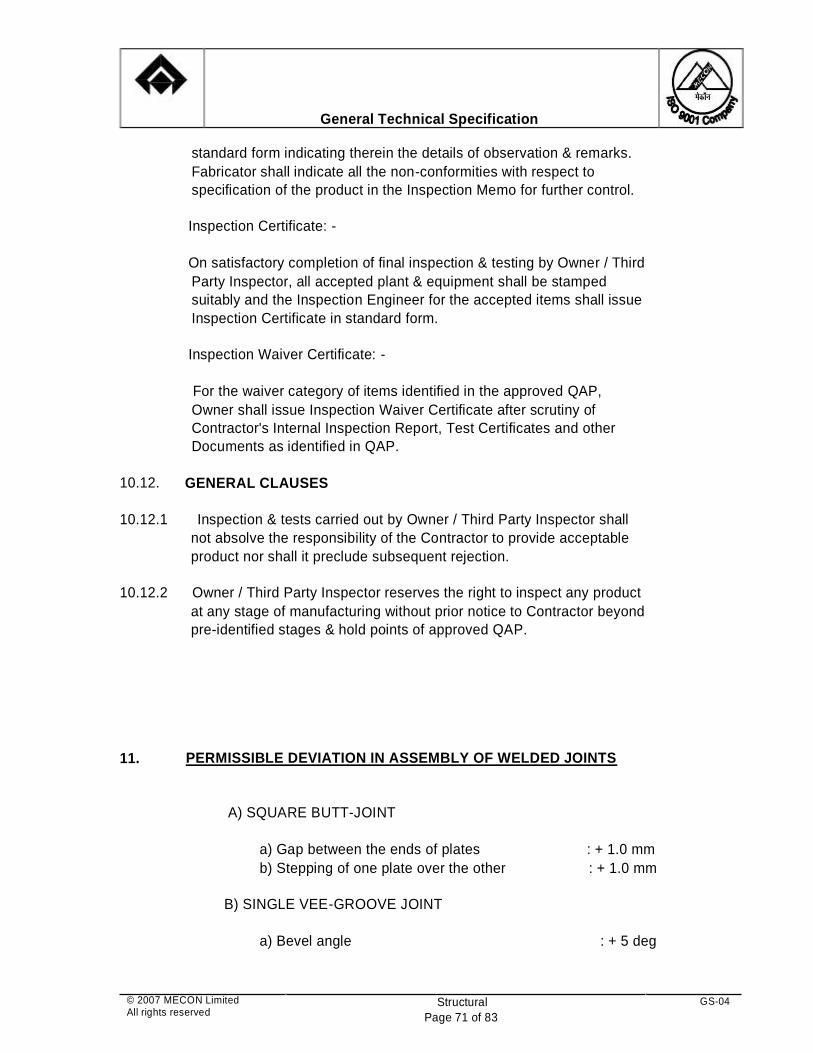
General Technical Specification
standard form indicating therein the details of observation & remarks.
Fabricator shall indicate all the non-conformities with respect to
specification of the product in the Inspection Memo for further control.
Inspection Certificate: -
On satisfactory completion of final inspection & testing by Owner / Third
Party Inspector, all accepted plant & equipment shall be stamped
suitably and the Inspection Engineer for the accepted items shall issue
Inspection Certificate in standard form.
Inspection Waiver Certificate: -
For the waiver category of items identified in the approved QAP,
Owner shall issue Inspection Waiver Certificate after scrutiny of
Contractor's Internal Inspection Report, Test Certificates and other
Documents as identified in QAP.
10.12.
10.12.1
10.12.2
11.
GENERAL CLAUSES
Inspection & tests carried out by Owner / Third Party Inspector shall
not absolve the responsibility of the Contractor to provide acceptable
product nor shall it preclude subsequent rejection. Owner / Third Party Inspector reserves the right to inspect any product
at any stage of manufacturing without prior notice to Contractor beyond
pre-identified stages & hold points of approved QAP. PERMISSIBLE DEVIATION IN ASSEMBLY OF WELDED JOINTS
A) SQUARE BUTT-JOINT
a) Gap between the ends of plates
b) Stepping of one plate over the other
B) SINGLE VEE-GROOVE JOINT
a) Bevel angle
: + 1.0 mm
: + 1.0 mm
: + 5 deg
© 2007 MECON Limited All rights reserved
Structural
Page 71 of 83
GS-04

General Technical Specification
b) Gap between two plates
c) Stepping of one plate over the other
d) Root thickness
C) LAP JOINT
a) Over lap
b) Gap between the surfaces
D) TEE FILLET JOINT
a) Gap between the edge of the web and
the surface of the flange
E) DOUBLE VEE-GROOVE JOINT
: + 1.0 mm
: + 2.0 mm
: + 1.0 mm
: + 5.0 mm
: + 1.0 mm
: + 2.0 mm
a)
b)
c)
d)
Stepping of plate over one another
Deviation in value of root thickness
Deviation in bevel angle
Deviation in value of gap
: + 2.0 mm
: + 1.0 mm
: + 1.0 mm
: + 1.0 mm
12.
PERMISSIBLE DEVIATIONS IN FABRICATION & ERECTION
TABLE – 1
DUST CATCHER SHELL
Description
Tolerance in mm
© 2007 MECON Limited All rights reserved
Structural
Page 72 of 83
GS-04

DESCRIPTION DEVIATION IN mm
Ellipticity (max. difference
in diameters) of a course.
+ 0.002 of the
theoretical diameter
of the course.
Stepping of the edges of
plates in the vertical and
circular weld joint.
0.1 of shell thickness
but not more than 3
mm.
Local warping of shell
along
the generatrix and
periphery
as measured by gauge
over the
length of 1500 mm.
Not more than 15 mm.
Ellipticity (max.
difference between
diameters ) of the
cylindrical and
conical portions.
0.005 of the
theoretical diameter
of the cylinder and
conical portion.
General Technical Specification
TABLE – 2
BLAST FURNACE SHELL
© 2007 MECON Limited All rights reserved
Structural
Page 73 of 83
GS-04

STRUCTURE NORMS FOR CONTROLLING AS A % OF
TOTAL LENGTH OF WELDING ( NOT
LESS THAN ) FOR
PLACES TO BE
SUBJECTED TO
RADIOGRAPHIC
TESTING
COMPULSORILY
ULTR-
SONIC
TESTING
RADIOGRAPHIC
TESTING
MANUAL &
SEMI-
AUTOMATIC
AUTOMATIC
BF Shell 100 3 2.0
Portions of the
welded joint found
defective by
ultrasonic testing
Stoves, hot
blast main &
bustle main
100 10 1.5 Portions of the
welded joint found
defective by
ultrasonic testing and
crossing of welded
joint
General Technical Specification
Caving in or bulging of
joints
measured by gauge over
a length of 200 mm.
5
Note : H - height measured from the base of the point of alignment.
TABLE – 3
COVERAGE OF NDT FOR WELDS
© 2007 MECON Limited
All rights reserved
Structural
Page 74 of 83
GS-04

Dust catcher,
Junction &
places of
variable cross
sections by
the following
norms
without
ultrasonic
testing
with
ultrasonic
testing
--
-
100
3
1
1.5
0.5
Crossing of welded
joint
Portions of the
welded joints found
defective by
ultrasonic welding
Portions of
gas pipelines
from BF to
DC & DC to
GCP
-- 1 0.5
Portions of the
welded joints found
defective by
ultrasonic testing
General Technical Specification
TABLE – 4
ERECTION TOLERANCES
© 2007 MECON Limited All rights reserved
Structural
Page 75 of 83
GS-04

DESCRIPTION TOLERANCE
(mm)
COLUMNS
Deviation of column axes at foundation top level
with respect to true axes
In longitudinal direction
In lateral direction
5
5
Deviation in the level bearing surface of
columns at foundation top level with respect to
true level .
5
Out-of-plumbness (verticality of column axis
from true vertical axis, as measured at column
top :
For columns without any special requirements
Up to and including 30 M height
Over 30 M height
For columns with special requirement like cranes
or such similar requirements.
Upt o and including 30 M height
Over 30 M height
H/1000 or
25 mm
whichever is
less.
H/1200 or
35 mm max.
H/1000 or
20 mm
whichever is
less.
H/1500 or
25 mm max.
Deviations in straightness in longitudinal and
transverse plans of columns at any point along
the height.
H/1000 or
10 mm
whichever is
less.
General Technical Specification
© 2007 MECON Limited
All rights reserved
Structural
Page 76 of 83
GS-04

DESCRIPTION TOLERANCES (mm)
TRUSSES
Shift, at the centre of span of top chord member
with respect to the vertical plan passing through
the centre of bottom chord.
1/250 of height of
truss at centre of span
or
15 mm whichever is
less.
Lateral shift of top chord of truss at the centre of
span from the vertical plan passing through the
centre of supports of the truss.
1/1500 of height of
truss at centre of span
or
Difference in the erected position adjacent
pairs of columns along with cross width of
building prior to connecting trusses/beams with
respect to true distance.
5
Deviation in any bearing or seating level with
respect to true level.
5
Deviation in difference in bearing levels of a
member on adjacent pair of columns both across
and along the building.
5
General Technical Specification
Note :
Tolerance specified under 3(a) & 3(b) should be read in conjunction with
4 & 5. 'H' above is the column height in mm.
contnd..
© 2007 MECON Limited All rights reserved
Structural
Page 77 of 83
GS-04

DESCRIPTION TOLERANCES (mm)
CRANE GIRDERS & RAILS
Shift in the centre line of crane rail with respect
to centre line of web of crane girder.
( web thickness + 2
)/2
Shift in plan of alignment of crane rail with
respect to true axis of crane rail at any point.
5
Deviations in crane track gauge with respect to
true crane gauge.
For track gauge up to and including 15 M.
For track gauge more than 15 M.
5
( 5 + 0.25 ( S-15 )
subject to a max. of
10 mm, where S in
10 mm whichever is
less.
Lateral shift in location of truss from its true
vertical position.
10 mm
Lateral shift in location of purlins from its true
positions.
5
Deviation in difference of bearing levels of
trusses or beam from the true difference.
L/1200 or 20 mm
whichever is less ( L =
span )
General Technical Specification
contnd..
© 2007 MECON Limited All rights reserved
Structural
Page 78 of 83
GS-04

meters is true track
gauge.
Deviations in crane rail level at any point from
true level.
10
Difference in levels between crane track rails (
across the bay ) at :
Support of crane girder
Mid span of crane girders
15
20
Relative shift of crane rail surfaces at a joint in
plan and elevations.
2 mm subject to
grinding of surfaces
for smooth transitions.
Relative shift in location of crane stops ( end
buggers ) along the crane track gauge.
1/1000 of track gauge
S in mm subject to
max. of 20 mm
CHIMNEYS & TOWERS
Out of plumbness ( vertically from the true
vertical axis ).
BUNKERS
1/1000 of the height of
chimney or tower in
mm.
Deviation in length of bunker from the true
length.
1/1000 of
length in mm
Deviation in width of bunker from the true width. 1/1000 of
width in mm
Deviation in height of bunker from the true
height.
1/1000 of
height in mm
General Technical Specification
© 2007 MECON Limited
All rights reserved
Structural
Page 79 of 83
GS-04

BF SHELL
Ellipticity ( the maximum difference in diameter
in diameter ) of courses .
0.002 of the
theoretical
diameter of
the courses.
STOVE SHELL
The dome centre shift with respect to the
bottom centre.
20
Ellipticity 0.002 of the
nominal
diameter
TOP STRUCTURES
Shift of frame centre from the designed position. 20 mm
Non horizontality of girders 3 mm per 1 m of
girder length.
DOWN COMERS
Erection and sag of down comers 0.0015 L but not more
than 80 mm. ( L is the
length of pipeline )
GAS PIPELINE SUPPORTS
General Technical Specification
© 2007 MECON Limited
All rights reserved
Structural
Page 80 of 83
GS-04

GAS & AIR
Distortion of flange /surfaces (except for the
furnace top one ) with respect to the branch
pipe/ pipe socket axis.
2 mm per 1 m of
flange diameter.
DUST CATCHER
Ellipticity 0.003 of the nominal
diameter of the
course.
BUSTLE PIPE
The deviations of the bottom level ( of the shell )
of the ring pipe ( measured along the axis of air
tuyere ) from the designed one.
10 mm
Ellipticity 0.003 of the
theoretical diameter.
Deviations of support axes from the vertical
plane.
0.002 h, but not more
than 20 mm, h is the
height of the support.
General Technical Specification
© 2007 MECON Limited
All rights reserved
Structural
Page 81 of 83
GS-04

General Technical Specification
Note :
The tolerances given at Sections 11 and 12 above, are meant as general
guidelines , mainly for technological structures , and for those not
covered in IS Codes.
Tolerances for fabrication and erection in general, shall be as per
stipulations of IS : 7215-1974 , and IS : 12843 -1989.
In case of a conflict between the guidelines given in IS Codes and this
Specification, those specified herein shall prevail.
ANNEXURE-A
Permissible deviations in pitch and gauge of holes for bolts of normal
accuracy ( high strength bolts included )
Hole diameter Permissible
Description (mm) deviations
In spacing
(mm)
1 2 3
Permissible deviations
in each group of holes
Carbon Low Alloyed
Steel Steel
4 5
a) Deviation Upto 17.0
in the hole Above 17.0
diameter
b) Ovality Upto 17.0;
(difference Above 17.0;
between the
biggest and
the smallest
diameter)
c) Curves, __
exceeding
1mm and
+1
+1.5
+1
+1.5
__
No limits
No limits
Not perm-
issible
© 2007 MECON Limited All rights reserved
Structural
Page 82 of 83
GS-04

General Technical Specification
cracks on
the hole
edges
d) (i) Non-coin- --
cidence of
holes in
separate
details of
the assem-
bled unit,
upto 1mm
(ii) Above 1 mm --
upto 1.5 mm
--
--
Upto 50%
Upto 10%
Upto 50%
Upto 10%
e) Slope of axis
--
Upto 30%
of the
thickness
of unit
No
Limits
No
Limits
© 2007 MECON Limited All rights reserved
Structural
Page 83 of 83
GS-04

PAINTING
(CHAPTER-09)

STEEL AUTHORITY OF INDIA LIMITED
BHILAI STEEL PLANT
GENERAL SPECIFICATION FOR
PAINTING (GS – 09)
MECON LIMITED RANCHI - 834002
No. MEC/S/1901/11/38/0/00/00/F1889/R2 JULY, 2007

��������������������
�������������� ���������������
�����������������
General Technical Specification
© 2007 MECON Limited All rights reserved
Painting Page 1 of 1
GS-09
CONTENTS Sl. No. Description Page No.
01 GENERAL 1
02 SURFACE PREPARATION 1
03 PAINT APPLICATION 3
04 PAINTING SCHEMES 6
05 GUARANTEE 7
ANNEXURE-01 – SURFACE PREPARATION GRADE 8
ANNEXURE-02 – PAINT MATERIALS 9
ANNEXURE-03 – PAINTING SCHEME 15
ANNEXURE-04 – COLOUR CODE 18

�����
�
�������������� ���������� �����
�����������������
General Technical Specification
© 2007 MECON Limited All rights reserved
Painting Page 1 of 19
GS-09
01 GENERAL 01.01 This spec i f ica t ion covers the mater ia ls , too ls , fac i l i t ies and qua l i t y
requ irement for sur face preparat ion and pa int ing of s teel s t ruc tures , equipment , p ip ing, ducts , chutes , wood work etc .
01.02 This is only a genera l gu ide l ine of the pa int ing scheme to be fo l lowed by
the Tenderer . However , in case a spec i f ic paint ing procedure is s t ipu la ted in any tender ing spec i f ica t ion , then th is genera l gu idel ine sha l l be superceded. Any spec ia l case which may ar ise f rom t ime to t ime sha l l be deal t w i th ind iv idual l y on the mer i t o f each case
01.03 The term “paint ing” re fer red here in covers rus t prevent ive, fungus/ insects
prevent ive and decorat ive coat ing a long wi th sur face protec t ion of the fo l lowing area but not l im i ted to the areas ind icated below.
i ) St ruc tura l s tee l works i i ) Mechanical equ ipment i i i ) E lec t r ica l equipment iv) Ins t rumentat ion and contro l equ ipment . v) Pipe work v i ) Oxygen p lant , e tc .
01.04 Sur faces made of asbestos , a lum inum, brass, bronze, ga lvan ized s teel ,
s ta in less s teel , cas t i ron and other cor ros ion res is tant a l loys and rubber /s yn thet ic po lymer / f iber re inforcement p las t ic and bur ied p ipe work are no t required to be pa in ted un less spec i f ied except for aes thet ic purposes or for ident i f icat ion bands , wherever re levant .
01.05 The complete pa in t sys tem for any i tem inc ludes the fo l lowing bas ic
ac t iv i t ies : i ) Proper sur face preparat ion i i ) Appl icat ion of pr imer coats i i i ) Appl icat ion of in termediate coats iv) Appl icat ion of f in ished coats Al l the above coats sha l l be of qua l i t y paint products and of approved make. The scope of work shal l a lso inc lude supp ly of a l l pa int mater ia ls as per spec i f icat ion desc r ibed here in.
01.06 I f the contrac tor des ires to adopt a l terna t ive pa int s ys tem for any spec i f ic i tem for an improvement or equ iva lent to the s ys tem spec i f ied here- in or as per recommendat ions of paint manufacturer , may do so subjec t to purchaser ’s approva l in advance.
02 SURFACE PREPARATION 02.01 Sur face preparat ion required for pa int appl ica t ion , sha l l be such as to
c lean the sur face thorough ly of any mater ia l wh ich wi l l be conduc ive to premature fa i lure of the paint subs trates .

�����
�
�������������� ���������� �����
�����������������
General Technical Specification
© 2007 MECON Limited All rights reserved
Painting Page 2 of 19
GS-09
02.02 Al l sur faces sha l l be c leaned of loose substances, and fore ign mater ia ls , such as d i r t , rus t , scale, o i l , grease, weld ing f lux , e tc . in order that the pr ime coat is r ig id l y anchored to the v i rg in meta l sur face. The sur face prepara t ion sha l l conf i rm to p ic tor ia l representat ion of sur face qua l i t y grade of Swed ish Standards Ins t i tu t ion SIS – 055900 or equ iva lent s tandards such as SSPC – VIS – 1 .67 or DIN 55928(Par t 4) or BS 4232 or IS 1477 – 1971 (Par t I )
02.03 The acceptab le sur face prepara t ion qual i t y / grade are descr ibed under
each paint sys tem. The procedures inc lude so lvent c lean ing, hand too l c lean ing, power too l c leaning , b las t c leaning , wood sur face c lean ing, f lame c lean ing and p ick l ing. This wi l l ensure sur face qua l i t y as requ ired by the spec i f ic pr imer paint . For ready reference sur face preparat ion qual i t y grade to be adopted in respect of SIS 055900 and DIN 55928 (par t -4) is g iven in Annexure-01.
02.03 .01 Solvent Cleaning
The sur face sha l l be c leaned by wip ing, immers ion , spraying or vapour contac t ing of a su i tab le so lvent or washing wi th an emuls ion or a lka l ine solut ion to remove o i l , grease, d i r t , o ld pa int , e tc . Solvent c lean ing sha l l not remove rus t , scales , m i l l sca les or we ld f lux . Therefore, before appl ica t ion of pa int , so lvent c lean ing shal l be fo l lowed by other c lean ing procedures as s ta ted in subsequent c lauses.
02.03 .02 Hand Tool Cleaning
The sur face sha l l be c leaned manua l ly by v igorous wire brush ing as per grade St-2 qual i t y of Swed ish Standard Ins t i tu t ion SIS 055900 and DIN 555928. Th is method ef fec t ive l y removes loose ly adherent mater ia ls , but wou ld not af fec t res idues of rus t or m i l l scales tha t are in tac t are f i rm ly adherent . F ina l ly the sur face is to be c leaned wi th a vacuum c leaner or wi th c lean compressed a i r or wi th c lean brush. Af ter preparat ion the sur face sha l l have a fa int meta l l ic sh ine. The appearance shal l cor respond to the pr in ts des ignated St – 2.
02.03 .03 Power Tool C leaning The sur face shal l be c leaned by e lec t r ic or pneumat ic too ls , such as brushes, sand ing machines, d isc abras ive gr inder , ro tar y d isc scaler etc . to St – 3 qua l i t y. The too ls sha l l be used carefu l l y to prevent excess ive roughen ing of sur face and format ion of r idges and burrs . This method wi l l remove loose ly adherent mater ia ls bu t wou ld not af fec t res idues of rus t or m i l l sca les that are f i rm ly adherent and in tac t .
02.03 .04 Blast C leaning
The sur face shal l be c leaned by impingement of abras ive mater ia ls , such as graded sand at h igh ve loc i t y c reated by c lean and dr y compressed a i r b las t as per the grade accord ing to Swedish Standard Ins t i tu t ion SIS 055900 .This method wi l l remove loose ly adherent mater ia ls as we l l as adherent sca les and m i l l sca les . Pr ior to appl ica t ion of b las t , heavy depos i t o f o i l and grease are removed by solvent c lean ing excess ive
�����
�
�������������� ���������� �����
�����������������
General Technical Specification
© 2007 MECON Limited All rights reserved
Painting Page 3 of 19
GS-09
sur face scales are removed by hand too ls or power too l c leaning . The ex tent of removal o f adherent scales is var ied, depend ing on the appl ica t ion and are def ined by the sur face qual i t y grades Sa1, Sa2, Sa2.5 and Sa3 in the order of increas ing c lean l iness. The b las t c lean ing is not recommended for sheet meta l work .
02.03 .05 Flame Cleaning The sur face is c leaned by rap id heat ing by means of ox yacetylene f lame
to loosen the adherent sca les , fo l lowed immediate l y by wire brush ing. This method wi l l remove loose ly adherent mater ia ls as we l l as most of the adherent sca les and m i l l scales . In order to m in im ize or prevent d is tor t ion f lame cut t ing shal l no t be used on members having th ickness of 6 mm and lower .
02.03 .06 Pickl ing In th is method the sur face is c leaned of m i l l scales , rus t or rus t scales by
chemical reac t ion or e lec t ro l ys is or both.
03. PAINT APPLICAT ION 03.01 Paints 03.01 .01 Pa in t sha l l be appl ied in accordance wi th pa in t manufacturer ’s
recommendat ions. The work sha l l genera l l y fo l low IS 1477 – 1971 (Par t I I ) for jobs car r ied ou t in Ind ia and SSPC-PA-1 or D IN 55928 or equ iva lent for jobs car r ied ou t ou ts ide India.
03.01 .02 Genera l compat ib i l i t y be tween pr imer and f in ish ing pa in ts sha l l be
es tabl ished by the pa int manufacturer supp ly ing the paints . 03.01 .03 In the event of conf l i c t be tween th is genera l procedure on paint ing and
the pa in t manufacturer ’s spec i f icat ion, the same shal l be immediate l y brought to the no t ice of the Purchaser . Genera l l y in cases of such conf l ic ts , manufacturer ’s spec i f icat ions/ recommendat ions sha l l preva i l .
03.01 .04 Before buying the pa in t in bu lk , i t is recommended to obta in sample of
pa in t and es tab l ish “Contro l Area of Paint ing” . On Contro l Area , sur face prepara t ion and paint ing sha l l be car r ied ou t .
03.01 .05 I f requ ired, samples of pa int sha l l be tes ted in laborator ies to es tabl ish
qual i t y of pa int wi th respec t to : ( i ) V iscos i t y ( i i ) Adhes ion/Bond of pa int in s tee l sur faces ( i i i ) Adhes ion/S imulated sal t spray tes t . ( iv) Chemica l analys is (percentage of so l ids by we ight) (v) Normal wear res is tance as encountered dur ing hand l ing & erec t ion. (v i ) Res is tance aga ins t exposure to ac id fumes, etc . 03.01 .06 W hole quant i t y of pa int for a par t icu lar sys tem of paint sha l l be obta ined
f rom the same manufacturer .

�����
�
�������������� ���������� �����
�����������������
General Technical Specification
© 2007 MECON Limited All rights reserved
Painting Page 4 of 19
GS-09
03.01 .07 The main Contrac tor sha l l be respons ib le for supp ly of pa ints and th is
respons ib i l i t y sha l l no t be passed on to the sub-contrac tor . 03.01 .08 The paint ing mater ia l as de l ivered to the Contrac tor , must be in the
manufacturer ’s or ig inal conta iner bear ing thereon manufacturer ’s name brand and descr ip t ion . Pa int /Pa int ing mater ia l in conta iners wi thout labels or wi th i l leg ib le labe ls shal l be re jec ted, removed f rom the area and shal l not be used.
03.01 .09 Thinners wherever used sha l l be those recommended by the pa in t
manufacturers and sha l l be obta ined in conta iners wi th manufacturer ’s name and brand name of th inner leg ib l y pr in ted, fa i l ing wh ich the th inner is l iab le to be re jec ted and shal l no t be used.
03.01 .10 Al l pa int conta iners sha l l be c lear l y labe led to show the paint
iden t i f icat ion, da te o f manufacture, ba tch number , spec ia l ins t ruc t ion, she l f l i fe e tc . The conta iner shal l be opened on ly at the t ime of use.
03.01 .11 Al l pa ints shal l be s tored in accordance wi th the requ irements of la id
down procedure by the pa int manufacturer . 03.01 .12 Al l ingred ients in a paint con ta iner sha l l be thorough ly m ixed to break -up
lumps and d isperse p igments before use and dur ing app l icat ion to mainta in homogene i t y.
03.01 .13 The proposed make, qua l i t y and shade of the paint shal l have the approva l o f the c l ien t .
03.01 .14 The colour code of the f in ish ing pa in t to be fo l lowed sha l l be in t imated to
the successfu l Tenderer af ter f ina l isa i ton of order . The undercoat sha l l have d i f ferent t in t to d is t ingu ish the same f rom the f in ish ing coat .
03.01 .15 The Contrac tor sha l l furn ish pa int manufac turer ’s tes t repor t or technica l
data sheet per ta in ing to the pa int se lec ted . The data sheet sha l l ind icate among other th ings the re levant s tandards , i f any, compos i t ion in we ight percent of p igments , veh ic les , add i t ives , dry ing t ime, v iscos i t y, spread ing rate , f lash po int , method of app l icat ion, qual i t y of sur face preparat ion requ ired, cor ros ion res is tance proper t ies and co lour shades ava i lab le .
03.01 .16 For deta i ls of pa int mater ia ls refer Annexure - 02 03.02 General 03.02 .01 Each coat of pa in t sha l l be cont inuous, f ree of pores and of even f i lm
th ickness wi thout th in spots . 03.02 .02 Each coat of pa int shal l be suf f ic ient l y dr y before app l icat ion of next coa t . 03.02 .03 Pa in t shal l be app l ied at manufacturer ’s recommended ra tes . The number
of coats sha l l be such that the m in imum dry f i lm th ickness spec i f ied is ach ieved. The dr y f i lm th ickness of painted sur faces shal l be checked wi th ELCOMETER of measur ing gauges to ensure app l icat ion of spec i f ied DFT.

�����
�
�������������� ���������� �����
�����������������
General Technical Specification
© 2007 MECON Limited All rights reserved
Painting Page 5 of 19
GS-09
03.02 .04 Z inc r ich pr imer pain ts wh ich have been exposed severa l months before f in ish ing coat is app l ied sha l l be washed down thorough ly to remove solub le z inc sa l t depos i ts .
03.02 .05 The machine f in ished sur faces sha l l be coated wi th wh i te lead and ta l low
before sh ipment or be fore being put ou t in to the open a i r . 03.02 .06 Areas wh ich become inaccess ib le af ter assemble sha l l be painted before
assembly (af ter obta in ing paint ing c learance f rom the inspect ing author i t y) a f ter requ is i te sur face c lean ing as spec i f ied .
03.02 .07 Pa in t sha l l no t be appl ied when the ambient tempera ture is 5 deg C and
be low or 45 deg C and above. Also pa int shal l not be app l ied in ra in , wind, fog or at re lat ive humidi ty of 80 % and above un less the manufacturer ’s recommendat ions perm it . Appl icat ions of pa in t sha l l be on ly be spraying or brush ing as per IS 486 – 1983 and IS 487 – 1985.
03.02 .08 Pr imer pa int shal l be appl ied no t la ter than 2 – 3 hours af ter preparat ion
of sur face, un less spec i f ied o therwise. 03.02 .09 Edges, corners , c rev ices, depress ions, jo in ts and we lds sha l l rece ive
spec ia l a t tent ion to ensure that they rece ive pa int ing coats of the requ ired th ickness.
03.02 .10 Sur faces wh ich cannot be painted bu t requ i re pro tec t ion sha l l be g iven a
coat of rus t inh ib i t i ve grease accord ing to IS 958 – 1975 or so lvent depos i ted compound accord ing to IS 1153 – 1975 or IS 1674 – 1960.
03.02 .11 Sur faces in contac t dur ing shop assembly sha l l not be pa inted. Sur faces
wh ich wi l l be inaccess ib le af ter assembly shal l rece ive m in imum two coats of spec i f ied pr imer .
03.02 .12 Sur faces to be in contac t wi th wood, br ick or other masonry shal l be g iven
one shop-coat of the spec i f ied pr imer . 03.03 Site/Field Paint ing 03.03 .01 W herever shop pr imer pa int ing is scratched, abraded or damaged, the
sur face sha l l be thorough ly c leaned us ing emery paper and power dr iven wire brush wherever warran ted, and touched up wi th cor respond ing pr imer . Touch ing up pa in t sha l l be matched and b lended to e l im ina te consp icuous marks .
03.03 .02 I f more than 50% of the pa inted sur face o f an i tem requires repa ir , the
ent i re i tem sha l l be mechanical l y c leaned and new pr imer coats sha l l be appl ied fo l lowed by in termediate and f in ish ing coats as per pa in t ing spec i f icat ion.
03.03 .03 Al l f ie ld we lded areas on shop pa inted i tems shal l be mechan ica l l y
c leaned ( inc lud ing the we ld area proper , ad jacent areas contaminated by we ld spat ter or fumes and areas where ex is t ing pr imer paint is burnt ) .

�����
�
�������������� ���������� �����
�����������������
General Technical Specification
© 2007 MECON Limited All rights reserved
Painting Page 6 of 19
GS-09
Subsequent l y, new pr imer and f in ish ing coats of pa int sha l l be appl ied as per pa int ing spec i f icat ion.
03.03 .04 The f i rs t coat of f in ish paint a t s i te sha l l be appl ied preferab le wi th in three
months of the shop pa in t . 03.04 Structural
03.04 .01 Al l fabr icated s teel s t ruc ture, fabr icated s tee l p ipes, etc . sha l l have a
m in imum of two coats of pr imer paint before d ispatch to s i te . 03.04 .02 Par ts of s tee l s t ruc tures embedded in concrete sha l l be g iven a protec t ive
coat of Por t land cement s lur ry immediate l y af ter fabr icat ion and af ter sur faces of th is par t i s thorough ly c leaned f rom grease, rus t , m i l l sca les , etc . No paint sha l l be appl ied on th is par t .
03.04 .03 Al l s t ruc tures sha l l rece ive appropr ia te number of pr imer and f in ish ing
coats in order to achieve overa l l DFT as per des ign drawings/spec i f icat ion .
03.05 Hot Surfaces 03.05 .01 Tota l DFT for heat res is tant pa in ts shou ld not exceed 100 – 120 m icrons,
otherwise f lak ing occurs (as per pa in t manufacturer ’s recommendat ions) . 03.05 .02 Heat res is tan t pa ints shou ld be app l ied by brush. 03.05 .03 Pr imer coat shou ld not be app l ied on the sur faces hav ing tempera ture
cond i t ion more that 120 deg C. 04 PAINTING SCHEMES
For a complete paint ing scheme of any i tem being pr in ted, a l l t ypes of pa in ts are to be procured f rom the same manufacturer as approved by the purchaser .
04.01 Legend SP - Sur face preparat ion qua l i t y as per SIS s tandard 2P1 - Two (2) coats of Pr imer paint t ype P1
1I1 - One (1) coats of In termediate pa in t t ype I1 2F1 - Two (2) coats of F in ish pa int t ype F1 DFT - Dry F i lm Thickness in m icrons developed CRT- Clean and Retouch Type of pa int products l ike P1 to P9, I1 to I4 and F1 to F10 have been spec i f ied under Annexure-02.
04.02 The pa in t ing scheme to be fo l lowed fo r var ious s t ruc ture/equ ipment exposed to d i f ferent condi t ion is br ie f ly g iven in Annexure-03 for guidance to the tenderer .

�����
�
�������������� ���������� �����
�����������������
General Technical Specification
© 2007 MECON Limited All rights reserved
Painting Page 7 of 19
GS-09
04.03 The colour code for d i f feren t app l icat ions are ind icated in Annexure-04 . W herever co lour codes are not spec i f ied, the same is to be mutual l y agreed between the Purchaser and Contrac tor .
05. GUARANTEE 05.01 The Contrac tor shal l guarantee tha t the phys ica l and chemical p roper t ies
of the pa int mater ia ls conform wi th the spec i f icat ion of paint products . 05.02 The Contrac tor shal l submit in terna l tes t repor ts f rom paint manufacturers
regard ing the qual i t y of pa int whenever asked by the Purchaser /Consu l tan t .
05.03 Guarantee per iod sha l l commence f rom the date of complet ion of f in ish ing
coat of pa int . The guarantee per iod wi l l be ind icated depending on the type of sur face prepara t ion and s ys tem of paint ing. To fu l f i l l th is ob l iga t ions the Contrac tor may ob ta in f rom the pa in t ing manufacturer , guarantee for the per formance of pa int /pa in ted sur faces.
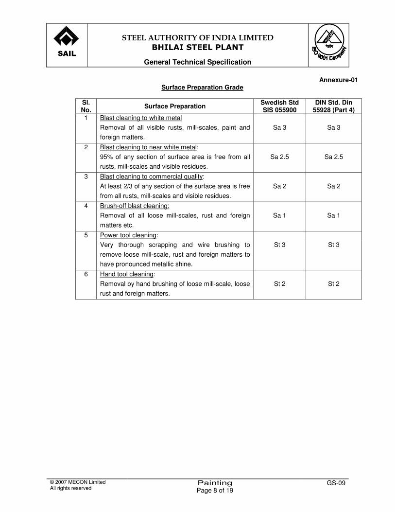
�����
�
�������������� ���������� �����
�����������������
General Technical Specification
© 2007 MECON Limited All rights reserved
Painting Page 8 of 19
GS-09
Annexure-01 Surface Preparation Grade
Sl. No. Surface Preparation Swedish Std
SIS 055900 DIN Std. Din
55928 (Part 4) 1 Blast cleaning to white metal Removal of all visible rusts, mill-scales, paint and
foreign matters. Sa 3 Sa 3
2 Blast cleaning to near white metal: 95% of any section of surface area is free from all
rusts, mill-scales and visible residues. Sa 2.5 Sa 2.5
3 Blast cleaning to commercial quality: At least 2/3 of any section of the surface area is free
from all rusts, mill-scales and visible residues. Sa 2 Sa 2
4 Brush-off blast cleaning: Removal of all loose mill-scales, rust and foreign
matters etc. Sa 1 Sa 1
5 Power tool cleaning: Very thorough scrapping and wire brushing to
remove loose mill-scale, rust and foreign matters to have pronounced metallic shine.
St 3 St 3
6 Hand tool cleaning: Removal by hand brushing of loose mill-scale, loose
rust and foreign matters. St 2 St 2

�����
�
�������������� ���������� �����
�����������������
General Technical Specification
© 2007 MECON Limited All rights reserved
Painting Page 9 of 19
GS-09
Annexure - 02 PAINT M ATERIALS
01. PRIMER PAINTS (P) Pr imer paint products sha l l be app l ied on ly on dr y and c lean sur faces. 01.01 Primer Paint – P1 (Phenol ic – Alkyd Based) A s ing le pack a i r dry ing pheno l ic modi f ied a lk yd compos i t ion wi th z inc
phosphate as a pr imer pa int conform ing genera l l y to IS : 2074.
Air drying time - About 60 minutes (touch dry)
- Overnight (hard dry)
Dry film thickness (DFT)/Coat - 40 microns (min)
Temperature resistance - Upto 1000C dry heat
01.02 Primer Paint – P2 (Chlororubber Based) A s ing le pack a i r drying h igh bu i ld ch lor ina ted rubber based z inc
phosphate pr imer .
Percent chlororubber - 20 to 22 (% Chlorine above 65% in chlororubber)
Air drying time - About 15 minutes (touch dry) - Overnight (hard dry)
DFT/ Coat - 50 microns (min)
Temperature resistance - Up to 650 C dry heat
01.03 Primer Paint – P3 (PVC Copolymer Alkyd Based)
Polyvinyl chloride (PVC) - Alkyd zinc phosphate – redoxide based primer
Ratio : PVC copolymer + alkyd resin (1:1)
Pigments : Zinc phosphate & Fillers
Air drying time - 24 hours
DFT/Coat - 80 microns
Temperature resistance - Upto 800C dry heat

�����
�
�������������� ���������� �����
�����������������
General Technical Specification
© 2007 MECON Limited All rights reserved
Painting Page 10 of 19
GS-09
01.04 Primer Paint – P4 (Epoxy Based) A two pack a i r dr ying Epoxy po lyamide res in based red ox ide-z inc
phosphate pr imer .
Epoxy content (% wt.) - 15 to 18
Air drying time - -
About 30 minutes (touch dry) overnight (hard dry)
DFT/Coat - 30 microns (min)
Temperature resistance - Upto 1200C dry heat
01.05 Primer Paint – P5 (Epoxy Based) A two pack a i r dr ying Epoxy po lyamide wi th zinc dust of a t leas t 92% zinc
dust on the dr y f i lm
Epoxy content (% wt.) - 8 to 10
Air drying time -
Less than 10 minutes (touch dry) Less than 2 hours (hard dry)
DFT/Coat - 40 microns (min)
Temperature resistance - Upto 3000C dry heat
01.06 Primer Paint – P6 (Poly – Vinyl Butyral Resin Based) A two pack a i r dr ying po lyv inyl butyra l res in based wash pr imer wi th rus t
inh ib i t ive p igments .
Air drying time - -
5 to 7 minutes (touch dry) 2 hours (hard dry)
DFT/Coat - 8 microns
Temperature resistance - Upto 650C dry heat
Application for - Galvanised iron, aluminium, light alloys etc. on which the adhesion of conventional paints are poor.
01.07 Primer Paint – P7 (Ethyl Zinc Silicate, EZS Based).
A two pack heavy du ty z inc dust r ich s i l icate pr imer wh ich protec ts the sur face wi th jus t a s ingle coat .
Tota l so l ids (3 wt) - 84 +/- 2 Dens ity ( g / cc ) - 3.07 +/- 0.05

�����
�
�������������� ���������� �����
�����������������
General Technical Specification
© 2007 MECON Limited All rights reserved
Painting Page 11 of 19
GS-09
A ir drying t ime - To top coat 16 hours DFT / coat - 60 microns Temperature res istance - Upto 450 deg C dry heat
01.08 Primer Paint – P8 (High Bui ld Coal Tar Epoxy) A two pack cold cured H.B. epoxy coal tar coat ing – no pr imer is required. Mix ing rat io - Base: Hardener (4:1by vol .) A ir drying t ime - 48 hours (hard dry) Ful l cure 7 days DFT / Coat - 100 microns 01.09 Wood Varnish-P9
Treated o i l based pr imer p igmented wi th su itab le p igments : A ir drying t ime - 16 hours for appl icat ion of top coat . Coverage - 10 to 14 sq. m/l i t re
02. INTERMEDIATE PAINTS ( I)
These paints shal l be appl ied over pr imer coats as an in termediate layer to provide weather proof seal of pr imer coats.
02.01 Intermediate Paint - I I ( Phenol ic alkyd based)
A s ingle pack high bui ld phenol ic based paint with micaceous i ron ox ide (M10) . A ir Drying T ime - 4 to 6hours ( touch dry) - 2 days (hard dry) DFT /Coat - 75 microns (min) Temperature res istance - Upto 100 deg C dry heat Compat ib le wi th - Pr imer P1
02.02 Intermediate Paint - I2 (Chlororubber based)
A s ingle pack a ir drying h igh bui ld ch loro based paint wi th MIO. Air Drying T ime - 15 minutes ( touch dry)
- 24 hours (hard dry) DFT/Coat - 70 microns (min)
Temperature res istance - Upto 65 deg C dry heat Compat ib le wi th - Pr imer P2,P3 & P4
02.03 Intermediate Paint - I3 (PVC – Alkyd Based)
PVC Coploymer - Res in 1 : 1 Pigments - Micaceous iron ox ide (MIO) DFT/Coat - 80 microns (min)

�����
�
�������������� ���������� �����
�����������������
General Technical Specification
© 2007 MECON Limited All rights reserved
Painting Page 12 of 19
GS-09
Temperature res istance - Upto 80 deg C dry heat Compat ib le wi th - Pr imer P2 & P3
02.04 Intermediate paint- I4
A two pack a ir drying h igh bui ld epoxy res in based paint wi th MIO. Air drying t ime - 6 to 8 hours ( touch dry) - 7 days ( fu l l cure) DFT / coat - 100 microns Temperature res istance - Up to 1800C dry heat Compat ib le wi th - Pr imer P4 & P5 03. FINISH PAINTS (F) F in ish paint cos ts shal l be app l ied over pr imer coats and in termedia te
coats af ter proper c lean ing and touch up of pr imed sur face. 03.01 Finish Paint – F1 A s ing le pack a i r dry ing h igh g loss pheno l ic a lk yd modi f ied synthe t ic
enamel paint su i tab ly p igmented.
Air drying time - -
3 to 4 hours (touch dry) 24 hours (hard dry)
DFT/Coat - 25 microns (min)
Temperature resistance - Upto 1000C dry heat
Compatible with - Primer P1 Intermediate I1
Colour
- Generally all shades
03.02 Finish Paint – F2 A s ing le pack a i r dr ying po lyure thane enamel of h igh g loss and hard f in ish
sui tab ly p igmented.
Air drying time - -
2 to 2 ½ hours (touch dry) 6 hours (hard dry)
DFT/Coat - 30 microns (min)
Temperature resistance - Upto 1000C dry heat
Compatible with - Primer P1 & P8 and Intermediate I1
Colour
- Generally all shades
�����
�
�������������� ���������� �����
�����������������
General Technical Specification
© 2007 MECON Limited All rights reserved
Painting Page 13 of 19
GS-09
03.03 Finish Paint – F3 A two pack a i r drying b i tum inous a lum inum pa in t .
Air drying time - -
1 to 2 hours (touch dry) 21 hours (hard dry)
DFT/Coat - 25 microns (min)
Temperature resistance - Upto 1000C dry heat
Compatible with - Primer P1 and Intermediate I1
Colour
- Bright metallic
03.04 Finish Paint – F4 A ready m ixed o i l -a lkyd based s yn thet ic enamel pa int o f h igh g loss and
hard wear ing proper t ies .
Air drying time -
6 to 8 hours
Coverage - 14 to 16 Sq. m /litre
Temperature resistance - Upto 600C dry heat
Compatible with - P8
Colour
- Generally all shades
03.05 Finish Paint – F5 A s ingle pack a i r dr ying p las t ic ized ch lororubber pa int su i tab ly p igmented.
Air drying time - -
30 minutes (touch dry) 24 hours (hard dry)
DFT/Coat - 35 microns (min)
Temperature resistance - Upto 650C dry heat
Compatible with - Primer P2 & P3, Intermediate I2 & I3
Colour
- Nearly all shades except few.

�����
�
�������������� ���������� �����
�����������������
General Technical Specification
© 2007 MECON Limited All rights reserved
Painting Page 14 of 19
GS-09
03.06 Finish Paint – F6 A PVC – Copo lymer a lk yd based enamel.
Density -
1.17 + 0.05
Total solids (1 wt)
- 55 + 2
DFT/Coat - 40 microns
Compatible with - P2 and P3 03.07 Finish Paint – F7 A two pack a i r drying epoxy polyamide enamel su i tab ly p igmented.
Air drying time - -
2 to 3 hours (touch dry) 7 days (full cure)
DFT/Coat - 40 microns (min)
Temperature resistance - Up to 1300C dry heat
Compatible with - Primer P4 & P5, Intermediate I4
Colour
- Generally all shades.
03.08 Finish Paint – F8 A s ingle pack syn thet ic rubber based a lum in ium pa in t .
Air drying time - -
2 hours (touch dry) 24 hours (hard dry)
DFT/Coat - 25 microns (min)
Temperature resistance - Upto 2000C dry heat
Compatible with - No Primer paint except primer P6 is applicable in case of non-ferrous substrate.
Colour
- Smooth aluminium.
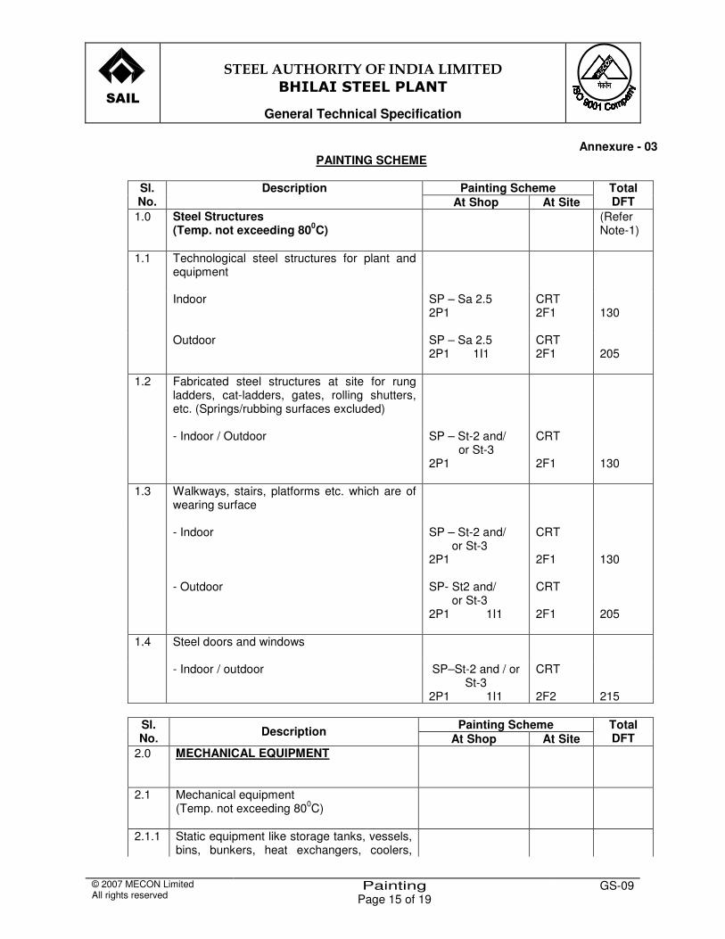
�����
�
�������������� ���������� �����
�����������������
General Technical Specification
© 2007 MECON Limited All rights reserved
Painting Page 15 of 19
GS-09
Annexure - 03 PAINTING SCHEME
Painting Scheme Sl.
No. Description
At Shop At Site Total DFT
1.0 Steel Structures (Temp. not exceeding 800C)
(Refer Note-1)
1.1 Technological steel structures for plant and equipment
Indoor
SP – Sa 2.5 2P1
CRT 2F1
130
Outdoor
SP – Sa 2.5 2P1 1I1
CRT 2F1
205
1.2 Fabricated steel structures at site for rung ladders, cat-ladders, gates, rolling shutters, etc. (Springs/rubbing surfaces excluded)
- Indoor / Outdoor
SP – St-2 and/ or St-3 2P1
CRT 2F1
130
1.3 Walkways, stairs, platforms etc. which are of wearing surface
- Indoor
SP – St-2 and/ or St-3 2P1
CRT 2F1
130
- Outdoor
SP- St2 and/ or St-3 2P1 1I1
CRT 2F1
205
1.4 Steel doors and windows
- Indoor / outdoor
SP–St-2 and / or St-3
2P1 1I1
CRT 2F2
215
Painting Scheme Sl.
No. Description At Shop At Site Total DFT
2.0 MECHANICAL EQUIPMENT
2.1 Mechanical equipment (Temp. not exceeding 800C)
2.1.1 Static equipment like storage tanks, vessels, bins, bunkers, heat exchangers, coolers,
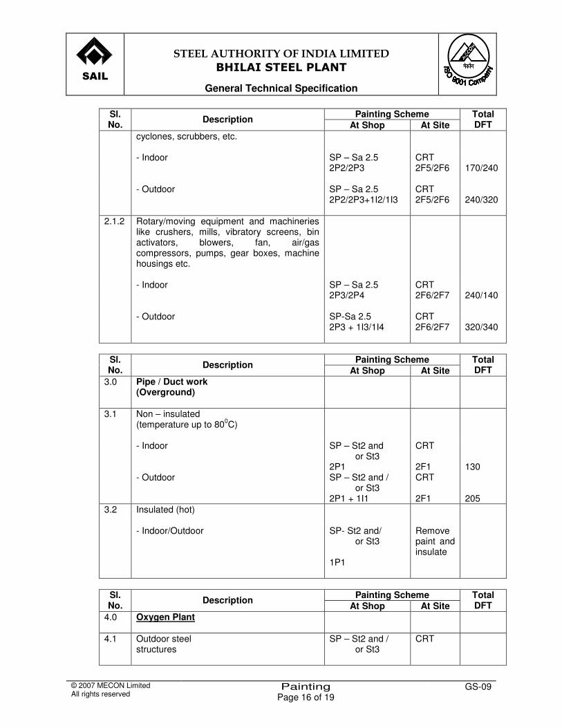
�����
�
�������������� ���������� �����
�����������������
General Technical Specification
© 2007 MECON Limited All rights reserved
Painting Page 16 of 19
GS-09
Painting Scheme Sl. No. Description At Shop At Site
Total DFT
cyclones, scrubbers, etc.
- Indoor
SP – Sa 2.5 2P2/2P3
CRT 2F5/2F6
170/240
- Outdoor
SP – Sa 2.5 2P2/2P3+1I2/1I3
CRT 2F5/2F6
240/320
2.1.2 Rotary/moving equipment and machineries like crushers, mills, vibratory screens, bin activators, blowers, fan, air/gas compressors, pumps, gear boxes, machine housings etc.
- Indoor
SP – Sa 2.5 2P3/2P4
CRT 2F6/2F7
240/140
- Outdoor SP-Sa 2.5 2P3 + 1I3/1I4
CRT 2F6/2F7
320/340
Painting Scheme Sl.
No. Description At Shop At Site Total DFT
3.0 Pipe / Duct work (Overground)
3.1 Non – insulated (temperature up to 800C)
- Indoor SP – St2 and or St3
2P1
CRT 2F1
130
- Outdoor SP – St2 and / or St3
2P1 + 1I1
CRT 2F1
205
3.2
Insulated (hot)
- Indoor/Outdoor
SP- St2 and/ or St3
1P1
Remove paint and insulate
Painting Scheme Sl.
No. Description At Shop At Site Total DFT
4.0 Oxygen Plant
4.1 Outdoor steel structures
SP – St2 and / or St3
CRT

�����
�
�������������� ���������� �����
�����������������
General Technical Specification
© 2007 MECON Limited All rights reserved
Painting Page 17 of 19
GS-09
Painting Scheme Sl. No. Description At Shop At Site
Total DFT
2P1 + 1I1 2F3 205 4.2 Rotary equipment like air compressors Sa 2.5
2P4 CRT 2F7
140
5.0 Others
5.1 Standard mobile equipment like chasis of trucks, dumpers, crawler cranes bulldozers, railway rakes, chasis of slag cars, ladle cars, etc.
As per manufacturer’s standards
5.2 Laboratory equipment like ovens, screens, magnetic stirrers, samplers, etc.
Stove enamelling CRT
110
5.3
Steel structures partly immersed in water
SP – Sa 2.5 2P8
CRT 200
Notes: - 1 . Pa in t ing scheme of a l l fabr ica ted s tee l s t ruc tures , fabr icated p ipe work , bu i ld ing
s t ruc ture, conveyor gal ler ies , p ipe t res t les etc . is ind ica ted in the Techn ica l Spec i f icat ion of s tee l s t ruc tures .
2 . Pr imer Pa in t Pr imer coat sha l l be sui tab le for in tended temperature app l icat ions as per
manufacturer ’s recommendat ion. The pr imer se lec t ion sha l l be genera l l y in l ine wi th the spec i f icat ion la id down in Annexure-02.
3 . F in ish Pa int In case of A lum in ium c ladd ing f ina l pa in t ing wi l l not be required .
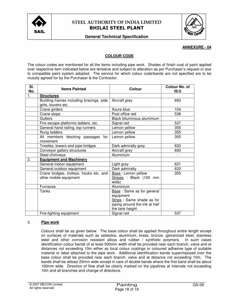
�����
�
�������������� ���������� �����
�����������������
General Technical Specification
© 2007 MECON Limited All rights reserved
Painting Page 18 of 19
GS-09
ANNEXURE - 04
COLOUR CODE The colour codes are mentioned for all the items including pipe work. Shades of finish coat of paint applied over respective item indicated below are tentative and subject to alteration as per Purchaser’s request or due to compatible paint system adopted. The service for which colour code/bands are not specified are to be mutully agreed for by the Purchaser & the Contractor. Sl. No. Items Painted Colour Colour No. of
IS:5 1. Structures Building frames including bracings, side
girts, louvers etc. Aircraft grey 693
Crane girders Azure blue 104 Crane stops Post office red 538 Gutters Black bituminous aluminium - Fire escape platforms ladders, etc. Signal red 537 General hand railing, top runners Lemon yellow 355 Rung ladders Lemon yellow 355 All members blocking passages for
movement Lemon yellow 355
Trestles, towers and pipe bridges Dark admiralty grey 632 Conveyor gallery structures Aircraft grey 693 Steel chimneys Aluminium - 2. Equipment and Machinery General indoor equipment Light grey 631 General outdoor equipment Dark admiralty 632 Crane bridges, trolleys, hooks etc. and
other mobile equipment Base : Lemon yellow Stripes : Black (100 mm wide)
355
Furnaces Aluminium Tanks Base : Same as for general
equipment Strips : Same shade as for piping around the tnk at half the tank height
Fire-fighting equipment Signal red 537 3. Pipe work
Colours shall be as given below. The base colour shall be applied throughout entire length except on surfaces of materials such as asbestos, aluminium, brass, bronze, galvanized steel, stainless steel and other corrosion resistant alloys and rubber / synthetic polymers. In such cases identification colour bands of at least 500mm width shall be provided near each branch, valve and at distances not exceeding 10m either as local colour coatings or coloured adhesive type of suitable material or label attached to the pipe work. Additional identification bands superimposed over the base colour shall be provided near each branch, valve and at distance not exceeding 10m. The bands shall be atleast 25mm wide except in care of double bands where the first band shall be about 100mm wide. Direction of flow shall be clearly marked on the pipelines at intervals not exceeding 10m and all branches and change of directions.

�����
�
�������������� ���������� �����
�����������������
General Technical Specification
© 2007 MECON Limited All rights reserved
Painting Page 19 of 19
GS-09
Service Colour Colour No. of IS:5 Sea or river water (untreated) Base – Sea green
Band - White 217 -
Cooling water Base – Sea green Band - White
217 166
Boiler feed water Base – Sea green 217 Condensate Base – Sea green
Band – Light brown 217 410
Drinking water Base – Sea green First band - French blue Second band – Signal red
217 166 537
Industrial water Base – Sea green Band – Light orange
217 557
Compressed air Base – Sky blue 101 Instrument air Base – Sky blue
Band – Light brown 101 410
Drainage Base – Black - Fuel oil Base – Light brown
Band – Signal red 410 537
Coke oven/BF gas/other fuel gases
Base – Canary yellow Band – Signal red
309 537
Argon Base – Canary yellow Band – French blue
309 166
Acetylene Base – Canary yellow Band – Dark violet
309 796
LP Gas (LPG) Base – Canary yellow First band – Signal read Second band – Traffic green
309 537 267
Nitrogen Base – Canary yellow Band – Black
309 -
Oxygen Base – Canary yellow Band – White
309 -
Non-acidic slurries Base – Sea green Band – White
217 -
Fire-fighting system Base – Signal red 537 Rain water down pipes Base – Sea green
Band – Sky blue 217 101
Duct work Base – Aluminium - Note : For these services, hazard marking as per fig. 4C of IS:2379 shall also be provided.