technical specification - engineering...
TRANSCRIPT
TENDER DOCUMENT
NIT No.: DLI/C&E/WI-665/286 FOR
Tender for „Design, Engineering, Supply, installation, testing and commissioning of MVWS & IG-541 TYPE FIRE PROTECTION WITH FDA PACKAGE AND ASSOCIATED WORKS‟ for the project of “Augmentation of Raw Material Handling Receipt and Handling facilities with new OHP Part– B (Package- 061) of Bhilai Steel Plant, (SAIL)”.
VOLUME – 2B
TECHNICAL SPECIFICATION
ENGINEERING PROJECTS (INDIA) LIMITED (A GOVT. OF INDIA ENTERPRISE)
Core-3, Scope Complex, 7, Institutional Area, Lodhi Road, New Delhi-110003
TEL NO: 011-24361666 FAX NO. 011- 24363426
EPI – New Delhi Volume-2B, Rev.0 Page 1 of 28
VOLUME - 2B
CONTENTS
Sl. No.
DESCRIPTION
1.
Documents/information to be furnished alongwith offer
2.
Scope of Supply
3. Brief System Description
4.
Technical Specifications –MVWS & IG-541 type Fire
Protection with FDA Package
5.
Spares
6.
Technical data sheet (to be filled by the vendor)
EPI – New Delhi Volume-2B, Rev.0 Page 2 of 28
GENERAL
The following Technical Specification shall be read in conjunction with General
Technical Specification (GTS) of Bhilai Steel Plant, SAIL and General
Specification. If there are any provisions in this Technical Specification, which
are at variance with the provisions of General Technical Specification (GTS) of
Bhilai Steel Plant, SAIL and General Specification, the provisions in this
Technical Specification shall take precedence.
1.0 DOCUMENTS/ INFORMATION TO BE FURNISHED
ALONGWITH OFFER.
(i) Clear Scope of supply.
(ii) Type and quantity of oil, lubricants & consumables for initial fill till
successful commissioning of equipment.
(iii) List of Commissioning spares and start-up spares with unit rates.
(iv) List with unit rates of special tools and tackles, if any required.
(v) Price Schedule for supply & erection work as per the format enclosed.
(vi) List of recommended spare parts for 3 years trouble free operation and
maintenance alongwith unit rates as per the format enclosed in price
schedule.
(vii) Technical Data sheets duly filled by the vendor (blank data sheets
enclosed).
(viii) Weight of the equipment in Kgs.
(ix) Catalogues/ Leaflets and O&M Manuals.
(x) Reference list of your Customers for the similar supply of items.
(xi) Unpriced Copy
EPI – New Delhi Volume-2B, Rev.0 Page 3 of 28
2.0 SCOPE OF SUPPLY
The scope of the supply includes Design, engineering, manufacture, shop
fabrication. assembly, testing and inspection at manufacturer’s works,
packing , dispatch, transportation, delivery to site, receipt, required
fabrication at site, installation, testing & commissioning completion of
facilities, performance guarantee testing, final painting at site and handing
over to Bhilai Steel Plant, SAIL / EPI of COMPLETE MVWS & IG-541
TYPE FIRE PROTECTION WITH FDA PACKAGE AND ASSOCIATED
WORKS as per specifications and scope defined in tender documents
complete with all accessories and drive, which are not mentioned specifically
but are required for the efficient and trouble free operation of the
equipment/system.
2.1 Following items are also included in bidder’s scope.
(i) Complete items as per the details given in the specifications.
(ii) Consumables like first fill of lubricating oils etc. for the initial
operation of the equipment till handing over.
(iii) Commissioning spares and start-up spare parts.
(iv) Special tools & tackles, if any required.
(v) Recommended spare parts for (3) three years trouble free operation
and maintenance.
(vi) Painting of complete equipment (including final painting before
handing over to the Employer).
(vii) Installation, testing & commissioning at site.
(viii) All drawings/documents along with operation and maintenance
manuals as per requirement mentioned elsewhere in the tender
document.
(ix) Getting approval of design/drawings and any other design calculation
related to the equipment from BSP/MECON/EPI.
(x) 3 Ph, 415V +10% & -15%, 50Hz +4% & -6% power supply shall be
provided at Power cum Control Panel of Ventilation at one point only
through power cables. Other voltage levels, if required shall be
arranged by the bidder itself. Installation, testing & commissioning of
panel shall be in Bidder’s scope.
(xi) Carrying out any modifications/deletions/additions/alteration in
design/drawings/documents as required by client & Client’s
consultant and EPI for proper execution of works at site till
completion and handing over of the project to the client.
(xii) Drinking Water & Construction Power shall be provided free of cost to
the bidder at one point. However, further distribution shall be in the
bidder’s scope. Bidder has to ensure the optimum and effective
utilization of Construction Water & Construction Power.
(xiii) Construction Water shall be arranged by the bidder themselves.
EPI – New Delhi Volume-2B, Rev.0 Page 4 of 28
2.2 Bidder to note the following:
1) BSP approved preferred make list shall be followed for Hydraulics &
Pneumatics.
2) All HT and LT AC/DC motors, actuators, brakes etc. as per technological
and process requirement.
3) Generally Squirrel Cage Induction Motor with DOL starter / Soft Starter
will be provided. Use of Slip ring motor in general will be avoided. Suitable
Rotor contactor panels and SS-grid Resistance Boxes will be provided for
slip ring motors if inevitable.
4) Soft starter will be provided for LT motors of rating more than 75kW.
5) All LT motors for conveyors will be S6 duty and will have class F insulation
with temperature rise limited to class B.
6) Equipment selection and dating will generally be based on ambient
temperature of+50 Deg.C. For specific areas and shops, the ambient
temperature conditions indicated above will be taken into consideration
and equipment suitably derated wherever necessary.
7) The equipment should be suitable for smooth, efficient and trouble free
service in the tropical humid climate prevailing at plant site and under the
ambient temperature conditions indicated above for the different shops
and areas. In hot areas of higher temperature conditions, the equipment
will be adequately protected against damage from radiant heat and hot
air.
8) Roller bearings will be provided at DE end for motor of rating 30KW and
above.
EPI – New Delhi Volume-2B, Rev.0 Page 5 of 28
3.0 BRIEF SYSTEM DESCRIPTION
The turnkey package of this Contract Document comprises of the following sub-
systems:
1) New Ore Handling Plant (OHP-II) including receiving, unloading,
Stacking & Reclaiming and finally transporting of Raw Material required for
Blast Furnace #8, Sinter Plant-III.
2) New conveyor line for New Lime Dolomite plant RMP3 and for proposed
SMS-III.
3) Modifications/ up-gradations of existing equipment, including:
An additional series of conveyor from OHP I to JH-20 and JH-
42(Exst’g) parallel to existing route.
Up gradation of capacity of existing shuttle conveyors J9BRSC1.
3.1 New Ore Handling Plant (OHP-II)
The raw material to be handled by the proposed system is mainly, Iron Ore
Lump, Iron Ore Fines, Lime Stone (BF grade), Lime Stone (SMS grade),
Dolomite (BF grade), Dolomite (SMS grade), Quartzite, Manganese ore. These
raw materials are mainly required for Blast Furnace, Sinter Plant, Lime-
Dolomite Plant, SMS. All the raw materials will be received at the plant
boundary by rail. The type of Wagon will be BOXN, BOXNHA, BOY, BOBRN,
BOST, BOBS, BOXNEL, BOYL,BOXN HS etc which will transport the raw
materials depending upon the location of loading and type of raw materials.
(i) Design Considerations
The Ore Handling Plant (OHP-II) has been planned based on the following
assumption:
A. Size of Raw Material
1. Lump Iron Ore : -40 mm
2. Iron ore fines : - 8 mm
3. Lime Stone (BF/SP grade) : -60 mm
4. Dolomite (BF/SP grade) : -60 mm
5. Quartzite : -50 mm
6. Lime Stone (SMS grade) : -25 mm
7. Dolomite (SMS grade) : -25 mm
8. Pellets : -18 mm
9. Manganese Ore : -25 mm
10. Coke Breeze : -25 mm
B. No of Days of Working per year: 330 days
EPI – New Delhi Volume-2B, Rev.0 Page 6 of 28
C. Maximum material carrying capacity of each wagon shall be as per IS:
10095-1982 reaffirmed 2001. Iron-ore-lump will be received in Track-
Hopper & all other material in Wagon Tipplers. Two Track Hoppers have
been considered for materials received in BOBS/ BOBRN wagons (mainly
iron-ore), whereas wagon tippler with side arm charger has been considered
for unloading the materials received in BOXN/BOST/ BOXNHA/BOY/BOBS,
BOXNEL, BOYL wagons.
(ii) UNLOADING, STORAGE, BLENDING AND RECLAIMING IN OHP-II
One number Wagon tippler WT no.B1 along with a Track Hopper TH-B1 with
two parallel tracks on it have been envisaged for unloading Iron ore (lump and
fines), Limestone & Dolomite (both BF grade and Sinter Plant grade), Mn-ore,
Quartzite etc.
The Wagon Tippler shall be of Rota-side type capable of unloading BOXN and
proposed BOXNHA ,BOXNHS, BOBS, BOY wagons as per IS:10095-1982,
reaffirmed 2001. The rated unloading capacity shall be rated 20 Tips/hour.
Adequate system of handling sticky rakes such as vibrator/ air blaster shall be
provided.
25t wagon axle load and 110t gross weight of wagons (BOX, BOXN, BOXN HA,
BOXN HS, BOXN EL, BOYEL) to be considered for design of Wagon Tippler and
track hopper. 2 nos. Weighbridges included in contractor's scope. The location
of Weigh Bridge shall presently be considered at entry of pre hopper yard.
However as the total railway track is being engineered by RITES, the location of
Weigh Bridge may undergo change in detailed engineering stage. The drawings
of wagon tippler/track hopper shall be subjected to approval by RITES
/SECR/RDSO as applicable.
The placement of rakes shall be done by Side arm chargers capable of handling
a full rake BOXN, BOXNHA, BOBS, BOY, BOXN EL, BOYEL wagons.
Two nos. of track hopper each of length 210 m excluding maintenance bay and
holding capacity of 6000 t each considering material of bulk density of 1.6 t/
cu.m. shall be included in contractor's scope. The side angle of hopper with
vertical shall be minimum 60 deg. Each hopper shall have four compartments.
Track hopper envisaged to accommodate minimum 18 BOBS wagons.
Contractor to maintain sufficient height of the track hopper superstructure to
take care of OHE.
Total 4 nos. Electric hoist of 5 t capacity shall be provided for maintenance of
Paddle Feeder at both ends of Track Hopper building. Two nos. double door
pressurized cabin shall be provided for paddle feeder inside the track hopper
tunnel. Anti-derailment device/ check rail shall be provided in the track hopper
subject to approval of RITES. Supply / Laying of 60 kg/ m rail with continuous
MS insert plate within track hopper building only are in scope of contractor.
In addition to the above, one dedicated compressor station at track hopper TH-
B1for unloading of BOBRN wagons is to be provided. Compressed air connection
to BOBRN wagons to be provided at 15 mts interval. The details of requirement
of compressed air, the pressure and type shall be obtained from RDSO. Other
points as applicable for compressed air station shall be considered as per CS for
compressed air facilities indicated elsewhere.

EPI – New Delhi Volume-2B, Rev.0 Page 7 of 28
Provision of adequate illumination should be there on both pre & post tippler as
well as on Merry Go Round circuit.
Two belt feeders below Wagon Tippler shall discharge the raw material on
either of two conveyors i.e. Z1-C1 or Z1-C2 which, in turn will discharge the
material at Jn House JH-Z1. From Jn House JH-Z1, conveyors Z3-C1 & Z3-C2
will carry the material and discharge at JH-Z3. There will be three incoming
conveyors in Junction House JH-Z3. The tail end of two conveyors Z3-C1 & Z3-
C2 will start from JH-Z1 and Belt conveyor Z3-C3 from JH-Z2. Junction house
JH-Z2 shall be located in between the JH-Z1 & JH-Z3.
The track hopper with four nos. paddle feeders of 1500 tph each, two on
conveyors Z2-C1 and two on conv Z2-C2 has been envisaged. From Jn. House
JH- Z2, either of three conveyors Z3-C1, Z3-C2 (coming from JH-Z1) & Z3-C3
(begin from JH-Z2) shall carry the material upto Jn house JH -Z3. Reversible
shuttle conveyors Z2RSC1/2 at JH-Z2 will facilitate to discharge the material on
either of any three conveyors. Therefore, JH-Z2 shall be designed suitably so as
to receive material from any of the conveyors coming from Track Hoppers. Non
sticky liners/ polymer liners are to be fixed in the track hoppers to improve
flowability.
Suitable interchangeability shall be provided below Wagon Tipplers and Track
Hoppers for the conveyors by providing Diverter gates.
In Jn House Z3, three nos. Reversible Shuttle conveyors no. Z3-RSC1,2&3 can
feed any one of conveyor no. Z6C1, Z6C2 and Z6C3. Contractor to provide
jumbo gallery suitable for three nos. mobile trippers up to JH-Z5 from JH Z4
over conveyors Z6C1, Z6C2 and Z6C3. Out of three trippers, two nos. (Over
conv. Z6C2 and Z6C3) shall extend upto JH-Z6 and one no. shall have provision
of extension up to junction house coming in future. Maintenance hoist of
minimum 5t cap shall be provided for the trippers. Each of the three conveyors
Z6C1, Z6C2 and Z6C3 shall be capable of feeding the stacking conv. Z4BC1 as
well as itself in JH Z4 and stacking conv. Z5BC1 as well as itself in JH Z5. Each
of the two conveyors Z6C2 and Z6C3 shall be capable of feeding the stacking
conv. Z6BC1 as well as future conveyor in Junction House –JH-Z6.
The raw material can be either transported via. Jn House Z4, Z5 or Z6 to the
respective stacking conveyors Z4B-C1, Z5B-C1 & Z6B-C1 for stockpiling or can
be fed directly to the reclaiming conveyors Z7-C1/ Z7-C2 which means convey
material directly from the WT/ Track Hopper to:
(a) To the Blast Furnace#8 Stock House
(b) To the Fuel & Flux crushing circuit of Sinter Plant-III.
Suitable interchangeability shall be provided at Junction house JH-Z4, 5 & 6
for the conveyors by providing 2-way chutes in mobile tripper. 5T Electric hoist
each shall be provided at JH-Z5 & JH-Z6. Whereas, JH-Z4 shall be designed
only as a transfer point.
The Stacking conveyors Z4B-C1, Z5B-C1 & Z6B-C1 can form a stockpile 30m
wide, 350m long and 10.5 m (maximum) high with the help of Twin boom
stackers.
Suitable number of electrically operated Under-Slung Cranes, Hoists etc. shall
be provided in all floors of Junction Houses and building for maintenance of
equipment. Electro-Magnetic Separators, In-Line Magnetic Separators, Metal
EPI – New Delhi Volume-2B, Rev.0 Page 8 of 28
Detectors, Belt- Weigh-Scales, Air-Blasters/ Bin Vibrators shall be provided to
make the system complete and the operation/ maintenance smooth.
(i) STORAGE AND RECLAMATION OF ORE
From the Wagon Tipplers WT-B1 and the Track Hopper TH-B1, the raw material
may sometimes be fed directly to the consuming plant in case of emergency.
However, this shall not happen under normal circumstances, when the three
Twin-boom stackers over conveyors Z4B-C1, Z5B-C1 & Z6B-C1 store the raw
material in the designated place of the yard in bed nos. 1 to 6. Flexibility shall
be in built in the Jn Houses Z4, Z5, & Z6 to ensure stacking is trouble free.
Bed blending system shall be possible with the stacker running to and fro on
the length of the pile -or- on a length between two defined position in case
more than one material is stored in a bed marked by travel limit switches,
which through a relay sequencing circuit, with time control-reverses the
traveling gear after the travel in each direction covering the desired length of
the pile. After a layer of some pre -determined amount is deposited in one
traveling direction of the stacker, probes fitted on the stacker boom gives it a
“raise” signal as soon as a net height of material is formed. The next layer is
then formed.
Iron ore may require stockpile formation as described above for blending and
uniformity. However, the emphasis on blending shall be for iron ore fines which
shall be blended while stacking.
Four nos Bucket-wheel reclaimers have been envisaged for bed no. 1 to 6.
All stacking line conveyors feeders and stackers etc. shall have a rated capacity
of 1500 tph & a designed capacity of 1800 tph.
All reclaim line equipment shall have a rated capacity of 1500 tph and a
designed capacity of 1800 tph in the ore handling area.
Reclamation takes place by the conveyors Z7-C3 (Bed no. 1), Z4A-C1 (Bed 2or
3), Z5A-C1 (Bed no.4 or 5) and Z6A-C1 (Bed no. 6) and the reclaimed material
via Jn House Z4A, B, Z5A, B, Z6A and Z6B shall reach Jn House Z7. Two
reclaim conveyors Z7-C1 and Z7-C2 between Z6A to Z7 will receive all the
materials from yard for further transportation.
Reclamation from OHP takes place for the following circumstances:-
Feeding of iron ore lump, dolomite, limestone, manganese, quartzite,
pellet etc. to BF#8 stock house.
Transporting Limestone/ Dolomite (SP grade) and iron-ore fines to fuel &
flux crushing area for Sinter Plant-III.
Two streams of belt conveyors shall reclaim the material from new OHP-B yard
to above places. Belt conveyor Z7-C1 & C2 shall carry the material and
transport thru Z8-C1, C2, Z9-C1, C2, Z10-C1, C2 to Z11-C1& C2 to Junction
house JH-Z11. Junction House-Z11 can discharge the material either to existing
conveyors R103/ R104 of Sinter Plant-III or proposed conveyor Z12-C1/ C2 of
BF#8, with the help of reversible conveyors. To receive the material from Z11-
C1 & C2, suitable modification in existing gallery of R103 & R104 is required.
Also a junction house JH-Z11 with two reversible conveyors & tail end of belt
EPI – New Delhi Volume-2B, Rev.0 Page 9 of 28
conveyors Z12-C1 & C2 shall be erected above these conveyors. Further,
conveyor Z12-C1 & C2 and then Z13-C1 & C2 shall move towards stock house
of BF#8 and discharge at JH-Z15 onto reversible shuttle conveyors J15RSC1/2.
The gallery from JH-Z14 to JH-Z15 shall have provision for installation of three
identical conveyors i.e. Z15-C1, Z15-C2 and future conveyor Z15-C3. Suitable
insert plate/ foundation bolts shall be provided for future conveyor Z15-C3.
However, future conveyor Z15-C3 is not in scope of contractor.
Specification of future conveyor:
Length - ~ 35 m: Lift 0.0 m: Capacity 1200 tph: Belt width – 1400mm
Centre to centre distance from Z15C2 – 3010 mm
A junction house JH-Z14 shall be provided in between the junction houses JH-
Z13 & JH-Z15. Two series of belt conveyors shall discharge the Sinter at the
Junction House Z14 over belt conveyor Z15-C1 & C2. Junction House JH-Z14
and conveyors Z14-C1/C2 shall be in the scope of Employer i.e. BSP.
Suitable Junction houses with RCC floors, diverter gates & galleries shall be
provided to transfer the material from one conveyor to another. The scope of
contractor shall finish at JH-Z15 with complete drive and discharge (including
reversible shuttle conveyor) facilities. The receiving belt conveyor below Z15-
C1 & C2 shall be in the scope of Employer i.e. BSP. However, JH-Z15 shall have
a provision (inserts/ foundation bolts) to erect outgoing conveyors to Stock
House.
3.2 OTHER ADDITIONS/ MODIFICATIONS AND UPGRADATION IN
EXISTING OHP (REF. DRG. NO. MEC/S/9101/11/17/0/00/00/061.B01)
(i) An Additional series of conveyor from OHP to J-20 and JH-42(Exst’g)
Another proposed conveyor No J9-C1 parallel to J9-C3/J9-C4, besides
conveyors R-102, shall start from Jn. House JH-9B and shall discharge the
material in a proposed conveyor J9H-C1 in existing JH-9, which in turn feeds to
conveyor J10-C2 in new Junction house JH-9H . Conv J10-C2 can feed proposed
conveyor J11-C3, J11-RC2, J14-C2/J12-C2 (Exst’g) , J15-C2. Conv J15-C2 shall
feed new reversible conv. J15-RC1 in junction house JH-15, which in turn can
feed either existing SMS-II feeding conv. J15A-C1 or new conv. J15B-C1.
Conv. J15B-C1 or another new conv. J15B-C2 which shall receive sinter from
existing conv. SS-10 shall feed new conveyor J16-C3 in new junction house JH-
15B which in turn shall discharge onto new conv. J16-C3A in new junction
house JH-16A. Conv. J16-C3A shall discharge onto new conv. J17-C3 in JH-16A
which shall convey material to conveyor J17A-C1 in JH-17(exst’g). Conveyor
J17A C1 (Capacity 1500tph) shall discharge to either of the two conveyors
J20C3 or J17B-C1 through a adjustable flap gate in junction house J17A.
further J17B-C1 shall discharge the material over J42-C2 in JH-17B. The
capacity of the outgoing conveyors J20C3 and J17B-C1/J42C2 shall be 500tph
and 1000tph respectively. Conveyor J20-C3 shall be provided with one no. belt
weigh scale and have provision of discharging onto existing sinter carrying
conveyor J27-C5 (Exst’g) in junction house JH-20 (Exst’g). Conveyor J42-C2
shall have provision of discharging onto existing conveyor J44-C5 in junction
house J42 (Exst’g). Necessary modification/strengthening shall be carried out in
junction house J42 to take care of additional loads by new conveyor. Suitable
EPI – New Delhi Volume-2B, Rev.0 Page 10 of 28
electrical interlock shall be provided between the conveyors J27-C5 & J20-C3 in
junction house JH-20 to trip all the incoming conveyors in case feed rate
exceeds capacity (500tph) of the corresponding downstream conveyor J27-C5.
Similar interlock shall also be provided between J44-C5 & J44-C2 in junction
house JH-42 to avoid any spillage/chute blockage.
These additional conveyors with gate will facilitate a new additional route for
BF # 7.
All above conveyor shall run adjacent to the existing conveyor/ galleries at
same elevation. Junction houses JH-9H, JH-10A, JH-15B, JH-16A ,JH 17A and
JH- 17B shall be new Junction houses. For conveyor no. J11-C3, J11-RC2,J14-
C2, J15-C2, J15-RC1, J15B-C1, J15B-C2 , J17-C3, J17A-C1, J20-C3 & J42-C2,
the existing junction houses (JH-10, JH-11, JH-14, JH-15, JH- 17, JH-20 and
JH-42) shall be suitably modified to suit proposed conveyor transfer
points/crossing over.
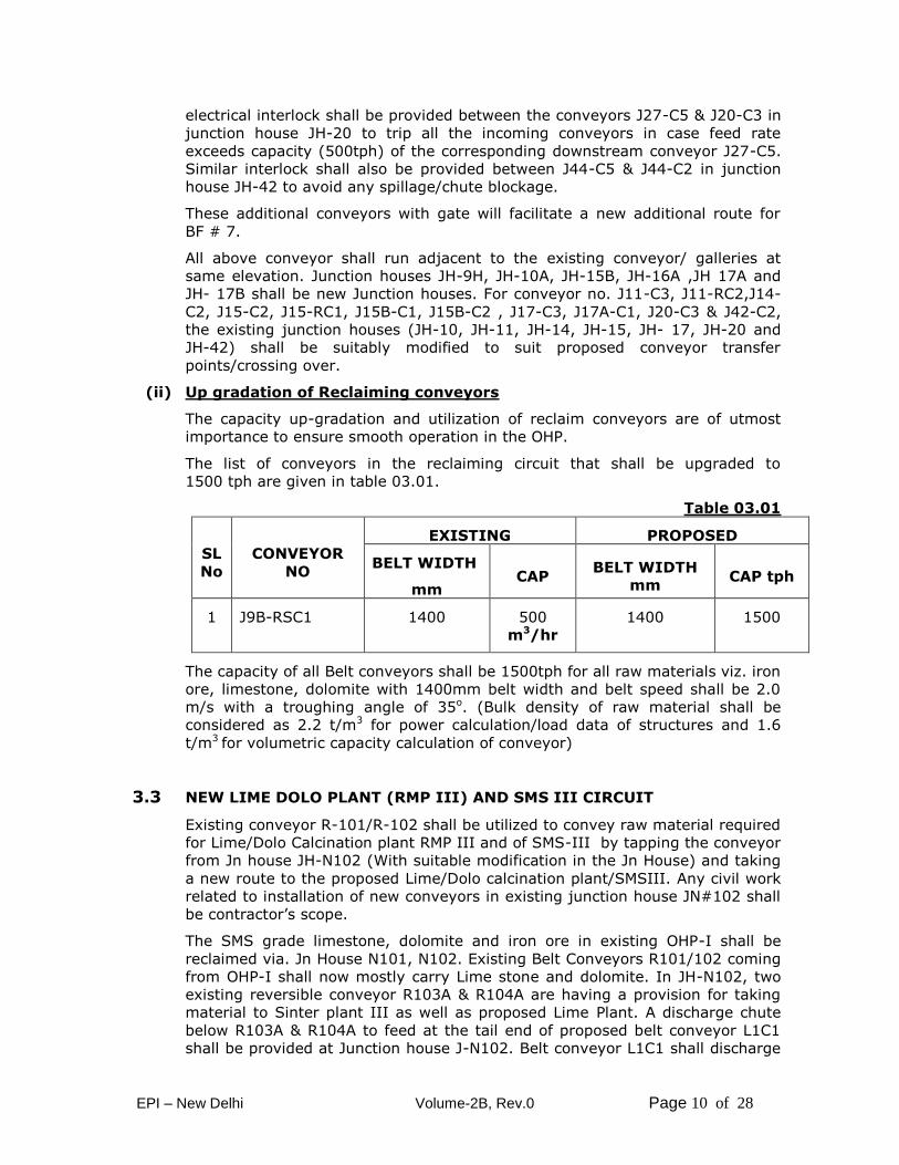
(ii) Up gradation of Reclaiming conveyors
The capacity up-gradation and utilization of reclaim conveyors are of utmost
importance to ensure smooth operation in the OHP.
The list of conveyors in the reclaiming circuit that shall be upgraded to
1500 tph are given in table 03.01.
Table 03.01
SL
No
CONVEYOR
NO
EXISTING PROPOSED
BELT WIDTH
mm CAP
BELT WIDTH
mm CAP tph
1 J9B-RSC1
1400
500
m3/hr
1400
1500
The capacity of all Belt conveyors shall be 1500tph for all raw materials viz. iron
ore, limestone, dolomite with 1400mm belt width and belt speed shall be 2.0
m/s with a troughing angle of 35o. (Bulk density of raw material shall be
considered as 2.2 t/m3 for power calculation/load data of structures and 1.6
t/m3 for volumetric capacity calculation of conveyor)
3.3 NEW LIME DOLO PLANT (RMP III) AND SMS III CIRCUIT
Existing conveyor R-101/R-102 shall be utilized to convey raw material required
for Lime/Dolo Calcination plant RMP III and of SMS-III by tapping the conveyor
from Jn house JH-N102 (With suitable modification in the Jn House) and taking
a new route to the proposed Lime/Dolo calcination plant/SMSIII. Any civil work
related to installation of new conveyors in existing junction house JN#102 shall
be contractor’s scope.
The SMS grade limestone, dolomite and iron ore in existing OHP-I shall be
reclaimed via. Jn House N101, N102. Existing Belt Conveyors R101/102 coming
from OHP-I shall now mostly carry Lime stone and dolomite. In JH-N102, two
existing reversible conveyor R103A & R104A are having a provision for taking
material to Sinter plant III as well as proposed Lime Plant. A discharge chute
below R103A & R104A to feed at the tail end of proposed belt conveyor L1C1
shall be provided at Junction house J-N102. Belt conveyor L1C1 shall discharge
EPI – New Delhi Volume-2B, Rev.0 Page 11 of 28
the material on L2C1 in junction house JH-L2. Conv L2C1 discharges onto
conveyor L3C1 which discharges onto L4C1 in JH L3.Conv L3C1 in turn
discharge material at Junction House JH-L4 to any of the two conveyors i.e.
L5C1 & L7C1 with the help of diverter Gate.
Thereafter, conveyor L7C1 will carry the material and transfer onto conveyor
L9C1. Conveyor L9C1 will carry the material up to Surge Bin building JHL9
through reversible shuttle conv. JL9RSC1. Surge bin building JHL9 shall have 3
nos. bunkers of minimum geometric capacity 190 cub m each for storing iron
ore lump/limestone /bauxite. Suitable rod gate and motorized rack and pinion
gates shall be fitted at the bottom of bunkers. Three (3) nos. VVF controlled
vibro feeders of 420 tph capacity each shall withdraw material from bunker and
discharge it onto conveyor L10C1 which shall convey up to Junction house JH
L10 for onward transportation to Surge Bin Building for SMS-III (Surge bins
with Vibro-feeder as shown in flow diagram at JH-L9 are in contractor’s scope.)
through SMS feeding conveyor. Conveyor L10C1 complete with discharge
facilities and junction house JH L10 shall be in the scope of contractor and SMS
feeding conveyor shall be in the scope of employer.
The other conveyor L5C1 shall receive material from conveyor L4C1 and
discharge at JH-L5 on to conv. L6C1 which shall convey up to junction house
JH-L6 and discharge onto lime plant feeding conveyor for onward transport to
Lime & Dolomite calcination plant RMP III. Conveyor L6C1 complete with
discharge facilities and junction house JH L6 shall be in the scope of contractor
.However lime plant feeding conveyor shall be in the scope of employer i.e.
BSP.
Calcined lime/dolomite is received from the day bins of lime/dolo product
storage building of RMP III onto conveyor L8C1.Conv. L8C1 discharges onto
conv. L9C2 in JH L8 which in turn discharges onto conveyor L10C1 in Surge Bin
building JH L9. This finished product of RMP III is transported to the junction
house JH L10 by conveyors L10C1 which shall also carry limestone, bauxite,
iron ore received directly from OHP I yard to SMS III. The scope of contractor
starts from tail end on conveyor L8C1 including skirt boards.
A fixed hopper of 8 cub m capacity on conveyor L10C1 near JH L9 with VVF
controlled vibro feeder of 420 tph capacity shall also be used to transport coke
fines as and when required in the storage bins of the bulk material charging
system of SMS III. Any other material e.g limestone/ DRI can also be
transported under emergency conditions through fixed hopper. Suitable ramp
shall be provided to unload the material over hopper.
EPI – New Delhi Volume-2B, Rev.0 Page 12 of 28
4.0 Technical Specifications of MVWS & IG-541 TYPE FIRE
PROTECTION WITH FDA PACKAGE
The scope of work of Fire Protection, Fire Detection & Alarm package includes;
4.1 Medium Velocity Water Spray (MVWS) & Automatic Clean
Agent (only IG-541-Inergen) System 4.2 Fire Detection & Alarm (FDA) System
4.1.0 Fire Protection System
Contract specification for complete fire protection system to be provided for the
OHP-Part B package is given below.
4.1.1 INTRODUCTION
In order to combat any occurrence of fire in various areas/units of the proposed
OHP-B package, an elaborate system of fire protection will be provided. The
system will be planned in conformity with Tariff Advisory Committee’ guidelines,
BIS and other relevant standard/codes.
Major Facilities envisaged are as following:
i/ Fire detection and alarm system (For details, Refer 4.2.0)
ii/ Water spray system comprising of MVWS & HVWS.
HVWS (High velocity water spray system) is not in the
scope of Bidder as there are no transformers greater or
equal to 10 MVA or having oil capacity 2000 liter. Hence
not in the scope of Bidder.
iii/ Automatic clean agent system (only IG 541- Inergen)
v/ Passive fire protection
4.1.2 SCOPE OF WORK AND SERVICES
The scope of work covers on turnkey basis design & engineering, supply, erection,
painting, testing, commissioning, and handing over of complete Fire Protection
System envisaged for the OHP-B of Bhilai Steel Plant 7.0 MT expansion. Two
years operation and maintenance spares, necessary tools, spanners etc. required
for regular operation / maintenance of systems will be supplied along with the
equipment.
Major work comprises of following:
a/ Fire fighting water at three points for MVWS system within the battery
limit of the contractor will be provided .However Contractor has to tap
water from this point and further design and supply of the entire fire
fighting facilities under their scope of work.
b/ Medium velocity water spray system (MVWS) for cable tunnels /
galleries in the OHP-B complex & HVWS (High velocity water spray
EPI – New Delhi Volume-2B, Rev.0 Page 13 of 28
system) for transformers will be provided if transformers are greater or
equal to 10 MVA or having oil capacity 2000 liter.
c/ Automatic Clean agent (only IG 541- Inergen) total flooding system for
computer rooms/ PLC room/control rooms.
d/ Microprocessor based Fire detection and Alarm system for electrical
premises and premises with automatic fire extinguishing system.
e/ Detector will be multi criteria combination of rate of rise heat detectors
and photo electric smoke detector. Ionization smoke detectors are not to
be accepted.
f/ Piping, valves, sluice gates etc.
g/ All civil & structural works
h/ All electrics.
i/ Controls and instrumentation.
j/ Shop and site painting for all equipments, pipes etc.
k/ Erection, testing, commissioning, PG test and Warranty for the complete
fire protection system.
l/ All the requirements of TAC for complete FPS will be incorporated by the
contractor in their scope irrespective of whether the details are
described in specification and/or shown in the drawings or not.
m/ Passive Fire Protection measures
The scope of work and services to be rendered by the Contractor for
installation of fire protection systems will include but will not be limited to
the following activities.
i/ Design & engineering, handling at site, preparation of erection drawings,
fabrication and erection as per approved drawings, site testing, painting,
commissioning and fulfillment of guarantee of all fire protection systems,
sub-systems and integrated systems as described above and also
covered in general technical specification.
ii/ Miscellaneous materials and services will include but not limited to the
following :
a/ All piping integral to and/or between any equipment furnished under this
specification, except as otherwise specified.
b/ Coupling guards for all exposed shafts and couplings.
c/ Foundation bolts, base plates, thrust blocks, duck-foot bends, matching
flanges, supporting materials and shims.
d/ All necessary instruments, power and control wiring integral to any
EPI – New Delhi Volume-2B, Rev.0 Page 14 of 28
equipment furnished under this specification. These will include terminal
blocks and integral wiring to the terminal blocks for equipment requiring
external connection.
e/ Earthing strips of all panels, & other fire fighting equipments supplied by
the contractor will be connected to the nearest earthing ring available at
site.
f/ Digging of underground trenches, laying of cables, laying of protection
slab/bricks over the cable routes, back filling of trench and levelling of
earth if required.
g/ GI pipes/ conduits and other accessories wherever required for laying of
cables.
h/ Other erection materials like cable supporting structures, channels,
brackets, clamps and other hardware materials, as required, for laying
of cables.
i/ All erection accessories, consumables and miscellaneous materials,
though not specifically indicated in this specification, but actually
required for completing the job in all respects.
j/ All necessary connections for hook-up with other system, if required as
per instruction of the employer.
k/ Erection, testing and commissioning materials.
l/ Initial fill of gas and other fire extinguishing media (including quantity
required for PG test) and demonstration.
m/ Valve chambers for all isolation valves.
n/ Housing for deluge valves.
o/ Cylinder battery racks.
4.1.3 DRAWINGS AND DOCUMENTS
Drawings/documents to be furnished
a/ Scope of work with general description of system and equipment offered
specifying the important features supplemented with scheme drawings.
The contractor has to give a confirmation with respect to the scope of
work as detailed in this specification. The description to be accompanied
by single line diagrams, and equipment layout to enable the
Employer to have a proper appreciation of the equipment and its
operation.
b/ Specification of equipment/material along with their makes/catalogues.
Approval certificate from authorizing bodies for various components of
the systems.
EPI – New Delhi Volume-2B, Rev.0 Page 15 of 28
c/ List of mandatory spares.
d/ List of special tools and tackles
e/ Certificate of approval from TAC and similar other authorizing body for
various component of the system.
4.1.4 TECHNICAL SPECIFICATION
Please refer General Technical Specification (GTS) for various fire protection
systems/facilities for detailed specification. However a brief description is
provided herewith.
Fire Detection & Alarm system (For details, Refer 4.2.0)
Water spray system comprising of MVWS & HVWS.
Medium velocity water spray system (MVWS) for cable tunnels / galleries in the
OHP-B complex & HVWS (High velocity water spray system) for transformers if
transformers are greater or equal to 10 MVA or having oil capacity 2000 litre.
Automatic Clean agent fire extinguishing system
For protection of Computer rooms/ PLC rooms/ important Control rooms
Automatic Clean agent fire extinguishing system (IG-541) will be provided.
These systems will function in automatic mode by actuation from Fire detection
& alarm system in the respective premises. There will be provision for manual
operation also with a selector toggle. When detectors detect fire, the signal will
be communicated to the main control panel, which shows the address (along
with location) of the actuated detector. On confirmation of fire by next detector
falling in different software zone in the same premises, the respective Air-
conditioning & Ventilation system will first trip and evacuation alarm signal will
appear in the premises provided with these system followed by actual discharge
of the gas(after time lag). The system will be designed according NFPA 2001.
100% reserve cylinders will be provided for all systems.
4.1.5 Passive Fire Protection System
Passive fire protection is an integral part of a complete fire protection system
and are essential for prevention of spread of fire through openings in walls or
floors. Following measures will be provided:
Fire Retardant Coating/Painting of cables
For vertical run of cables -Whole length of cable will have fire retardant
water based in-tumescent / ablative compound non toxic resistance to
hydrocarbon, acid, Alkali attack, water & oil resistance.
For horizontal run of cables –1 m length of fire retardant coating will be
provided at every 20 m interval. Wherever cables cross any partition
EPI – New Delhi Volume-2B, Rev.0 Page 16 of 28
wall, floor or pass through any opening, coating will be provided for at
least 1 m length on either side.
Fire rating of coating materials for cables will be 2.5 hrs.
Sealing of Cable Openings
Partitions in Cable Channels/tunnels/galleries
Fire door
Fire rating of fire door will be 3 hrs as per GS.
4.1.6 ERECTION, TESTING, COMMISSIONING & PERFORMANCE GUARANTEE
The erection of all plant and equipment will be carried out according to the
latest engineering practices and according to the working drawings, erection
specification, instructions etc. duly approved by the Employer. The Contractor
will carry out the work in the presence and/or as per the instructions of site
engineer/supervisory personnel deputed by the Employer. The erection will be
carried out by highly skilled workmen.
The Contractor will be responsible for paying strict attention to statutory
regulations for prevention of accidents and to other safety rules. The
regulations for prevention of accidents will be deployed at appropriate places
and should be distinctly visible to all personnel working in the area.
The Contractor will supply all required consumables, construction and erection
materials, petrol, diesel oil, kerosene, solvents, sealing compound, tapes,
brazing and soldering materials, welding and brazing gases, erection bolts, nuts
and packing sheets/compounds, temporary supports, wooden blocks, spacers,
templates, jute and cotton wastes, sand and emery paper etc. as required for
the satisfactory completion of work.
The Contractor will make his own arrangement for storing, handling the
equipment and pipelines at the stores and transporting it to the site for
installation. In addition to the above, the contractor will follow all the relevant
erection clauses/conditions stated under various chapters in the contract
document.
Contractor has taken note that training to fire engineers for maintenance/
checking of FDA and fire fighting system at OEM training centre. Training on fire
risk analysis and its mitigation in the new OHP technology will be provided at
site.
The contractor will provide all tools, labour including necessary subsistence,
erection supervision, equipment, materials, accessories, to erect/install and
make ready for operation & functionally complete the total fire protection
system as described and specified in this document.
EPI – New Delhi Volume-2B, Rev.0 Page 17 of 28
4.1.7 Testing, Commissioning & Performance Guarantee of the complete
system.
Testing
Contractor has taken note that all fire protection system will be tested and
commissioned in presence of CFO / Fire Brigade representative or MECON
before the commissioning of main units.
All tests and inspection of the installation will be done in conformity with the
functional and statutory requirement of the system. The contractor will furnish
a detailed testing and commissioning procedure for all the systems for approval
by the employer. As soon as a given facility or a portion thereof is completed
and ready to energize and start-up, the employer may test run and operate it
without relieving the contractor of his responsibility or guarantee.
4.1.8 Start-up and commissioning
i/ Contractor will provide the services of all technicians, erection and
start-up engineers necessary to bring the complete installation of fire
protection system into operation.
The contractor will be responsible for the integrated commissioning of
the plant & equipment supplied by him including trials, commissioning
and demonstration of performance guarantee test.
ii/ The Contractor will render the following services:
a) Prepare equipment for trial runs and start-up
b) Start-up and commissioning of equipment.
c) Preliminary operation, initial operation, trial operation and Final
acceptance test.
The Contractor will be required to clean up the equipment and
surrounding area and prepare it for trial runs and operation.
Priming connections, cooling water supply to bearings, lubrication piping to
bearings, stuffing box jackets and sealing glands of all rotating equipment
will be checked by the contractor.
Sequence checking of all control systems, pneumatic and cable connections,
checking operation of all interlocks and protective devices will be done by the
contractor.
Blow down of all piping systems, installations and removing strainers in piping
and equipment, as required will be done by the contractor.
Calibration and adjustment of relay settings, instruments etc., disconnecting
and reconnecting the driven and driving parts of any equipment and drives,
as required, during the trial runs and rectification, if any will be done by the
contractor.
EPI – New Delhi Volume-2B, Rev.0 Page 18 of 28
The Contractor will provide personnel as required for assisting starting up
and commissioning of equipment as well as adjustments, repairs and
rectifications of defects in erection of the equipment during commissioning of
the equipment and upto final acceptance.
4.1.9 Commissioning
On completion of the trial operation, all the systems will be under observation
in operative condition. The Contractor will provide skilled personnel including
necessary tools and consumables wherever necessary to rectify the deficiencies
observed.
4.1.10 Performance guarantee
The performance guarantee tests will be completed within a time schedule to be
mutually agreed upon between the Employer and the Contractor. Details of
the performance tests, test procedures and test schedules for the
demonstration of the performance guarantee on NFPA Codes/TAC Regulations
will be submitted to the Employer and will be mutually agreed upon.
The Contractor will conduct the operation during the performance tests and
will take full responsibility of the operations.
If the Contractor is unable to achieve the performance values as a whole or in
part during the performance tests, the Contractor will repeat the tests for
demonstrating the performance values. Before repeating the tests the
Contractor will take any and all measures as may be needed, at his own cost in
order that the performance values can be achieved.
If even with two repetitive tests and if necessary, by using additional operating
personnel from the Contractor's crew and at his own expenses, the
performance values are not reached the Contractor will undertake at his own
cost such modification or replacement as are considered necessary to obtain
the performance guarantee values and the responsibility to demonstrate
performance guarantee will continue to remain with the Contractor till so
established.
4.2.0 Fire Detection & Alarm (FDA) System
This section covers major features of Fire Detection & Alarm system to be
supplied by Contractor for Augmentation of Raw material receipt & handling
facilities – Part – B.
The Contractor shall refer to General Technical Specification for Fire Detection &
Alarm system for detailed specification of equipment / components. This
Technical Specification (TS), General technical Specification (GTS) including
Preferred Makes for Equipment and supplies and other attached documents
considered, as a whole shall comprise the complete Contract Specification.
These are complementary and anything laid down in one and not in other will
be deemed as binding, as though laid down in the Contract specification as a
EPI – New Delhi Volume-2B, Rev.0 Page 19 of 28
whole. In case of conflict between the Technical specification and GTS, the
Technical specification (TS) shall prevail.
4.2.1 Scope of Work
The scope of work of Contractor shall cover design, basic and detailed
engineering, supply, submission of drawings for approval, manufacture, testing,
inspection by Purchaser/Consultant, packing, loading, forwarding, delivery at
Plant site, loading/unloading, storage, handling of material / equipment for
erection testing, commissioning, PG test, PAT/FAT and liquidating the all defects
related to FDA (Fire detection & Alarm) equipment for complete & satisfactory
operation of the system on Turnkey basis.
Any item or equipment not specifically mentioned but essential for proper
installation, operation, maintenance and safety of plant, equipment and
personnel shall be included by the Contractor in his scope of work
The scope of work for this package shall include but not limited to the following:
Intelligent, microprocessor based, addressable type automatic fire detection
and alarm (FDA) system for the following premises shall be provided.
i) All HT/LTSS, cable basement/cellar, cable tunnel and concrete cable channels,
conveyors, MCC Rooms, Hydraulic rooms, Control rooms, Electrical premises
etc including their associated utility areas like offices, Pantry, AHU rooms,
Stairs etc. shall be covered under this system.
ii)Details of Microprocessor Based Analogue Addressable Type Fire
Detection And Alarm System (FDAS).
The scope shall broadly cover the following and also shall include such of those
items and accessories not mentioned here but required for satisfactory
operation of the system.
Intelligent, microprocessor based, addressable type automatic fire
detection and alarm system for all MCC rooms, HT/LT substation
rooms, Cable cellar, Transformer rooms, Control rooms using smoke
detectors, heat detectors with cross zoning.
Fire Alarm system shall be supplied along with HMI and required
software loaded.
The Fire Alarm panel shall have auto Dialer facility to inform to central
fire station of BSP through plant telephone network. However the FDA
panel shall have Ethernet connectivity port with TCP/IP protocol to
connect to plant LAN in future. The supplier of this package shall keep
necessary software and hardware in his scope of supply.
EPI – New Delhi Volume-2B, Rev.0 Page 20 of 28
Provision for interlocking of FDA system with Fire Fighting System
shall be kept in Fire Alarm control panel. Details shall be provided
during detail engineering stage.
INTERLOCKING OF FDA SYSTEM WITH FIRE FIGHTING SYSTEM
Medium Velocity Water Spray (MVWS) envisaged for cable galleries &
tunnels. In the event of fire in these premises, the detection system
shall give signal to Main Fire Alarm Control Panel which in turn will
actuate the solenoid of the deluge valve concerned. Apart from this,
HVWS system which has been envisaged for out-door transformer of
capacity more than 10 MVA OR having oil more than 2000 Litre will
have provision for annunciation in the FACP. The scope of work of
Contractor shall also include power supply & cabling to Solenoid
valves & taking feedback of pressure switches through cabling. The
Contractor shall be fully responsible for testing & commissioning of
water spraying system with Deluge valves as per specification for
providing Fire Hydrant system & water spraying with Deluge valves.
All annunciation of the Deluge valves & accessories will come in the
Fire Alarm panel along with automatic control.
Automatic Carbon dioxide system & Clean agent system – CO2
system has been envisaged for oil cellars of shops & mills whereas
Clean agent system has been considered for Computer rooms / PLC
Rooms / main control rooms (in various technological units). These
areas are covered by network of smoke & heat detectors. When
detectors detect fires, the signal is communicated to the main control
panel, which shows the address (along with location) of the actuated
detector. On detection of fire the respective hooters of the area will
be actuated. On confirmation if fire by next detector falling in
different software zone in the same premises, AC/Ventilation system
will trip & evacuation alarm signal will appear in the premises
provided with the system. Gas will be discharged automatically in the
affected premises after a time lag of 30 seconds. There will also be
selector switch for manual and automatic actuation of the system.
Break glass type manual call points with chain & hammer (with or
without hand set) / Pull down type manual call point.
Manual call points will also be provided at every 50 m interval in the
bays, rooms & Jn. House. Minimum one number of manual call point
shall be provided for each entrance / exit.
EPI – New Delhi Volume-2B, Rev.0 Page 21 of 28
Central control panel. The CPU of the panel shall co-ordinate function
of various loops. Failure of CPU shall not stop detection of fire by
various loops and annunciation in display unit and communicating to
Graphics station and remote LAN workstation. The software of the
panel shall be upgradeable through easy software downloads required
from time to time.
Power supply equipment.
Power supply for the FDA system shall be obtained from the
Automation UPS system
Power supply from UPS system for Local Graphics computer and
printer.
Siren and Accessories.
The Contractor shall work out Bill of quantities to cover plant and
equipment in various zones as per layout drawings.
For other details of FDA system equipment, cables & other
components, accessories etc, refer GTS.
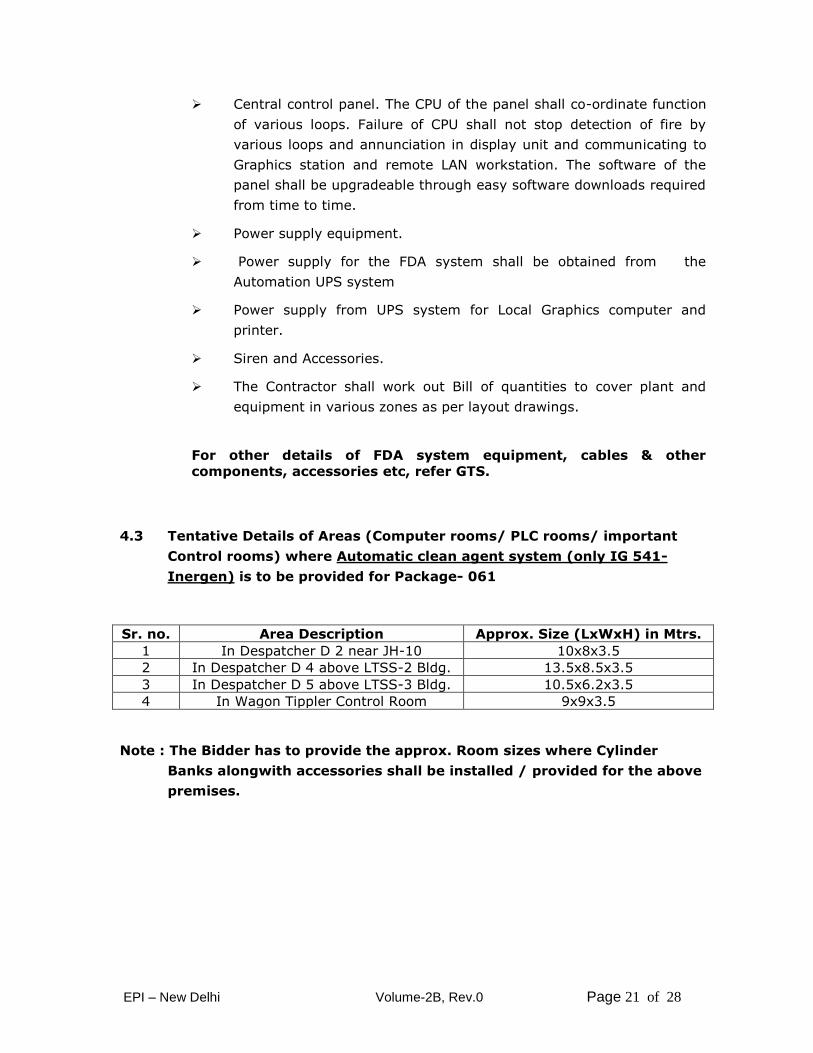
4.3 Tentative Details of Areas (Computer rooms/ PLC rooms/ important
Control rooms) where Automatic clean agent system (only IG 541-
Inergen) is to be provided for Package- 061
Sr. no. Area Description Approx. Size (LxWxH) in Mtrs.
1 In Despatcher D 2 near JH-10 10x8x3.5
2 In Despatcher D 4 above LTSS-2 Bldg. 13.5x8.5x3.5
3 In Despatcher D 5 above LTSS-3 Bldg. 10.5x6.2x3.5
4 In Wagon Tippler Control Room 9x9x3.5
Note : The Bidder has to provide the approx. Room sizes where Cylinder
Banks alongwith accessories shall be installed / provided for the above
premises.
EPI – New Delhi Volume-2B, Rev.0 Page 22 of 28
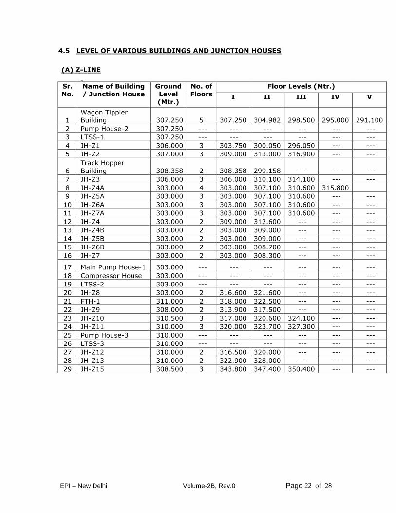
4.5 LEVEL OF VARIOUS BUILDINGS AND JUNCTION HOUSES
(A) Z-LINE
Sr.
No.
Name of Building
/ Junction House
Ground
Level
(Mtr.)
No. of
Floors
Floor Levels (Mtr.)
I II III IV V
1
Wagon Tippler
Building 307.250 5 307.250 304.982 298.500 295.000 291.100
2 Pump House-2 307.250 --- --- --- --- --- ---
3 LTSS-1 307.250 --- --- --- --- --- ---
4 JH-Z1 306.000 3 303.750 300.050 296.050 --- ---
5 JH-Z2 307.000 3 309.000 313.000 316.900 --- ---
6
Track Hopper
Building 308.358 2 308.358 299.158 --- --- ---
7 JH-Z3 306.000 3 306.000 310.100 314.100 --- ---
8 JH-Z4A 303.000 4 303.000 307.100 310.600 315.800
9 JH-Z5A 303.000 3 303.000 307.100 310.600 --- ---
10 JH-Z6A 303.000 3 303.000 307.100 310.600 --- ---
11 JH-Z7A 303.000 3 303.000 307.100 310.600 --- ---
12 JH-Z4 303.000 2 309.000 312.600 --- --- ---
13 JH-Z4B 303.000 2 303.000 309.000 --- --- ---
14 JH-Z5B 303.000 2 303.000 309.000 --- --- ---
15 JH-Z6B 303.000 2 303.000 308.700 --- --- ---
16 JH-Z7 303.000 2 303.000 308.300 --- --- ---
17 Main Pump House-1 303.000 --- --- --- --- --- ---
18 Compressor House 303.000 --- --- --- --- --- ---
19 LTSS-2 303.000 --- --- --- --- --- ---
20 JH-Z8 303.000 2 316.600 321.600 --- --- ---
21 FTH-1 311.000 2 318.000 322.500 --- --- ---
22 JH-Z9 308.000 2 313.900 317.500 --- --- ---
23 JH-Z10 310.500 3 317.000 320.600 324.100 --- ---
24 JH-Z11 310.000 3 320.000 323.700 327.300 --- ---
25 Pump House-3 310.000 --- --- --- --- --- ---
26 LTSS-3 310.000 --- --- --- --- --- ---
27 JH-Z12 310.000 2 316.500 320.000 --- --- ---
28 JH-Z13 310.000 2 322.900 328.000 --- --- ---
29 JH-Z15 308.500 3 343.800 347.400 350.400 --- ---
EPI – New Delhi Volume-2B, Rev.0 Page 23 of 28
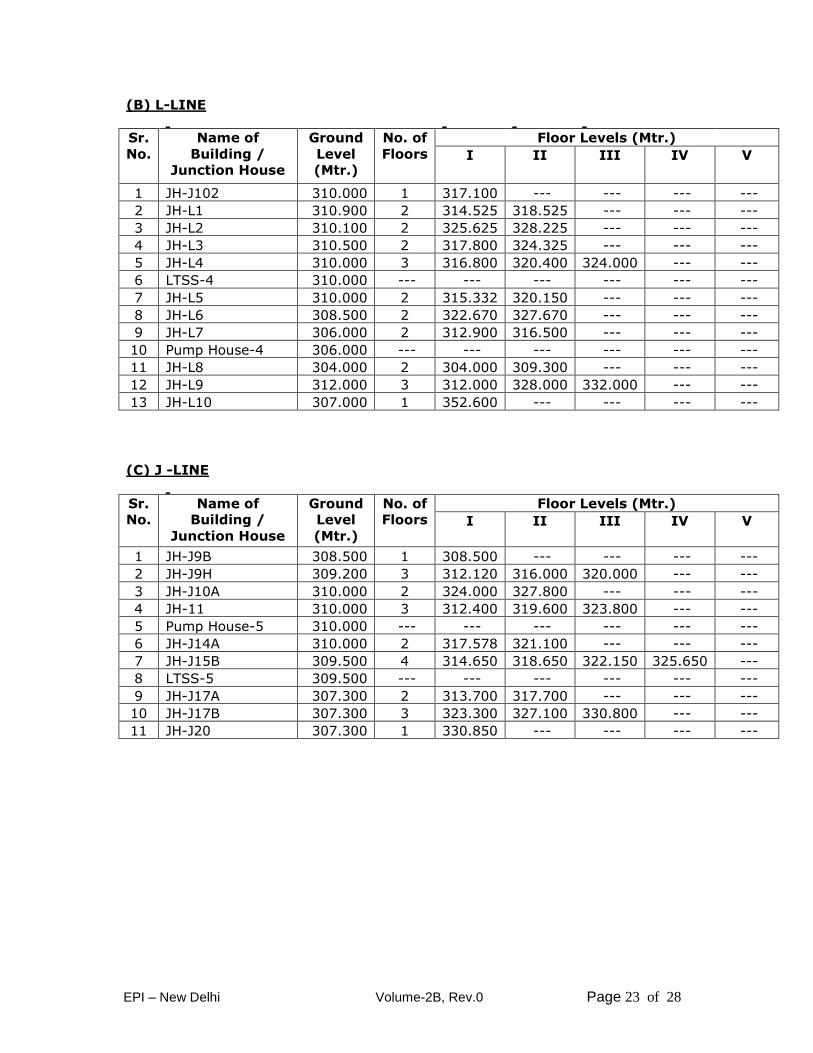
(B) L-LINE
Sr.
No.
Name of
Building /
Junction House
Ground
Level
(Mtr.)
No. of
Floors
Floor Levels (Mtr.)
I II III IV V
1 JH-J102 310.000 1 317.100 --- --- --- ---
2 JH-L1 310.900 2 314.525 318.525 --- --- ---
3 JH-L2 310.100 2 325.625 328.225 --- --- ---
4 JH-L3 310.500 2 317.800 324.325 --- --- ---
5 JH-L4 310.000 3 316.800 320.400 324.000 --- ---
6 LTSS-4 310.000 --- --- --- --- --- ---
7 JH-L5 310.000 2 315.332 320.150 --- --- ---
8 JH-L6 308.500 2 322.670 327.670 --- --- ---
9 JH-L7 306.000 2 312.900 316.500 --- --- ---
10 Pump House-4 306.000 --- --- --- --- --- ---
11 JH-L8 304.000 2 304.000 309.300 --- --- ---
12 JH-L9 312.000 3 312.000 328.000 332.000 --- ---
13 JH-L10 307.000 1 352.600 --- --- --- ---
(C) J -LINE
Sr.
No.
Name of
Building /
Junction House
Ground
Level
(Mtr.)
No. of
Floors
Floor Levels (Mtr.)
I II III IV V
1 JH-J9B 308.500 1 308.500 --- --- --- ---
2 JH-J9H 309.200 3 312.120 316.000 320.000 --- ---
3 JH-J10A 310.000 2 324.000 327.800 --- --- ---
4 JH-11 310.000 3 312.400 319.600 323.800 --- ---
5 Pump House-5 310.000 --- --- --- --- --- ---
6 JH-J14A 310.000 2 317.578 321.100 --- --- ---
7 JH-J15B 309.500 4 314.650 318.650 322.150 325.650 ---
8 LTSS-5 309.500 --- --- --- --- --- ---
9 JH-J17A 307.300 2 313.700 317.700 --- --- ---
10 JH-J17B 307.300 3 323.300 327.100 330.800 --- ---
11 JH-J20 307.300 1 330.850 --- --- --- ---
EPI – New Delhi Volume-2B, Rev.0 Page 24 of 28
5.0 SPARES (A) Commissioning Spares and Insurance Spares
Supply of commissioning spares and insurance spares as required shall be
in scope of supply of the Bidder alongwith the equipment. The list of
commissioning spares and the insurance spares as per the format as given
in SBD shall be furnished alongwith the tender. It shall cover requirements
of erection, cold tests, startup and initial operation of the plant till
integrated testing & successful commissioning and commencement of
commercial production up to a period of six months. Any leftover
commissioning spares shall be the property of the Purchaser. Any
commissioning spares required over and above the list given by the Bidder
shall have to be provided by the Bidder free of cost up to the successful
commissioning & commencement of commercial production of the plant and
equipment. The Bidder shall supply adequate insurance spares to ensure
smooth operation and maintenance of the plant.
(B) Consumables
The Bidder shall supply all consumables such as initial fill of lubricants, oils,
grease, chemicals, refractories, resins etc. as required to complete the plant
till commissioning and shall have a shelf life of minimum one year. The
scope of consumables shall include electrodes, shims, packings, bolts, nuts,
gaskets, rivets, washers etc. The Bidder shall fulfill the requirement given
in SBD.
The Bidder shall also furnish Indian equivalent of oils, lubricants,
refractories and other consumables along with necessary specifications,
drawings, catalogues etc. to enable the Purchaser to procure them from
indigenous sources.
The Bidder shall indicate the annual requirement of all such consumables.
(C) Operating, Maintenance and Two Years’ Spares:
(1) The Bidder shall ensure the interchangeability of the parts wherever
possible. The Bidder shall furnish an itemized list of interchangeable
spares as given in SBD.
(2) The list of spares as necessary and recommended by the respective
manufacturer for two years’ of reliable and trouble free operation and
maintenance of all equipment under this package shall be in the scope of
the Bidder. The same shall be quoted separately. In the event of order
the successful Bidder shall furnish complete specification of the same.
(3) Spares list giving complete list of the replaceable parts, fully illustrated,
shall be supplied. The list shall include the following information.
Item designation
Reference drawings
EPI – New Delhi Volume-2B, Rev.0 Page 25 of 28
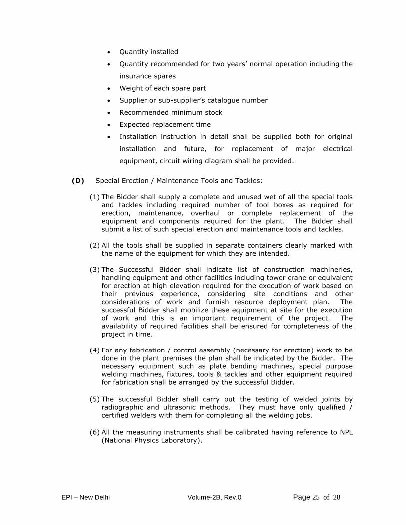
Quantity installed
Quantity recommended for two years’ normal operation including the
insurance spares
Weight of each spare part
Supplier or sub-supplier’s catalogue number
Recommended minimum stock
Expected replacement time
Installation instruction in detail shall be supplied both for original
installation and future, for replacement of major electrical
equipment, circuit wiring diagram shall be provided.
(D) Special Erection / Maintenance Tools and Tackles:
(1) The Bidder shall supply a complete and unused wet of all the special tools
and tackles including required number of tool boxes as required for
erection, maintenance, overhaul or complete replacement of the
equipment and components required for the plant. The Bidder shall
submit a list of such special erection and maintenance tools and tackles.
(2) All the tools shall be supplied in separate containers clearly marked with
the name of the equipment for which they are intended.
(3) The Successful Bidder shall indicate list of construction machineries,
handling equipment and other facilities including tower crane or equivalent
for erection at high elevation required for the execution of work based on
their previous experience, considering site conditions and other
considerations of work and furnish resource deployment plan. The
successful Bidder shall mobilize these equipment at site for the execution
of work and this is an important requirement of the project. The
availability of required facilities shall be ensured for completeness of the
project in time.
(4) For any fabrication / control assembly (necessary for erection) work to be
done in the plant premises the plan shall be indicated by the Bidder. The
necessary equipment such as plate bending machines, special purpose
welding machines, fixtures, tools & tackles and other equipment required
for fabrication shall be arranged by the successful Bidder.
(5) The successful Bidder shall carry out the testing of welded joints by
radiographic and ultrasonic methods. They must have only qualified /
certified welders with them for completing all the welding jobs.
(6) All the measuring instruments shall be calibrated having reference to NPL
(National Physics Laboratory).
EPI – New Delhi Volume-2B, Rev.0 Page 26 of 28
(7) All tools and tackles, apparatus, special instruments required for erection,
testing, commissioning and establishment of the Performance Guarantee
Test, measurements required for establishing the pollution control norms
and such other instruments, as required, shall be arranged by the
successful Bidder. After commissioning, the successful Bidder shall
handover all the special tools & tackles to the Purchaser as per the
requirement given in SBD.
(8) The successful Bidder shall supply all required consumables, initial fill, oil,
lubricants, construction and erection materials including but not limited to
shims, packing plates, joining compounds, kerosene, solvents, sealing
compounds, tapes, connectors, brazing and soldering materials, welding
and brazing gases and rods, electrodes and wires, erection bolts, nuts,
rivets, piano wire, packing sheet and packing compounds, temporary
supports, spacer templates, jute and cotton waste cloth, sand and emery
paper etc. for the commissioning of the plant.
(9) For load testing of handling equipment, loads shall have to be arranged by
the successful Bidder. Electrical/ operation tests, as per standard practice,
shall also be arranged and completed by them.
(10) All materials, equipment, tools, tackles etc. brought at site by the
successful Bidder within the plant area shall not be removed without the
written permission of the Purchaser. Similarly, all enabling works
built/erected and/or acquired by them within the plant premises shall not
be dismantled and removed without the written permission of the
Purchaser.
(E) Information/ Data on Spares and Consumables
The list of Spares & consumables shall be furnished by the successful Bidder
as required in SBD. However, the successful Bidder shall furnish various
information regarding spares, consumables, tools & tackles etc. as per the
schedules indicated in chapter 12 of this Technical Specification.

EPI – New Delhi Volume-2B, Rev.0 Page 27 of 28
DATA SHEETS
EPI – New Delhi Volume-2B, Rev.0 Page 28 of 28
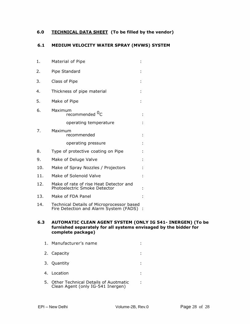
6.0 TECHNICAL DATA SHEET (To be filled by the vendor)
6.1 MEDIUM VELOCITY WATER SPRAY (MVWS) SYSTEM
1. Material of Pipe :
2. Pipe Standard :
3. Class of Pipe :
4. Thickness of pipe material :
5. Make of Pipe :
6. Maximum recommended 0C : operating temperature : 7. Maximum recommended : operating pressure : 8. Type of protective coating on Pipe : 9. Make of Deluge Valve : 10. Make of Spray Nozzles / Projectors : 11. Make of Solenoid Valve : 12. Make of rate of rise Heat Detector and Photoelectric Smoke Detector : 13. Make of FDA Panel : 14. Technical Details of Microprocessor based Fire Detection and Alarm System (FADS) :
6.3 AUTOMATIC CLEAN AGENT SYSTEM (ONLY IG 541- INERGEN) (To be
furnished separately for all systems envisaged by the bidder for
complete package)
1. Manufacturer’s name :
2. Capacity :
3. Quantity :
4. Location :
5. Other Technical Details of Auotmatic : Clean Agent (only IG-541 Inergen)