telsinex installation guide ver2.0
TRANSCRIPT

i
TelsiNex™
Version S480
TelsiNex Installation GuideSeptember 2006
ii
This document is for informational purposes only and the content is subject to change without notice. TELSIMA MAKES NO WARRANTIES, EXPRESS OR IMPLIED, IN THIS document. Telsima, StarMAX, TelsiNex, TRUFLE, OptiFlow and OptiView and are registered trademarks of Telsima Corporation. All other product and service names referenced herein are either trade names or service marks of Telsima Corporation in the United States and/or other countries. The other names of actual companies and products mentioned herein may be the trademarks of their respective owners. Copyright 2006 Telsima Corporation. All rights reserved. The information contained in this document is subject to change without notice. Reproduction, adaptation or translation without prior permission is prohibited except as allowed under the copyright law.
iii
Table of Contents
PrefaceAudience . . . . . . . . . . . . . . . . . . . . . . . . . . . . . . . . . . . . . . . . . . . . . . . . . . . . . . . . vRelated Information . . . . . . . . . . . . . . . . . . . . . . . . . . . . . . . . . . . . . . . . . . . . . . . vContact Us . . . . . . . . . . . . . . . . . . . . . . . . . . . . . . . . . . . . . . . . . . . . . . . . . . . . . . . vConventions . . . . . . . . . . . . . . . . . . . . . . . . . . . . . . . . . . . . . . . . . . . . . . . . . . . . . viAcronyms. . . . . . . . . . . . . . . . . . . . . . . . . . . . . . . . . . . . . . . . . . . . . . . . . . . . . . . vii
Chapter 1 Overview of TelsiNex Installation1.1 Overview of Installation Process. . . . . . . . . . . . . . . . . . . . . . . . . . . . 1-1
Chapter 2 Preparing for Installation2.1 Checking the Contents of the Package . . . . . . . . . . . . . . . . . . . . . . . 2-12.2 Additional Equipment Required. . . . . . . . . . . . . . . . . . . . . . . . . . . . 2-32.3 Ensuring Safety Before Starting the Installation . . . . . . . . . . . . . . . 2-32.3.1 Checking Environmental and Site Requirements . . . . . . . . . . 2-32.3.2 Checking Electrical Requirements . . . . . . . . . . . . . . . . . . . . . . . 2-42.3.3 Checking Grounding Arrangements . . . . . . . . . . . . . . . . . . . . . 2-4
Chapter 3 Mounting and Grounding TelsiNex3.1 Mounting TelsiNex . . . . . . . . . . . . . . . . . . . . . . . . . . . . . . . . . . . . . . . 3-13.2 Grounding TelsiNex . . . . . . . . . . . . . . . . . . . . . . . . . . . . . . . . . . . . . . 3-2
Chapter 4 Connecting Cables4.1 Connecting TelsiNex to E1 I/O and Bearer Line . . . . . . . . . . . . . . 4-14.2 Connecting Power Cables to DC Power Supplies . . . . . . . . . . . . . 4-24.3 Connecting TelsiNex to a Management Console . . . . . . . . . . . . . . 4-34.3.1 Connecting TelsiNex to a Computer . . . . . . . . . . . . . . . . . . . . . 4-44.3.1.1 Connecting a Computer Through RS232-A Port . . . . . . . . 4-44.3.1.2 Connecting a Computer Through the Ethernet Port . . . . . 4-64.4 Connecting TelsiNex to Alarm Contacts . . . . . . . . . . . . . . . . . . . . . 4-7
iv
4.5 Connecting TelsiNex to External Clocks . . . . . . . . . . . . . . . . . . . . . 4-8
Chapter 5 Powering On TelsiNex5.1 Ensuring Safety Before Powering On TelsiNex . . . . . . . . . . . . . . . 5-15.2 Switching on TelsiNex and Verifying Proper Functioning. . . . . . 5-25.2.1 LED Status During Booting . . . . . . . . . . . . . . . . . . . . . . . . . . . . 5-35.2.2 LED Status During Operation . . . . . . . . . . . . . . . . . . . . . . . . . . 5-55.3 Testing TelsiNex as a Link . . . . . . . . . . . . . . . . . . . . . . . . . . . . . . . . . 5-75.3.1 Checking Clock Synchronization . . . . . . . . . . . . . . . . . . . . . . . . 5-75.3.2 Checking the Line Report for Bearer . . . . . . . . . . . . . . . . . . . . . 5-75.3.3 Checking Line Report for Trunk E1s . . . . . . . . . . . . . . . . . . . . . 5-75.3.4 Checking End-to-End Connectivity of all E1s . . . . . . . . . . . . . 5-85.3.5 Checking End-to-End Connectivity for Bearer . . . . . . . . . . . . 5-85.3.6 Performing Loop Make and Break Test for Bearer on Both Ends
5-85.3.7 Checking Fluctuation of Media . . . . . . . . . . . . . . . . . . . . . . . . . 5-8
Chapter 6 Booting and Configuring Basic Parameters6.1 Booting TelsiNex . . . . . . . . . . . . . . . . . . . . . . . . . . . . . . . . . . . . . . . . . 6-16.2 Accessing TelsiNex Through Telnet. . . . . . . . . . . . . . . . . . . . . . . . . 6-16.3 Configuring Basic Parameters. . . . . . . . . . . . . . . . . . . . . . . . . . . . . . 6-26.3.1 Setting the Name . . . . . . . . . . . . . . . . . . . . . . . . . . . . . . . . . . . . . 6-26.3.2 Setting the Clock . . . . . . . . . . . . . . . . . . . . . . . . . . . . . . . . . . . . . . 6-26.3.3 Setting Transparent Channels . . . . . . . . . . . . . . . . . . . . . . . . . . 6-36.3.4 Setting PCM Mode . . . . . . . . . . . . . . . . . . . . . . . . . . . . . . . . . . . . 6-4
Chapter 7 Troubleshooting7.1 Replacing the Power Supply . . . . . . . . . . . . . . . . . . . . . . . . . . . . . . . 7-1
Appendix A PinoutsA.1 Modem Port Pinout . . . . . . . . . . . . . . . . . . . . . . . . . . . . . . . . . . . . . .A-1A.2 RJ-E1 Port Pinout . . . . . . . . . . . . . . . . . . . . . . . . . . . . . . . . . . . . . . . .A-3A.3 Alarm Port Pinout . . . . . . . . . . . . . . . . . . . . . . . . . . . . . . . . . . . . . . .A-4
v
Preface
This guide helps you to install TelsiNex™ and configure its basic parameters to bring it in functional condition.
AudienceThis guide is intended for use by qualified service personnel who are responsible for installing TelsiNex. The installation of this system requires that the service personnel hold appropriate technical training and experience and be aware of the potential hazards involved in installing and replacing TelsiNex.
Related InformationFor more information, refer to the following:
• TelsiNex User’s Guide
• TelsiView Installation Guide
• TelsiView User’s Guide
Contact UsIf you purchased a service program from Telsima, you can get help at any time by calling Telsima:
USA and Europe: +1-408-625-3600
India, Bangalore: +91-80-30573901
India, Gurgaon: +91-124-4300338
Telsima would like to know if you found the document useful. If you have any feedback or comments on this document, send us email at

vi
[email protected]. Please mention the software, version of the software, title of the document, and part number of the document in your message.
You can also send us your comments by mail at:Telsima Inc.3945, Freedom Circle,Suite No, 130, Santa Clara,CA 95044444, USA.
ConventionsThe following conventions are used in the document to help you identify special terms:
Convention Usage Example
Bold The following screen elements:
Button
List
Drop-down menu
Click OK.
Italic Book titles and emphasis Refer to Concepts Guide for more information.
monospace Code samples and commands To run the installer, enter the following command:
C:\ run installer.bat
monospace italic Variable in a command or code that you may replace with other values, as required
To make a new directory, enter:
prompt > mkdir new_direcotry_name
<> Mandatory parameters in a command
set dcme serialnum <serialnum_string>
() Acceptable values for a parameter
set dcme clockselect <sys|ber|trk trunkId (1-16)>
[ ] Optional parameters C:\ run installer.bat [-p]
| Mutually exclusive choices in a command or code
C:\ run installer.bat [-p | -r]
vii
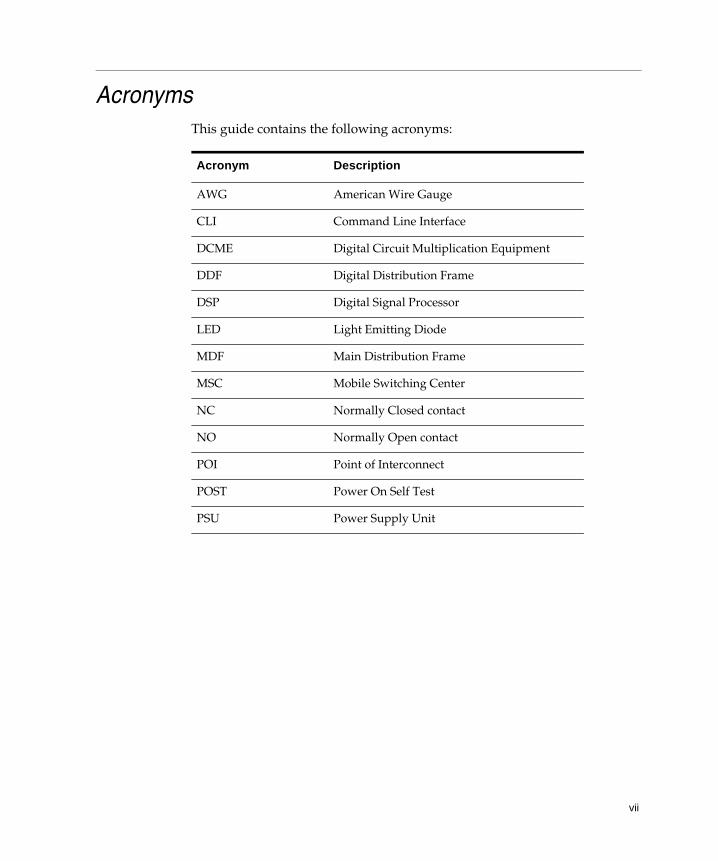
AcronymsThis guide contains the following acronyms:
Acronym Description
AWG American Wire Gauge
CLI Command Line Interface
DCME Digital Circuit Multiplication Equipment
DDF Digital Distribution Frame
DSP Digital Signal Processor
LED Light Emitting Diode
MDF Main Distribution Frame
MSC Mobile Switching Center
NC Normally Closed contact
NO Normally Open contact
POI Point of Interconnect
POST Power On Self Test
PSU Power Supply Unit

viii
Overview of TelsiNex Installation 1-1
CHAPTER
1
Overview of TelsiNex Installation
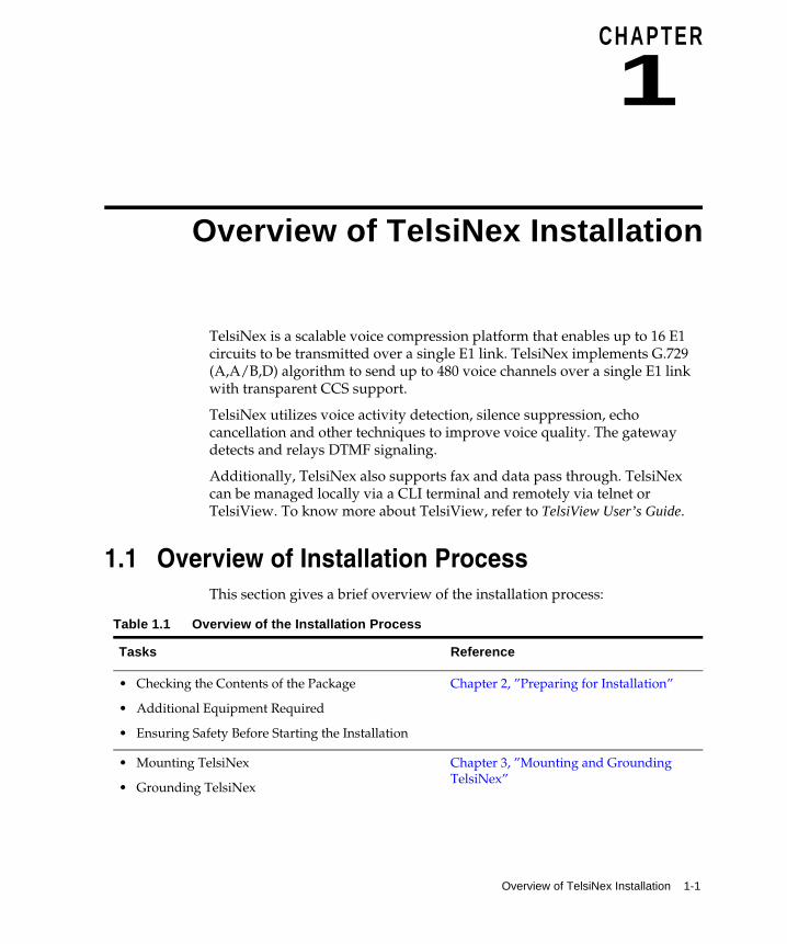
TelsiNex is a scalable voice compression platform that enables up to 16 E1 circuits to be transmitted over a single E1 link. TelsiNex implements G.729 (A,A/B,D) algorithm to send up to 480 voice channels over a single E1 link with transparent CCS support.
TelsiNex utilizes voice activity detection, silence suppression, echo cancellation and other techniques to improve voice quality. The gateway detects and relays DTMF signaling.
Additionally, TelsiNex also supports fax and data pass through. TelsiNex can be managed locally via a CLI terminal and remotely via telnet or TelsiView. To know more about TelsiView, refer to TelsiView User’s Guide.
1.1 Overview of Installation ProcessThis section gives a brief overview of the installation process:
Table 1.1 Overview of the Installation Process
Tasks Reference
• Checking the Contents of the Package
• Additional Equipment Required
• Ensuring Safety Before Starting the Installation
Chapter 2, ”Preparing for Installation”
• Mounting TelsiNex
• Grounding TelsiNex
Chapter 3, ”Mounting and Grounding TelsiNex”
1-2 TelsiNex Installation Guide
Overview of Installation Process
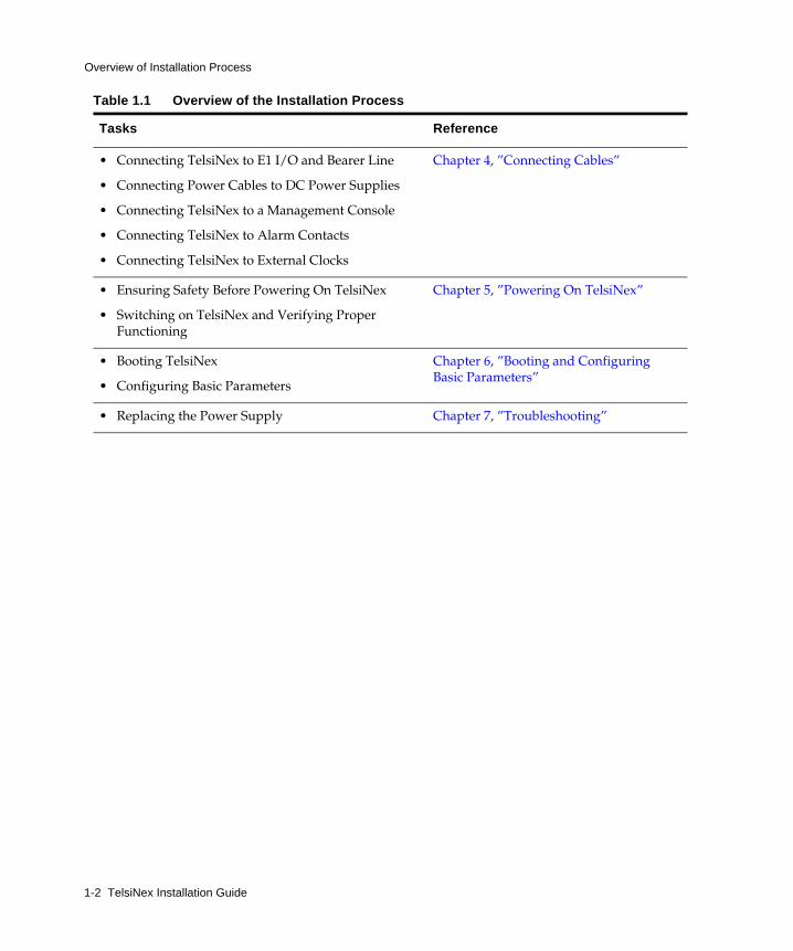
• Connecting TelsiNex to E1 I/O and Bearer Line
• Connecting Power Cables to DC Power Supplies
• Connecting TelsiNex to a Management Console
• Connecting TelsiNex to Alarm Contacts
• Connecting TelsiNex to External Clocks
Chapter 4, ”Connecting Cables”
• Ensuring Safety Before Powering On TelsiNex
• Switching on TelsiNex and Verifying Proper Functioning
Chapter 5, ”Powering On TelsiNex”
• Booting TelsiNex
• Configuring Basic Parameters
Chapter 6, ”Booting and Configuring Basic Parameters”
• Replacing the Power Supply Chapter 7, ”Troubleshooting”
Table 1.1 Overview of the Installation Process
Tasks Reference

Preparing for Installation 2-1
CHAPTER
2
Preparing for Installation
This chapter guides you through the process of checking the contents of the package and ensuring safety arrangements before you start the installation.
This chapter covers the following topics:
• Section 2.1, “Checking the Contents of the Package”
• Section 2.2, “Additional Equipment Required”
• Section 2.3, “Ensuring Safety Before Starting the Installation”
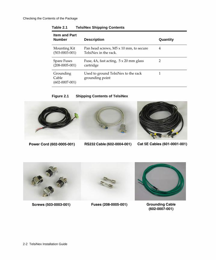
2.1 Checking the Contents of the PackageTable 2.1 lists the contents included in this package apart from the Telsinex system. If any item mentioned in the table is found missing or tampered, call Telsima Customer Support.
Table 2.1 TelsiNex Shipping Contents
Item and Part Number Description Quantity
DC power cord (602-0005-001)
Used to provide + or -48V power supply to TelsiNex. Two chords are provided for redundant power supply.
2
RS232 Cable (602-0004-001)
Used to connect the management console for O&M of TelsiNex. For more information on pin details, refer to Appendix A, “Modem Port Pinout”.
1
Cat 5E Cables (601-0001-001)
Used to connect trunks and bearer lines As per configuration
2-2 TelsiNex Installation Guide
Checking the Contents of the Package
Figure 2.1 Shipping Contents of TelsiNex
Mounting Kit (503-0003-001)
Pan head screws, M5 x 10 mm, to secure TelsiNex in the rack.
4
Spare Fuses (208-0005-001)
Fuse, 4A, fast acting, 5 x 20 mm glass cartridge
2
Grounding Cable (602-0007-001)
Used to ground TelsiNex to the rack grounding point
1
Table 2.1 TelsiNex Shipping Contents
Item and Part Number Description Quantity
Screws (503-0003-001) Fuses (208-0005-001)
Power Cord (602-0005-001) RS232 Cable (602-0004-001) Cat 5E Cables (601-0001-001)
Grounding Cable (602-0007-001)
Preparing for Installation 2-3
Additional Equipment Required
2.2 Additional Equipment RequiredEnsure that you have the following items:
• Screw driver with flat blade, width 5mm for rack mounting
• Screw driver star with head size 0
• Side cutting pliers of medium size
• RJ-45 crimping tool, standard
• Wire stripper
• Crafts-man blade
• Screw driver flat with 2mm blade for electrical connections
• A computer with Windows XP installed
• M5 nut driver
2.3 Ensuring Safety Before Starting the InstallationBefore installing TelsiNex, ensure that E1 cables have been routed, secured, and wiring of networks is installed on the premises using standard cable-system practices. Also ensure that all the tools and additional equipment required for the installation are available.
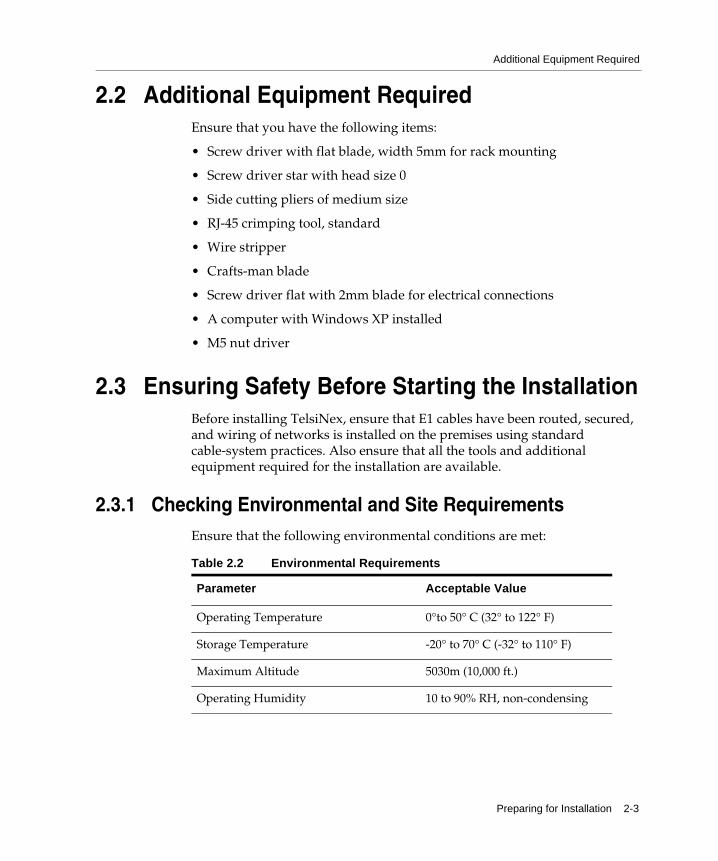
2.3.1 Checking Environmental and Site RequirementsEnsure that the following environmental conditions are met:
Parameter Acceptable Value
Operating Temperature 0°to 50° C (32° to 122° F)
Storage Temperature -20° to 70° C (-32° to 110° F)
Maximum Altitude 5030m (10,000 ft.)
Operating Humidity 10 to 90% RH, non-condensing
Table 2.2 Environmental Requirements

2-4 TelsiNex Installation Guide
Ensuring Safety Before Starting the Installation
2.3.2 Checking Electrical RequirementsEnsure that the following electrical requirements are met:
Parameter Acceptable Value
Input Voltage -40 to -60 V
Input Current 2 Amps Nominal @ -48 V DC
2.3.3 Checking Grounding ArrangementsYou must check if sufficient grounding arrangements are available at the installation site. For safety, it is important that the system is grounded properly.
You can do a continuity check with a multimeter between the ground terminal at the back of the chassis with the ground terminal on the rack. Ensure that isolated DC ground is available for grounding all equipment.
Refer to Section 3.2, “Grounding TelsiNex” for more information.
Table 2.3 Electrical Requirements

Mounting and Grounding TelsiNex 3-1
CHAPTER
3
Mounting and Grounding TelsiNex
This chapter guides you through the process of mounting the TelsiNex system on a 19-inch rack and then grounding the system.
This chapter covers the following topics:
• Section 3.1, “Mounting TelsiNex”
• Section 3.2, “Grounding TelsiNex”
3.1 Mounting TelsiNexTelsiNex comes with brackets mounted on the system. To mount TelsiNex, fix the brackets to the rack using the flat blade, 5 mm screw driver.
Figure 3.1 TelsiNex Mounted on a 19-inch Rack
3-2 TelsiNex Installation Guide
Grounding TelsiNex
3.2 Grounding TelsiNexYou need a grounding cable beforehand to ground TelsiNex. Once the TelsiNex chassis is mounted in a rack, connect the grounding cables.
The chassis ground connections require 12 AWG annealed solid copper conductors, bare or individually insulated with colored Polyvinyl chloride (PVC) listed by Underwriters Laboratories (refer to Telcordia document TA-TSY-000120).
Warning: This equipment must be grounded. Ensure that the chassis is connected to the earth ground during normal use. While installing the unit, always make the ground connection first.
All TelsiNex units must be grounded using the chassis grounding cable and lug provided. The grounding must be done to the nearest grounding bus bar or junction plate. Grounding must not be done to the steel racks or to the steel part of any other equipment. The grounding cable must be run to the nearest copper grounding busbar/ plate. Obtain and record the ground resistance of the site from the site in charge.
To connect a grounding cable:
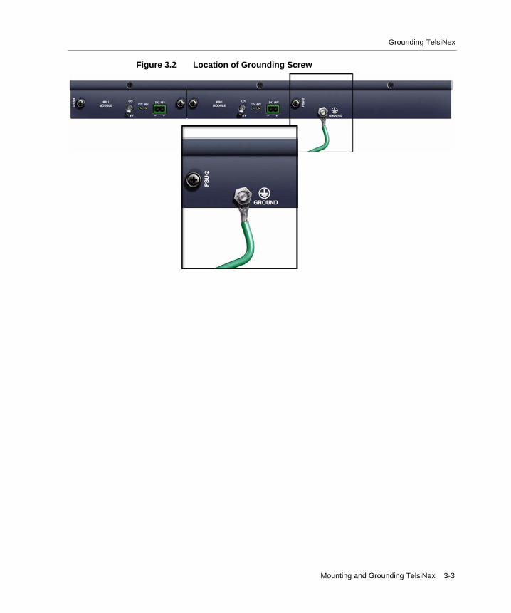
1. In the chassis, locate the grounding stud with two bolts.
2. Attach the other end of the ground cable to the rack, the grounding busbar, or any appropriate earth ground.
Note: The connection between TelsiNex and earth ground point must have an electrical resistance of less than one ohm.
Mounting and Grounding TelsiNex 3-3
Grounding TelsiNex
Figure 3.2 Location of Grounding Screw

3-4 TelsiNex Installation Guide
Grounding TelsiNex
Connecting Cables 4-1
CHAPTER
4
Connecting Cables
This chapter guides you through the process of connecting TelsiNex to the bearer and E1 I/O lines, power supplies, and a computer.
This chapter covers the following topics:
• Section 4.1, “Connecting TelsiNex to E1 I/O and Bearer Line”
• Section 4.2, “Connecting Power Cables to DC Power Supplies”
• Section 4.3, “Connecting TelsiNex to a Management Console”
• Section 4.4, “Connecting TelsiNex to Alarm Contacts”
• Section 4.5, “Connecting TelsiNex to External Clocks”
4.1 Connecting TelsiNex to E1 I/O and Bearer LineTo connect TelsiNex to E1 I/O and bearer lines:
1. Connect the E1 4/8/10/16 ports taken from DDF/MDF on to TelsiNex from E1 to E4/ E8/E10/E16 respectively with the help of RJ-45 cable provided in the accessories kit that is a part of this package. For more information on RJ-45 Pin Configuration, refer to Appendix A, “Pinouts”.
2. Connect the output E1 bearer line to the RJ-45 female connector B1. In case bearer line redundancy is required, use the E1 port B2. Figure 4.2 shows B1 to B4 ports. B3 and B4 are reserved for future use.TelsiNex automatically takes B1 or B2 as primary bearer if any one the bearer is connected. If both bearers are connected, then B1 will automatically become primary bearer and B2 will be the redundant bearer. Changeover between primary and redundant bearer is automatic.
4-2 TelsiNex Installation Guide
Connecting Power Cables to DC Power Supplies
3. Enable transparent channel in E1s for Signaling or Data as per your requirement in the particular channel. For more information, see Section 6.3.3, “Setting Transparent Channels”.
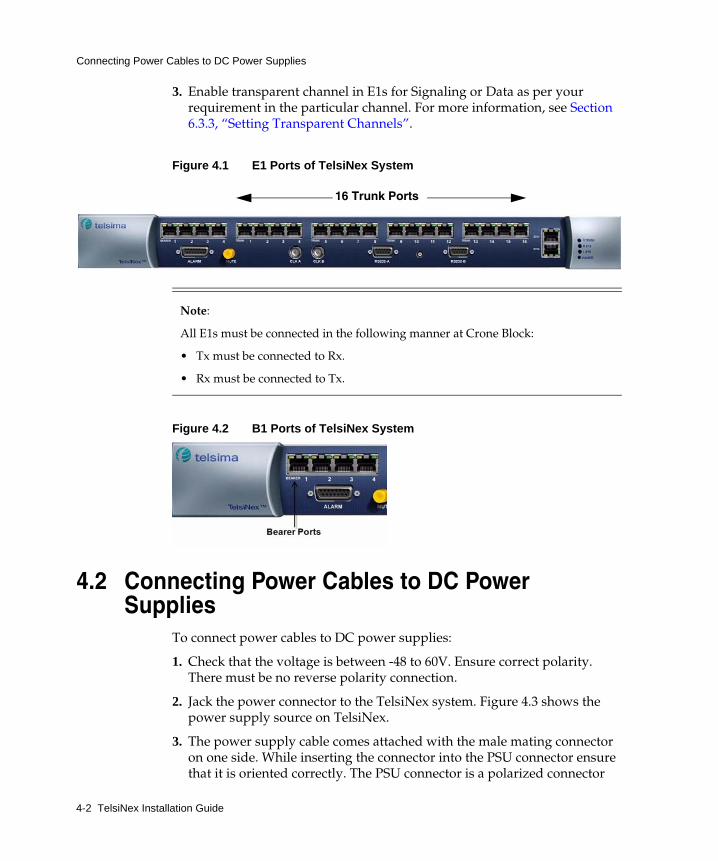
Figure 4.1 E1 Ports of TelsiNex System
Figure 4.2 B1 Ports of TelsiNex System
4.2 Connecting Power Cables to DC Power Supplies
To connect power cables to DC power supplies:
1. Check that the voltage is between -48 to 60V. Ensure correct polarity. There must be no reverse polarity connection.
2. Jack the power connector to the TelsiNex system. Figure 4.3 shows the power supply source on TelsiNex.
3. The power supply cable comes attached with the male mating connector on one side. While inserting the connector into the PSU connector ensure that it is oriented correctly. The PSU connector is a polarized connector
Note:
All E1s must be connected in the following manner at Crone Block:
• Tx must be connected to Rx.
• Rx must be connected to Tx.
16 Trunk Ports

Connecting Cables 4-3
Connecting TelsiNex to a Management Console
and can be inserted in one orientation only. Do not force the connector with a wrong orientation. Follow the polarity markings on the PSU face plate and insert the connector accordingly.
4. Connect the red color cable to +48 V power source and the black color cable to the -48V power source as shown in Figure 4.3.
5. Repeat steps 1 to 4 for the second power supply cable.
6. In case one of the connectors does not come attached or due to any reason you have removed the attached connector, follow the steps given below:
a) Strip approximately 8 mm (0.6 inch) of insulation off the ends of the power leads.
b) Loosen the screw on the rear side of the polarized connector and insert the red cable to slot one and black cable to slot two.
c) Tighten the screw and check whether the color coding of cable is followed properly.
Figure 4.3 Power Supply Socket on TelsiNex
4.3 Connecting TelsiNex to a Management ConsoleBefore turning on TelsiNex for the first time, connect a computer or a terminal server to the system. This section describes how to connect a computer or a terminal server to TelsiNex.

4-4 TelsiNex Installation Guide
Connecting TelsiNex to a Management Console
In all cases, you need an 8-pin, straight-through CAT-5 cable.
Note: By default, TelsiNex Management Console interfaces support a flow control setting of none. HyperTerminal has default flow control setting of hardware. If you disconnect a console cable from TelsiNex that is connected to a computer using HyperTerminal with flow control not set to none, the console interface may get stuck waiting for flow control to be turned on.
To prevent this issue, change the default flow control value to none on HyperTerminal before you connect the console cable to TelsiNex. Before you disconnect the cable, logout of the console session and disconnect the HyperTerminal session.
4.3.1 Connecting TelsiNex to a ComputerYou can connect TelsiNex to a computer through console port or ethernet port. Connectivity through the console port provides access to the CLI, whereas connectivity through the ethernet port provides access to the GUI-based NMS, TelsiView.
4.3.1.1 Connecting a Computer Through RS232-A Port
Figure 4.4 shows the RS232-A console port.
Figure 4.4 Console Port of TelsiNex
To connect a computer through the console port:
1. Ensure that a terminal emulation program is installed on the computer. For example, Hyperterminal or Tera Term.
2. Start the terminal emulation program.

Connecting Cables 4-5
Connecting TelsiNex to a Management Console
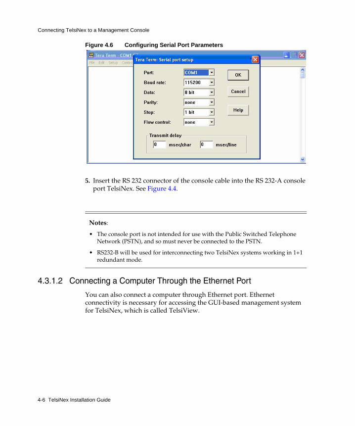
3. Configure the computer console communication data port using the following parameters:
4. Configure the port through the terminal emulation program or the computer control panel, using the instructions provided along with the computer.
Figure 4.5 Terra Term Serial Port Setup
Table 4.1 Console Port Parameters and Values
Parameter Value
Baud rate 115200
Data bits 8
Stop bits 1
Flow control None
Parity None
Emulation VT100
Notes:
4-6 TelsiNex Installation Guide
Connecting TelsiNex to a Management Console
Figure 4.6 Configuring Serial Port Parameters
5. Insert the RS 232 connector of the console cable into the RS 232-A console port TelsiNex. See Figure 4.4.
4.3.1.2 Connecting a Computer Through the Ethernet Port
You can also connect a computer through Ethernet port. Ethernet connectivity is necessary for accessing the GUI-based management system for TelsiNex, which is called TelsiView.
• The console port is not intended for use with the Public Switched Telephone Network (PSTN), and so must never be connected to the PSTN.
• RS232-B will be used for interconnecting two TelsiNex systems working in 1+1 redundant mode.
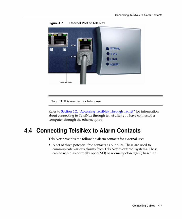
Note: ETH1 is reserved for future use.
Connecting Cables 4-7
Connecting TelsiNex to Alarm Contacts
Figure 4.7 Ethernet Port of TelsiNex
Refer to Section 6.2, “Accessing TelsiNex Through Telnet” for information about connecting to TelsiNex through telnet after you have connected a computer through the ethernet port.
4.4 Connecting TelsiNex to Alarm ContactsTelsiNex provides the following alarm contacts for external use:
• A set of three potential free contacts as out puts. These are used to communicate various alarms from TelsiNex to external systems. These can be wired as normally open(NO) or normally closed(NC) based on
4-8 TelsiNex Installation Guide
Connecting TelsiNex to External Clocks
customer requirements. The contacts are rated for maximum one amp current and 100V DC.These contacts are by default defined as:
- Minor alarms
- Urgent alarms
- Major alarms
• A set of two opto isolated inputs. These are used to sense any external world conditions and provide an alarm annunciation. These inputs can withstand up to a maximum of 6V DC and consume less than 10 mA.
These alarm signals are made available for external wiring through a DB15-connector on the front panel. Refer to Section A.3, “Alarm Port Pinout” for details on alarm pins.
4.5 Connecting TelsiNex to External ClocksTelsiNex has provisions to accept two external reference clocks named as Clk A and Clk B. These clocks can be network derived clocks and may be used for synchronising the Telsinex units to the local network. The clock inputs accept clock signals of 2. 048MHz ± 50 PPM as per ITUT G703 standards. The clock interface is through 75E coaxial cable connectors. The connectors used are of type Mini BNC from Tyco Amp. The cable side connector part number is Tyco- 1274563-1.

Powering On TelsiNex 5-1
CHAPTER
5
Powering On TelsiNex
This chapter helps you in taking appropriate safety measures before powering on TelsiNex and verifying proper functioning of the device.
This chapter covers the following topics:
• Section 5.1, “Ensuring Safety Before Powering On TelsiNex”
• Section 5.2, “Switching on TelsiNex and Verifying Proper Functioning”
• Section 5.3, “Testing TelsiNex as a Link”
Basic system configuration that is used for booting is stored in the flash file system. The system boots with the appropriate system image and an initial configuration is created with the information stored on the flash.
5.1 Ensuring Safety Before Powering On TelsiNexTo ensure safety before powering on TelsiNex, you must take the following precautions:
1. Check and ensure that the PSU toggle switches are in OFF position.
2. Check loading of the DC supply. As a thumb rule, DC supply must not be loaded more then 75 percent of its maximum capacity and it must have approximately 10 Amps of current available for TelsiNex.
3. Check that chassis earth is connected to the nearest ground point. Tug the wire to check that the connection is reliable.
4. Check for -48V on the power supply cable connector using a multimeter. Perform the check for both the power supply cables. The acceptable input DC voltage is between 40V and 70 V DC.
5-2 TelsiNex Installation Guide
Switching on TelsiNex and Verifying Proper Functioning
5.2 Switching on TelsiNex and Verifying Proper Functioning
Switch on TelsiNex by turning on both the PSUs one by one using the respective toggle switches.
Note: Allow 30 seconds of time between the switch on operation.
There are two LEDs related to power supply which indicate proper power supply:
• 48 V yellow LED glows if input of 48V is available.
• 12 V green LED glows if the power supply card is fine and giving an output of 12V to the MCC2.
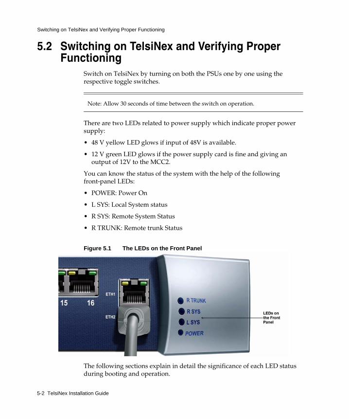
You can know the status of the system with the help of the following front-panel LEDs:
• POWER: Power On
• L SYS: Local System status
• R SYS: Remote System Status
• R TRUNK: Remote trunk Status
Figure 5.1 The LEDs on the Front Panel
The following sections explain in detail the significance of each LED status during booting and operation.
Powering On TelsiNex 5-3
Switching on TelsiNex and Verifying Proper Functioning
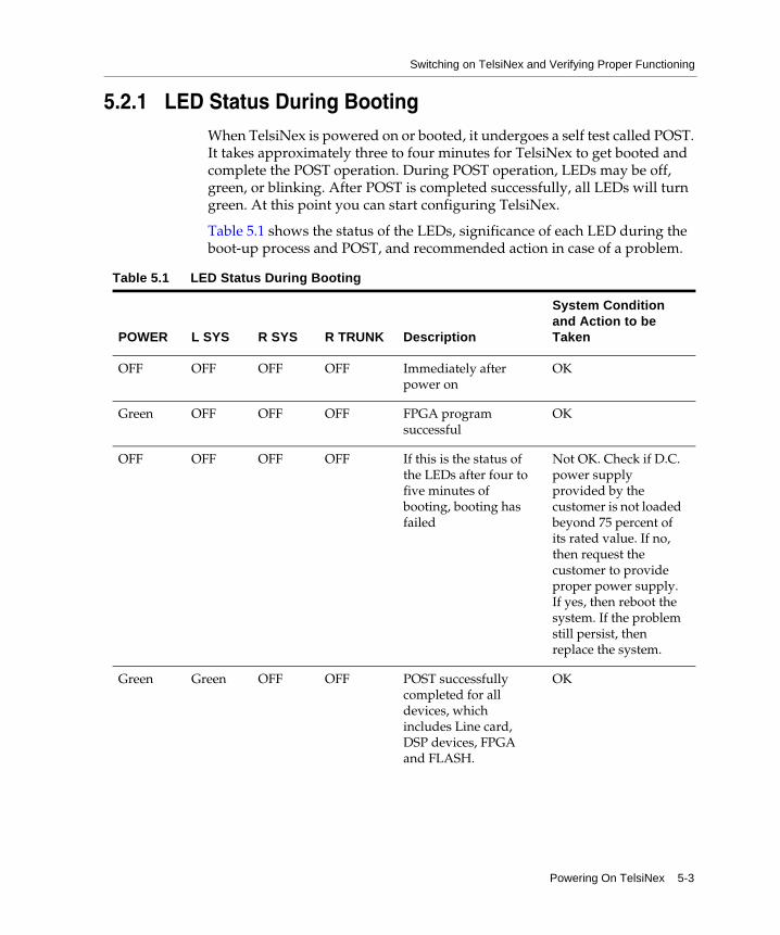
5.2.1 LED Status During BootingWhen TelsiNex is powered on or booted, it undergoes a self test called POST. It takes approximately three to four minutes for TelsiNex to get booted and complete the POST operation. During POST operation, LEDs may be off, green, or blinking. After POST is completed successfully, all LEDs will turn green. At this point you can start configuring TelsiNex.
Table 5.1 shows the status of the LEDs, significance of each LED during the boot-up process and POST, and recommended action in case of a problem.
Table 5.1 LED Status During Booting
POWER L SYS R SYS R TRUNK Description
System Condition and Action to be Taken
OFF OFF OFF OFF Immediately after power on
OK
Green OFF OFF OFF FPGA program successful
OK
OFF OFF OFF OFF If this is the status of the LEDs after four to five minutes of booting, booting has failed
Not OK. Check if D.C. power supply provided by the customer is not loaded beyond 75 percent of its rated value. If no, then request the customer to provide proper power supply. If yes, then reboot the system. If the problem still persist, then replace the system.
Green Green OFF OFF POST successfully completed for all devices, which includes Line card, DSP devices, FPGA and FLASH.
OK
5-4 TelsiNex Installation Guide
Switching on TelsiNex and Verifying Proper Functioning
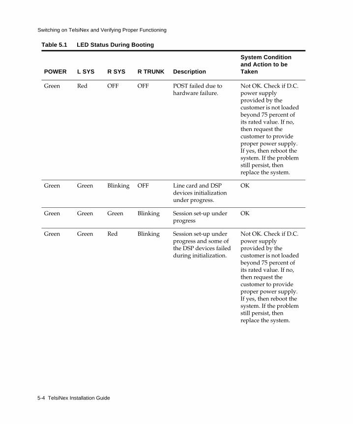
Green Red OFF OFF POST failed due to hardware failure.
Not OK. Check if D.C. power supply provided by the customer is not loaded beyond 75 percent of its rated value. If no, then request the customer to provide proper power supply. If yes, then reboot the system. If the problem still persist, then replace the system.
Green Green Blinking OFF Line card and DSP devices initialization under progress.
OK
Green Green Green Blinking Session set-up under progress
OK
Green Green Red Blinking Session set-up under progress and some of the DSP devices failed during initialization.
Not OK. Check if D.C. power supply provided by the customer is not loaded beyond 75 percent of its rated value. If no, then request the customer to provide proper power supply. If yes, then reboot the system. If the problem still persist, then replace the system.
Table 5.1 LED Status During Booting
POWER L SYS R SYS R TRUNK Description
System Condition and Action to be Taken

Powering On TelsiNex 5-5
Switching on TelsiNex and Verifying Proper Functioning
5.2.2 LED Status During OperationOnce the system is up and running, System LED status can be either GREEN or RED. Table 5.2, Table 5.3, Table 5.4, and Table 5.5 show the significance of the status of each LED during operation.
Table 5.2 Status of POWER LED: POWER ON During Operation
LED Status Description Action to be Taken
Green Power on
Red Power supply failure
Green Green Green Green System is UP and ready to handle traffic.
OK
Green Green Green Red Session set-up failed and system is not fully ready to handle traffic.
Not OK. Check if D.C. power supply provided by the customer is not loaded beyond 75 percent of its rated value. If no, then request the customer to provide proper power supply. If yes, then reboot the system. If the problem still persist, then replace the system.
Nil
Replace the power supply.
Table 5.1 LED Status During Booting
POWER L SYS R SYS R TRUNK Description
System Condition and Action to be Taken
5-6 TelsiNex Installation Guide
Switching on TelsiNex and Verifying Proper Functioning
.
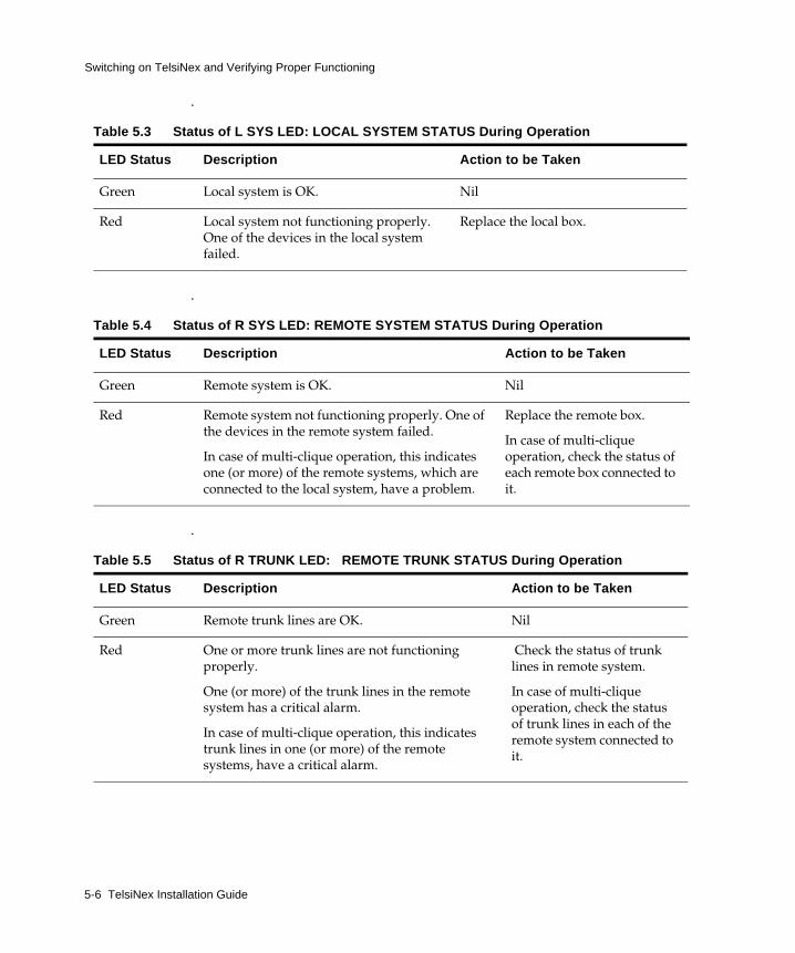
Table 5.3 Status of L SYS LED: LOCAL SYSTEM STATUS During Operation
LED Status Description Action to be Taken
Green Local system is OK.
Red Local system not functioning properly. One of the devices in the local system failed.
.
Table 5.4 Status of R SYS LED: REMOTE SYSTEM STATUS During Operation
LED Status Description Action to be Taken
Green Remote system is OK.
Red Remote system not functioning properly. One of the devices in the remote system failed.
In case of multi-clique operation, this indicates one (or more) of the remote systems, which are connected to the local system, have a problem.
.
Table 5.5 Status of R TRUNK LED: REMOTE TRUNK STATUS During Operation
LED Status Description Action to be Taken
Green Remote trunk lines are OK.
Red One or more trunk lines are not functioning properly.
One (or more) of the trunk lines in the remote system has a critical alarm.
In case of multi-clique operation, this indicates trunk lines in one (or more) of the remote systems, have a critical alarm.
Nil
Replace the local box.
Nil
Replace the remote box.
In case of multi-clique operation, check the status of each remote box connected to it.
Nil
Check the status of trunk lines in remote system.
In case of multi-clique operation, check the status of trunk lines in each of the remote system connected to it.
Powering On TelsiNex 5-7
Testing TelsiNex as a Link
5.3 Testing TelsiNex as a LinkAfter TelsiNex is mounted on the rack, all cables are connected, and the systems boots successfully, perform the checks explained in this section to ensure that TelsiNex is successfully connected to the network. If all the tests described here are positive, then TelsiNex is ready to transfer traffic over the network.
5.3.1 Checking Clock SynchronizationEnter the following command to check that clock is selected correctly at the local TelsiNex system. The output of the command shows the clock selected.
show dcme clock status
Enter the following command to check the clock selected at remote TelsiNex:
show dcme remote clock status
5.3.2 Checking the Line Report for BearerEnter the following command:
show hm lineperfreport
Nil report is OK.
5.3.3 Checking Line Report for Trunk E1sEnter the following command for first E1:
show hm lineperfreport 1
Enter the following command for second E1:
show hm lineperfreport 2
Similarly, check for all E1s. Nil report is OK.
5-8 TelsiNex Installation Guide
Testing TelsiNex as a Link
5.3.4 Checking End-to-End Connectivity of all E1sEnter the following command to check the connectivity of the first E1 in the particular link:
show interface alarm 1
Enter the following command to check the connectivity of the second E1 in the particular link:
show interface alarm 2
Similarly, check for all E1s. Nil report is OK.
5.3.5 Checking End-to-End Connectivity for BearerEnter the following command:
show interface bearer all
Nil report is OK.
5.3.6 Performing Loop Make and Break Test for Bearer on Both Ends
When you give the loop on the far end and enter the following command on local TelsiNex:
show interface alarm 1
The result of the command must show the resulting alarms as NIL.
5.3.7 Checking Fluctuation of MediaEnter the following command 15 to 20 times in a minute:
show hm lineperfreport
All the counts that are obtained from the command must not show an increasing value in the results.
Booting and Configuring Basic Parameters 6-1
CHAPTER
6
Booting and Configuring Basic Parameters
This chapter guides you through the booting sequence of TelsiNex and helps you to configure basic parameters of the system through the CLI.
This chapter covers the following topics:
• Section 6.1, “Booting TelsiNex”
• Section 6.3, “Configuring Basic Parameters”
6.1 Booting TelsiNexTelsiNex booting is successful if POST is successful after you power on TelsiNex. The user then starts the terminal emulation program (TeraTerm or Hyper Terminal) on the computer and connects it to RS-232A or by computer running Telnet connected to Ethernet Port - 1. It displays the default configuration of TelsiNex.
After you power on TelsiNex, start the terminal emulation program on the computer. Observe the booting sequence of TelsiNex on the computer. It displays the configuration of TelsiNex.
6.2 Accessing TelsiNex Through TelnetTo access TelsiNex through telnet:
1. Click Start, then select Run.
2. Enter the telnet command followed by the IP address of TelsiNex. The CLI window opens. You can also use a telnet client like Putty.
6-2 TelsiNex Installation Guide
Configuring Basic Parameters
3. Enter the default login name and password as admin.
6.3 Configuring Basic ParametersYou can configure the clock as internal, external, or derived based on the field requirement. However, irrespective of the type of clock set at one end, the remote TelsiNex must derive its clock from the bearer output of local TelsiNex.
You can also set the transparent channels according to the requirement and usage.
6.3.1 Setting the NameTo set the name for TelsiNex, use the following command:
set dcme serialnum <serialnum_string>
Here serialnum_string can be any 96 character box serial number. For example:
set dcme serialnum tel_north_region_32
6.3.2 Setting the ClockYou must set the local and remote clocks to trunk and bearer respectively. Configure the clock as internal, external or derived based on the field requirement. However, irrespective of the type of clock set at one end, the remote TelsiNex must derive its clock from the bearer output of local TelsiNex.
Booting and Configuring Basic Parameters 6-3
Configuring Basic Parameters
Setting the Local ClockTo set the main clock, use the following command:
set dcme clockselect <sys|ber|trk trunkId (1-16)>
You must always set the local clock to trunk, as shown in the following example;
set dcme clockselect trk 1
Setting the Remote ClockTo set the remote clock, use the following command:
set dcme remote clock <sys|ber|trk trunkId (1-16)>
You must always set the remote clock to bearer, as shown in the following example:
set dcme remote clock ber
6.3.3 Setting Transparent ChannelsSet the transparent channels according to the requirement and usage defined by the customer.
6-4 TelsiNex Installation Guide
Configuring Basic Parameters
To set the local transparent channel, use the following command:
set poolinfo map transparent <trunkId (1-16)> <trunkChannelId (1-31)>
To set the remote transparent channel, use the following command:
Note: You must enable or disable the transparent channels in the same order at both the local end and the remote end.
For example, assume that you enter the following commands at the local end:
Ensure that you set the remote channels in the same order:
set dcme remote transparentchannel <trunkId (1-16)> <trunkChannelId (1-31)>
6.3.4 Setting PCM ModeThe customer defines the PCM mode. It can be PCM30 or PCM31. Both TelsiNex systems in a link must have the same PCM mode setting.
To set pcmmode to PCM31, enter the following command:
set dcme pcmmode 1
To set pcmmode to PCM30, enter the following command
set dcme pcmmode 2
set poolinfo map transparent 1 1
set poolinfo map transparent 1 2
set dcme remote transparentchannel 1 1
set dcme remote transparent channel 1 2
Troubleshooting 7-1
CHAPTER
7
Troubleshooting
This chapter provides some troubleshooting tips.
7.1 Replacing the Power SupplyYou may need to replace the power supply if the power supply is defective. TelsiNex is equipped with dual supplies to provide redundancy. Both supplies are hot swappable and the system will continue to work normally with only one supply working.
A power supply defect is signalled by the front panel POWER LED, going red. The status of both power supply and failure of any one is reported on the NMS or terminal.
You can also ascertain the defective unit by observing the two LEDs on each of the power supply module. The failed supply module would have either one or none of the LEDs glowing. If the failure is at the supply source, then both the -48V (yellow) LED and the 12V(green) LED would be off. If the failure is at the power supply module, then the input -48V LED (yellow) would continue to glow while the 12V LED (green) would be off.
The two supplies can be plugged out or plugged in while the system is fully operational, without affecting the operational state. However, Telsima recommends that you perform the following steps while replacing power supplies:
1. Switch the ON/OFF toggle to OFF position to remove the supply. Note that this switch has a locking lever and cannot be switched ON/OFF inadvertently. To unlock the lever pull the lever. Then switch supply on or off.
2. Unscrew the two captive screws holding the supply in place.

7-2 TelsiNex Installation Guide
Replacing the Power Supply
3. Using the captive screws as holding point, pull out the supply.
4. Insert the replacement unit in to the empty slot. Ensure that it is switched off. Guide the unit smoothly on the PCB guides within the enclosure. You may have to apply a little more pressure to ensure that the supply connector connects properly.
5. Tighten the captive screws. Ensure that the supply face plate is seated flush with the enclosure.
6. Connect the -48V supply cord to the new PSU unit. Observe that the -48V DC available LED glows.
7. Pull the PSU toggle switch lever to On position. Observe that the 12V supply LED glows. The glowing LED indicates that the supply is on and the line is working.

Pinouts A-1
APPENDIX
A
Pinouts
This appendix describes the pinouts for the modem, 10/100 Ethernet, terminal ports, and alarm ports on the TelsiNex systems.
This appendix contains the following sections:
• Section A.1, “Modem Port Pinout”
• Section A.2, “RJ-E1 Port Pinout”
• Section A.3, “Alarm Port Pinout”
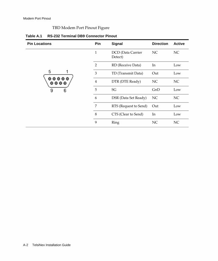
A.1 Modem Port PinoutTelsiNex includes a 9-pin, RJ-45 modem port. Table A.1 shows the pin locations and describes the pin signals.
A-2 TelsiNex Installation Guide
Modem Port Pinout
TBD Modem Port Pinout Figure
Table A.1 RS-232 Terminal DB9 Connector Pinout
Pin Locations Pin Signal Direction Active
1
2
3
4
5
6
7
8
9
DCD (Data Carrier Detect)
NC NC
RD (Receive Data) In Low
TD (Transmit Data) Out Low
DTR (DTE Ready) NC NC
SG GnD Low
DSR (Data Set Ready) NC NC
RTS (Request to Send) Out Low
CTS (Clear to Send) In Low
Ring NC NC
Pinouts A-3
RJ-E1 Port Pinout
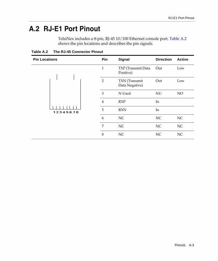
A.2 RJ-E1 Port PinoutTelsiNex includes a 8-pin, RJ-45 10/100 Ethernet console port. Table A.2 shows the pin locations and describes the pin signals.
Table A.2 The RJ-45 Connector Pinout
Pin Locations Pin Signal Direction Active
1 TXP (Transmit Data Positive)
Out Low
2 TXN (Transmit Data Negative)
Out Low
3 N Used NU NO
4 RXP In
5 RXN In
6 NC NC NC
7 NC NC NC
8 NC NC NC
A-4 TelsiNex Installation Guide
Alarm Port Pinout
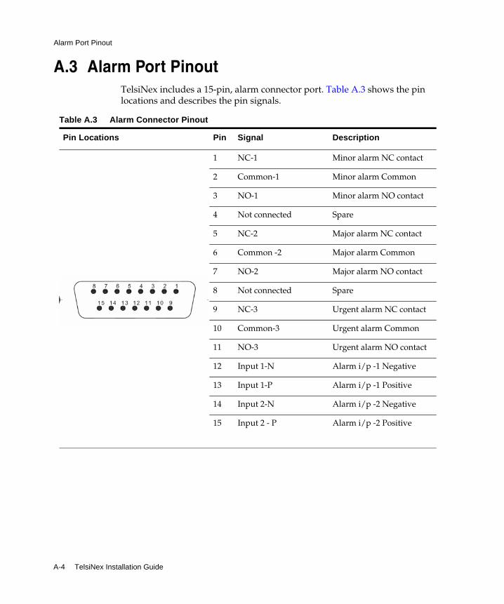
A.3 Alarm Port PinoutTelsiNex includes a 15-pin, alarm connector port. Table A.3 shows the pin locations and describes the pin signals.
Table A.3 Alarm Connector Pinout
Pin Locations Pin Signal Description
1 NC-1
2 Common-1
3 NO-1
4 Not connected
5 NC-2
6 Common -2
7 NO-2
8 Not connected
9 NC-3
10 Common-3
11 NO-3
12 Input 1-N
13 Input 1-P
14 Input 2-N
15 Input 2 - P
Minor alarm NC contact
Minor alarm Common
Minor alarm NO contact
Spare
Major alarm NC contact
Major alarm Common
Major alarm NO contact
Spare
Urgent alarm NC contact
Urgent alarm Common
Urgent alarm NO contact
Alarm i/p -1 Negative
Alarm i/p -1 Positive
Alarm i/p -2 Negative
Alarm i/p -2 Positive
i
Index
Aalarm contacts 4-7
Bbasic parameters
configuring 6-2setting clock 6-2setting name 6-2setting PCM mode 6-4setting transparent channels 6-3
bearer lineconnecting 4-1
Eequipment required 2-3external clocks 4-8
Ffront panel 5-2
Ggrounding 3-2
checking arrangements 2-4
Iinstallation
overview 1-1requirements
electrical 2-4environmental 2-3
LLED
booting status 5-3operation status 5-5
LEDs 5-2
Mmanagement console
connecting 4-3mounting 3-1
Ppackage contents 2-1port
console port 4-4ethernet port
connecting 4-6proper functioning
verifying 5-2

ii
Ssafety measures 2-3, 5-1
TTelsiNex
accessing through telnet 6-1booting 6-1setting clock 6-2setting name 6-2setting PCM mode 6-4setting transparent channels 6-3