television journal - world radio history
TRANSCRIPT

FM
ANTENNA
AUDIO
FM 107A 11.45 mc IF
IN
M 1078 ;~ 10.7 mc IF
FM ' FM 107C
ANTENNA 9.95 mc IF
4------- r----- FM FM 107D
ANTENNA -r 9.2 mc 1 F
------1
107 -FMC 101.2 mc OSC
FM OUTPUT:
A-89.75 mc B-º0.50 mc C-91.25 mc D-92.00 mc
PRESENT TV HEAD -END
ADD FM MULTIPLEX SERVICE TO YOUR
CATV SYSTEM
TV & FM to
TRUNK LINE
The Professional Television Journal
AP Television 1..12e4 Ave.
- -Les 3ö, calif.

I1it ....,,... ' 't[. i
TWICE THE
"CASCADE -ABILITY" OF ANY ALL -BAND AMPLIFIER
N E W
JE RIO LD
Model SCA-213 SUPER CASCADER AMPLIFIER
Two years in engineering, the new Jerrold all - band Super Cascader Amplifier is the ideal ampli- fier for expanding your system to the ultimate in all -band capabilities. The Model SCA-213 is de- signed for use in new or existing systems wher- ever maximum "cascade -ability" and reliability in an all -band trunk -line amplifier are prime requirements.
Provides 28 db of gain @ 216 mc, and output of 45 dbj* per channel for seven channels at a cross - modulation distortion of only 0.14%. The Super Cascader has been meticulously engineered to pro- vide long -life, trouble -free, economical service. Write for complete technical data.
0 dbj=1,000 microvolts across 75 ohms.
FEATURES MAXIMUM "CASCADE -ABILITY" EXTRA -WIDE BANDWIDTH (6-220 mc) PLUG-IN EQUALIZERS COMPENSATE FOR CABLE LOSSES
FREQUENCY RESPONSE FLAT WITHIN +1/2 db WITH EQUALIZATION VOLTAGE -STABILIZED TRANSFORMER PLUG-IN AGC (Use with Jerrold Model AGC-213) LOW NOISE FIGURE
HIGH OUTPUT CAPABILITY
J E R R O L D ELECTRONICS CORPORATION Community Systems Division Dept. IDS -227
MAIN OFFICE: WESTERN REGIONAL OFFICE: Philadelphia 32, Pa. BA 6-3456 1042 Terminal Way, San Carlos, California. LY 3-8273

v
Channel glop Commission's '52 Report/Order- Catastrophe?
FCC Commissioner Robert E. Lee, speaking before Institute of Radio Engineer's Annual Fellows Dinner, Tarrytown, New York on February 16, took to task the Com- mission's 1952 Report and Order, which ultimately established the present VHF -UHF 82 channel tele- vision system in the United States. Lee noted "... I did not participate in the Commission's Report and Order of 1952, but I would be no less critical than I am today were I to have been solely responsible for its errors. The ancillary trage- dies which have occurred since 1952 have caused me to believe that no single decision of the Commission has been so catastrophic.
"When the Commission spurned the advice of industry experts and adopted a television allocations plan intermixing VHF and UHF channel assignments in the same markets, it unwittingly preserved virtually the same television mo- nopoly that existed prior to the television freeze.
"Some 100 UHF television sta- tions came on the air and folded up in financial ruin after losses aggregating an amount which I would estimate to be $20 million. About 39 UHF stations are contin- uing in operation with annual op- erating losses which aggregate $2 million per year.
"... Basically, the situation has not been considerably improved. The fat cats in television continue to get fatter, the lean ones thinner and the public (is) deprived of competitive television. In 1957 we (the Commission) instituted an al- locations proceeding in Docket 11997 to determine the spectrum needs of various segments of the radio users-common carriers, in- dustrial licensees, local govern- ments and the whole gamut of those with needs for radio. It is one thing to listen to the needs of those potential users when there is some hope of satisfying these
CATV MATV Fringe TV ETV UHF -TV Associated
Industries' News
needs. However, it is quite frus- trating to have nothing to offer such hungry people.
"We at the Commission are being flooded with letters, resolutions, and petitions urging that we do not take away the only VHF serv- ice from the areas which we pro- pose to deintermix. Since these communications are, for the most part, identically worded, it is easy to see that the prosperous few are beating the bushes. So many of the public are being told that they are going to lose their only tele- vision service that I have been prompted to answer a few written personally to me (the UHF ogre!) I feel that if the situation is not corrected, the UHF stations now hanging on through dire financial straits will be bankrupted. As a result, the public's choice of pro- grams by and large could be re- duced from three (one VHF and two UHF stations) to one-a nice fat VHF station which can only carry one program at a time and hence one network at a time. Thus the listener could no longer have a choice between NBC, CBS, and ABC. Rather, the remaining station would have (in his power) the choice of which program to carry.
It is all apparent that it would choose the program most remuner- ative. How would the public be served by such a turn of events? I leave the answer to you."
DE -INTERMIXTURE DEADLINE SET BACK 3 MONTHS
The Commission, on March 7, an- nounced it was setting back until June 23 the previous deadline of March 23 for the filing reply com- ments in the proceedings currently underway to remove single VHF telecasters in 8 of the nation's larg- er cities.
All 8 areas have been scenes of bitter local debate and the cause of considerable congressional pres- sure placed on the Commission.
CATV OPERATOR WOULD APPLY FOR CHANNEL 15
William J. Calsam, operator of Oneonta Video and President of Craftsman Electronics (CATV products manufacturing firm), Oneonta, New York, has been suc- cessful in his bid to have channel 15, originally assigned to Rochester, N.Y., shifted to Oneonta. Calsam, in petitioning the Commission, stat- ed he intends to apply for channel 15 in Oneonta. Oneonta Video be- gan closed circuit local origination on a regular basis in June of 1961. Calsam is currently expanding his CATV operation to include micro- wave programming from New York City telecasters.
KATONA ELECTED VP AT CRAFTSMAN
Anthony S. Katona, formerly Administrative Assistant to Com- munity Systems Division Manager at Jerrold Electronics, Philadel- phia, has been added to the grow- ing team at Craftsman Electronics, Oneonta, New York. Katona is the new Vice President in charge of sales and engineering for Crafts- man. The Craftsman line is being expanded to include a complete line of amplifiers, distribution units, fittings, transformers, splitters and cable.
TELEVISION HORIZONS -THE PROFESSIONAL TELEVISION JOURNAL 1

APRIL 1962 VOLUME 3 NUMBER 4
TELEVISION HORIZONS PUBLISHED MONTHLY BY HORIZONS PUBLICATIONS
Post Office Box 1 557 Oklahoma City 1, Oklahoma
EDITORIAL Many of us tend to live within
a shell that not only 'protects' us from the outside world, but also shields us from the knowledge of others. For example, we recently were allowed to share in a tabula- tion of CATV systems in Great Britain and Ireland (these did not include the continent of Europe). we were surprised to see that by USA standards, nearly 2700 CATV systems exist in the U.K.! That's double the number in the United States, and it represents a land area smaller than the state of Texas.
Just as recently we spent nearly an hour on the telephone with a gentleman calling from Guatemala City, Guatemala, C. A. whose inter- est in CATV stemmed from his nation's limited number of broad- casting stations, and un -limited number of mountain shielded valley towns. In this case the local broad- casters have tentatively decided to go ahead with a program of CATV equipment installation as a joint owned and operated project. The stations, which derive little income from advertising, hope to be able to justify their existance by selling their signals on CATV to outlying areas. Not a new approach, but a novel one.
Finally, from Canada this month, a very interesting look into wired television in Canada by Mr. I. Swit- zer of Estevan, Saskatchewan. This month's first installment by Mr. Switzer details the reasons for Ca- nadian CATV acceptance. Next month's equally timely and interest- ing part two of this series will ap- proach Canadian CATV from an engineering standpoint. We believe you will be intrigued to learn what is takes to put CATV across out- side the USA, and the methods em- ployed by such capable operators as Switzer in providing the service.
TABLE OF CONTENTS
FEATURES
FM STEREO FOR CATV/MATV Profit or Problem? 4
FCC RELEASES PRELIMINARY DATA First Report on New York UHF Channel 31 Test 8
CANADIAN CATV OPERATORS SAY "Vive la Difference!" I. Switzer, Co -Ax TV Ltd., Estevan, Saskatchewan 10
REFLECTIONS IN CATV TRANSMISSION LINES Jacob Shekel, Spencer Kennedy Labs, Boston, Massachusetts 15
DEPARTMENTS
Late News of the Industry CHANNEL ONE 1
Foreign CATV Markets EDITORIAL 2
CATV Across the Atlantic OUR MAN IN EUROPE, Gordon J. King 17
News of the Wired TV World CABLE DROP 22
On Vacation This Month
FCC BRIEFS
DEPT. JJ
PR IN CATV
FIELD ENGINEERING
STAFF R. B. Cooper, Jr., W5KHT Publisher -Editor
Jim Kyle, K5JKX Managing Editor
Carlyne Silva Associate Editor
Les Forey Lon Cantor Charles Wigutow Mary Mitchell Vic Nicholson Contributing Editors
Gordon J. King "Our Man In Europe"
Jackie Johnson Business Manager Stanley M. Searle Art Director
Bonnie Fanter Circulation Manager
EDITORIAL OFFICES 4 NW 7th Street Oklahoma City, Oklahoma CEntral 2-1108
BUSINESS OFFICES 1518 -9th Street Modesto, California U.S.A. LAmbert 4-7395
ADVERTISING: Television Horizons accepts commercial display advertising from bona fide manufacturers of electronics equipment and apparatus dealing with the CATV, MATV, fringe -TV, ETV and rebroadcast TV industries. Advertising rate card and circulation data upon request.
CIRCULATION: Television Horizons is circulated through the mails and in person on the 5th of each month to an average of 7,500 readers in the CATV, MATV, TV servicing, fringe -TV, ETV and TV broadcast land rebroadcast) industries. Circulation is both paid and controlled. Detailed circulation breakdown, by reader occupation, is available upon request.
SUBSCRIPTION: Subscription rates in the United States and Canada $5.00 per year. Subscription includes the Annual Directory edition, issued every December. Single magazine copies $.50 each. Single Directory Editions $1.00 each. Subscription remittances should be made by bank money order or check. Two year subscription rate U.S.A. and Canada-$8.00. Subscriptions outside the U.S.A., Canada $6.00 per year.
TELEVISION HORIZONS (title registered U.S. Post Office) entered as second class postage material December 30, 1960. Second Class Postage Paid at Oklahoma City, Okla. All rights reserved. Address of publisher in Oklahoma City is 4 NW 7th Street.
2 TELEVISION HORIZONS-THE PROFESSIONAL TELEVISION JOURNAL
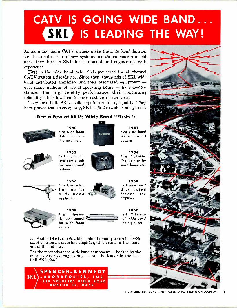
CATV IS GOING WIDE BAND... «ID IS LEADING THE WAY!
As more and more CATV owners make the wide band decision for the construction of new systems and the conversion of old ones, they turn to SKL for equipment and engineering with experience.
First in the wide band field, SKL pioneered the all -channel CATV system a decade ago. Since then, thousands of SKL wide band distributed amplifiers and their associated equipment - over many millions of actual operating hours - have demon- strated their high fidelity performance, their continuing reliability, their low maintenance cost year after year.
They have built SKL's solid reputation for top quality. They have proved that in every way, SKL is first in wide band systems.
Just a Few of SKL's Wide Band "Firsts":
1950 First wide band distributed main line amplifier.
1952 First automatic level control unit for wide band systems.
1956 First Chromatap line tap for wide band application.
1959 First "Therma- tic" gain control i for wide band systems.
1951 First wide band directional coupler.
1954 First Multivider line splitter for wide band use.
1958 First wide band distributed feeder line amplifier.
1960 First "Thermo - tic" wide band line equalizer.
. And in 1961, the first high gain, thermally controlled wide band distributed main line amplifier, which remains the stand- ard of the industry. For the most advanced wide band equipment - backed by the most experienced engineering - call the leader in the field. Call SKL first!
SPENCER -KENNEDY SKL LABORATORIES, I N C .
1320 SOLDIERS FIELD ROAD BOSTON 35, MASS.
TELEVISION HORIZONS -THE PROFESSIONAL TELEVISION JOURNAL 3
FM Stereo For CAT V/MATV
PROFIT OR PROBLEM? Like it or not, FM Stereo Multi-
plex is apparently here to stay. For many CATV systems, this new service offers the possibility of additional revenue-but it brings with it a number of new technical problems.
Even though off -the -air FM re- ception may be possible in your area, FM Stereo still offers revenue possibilities. Like color TV, FM Stereo requires a much stronger and cleaner signal at the set than is required by the older forms of transmission. CATV systems can provide the necessary signal.
Aside from the technical prob- lems-which have been worked out by at least one manufacturer-the only apparent drawback to a CATV system offering FM Stereo as an added service is the fact that some joint construction contracts with telephone systems prohibit the addition of FM service. All in- dications are that these restrictions are being eased, due primarily to the work of the NCTA pole line committees.
Introduction of FM Stereo to a CATV system also offers the pos- sibility of providing background music for business and professional subscribers, since much of the equipment used to provide FM Stereo to the trunk line is also capable of handling additional channels.
If this is done, the operator faces no extra technical problems but a few administrative dragons rear their heads. The most important is that arrangements must be made with ASCAP and BMI for payment of royalties for use of the music. These royalties usually amount to between 1/2 to 5'/2 percent of the total subscriber billing.
The necessity for royalty pay- ment is usually more than offset by the additional revenue obtainable from the background -music service. In fact, it's even possible (as a number of FM broadcasters have proved) to make a background - music service support all the rest of the operation.
Because of the problems encoun- tered in initial attempts to add FM Stereo to CATV systems, the NCTA asked several members for comments and suggestions. One of the most practical methods of add- ing FM Stereo to a system was that suggested by Kip Fletcher, opera- tions manager of Systems Manage- ment Company, Pottsville, Pa. A system similar to Fletcher's was in- dependently developed a year ear- lier and is being offered by CAS Manufacturing Co., Mineral Wells, Texas.
Before we examine the details of this system, let's review existing techniques for putting an FM chan- nel or two into a CATV system. Basically, three techniques are in use.
If your amplifier chain is an "all band" type, with bandpass from 54 to 220 mc., you probably merely pick up the existing FM channel and amplify it without processing. In this case-and this case only- you will have no problems with FM Stereo, since you do not proc- ess the signal in any way except to amplify it. A more common system is the
"low band plus" variety, which covers the range from 54 to 95 mc. This includes part of the FM band but not all. In this system, FM stations whose assigned channels fall within the system bandpass range are handled in the same manner as in an "all band" system, but FM stations whose frequencies are higher than 95 mc. must be treated in the manner used in a "low band only" system.
The "low band only" system, with a bandpass of 54 to 88 mc., includes no part of the regular FM band. In this system, FM stations must be moved from the 88-108 mc. band to a lower frequency. They may be put in place of a vacant TV channel, or in the 72-76 mc "guard band" between channels 4 and 5.
Two techniques are in use for moving the FM signal. Possibly
the most common method is to re- ceive the FM signal off -the -air with a conventional or special tuner, recover the audio signal, and then use this audio signal to modulate a low -power FM transmitter whose frequency is placed at the desired spot and whose output is fed into the amplifier chain along with the TV signals. This technique is not usable for FM Stereo!
Less commonly used is a double - conversion technique similar to that used to move a UHF or high - band TV signal to a low -band channel. In this technique, the FM signal is received off -the -air as be- fore but is not demodulated. In- stead, the intermediate -frequency signal of the FM tuner is then con- verted to the desired output fre- quency in a mixer stage, and the output applied to the CATV trunk line.
This double -conversion technique is the one recommended. Fletcher suggests that existing FM modula- tor equipment can be modified to accomplish this, by bypassing the audio stages in both the demodula- tor and modulator units.
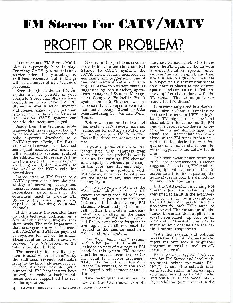
In the CAS system, incoming FM Stereo signals are picked up and converted to an IF in the neighbor- hood of 10.7 mc. by a crystal -con- trolled tuner. A separate tuner is necessary for each FM channel to be received. The outputs of all the tuners in use are then applied to a crystal -controlled up -converter which simultaneously converts as many as four channels to the de- sired output frequencies.
With this system, and optional accessories, the CATV operator can inject his own locally originated program material as well as off - the -air material.
For instance, a typical CAS sys- tem for FM Stereo and local pick- up might include two model FM - 107 (*) tuners (the asterisk indi- cates a letter suffix; in this example one tuner would be an "A" model and one a "B") ; one model M-107 (*) modulator (a "C" model in the
4 TELEVISION HORIZONS -THE PROFESSIONAL TELEVISION JOURNAL

`G -L i r7 @" TRANSMISSION LINE LOW-LOSS -<BROAD BAND - LIGHT WEIGHT
VHF Transmitter
VHF UHF
- 2,e67,779 - , ; 2,971,170
VHF -UHF Translator
Mobile Microwave Relay
Community TV
CONDUCTORS FOR G -LINE SYSTEMS
HIGH POWER
/ LAUNCHERS
OR RECEIVERS
RF Feeder Lines
Transmitters
Translators
Microwave Relays
Mobile Radios
MICROWAVE BY WIRE
alto
power
LOW POWER
LAUNCHERS
OR RECEIVERS
Closed Circuit (Community) TV
Home Reception &
Educational TV
Railroad Communication & Signaling Industrial TV
& Supervisory Systems Vehicular Communication & Control
UHF
MICROWAVE BY POLE LINE
UHF "No Booster"
Home Reception
VHF
"G-li- I ri @" SURFACE CONDUCTION INC., 1501 Broadway, New York 36, N. Y.
TELEVISION HORIZONS-THE PROFESSIONAL TELEVISION JOURNAL 5

example) ; and one model 107 -FMC up -converter.
With this installation, two sep- arate (Stereo) FM channels would be received. The FM -107 (A) tuner would convert its incoming FM signal to an intermediate frequen- cy of 11.45 mc; the (B) tuner's out- put would be at 10.7 mc; and the (C) modulator would convert in- coming audio signals from mikes, tapes, or discs to an FM signal at 9.95 mc. These three IF frequencies, applied to the 107 -FMC up -convert- er using a 84.45 mc. crystal, would produce three output frequencies at 73, 73.75, and 74.5-all within the guard band between channels 4 and 5.
For a "low band plus" system, it would be better to put the FM Stereo signals into the lower half of the regular FM band rather than into the guard band. For instance, a 101.2 mc. crystal will produce out- put signals at 89.75, 90.5, and 91.25 mc. In either case, the output of the 107 -FMC would be added to the output of the present TV head -end and fed to the trunk line.
With the double conversion sys- tem, many arrangements are pos- sible. In the CAS approach, for instance, you could use FM -45 (*) tuners to get 4.5 mc. output instead of 10.7 mc., and then apply this to a TV -M (*) unit to put an FM station onto a vacant TV channel. This would make FM available to subscribers who do not own FM
AMTFXNA
FM 1071 I1.15 net IF
AUDIO M 107
IÑ 10.7 n. If
M
,XT¡NN¡
FM EM 10I0 :i]
,.E If i
ANTENNA
101íM( 101.2 A.. 011
FM OUTPUT:
..E1.;5 w. E.E0.50 net
(,I.tS w.
0,0.00 w.
PRESENT TV HEAD ENO
TV . FM I.
11.0T.UNN
LINE
receivers-but this approach is not, as such, applicable to FM Stereo.
Fletcher suggests that an alter- native method for providing FM Stereo service might consist of using a stereo tuner at the head end, separating the stereo channels out, then putting the two stereo channels on the trunk at separate frequencies so that subscribers need not own FM Stereo equip- ment. This could be done in the CAS system by putting one stereo channel onto a vacant TV channel as described above, and by putting the other stereo channel into either the guard band or the low end of the regular FM band as described earlier for locally originated ma- terial. Then subscribers could re- ceive one channel of the stereo in- formation through their standard FM receiver, and the other through their TV set. This feature might provide added incentive for resi- dents to subscribe; whether the incentive would overbalance the
additional equipment investment required could be determined only by local evaluation of the situation.
The double -conversion technique is ideally suited to microwave links, and CAS produces a special line of equipment designed with this application in mind. At least two such installations are known to be in operation at the present time: one is a single -hop link at Brownwood, Texas, and the other is a pool arrangement in Wyoming in which several CATV operators have joined forces to operate a microwave link on a longer haul. Both of these installations are now carrying FM Stereo program material.
FM Stereo, even with the double - conversion system, will still pre- sent technical problems not present in conventional FM or TV signals.
Fletcher points out that the handling of FM Stereo signals will be substantially more delicate than that of the standard FM signal. There are two primary reasons: Drift in a tuned circuit can strip the 39-kc stereo -difference compo- nent from the FM Stereo signal, and non-linear distortion in any of the equipment (which would not affect a conventional FM signal) can result in cross -talk between the stereo channels.
Futhermore, Fletcher adds, since the phase relationship be- tween the components of the FM
(Continued - Page 21)
AMPLITUDE MODULATED SUPPRESSED CARRIER
SIDEBANDS (L -R)
PILOT 10%
19 23 38 KC KC KC
FREQUENCY
60 67 74 KC KC KC
6 TELEVISION HORIZONS -THE PROFESSIONAL TELEVISION JOURNAL

UHF TO VHF
VHF TO VHF
FM TO VHF
MUC
select the converter to do the job best from the world's only matched and integrated line
BLONDER -TONGUE UHF &VHF CONVERTER - AMPLIFIERS FOR MAN, CATV, CCIV, ETV
MODEL DESCRIPTION CAIN IMPEDANCE
INPUT OUTPUT FEATURES LIST
UC -2 UHF to VHF converter 6db to 10db 300 ohms 75 ohms
Built-in dual out - put mixing net- work.
165.00
MUC UHF to VHF converter 15db to 30db 300 ohms 75 ohms
Crystal controlled. Dual output mixing network.
387.50
CO -3 (not illus.)
UHF to VHF converter 1db to 5db 75 ohms 75 ohms Crystal controlled.
UHF pre -amp 558.00
UNIVERTER (not illus.)
VHF to VHF converter - 75 ohms 75 ohms
res external external power supply
143.25
MLC Lo to Lo VHF
converter 20db to 40db 75 ohms 75 ohms Crystal controlled. Dual output mixing network.
400.00
MVC HI to Lo VHF
converter 33db 75 ohms 75 ohms Crystal controlled. Dual output mixing network.
400.00
CO -2 (not illus.)
VHF & sub channel converter
up to 20db 75 ohms 75 ohms Crystal controlled. (FM to VHF avail- able, list 615.00.)
403.00
Today, contact your Blonder -Tongue distributor. Write for Free 28 page planning and installation manual. Free layout service. Also, engi- neering service available at cost.
engmeeretl and manufactured by
BLONDER TONGUE Canadian Div.: Benco Television Assoc.. Toronto. Export: Rocke Int'1. Corp.. N. Y. 16, N. Y: CABLES:ARLAB aubnpst,N..anr.n.r. home TV accessories UHF converters master TV systems closed circuit TV systems
TELEVISION HORIZONS-THE PROFESSIONAL TELEVISION JOURNAL 7

FCC RELEASES PRELIMINARY DATA .. .
FIRST REPORT ON NEW YORK
ULTRA HIGH FREQUENCY
CHANNEL 31 TEST Is the old bugaboo of UHF television-the belief
that UHF offers inherently poor picture quality- about to be blasted forever from the scene?
According to the first preliminary data obtained in the New York City tests, where the FCC is spend- ing $2 million to get an accurate, unbiased com- parison of UHF and VHF picture quality, no signif- icant inherent difference exists.
Commission engineer George V. Waldo, in re- leasing the data, cautioned that the figures represent too small a sampling of the planned 5,000 locations to draw meaningful conclusions. "Another group of data may result in entirely different conclusions," said Waldo. "Analysis of the data in further detail will not provide significant results until a much larger number of measurements have been made."
However, during the first four months of the test the UHF signal on channel 31 provided picture quality almost equal to the high -band VHF signal (channel 7) used for comparison, and the channel 31 signal was only slightly behind the low -band channel 2 picture as well.
Specifically, 89 percent of the locations provided a "grade 1" picture, the best obtainable, from the UHF signal. The figure rose to 91 percent for channel 7 and to 94 percent for channel 2.
A "grade 2" picture, showing perceptible degra- dation but still having high picture quality, was obtainable at 97 percent of the locations on both channels 31 and 7. The percentage rose a point to 98 for channel 2. These figures, naturally, include all locations at which a grade 1 picture was available.
All the locations tested provided a picture qual- ity of grade 3 or better on the two VHF channels, but the percentage fell to 99 for the UHF channel. At the grade 4 level, all channels had the same 100 -percent mark. The grade 4 level is the typical "deep -fringe" picture quality.
UHF proved slightly more susceptible to ghost- ing than did either of the VHF channels, but the ghosts did not seem to be as severe. Channel 7 was most ghost -free, with 77 percent of the locations showing no ghosts at all. On channel 2, the figure dropped to 71 percent, and on UHF, to 69 percent.
However, 94 percent of all locations reported pictures with detectable but non -disturbing ghost- ing on both UHF and high -band VHF. The figure rose to 96 percent for low -band VHF. In no case did ghosts bring the picture quality below "grade 4" level on any channel.
These figures are all based on use of outdoor antennas on all channels. With indoor antennas, channel 31 fared just about the same as .channel 7
8 TELEVISION HORIZONS -THE PROFESSIONAL TELEVISION JOURNAL
and both were noticeably inferior to channel 2. Only 43 percent of the locations provided perfect pictures on either 31 or 7, while 49 percent reported perfect pictures on 2.
Grade 4 reception or better was reported at 94 percent of the locations on UHF, compared to 99 percent at channel 7 and 97 percent at channel 2. At one percent of the locations, no usable picture could be obtained indoors on UHF.
"There is a slight difference between VHF and UHF picture quality at the average location," said Waldo, "but this difference is not significant con- sidering the limited amount of sample measurements completed at this time."
Normalized field -strength readings outdoors showed a 6 -db loss at channel 31 compared to channel 2; the loss compared to channel 7 was only 4 db. In- door measurements, again normalized, showed 15 db
-I00 INFERIOR
INFERIOR UNUSABLE
DEEP - FRINGE INFERIOR DEEP - FRINGE
-90 FRINGE FRINGE DEEP - FRINGE
FRINGE
-80
-70 GOOD GOOD GOOD
-60
-50
PERFECT
-40 PERFECT PERFECT
2 7 31
INDOOR ANTENNAS
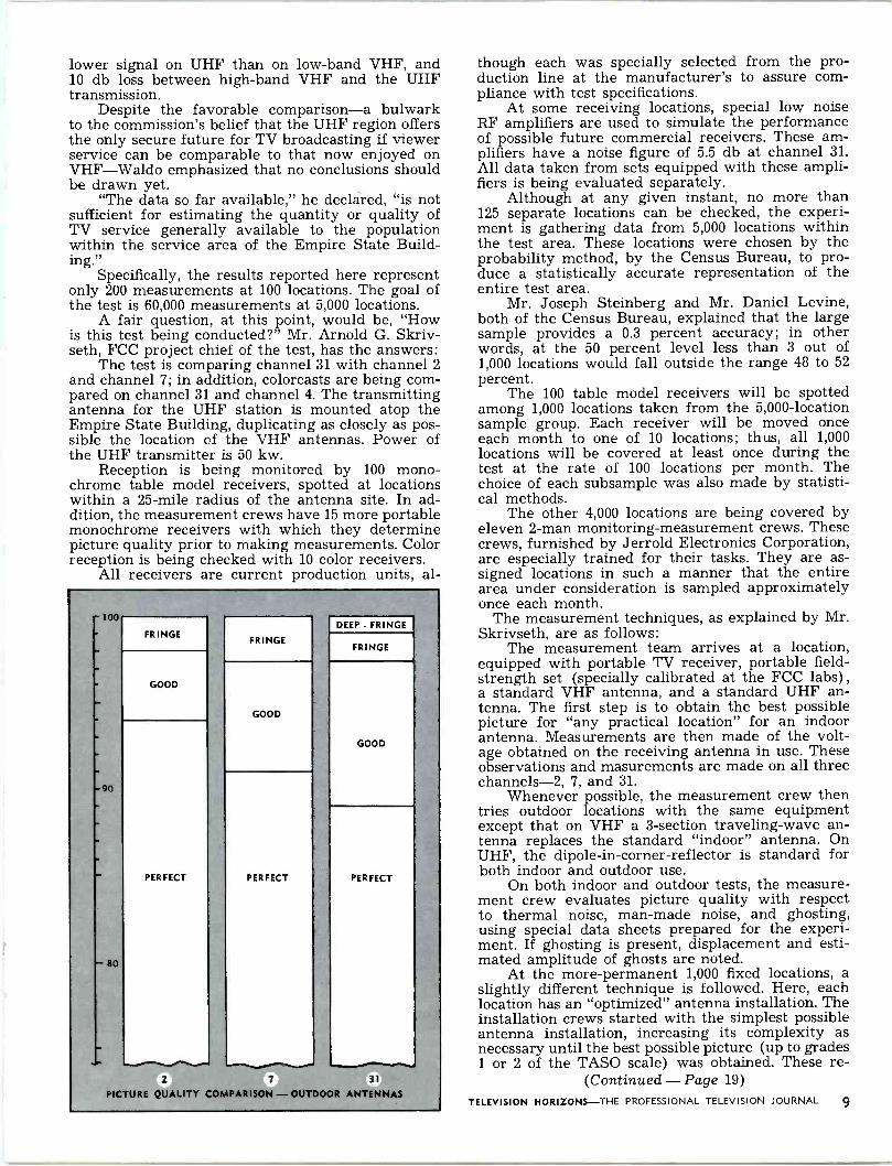
lower signal on UHF than on low -band VHF, and 10 db loss between high -band VHF and the UHF transmission.
Despite the favorable comparison-a bulwark to the commission's belief that the UHF region offers the only secure future for TV broadcasting if viewer service can be comparable to that now enjoyed on VHF-Waldo emphasized that no conclusions should be drawn yet.
"The data so far available," he declared, "is not sufficient for estimating the quantity or quality of TV service generally available to the population within the service area of the Empire State Build- ing."
Specifically, the results reported here represent only 200 measurements at 100 locations. The goal of the test is 60,000 measurements at 5,000 locations.
A fair question, at this point, would be, "How is this test being conducted?" Mr. Arnold G. Skriv- seth, FCC project chief of the test, has the answers:
The test is comparing channel 31 with channel 2 and channel 7; in addition, colorcasts are being com- pared on channel 31 and channel 4. The transmitting antenna for the UHF station is mounted atop the Empire State Building, duplicating as closely as pos- sible the location of the VHF antennas. Power of the UHF transmitter is 50 kw.
Reception is being monitored by 100 mono- chrome table model receivers, spotted at locations within a 25 -mile radius of the antenna site. In ad- dition, the measurement crews have 15 more portable monochrome receivers with which they determine picture quality prior to making measurements. Color reception is being checked with 10 color receivers.
All receivers are current production units, al-
-100 -
-
-
`
-90
-
- 80
PICTURE
FRINGE FRINGE
DEEP - FRINGE
FRINGE
GOOD
GOOD
GOOD
PERFECT
2
QUALITY
PERFECT PERFECT
COMPARISON
7 - OUTDOOR
31
ANTENNAS
though each was specially selected from the pro- duction line at the manufacturer's to assure com- pliance with test specifications.
At some receiving locations, special low noise RF amplifiers are used to simulate the performance of possible future commercial receivers. These am- plifiers have a noise figure of 5.5 db at channel 31. All data taken from sets equipped with these ampli- fiers is being evaluated separately.
Although at any given instant, no more than 125 separate locations can be checked, the experi- ment is gathering data from 5,000 locations within the test area. These locations were chosen by the probability method, by the Census Bureau, to pro- duce a statistically accurate representation of the entire test area.
Mr. Joseph Steinberg and Mr. Daniel Levine, both of the Census Bureau, explained that the large sample provides a 0.3 percent accuracy; in other words, at the 50 percent level less than 3 out of 1,000 locations would fall outside the range 48 to 52 percent.
The 100 table model receivers will be spotted among 1,000 locations taken from the 5,000 -location sample group. Each receiver will be moved once each month to one of 10 locations; thus, all 1,000 locations will be covered at least once during the test at the rate of 100 locations per month. The choice of each subsample was also made by statisti- cal methods.
The other 4,000 locations are being covered by eleven 2 -man monitoring -measurement crews. These crews, furnished by Jerrold Electronics Corporation, are especially trained for their tasks. They are as- signed locations in such a manner that the entire area under consideration is sampled approximately once each month.
The measurement techniques, as explained by Mr. Skrivseth, are as follows:
The measurement team arrives at a location, equipped with portable TV receiver, portable field - strength set (specially calibrated at the FCC labs) ,
a standard VHF antenna, and a standard UHF an- tenna. The first step is to obtain the best possible picture for "any practical location" for an indoor antenna. Measurements are then made of the volt- age obtained on the receiving antenna in use. These observations and masurements are made on all three channels -2, 7, and 31.
Whenever possible, the measurement crew then tries outdoor locations with the same equipment except that on VHF a 3 -section traveling -wave an- tenna replaces the standard "indoor" antenna. On UHF, the dipole -in -corner -reflector is standard for both indoor and outdoor use.
On both indoor and outdoor tests, the measure- ment crew evaluates picture quality with respect to thermal noise, man-made noise, and ghosting, using special data sheets prepared for the experi- ment. If ghosting is present, displacement and esti- mated amplitude of ghosts are noted.
At the more -permanent 1,000 fixed locations, a slightly different technique is followed. Here, each location has an "optimized" antenna installation. The installation crews started with the simplest possible antenna installation, increasing its complexity as necessary until the best possible picture (up to grades 1 or 2 of the TASO scale) was obtained. These re -
(Continued - Page 19)
TELEVISION HORIZONS -THE PROFESSIONAL TELEVISION JOURNAL 9

CANADIAN CATV OPERATORS SAY .. .
"V ive La Di f f erencer by
Mr. I. Switzer Co -Ax TV Ltd.
Estevan, Saskatchewan Canada
Americans living along the Canadian border and those travelling in Canada have no doubt noticed a distinct difference between television broadcasting in Canada and the United States. This difference in television broadcasting makes for a difference in community antenna systems. CATV operators in more than two hundred Canadian communities say "vive la difference". This difference makes com- munity antenna situations out of Canadian com- munities which would never support a system were they situated in the United States.
The Canadian Parliament, in passing the Broad- cast Act of 1958, decreed that Canadian broadcasting was to be developed along distinctive national lines and was to be guided by a Board of Broadcast Gov- ernors. The Broadcast Act says, in part, "The Board shall, for the purpose of ensuring the continued existence and efficient operation of a national broad- casting system and the provision of a varied and comprehensive service of a high standard that is basically Canadian in content and character, regu- late the establishment and operation of networks of broadcasting stations, the activities of public and private broadcasting stations in Canada and the re- lationship between them and provide for the final determination of all matters and questions in rela- tion thereto." Technical aspects of broadcasting are controlled by the federal Department of Transport (DOT) under the authority of the Radio Act. The functions of the DOT are generally analogous to those of the FCC, in that the DOT controls licensing of all kinds of radio transmitters and is also author- ized to license receivers. Under this authority the DOT licenses CATV systems as "Commercial Broad- cast Receiving Stations". The Board of Broadcast Governors, which controls broadcasting policy, has no jurisdiction over CATV.
The BBG has decided that Canadian television broadcasting shall develop along distinctive Cana- dian lines and serve the "national purpose" by broadcasting more Canadian programs and fewer
10 TELEVISION HORIZONS -THE PROFESSIONAL TELEVISION JOURNAL
American programs. Television broadcast licenses have been severely restricted in number in order to assure that those licensed should have the best possible chance to conform to the strict quotas on foreign programs and still pay their way. Beginning April 1st of this year Canadian TV stations must have at least 55% Canadian programming. Worded differently, this means that only 45% of program- ming on Canadian stations may be American pro- ductions. The BBG has been conscious for some time of the "vast wasteland" nature of American TV and has taken steps to create a television oasis (Canada) on this continent. The BBG has the author-
ity and apparently the courage to formulate and enforce programming regulations for Canadian net- works and stations that are, indeed, developing a distinctively different Canadian television broad- casting service.
Those Americans who have had the opportunity to notice that Canadian television is different from American television have probably also noticed that Canadians themselves are not basically different from Americans. Decades of living next door to the United States and being conditioned by American movies, magazines and radio has developed a kind of Canadian "camel", i.e. a large population that has a definite taste for the "vast wasteland" and is prepared to pay CATV service charges for the kind of antenna system needed to receive the U.S. pro- grams that the BBG quota keeps off the local Cana- dian stations.
Actually this situation has made more business for antenna manufacturers than for CATV operators. Most of the large population centres of Canada lie within direct reception range of U.S. television sta- tions, and these cities are veritable forests of tele- vision antenna all pointed "stateside". There are still many large Canadian centres beyond direct reception range or with serious terrain conditions affecting TV reception to give rise to a "professional" approach to CATV.
Canadian CATV opportunities lie principally in communities already being served by Canadian sta- tions but which are not able to receive U.S. stations. There are still some communities that do not have even Canadian broadcast service but these are rapidly being serviced by rebroadcast stations being operated as satellites of Canadian TV stations in larger communities. The BBG does not permit trans- lator rebroadcast within Canada of United States stations. A Canadian CATV operator providing

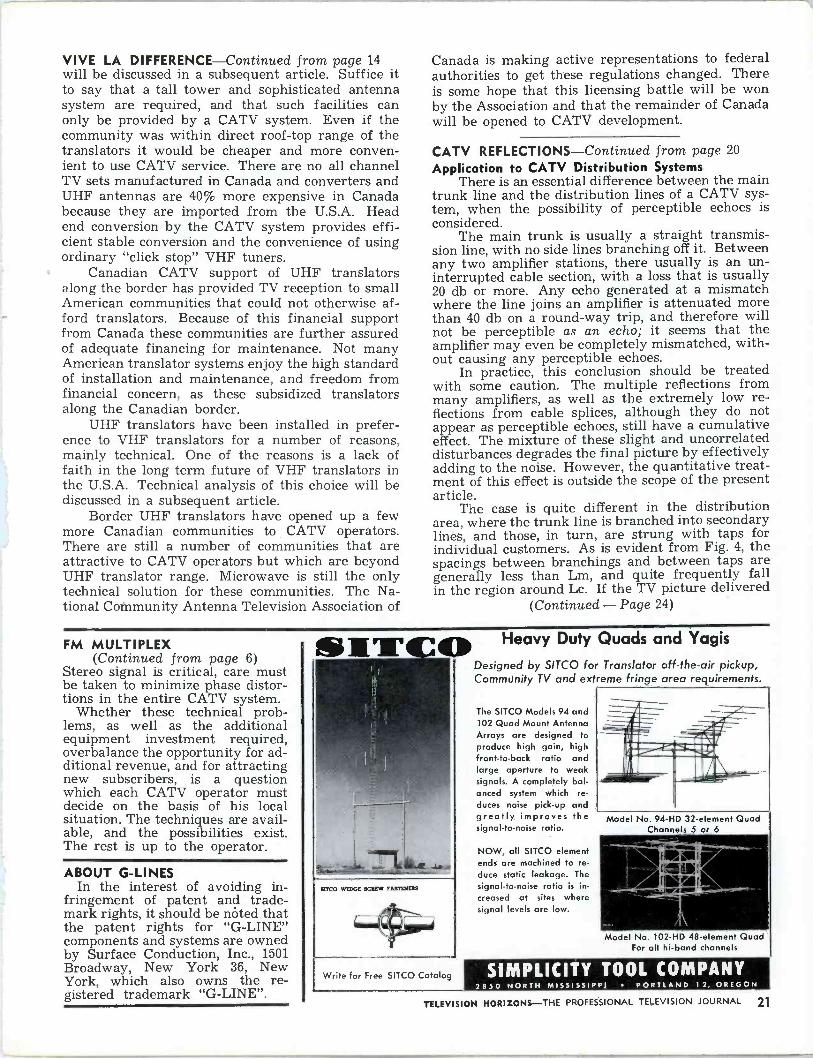
MARS ENGINEERING $$$$$$$$$$
ssssssssss SAVES YOU MONEY! Here are the facts on two money saving units from MARS. The new Mark 4 Multiple Output Amplifier and the well-known MAC 17 Translator will both save you money by giving outstanding performance and unequalled maintenance economy!
THE NEW MARS MARK 4 MULTIPLE OUTPUT AMPLIFIER MULTIPLY EXISTING COVERAGE AREA BY FOUR DESIGNED TO SUPPLY ONE WATT IN FOUR DIRECTIONS TO AN- TENNA SYSTEMS SERVING FOUR DISTINCTLY SEPARATE COMMU- NITIES. MAY BE DRIVEN BY EITHER /s OR 1 WATT VHF TRANSLATOR. FOUR 6360 OUTPUT TUBES, IN- DIVIDUAL MONITORING OF POWER OUTPUTS FULL VOLTAGE REGULATION, WEATHER-PROOF HOUSING $395.00
NHS mar VHF TRANSLATOR
ONLY THE MAC -17 OFFERS:
® ALL INDUSTRIAL TUBES
® OPTICAL IDENTIFIER LESS THAN 50 WATTS AC POWER DRAIN SINGLE UNIT CONSTRUCTION, SUPPLIED WITH WEATHER- PROOF HOUSING
1. 100% VOLTAGE REGULATED SMALLEST AND LIGHTEST TRANSLATOR
® $933.00 LIST, $700.00 NET
MID -AMERICA RELAY SYSTEMS, INC. 918 Tilford Street, Sturgis, S.D.
A SUBSIDIARY OF MIRATEL ELECTRONICS, INC.
Dealer, Distributor Inquiries Invited
TELEVISION HORIZONS -THE PROFESSIONAL TELEVISION JOURNAL 11

reception from U.S. stations is thus assured that no translators or satellites will spring up to duplicate the service that he is providing to subscribers. Be- cause of the strong demand for reception of U.S. stations a thriving CATV industry has grown up in Montreal, a metropolis of more than one million population. A city of such size in the U.S.A. could never be considered as a CATV opportunity. The Canadian government broadcast policy as adminis- tered by the BBG has created a kind of "financial insurance" for CATV investment in Canadian sys- tems that provide U.S. stations. Canadian CATV systems which cannot provide U.S. stations suffer from the prospect of rebroadcast stations or satel- lites, often financed by the Government, taking over their community functions. Canada is so firmly com- mitted to the policies expressed in the Broadcast Act that no change is in prospect in the foreseeable future. None of the political parties in Canada have promised any change in these policies. CATV, there- fore, has a secure long term future in Canada.
Canadian broadcast policies represent the view that television broadcasting and the spectrum space used is too precious and too powerful a force to be used only for entertainment. Entertainment func-
signal available for the community to be served. Needless to say this has severely restricted the ap- plication of microwave in Canadian CATV and has so far prevented establishment of CATV in many desirable Canadian communities, and is the main obstacle to an unlimited expansion of CATV in Canada. Canadian CATV systems must be based on technical systems acceptable to the licensing author- ity. This means direct cable connection (usually not exceeding 10 miles) to an off -air receiving site.
An editorial digression is appropriate at this point. DOT licensing regulations prevent establish- ment of CATV systems in a number of large Cana- dian cities which are so far from the U.S. border that they could be served only by microwave. Al- though the DOT has the authority to license private home TV receivers and to impose conditions on these licenses (such as prohibiting reception from the U.S.), no Canadian government has seen fit to commit political suicide by imposing such licensing on individual private TV sets in Canada. The Gov- ernment has seen fit to impose such restrictions only on those TV sets connected to CATV systems. Licen- sing a CATV system effectively licenses each TV set connected to that system. A CATV system should
Light areas on map show VHF broadcast coverage in Canada of US stations. These cover the largest population centres in Canada- Vancouver, Winnipeg, Southern Ontario. Note that Montreal is on the fringe of VHF coverage. This is reason for CATV growth there. Topography problems in Vancouver have been foundation for large number of CATV systems there.
tions fall back on CATV and closed circuit. CATV subscribers watch Canadian stations to be informed and instructed; they watch U.S. stations to be en- tertained.
The commercial development of a CATV situation requires not only a community with a television reception problem, but also a technical solution for that problem. Canadian CATV systems also need political solutions. There are many worthwhile Cana- dian CATV situations beyond the range of "ordinary" technical solutions. No tall tower, hill, or mountain will bring reception to a community 500 miles from the nearest U.S. TV station. Microwave is the only technical solution to this kind of TV problem, and this is where the political problem arises. The DOT, licensing authority for Canadian CATV systems, will not license CATV systems that use microwave relays to provide signal pickup to CATV systems in communities already served by Canadian broad- casting stations. This is interpreted to mean com- munities lying within the B contour of a Canadian station. Microwave cannot be used anywhere in Canada to relay U.S. stations unless this is the only
12 TELEVISION HORIZONS -THE PROFESSIONAL TELEVISION JOURNAL
enjoy all the rights and privileges that its sub- scribers have as individuals. This issue is presently being argued with the federal government on these grounds. Canadians in more remote cities should have the same privilege of receiving U.S. stations as their fellow citizens living right along the U.S. border and enjoying rabbit ear reception from the United States. If Canadian broadcast channels are reserved for Canadian programs then citizens should be permitted to establish private non -broadcast sys- tems for reception of U.S. programs. The main battle against direct reception of U.S. stations is already lost since 55% of the people in Canada live within direct reception range of the United States. Use of microwave to develop CATV systems further from the border would add only 5% of the population to the number already viewing U.S. stations. This 5% is a small part of the total population but represents a tremendous CATV business opportunity (900,000 people or 200,000 homes) .
The licensing restrictions which have restricted CATV development have, however, been of some benefit to CATV operators. The $25 license fee

IS YOUR
TRANSLATOR GROUP
Stilt &aching - io Mid ... FCC REQUIREMENTS?
HERE IS THE EASY WAY TO
"GET OVER THE LICENSING HUMP':.. and Complete Your VHF Translator Program!
zen eee telKe; I le re llekk* ei
Replace your old equipment with a brand new FCC type accepted TEPCO translator - The TE -2A. Only $795.00 for a complete 1 -watt unit, with power output meter!
The TEPCO TE -2A is completely self contained, and yet even at this most reasonable price, it con- tains all of the features normally found only in more expensive units. Ceramic coil forms, ceramic tube sockets, industrial type tubes and a big -husky power transformer. This unit is built to last and last and last. Outstanding performance is built into every TE -2A. It weighs 30 lbs. without cabinet! The weight alone tells you this is not "stripped down" construction.
NEW! VHF POWER OUTPUT METER FROM TEPCO. This unit measures peak video power, not the inaccurate figure that is often obtained when the aural and video power is combined. Write for full details today.
Other Quality TEPCO Products Available
TE -1B VHF Translator - Unsurpassed engineering excellence for the most exacting trans- lator requirements. TE -M Multiple Output Amplifier - For use in areas where FCC regulations will allow multiple output stages to cover more than one distinctly different communities.
1Pio For information on these and other Quality TEPCO Products-write to:
TEPCO CORPORATION P. 0. Box 2065 Rapid City, South Dakota Phone 343 7200
TELEVISION HORIZONS -THE PROFESSIONAL TELEVISION JOURNAL 13

places the CATV system under the protective mantle of federal jurisdiction. Canadian communities have no more say, through franchise, for example, over CATV operators than they have over the local TV or radio station. The DOT sets uniform conditions for licensing and operation and grants as many li- censes as there are competent applications, compe- tent meaning completion of simple application form and submission of the $25 fee. CATV, radio and television operate under federal jurisdiction and are therefore immune to the vagaries of local politics. One province does have legislation authorizing towns and villages to grant CATV franchises, but it is uni- versally opined that this legislation would be de- clared ultra vires if it were contested. Authority over CATV rests exclusively with the federal gov- ernment, but excepting the case of restriction of microwave the authority has served as a worthwhile protection rather than as oppressive regulation. The federal government has further served CATV by making it an offense against the criminal code to "steal" signals from a CATV system.
The effective CATV franchise rests with the agency, usually the telephone company, controlling pole attachment rights. Practically all the telephone companies in Canada have formulated CATV poli- cies which are considered satisfactory by CATV op- erators. Contracts with Canadian Bell are being used as precedents in conducting negotiations with Bell systems in the U.S.A. CATV franchise in Can- ada consists in having the initiative and resources
Three years ago 8)4NG0 pioneered the First
TRANSISTORIZED CATV SYSTEM Now BENCO Presents the Advanced "Model 3" Transistorized CATV System
AC POWERED - 20-50 Volts AC or DC TWO YEAR WARRANTY - On the New
"Model 3" Transistorized Amplifier.
GET A "PICTURE WITH A SNAP!"
Unique automatic gain control maintains signal levels over entire system 7 channels -5 low band and 2 sub -channels -22 Mc/s to 88 Mc/s 2000 feet amplifier spacing when low loss cable is used ONE transistorized power supply for several miles of cable T -AMP -3 transistorized amplifier is hermetically sealed
.8ENG0 TELEVISION ASSOCIATES LTD.
27 Taber Road, Rexdale, Ontario, CANADA
In U.S.A. Blonder-Tongue Laboratories, Inc. 9 Alling Street, Newark 2, N.J.
to go ahead. Still, the prospective CATV operator must have a licencable technical solution. Remem- ber, microwave is not allowed. CATV has been de- veloping in Canada since before 1953 and it is not surprising that by this time (early 1962) all the "easy" CATV situations have been taken up.
Cracking some of the remaining desirable CATV situations has required some ingenuity. Several U.S. TV stations have been established close to the border which derive most of their income from advertisers in Canada. These stations make their living by satisfying the same appetite that the CATV operator serves. The situation is analogous to situation along the Mexican border where Mexican licensed stations are serving U.S. border communities. BBG regula- tion cannot be extended to these border stations since they are outside Canada. The FCC has licensed these stations since they perform a useful broadcast func- tion within the United States. The Canadian gov- ernment cannot prohibit Canadians from receiving these border stations since doing so would create a "police state" as reprehensible as any behind the Iron Curtain. Subscribers to a CATV system cannot be denied reception rights that their non-CATV neighbours enjoy, so CATV systems, in such a case, must be, and are, licensed to receive U.S. border stations.
It soon became apparent that CATV could be developed in a few Canadian communities if there were more U.S. stations along the border. The num- ber of VHF border stations is limited by available VHF allocations and by the high cost of building and operating such stations. However, UHF trans- lators do not suffer from these problems. UHF translators are comparatively low in cost and there are plenty of channels available for their operation. They are licensed by the FCC as public broadcast stations and enjoy the same "diplomatic immunity" in Canada as their most costly and powerful VHF counterparts, and they provide the same desirable broadcast programs that the VHF broadcasters do.
UHF translators can be encouraged and subsi- dized by Canadian CATV operators so long as the spirit and letter of FCC regulations are scrupulously observed. Control of the translator must be held by licensees eligible under FCC regulations. The trans- lator must provide free broadcast service to an American community that needs it. Rebroadcast per- mission must of course be obtained from the origi- nating station. Function as a relay must be inci- dental to the translator's basic function as a broad- cast station. Since the subscribers of the Canadian CATV system receiving these translator broadcast signals is usually very much larger than the Ameri- can community concerned it is only fair that these subscribers, through the agency of the CATV sys- tem, should pay most of the costs.
Canadian CATV systems using such translator broadcast signals are from 30 to 60 miles from the border. At this range, the reception from low power translators presents some technical problems that
(Continued - Page 21)
14 TELEVISION HORIZONS -THE PROFESSIONAL TELEVISION JOURNAL

Mis -match? Ghosting? Garbled Audio?
civry REFLEcnONG by Jacob Shekel
Spencer -Kennedy Laboratories, Inc. 1320 Soldiers Field Rd., Boston 35, Mass.
The problem of reflections arises in any applica- tion where transmission lines are used. A uniform line - for example, a coaxial cable - can transmit signals equally well in both directions. However, any discontinuity in the line or any deviation from a uniform cross-section, results in coupling between the signals in both directions. A signal going one way is partially reflected at the discontinuity, and thus causes another signal that goes in the opposite direction.
The reflected signals may limit the performance of the system in various ways:
1. Obviously, the reflection of signal power back into the source means that less useful power is delivered to the load at the end of the line. This effect is most important when efficiency of power transmission is the prime factor, as is the case in a line that connects a transmitter to the an- tenna. 2. The signal that is reflected interferes with the original signal, so that the signal voltage along the line exhibits periodic maximum and minimum values. This is the phenomenon of standing waves, and the ratio of maximum to minimum voltage is the voltage standing wave ratio (VSWR). This effect is sometimes used to measure the ratio of the reflected and trans- mitted signals (reflection coefficient) .
3. The net voltage at a maximum point is high- er than would exist in the line if the same power were delivered with no reflections. Thus the maximum power handling capacity of the line is reduced. Because of the standing wave pat- tern, the net loss in the line is also increased, when compared to the reflection -less condition. 4. Of special interest in TV systems is the fact that the reflected signal may appear as an echo (or "ghost") on the TV picture. A reflected sig- nal may appear as a ghost on any receiver that is connected to the line at a point preceding the source of reflection; or the reflected signal may be re -reflected from another discontinuity and proceed along the line in the same direction as the main signal. In any case, the ghost will be delayed with respect to the main signal, and will appear on the screen as a fainter picture, dis- placed to the right of the main picture.
TV systems are especially sensitive to the effects described in the last paragraph, and they become objectionable in cases where the other effects are barely noticed. The subject of this article (and another article that will appear next month) is a detailed quantitative discussion of the effects of "ghosts" in TV distribution systems, and how it af- fects the specifications of system components.
Reflections Any deviation from a uniform cross-section of
the transmission line may cause reflections. The uniformity of the cable, of course, is controlled by the cable manufacturer, who does his best to keep the dimensions within necessary tolerances, and to keep the dielectric free from any irregularities. The splices and connectors are usually designed to form a transition which is as smooth and gradual as pos- sible.
But there are points on the transmission line where discontinuities cannot be avoided. The sys- tem includes amplifiers, equalizers, filters, line -taps, and other components, and at each junction of the cable with an instrument there has to be a discon- tinuity. Fortunately, it is possible to design the elements in such a way that, although the component does not look like the cross-section of a coaxial cable, it has very similar electrical properties, so that the reflection at the junction is minimized. The lower the reflection, the better is the component matched to the transmission line.
The reflection at any junction or discontinuity is measured by the reflection coefficient, which is the ratio of the voltage of the reflected signal to that of the incident signal. When this ratio is expressed as a positive number of decibels, it is called the return loss. Minimum Perceptible Echo
The question now arises, what is the maximum reflection coefficient (or, equivalently, the minimum return loss) to be allowed on a transmission line, that will not appear as a disturbing echo on the TV screen?
Since the judgment of picture quality is a sub- jective affair, the question does not have a unique answer. Many experiments were conducted, by dif- ferent organizations, about subjective judgment of pictures degraded by echoes, and Fig. 1 shows a representative curve that is widely accepted as a standard. This curve is described as a "summary curve, taken as reasonably representative, smoothed from data covering pictures and engraved geometri- cal forms."(')
The curve shows the smallest echo which is just perceptible on the screen. Its amplitude is given rela- tive to that of the original signal, and it is a function of the delay between the picture signal and the echo. The curve can be described by three characteristic features:
1. No echo is perceptible on the screen, if its delay is less than 0.018 microseconds. This delay corresponds to a horizontal displacement which is about 1/3500 of the width of the picture, so it is well below the resolution of the TV picture. 2. As the delay increases, the amplitude of the
(1) P. Mertz, "Influence of echoes on TV transmission," Journal of the SMPTE, May, 1953, pp. 572-596.
TELEVISION HORIZONS-THE PROFESSIONAL TELEVISION JOURNAL 15

o
just -perceptible echo is inversely proportional to the delay; that is, if the delay is doubled, an echo will be perceptible, even if it is only half as strong (6 db down) .
3. Echoes smaller than 1% in voltage (-40 db relative to the signal), are not visible at any delay. The curve therefore gradually changes from the downward sloping line towards the horizontal 40 db line.
Effects of Delay and Loss in a Cable A section of a CATV line, with the signal sup-
posedly going from left to right, is shown in Fig. 2. Suppose that the signal at point a is observed
on a TV set, and that there is some reflection at point b which is L ft. down the line. Assume that the signal at a is tapped by a simple non -directional tap -off, that responds equally to signals going in both directions (for example, a simple capacitor tap -off from the center conductor)
0 SI
b
r I
OBSERVATION
L ft.
FIG. 2
OBSERVING A REFLECTION THAT ORIGINATES AT A POINT FURTHER DOWN THE TRANSMISSION LINE
REFLECTION
The echo will be delayed, with respect to the signal, by the time it takes a signal to go from a to b and back to a. If y is the velocity of propagation of signals along the line, the delay T is related to the distance L by
L = vT/2. The echo/signal ratio at a is not the same as the
reflection coefficient at b, because of the losses along the path a -b. Let a be the loss of the cable in db/ unit length. The signal is attenuated °< L db before
10
30
40
.01 .02 .03 .05 .10 .20 .30 .50 2 3 5
FIG. 1
T MICROSECONDS
REPORTED TOLERANCES ON ECHO AMPLITUDE AS A FUNCTION OF ECHO DELAY (REPRODUCED FROM REFERENCE 1)
it hits the reflecting obstacle at b; the echo is again attenuated by oC L db on its way back to a. The echo at a, compared to the signal at the same point, is then 2 oc L db lower than the reflection coefficient at b. As a result, the tolerable echo at b is 2 oc L db larger than that indicated by Fig. 1.
Fig. 3 shows a typical plot of the tolerable return loss at b as a function of L. This plot is obtained from Fig. 1 by changing the horizontal scale from time T to distance L, according to the velocity of propagation, and by subtracting 2 oc L db from the maximum tolerable return loss at every point. The specific numerical values depend, of course, on the loss factor oc , but every curve will have three dis- tinctive features:
1. There is a maximum distance, Lm, at which echoes are perceptible. Any reflection, of what- ever magnitude, that occurs further than Lm from the point of observation, will be attenuated below perception. 2. There is a critical distance, Lc, at which the specification on permissible return loss is most severe. This is a region rather than a sharply defined distance, because the curve is quite flat at its minimum. 3. There is a critical value, Ec, for return loss; any return loss higher than Ec will not cause a perceptible echo, no matter at what distance from the point of observation the reflection occurs.
The actual values of these constants depend on the losses in the cable, and are therefore a function of frequency. Their meaning, as defined above, is strictly valid for single reflections only. The cumu- lative effect of multiple reflections will be briefly mentioned in the next section.
Fig. 4 shows the curves computed for RG -11/U coaxial cable, at the loss values corresponding to 54 mc and 216 mc.
(Continued - Page 20)
10 20 30
16 TELEVISION HORIZONS-THE PROFESSIONAL TELEVISION JOURNAL

GORDON J. KING Assoc. Brit. I.R.E.
Brixham, Devon, England
Almost all early British CATV systems had no network AGC. In fact, there are still many small systems operating quite well with up to a maximum of about eight repeaters in cascade from the begin- ning to remote terminations with only source AGC.
The Brixham system, for example, (population 10,000) with an overall trunk cable length approach- ing 11/2 miles, is devoid of network AGC. This is made possible by sitting and adjusting the repeaters to work, at least, 10 db below maximum inter -modu- lation -free output.
In this country it has been discovered that a sig- nal level tolerance of that kind of order caters for rises of signal due to temperature reduction of the cables and their consequent decrease in attenuation. But this applies only to small systems where the trunk loading is fully established at the launching. THERMISTOR CONTROL
There have been several attempts to equalise against thermal variations of cable attenuation by the use of thermistors in the repeaters themselves. The well-known coaxial relay equipment manufac- turer, Teleng Limited, exploited this idea many years ago. The thermistor was placed in a repeater where
it was influenced by changes in air temperature, and the resulting change of resistance of the thermistor was reflected in terms of bias change on the amplifier valves.
This was found to have limited value. The main snags were in obtaining the optimum temperature coefficient in relation to cable which was partly overhead and partly underground and in varying degrees of shade. MEAN LEVEL AGC
Another idea which was incorporated in the re- peaters was a so-called mean level AGC circuit. Here the sound or vision carrier of a specific channel was extracted at high impedance from the final stage of a repeater and applied to a separate amplifier, the signal output of which was rectified. The resulting direct voltage was smoothed and filtered and used as an AGC bias for the repeater amplifier valves.
This was reasonably successful, but had two ma- jor disadvantages. One was the high signal level that was required to produce a useable control bias, and the other was that in the event of failure of the car- rier selected for the control, the whole system went haywire. PILOT CARRIER AGC
Although this arrangement is probably very well known to my readers, it has been included for the sake of completeness. It is used mainly on the EMI
INPUT
CARRIERS: - Cl, C2, C3, C4, C5, AND C6.
SPLITTING PAD
Cl FILTER
C2 FILTER
C3 FILTER
C4 FILTER
C5 FILTER
C6 FILTER
CI AGC AMP
pi C2 AGC AMP
pi C3 AGC AMP
pi C4 AGC AMP
FIGURE 1
C5 AGC AMP
C6 AGC AMP
OUTPUT
COMBINING11> I
CARRIERS: - Cl, C2, C3, C4, C5, AND C6.
PAD
TELEVISION HORIZONS -THE PROFESSIONAL TELEVISION JOURNAL 17

CUT MAINTENANCE AND INSTALLATION COSTS .
UP TO 90 PERCENT!
The CAS Transistor CATV AMPLIFIER is the proven answer to your line amplifier problems.
CAS has put all the engineering know-how of 10 years CATV experience into the design of the TR -95a. Now you can put this knowledge to work
. . cutting your operating costs and saving dollars every day of the week!
TR -95a FEATURES
COMPLETELY TRANSISTORIZED WIDE BANDWIDTH (54 to 95 me at 30 db gain) CABLE POWERED TWO INPUTS ... TWO OUTPUTS, for line bridging or cascaded runs GAIN AND TILT TEMPERATURE COMPENSATED TILT ADJUSTS WITH GAIN CONTROL (gain control is a 20 db variable pad on input) WEATHER- PROOF, STRAND MOUNTING ENCLOSURE TABS CONTROL FLOW OF CURRENT IN AND OUT OF THE AMPLIFIER TRANSISTORIZED CIRCUIT CUTS OPERATIONAL EXPENSE MANY TIMES OVER ... ELIMINATES MUCH OF ELECTRIC POWER METER EXPENSE; 10-12 AMPLIFIERS CAN BE RUN OFF ONE METER! (Right now, small towns are operating systems on a Single Power Supply!)
Remember . . . CAS Manufactures ONLY Transistor CATV Systems!
It's our only business! And we make it our business to save You money. Write today for information on our complete line including Transistor Line Amplifiers, Bridging Amplifiers, Extenders; Matched Line Splitters (which pass voltage for line powered systems) .
C
You Can Count On CASI
MFG. CO"
P.O. Drawer B - Mineral Wells, Texas - FA 5-5124
ultra wideband CATV systems. A crystal controlled pilot carrier at a frequency towards the centre of the network passband is injected at source. This is passed by the network repeaters, but at certain repeaters the signal is extracted, amplified and rectified and used to provide an AGC bias. The bias is thus depend- ent on the network attenuation, and as this rises and falls due to thermal effects, so the gain of the repeat- ers featuring AGC changes to compensate.
There are very many systems in the UK using this kind of system, which is also popular in Europe generally, and it works very well indeed. An AGC repeater is used in the ratio of about every three or four "straight" repeaters. AGC PER CARRIER
Let's face it, a coaxial network is a compromise in matching. A high degree of cable match, imped- ance -wise, throughout a large system is virtually impossible. It is agreed that very good VSWR's can be achieved in local equipment, but overall on an ex- tended network this desirable condition quickly goes to the dogs. Odd things happen. After a mile or so of trunk, carriers tend to rise and fall in relation to each other. Intermodulation starts playing nasty tricks, and one then usually resorts to critical carrier level adjustments at source. The system becomes highly critical and lots of engineering time is burnt up in maintaining the delicate balance!
This undesirable state of affairs has been allevi- ated to quite a large extent here in the UK by break- ing the network up into service areas, each area being controlled by its own sub -station, as described in past reports.
The multiplicity of signals are filtered independ- ently at each sub -station and each carrier (or chan- nel) is applied to its own AGC amplifier. Each am- plifier also has a manual level control. This certainly makes relay life less frustrating, for now all the out- going carriers can be reset to the correct levels, and these are sure to be maintained by the AGC in spite of what may happen to the input levels.
When this arrangement is adopted, highly effec- tive filtering of the various carriers into their respec- tive amplifiers is essential. Also, each amplifier must have a response, at least, 50 db down at adjacent carrier frequencies, and there must be no spurious responses which would be likely to allow the passage of a carrier which is removed from the design pass - band of the amplifier.
Some systems have fallen down simply because these factors were not wholly satisfied. A six -carrier set-up is depicted in Fig. 1, and this may well repre- sent a three -channel TV system with three sound carriers and three vision carriers. All is very well provided each carrier is kept to its own little circuit. However, if, for example, a little of carrier one gets into carrier two circuit there are real fun and games. Let us suppose that carrier one carries a vision signal and that carrier two looks after the accompanying sound. Two Cl vision signals are thus going to enter the outgoing networks. There will be the correct signal via Cl circuit plus a very distorted signal, though at lower level (we hope), via circuit C2.
Apart from the response distortion resulting from a vision signal passing through a relatively nar- row band circuit, the delay characteristics between the two circuits differ considerably. This is displayed
(Continued-Page 24)
18 TELEVISION HORIZONS-THE PROFESSIONAL TELEVISION JOURNAL

UHF TEST-Continued from page 9
sults are to be evaluated separately to determine antenna complexity necessary.
How is the signal evaluated? Each evaluation for each channel is made
on a "Measurement Survey Data Sheet". The upper portion of the sheet identifies the location and equipment in use, as well as the date, channel, and time of the evaluation. Picture rating is made in a six -step scale, as follows:
Step 1 means "excellent". The definition is "The picture is of extremely high quality, as good as you could desire. Noise or multipath effects not percep- tible."
Step 2 is "fine". The picture is of high quality providing enjoyable viewing. Picture degradation is, however, perceptible.
Step 3 is "passable". The picture is of acceptable quality. Picture degradation, while present, is not objectionable.
Step 4 is "marginal". The picture is poor in qual- ity and "you wish you could improve it". Picture degradation is somewhat objectionable.
Step 5 means "inferior". The picture is very poor but you could watch it. Definitely objectionable pic- ture degradation is present.
The last step, 6, is "unusable". The picture is so bad that you could not watch it.
Ghosting is rated first by the number of ghosts present. Relative intensity is estimated as a percent- age of the main signal intensity. Negative ghosts are identified by circling the percentage figure. Presence or absence of smearing on the ghosts is checked.
Delay is measured in inches on the face of the screen. Since all sets in the survey use the same size screen, this information can be translated direct- ly into microseconds of delay. If the ghost leads the main signal, the delay is indicated as a "negative" figure.
Overall ghosting grade is rated on the same six - step scale used for general picture quality, but con- sidering only degradation due to ghosts.
Man-made noise is evaluated by switching to an unused channel and observing the effects of man- made noise on the raster in the absence of any signal. If adjacent or co -channel interference is visible, this is not considered "man-made noise".
Sound quality is rated on the same scale used for picture quality, substituting the word "sound" for "picture" and "listening" for "viewing" in the definitions of each step.
The lower portion of the form, dealing with measurements, is self-explanatory.
As mentioned earlier, one such sheet is filled out for each evaluation on each channel. This means that at each location, at least three such sheets are completed. If both indoor and outdoor measurements are made, six sheets are filled out. With 5,000 loca- tions in use and each location being sampled at least once a month for the full duration of the 12 -month test, this means that more than 150,000 separate evaluation sheets may be completed. These 150,000 sheets will contain the raw results of the test.
What's going to happen to the data after the test ends (sometime near the end of this year) ?
The exact processing techniques for test results have not yet been revealed. The results will "ulti- mately" be transferred to punch cards for possible
computer analysis, but Mr. Skrivseth explains that the actual mechanics of the transfer must await review (by data-processing specialists) of prelimi- nary results to determine the most efficient process- ing methods.
At the beginning of the test period, some seg- ments of the TV industry questioned the legitimacy of comparing UHF service with existing VHF opera- tions. They appeared to feel that the purpose of the NYC test was:to show "what can be done" with UHF.
E. W. Allen, chief engineer for the FCC, explains that this was not the purpose of the test. The real purpose, he continued, was to obtain a quantitative measure of the kind of service that can be rendered in New York City by reasonable installations. Since no absolute measure of just what is or is not satis- factory service exists, comparisons with VHF pro- vide the only adequate index of "satisfactory" ser- vice.
Mr. Skirvseth went into more detail. "Since no broadcast service is perfect," he explained, "it can be assumed that UHF will not be perfect. With this in mind, a reference is needed to determine what kind of service is adequate or tolerable for existing viewers.
"As a result," he continued, "the same kind of observations and measurements made on both VHF and UHF, at the same locations, determine how much better or how much worse UHF is than that service which the viewers now obtain.
"We are, of course," said Mr. Skirvseth, "open to some criticism that our installations will all be new installations. However, we are treating both bands alike and from existing information, such as that from TASO, deterioration of installations can be added as a separate factor."
Commissioners hope that results of this test, when available, will help answer the often -asked but never -scientifically -tested question, "Can UHF provide service equal to VHF?" Though the test is aimed primarily at the strong -signal area (within 25 miles of the transmitter) , recording installations at Princeton, N.J.; Philadelphia, Pa.; and Laurel, Md. are also monitoring the signal. The data ob- tained by these RCA -installed facilities will be added to the other propagation data which have been collected by the Commission.
"Test patterns may come through fine, but what about program material?" This question won't affect the NYC test. Though the programming consisted primarily of test patterns during the preliminary stage (while antenna installations were being made, and during an auxiliary circularly -polarized experi- ment), the programming during the bulk of the test consists of duplication of programs from six New York VHF stations as well as some independent pro- gramming originated by the City of New York. This provides a signal modulated with a picture which is representative of the type viewed by the public, and offers in addition the chance for direct com- parison of the same program on VHF and UHF. However, the direct -comparison feature is not an essential part of the experiment, and no special pains are being taken to assure the chance of comparison.
Despite the effort to remain impartial, the NYC test has found itself embroiled in politics. L. M.
(Continued - Page 24)
TELEVISION HORIZONS -THE PROFESSIONAL TELEVISION JOURNAL 19

CATV REFLECTIONS-Continued from page 16
J et z 0
Ec
- J Q z c.7
Vf
5 o - J W m -0 -12
z lo
z ü Ñ U W -J u - Lu oc 15
ej o I- Z O o. I- 2C Q
ìu
25 10 20 "t FT.
Lc L L, FIG. 3 TOLERANCE ON THE AMPLITUDE OF AN ECHO THAT ORIGINATES
AT A POINT L FT. DOWN THE LINE
L fl
/
54 Mc
loo
FIG. 4
TOLERANCE ON ECHO PRODUCED IN RG 11/U COAXIAL CABLE, AS A FUNCTION OF THE DISTANCE BETWEEN POINT OF
OBSERVATION AND SOURCE OF ECHO (Continued - Page 21)
30 50 200 300 500 1000 2000
20 TELEVISION HORIZONS -THE PROFESSIONAL TELEVISION JOURNAL
VIVE LA DIFFERENCE-Continued from page 14 will be discussed in a subsequent article. Suffice it to say that a tall tower and sophisticated antenna system are required, and that such facilities can only be provided by a CATV system. Even if the community was within direct roof -top range of the translators it would be cheaper and more conven- ient to use CATV service. There are no all channel TV sets manufactured in Canada and converters and UHF antennas are 40% more expensive in Canada because they are imported from the U.S.A. Head end conversion by the CATV system provides effi- cient stable conversion and the convenience of using ordinary "click stop" VHF tuners.
Canadian CATV support of UHF translators along the border has provided TV reception to small American communities that could not otherwise af- ford translators. Because of this financial support from Canada these communities are further assured of adequate financing for maintenance. Not many American translator systems enjoy the high standard of installation and maintenance, and freedom from financial concern, as these subsidized translators along the Canadian border.
UHF translators have been installed in prefer- ence to VHF translators for a number of reasons, mainly technical. One of the reasons is a lack of faith in the long term future of VHF translators in the U.S.A. Technical analysis of this choice will be discussed in a subsequent article.
Border UHF translators have opened up a few more Canadian communities to CATV operators. There are still a number of communities that are attractive to CATV operators but which are beyond UHF translator range. Microwave is still the only technical solution for these communities. The Na- tional Community Antenna Television Association of
Canada is making active representations to federal authorities to get these regulations changed. There is some hope that this licensing battle will be won by the Association and that the remainder of Canada will be opened to CATV development.
CATV REFLECTIONS-Continued from page 20
Application to CATV Distribution Systems There is an essential difference between the main
trunk line and the distribution lines of a CATV sys- tem, when the possibility of perceptible echoes is considered.
The main trunk is usually a straight transmis- sion line, with no side lines branching off it. Between any two amplifier stations, there usually is an un- interrupted cable section, with a loss that is usually 20 db or more. Any echo generated at a mismatch where the line joins an amplifier is attenuated more than 40 db on a round -way trip, and therefore will not be perceptible as an echo; it seems that the amplifier may even be completely mismatched, with- out causing any perceptible echoes.
In practice, this conclusion should be treated with some caution. The multiple reflections from many amplifiers, as well as the extremely low re- flections from cable splices, although they do not appear as perceptible echoes, still have a cumulative effect. The mixture of these slight and uncorrelated disturbances degrades the final picture by effectively adding to the noise. However, the quantitative treat- ment of this effect is outside the scope of the present article.
The case is quite different in the distribution area, where the trunk line is branched into secondary lines, and those, in turn, are strung with taps for individual customers. As is evident from Fig. 4, the spacings between branchings and between taps are generally less than Lm, and quite frequently fall in the region around Lc. If the TV picture delivered
(Continued - Page 24)
FM MULTIPLEX (Continued from page 6)
Stereo signal is critical, care must be taken to minimize phase distor- tions in the entire CATV system.
Whether these technical prob- lems, as well as the additional equipment investment required, overbalance the opportunity for ad- ditional revenue, and for attracting new subscribers, is a question which each CATV operator must decide on the basis of his local situation. The techniques are avail- able, and the possibilities exist. The rest is up to the operator.
ABOUT G -LINES In the interest of avoiding in-
fringement of patent and trade- mark rights, it should be nóted that the patent rights for "G -LINE" components and systems are owned by Surface Conduction, Inc., 1501 Broadway, New York 36, New York, which also owns the re- gistered trademark "G -LINE".
s r=.O Heavy Duty Quads and Yogis
Designed by SITCO for Translator off -the -air pickup, Community TV and extreme fringe area requirements.
Write for Free SITCO Catalog
The SITCO Models 94 and 102 Quad Mount Antenna Arrays are designed to produce high gain, high front -to -back ratio and large aperture to weak signals. A completely bal- anced system which re- duces noise pick-up and greatly improves the signal-to-noise ratio.
NOW, all SITCO element ends are machined to re- duce static leakage. The signal-to-noise ratio is in- creased at sites where signal levels are low.
. J - _ -- li íiì,'Ì
Ilil ovik
Model No. 94 -HD 32 -element Quad Channels 5 or 6
Model No. 102 -HD 48 -element Quad For all hi -band channels
SIMPLICITY TOOL COMPANY 2850 NORTH MISSISSIPPI PORTLAND 12, OREGON
TELEVISION HORIZONS-THE PROFESSIONAL TELEVISION JOURNAL 21
DANIELS TO ENTER PAY -TV?
The CATV industry is abuzz with speculation as to the future of channel 2, KTVR, Denver, since the announcement by Daniels &
Associates that Bill Daniels had purchased the property for an es- timated $2 million.
The former owner of KTVR, J. Elroy McCaw, had contracted with Teleglobe to use their system of pay -tv for a three year test.
EXPERIENCE PROVEN
BY OVER $16,000,000.00 IN SUCCESSFUL CATV SYSTEM
SALES .... IN JUST FOUR YEARS.
For Reliable System Sales, the Highest Return on Your Investment Dollar, Contact:
THE DANIELS TEAM
SYSTEM APPRAISALS
SYSTEM SALES
SYSTEM MANAGEMENT
NEGOTIATIONS
Daniels & Associates, Inc. THE DANIELS BLDG. - 2430 E. THIRD AVENUE
DENVER 6, COLO. - PH. DU 8-5888
In Canada: FRED T. METCALF 25 Crestwood Place, Guelph, Ontario
Telephone TA 2-2030
22 TELEVISION
Daniel's interest in CATV, and its kindredship (someday) with pay -tv, raises speculation that Dan- iels may be planning on -the -air tests with the new channel 2 prop- erty. AND ... DANIELS ONCE AGAIN!
Daniels & Associates announced their 51st transaction in three and one half years. The deal consisted of the sale of the Tel -I -Clear Sys- tem, Inc. CATV system, located in Laguna Beach, California. The CATV system was formerly head- ed by Lewis Lemieux, veteran California CATV operator, and serves approximately 2,300 sub- scribers. Purchaser of the property is Laguna Video, Inc., a corporation owned primarily by Narragonsett Capital Corporation of Providence, Rhode Island, headed by Royal Little, former President and Chair- man of the Board of Textron, Inc.
Daniels' subsidiary, System s Management Company, will oper- ate property under management contract. Mr. Lemieux has agreed to continue his services with the company for an indefinite period. NCTA BOARD MEETING REPORT
The NCTA Board of Directors, reporting the results of its recent Board of Directors' meet in Las Vegas, noted that President Bill Dalton has increased membership by 20% over the past 12 months. Dalton joined the group only one year ago.
An announcement following the meet noted "the Board reaffirmed NCTA's position that no need exists for federal regulation and called for careful scrutiny of legis- lation introduced in Washington that woud restrict economic growth of CATV." The Board also estab- lished a Microwave Study Group to provide information services to CATV systems and others interest- ed in the orderly development of microwave availability that would permit broader applications of CA TV in educational television, civil defense, emergency warning and weather services, and other broad areas of public interest.
"The Board also approved plans for NCTA's first management semi- nar scheduled for the University of Wisconsin in August, and plans for an institutional Industry film that would create wider public un- derstanding and acceptance of CATV."
The Board elected Lloyd Cal- houn, Hobbs, New Mexico, to fill the unexpired term of Norm Hen-
HORIZONS-THE PROFESSIONAL TELEVISION JOURNAL
dry, Prescott, Arizona. Hendry re- cently resigned when his CATV system was sold. PAY TV INTEREST GROWS
With Pay TV in Hartford, Con- necticut now working under a green light, numerous CATV in- dustry personalities have made themselves heard on pay tv in par- ticular and Hartford in general.
Among these was Irving B. Kahn, President of TelePrompTer Corporation. Kahn hailed the U.S. Court of Appeals decision, uphold- ing authorization of pay tv experi- ments in Hartford, as an important step toward broadening the scope of tv.
The court decision upheld the authority of the FCC to permit toll tv tests by Hartford Phone - vision Company, a subsidiary of RKO General, Inc. and the Zenith Radio Corporation.
Kahn, whose company plans to begin testing a "participation tv system" of its own, soon, said:
"All of us who believe that sub- scription television is not only in- evitable but desirable because it will improve the scope and quality of programming are pleased that this roadblock has been removed. It is in the public interest to test thoroughly the feasibility of all pay TV systems."
TelePrompTer's system of pay - tv, explained Kahn, is designed to supplement rather than replace ex- isting over the air free television. To this end, he said, TPT is in- vesting heavily in the development of a versatile system that embodies actual audience participation.

Introducing .. . VIKINGS ALL NEW STRIP COPPER SHIELD
"FOR THE HIGHEST ACHIEVEMENT IN QUALITY"
IMPROVED RADIATION CHARACTERISTICS
IMPROVED ATTENUATION
IMPROVED IMPEDENCE UNIFORMITY
SAME O.D. ON SINGLE & DOUBLE SHIELDED TYPE CABLES
USES STANDARD SIZE PRESSURE TAPS
WEIGHT REDUCTION BY 20 TO 40%
WITH NEW
STRIP COPPER SHIELD
LOW LOSS
FULLY FOAM DIELECTRIC -
VK11 SINGLE SHIELDED & SINGLE JACKETED VKD11 DOUBLE SHIELDED & SINGLE JACKETED
VK108 SINGLE SHIELDED & SINGLE JACKETED VKD108 DOUBLE SHIELDED & SINGLE JACKETED
VK100 SINGLE SHIELDED & SINGLE JACKETED
VKD100 DOUBLE SHIELDED & SINGLE JACKETED
ALL NEW SUPERIOR
STRIP BRAID
CO -AXIAL CABLE
SWEPT AND THOROUGHLY TESTED
NON -CONTAMINATING JACKET
TYPE O. D. (NOM.) Inner Cond.
O. D. (NOM.) Dielectric;
O. D. (NOM.) Shield
O. D. (NOM.) 2nd Shield
O. D. (NOM.) Jacket
Attenuation Channel
ft.) (db/100
Attenuation 13 Channel (db/100 ft.)
e Shipping Wei Ft Weight
Lbs/M Feet
VK11 .064 .285 .296 - .407 1.31 2.2 64
VKD 11 .064 .285 .296 .307 .407 1.31 2.2 73
VK108 .081 .373 .389 - .460 1.01 1.6 89
VKD 108 .081 .373 .389 .400 .460 1.01 1.6 101
VK100 .114 .525 .536 - .632 0.77 1.3 147
VKD100 .114 .525 .536 .547 .632 0.77 1.3 167
CALL US COLLECT FOR SPECIAL LOW QUANTITY PRICES ON ALL OUR ITEMS AND TO DISCUSS YOUR SPECIAL NEEDS
VIKING CABLE COMPANY
830 MONROE STREET HOBOKEN, NEW JERSEY
MANUFACTURERS OF COAXIAL CABLE AND PRODUCTS FOR THE COMMUNITY TV INDUSTRY
TELEVISION HORIZONS-THE PROFESSIONAL TELEVISION JOURNAL 23

CATV REFLECTIONS-Continued from page 21
to the customer is to be free of disturbing echoes, particular attention should be paid to the possible sources of reflections in the branchings, taps, ampli- fiers and other components in the distribution lines. This subject will be treated in detail next month.
UHF TEST-Continued from page 19
Sandwick, staff director of the Consumer Products division of the ETA, called attention to the test dur- ing testimony recently before the Senate Commerce Subcommittee on Communications. "It is not incon- ceivable," said Mr. Sandwick, "that UHF will be found impractical in New York."
And so the controversy goes on.
MAN IN EUROPE-Continued from page 18
on a picture tube as a nice solid signal at Cl plus an echo caused by the Cl signal arriving a little later (could be earlier) via circuit C2. The result is phase distortion of the first order, and this could well be aggravated by some of Cl vision signal getting into the combining pad through other circuits as well.
Phase distortion on sound does not matter much on our AM system, but could be troublesome later when we change over to FM.
A lot of work has been done to kill spurious AGC amplifier responses and to endow each amplifier with a very fast cutoff outside the passband without intro- ducing ringing, and a properly engineered system of the nature described has very much to commend it.
NEXT BEST THING TO THE WINEGARD ELECTRONIC POWERTRON
TV ANTENNA
NEW TRANSISTOR TV -FM
WINEGARD TENNA
BOOST
INSTALL IT ... FORGET IT !
ALL ELECTRIC, ALL -AC POWER SUPPLY costs less than 27c a
year to operate. Many exclusive features. No costly, nui- sance batteries!
Built-in two set coupler.
Exclusive Gain Control Switch
i
AC outlet on
power supply.
MOUNTS ON ANTENNA
19 DB GAIN! CUTS SNOW...BOOSTS SIGNAL! Now you can make any TV or FM antenna work better by magnifying signals with the new Winegard tran- sistor Tenna-Boost.
Tenna-Boost has up to 19 DB gain, no peaks and valleys. Ultra low noise. Linear frequency response. VSWR input better than 1.5:1 across all frequencies. Output VSWR 1.8:1 or better. This fine frequency response plus the very low VSWR make Tenna-Boost ex- cellent for color.
orized Electronic owe ron ntennas. 3 Models
to Choose From.
Winegard's exclusive input band- pass filter eliminates interference from citizen's band, Hams, garage door openers, etc. Only TV and FM signals are amplified.
All metal parts are anodized, irri- dized or stainless steel. Completely weather-proof, trouble -free. Install it .. forget it.
There's a big difference in antenna amplifiers! Ask your distributor or write for technical bulletin.
24 TELEVISION HORIZONS-THE PROFESSIONAL TELEVISION JOURNAL
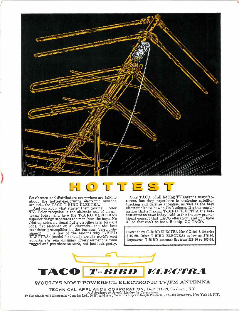
L -L 1 - Servicemen and distributors everywhere are talking about the hottest -performing electronic antenna around-the TACO T -BIRD ELECTRA.
And you know what started them talking ... color TV. Color reception is the ultimate test of an an- tenna today, and here the T -BIRD ELECTRA's superior design separates the men from the boys. No friction noise, no signal flutter, a rifle -sharp forward lobe, flat response on all channels-and the best transistor preamplifier in the business (Jerrold -de- signed) . a few of the reasons why T -BIRD ELECTRAs (model for model) are the world's most powerful electronic antennas. Every element is extra rugged and put there to work, not just look pretty.
Only TACO, of all leading TV antenna manufac- turers, has deep experience in designing satellite - tracking and defense antennas, as well as the best electronic know-how in the business. It's this combi- nation that's making T -BIRD ELECTRA the hot- test antenna news today. Add to this the new promo- tional concept that TACO offers you, and you have a line that can't be beat. Hot tip: GO TACO.
Shown above :T -BIRD ELECTRA Model G-990-8, listprice $107.20. Other T -BIRD ELECTRAs as low as $78.80. Unpowered T -BIRD antennas list from $28.30 to $65.05.
TACO T - IIIED ELECTRA WORLD'S MOST POWERFUL ELECTRONIC TV/FM ANTENNA
TECHNICAL APPLIANCE CORPORATION, Dept. JTD-39, Sherburne, N.Y. A Subsidiary of Jerrold Electronics Corporation
(n Canada: Jerrold Electronics (Canada) Ltd., 50 Wingold Ave., Toronto Export: Joseph Plasencia, Inc., 401 Broadway, New York 13, N.Y.
"LOOK,
NO CAVITIES*"
desim in the all -new LUMV100 W UHF TRANSLATOR
THE HEART OF THE IN UHF TRANSLATOR
FIRST PUBLIC SHOWING
NAB CONVENTION AGO HILTON HOTEL,
©LECTRONICS,©ISSILES ANDEIOMMUNICATIONS, INC.
2 6 2 East Third Street Mount Vernon, New York MO 8-3012 "only one of many features
Electronics, Missiles & Communications, Inc. 262 east third street mount Vernon, new york
Gentlemen: Please rush detailed specifications of the all -new EMCEE Model HTU-100 UHF Translator just released.
NAME
ADDRESS CITY STATE