formerly television telecommunications radio
TRANSCRIPT

Formerly ELECTRONIC INDUSTRIES
TELEVISION TELECOMMUNICATIONS RADIO
While at the Show .
Mobilization of Electronic Industry
International TV and US Export Prospects
1949 IRE Convention, New York, Mar. 7-10
Reactance Tube Circuits
March 1949
CALDWELL-CLEMENTS, INC.
SHARE THIS COPY:
Please Route to
............... ........... .......
. ............. .....
.................................. .
...... ........
........... r,-4,-747.77; ..

NO Independent twin contacts
for perfect contact operation.
A highly efficient magnet circuit for sensitivity and high contact
pressure.
Coil operating range: up to 300 volts, D.C., and 230 volts, A.C.
Any controlled circuit arrange- ment requiring up to 26 terminals.
hese features in
ON EA1 RELAY!
Compact design for important savings in space and weight.
Unique armature bearing for long wear under severe conditions.
TYPE 45 ROTARY SWITCH
A rotary switch that's new and better! 70 steps a second speed ... up to 10 (or more) bank levels . . . only one field adjustment. Ask for lit- erature.
's theAüss "B" Relay by AUTOMATIC ELECTRIC
Here's a relay that steps out from the crowd- a relay even better than Automatic's widely used, widely copied,
Class "A" relay. Use the Class "B" for your most exacting applica- tion-and discover for yourself its wide margin of superiority in
sensitivity ... dependability ... compactness ... versatility .. -
and long wearing qualities! The Class "B" Relay and many others are described in catalog
4071-write for your copy.
Distributors in U.S. and Possessions:
Automatic Electric Sales Corporation 1033 W. Van Buren St., Chicago 7, Ill.
In Canada Automatic Electric (Canada), Ltd., Toronto

Formerly ELECTRONIC INDUSTRIES
TELEVISION TELECOMMUNICATIONS RADIO
MARCH, 1949
COVER: New York City's Grand Central Palace will house over 200 electronic exhibits during the annual convention of the Institute of R tdio Engineers, March 7-10. See page 32.
ELECTRONIC INDUSTRY MOBILIZATION PLAN 26 Munitions board gets outline of procedure for ready- ing all US electronic plants for a war emergency
INTERNATIONAL EXPORT POSSIBILITIES FOR TELEVISION John H. Battison 29 Virgin territories, differences in transmission standards, open new markets for all types of television equipment
Crj IRE CONVENTION AND RADIO ENGINEERING SHOW 32 Four -day session from March 7-10 will include 172 paper covering all radio and electronic applications
A NEW PROFESSIONAL TAPE RECORDER 34 Full dynamic range and high fidelity at a slower tape speed, unitized construction and controls featured
DESIGN AND PERFORMANCE CHARACTERISTICS OF "ELECTRETS" ... Edward D. Padgett 36 Waxes and resinous materials that retain permanent electric charge promise important new components
r PERFORMANCE CAPABILITIES OF SUPERREGENERATIVE RECEIVERS .....G. V. Eltgroth 40
Ultimate performance limits, selectivity, and fidelity characteristics of superregenerative receivers (Part II)
REACTANCE TUBE CIRCUITS W. Conley Smith 44 Controllable dynamic reactances which find extended applications in filter designs are described with charts
11 AD HOC COMMITTEE STUDIES TROPOSPHERIC PROPAGATION 46
"ELECTRONTYPE" SPEEDS COMMUNICATION 47 H "Charactron", new type cathode ray tube, can reproduce printed messages at rate of million words per minute
TELEVISION AND FCC vs. TROPOSPHERIC INTERFERENCE 68
Sv DEPARTMENTS:
Tele -Tips 10 .
Editorial Comments 25
News 48, 49
Washington News Letter 50
New Products 52-61 Bulletins 76
CALDWELL-CLEMENTS, INC., Publication Office, Orange, Conn., Editorial and Executive Offices 480 Lexington Avenue, New York 17, N. Y., Tel Plaza 3-1340
Publishers also of RADIO U TELEVISION RETAILING

Proper. balance can be - - ------ Mc ma Sib - -
4-- le esys'ars
Proper balance can be mighty
difficult ... but not for IRC resistors.
Basically engineered for balanced perform-
ance in every important characteristic, each
IRC resistor type offers outstanding features
for specific applications-without sacrifice
of any significant factor.
New, ADVANCED Type BT Resistors, for ex-
ample, are uniformly superior in every important JAN -R-11 requirement. At %, %, 1 and 2 watts they meet JAN -R-11 specifications for fixed com-
position resistors. Balanced in every characteristic, small IRC ADVANCED BT's are particularly suited to high ambient temperatures and rigorous television circuits. 12 -page Bulletin B-1 gives all
the performance facts. Use the convenient coupon.

difficult I MI MN MED ..... MM IBM IBM MI MI
For close tolerance require- ments, IRC Precisions offer a fine balance of accuracy and de- pendability. Extensively used by leading instrument makers, they excel in every important char- acteristic. 1% accuracy is stand- ard. Noise level is inherently low, and windings are fully protected against high humidity. Available in a wide selection of ranges and types, as described in Bulletin D-1.
I4r
9. h /6
+6';f 8
-
Miniature MPM resistors are IRC engineered for high frequency applications. Their frequency char- acteristics are outstanding, but absolute balance has been maintained with all other significant electrical characteristics. Thin resistance film is permanently bonded to ceramic rods. Cupped ends of wire lead terminals are cemented to resistor bodies to form axial pigtails. Rated at / watt, Type MPM's are available in resistance values from 10 ohms to 1.0 megohms. Write for Technical Data Bulletin F-1.
All standard IRC resistors are readily available in nominal quantities from your local distributor's well -stocked shelves. This is IRC's Industrial -Service Plan
l arj i I Lin
I Ir la
at work, assuring you 'round -the -corner service on your small order require- ments. We'll be glad to send you the name of your nearest IRC Distributor.
INTERNATIONAL RESISTANCE COMPANY 401 N. Broad Street, Philadelphia 8, Pa.
In Canada: International Resistance Co., Ltd., Toronto, Licensee
IRC Type W Wire Wound Controls are so carefully balanced, your customers can actually feel the difference. With center tap they are widely used as ver- tical and horizontal centering controls in
television receivers. Design provides maxi- mum adaptability to most rheostat and potentiometer applications within 2 -watt power rating. Type W Controls have a
11/4" diameter, and 9/16" depth behind panel. Spiral Spring Connector provides positive electrical connection. Bulletin A-2 gives details. Write for your copy.
Au" tG2 Circuit -'VW- Power Resistors Precisions Insulated v
Composition Resistors Low Wattage Wire Wounds Rheostats Controls Voltmeter Multipliers Deposited Carbon Precistors Voltage
Dividers HF and High Voltage Resistors
INTERNATIONAL RESISTANCE COMPANY 407 N. Broad St., Philadelphia 8, Pa.
I want to know more about the IRC Resistors checked below- CI Advanced Type BT's MPM High Frequency Resistors D Precision Resistors Type W Controls
Also send name and address of our IRC Distributor
Name
Tille
Company
Address

PROFESSIONAL SERVICES
WELDON & CARR Consulting Radio Engineers
Washington, D. C. 1605 Connecticut Ave. MI. 4151
Dallas, Texas 1728 Wood St. Riverside 3611
RAYMOND M. WILMOTTE PAUL A. deMARS
ASSOCIATE
1469 CHURCH ST., N.W. DE. 1234
WASHINGTON 5, D. C.
McNARY & WRATHALL
RADIO ENGINEERS
906 Natl. Press Bldg. Resetar Hotel
Washington 4, D. C. Watsonville, Calif.
RUSSELL P. MAY 1422 F St., N. W. Kellogg Bldg.
Washington, D. C. REpublic 3984
Member of AFCCE
HERMAN LEWIS GORDON Registered Patent Attorney
AMY, ACEVES & KING, INC. Specialists in the
Design and Installation of HIGH -GAIN
AM, FM, and TELEVISION ANTENNA SYSTEMS
LOngacre 5-6622
Patent Investigations and Opinions
Warner Building Wash,ngton 4, D. C.
100 Normandy Drive Silver Spring, Md.
NAtional 2497 SHepherd 2433 11 West 42nd Street, New York 18, N. Y
A. F. SMUCKLER & CO., INC. ELECTRONIC 8 COMMUNICATION
ENGINEERS 8 MANUFACTURERS
202-208 TILLARY ST. BROOKLYN 1, N. Y.
ULster 5-5141
FRANK H. McINTOSH
710 14th St., N.W.-Metropolitan 4477
WASHINGTON, D. C.
A. D. RING & CO. .76 Years' Experience án Radio
Engineering MUNSEY BLDG. REPUBLIC 2347
WASHINGTON 4, D. C.
WILLIAM L. FOSS, Inc. Formerly Colton 8 Foss, Inc.
927 15th St., N.W. REpublic 3883
WASHINGTON, D. C.
There Is no substitute for experience
GLENN D. GILLETT AND ASSOCIATES
982 NATIONAL PRESS BLDG. NA. 3373 WASHINGTON, D. C.
Commercial Radio Equip Co.
Everett L. Dillard, Gen. Mgr.
INTERNATIONAL BLDG. DI. 1319
WASHINGTON, D. C.
PORTER BLDG. LO. 8821
KANSAS CITY, MO.
GEORGE P. ADAIR Radio Engineering Consultants
EXecutive 1230 1833 M STREET, N. W.
EXecutive 5851 WASHINGTON 6, D. C.
KEAR & KENNEDY
1703 K ST., N.W. STERLING 7932
WASHINGTON, D. C.
DIXIE B. McKEY & ASSOC.
1820 Jefferson Place, N. W.
Washington 6, D. C.
Republic 7236
ALBERT F. MURRAY Consulting Television Engineer
All Phases of Television Planning. Patent advice in the Electronic Field.
4707 Windom Place, N. W. Washington 16, D. C.
Telephone: ORdway 4841
@ELECTRICAL TESTING LABORATORIES/NC
Specializing in terhnica/ roie eo to those intent upon GOOD QUALITY
2 East End Avenue at 79th St. Newyork 21N .Y.
FREQUENCY MEASURING SERVICE
Exact Measurements - at any time
RCA COMMUNICATIONS, INC.
64 Broad Street. New York 4, N. Y.
7L:422a7233 TELEVISION TELECOMMUNICATIONS RADIO
Formerly ELECTRONIC INDUSTRIES
O. H. CALDWELL M. CLEMENTS Editorial Director Publisher
RALPH R. BATCHER BERNARD F. OSBAHR
Consulting Editor Associate Editor
H. D. WULFORST
Assistant Editor
STANLEY GERSTIN
Contributing Editor
CHARLES DREYER, Art Director
WASHINGTON, D. C.
R C. DAVIES
News Editor
National Press Bldg.
DR A F. MURRAY
Consulting Editor 4707 Windom PI.
CIRCULATION
B. V. SPINETTA, Circulation Directo,
M. GROENING, A. DeLUISE
Subscriptions, List Compilation
BUSINESS DEPARTMENT
M. H. NEWTON J. J. BROOKMAN
Business Manager Sales Manager 480 Lexington Ave., New York 17, N. Y.
R. Y. FITZPATRICK, Western Manager 201 N. Wells St., Chicago 6, III.
Telephone RAndolph 6-9225
S. M. GASKINS. District Manager
VICTOR N. RAISER, New England Manager 480 Lexington Ave., New York 17, N. Y.
DUANE WANAMAKER,
So. Calif. Representative
610 S. B'way, Suite 623, Los Angeles 14,
Calif.
N. McALLISTER, Director Reader Service
A. O'ROURKE, Production Supervisor
W. W. SWIGERT, Credit Manager
W. KENNETH REYNOLDS M. TEMMEL
Tele -Tech*, March, 1949, Vol. 8, No. 3
Regular price per copy 50 cents. Pub- lished Monthly by Caldwell -Clements, Inc., Publication Office Orange, Conn., Editorial, Advertising and Executive Offices, 480 Lexington Ave., New York 17, N. Y.
Direct all subscription inquiries to Orange, Conn., or to 480 Lexington Avenue, New York 17, N. Y. M. Clements, President; Orestes H. Caldwell, Treasurer. Subscrip- tion rates: United States and Possessions, $5.00 for one year, $7.00 for two years. Canada (Canadian Funds Accepted) $6.00 for one year, $8.00 for two years. Pan American Countries $7.00 for one year, $9.00 for two years. All other countries $9.00 for one year, $11.00 for two years. Entered as second class matter June 9, 1947 at the Post Office at Orange, Conn., under the act of March 3, 1879. Copy- right by Caldwell -Clements, Inc., 1949. Printed in U.S.A. :Reg. U.S. Pat. Off.
4 TELE - TECH March, 1949

VITROTEX WITH GLASS FIBER INSULATION
THAT'S SOFT AS SILK
WHY VITROTEX SERVES BETTER
1 Withstands high temperatures
High dielectric strength and insulation
resistance
3 Non -hygroscopic; Unaffected by
moisture
4 High resistance to acids, oils and cor-
rosive vapors
.. STRONG AS STEEL
To WITHSTAND temperatures up to 130° C,
Vitrotex magnet wire is insulated with
alkali -free glass fibres. This inorganic tex-
tile is soft and luxurious-with a tensile
strength comparable to that of steel. The
servings are bonded with a high grade in-
sulating varnish, to give Vitrotex a smooth
abrasion and moisture resistant surface.
The excellent heat conductivity of its glass
fibre insulation, high dielectric strength,
resistance to moisture, acids, oils and cor-
rosive vapors make Vitrotex the material
for windings of superior quality. For fur-
ther information on the complete line of
Anaconda Magnet Wire, write to Anaconda
Wire and Cable Company, 25 Broadway,
New York 4, N. Y. 47470
LOOK TO 64faeMade FOR ENGINEERED MAGNET WIRE AND COILS
TELE - TECH March, 1949 5

Use a Switch Worthy of
Your Design
There is no substitute for MALLORY
Quality Switches !
Mallory RS switches are designed to give you everything you want-maximum efficient service, substantial construction, precision manufacture. Mallory
switches are constructed with cam and ball type index assembly, or with positive
indexing hill -and -valley double roller type index assembly. Note these many
features of the Mallory RS series which make their dependability and quality
known wherever switches are used. These advantages are of extreme importance in television and high -frequency applications where stability is essential.
Insulation of high-grade, low -loss laminated phenolic.
Terminals and contacts of special Mallory spring alloy, heavily silver- plated to insure long life at low contact resistance.
Terminals held securely by exclusive Mallory two -point fastening- heavy staples prevent loosening or twisting.
Double wiping action on contacts with an inherent flexing feature- insures good electrical contact with the rotor shoes throughout rotation.
Six rotor supports on the stator-insure accurate alignment.
Brass rotor shoes, heavily silver-plated-insure low contact resistance.
All shoes held flat and securely to phenolic rotor by rivets-prevent, stubbing-insures smooth rotation -minimum of noise in critical circuits.
The Mallory RS series consists of RS -30, RS -40, RS -50, RSA -50, and RSA -6U.
Precision Electronic
ENGINEERING DATA SHEETS
Send for the Mallory Engineer- ing Data Sheets on the RS series. They contain complete specifications for available cir- cuit combinations with respec- tive terminal locations, dimen- sional drawings - everything the engineer needs.
SPECIFICATION SHEETS
Specification sheets for all RS switches have also been pre- pared. These sheets are printed on thin paper to permit blueprinting. The sectional drawings indicate standard and optional dimensions-make it easy for you to order pro- duction samples built to your requirements.
Parts-Switches, Controls,
MALLORY R R. MALLORY & CO., Inc.
P. R. MALLORY & CO., Inc., INDIANAPOLIS 6, INDIANA
Resistors
SERVING INDUSTRY WITH
Capacitors
Contacts
Controls
Rectifiers
Switches
Vibrators
Power Supplies
Resistance Welding Materials
6 TELE - TECH March, 1949

r
L
a
Spregm Ntho s e/ectnCa//[J inSuípMó
Spr/ng_,_
Dio/ indicter
plunger
Ceramic insutotoi-.
usebr ekr/tunic r. depth ----- control
rértiae/ feed assembly --- Stainless sterLts- spind/e and ca//et
method of drilling microscopic holes
that depends on
Dynamically balanced permanent magnet motor /0,000 rpm max
A/uminurri, alloy yoke `
Endless rubber br/t
J High coefficient of linear expan-
sion of Nichrome V permits maxi- mum vertical movement of spindle with shortest possible length of wire.
High tensile strength of Nichrome V permits use of a spring large enough to furnish sufficient force to drive spindle down.
High heat -resistance of Nichrome V permits heating wire to 1700°F. without permanent elongation- affording substantial drill feed range.
High specific resistance of Nich- rome V minimizes heating current required.
Until now, precision drilling of extremely small diameter holes (such as .0016" dia.) has been manually controlled. Even with highly skilled operators, however, drill breakage has been frequent-resulting in waste of time and effort, and damage to work and equipment.
But now comes the revolutionary Microdrill. Relying on sensitive electronic circuits, instead of the human senses of feeling and sight, it operates infallibly and precisely by means of remote electric controls.
Heart of the drill press is a spring -loaded Nichrome V wire which, when heated electrically, expands, thereby lowering the drill spindle. Conversely, when heating current is decreased, it contracts and raises the spindle. Electronic control of the heating current effects extremely smooth vertical travel, the drill being raised or lowered at a pre- cisely adjustable rate.
Holes as small as .0016" in diameter are drilled with utmost ease-drill breakage reduced to a negligible mini- mum. Time is saved. Costs are cut.
Says the manufacturer, Teletronics Laboratory, Inc., Westbury, N.Y.: "The wire used in the Microdrill must have a high coefficient of linear expansion, high tensile strength, high specific resistance-and must be able to retain its physical and electrical properties at high tempera- tures. We know of no other wire as suitable for our purpose as Nichrome V."
If you, too, have a product -performance problem, why not consult with us. In addition to Nichrome and Nichrome V, we make over 80 alloys for the electronic and electrical industries. One or more of these may be what you are looking for.
*Ir*chrome is manufactured only by
Driver -Harris Company HARRISON, NEW JERSEY
BRANCHES: Chicago, Detroit, Cleveland, Los Angeles, San Francisco, Seattle Manufactured and sold in Canada by
The B. GREENING WIRE COMPANY, LTD., Hamilton, Ontario, Canada
T.M. Ree. U. S. Pat. OR.

THE 4-65A ... is the smallest of the radiation cooled Eimac tetrodes. Its ability to produce relatively high -power at all frequencies up to 200 -Mc. and over a wide voltage range offers considerable advantage to the end user. For instance the same tubes may be used in the final stage of an operator's mobile and fixed station. Two tubes, in the mobile unit operat- ing on 600 plate volts will handle 150 watts input, while two other 4-65A's in the fixed station will provide a half kilowatt output on 3000 volts .
THE 4-125A ... is the mainstay of present day communication. These highly dependable -ettodes have been proven in years of service and thousands of applications. Two tubes are capable of handling 1000 watts input (in class -C telegraphy or FM telephony) with less Than 5 watts of grid driving power. In AM service two tubes high-level modulated will provide 600 watts output. For AM broadcast they carry an FCC rating of 125 watts per tube.
THE 4X150A . . . is highly versatile and ex- tremely small (21/2 inches high) . It is an ex -
Fellow the Leaders to
ternal anode tetrode capable of operating above 950 -Mc. As much as 140 watts of use- ful output can be obtained at 500 -Mc. Below 165 -Mc. the output can be increased to 195 watts. It is ideally suited as a wide -band am- plifier for television and for harmonic or con- ventional RF amplification.
THE 4X500A . .. is a top tube for high power at high frequencies and is especially suited to TV and FM. It is a small external anode tet- rode, rated at 500 watts of plate dissipation. The low driving power requirement presents obvious advantages to the equipment design- er Two tubes in a push-pull or parallel cir- cuit provide over 11/2 kw of useful output power with less than 25 watts of driving power at 108 -Mc.
THE 4-250A . . . is a power tetrode with a
plate dissipation rating of 250 watts and sta- bility characteristics familiar to the 4-125A. Rugged compact construction together with low plate -grid capacitance, allows simplifica- tion of the associated'circuits and`the driver stage. As audio amplifiers, 2 tubes will pro- vide 500 watts power output with zero drive.
FOR COMPLETE DATA ON ANY EIMAC TUBE TYPE WRITE TO:
EITEL- McCUlLOU GH, INC. 210 San Mateo Ave., San Bruno, California
Export Agents: Fraser & Hansen, 301 Clay St., San Francisco, California
TELE - TECH March, 1949

aP 04**
5P
Early this year the one -billionth Sprague Capacitor rolled off the fast-moving production lines in North Adams.
Fittingly enough, this billionth unit was one of the revolutionary new molded paper tubu- ulars. Throughout the years, it has been engi- neering progress as typified by this development that has enabled Sprague to attain its present po- sition as one of the largest, most diversified and most dependable sources of capacitor supply.
Pioneers of Electric and Electronic Progress
Other important developments which have helped materially in swelling the total of Sprague production include *Vitamin Q capacitors for higher voltages, higher temperatures and higher insulation resistance; *Hypass 3 -terminal net- works; glass -to -metal sealed capacitors; molded *Prokar capacitors for sub -miniature assem- blies; high -voltage coupling capacitors; electro- lytics for dependable operation up to 450 volts at 85°C., and many other types of capacitors.
*T. M. Reg. V. S. Pat. OR.
RAGUE SPRAGUE ELECTRIC COMPANY North Adams, Mass.
TELE TECH March, 1949 9

TEL ill lili u Vi
EXTRA -LOUD COMMERCIALS, up 15 to 20 DB from regular music volume, are planned for new FM service to New York City buses. Button pressed at station as corn -
MAXIMUM PROTECTIO
AND LONG LIFER
Cusco Constant Current Battery Charger, Type CE 780 wseh HEINEMANN Circuit Breakers installed.
merciai starts will transmit inaudible tone over air to work relay in each bus receiver, switching on extra am- plifier to raise volume during com- mercial.
NEW ADLER TUBE for FM, com- bining in one glass envelope both limiter and discriminator functions, when applied commercially by Zenith this Fall is expected to greatly simplify FM circuits and construction, with attending repercussions in re- ceiver costs.
stringent specification."
Lee Electric & Mfg. Co., of Lo
Angeles, realizing the necessity for the most flexible yet unfailing protection of electronic compon- ents and equipment, chose HEINEMANN Magnetic CIRCUIT BREAKERS for this battery charger. In case of short circuit or danger- ous overload, the breakers trip IN- STANTLY, but do not trip on initial surge or temporary excess current. In this application the breakers in the input and output are inter- locked, so that operation of either one will remove the unit from the A. C. line.
HEINEMANN ELECTRIC CO. 149 PLUM STREET
CANADIAN TV authorities are very desirous of getting television transmitters going in Canada, but the Dominion Parliament at its last ses- sion refused to appropriate funds needed. Overtures were then made to U. S. manufacturers to donate a transmitter or set up and operate experimentally such a station, later to become Dominion property. No takers have been found for the offer, 'so Canadians will for the time being continue to get their video from across the border.
BOMBER COST HALF ELEC- TRONIC-For the rearmament pro- gram as a whole-tanks, cruisers, carriers, submarines, aircraft-about 20% of the total cost is scheduled for radio and electronic equipment. But for the Air Force's latest big bombers, the radio -electronic equipment totals 50% of the total outlay, so elaborate are the communications, protective and control devices added to the new designs.
JUKE-BOX TV-Restaurant pa- trons can now purchase six minutes of television entertainment for five cents, through the new Solotone unit developed jointly with Hallicrafters. Sound is wired only to paying booth; rest of non-paying patrons see only silent picture.
COLOR-BLIND CAMERA -TUBES -It still seems impossible to deter- mine the color -sensitivity of camera tubes in advance of manufacture, and so scarce and precious are these tubes that every one made must be put to and kept in use. One TV studio had a camera sensitive to blue, another sensitive to red. When a basketball game was being screened in which one side wore blue pants, the other red, the teams suddenly seemed to switch sides every time a camera cut - over was made!
"BIFOCAL RADAR" -A com- mercial radar set with two viewing screens, which give the ability to see near and distant objects at the same time, has been developed at GE's Syracuse, N. Y. plant. Designed for the narrow channels and harbors of the Great Lakes as well as the open ocean, the new set has seven-inch and twelve -inch scopes.
The former gives a radar picture with a two-mile radius at all times' and is called a "safety" scope. The larger screen, known as the "work- ing" scope, is adjustable to one-half, one, three, eight, 20, or 40 miles.
10 TELE - TECH March. 1949

SYLVANIA RADIO TUBES IN
RADIOS SPEED THE
CAB -DIRECTING MESSAGES!
Red Cab of Indianapolis conducts 5 times more
business with "Satellite" 2 -way FM system! THIS advanced system of taxicab dis-
patching used by Red Cab, Inc., of Indianapolis, Indiana, was especially developed by Red Cab, Inc., with the assistance and technical advice of Motorola Radio Engineers to answer the problem of congestion of the single radio frequency allowed to taxicab operators. Replacing the single central station and its single dispatcher with five independent stations, the system makes it possible for a large cab com- pany to conduct many more times the business and radio dispatching without jamming the air. The five stations are
SYLV. ELE
controlled by a set of toggle switches under the various dispatchers' fingertips so that any number of dispatchers from one to five may be used and so that each dispatcher may select one station at a time or any combination.
And in every set in the 111 radio - equipped cabs, Sylvania's rugged Lock - In Tubes are firmly seated in their sockets, performing admirably day in and day out, under all kinds of jarring road conditions! For information on Sylvania Tubes see Sylvania Distrib- utors, or write Radio Division, Em- porium, Pennsylvania.
NIA RI G
I ,Pc« ------- £.WÀSNJNGTflH ST.
Red Cab driver receiving radioed in- structions for picking up a fare in his district, in city of Indianapolis.
"GLASS"
+rÌtr
SUBMINIATURE
MINIATURE
LOCK -IN
RADIO TUBES; CATHODE RAY TUBES; ELECTRONIC DEVICES; FLUORESCENT LAMPS, FIXTURES, WIRING DEVICES; ELECTRIC LIGHT BULBS; PHOTOLAMPS
TELE TECH March, 1949 11

Reduced studio operating budgets
...expanded program facilities...
with the DU MONT MONOCHROME
SCANNER Model TA -150-A ...
of TELECASTING!
Precisely, this latest Du Mont development, the Mon- ochrome Scanner Model TA -150-A, is virtually "The Magic Lantern of Telecasting." It handles test patterns, commercials, station identification, still photographs, cartoons, graphs-any and all non -animated subjects in the only logical and really economical manner. When driven from a sync generator such as the Du Mont Model TA -107-B, this unit develops an RMA standard composite signal from standard 2 x 2" glass slides. Still- image pickups become a simple, economical, one-man job. The need for costly film trailers and the operation of movie projectors for short bits, are minimized. The Monochrome Scanner soon pays for itself. Definitely, here's a "must" in the money -making telecast setup.
Early delivery predicated on previous orders
DU MONT MONOCHROME SCANNER Model TA -150-A
A short -persistence Du Mont 10" C -R tube pro- duces a light beam focused by a projection lens on ro the glass slide. A condenser lens focuses that light beam after passing through the slide, on ;to a multiplier -type photo -electric cell. The signal voltage developed is amplified and mixed with blanking and sync pulses, resulting in the RMA standard composite picture signal. An automatic slide changer handles up to 25 positive or negative 2 x 2" glass slides, operated from local or remote position. The equipment houses the C -R tube and necessary circuits for producing a bright, sharply focused raster on
CNILLEN B. DU MONT LABORATORIES, INC.
the tube screen. The raster is kep in constant focus by the focus -stabilizer circuit. Sweep fail- ure protection is provided by automatically cut- ting off the high voltage to the tube. The raster is developed by sweep circuits driven by hori- zontal and vertical pulses.
A switch inserts sync if a composite signal is required, or leaves out the sync if only a video and blanking signal is required for video mix- ing purposes. Controls to set sync and blanking levels are provided. The control panel carries all necessary switches, fuses and fuse indica- tors. A fadeout switch sets the fading of the sig-
50+QW_ --° .. FwFT
SUPERIOR Tr.si.latia/l
Oß DEgM QUALITY
Fir st With t'E Finest ¡,n
Tele
TUNIT CLOSED I SAME UNIT OTEN
nal to black level when slides are changed for slow, medium or fast rate of change.
The unit is complete with its own high and low voltage power supplies. Operates on 115 v. 60 cycles. Approx. 8.0 amps.
Mounted in standard rack measuring 831/2" h. x 22" w. x 18" deep.
o-11MO. Zei744,:e ALLEN B. DU MONT LABORATORIES, INC. TELEVISION EQUIPMENT DIVISION 42 HARDING AVE., CLIFTON, N. J. DU MONT NETWORK AND STATION WABD, 515 MADISON AVE., NEW YORK 22, N. Y. DU MON'T'S JOHN WANAMAKER TELEVISION STUDIOS, WANAMAKER PLACE, NEW YORK 3, N. Y. STATION WTTG, WASHINGTON, D. C. HOME OFFICES AND PLANTS, PASSAIC, N. J.
12 TELE - TECH March, 1949

Talking" pegs...
and Talking people
THERE ARE 10,000 pegs in this machine, representing to,000 subscribers in a crossbar telephone exchange- the latest switching system which handles dial calls
with split-second swiftness.
The pegs represent many types of telephone users -two -minute talkers and ten-minute talkers . . .
people who dial accurately . those who make a false start or two. They are starting a journey through a unique machine which analyzes the performance of dial equipment in a typical central office.
But while an actual crossbar exchange connects your call in a matter of seconds, this counterpart moves far more slowly. It gives the Bell Laboratories engineers who hilt it time to observe what happens
to each call-where bottlenecks develop, which parts are overworked or underworked, which of the circuits are most used.
In a manual exchange, the number of operators may be changed to meet different traffic conditions. In crossbar, all switching is done by complex electro- mechanical devices, permanently built in. This ma- chine shows how many devices of each kind there must be in a new exchange to. give you the best of service with a minimum of expensive equipment.
This traffic -study machine is one of the many in- genious research tools devised by the Laboratories as
part of its continuing job-finding new ways to give you better and better telephone service.
BELL TELEPHONE LABORATORIES EXPLORING AND INVENTING, DVISING AND PERFECTING, FOR CONTINUED IMPROVEMENTS AND ECONOMIES IN TELEPHONE SERVICE
TELE - TECH March, 1949 13

r
GROUP I
Type E
GROUP II Type AF
For dependable television... hour after hour... day in and day out... month after month.
high
given are the and
n hmaxir M ambientbi
ient
X í,6anytertemperaturesâfures.
lt is
eswevetat he
p1od maanymumbmAeratur
be
asrcu.designviIlahect
the temperature
range.
AEROVOX I iS s í`j
GROUP I
Type AP
Group ill
ELECTROLYTIC CAP ITORS
GROUP II Type PRS
i
e The above chart was compiled in 1946.
It is based on Aerovox wartime experience in meeting the extra -severe -service re-
quirements of military equipment. Like-
wise the needs of workaday electronic assemblies for industrial purposes.
Found in the Aerovox engineering liter-
ature, this chart classifies Aerovox electro- lytic types into four groups based on severity of service and cost considerations. Groups I and I -A comprise hermetically -
sealed electrolytics meeting the most rugged conditions of temperature, humid- ity, pressure and vibration. Group II types compromise between severe -service re-
quirements and cost. Group III types meet cost considerations primarily.
Thus today's television requirements, as regards electrolytics quite as well as other capacitors, have been fully anticipated by Aerovox engineering and production de- velopments of long standing.
Whether your electrolytic re- quirements be for extra -severe, severe or just normal service, let Aerovox engineers collabo- rate in working out the best answer
FOR RADIO -ELECTRONIC AND INDUSTRIAL APPLICATIONS
AEROVOX CORPORATION, NEW BEDFORD, MASS., U.S.A.
SALES OFFICES IN ALL PRINCIPAL CuTlrs Export: 13 E. 40th ST., NEW YORK 16, N. Y.
Cable: 'ARLAB' la Canada: AEROVOX CANADA LTD., HAMILTON, ONT.
14 TELE - TECH March, 1949

PROTELGRAM FOR PERFECTED
LARGE SIZE HOME T V PROJECTION
The 2',_" magnetic projection tri- ode 3NP4 has a face as small as a compact and is only 10W' long.
HERE'S THE OPPORTUNITY THAT MANUFACTURERS
OF TELEVISION RECEIVERS HAVE BEEN AWAITING! to SIGNIFICANT FEATURES
2
3
4
5
Flat 16" x 12" non-rellectiug picture provides fatigueless viewing from less than 5 feet and upward!
Wide-angle visibility - square corners.
True photographic black and white picture quality-no discoloration.
Compact unit-suitable for table model cabinets.
Long -life, low-cost picture tube.
6 Manufacturers can most economi- cally extend their product range into projection television by adapting their 10" EM chassis for use with PROTELGRAM.
7 Easy to service. S High contrast ratio and broad gray
tone range. 9 Simple optical adjustment system.
10 Quality built after more than 10 years of development.
NORELCO PROTELGRAM consists of a projection tube, an optical box with focus and deflection coils, and a 25 kv regulated high -volt- age supply unit, making possible large -size home projection. More than ten years of exhaustive research resulted in this ideal system for reproducing a projected picture. The optical components are de- signed to produce perfected projection for a 16" x 12" image, the optimum picture size for steady, distant observation and also for proper viewing at less than 5. feet.
NORTH AMERICAN
PHILIPS COMPANY, INC.
ore co PRºrEGBAN
el* Other NORELCO products include stand- ard 10" direct -viewing tubes and special- purpose cathode-ray tubes for many applications.
IS PICTURE PERFECTION IN PROJECTION
DEPT. TT -3, 1 0 0 EAST 4 2nd STREET , NEW YORK 17, N
IN CANADA: PHILIPS INDUSTRIES LTD., 1203 PHIUPS SQUARE, MONTREAL * EXPORT REPRESENTATIVE: PHILIPS EXPORT CORPORATION, 101, EAST 42ND STREET, NEW YORK 17, N. Y.
TELE - TECH March, 1949 15

Breaking the bottleneck of cathode ray tubes
PRODUCTION of picture tubes for television receivers
is being speeded up by installation of DPI vacuum
systems like the one pictured above. This in -line system is
being used for quantity, production at the Lansdale Tube
Company of Philco Corporation.
A typical exhaust unit will be on display at our booths at
the I.R.E. Show at Grand Central Palace, March 7-10. Stop
in and see the latest developments in tube processing.
Visit the
DPI EXHIBIT at the
I. R. E. Show Booths 227-228
Grand Central Palace March 7-10
DISTILLATION PRODUCTS, INC. 777 RIDGE ROAD WEST ROCHESTER 13, N. Y.
Distillers of Oil -Soluble Vitamins and Other Concentrates for Science and Industry; Manufacturers 01 High -Vacuum Equipment
16 TELE - TECH March, 1949

Alai
BRAZED JOINT
GLASS TO METAL SEALS
COVER
SOLDERED JOINT Icon be brazed or
welded by using an odagnerl
COPPER or EVER DUR conductor
hashw
The best way to evaluate these glass bushings for capacitors, modulator transformers, and other electronic equipment, is to see them. If you will send us a sketch and ratings of bush- ings you are now using, we will furnish you with samples of one or more of our standard glass bushings. Bulletin GEA -5093 contains complete listings of our standard designs, allow- ing you to select the particular bush- ing you require. Power Transformer Sales Division, General Electric Company, 16-215 Pittsfield, Moss.
to manufacturers of
electronic equipment
Can be welded, brazed, or soldered to case, forming a strong, permanent, hermetic seal that eliminates moisture problems and often permits more compact, light -weight design.
General Electric now offers to other manufacturers the glass bushings that it has used so successfully on capacitors, rectifiers, modulator and instrument transformers, and other electrical equipment. These bush- ings are cast of an exceptionally stable, low -expansion glass. Metal hard- ware is a special nickel -alloy steel, fused to the glass in casting. Bushings are attached directly to the apparatus without gaskets by soldering, welding or brazing the metal bushing flange to the metal case.
The resulting joint between bushing and equipment is permanent, vacuum -tight, and of high mechanical strength. It is especially desir- able for equipment subject to vibration, shock, fungus growth or severe changes in temperature. These glass bushings are available to meet dry, 60 -cycle, flashover values of from 10 to 50 kv, and in current ratings of 25 and 50 amperes (large sizes up to 800 amperes). They may be single or multi -conductor and can be provided with a top flange to permit mounting tube sockets directly on the bushings. Diameters range from 15 s to 3 ti inches and weights from 2 2 oz. to 4 lb.
WRITE TODAY FOR BULLETIN GEA -5093
GENERAL ELECTRIC

SPECIALTY
1PAFITORS
These publications will be of value to you. GEA-640B-an interesting picture story on capacitors. GEA -2621 and 4357 on d -c capacitors. GEA -2027 on general a -c capacitors. GEA -2526 and -4655 on ballast capacitors. Write Apparatus Department, General Electric Company, Schenectady 5, N. Y.
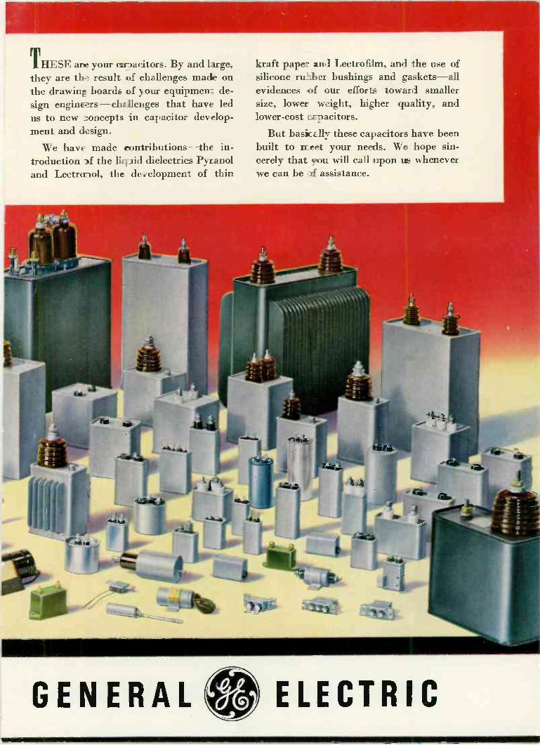
THESE are your ca -)ac itors. By and large, they are the result of challenges macle on the drawing boards of your equipment de- sign engineers-challenges that have led us to new zoncepts in capacitor develop- ment and design.
We have made contributions-the in- troduction 3f the ligaid dielectrics Pyranol and Lectroriol, the development of thin
kraft paper and Lectrofilm, and the use of silicone rummer bushings and gaskets-all evidences of our efforts toward smaller size, lower weight, higher quality, and lower -cost capacitors.
But basiiccllr these capacitors have been built to meet - your needs. We hope sin- cerely that you will call upon urs whenever we can be .af assistance.
GENERAL ELECTRIC

SB -1 * it's the....CONTROL
AND TRANSFER
SWITCH
Approximately full size
DESIGN engineers already have utilized the SB -1 for over 10,000 control combinations on cir- cuits up to 20 amperes at 600 volts a -c or d -c.
Standard parts and a simple basic design mean longer life and low initial cost. There's a standard SB -1 for most jobs. If a standard can't satisfy, we'll build what you want from standard cams, contacts, and fingers of the basic design.
A variety of attractive switch handles, and water -tight, dust -tight, oil -immersed, fabricated - metal, or explosion -proof housings are available to fit your particular installation problems.
Your nearest G -E sales representative will be glad to assist you in the selection of an SB -1. Also, ask him for a copy of GEA -4746 which gives ad- ditional information about the SB -1, or write to Apparatus Department, Section 856-6, General Electric Company, Schenectady 5, New York.
GENERAL ELECTRIC

FEATURES
Direct Reading
Linear Frequency Scale
Continuously Variable Scanning Width Linear and 40db linear log am- plitude scale
Stabilized Frequency Calibrations Continuously Adjustable Selectiv- ity Wide Input Voltage Range
PANALYZOR
MODEL SB_8*
THREE IMPORTANT NEW
PANORAMIC INSTRUMENTS FOR
AF to UHF SPECTRUM ANALYSIS
Panoramic Ultrasonic Analyzer, Model SB -1 for easy, fast Ultrasonic Analysis
USES
High Frequency Vibration Analysis Transmission Line Investigations
Carrier System Monitoring Harmonic Analysis Feedback System Studies
Material Testing Telemetering Medical Studies
PANADAPTOR
MODEL SA8*
FEATURES Variable Resolution, 10:1 Range
Long persistence Cathode-ray Tube 5" Screen
Synchronous or non -synchronous scanning Variable Scanning Rates
Signal Amplitude Compression Continuously Variable Scanning Width
USES
Analyzing AM and FM Trans- mitters Testing Industrial RF Equipment Spotting Spurious Oscillation and Modulation Monitoring Communications Fre- quencies 'Telemetering Checking Diathermy Units Investigating Pulsed RF Signals
An entirely new instrument, the SB -7 is engi- neered to meet the urgent demands for panoramic reception of ultrasonics demands ranging from high speed panoramic analysis of jet engine vibrations to panoramic simplified monitoring of telemetering sub -carriers.
The SB -7, cm automatic scanning receiver, graphically presents frequency and level of sig- nals in the ultrasonic spectrum. Special control features enable selection and spreading out of
any narrow band for highly detailed examina- tion.
Versatility PLUS in RF Spectrum Analysis
Incorporating completely new design features to provide long and short persistence Panoramic displays with extremely fine signal resolution, the SB -8 and SA -8 offer increased possibilities in RF spectrum analysis.
Typical new applications include . . . Energy distribution investigations of pulsed RF signals with low p.r.f.'s Side band analysis of AM and FM signals modulated by low audio frequencies Monitoring of signals very closely adjacent in frequency.
Both Panalyzor and Panadaptor Models are available in the following three types: T-200, T-1000 and T-10,000 having scanning widths of 200 kc, 1 me and 10 me respectively.
PANORAMIC SONIC ANALYZER, MODEL AP -1 *- Complex Audio Wave Analysis with Speed PLUS
Model AP -1 assures faster and far simpler audio analysis by automatically separating and simultaneously measuring the frequency and amplitude of complex wave com- ponents.
Whether your problem is investigation of harmonics, transmission characteristics of
lines or filters, vibration, idtermodulation, noise or acoustics, the startling advantages offered by the Panoramic Sonic Analyzer will provide solutions faster.
ADVANTAGE: Quick graphic views of the 40-20,000 cps spectrum are provided once per second Chances of missing weak or high frequency components are removed Random changes in wave content can be observed Operation is comparatively simple Measures amplitude ratios as high as 1000:1 FEATURES:
Logarithmic frequency scale Linear and linear log voltage scale Wide input voltage range High sensitivity Direct reading Calibrated for absolute or relative amplitu measurements.
*Will be on display at the March IRE Convention, Booth 241-2 Write for Complete Specifications on the above four instruments
ANO RAMI
I HRDIO:%- `:CORPL \ r
10 So. Second Are- '\ . Cable Address
Mount Vernon. N. Y. ' PANORAMIC, NEW YORK
Euluave Canad,an Representative: Canad,an Ma,<onl, Ltd
TELE - TECH March, 1949 21

DU MONT CATALOG ITEMS . - .
HIGH AND LOW VOLTAGE OS- CILLOGRAPHS: Amplifier Ire- quercy response selectable from d -c fo 10 mc. Writing raies up to and exceeding 400 inches raicrsecond. Deflection factors Es kw as 0.01 rms volt inch. Prizes from 5127.20 to 56,073.75.
OSCLLOGRAPH POWER SUP- PLIES: Up to 25,000 volts output for application as final acceler- atinc potential to cathode-ray tube. PRO: ECTION LENS: Projects os- ciLo_raph traces on screen up 'o 31 feet distant. Excellent for ìe:runstrations and lectures. Arpäcable to high -voltage os- =illographs. Type 2542, Cat. No. 1411-E, $103.50.
VOLTAGE CALIBRATOR: For quantitative measurements. Op- erat=s with any oscillograph. Typ= 264-A, Cat. No. 1240-A, $39S0.
ELECTRONIC SWITCH: Provides
O ALLEN B. DU MONT LABORATORIES. INC.
START with Type 314 Oscillo - graph -record Camera. Especially designed for cathode-ray oscillo - graph photography. Maximum convenience. Either single -image or continuous recording. Variable speed, electronically controlled.
a time-sharing system for os- cillograph presentation of two separate traces. Type 185-A, Cat. No. 1072-A, $105.00.
LOW -FREQUENCY LINEAR TIME -BASE GENERATOR: Du Mont Type 215 accessory ex- tends low -frequency range of the time -base of oscillographs. Cat. No. 1189-A, $215.00.
SPECIALIZED EQUIPMENT:Type 279 Dual -beam Cathode-ray Os- cillograph presents Iwo entire- ly separate traces. Cat. No. 1386-E, 51,294.50. Type 275-A Cathode-ray Polar Coordinate Indicator employs a circular time -base. Cat. No. 1250-E, $390.00. Calibrated scales; con -
slant -voltage transformer; trans- ducers; magnetic shields, etc.
DU MONT CATHODE-RAY TUBES: A full line of cathode- ray tubes. A choice of phos- phors suited to your particular needs.
Cat. No. 1366-E, with f/1.5 lens, $1,155.00. Cat. No. 1217-E, with f/2.8 lens, $980.00.
Or with Type 271-A Oscillograph- record Camera (not illustrated). Single -image. Fixed -focus, f/3.5 lens. Cat. No. 1216-E, with mount- ing, $162.50.
DEVELOP your films with Type 2512 Motor -driven Processing Unit. Utterly simple. Accommodates up to 100 feet of 35mm. film. Cat. No. 1372-E, $231.00.
FINISH with Type 2514 Portable Drying Rack. Holds up 4o 200 feet of 35 mm. film. Motor -driven. Provided with heater. Easy rewinding. Unit may be folded up. Carrying case supplied. Cat. No. 1375- E, $232.00.
In oscillography, Du Mont can supply you with the tube, the oscillograph, the accessory. Note partial list of standard items.
And if your oscillograph needs are extremely special, even to the extent of exceeding the broad range of our standard equipment, Du Mont can now place at your disposal the services of our Instrument Model Shop which is equipped to de- sign, develop and manufacture non-standard cathode-ray equipment, or to modify existing equipment and designs. Consult us.
e Detailed literature on request. Equipment demonstrations arranged-no obligation.
ALLEN B. DU MONT LABORATORIES, INC., PASSAIC, N. J. CABLE ADDRESS: ALBEEDU, NEW YORK, N. Y., U.S.A.
22 TELE - TECH March, 1949

Federa/è Shielded Balanced
300 -Ohm Lead-in Cable
. :.
INTELIN K-111
Minimizes Noise, "Snow" and "Ghosts" Due to Transmission Line Pick -Up!
A MAJOR ADVANCE IN
TELEVISION TECHNIQUE
Developed by FEDERAL
Offered Only by FEDERAL
Patent Pending
AVAILABLE IMMEDIATELY
Here is the development for which the industry has been waiting.
It is a shielded, balanced 300 -ohm line-Intelin K-111-developed and produced by Federal-and only by Federal.
Tests have given positive proof that Intelin K-111 goes far toward solving the lead-in problem that has been a major obstacle to television progress. K-111 protects against transmission line pick-up of ignition, streetcars, fluorescent lights, diathermy and practically every other type of noise, "snow" and "ghosts" which interfere with picture clarity. This new lead-in won't pick up re -radiation from nearby lead-ins in urban areas. In rural areas, where signal strength is weak, Intelin K-111 provides greatly improved reception by reducing the noise level.
Now manufacturers can obtain 4, lead-in that protects the quality per- formance they build into receivers of 300 -ohm input impedance. Antenna kit makers can greatly improve their products. And, by changing to Intelin K-111, servicemen can call a halt to many of the customer complaints that take the profit out of service policies.
Intelin K-111 is also recommended for a pick -up -free connection be- tween antenna post and input stage of FM and TV receivers-and for test equipment and other HF applications. For information, write to Depart- ment D-166.
Federal Telephone and Radio Corpora/lot!
KEEPING FEDERAL YEARS AHEAD... is IT&T's world-wide research and engineering organization, of which the Federal Telecommunication Laboratories, Nutley, N. J., is a unit.
SELENIUM and INTELIN DIVISION, 900 Passaic Ave., East Newark, New Jersey
In Canada: Federal Electric Manufacturing Company, Ltd., Montreal, P O.
Export Distributors: International Standard Electric Corp. 67 Broad St., N. Y
TELE TECH March, 1949 23

The best features of Presto's dual motor
gear drive with the overhead mechanism
and turntable of the famous Presto 6-N.
YES, engineers have often asked us for a compact, economical yet high -quality re-
corder. Now you may have it in the Presto 66-G for standard and microgroove recording.
Here is a unit ideally suited and priced for the typical broadcast station or large tran- scription manufacturer. List price, Standard Model, $996! ($70 additional for micro- groove.)
Here's perfection in total speed regulation and very low mechanical disturbance, thanks to the standard Presto dual motor gear drive. Here's high -quality recording, too, for the 66-G, of course, includes the Presto 1-D cut- ting head.
You'll find 66-G equal to the most exacting recording tasks when used with suitable am- plifiers such as Presto 92-A recording ampli- fier and 41-A limiter amplifier.
I FOR HIGHEST FIDELITY ... IT'S PRESTO DISCS
Microgroove, even more than standard recording, demands a perfect disc. The answer is Presto. For, sixteen years ago, Presto made the first lacquer -coated discs ... and today Presto discs are first in quality.
gi`13 RECORDING CORPORATION
Paramus, New Jersey
Here's the Recorder
You asked for!
READY NOW: Magnetic Tape Recorder Presto will show its new super quality magnetic tape recorder at Booths 25-26 at the I.R.E. Show, March 7th. Be sure to see it!
Mailing Address: P. O. Box 500, Hackensack, N. J.
In Cortado: WALTER P. DOWNS, LTD., Dominion Sq. Bldg., Montreal
WORLD'S LARGEST MANUFACTURER OF INSTANTANEOUS SOUND RECORDING EQUIPMENT AND DISCS
24 TELE - TECH March, 1949

tr'iJI,Jut?,2L2 TELEVISION TELECOMMUNICATIONS RADIO
O. H. CALDWELL, Editorial Director * M. CLEMENTS, Publisher * 480 Lexington Ave., New York (17) N. Y.
ELECTRONIC MOBILIZATION NIGHTMARE!- The next war will be radio -electronic to an extent far outreaceing anything we attained during World War II. When the next D-day strikes, hundreds of thousands of intricate radio and electronic devices will have to be ready or quickly completed, the start of a vast outpour- ing of electronic equipment eventually adding up to many billions of dollars. For, this "next time", there will be no year or two to get ready, after the first as- sault is made. It is clear therefore that military elec- ronic production must be prepared for, now. Plant management and employes must be familiarized with military needs without delay. But-
ON ALL SIDES WE ARE BLOCKED-Today radio manufacturers are busy with peacetime production, notably TV. Engineering staffs are overloaded with current commercial designs. Electronic managements are patriotic, but they must watch payrolls and balance sheets, too. Meanwhile military procurement methods are so complex, involved and bunglesome that it costs hundreds to thousands of dollars for a manufacturer even to look at a set of government specifications, and he has little hope of ever earning back his outlay after going through all the elaborate paper work, bids, con- tracts and inspections which military regulations im- pose.
MILITARY MEN ARE HELPLESS also, because of peace -time red -tape imposed by top -brass and depart- mental rules. These regulations (which defeat rather than aid the military purpose), the officers on the pro- curement firing -line cannot amend or change. And so, (as those who attended the recent Army Day meeting of the Boston AFCA had impressed upon them), the nation and the industry find themselves today in a nightmare of electronic frustration. We see an elec- tronic war bearing down upon us, we know how to make the electronic weapons we need, and we have the factories. But industry and the armed forces cannot find a peace -time way to get started with the vast job on which the nation's future existence may depend!
EXECUTIVE ACTION MUST BREAK DEADLOCK -To break this needless, senseless deadlock, to get the electronic manufacturing machine off dead -center,- prompt executive action is needed, at top Washington levels. The patriotic radio -electronic industry is ready to do its share, as evidenced by the Electronic Advisory
Committee Plan fully outlined on the following pages. But there will have to be some top electronic planning in Washington, too. Also immediate slashing of the re- strictive regulations that are tying the hands of both the military and electronic -production men who are all eager to get going with this vital job!
TO SWELL FM AUDIENCE-With 750 FM stations now operating and some 966 authorized, a full FM broadcast service is now available almost nation-wide. But the bottleneck persists in the small number of FM receivers yet in the homes of the public. The FM audience could be greatly increased during coming years if every TV set produced were arranged to bring in the 88 -108 -MC FM band, with video circuits cut off.
A great and economical gain for the public would result.
SERVICE BEGINS IN DESIGN ROOM-The whole success of television now depends on prompt repair and maintenance of the TV sets in use. Television receivers are complex and sensitive devices and even the best of them need occasional chassis adjustments. This fact needs to be taken into account from the beginning, in designing the TV receiver and its cabinet. Easy access should be provided to all vital parts even if this means hinged sides and removable panels to give convenient and easy servicing of the video innards.
SALARIES UP-Engineering starting salaries for 1948 increased 11 percent over similar salaries for the preceding year, according to one Eastern survey. Chemical engineers led off with a starting -salary average of $264. Mechanical and civil engineers started at $256. And electrical engineers, mostly in communica- tions and electronic activities, got initial pay checks of $251, just about the average for all engineering groups.
QUARTER CENTURY-In May, RMA will celebrate its 25th Anniversary. Meanwhile our own publishing organization will mark its 28th year in radio magazine work, with a direct line of radio -electrical publications that go back to broadcasting's earliest efforts. In May, therefore, Tele -Tech will help celebrate this radio industry milestone with special features looking ahead rather than backward-looking ahead to TV's promise of a second quarter century far eclipsing all that has gone before!

Radio -Electronic Industry
Munitions Board gets outline of procedure for readying all US radio - electronic plants and facilities in preparation for war emergency
ANY sound mobilization plan should:
1) Answer the question as to wheth- er there is CAPACITY to meet the strategic needs of the Mili- tary Services and the civilian economy.
2) Provide means for determining deficiencies in capacity, in end items, component parts, raw ma- terials, labor and skills, so that remedial steps can be planned PRIOR to an emergency.
3) Make the transition from peace to war rapid, effective and smooth.
4) Simplify the procurement proce- dures.
5) Keep industry abreast of re- search and development.
6) Finally and most important, pre- pare all individual elements of in- dustry in peace time for their war time task.
Manufacturing Capacity Having determined at the outset
what any sound mobilization plan should accomplish, the various sug- gested means for doing the job have been studied by the Task Commit- tee of the Electronic Equipment In- dustry Advisory Committee.
Large-scale paper planning (Con- tingent Contract Plan - Phase I) has been suggested as one of these means, particularly to determine industry capacity. The Task Com- mittee considers that the benefits of such planning can be obtained by other means at much less cost, and because of reduced expenditure of engineering and administrative man hours, with greater industry ac- ceptance.
The Task Committee submits that statistical information, with a work- ing formula for its application, can be obtained at a fraction of the cost of all-out paper planning. This in- formation will provide an adequate working basis for the guidance of Government and industry on this important question of capacity.
The Task Committee regards such a statistical survey as manda -
Members of Task Committee Which Prepared Plan
George M. Gardner, Wells -Gardner Co., Chicago, Chairman.
Paul F. Hannah, Raytheon Mfg. Co. H. L. Hoffman, Hoffman Radio Corp. David R. Hull, Federal Tel. & Tel. Co. W. A. MacDonald, Hazeltine Labor-
atories. Jacob M. Marks, Fada Radio &
Electric Co. R. C. Sprague, Sprague Electric Co. W. Walter Watts, RCA -Victor.
tory and recommends that it be made by Government through an independent agency or agencies, with the cooperation of industry.
When the statistical survey has been completed, then civilian and Service needs should be matched against the capacity of industry to produce. It then becomes the re- sponsibility of Government to de- termine what remedial steps to cor -
Task Committee Membership Is Experienced
All of the members of the Task Com-
mittee had important procurement ex-
perience during the War, on either the
government or industry sides. Colonels
Hannah and Watts carried large pro-
curement responsibility for the Signal
Corps; Captain Hull was chief of the
Navy Bureau of Electronics. Chairman
Gardner, Mr. Marks, Mr. Hoffman and
Mr. Sprague conducted important radio
manufacturing operations, and Mr. Mc-
Donald pioneered the "leader" type of operation coordinating special produc-
tion by some 50 concerns.
rect disclosed deficiencies should be taken in peace time.
When M Day comes, mobilization of the electronics industry should have accomplished five fully -coor- dinated steps: First, the stages of evolution of a
product preceding production must have received attention and steps have been taken to insure the continuation of essential re- search, development and engi- neering during the emergency.
Second, each selected end equip- ment manufacturer must have necessary technical knowledge or know-how, manpower and facili- ties to create, design, develop and manufacture needed apparatus.
Third, there must be made avail- able to the end manufacturer the necessary special and standard parts, pieces and components sup- plied at a rate sufficient to meet his needs.
Fourth, there must be made avail- able to the parts suppliers suffi- cient raw materials so that the parts, pieces and components can be fabricated. Such materials must come directly from their natural sources or from a stock pile and be supplied at a suitable rate.
Fifth, sufficient engineering, tech- nical and skilled production man- power must be frozen to insure industry's ability to carry out its assigned program in the National defense. Of these five objectives, by far
the most important is the need for know-how as of M Day. This can best be accomplished through ac- tion by The Munitions Board and other legally constituted Govern- ment agencies to use intelligently the powers now given them in con- nection with current procurement. This action contemplates: 1) Utilizing NOW -existing produc-
tion facilities in connection with current procurement.
2) Participation by industry AS A WHOLE, particularly that major portion of the industry which is
26 TELE . TECH March, 1949

War Mobilization Plan
Text of plate as presented to munitions body at Washington February 16
by Electronics Equipment Advisory Committee, F. R. Lack, chairman
not now participating in design, development and/or manufacture of military electronics equipment. All companies in the industry, whether small, medium or large, should be encouraged to contrib- ute their fair share to research, development, pilot runs and pro- duction.
3) Providing to the individual ele- ments of industry a sufficiently uniform flow of work to justify establishment and maintenance of military departments suitably staffed and equipped to handle work loads.
4) Following the successful pattern employed in World War II in the electronics industry of providing leadership in educating numbers of companies to the point where they can assume the responsibili- ties of prime contractors, releas-
ing their primes to devote more time and facilities to research, development and pilot production of new equipments.
5) Utilizing to these ends every presently legal aspect of military procurement, including:
(a)-Open competitive bidding in- vited by advertising, especially in cases where needed apparatus has been completely engineered and requires only production. If appa- ratus so contracted for is expected to be on the list of equipment to be procured in an emergency, then the successful bidder should ap- pear in the planning as the ulti- mate producer of this equipment should an emergency occur. This of course should be subject to change as the interests of the Gov- ernment may require. (b)-Where highly complex tech- niques are required, competitive bidding should be among com- panies on the Services' qualified bidders lists, including small and
large companies, for the protection of Government. Here again the successful bidder should become a part of the mobilization planning for this apparatus. (c)-Negotiated contracts, where it appears that for reasons of en- gineering skill or know-how, or unique facilities, such negotiated contracts are in the best interests of Government.
The mechanism by which Gov- ernment can through the medium of current procurement encourage the industry to acquire the neces- sary know-how already has been outlined, but further than this, any practical Plan must have as its ob- jective the spreading of this know- how throughout the whole of the industry. To accomplish this, four fundamental steps are required: 1) To assure that every company
shares the load and that no capa - (Please turn to next page)
HUGE MASS OF PAPER WORK INVOLVED IN PRODUCING SINGLE ELECTRONIC UNIT
PHOTOGRAPH DELETED BY NAVY CENSOR AS WE GO TO PRESS
After this page was on the press, the photograph in this position, which had previously been approved for publication by the Navy Public Information Office, Third District, had its release summarily cancelled by higher -level orders telephoned from Washington.
The picture showed the tremendous quantity of unduplicated drawings, specifications, orders and cor- respondence involved in the manufacture of only one small routine piece of government electronic equip- ment.
This huge mass of paper work, weighing nearly 400 lbs., was inspected by the editor and a group of
radio -electronic manufacturers at Boston, Army Day, Feb. 4, and has since been seen, we understand, by
other industrial and military groups.
The manufacturing drawings alone numbered 1650 and made a pile 24 inches high,-one of 26 piles
of papers involved in getting ready to manufacture this single small electronic unit.
TELE -TECH March, 1949 27

ELECTRONIC MOBILIZATION PLAN (Continued)
ble company is overlooked or overloaded, the procurement pro- grams of the three Services must be coordinated. Since single serv- ice procurement of end items in this "custom-built" industry ap- pears generally impractical, ap- pointment by the Government of a four -man procurement program directing committee is clearly in- dicated. This should include rank- ing and qualified officers repre- senting the three Services and one civilian, chosen by the three Service Secretaries, completely divorced from industry but rec- ognized by his former position in industry as being eminently qualified. This four -man commit- tee would be charged with prop- er coordination and channeling of current procurement to all com- panies able to handle it.
2) The Munitions Board Electronics Equipment Industry Advisory Committee already appointed would make itself available for use as consultants and technical advisors to the four -man Govern- ment directing committee, when requested.
3) The four -man Government di- recting committee would recom- mend to the Services, capable companies in the industry which the Government would ask to as- sume the responsibility of edu- cating and bringing along other companies, through the medium of sub -contracts.
4) To encourage those elements of the electronics industry not now participating, to prepare for their wartime role. It should be recognized that with
the current situation in television it is going to be difficult for Gov- ernment to persuade the industry as a whole to participate. This is not an industry looking for an add- ed load, particularly if that load re- quires any appreciable effort from
the highly skilled technical person- nel who are already overloaded and of whom there is a shortage. For this reason, the essential element of this Plan, which is the spreading of the know-how, must be imple- mented by Government in terms that are attractive to the industry.
This Plan presupposes a minimum of paper planning, and a maximum of actual industry experience gained by production of needed equipment. Experience on Government con- tracting, including design and de- velopment, is best secured through actual production in connection with current procurement.
Before production can begin, tools have to be checked and remade, materials and components have to be cut and tried and the organiza- tion- has to be trained.
For these reasons, Government should procure, provided it is with- in the current needs of the Services, a pilot quantity of any piece of equipment that appears to have a good chance of military use.
The Task Committee believes that military liaison with industry is essential. This should be estab- lished by geographical areas rather than by individual plants.
Industry needs military liaison officers to interpret for its benefit Government's requirements. Mili- tary liaison officers necessarily must check Government contract prog- ress, and make indicated inspec- tions.
Such military liaison officers, if properly utilized by both Govern-
ment and industry, can be of great service in such specific cases as ar- ranging draft deferment of key per- sonnel, and advising on Security, thus freeing industry management for full performance of its normal functions. Such liaison should be integrated with existing Service field offices.
By mobilization planning that considers the electronics equipment industry as a whole and not as in- dividual companies, the following results should be accomplished: 1) Operation of a majority of the
electronics industry for military production under a well-defined and coordinated plan.
2) Each prime contractor would have a well -staffed, well -organ- ized military department, suscep- tible to rapid expansion at short notice.
3) Each prime contractor would be- come experienced in design, de- velopment and manufacture of military equipment, in proportion to its ability to contribute.
4) Each prime contractor would be - responsible by mutual agreement for specified other companies to be used as sub -contractors, thus placing responsibility for educa- tion of these other companies in the most experienced hands.
5) The capacity of the industry for military procurement would be determined at minimum cost.
6) Timely correction of deficiencies in capacity disclosed by compari- son of requirements with existing facilities could be instigated by the Services.
7) Materials, man power and skills would be made available for im- mediate industrial mobilization.
Statistical Analysis of Labor & Material Requirements
The Task Committee has given careful consideration to the prob- lem of establishing the load that may be placed upon all industry to satisfy the needs for electronic
equipment for the military Services in the event of an emergency.
There is already available in Government laboratories, bureaus
(Continued on page 70)
MEMBERSHIP OF ELECTRONIC EQUIPMENT ADVISORY COMMITTEE
Fred R. Lack, Western Electric Co., Chairman; Dr. W. R. G. Baker, Gen- eral Electric Co.; John Ballantyne, Philco Corp.; Frank M. Folsom, Radio Corporation of America; Paul V. Galvin, Motorola; Ray C. Ellis, Raytheon Mfg. Corp.; Max F. Bolcom, Sylvania Electric Products Inc.; David W. P. Hilliard, Bendix Radio Division; Walter Evans,
Westinghouse Electric Corp.; Dwight R. G. Palmer, General Cable Corp.; S. W. Gilfillan, Gilfillan Bros. Inc.; W. J.
Halligan, Hallicrafters Co.; E. H. Locke, General Radio Co.; H. A. Ehle, Inter- national Resistance Co.; A. D. Plamon- don, Jr., Indiana Steel Products Co.; Monte Cohen, F. W. Sickles Co.; F. D.
Bliley, Bliley Electric Co.; R. C. Sprague,
Sprague Electric Co.; C. A. Warden, Jr., Superior Tube Co.; J. H. Miller, Weston Electrical Instrument Corp.; Paul J.
Kruesi, American Lava Corp.; R. O. Driver, Wilbur B. Driver Co.; Jerome J.
Kahn, Standard Transformer Corp. in
addition to the membership of the spe-
cial Task Committee shown on list on page 26.
28 TELE - TECH March, 1949

International Export Possibilities
for Television
Virgin territories - differences in transmission standards - open new markets for all types of transmitting and receiving equipment
Ry JOHN H. BATT15ON Allocations Engineer, American Broadcasting
THE very rapid growth of televi- sion in the United States has
astonished not only American en- gineers and manufacturers, but has excited the interest and imagina- tion of people all over .the world. In the three short years since the end of the war the art has come into its own, so that at the end of 1948 over 50 television stations are serving 46,916,200 people in 29 markets, where approximately 900,- 000 sets are in use.
The only other country that ap- proaches the US in its television operations, is Great Britain. Before the war this country had a service that was second to none, but due to the risk of TV transmission inter- fering with the vital radar installa- tions service had to be suspended during the war. Thus, when peace was declared, TV in Great Britain was still where it was in 1939. However, whatever the industry lost in operations and experience during that time it has more than made up in activity in the export and foreign trade field. The British have ever been a race of exporters and foreign traders, and this in- stinct combined with their present urgent need to export, has given American business a very strong competitor in foreign markets.
While the sphere of internal trade for U. S. firms is good, the outside business will require fighting for with all the weapons in the manu- facturers' armories. Perhaps the term "inside" as used above is mis- leading. The intention was to in- clude the whole of the North Amer- ican continent together with South
About the Author John H. Battison is currently working on
a book on "International Broadcasting
Practices." His experience with inter- national radio dates back to 1934 when
he became affiliated with the old Radio
Normandy station in Belgium. Later he
joined the firm of E. K. Cole as a receiver design engineer. Then he served with the British Air Ministry and at the outbreak of the war he was flying fighters in the
RAF. After six and a half years of combat
and transport flying he come to the United
States and joined KMBC (Midland Broad-
casting Co.) as research engineer. In
June, 1947 he became allocations engineer for the American Broadcasting Co. He is
presenting a paper on American Broad- casting before the British IRE this month.
America, excluding . Canada, since judging from recent rumors and news items the die is almost cast in favor of British equipment and/ or standards in the latter country. However, from a technical point of view as well as a good neighbor policy it would seem that adoption of the same standards as those of the US would result in better programming since they would then become exchangeable, viewers on each side of the border being able to tune . in each other's pro- grams, and only one set of receiver standards need be set up. It would appear to be a logical step for all countries of the same continent to adopt the same standards in the interest of international coopera- tion.
In line with this we find
w York- City
that GE has applied the theory, and sold a 5 KW transmitter to Radio Televisao do Brasil. This equipment will be used by PRA -9, Rio de Janeiro, with the standard FCC transmission characteristics. It is reasonable to suppose that this sale will not be the last one, and that it 'presages the adoption of US standards in at least one country. It is not too much to hope that the habit will spread, and that all the countries south of the border will follow suit.
Canada offers a different prob- lem, however. By virtue of her po- sition she has become very similar to the US in many respects, and because of distance from "the old country," has adopted US ideas of radio and standards of living. Prob- ably, left to her own devices the choice would be US standards. After all, as a signatory to NARBA, Canada is bound to follow North American radio practices. But Eng- land is making a strong play for this market and has sent Sir Ernest Fiske, the managing director of
Electrical and Musical Industries, the company which manufactures trans- mission equipment for the BBC, to Canada to negotiate the sale of equipment. The decision will prob- ably be forthcoming soon, but with vivid memories of what happened to recent pollsters the author pre- fers to keep his opinion to himself! Whatever the outcome, it is certain that a large market will exist in Canada, either for receivers, trans- mitters or both. At present, curren- cy questions act to restrict trade,
(Please turn to next page)
TELE - TECH March, 1949 29

.J
TV EXPORT POSSIBILITIES (Continued)
but these will not exist forever, and many US firms have Canadian branches where US equipment, modified for other standards, if necessary, can be produced. France is a tempting market, and one where just now it would seem that US business should be very much to the fore. There is no doubt that strong efforts are being made to persuade the French to adopt Brit- ish standards. And the arguments are very reasonable too! After all there are very few receivers in France, and those that there are operate on 450 lines, the standard of 1937. The British 405 line transmis- sion would not be hard to receive with a very slight modification and the difference between 405, 450 and 525 lines is not so much that it can easily be noticed by a layman. It is understood that a recent decision has been made to keep the present 450 lines for the next ten years; however, one can only wait and see. The ultimate goal there is high def- inition television with 800 to 1000 lines used. The figure 819 lines has been put forward quite frequently, and it seems probable that the re- gional stations will be set up on this frequency as well as the one in Paris on the Eiffel Tower.
The pièce de resistance occurred last summer when the French Thomson -Houston Company picked up BBC transmissions over a dis- tance of 100 miles at Calais. The picture is said to have been quite good and no trouble was found in holding synchronization. This opens
up a new argument in favor of com- mon standards. Doubtless the sig- nificance of this has not been lost on politicians of both countries and it may be an additional count against the US salesman. Logic dic- tates that Europe and England should use the same system, and England has a large audience al- ready.
The Netherlands is a country where television is in a state of flux although standards very similar to ours have been adopted, the only difference being in the frame and line frequencies which are 25 per second and 567 respectively. One transmitter has been installed at Eindhoven and a second one will shortly be erected at Hilversum to serve the center of the country.
The world picture is good for makers of television equipment, but it is no time for the US to rest on laurels of internal achievement. RCA has had its touring team out in Europe for some time and dem- onstrations have been given in Spain and Italy. Both were very well received and created interest in American achievements. As already reported GE has sold a transmitter to Brazil. But these are hardly even scratches on the surface of the world of television. This continent should be a natural for American persuasiveness, and even if other standards are adopted, the equip- ment, at least, can be "made in America"!
Australia has authorized televi- sion transmitters for six state capi -
This massive and elaborate machine is a telecine installed at Alexandra Palace, Hq. of the BBC Television Service. It televises any standard full-length or short feature film.
Country
tais and tenders have been invited. The initial estimated cost of $1,600,- 000 includes 500 receivers. As far as is known no further action has been taken.
Poland is in the market for radio equipment, and has issued a license to Great Britain to import to the value of $400,000, in radio equip- ment. Television will soon be seen in Warsaw, work having com- menced on its first transmitter.
Export and Related Costs
One factor which must enter into the considerations of exporters is the return that will be possible for a given expenditure. To the rela- tively high cost of producing a set must be added the cost of freight and import duties as well as per- haps local taxes. To balance this the standard of living and the ac- tual cost of living must be consid- ered. For example consider a semi- skilled French workman. He earns
Foreign Television Operations
Operating Remarks Status
Brazil Rio De G.E. Equip - Janeiro Expected 1949 ment
Denmark Copenhagen Expected 1949
France Lille Expected 1949 Paris On the Air
Germany Cologne After 1951 Hamburg Expected 1951
Great Britain Birmingham Expected 1949 London On the Air 405 lines
Netherlands Eindhoven On Air -
Experimental Hilversum Proposed
South Africa Expected 1953 Spain
Barcelona Probably 1951 USSR
Leningrad On the Air Moscow On the Air
567 lines
405 lines
567 lines 567 lines
00
Probably RCA Equipment 441 lines 441 lines
'Standards and frequencies are still a controversial issue in France. The Compagne Francaise Thomson Houston uses 729 lines on 41-49 MC. Phillips has 567 line system on about 61 MC. Sadir company suggests 450 lines and Radio Industrie 819 lines. Compagnie des Compteurs uses 1000 lines in their high definiton system. It seems quite possible that final standard will be over 700 lines. Because there will never be as many stations in the cities of foreign coun- tries as there are in the U.S. spectrum space is not too critical. This allows use of wider channels and consequent improvement in definition.
625 lines interlaced, 25 frames, 87-100 MC. German TV started in 1928 and had regular programming during the period 1935 to 1944. Will start as US and UK have agreed on final standards.
30 TELE - TECH March, 1949

$27.00 weekly. On this he supports his family. Now compare a US semi -skilled auto worker; he will average three times this amount, and run a car. The nearest the Frenchman gets to a car is a tandem cycle, and radio with one tube miss- ing so he can only get the local station. How can he pay for a tele- vision receiver? Yet these men make up the larger part of the populations of many countries. As- suredly, governments will pay for equipment; but how will the men in the street? Belgium is one of the more prosperous countries today but it is doubtful if many people could afford a television receiver. Of course receivers for export can be simpler since most areas will have only one station and therefore the thirteen or seven channels of the home market will not be re- quired. Sets for England for in- stance need only receive one chan- nel which can be retuned when the owner moves from one region to another. It is not likely that any foreign countries will have more
than one station in any town for many years to come. It should be noted in this connection that the RMA has set up a committee to examine foreign markets.
The table below sets forth the vital statistics for a number of countries. Wherever the cost of liv- ing and the wage rates are given it is possible to form an opinion of the export possibilities. These are the latest available figures and are for 1947 unless noted otherwise.
From the point of view of the manufacturer who wants to expand his trade to include foreign televi- sion markets there are a number of means at his disposal, any one of which should bring satisfactory re- sults. This presupposes that the manufacturer is one of the smaller firms now manufacturing television receivers rather than one of the big companies which is already well known and has its own foreign dis- tribution organization. It is as- sumed not many of the smaller firms now making receivers will wish to expend the time and money
Foreign Vital Statistics Table For Comparing International Export Prospects
Imports from
Type of Total Imports U.S.A. Country Currency (Millions) (Millions)
Cost of Radio Receiver Population Living Wages Oensity, 1948 (Thousands)
Austria Schillings 1,048,497 146 149 13.7% 6,816 - 41,846 Australia Pounds 156,781 7,414 (1945)
Argentine Pesos 5,349 2,431 16,109 339 12.6% Belgium Francs 85,528 22,655 8,453
Bolivia Pounds 10,959 3,546 3,590 157 Brazil Cruzieros 22,789 13,975 48,000
Canada Dollars 1,820 1,405 12,307 403 600 Chile Pesos 1,307 570 5,552
(approx. )
Denmark Kroner 3,087 605 169 189 27.2% 4,045 Eire Pounds 130,812 29,114 2,953 East Africa Pounds 37" 12,152 -
178 Ecuador Sures 500 3,340 0.9% Egypt Pounds E. 103 11 16,550
720 700 Finland Marks 46,888 24% 14.97% 3,871 France Francs 45,781 5,235 14.52% 41,980
(1938) Iceland Kroner 117 310 26.27% 131
177,122 5,105 Italy Lire 413,804 4,921 4.5% 45,486 Mexico Dollars 1,348 1,152 21,165 -
(1944) Netherlands Guilder 42,512 1,195 198 15.48% 9,636 Norway Kroner 12,057 159 18.22% 3,079 -
(1945) New
Zealand 1,676 (1944) Poland Dollars 11,704 3.6% 23,622
799 205 Portugal Cantos 5,735 2.1% 7,185 (1943)
Peru Gold Soles 338 7,800 0.7 256 1.45% Spain Pesatas 26,491 (1943)
Sweden Kroner 705 24% 144 29.6% 144 Switzerland Francs 1,225 136.8 21.87 4,389 Turkey Liras 685 228 1.09% 18,860 Union of
S. Africa Pounds 206 30 11,392
This is radio only. US radios comprise 30% of all radios. 1942 figures show a ratio of 0.7 US to UK imports.
The total average radio receiver density is 8% for a population of 554,500,000 people. (I.B.O. figures).
Television outside Broadcast Fleet No. 1. Aerial Van with extensible aerial raised
in transmitter development for a somewhat nebulous overseas mar- ket.
Probably the best way of all is to make contact with large retail organizations in the country in question and arrange to have them act as distributors. Naturally this requires very careful investigation by the exporter to assure financial stability. Another similar approach would be to secure the services of a national of the country when he is in the US, and arrange for him to act as an agent.
Trade Directories Effective
Of course there are various trade directories published in all parts of the world and in many different countries. An advertisement in one of these often brings good results, and most certainly will place a manufacturer's name before a num- ber of possible consumers. The cost for an insertion is not excessive. Details may usually be obtained from the US Dept. of Commerce.
It should be remembered, how- ever, that the large companies are usually well established in most overseas countries, and it takes a lot of hard work for a new company to "muscle in", even in a small way.
(Continued on page 66)
TELE . TECH March, 1949 31

R; E
vv ITH "Radio - Electronics - Servant of Mankind" as its
keynote, the Institute of Radio En- gineers will convene in New York City for this year's national con- vention on March 7-10. Headquar- ters of the convention, as usual, will be at the Hotel Commodore and Grand Central Palace. The sched- uled technical program includes 28 sessions on subjects embracing virtually every branch of radio - electronics, and six symposia on nuclear science, network theory, electronic computers, radio aids to navigation, semi -conductors and marketing. An aggregate of 172 papers will be presented during the four days that the convention is in session.
IRE Convention and Four -day gathering, scheduled for March 7-10,
The number of exhibitors at Grand Central Palace will exceed last year's by more than 30, provid- ing a total of 216 impressive dis- plays of the latest significant devel- opments in post-war research. Tele- vision kits, microwave test equip- ment, microgroove record changers, tape recorders, and remote -control equipment are only a few of the products which will be exhibited, some for the first time.
Benjamin E. Shackleford, IRE president in 1948, will be toast- master at the president's luncheon on March 8 and will introduce Stu- art Bailey, this year's president. Toastmaster at the annual banquet on March 9 will be Raymond F. Guy, manager of NBC's Radio and Allocation Engineering Dept. Frank Stanton, president of CBS, will be a featured speaker at the banquet. The topic of his address will be "Television and the People."
TECHNICAL PAPERS PROGRAM MONDAY, MARCH 7
Systems I - Modulation Systems "Development of a High Speed Communication
System"-Donald S. Bond, RCA Laboratories "Distortion in a Pulse -Count -Modulation System
with Nonuniform Spacing of Levels"-P. F. Panter and W. Dite, Federal Telecommunica- tion Laboratories
"Cross -Talk Considerations in Time -Division Mul- tiplex"-S. Moskowitz, L. Diven, and L. Feit, Federal Telecommunication Laboratories
"Experimental Verification of Various Systems of Multiplex Transmission"-D. R. Crosby, RCA Victor
"Interference Characteristics of Pulse -Time Modu- lation"-E. R. Kretzmer, M.I.T.
"Factors Involved in the Design of an Improved Frequency -Shift Receiving System"-Colin C. Rae, Naval Research Laboratory
Antennas I
"Some Properties of Radiation from Rectangular Waveguides"-J. Bolljahn, Univ. of Calif.
"Elliptically Polarized Radiation from Inclined Slots on Cylinders"-G. Sinclair, Univ. of Toronto
"A Broadband Transition from Coax to Helix"- C. O. Lund, RCA Laboratories
"Theory of End -Fire Helical Antennas"-A. E. Marston and M. D. Adcock, Naval Research Laboratory
"Equivalent Circuits for Coupling of Waveguides by Apertures"-N. Marcuvitz, Polytechnic Inst. of Brooklyn
Symposium: NETWORK THEORY "Modern Developments in the Topology of Net-
works"-R. M. Foster, Polytechnic Inst. of Brooklyn
"A Summary on the Status of Linear Network Theory"-E. A. Guillemin, M.I.T.
"Recent Developments in Broadband Active Net- works"-Linvill, M.I.T.
General Review of Linear Varying Param- eters and Nonlinear Circuit Analysis"- W. R. Bennett, Bell Telephone Laboratories
Instruments and Measurements I - Microwave "Measuring the Efficiency of a Superheterodyne
Converter by the Input Impedance Circle Diagram"-H. Wheeler and D. Dettinger, Wheeler Laboratories, Little Neck, N. Y.
"Electrolytic -Tank Measurements for Microwave Delay Lens Media"-S. B. Cohn, Sperry Gyroscope
"Impedance Instrumentation for Microwave Transmission Lines"-P. A. Portmann, Naval Research Laboratory
"A Michelson Type Interferometer for Microwave Measurements"-B. A. Lengyel, Naval Re- search Laboratory
"A Broadband High -Power Microwave Attenua- tor"-H. J. Carlin, Polytechnic Inst. of Brooklyn
"An Absolute Method for Measuring Microwave Power of Low Intensity"-H. Herman, Naval Research Laboratory
Audio "The Reproduction of Sound"-H. F. Olson,
RCA Laboratories "New Developments in Studio Design in Europe" -L. L. Beranek, M.I.T. "The Technique of Television Sound"-R. H.
Tanner, Northern Electric Co., Ltd., Belle- ville, Ontario
"The Measurement of Nonlinear Distortion"- A. Peterson, General Radio Co.
TUESDAY, MARCH 8
Antennas II "Antenna Systems for Multichannel Mobile Tele-
phone"-W. Babcock and A. W. Nylund, Bell Telephone Laboratories
"Wide -Angle Metal -Plate Optics"-J. Ruze, Cam-
bridge Field Station, U. S. Air Force, Cam- bridge, Mass.
"The Measurement of Current and Charge Dis- tributions on Transmitting and Receiving Antennas"-T. Morita, Harvard Univ.
"The Diffraction Pattern from an Elliptical Aper- ture"-R. Adams and K. S. Kelleher, Naval Research Laboratory
"A Low -Drag Aircraft Antenna for Reception of Omnidirectional Range Signals in the 108- to 122 -MC Band"-J. Shanklin, Collins Radio Co., Cedar Rapids, Iowa.
Passive Networks I - Synthesis "Amplifier Synthesis through Conformal Trans-
formation"-J. Pettit and D. L. Trautman, Jr., Stanford Univ.
"Exact Design of Bandpass Networks Using n Coupled Finite -Q Resonant Circuits (n = 3 and 4 )"-M. Dishal, Federal Telecommunica- tion Laboratories
"Network Approximation in the Time Domain"- W. H. Huggins, Cambridge Field Station, Air Materiel Command, Cambridge, Mass.
"A Method of Synthesizing the Resistor -Capacitor Lattice Structure"-J. L. Bower, J. T. Fleck, and P. F. Ordung, Yale Univ.
"The Design of Frequency -Compensating Match- ing Sections"-V. Rumsey, Ohio State Univ.
Instruments and Measurements II - Oscillography "An Impulse Generator-Electronic Switch for
Visual Testing of Wide Band Networks"- T. R. Finch, Bell Telephone Laboratories
"A 50 -MC Wide -Band Oscilloscope"-A. Levine and H. Hoberman, Federal Telecommunica- tion Laboratories
"A Timing -Marker Generator of High Precision" -R. C. Palmer, DuMont Laboratories
"The Evaluation of Specifications for Cathode - Ray Oscillogra1,hs' -P. S. Christaldi, Du Mont Laboratories
"Photographic Techniques in Cathode -Ray Oscillo- graphy"-C. Berkley and H. MaiSberg, Du Mont Laboratories
Electronic Computers "The Binac"-J. P. Eckert, Jr., J. W. Mauchly,
and J. R. Weiner, Eckert-Mauchley Computer Corp., Philadelphia, Pa.
"An Electronic Differential Analyzer"-A. B. Macnee, M.I.T.
"An Analog Computer for the Solution of Linear Simultaneous Equations"-R. M. Walker, Watson Chemical & Scientific Laboratory, N. Y. C.
"The Electronic Isograph for a Rapid Analogue Solution of Algebraic Equations"-B. O. Marshall, Jr., Cambridge Field Station, Air Materiel Command, Cambridge, Mass.
"A Parametric Electronic Computer"-C. J. Hirsch, Hazeltine Electronics Corp., Little Neck, N. Y.
Symposium: ELECTRONIC COMPUTERS "The Binac"-J. W. Mauchly, Eckert-Mauchly
Computer Corp., Philadelphia, Pa. "Mark III Computer"-H. H. Aiken, Harvard
Univ. "IBM Type 604 Electronic Calculator"-Ralph
Palmer, DuMont Laboratories "Electrostatic Memory for a Binary Computer"-
F. C. Williams, Manchester Univ., Manches- ter, England
"Counting Computers"-G. R. Stibitz, 393 South Prospect St., Burlington, Vi."Programming
of a Chess Game on a Computer" -Claude Shannon, Bell Telephone Labora- tories
Wave Propagation I - Television "VHF Television ---Propagation Aspects"-E. W_
Allen, Jr., FCC "Propagation Variations at VHF and UHF"-
K. Bullington, Bell Telephone Laboratories "Propagation Tests at UHF"-J. Fisher, Philco
Corp. "A Test of 450 -MC Urban -Area Transmission to
a Mobile Receiver"-A. Aikens and L. Y. Lacy, Bell Telephone Laboratories.
"Echoes in Transmission at 450 MC from Land to Car Radio Units"-W. R. Young and L. Y. Lacy, Bell Telephone Laboratories
Passive Networks II - Analysis "Impedance Curves for Two -Terminal Networks" -E. Michaels, Northwestern Univ.
32 TELE - TECH March, 1949

Radio Engineering Show
will include presentation of 172 papers in many phases of radio -electronics
"An Analysis of Triple -Tuned Coupled Circuits" -N. Mather, Princeton Univ. "The Bridged Parallel -Tee Network for Sup-
pressed -Carrier Servo Systems"-C. F. White, Naval Research Laboratory
"Transient Response of Linear Networks with Amplitude Distortion"-M. DiToro, Federal Telecommunication Laboratories
"Spectrum Analysis of Transient -Response Curves"-H. Samulon, General Electric Co.
Components and Materials "Subminiaturization of IF Amplifiers"-G. Sha-
piro and R. L. Henry, National Bureau of Standards
"New Applications of a Four -Terminal Capacitor" -A. A. Pascucci, Radio Hispano Suiza, S.A. Barcelona, Spain
"Frequency Control Units"-A. E. Miller, Miller Co., N. Bergen, N. J.
"Type 5811 and Type 5807 Tubes, The Smallest Commercial Pentode Amplifiers"-L. G. Hec- tor and H. R. Jacobus, Sonotone Corp.
"Conductive Plastic Materials"-M. A. Color, A. Lightbody, F. Barnet, and H. Perry, Naval Ordnance Laboratory
Nucleonic Instrumentation "Industrial Thickness Gauges Employing Radio-
isotopes"-J. Carlin, Polytechnic Inst. of Brooklyn
"The Design of a G -M Counter Tube for High Counting Rates"-W. Managan, Victoreen Instrument Co., Cleveland 3, Ohio
"Electrometer Tubes and Circuits"-F. H. Starke, Raytheon Mfg. Co.
"Proportional Counter Equipment for Beta Detec- tion"-W. Bernstein, Brookhaven National Laboratory
"A High -Voltage Supplier for Radiation -Measur- ing Equipment"-R. Weissman and Stewart Fox, Nuclear Instrument and Chemical Corp., Chicago 10
Symposium: NUCLEAR SCIENCE "The Fundamental Particles"-D. J. Hughes,
Argonne National Laboratory, Chicago 80 "The Detection and Measurement of Nuclear
Radiation"-H. L. Andrews, National Insti- tute of Health
"The Effects of Ionizing Radiation on Tissue"- J. P. Cooney, Atomic Energy Commission
"The Application of Nuclear Radiation to Indus- try' -J. R. Menke, Nuclear Development Assoc., N. Y. C.
WEDNESDAY, MARCH 9
Television I "A Unidirectional Reversible -Beam Antenna for
Twelve -Channel Reception of Television Sig- nals"-O. M. Woodward, Jr., RCA Labora- tories
"A Method of Multiple Operation of Transmitter Tubes Particularly. Adapted for Television Transmission in the Ultra -High -Frequency Band"-G. H. Brown, W. C. Morrison, W. L. Behrend, and J. G. Reddeck, RCA Laboratories
"Transient -Response Tests in the WPTZ Tele- vision Transmitter"-R. C. Moore
"The Synchronization of Television Stations"- R. D. Kell, RCA Laboratories
"Television by Pulse -Code Modulation"-W. M. Goodall, Bell Telephone Laboratories
Symposium: RADIO AIDS TO NAVIGATION "The Radio Technical Commission for Aeronautics -Its Program and Influence"-J. H. Dellin-
ger, Radio Technical Commission for Aero- nautics, Wash., D. C.
"Frequency Allocations td the Aeronautical Ser- vices above 400 MC"-V. I. Weihe, Air Transport Assoc., Wash., D. C.
"Experimental Multiplexing of Functions in the 960 to 1600 -MC Frequency Spectrum-Its Influence on Weight and Complexity of Equipment"-P. C. Sandretto, International Telecommunication Laboratories, N. Y. C. and R. I. Colin, Federal Telecommunication Laboratories
"The Philosophy and Equivalence Aspects of Long Range Radio Navigation Systems"-M. K. Goldstein, Office of Naval Research
"The Future in Approach and Landing Systems" -H. Davis, Watson Laboratories, Red Bank, N. J.
Active Circuits I
"G Curves as an Aid in Circuit Design"-K. A. Pullen, Ballistic Research Laboratory, Aber- deen Proving Ground, Md.
"A Direct -Coupled Amplifier Employing a Cross - Coupled Input Circuit"-J. N. Van Scoyoc
Stuart L. Bailey President, Institute of Radio Engineers, 1949
and G. Warnke, Illinois Institute of Tech- nology
"Annular Circuits for High -Power Multiple -Tube Generators at VHF"-D. H. Preist, Eitel - McCullough, Inc.
"Considerations on Electronic Multicouplers"- W. R. Aylward and E. G. Fubini, Airborne Instruments Laboratory, Mineola, N. Y.'
"Improved Degenerative Regulators"-Y. P. Yu, North Dakota Agricultural College, Fargo, N. D.
Instruments and Measurements III "Radar Circuit Powered X -Ray Movie Equipment
for Operation at 150 Frames per Second"- D. C. Dickson, Jr., C. T. Zavales, and L. F. Ehrke, Westinghouse
"An AM Broadcast Station Monitor"-H. Sum- merhayes, General Electric Co.
"The Speed of Electronic Switching Circuits"- E. Williams, Carnegie Institute of Tech- nology and D. F. Aldrich, Westinghouse
"A Magnetostrictive Delay Line"-E. Bradburd, Federal Telecommunication Laboratories
"An Electromechanical Strain -Gage Multiplier"- C. Woods, E. St. George, L. Isenberg, and A. C. Hall, M.I.T.
Electronics I - Tube Design and Engineering "Microphonism Investigation"-Lester Feinstein,
Sylvania Electric Products "A Critical Survey of Methods of Making Ceram-
ic -to -Metal Seals and Their Use for Vacuum Tube Construction"-R. P. Wellinger, Univ. of Illinois
"Rugged Tubes"-G. W. Baker, Kip Electronics Corp., N. Y. C.
"An Improved Method of Testing for Residual Gas in Electron Tubes and Vacuum Systems" -E. W. Herold, RCA Laboratories
"Design Factors, Processes, and Materials for the Envelope of a Metal Kinescope"-R. D. Faulkner and J. C. Turnbull, RCA
Television II "The Measurement of the Modulation Depth of
Television Signals"-R. P. Burr, Hazeltine Electronics Corp., Little Neck, N. Y.
"Development and Performance of Television Cam- era Tubes"-R. B. Janes, R. E. Johnson, and R. S. Moore, RCA
"An Anastigmatic Television Deflection Yoke and Associated Circuits"-K. Schlesinger, Motor- ola, Inc.
"A High -Efficiency Sweep Circuits"-B. M. Oli- ver, Bell Telephone Laboratories
"Progress Report on UHF Television"-T. T. Goldsmith, DuMont Laboratories
Wave Progogation II "An Analysis of Distortion Resulting from Two -
Path Propagation"-I. H. Gerks, Collins Ra- dio Co., Cedar Rapids, Iowa
"On the Origin, of Solar Radio Noise"-A. V. Haeff, Naval Research Laboratory
"Geometrical Representation of the Polarization of a Plane Electromagnetic Wave"-G. A. Deschamps, Federal Telecommunication Lab- oratories
"Propagation Conditions and Transmission Reli- ability in the Transitional Microwave Range" -T. F. Rogers, Cambridge Field Station, AMC, Cambridge, Mass.
"A Forward -Transmission Echo -Ranging System" -D. B. Harris, Collins Radio Co., Cedar Rapids, Iowa
Active Circuits II "A Laboratory and Analytical Analysis Compar-
ing the L -C Toroidal Filter with the Parallel - Tee Feedback Amplifier Filter"-A. J. Stecca, Naval Research Laboratory
"A Peak -Picker Circuit"-M. J. Parker, Naval Ordnance Laboratory
"Low -Frequency Synchronized Sawtooth Genera- tor Providing Constant Amplitude Sweep with Aperiodic Synchronization Input"-P. Yaffee, Naval Ordnance Laboratory
"High -Power Sawtooth Current Synthesis from Square Waves"-H. E. Kallmann, 417 River- side Drive, New York 25 N. Y.
"Regenerative Amplifiers"-S. P. Yu, North Dakota Agricultural College, Fargo, N. D.
"A Rectifier Filter Chart"-R. Lee, Westing- house
Instruments and Measurements IV "High -I mpedance Millivolt Measurements above
5 MC"-W. K. Volkers, Millivac Instru- ments, New Haven, Conn.
"Some Aspects of the Performance of Mixer Crystals"-P. D. Strum, Airborne Instru- ments Laboratory, Mineola, N. Y.
"A Wide -Band Audio Phasemeter"-J. R. Ragaz- zini and L. A. Zadeb, Columbia Univ.
"A Device for Admittance Measurements in the 50- to 500 -MC Range"-W. R. Thurston, General Radio Co., Cambridge 39, Mass.
"An Improved RF Capacitometer"-E. F. Travis and T. M. Wilson, General Electric Co.
"A Radio Frequency Discharge Phenomena and its Application to Mechanical Measurements" -K. S. Lion and J. W. Sheetz, M.I.T.
Electronics II - Electron -Tube Cathodes "The Effects of Various Barium Compounds with
Respect to Cold -Cathode Behavior as a Func- tion of Life in a Glow Discharge"-H. Jacobs and A. P. LaRocque, Sylvania Electric Prod- ucts
"Oxide -Cathode Properties and their Effects on Diode Operation at Small Signals"-G. C. Dalman, Polytechnic Institute of Brooklyn
"Microanalysis of Gas in Cathode -Coating Assem- blies"-H. Jacobs and B. Wolk, Sylvania Electric Products, Inc.
"Exposure of Secondary -Electron -Emitting Sur- faces to the Evaporation from Oxide Cath- odes"-C. W. Mueller, RCA Laboratories
"The Use of Thoriated-Tungsten Filaments in High -Power Transmitting Tubes"-R. B. Ayer, RCA
THURSDAY, MARCH 10
Systems II - Relay Systems "A Microwave System for Television Relaying"-
J. Z. Millar and W. B. Sullinger, Western Union Teiegraph Co.
"Synchrodyne Phase Modulation of Klystrons"- V. Learned, Sperry Gyroscope Co.
(Continued on page 64)
TELE - TECH March, 1949 33

A New Processional Tape Recorder
THIS month the Fairchild Re-
cording Equipment Corp. starts production on its new Model 100, Professional Tape Recorder which up to now has been used experi- mentally by the Columbia Broad- casting System. Combining top quality performance with low tape speed this equipment, through the provision of many new and unusual features, simplifies editing and spotting, provides for exact cueing, and eliminates, most if not all of the operational objections heretofore considered inherent in magnetic tape machines.
Fig. 1 shows a top view of the Model 100 and identifies the various surface controls and components. In operation, . the tape moves from left to right across the erase, record and playback heads. Conventional- ly, drive capstans are located be- tween the playback head and the take-up reel and serve to pull the tape across the heads. In this new machine the capstan and pinch roll
assembly are located between the supply reel and the erase head and operate to supply tape smoothly and uniformly across the head as- sembly to the take-up reel. This new design feature permits wow- and-flutterless operation almost en- tirely independent of the condition of the tape on the supply reel. This is the result of the combination of an oversize drive motor, a massive (8 pound) fly wheel, and a capstan pinch roll combination which com- pletely eliminates tape slippage, all of which operate effectively to "lock out" tension variations in the sup- ply reel due to sticky splices or non - uniformly wound tape.
The capstan drive mechanism provides, by means of the entirely new "Synchroll" principle, what is claimed to be a new degree of mo- tion stability. Long-term speed variations including the effect of tape creep and slippage are less than 0.1% which permits program timing to within 4 seconds per hour.
TOPE ;SUPPLY
DISC
Pi NCH ROLLER
!: :'.E _A STAN
METER SWITCH REDORO
2. FORS
3, ERASE
TAPE GUIDES
INPUT PAD ER POWER SWITCH
'APE TAKE-uP DISC
IDLER
RECORDING HEAD PLATE ASSEMBLY
PLAY' -E..- BEGS,
CRECE HEAL'
CONTROL LIGHTS I. GREEN EtATFAG,, 2, WHITE - WIND
RED -- RECORD
MOTOR CONTROLS REVERSE STOP
3, FORWARD
FUNCTION CONTROLS VOLUME OUTPUT I, PEAR 3. RECORD INDICATOR PAD D WIND 4.OFF
Fig. 1: (Above) Top view of the Model 100 Professional Tape Recorder identifies the various surface components and controls.
Fig. 2: Details of mechanism involved in loading or removing tape. Container with tape is placed over spindle (B) so that drive pins (C) engage with holes In tape hub. Carton is then pulled away and the hub -cap (A) is screwed down causing plate (E) to recede against spring tension until the tape rests on disc surface. Newly de- signed tape carton (upper right) greatly facilitates storage, shipping and handling.
The wow and flutter content due to all causes is less than 0.05%. The machine provides for operation in either direction in both the play and rewind positions. Since these reversals can be made almost in- stantaneously without stopping and without in any way endangering tape breakage, the editing and spot- ting problems are greatly simplified.
Similarly, the transition from the play or record position to the rewind position can be made almost instantaneously. Heretofore, one of the serious objections to the use of tape for some purposes has been the always present danger of losing part or all of a program as a result of the tape spilling from the roll. This can be eliminated by using two-sided reels, but their ad- vantages are more than offset by the high cost, weight, bulkiness, and lack of stiffness in sizes large enough to handle a half hour or hour program. The use of the con- ventional removable disc, which is a sort of one-sided reel, consider- ably facilitates the handling of the tape but does not minimize damage in case of mishandling. The new machine solves this problem by a novel approach. The tape is wound around a core which fits on the hub of the non -removable tape discs, and
IIIIIIIIIIIIIIIIIIIIIIIIIIIIIIIIIIILIIIIIIIIIIIIIIIIIIII IIIIIIYIIIIIIIIIIINIIIIIIIIIIIIIIIIIIIIIIIIIIIIIIIII
? a
K
34 TELE - TECH March, 1949

is supplied in a specially designed carton. To place the tape on the ma- chine, the supply disc hub cap is removed, and without removal from the carton, the tape roll is placed on the drive pins as shown in Fig. 2. These drive pins are spring supported and serve to hold the tape approximately 1/8 -in. above the supply disc. The carton is then pulled away from the tape and the replacing of the hub cap depresses the tape to its proper operating po- sition. In removing the tape this procedure is merely reversed.
The take-up disc is identical to the supply disc and thus the tape can be loaded or unloaded at either point. Once tape has been joined from the supply to the take-up reels, the threading is completed by simply dropping the tape in place on the recording head plate as shown in Fig. 1.
The hubs have been so designed to take the proposed NAB standard cores so that the tape from other machines can be used if desired and in addition, without change, the standard RMA reels, which are used primarily for 71/2-in./sec. recording, can be mounted.
Unitized Construction An interior view of the complete
equipment is illustrated in Fig. 3. Unitized plug-in chassis construc- tion is used throughout and five major components in the form of bias, record and playback ampli- fiers, power supply and control chassis (left to right, top to bottom) comprise the instrument. The con- trol panel tilts forward on hinges for ready access to the switch and meter connections on the rear, and the top panel may be removed to reveal the motors and driving mechanism. The recording head plate is separately detachable and is attached to the top surface through a six point kinematic (ball and groove) type mount. The entire drive unit including the capstan is similarly a self-contained unit and can be removed by taking out 4 screws. Unitized construction was adopted throughout the design be- cause the equipment is primarily designed for broadcast studio and master control room applications.
In line with this Fairchild has established a factory replacement type service for adjustment or re- pair work that has to be done on any of the three heads on the re- cording head plate. The unusual re- sponse characteristics achieved by this equipment is due in large meas- ure to the precision design and con-
struction employed on each indi- vidual head assembly which are unique in that both the scanning gaps and inductance are adjustable. The average installation is not equipped for maintenance work of this level and hence it becomes ad- visable for the manufacturer to per- form such adjustments in the in- terests of unit interchangeability. An idea of the degree of uniformity to which these heads can be ad- justed may be seen in Fig. 4 which shows graphically the adjusted re- sponse characteristics of three dif- ferent production type playback heads. In no case will the variation between heads as supplied under this rotating stock plan differ by more than 1 DB. It is important to mention, also, that both the record and playback heads are provided with a means of adjusting the azi- muth of the pole piece gap so that tapes recorded on other machines can be played back with a minimum loss in frequency response due to "scanning" effects. The playback head can be adjusted while the ma- chine is in operation and, if a wide range monitor speaker is used, this adjustment may be made aurally for optimum high frequency re- sponse in about ten seconds.
Another interesting feature about the head plate assembly is that the
IQ
p -15
126 Heed
* 127 Head
128 Head
1 1 II FREQUENCY WC
10
Fig. 4: Variation in adjusted response of three playback heads does not exceed 1 DB
3 .10
10 100 - 1000
FREQUENCY CPS
10.000
Fig. 5: Overall frequency response of the equipment is from 50 to 15 000 cps ± 1 DB
5
3
044 48 52 56 60 64 66
OUTPUT 06 Above Widebon0 Noise
Fig. 6: For 2% total harmonic distortion the noise level is better than 60 DB down
Fig. 3: Interior view of complete equipment shows unitized construction used throughout to speed and ease any required maintenance
only vertical tape guides on the machine are an integral part of this plate and hence the replacement of a head assembly does not require any additional adjustments on the machine.
Fig. 5 shows the overall frequen- cy response of the equipment to be within ±1 DB from 50-15000 CPS while the power curve of Fig. 6 shows that when a 1 KC signal pro- duces 2% total harmonic distortion in modulating the tape, the attend- ant wide band noise level is more than 60 DB below the output signal. In normal operation an audio input level ranging between -10 to +20 DBM is required and the output may be adjusted between the limits of -20 to +10 DBM.
Experience has indicated that there is an optimum bias level . for each type of tape which permits the best balance between dynamic range and 'frequency response and that with a proper bias supply the tape noise level is independent of the bias level. The bias supply on this machine is instantly adjustable and the bias value may be read on the VU meter, thus permitting optimum adjustment for whatever tape is used. This adjustment is usually, except for dubbing purposes where an exact level must be maintained, an unnecessary refinement and re- peated tests with a composite reel of tape made up of fifty foot sections of three quite different types of tape' has shown that it is almost, if not completely, impossible for the listener to detect the transition
(Continued on page 64)
TELE TECH March. 1949 35

Design and Performance
Fig. 1: Apparatus used by author includes power supply, mold, furnace for controlled dielectric cooling, L & N Recording potentiometer and an electret storage desiccator
Waxes and resinous materials that retain a permanent charge promise a new series of electronic components
AN electret is a dielectric body and the other surface has a nega - that retains an electric moment tive charge. Negligible decay of
after the removal of the applied these charges occurs if the electret DC field. This principle, while far from being new, opens intriguing avenues of exploration in electron- ics research. The word ELECTRET was coined and used by O. Heaviside to describe such a permanently po- larized dielectric, the electrical ana- logue of a permanent magnet. a 16
However, Eguchi was the first to make and describe' practical elec- 14 trets. They are obtained when cer- tain waxes and resinous materials, such as Carnauba wax, rosin, and z beeswax, alone or in mixtures, are melted and allowed to solidify while exposed to a strong, externally ap- plied, unidirectional electric field.
The electric field polarizes the molecules of the dielectric and as LL
the mass solidifies these polarized w 5
molecules are frozen into their ex- á 4
cited positions. "Free electric 3
charges" then appear on the electret .x 2 surfaces. That is, at room tempera- 1
tures one electret surface bears a á 0 0 02 0.4 06 free charge that is positive in sign a 1) Phil. Mag. (British), Vol. 49, page 178, 1925
E u 18
12
10
8
7
6
DISTANCE FROM SURFACE IN
Fig. 22 Graph of approximate field strength at various distances from electret surface
a
Liuil ELECTRET cm
By EDWARD D. PADGETT East Orange, New Jersey
is completely covered with a metal foil "keeper" which short-circuits the polarized surfaces, and serves the same function as the "keeper" on a magnet.
These "free charges" are a form of energy, the amount of which can be measured when mechanical work is done against the charged surfaces. Work done is the product of a force and a distance. In the electrostatic system of units (c.g.s. system) work done is the product of an electrical force and a distance.
If one wishes to induce a charge on the top plate of a capacitor the necessary energy must come from the work done in mechanically dis- placing one plate in a vertical direc- tion when it is near the charged electret surface. In other words, to induce a charge on the plate, work must be done by moving the plate to or from the electret surface. The sign of the induced charge will be
Fig. 3: Equipment arranged as a capacitor, used to induce charge on electret surface
36 TELE - TECH March, 1949

Characteristics of "Electrets"
HIGH VOLTAGE INSULATORS ON FURNACE WALLS
10,000 VOLT
POWER SUPPLY
%2" 4-40 MACHINE SCREW
ALLIGATOR CLIPS
2
IL
BAKELITE INSULATOR Iÿ"x,"s5cm
POLARIZED DIELECTRIC IN FOIL LINED MOLD
f
6 cm
S 38' - 5%2cm - ?
Fig. 4: Details of insulated transite stand and electric furnace which provides controlled dielectric cooling
Fig. 6: In microphones electrets replace polariz- ing voltage sources. Equiv- alent voltage and ampli- fier circuit is at right.
opposite that on the electret surface. If work is done against this
charged surface, an appreciable field strength will exist between the elec- tret surface and the adjacent plate. If the distance between the two is decreased, the field strength will increase. When the distance is 5 mm., for a 9 cm. square electret surface and a 20 cm. square plate, the approximate field strength is 2000 volts per centimeter. When the distance is less than 1 mm. the approximate field strength ap- proaches 20,000 volts per centimeter - a respectable magnitude indeed! A graph of approximate field strength versus distance between the electret surface and the plate appears in Fig. 2.
As measured under ideal labora- tory conditions the density of sur- face charge (total charge on an electret surface divided by electret surface area) on several types of electrets varies from about 0.20 to 6.00 e.s.u./cm2. These values may be compared to Lord Kelvin's theo- retical maximum of approximatély 10 e.s.u./cm2.
(Please turn to next page)
9 INCHES
BRASS TUBING MOUNTED IN BAKELITE SUPPORT IN CAVITY OF cm FURNACE. /2
POLARIZED DIELECTRIC IN MOLD ----_
5 cm
3cm
SQUARE
HIGH VOLTAGE INSULATORS ON FURNACE WALLSy
+
ALLIGATOR CLIPS
10 KV.
5 tm
_ 2
I« 2.5cm
BAKELITE BLOCK
i- - 8 cm
r 5 INCHES
Fig. 5: For cylindrically shaped electrets a mold made from brass tubing approximately 0.030 -in. thick is employed
Fig. 7: (Insert) Molten dielectric is poured into mold lined with aluminum and foil. (Below) An external electric field (5 to 10 KV/CM) is applied while dielectric cools slowly

CHARACTERISTICS OF "ELECTRETS" (Continued)
Fig. 8: Disc electrets may be mounted on plastic rods to facilitate handling when making surface charge measurements. Stored electrets are wrapped in metal foil "keepers"
A convenient way to handle elec- trets, when making surface charge and field strength measurements, is to mount them on Polystyrene han -
dies as shown in some of the photo- graphs, to eliminate discharging them, and avoids the introduction of unnecessary errors into the tests.
Fig. 9: Details of an experimental suspender disc electrometer. The degree of mirror deflection is indicated on a centimeter scale placed 115 cm. away from the electret
18 cm
APPROX
11
ELECTROMETER r`24 c cm4 3
li/ /QUARTZ NSULATORS ,QUARTZ
O.D. TUBING
TG - cm /
_ ./.. 10
cm
qPPROX
10 cm
T 2
[cm i
_C.,/ l -.i mm
/ 41.- *mg.*
5X cm / -%
%,
1/4" THICK BRASS PLATES
NICHROME#28 SMALLER WIRE
ELECTROMETER PLATES 0.040 INCH FLAT BRASS
MIRROR GLUED TO ELECTRET
- ELECTRET
QUARTZ SUPPORTS ARE APPROX. 3 c m
HIGH BY I cm WIDE 6" LONG.
While electrets can be made in an interesting variety of sizes and shapes, disc types are the easiest to make and test. Here the molten di- electric material is poured into a metal mold that is actually a paral- lel plate capacitor. To the mold and its contents, a strong external field is applied from a power supply, as in Fig. 1 which is a photograph of equipment used by the author in making electrets. The units are then allowed to cool slowly (about 2 hours) in a furnace, or oven, to room temperature, using a setup as in Fig. 4. Controlled cooling reduces the cracking tendency of these wax type dielectrics and improves the electrets. In a convenient form shown in photographs, the lower mold electrode is cup shaped and the top electrode is a flat disc. Both are lined with 0.001 inch metal foil (aluminum or tin) to facilitate sub- sequent handling. The wax dielec- trics used in making electrets have a volume contraction of as much as 20% during the cooling process. As it shrinks it pulls the foil with it, and thus reduces the tendency to crack. This shrinkage permits easy removal of the foil lining with the completed electret from the mold.
Spacing of Electrodes
Eguchi used a circular cup 20 cm. in diameter by 1 cm. deep as the lower electrode. The upper electrode just touched the dielectric surface and was held in place by three in- sulated strings. Andrew Gemant2 used a similar mold but with re- duced dimensions when he verified Eguchi's claims. Gemant placed three small ebonite spacers 120° apart in the molten wax to main- tain a distance of 1.6 mm. between electrodes.
Present tendencies are to elimi- nate these spacers by mounting the upper electrode on an insulated support or stand (as in Fig. 3) . It is necessary to obtain an external electric field that is uniform and uni -directional. The field that ex- ists between two charged, closely spaced, parallel plates meets this requirement. A simple method is to make electrets that are disc shaped. The factor that governs the thick- ness of an electret is the distance between electrodes at which this externally applied field becomes non -uniform. The surface area of an electret is limited only by prac- tical considerations in the experi- menter's mind.
E. P. Adams of Princeton Uni -
38
2) Phil. Mag. (British) #20, page 929, 1935
TELE - TECH March, 1949

versity made cylindrically shaped electrets, using a mold that was a cylindrical capacitor (Fig. 5). Two brass tubes about 15 cm. long were mounted, one inside the other, on a Bakelite block. The molten di- electric was poured into the space between the tubes, which were con- nected to a 4000 volt power supply. This potential was maintained on the mold until the assembly had cooled to room temperature. For a 5 mm. distance between electrodes and the applied potential difference of 4000 volts, the strength of the external field applied to the dielec- tric to make the electret was 8000 volts per centimeter.
As in the case of disc electrets, better electrets will be obtained, if the cylindrical mold and the di- electric are cooled to room tempera- ture in a furnace (a cooling time of about 2 hours is satisfactory). To make suitable electrets an external field strength of between 5000 and 10,000 volts per centimeter must be applied to the dielectric and the cooling time must be greater than 1 hour.
Electrets find practical use in electrometers and electromechani- cal transformers, (microphones, etc.)
Electret electrometers are ad- vantageous because of their low ca- pacitances and linear scales. One of Gemant's electrometers had an impedance, at 60 cycles (assuming the capacitance of the system was about 1.1 µµf), of 3 X 10⁸ ohms; an ohmic resistance equal to that of the insulation; and a sensitivity of 2 mm. per volt. This instrument was suitable for use as an a.c. voltmeter, or null instrument. Fig. 6 shows one method of assembly. Or, for a simple experimental version, the disc can be mounted between two pieces of I mil. aluminum foil and used di- rectly.
Suspended Disc Electrometer
In a suspended disc electrometer (Fig. 9) an electret and a small mirror are attached to a thin Nichrome wire in and insulated from the brass and Plexiglass case. The electrometer plates are mount- ed on quartz insulators inside the case. When the plates are charged to the d.c. potential difference to be measured, the electret deflection is proportional to the applied p.d. The mirror deflection is indicated on a centimeter scale placed 115 cm. from the electret. An electric couple 3) British patents 435,950 and 438,672. See also
U. S. patents 1,523,898, 1,702,438 and 1,804,364.
Fig. 10: Testing the electret chronograph system. Sketch is detailed in insert. Electret leads go to oscilloscope
acts on the electret when the d.c. voltage is applied which rotates the electret until the elastic restoring force of the Nichrome suspension wire is reached. The sensitivity de- pends in part on the size of suspen- sion wire used.
The dimensions are approximate because an electret 4 cm. in diam- eter should be cut down until it has uniform polarization through- out its mass. The diameter then might be approx. 2 cm. The fixed plates are moved about with respect to the suspended electret until best performance is obtained.
Gemant described his electret mi- crophone illustrated in Fig. 6 as fol- lows: ".... both the diaphragm and the metal mesh possess a certain capacity against the free electret surface, and the ratio of their in- fluenced charge depends on the ratio of their partial capacities. When the diaphragm moves, as the result of an impinging sound wave, the capacity will change and alter the charge ratio. There will be an alternating current in the transform- er, which, for small amplitudes, has the same wave form as the acousti- cal wave. The apparatus acts, therefore, like a "microphone".
Although transformer coupling is theoretically possible it is expensive and rather impractical. High im- pedance devices of this type tend to pick up hum from nearby 60 cycle outlets and appliances. Electret mi- crophones require no polarizing
+1
HETERO-Ir o
I
f- ¢ al« -2 W c W -3 W V Q N
E 4 '\ aN D. LU
Ó d 5
of one pair of pickup units or electronic timer amplifier
LOWER SURFACE
2 3 4 5 6
TIME (WEEKS) H0MOCHAROE
7
UPPER S RFA E
Fig. 11: Graph showing the growth of surface charge for 7 week old Carnauba wax electret
voltages. While they are amazingly interesting devices before they can move from the experimental labora- tory to the production line, stabili- zation of several variables must be solved. Several types have appeared on the market from time to time, however, which contain several modifications for the explanation of electret microphone behavior.
Making electret microphones is a matter of transforming the acousti- cal energy directed against an elec- tret into an equivalent voltage which is represented by the symbol VA. It can be measured by a VTVM placed across the electret. In order to approach the ideal condition of a non -loading, the electret should
(Continued on page 62)
TELE - TECH March, 1949 39
rIS

Performance Capabilities of Ultimate performance limits, selectivity, and fidelity characteristics analyzed
By GEORGE V. ELTGROTH, Vice President, Eckert-Mauchly Computer Corp., Philadelphia, Pa.
Part I of this article appeared in the February issue.
HAVING now established the os- cillation amplitude existing at
the time t2 with signal currents at the resonance frequency impressed, it now becomes necessary to investi- gate the response to signal currents at other frequencies to establish the receiver selectivity. The circuit of Fig. 7 is again employed for the analysis, with an assumed input current i, of the same amplitude as the reference resonance frequency current but of different frequency. The circuit equation now becomes D2 coo' = wa'A sin (cot + a) whose complementary solution is again given by: i2 = C, sin coot + C2 coswat. Employing (5) again for the deriva- tion of the particular solution: i2 = w02A sin (cot + a)/(wa2 - w2) making the complete expression for the current through the inductance
i2 _ r sin bt , r, cos.. t .,,oA sin (at a) <
+2 1 1
ww; - A2awe-
awo 27r
I I I
o 00 050 5.0 x 9ºo 000 Rao , a iw woo twa z at, vw 5x02100 weo,acov.o.,m}Eoo
DEGREES
Fig. 9: Relationship of circuit voltage to time. Solid envelope is for zero start angle while dotted lines are for an angle of r/2
n/ß/m2 + n2 = sin S and n/m tan S:
m coscoot +n sin,t = m<n2lcos5 coso0t Sinn siorot)1- ``
7ccos(n0t-6)
3
2 sins twin ; ° tans
w w
ñ w2
casa
Within the range of frequencies about resonance for which the se- lectivity is determined coo/co is sensi- bly 1, in which case S = a so that:
cos (Wot-o) - (13)
(Ill) Also m7.-n2 pOs2a(32,- ssin2a (IV)
and for the voltage across the in- ductance
2
E+L dltdL,erl cos moN°or2 sin ,ot.e.°A2 cos (,oto)Ill ....(II) , ff
At t = 0, both i2 and E are also zero, enabling the determination from (10) that C2 = (-Awa2/woe-w2) sin a and from (11) that C, = (-Awwa/w02-4,2) cos a. Substituting these constants in (11) , the com- plete expression for the voltage is found to be
E=LA o- con , rns..o! =,L +in, sinot
Some rearrangement of (12) will now be undertaken to place it in form for easy employment.
The first two terms within the parenthesis are of the form
mcossot . n sin,,.°t= lnZ oen ,0s z^n2 sin;ö j
I
or letting m/ -/m2 + n2 = cos S,
40 4
in which there is introduced for the test angular velocity w, the equiva- lent quantity (1 + a) coo, "a being the decimal deviation between the test frequency and the resonance frequency, (14) now becomes
3 w m2+n2 = 212111 + (2a +a2 )costa (15)
Bearing in mind that a is an arbitrary start angle inserted to care for the fact that there is no rigid relation- ship in time between the quench voltage and the signal voltage, the extreme values of (15) may be de- termined by inserting the limiting values of cos a. With a = D, (15) assumes its maximum value which is
(16)
and with a = 7c/2, (15) assumes its minimum value of
m2+n2 - 2° Z ( II) 0o d
Inserting (13) and (17) in (12) to find the voltage across the cir- cuit with a start angle a = D it is
that
E=LAI_2 cos (wt+0)-'4 cos (wot+0)1 = llwo-w
AZ fCoswt -coswot1....(18)
° L
With a start angle a = a/2, (13) and (17) are used in (12) , giving for the circuit voltage:
E=LAH- cos (tot +2) cos(wp2)]
wZ f wsin wt-wosin,totl (19)
o L J
The expression (18) is employed in determining the selectivity charac- teristic of the superregenerative re- ceiver, the effect of start angles re- sulting in the voltage (19) in modi- fying the selectivity curve being in- vestigated later. Using the cosine law, the envelope of the voltage wave (18) is found to be
Ed.Z (22-..\11+ I-2 cos (wwo)t=AZ 2-212-2 cosaeot= 4
r
A,m2w221 havers ine aot....(rri)
0 1
This envelope is zero whenever wwot is an even multiple of 27c. On the other hand, it is seen that the envelope of (19) cannot become zero and that its minimum amplitude is
aw F = pZ
occurring at a time corresponding to the minimum of (20) . The dif- ference in the envelope maxima of (18) and (19) is insignificant be- cause of the normally small per- centage difference between the im- pressed frequency and the resonance frequency. The circuit voltage with relation to time is shown in Fig. 9
in which the envelope for a zero start angle is shown in solid line, with the obscuration of the mini -
(21)
TELE - TECH March, 1949

Superregenerative Receivers
Expression for Selectivity It will be remembered that there
was earlier established the fact that the detector output voltage was con- trolled by envelope of the voltage wave in the tuned circuit at the time when the shunt resistance presented by tube VI becomes negative, and that it was therefore concluded that the selectivity could be obtained by comparing the ratio of the voltage envelopes existing at this time in the presence of energy at the reso- nance frequency, and in the presence of energy at an interfering frequen- cy deviating from resonance.
As will be seen the selectivity is closely related to an adjusted quench frequency which is the reciprocal of the period of wave portion two. For brevity, this will be referred to here- after as the "quench frequency."
Fig. 10 shows the voltage enve- lopes for the case of an interfering frequency very close to the reso- nance frequency. Both curves (a) and (b) are substantially straight lines. The ratio is substantially unity at t2 and there is no discrimi- nation. In Fig. 11, the interfering frequency has been farther removed from the resonance frequency and the curvature of the interfering envelope is more clearly seen in Fig. 11(b). Here, the ratio of reso- nance frequency response to inter- fering frequency response at t2 is greater than unity, this not being evident from the sketch due to the readjustment of scale.
In Fig. 12, the deviation between resonance and interfering frequen-
mum produced by the most unfavor-cies has been increased to equal the able start angle, ir/2, indicated in quench frequency. Now there is no dotted lines. response in the tuned circuit to the
interfering signal and the indicated selectivity ratio is infinite. Points at which this is the case may be re- ferred to for convenience as ex- tinction points. The significance of the maximum minimum envelope amplitude given by (21) now be- comes evident, for it indicates that whenever the start angle is a/2, the most unfavorable angle, the enve- lope in Fig. 12(b) does not drop to zero, but to some finite value pre- venting the selectivity ratio from becoming infinite when the devia- tion frequency is equal to the quench frequency. As there is no means of controlling the start angle, this most unfavorable angle must be assumed in deriving the selectivity ratio at this and other similar points. Taking the ratio of reso- nance frequency response to the envelope minimum under the most unfavorable conditions as given by (21) determines the discrimination or selectivity against interfering signals producing an envelope min- imum .at t2. This discrimination ratio is
Az t 2 w0t 2 wp t
ate wno a
wow2 wo-(I+a)214 2(_2a -a2)
As "a", the decimal deviation, is normally fairly small, the equation may be written simply as y = c)ot. To complete the finding of the at- tenuation at an extinction point, reference may now be made back to part I, where it was found that oht was equal to 2it times resonance fre- quency/quench frequency. As un- favorable a ratio f0/f as one might
Y -
Second of Two Ports
expect to encounter is 50:1, corre- sponding to a 500 KC carrier and 10 KC quench frequency. For this condition
Y = 314.16 and 20 log Y = 49.94 (22)
indicating an extinction attenuation of approximately 50 DB for this condition. Normally, f/f may be expected to be in the neighborhood of 500:1, providing far higher ex- tinction attenuations. The selectiv- ity curves which are presented later have been drawn for an assumed maximum attenuation of 50 DB al- though this corresponds to the most unfavorable operating condition of a superregenerative receiver.
Fig. 13 illustrates the voltage en- velopes found in the circuit when. the interfering frequency differs from the resonance frequency by 1.5 times the quench frequency. It will be observed that the discrimi- nation ratio is now much less than that for the lower deviation fre- quency in Fig. 12.
The second extinction point ob- served when the interfering fre- quency differs from the resonance frequency by twice the quench frequency is clearly seen in Fig. 14. There is no necessity for further figures, since it is now obvious that further increases in deviation of the interfering frequency merely in- crease the number of envelope crests and troughs occurring during the zero loss period and successive- ly cause the traverse of additional extinction points. With the above qualitative information concerning the selectivity and the reasons for its existence in mind, the develop- ment of the quantitative selectivity relations from equations (9) and
(Please turn to next page)
Figs. 10-14: (Left to Right) Comparison of volta -e envelope wave fcrms showing conditions for a very low deviation between resonance and signal frequencies. and also the conditions where the deviation in volved is 0.5, equal to 1.5 times, and twice the quench frequency.
tl
O ...911111111111111
..11111111111111111111
t2 VOLTAGES DUE TO SIGNAL
SONANCE FREQUENCY
VOLTAGES DUE TO INTERFERING
DEVIATING
ANCE F EQ,
ti t2 VOLTAGES
Oa SIGNALDUE A7 ' RESONANCERESONANCE fl
O
12 VOLTAGES
SIGNAL AT
ti
O ' ` © AI Al
t2 DUE TO
RESONANCE SIGNAL AT
FREQUENCY
VOLTAGES DUE TO INTERFERING SI NAL
ti
O 12
VOLTAGES DUE TO SIGNAL AT `
O
FRRSONANCE EQUENCY
VOLTAG DUE TOES INTERFERING SIGNAL
'MIMI'
© .. FREQUENCY
VOLTAGES DUE TO INTERFERING SIGNAL
` © Al
1111111111111111
RQ.' VOLTAGES DUE TO INTERFERING SIGNAL
ANCETFOM REQ,
ING SON-
EVIATING RFROMESON-
D- ANCE FRED.
DEVIATING
FREQ.OM -, AN FROM
CE FFREQ,
TELE - TECH March, 1949 41

Y
-2lhaversine a.,°t 2faversine a.,°t 2a
SUPERREGENERATIVE RECEIVERS (Continued)
(20) will now be initiated. As stated before, the selectivity
ratio is the ratio of the envelope amplitudes produced by energy at the resonance frequency and by energy at the interfering frequen- cy. This ratio may be designated by and written
AZ w°t
= (23)
AZ 22'\1haversine a w°t °
in which w (1+a wó I +a
wá -w2 wo-(i+a)Zwó -2a-a2
for which may be taken O - I (24) wów2 2a
since "a" is small. The error intro- duced in the selectivity curves by the approximation of (24) is zero DB in the immediate region of the resonance frequency, and is less than two DB for interfering fre- quencies differing from the reso- nance frequency by 50%. At this point on the selectivity skirt the attenuation has already reached such values that two DB more or less is of negligible consequence. Also in (23),
a.i°t=2naf°t=2naf° deviation freo.
fq quench freq.
Utilizing this, and selectivity ratio is
wot
2
(23) in (22) the found to be:
ad°t
deviation freq. nx
quench freq. ,(25)
Ii iaversine(2nxdeviation freq.)
quench tree.
The negative sign of (24) has been dropped without affecting the re- sults, since it is the ratios of enve- lopes which are being dealt with, and change in the sign of the en- velope term merely indicates in this case a reversal of the phase of the wave within the envelope. The particular significance of (25) lies in the fact that the signal or reso- nance frequency does not appear in the equation, and that the discrimi- nation ratio is therefore a function only of the ratio between the devi- ation frequency and the quench fre- quency. The selectivity of superre- generative receivers is therefore constant on an absolute deviation basis, but not on a percentage de- viation basis, as is the case with normal tuned circuits. The value of 20 log y is plotted in Fig. 1 as the solid line selectivity curve to illus-
trate the attenuation suffered by signals differing from the resonance frequency. Although, according to equation (25) the attenuation of an interfering signal is infinite when the deviation frequency equals the quench frequency, the maximum attenuation shown in the curve of Fig. 15 is 50 DB in accordance with the extinction attenuation predevel- oped in (22). Only five secondary responses are shown on either side of the primary response in Fig. 15, it being understood that others continue beyond those shown on either side of the resonance fre- quency. The dashed line in Fig. 15 is the envelope of the secondary response peaks, and has additional value as indicating a design criteri- on to be later discussed.
The curves of Fig. 15, which have been experimentally corroborated,
10
2 i
3o
A0
9 8 T 6 5< 3 2 1 0 1 2 3 A 5 6 T 8
RATIO OF DEVIATION FREQUENCY TO QUENCH FREQUENCY
Fig. 15: Graph showing optimum selectivity characteristic of superregenerative receiver
Fig. 16: Series resonant analysis circuit used to develop dashed curve In Fig. 15
Fig. 17: Selectivity comparison between superheterodyne and superregenerative re- ceivers (with 5 KC quench wave) at 300 KC
I I I III I
; ,
1 ----.SaWl5eta0YM ReWw
- U Recalwef
+
10
- 11
2Q
1 30 140 ! R
SO
60
/
1 ; 1
1
I 1
I 1
, : -20 -IS -10 -5 0 05 410 +15 +20
KILOCYCLES DEVIATION FROM RESONANCE FREQUENCY
show that the superregenerative re- ceiver attenuates very strongly in- terfering signals displaced from the desired signal by integral multiples of the quench frequency, while sig- nals at intermediate points are sub- ject to much less attenuation. If, therefore, the receiver is to be em- ployed in a frequency where, be- cause of regulations, the transmit- ting stations are spaced in the spectrum at uniform intervals, as in the 540-1700 KC band in the U. S., the receiver may be so de- signed that when tuned to a desired signal, the extinction points in the selectivity curve coincide with the frequencies of all other channels in the spectrum. The operating selec- tivity under such circumstances is, to all intents and purposes, that of the primary response rather than that of the envelope of the secon- dary responses. It is as though a blocking grid were automatically swung into place on every other channel in the spectrum when the desired signal is tuned in, and by taking advantage of this peculiar property of the superregenerative receiver its utility may be extended to frequency bands much lower than hitherto thought possible. Where the channel spacing is ir- regular and unpredictable, advan- tage cannot be taken of the special characteristics of the selectivity curve, and in this case the criterion of performance is the envelope of the secondary response peaks.
The dashed curve of Fig. 15 is, as earlier intimated, the envelope of the secondary response peaks, but deviates from this relationship in the primary response region. This curve is of especial significance as it is the selectivity curve of a con- ventional tuned circuit having a Q equal to 78% of the number of sig- nal cycles elapsing during the zero loss period of the superregenerative circuit with which it is compared.
The dashed curve of Fig. 15 was developed for a simple series reso- nant circuit as shown in Fig. 16. The current at resonance is I = E/R and the current for a signal voltage re- moved from resonance is I = E/VR' + (X5, - Xe)2. The selectivi- ty ratio y = VR2 + (XL - X°) 2/R in which the following substitutions may be introduced: XL = (f/f0)X°; Xe = (f°/f)XQ; XQ = RQ resulting in the expression:
Y VRZ+RZQZ(fo-) +n2 (1 (26)
f (1 + a)fQ in which a is again
42 TELE - TECH March, 1949

1.1 _1111R
the decimal deviation, while afo is the deviation frequency, and upon inserting this relation in (26) and reducing, remembering that a is normally quite small, there is ob - tamed y = V1 .1- 16a2Q2. By experi- ment it was found that when Q in the latter equation was made equal to 78% of the number of signal cycles elapsing during a quench cycle (Q = 0.78 f0/fQ) the resulting selectivity curve passed tangential- ly through the secondary response peaks of the superregenerative re- ceiver selectivity characteristic Substituting this value for Q be comes
Y= 1(0.78)2161fg12=+9e73414eviation fregl2
\fq quench freq.
which plots out as the dashed curve of Fig. 15.
This curve establishes the follow- ing criterion when, due to irregular channel spacing, the advantage af- forded by the presence of the ex- tinction points cannot be realized: if circuits having an operating Q of 0.78 f0/f are readily obtainable, then a single tuned circuit operating in the conventional manner will afford better selectivity than a su- perregenerative circuit, while if the reverse is true the best selectivity will be obtained by the use of the superregenerative circuit. For ex- ample, the envelope selectivity of a superregenerative receiver operating at 200 KC with a 5 KC quench wave cannot be better than that of a single tuned circuit having a Q of 31.2. It is known, however, that commonly available circuit compo- nents for operation at 200 KC afford much higher operating Q's than this, and the ordinary circuit will therefore yield superior results. The picture changes if the operating ra- dio frequency be increased to 20 MC, while the quench frequency is held to 5 KC. The envelope selec- tivity is now that of a circuit having an operating Q of 3120, a figure outside the normally attainable range of operating values, and the superregenerative receiver may therefore be expected to perform better than a receiver with a single conventional circuit. Clearly, then, the superregenerative receiver only conies into its own at fairly high frequencies, this being borne out by Figs. 17, 18 and 19 comparing the performance of the superregenera- tive receiver with conventional su- perheterodynes of good design.
In Fig. 17 it is evident that the se- lectivity obtainable with a superre- generative receiver at 300 KC with
'i I
1
:' I ...............A
1 '
I ......-"'"..-1 --__. sweMlKaarM - Receiver
pe Su reAMw oY.a
t I
1 I I I
Receiver - I
, ,
I
1 ! i -200 60 -100 -50 0 +50 +100
KILOCYCLES DEVIATION FROM RESONANCE FREQUENCY
+150 +200
o
20 c e
30 i 40
50
Fig. 18: " Selectivity comparison between superheterodyne and superregenerative re- ceivers (with 10 KC quench wave) at 2 MC
. ° / i - - - - SIryM1elMo uTne I I - 6ec4iK,
1
- S ` 21
/
i 31
1 ,
41
5
1 `
/ 1 e -400 -300 -200 -100 0 +100 +200 *300 ,400
KILOCYCLES DEVIATION FROM RESONANCE FREQUENCY
Fig. 19: Selectivity comparison between superheterodyne and superregenerative re- ceivers (with 10 KC quench wave) at 100 MC
M000LATION FREQUENCY AS A PERCER(ASE OF QUENCH FREQUENCY
X 2 5 4 5 6 7 8 9 10% 20 30 40 50% 1000
5
8 0 Z
IS
20 é
Fig. 20: Modulation frequency attenuation characteristic based on side band attenuation
a 5 KC quench wave is not compar- able with that to be derived from a conventional receiver unless use is made of the extinction points in its selectivity characteristic, some- thing permissible only if the operat- ing channels are spaced at uniform intervals.
Conventional Receiver Superior In Fig. 18, which compares a
conventional type receiver oper- ating at a 2 MC operating frequency with a superregenerative receiver operating at the same frequency and employing a 10 KC quench, only the envelope of the superregenera- tive selectivity characteristic is shown, and on this basis the con- ventional type of receiver is seen to be superior. It is to be here noted that potential difficulties due to detuning in the superregenerative receiver are not at once evident from the selectivity characteristic, which is the envelope of the multiple responses occurring; a small amount of detuning may suf-
fice to place the signal at one of the extinction points and interrupt reception. However, with proper precautions in design, the extinc- tion points may be practically elim- Mated. An example of such a pre- caution would be the use of a quench wave causing the tube and circuit combination to pass smooth- ly, rather than abruptly, into the zero loss region. The exercise of such precautions however decreases the selectivity attainable from that illustrated in the envelope curve of Fig. 15, 17, 18 and 19 which repre- sent the ultimate performance limit to be secured under any conditions. Any change eliminating or sup- pressing the extinction points broadens the actual operating characteristic from these irreduci- ble minima.
The comparison of Fig. 19 be- tween a typical commercially ac- ceptable superheterodyne operat- ing at 100 MC and a superregenera- tive receiver for the same frequen- cy with a 10 KC quench shows that in this region comparable perform- ance may be secured. As in Fig. 18 only the selectivity curve envelope is presented.
Experience has shown that good modulation response cannot be ex- pected in superregenerative receiv- ers at modulation frequencies ex- ceeding 60% of the quench fre- quency which is fairly well borne out by the response curve of Fig. 20 illustrating the attenuation of sideband energy due to modulation as a function of the relation be- tween the modulation frequency and the quench frequency, the re- sponse at 60% being down about 6
DB. This is a fair approximation, but does not present the full story, as the drop in response is also due to poorer approximation of the modulation wave form as the number of pulses supplied to the de- tector per modulation cycle de- creases. In the designs of Fig. 17, 18 and 19 the quench frequency was selected to afford audio fidelity comparable to that normally de- livered by the comparison receivers. The superheterodyne receiver of Fig. 17 provided audio output up to about 2.5 KC, while those of Fig. 18 and 19 were satisfactory up to about 5 KC due to the presence of audio filters, as is the custom in communication receivers.
The best selectivity is secured when as large a fraction of the quench cycle as possible is spent in the zero loss region. This immedi- ately indicates the desirability of
(Continued on page 71)
TELE - TECH March, 1949 43
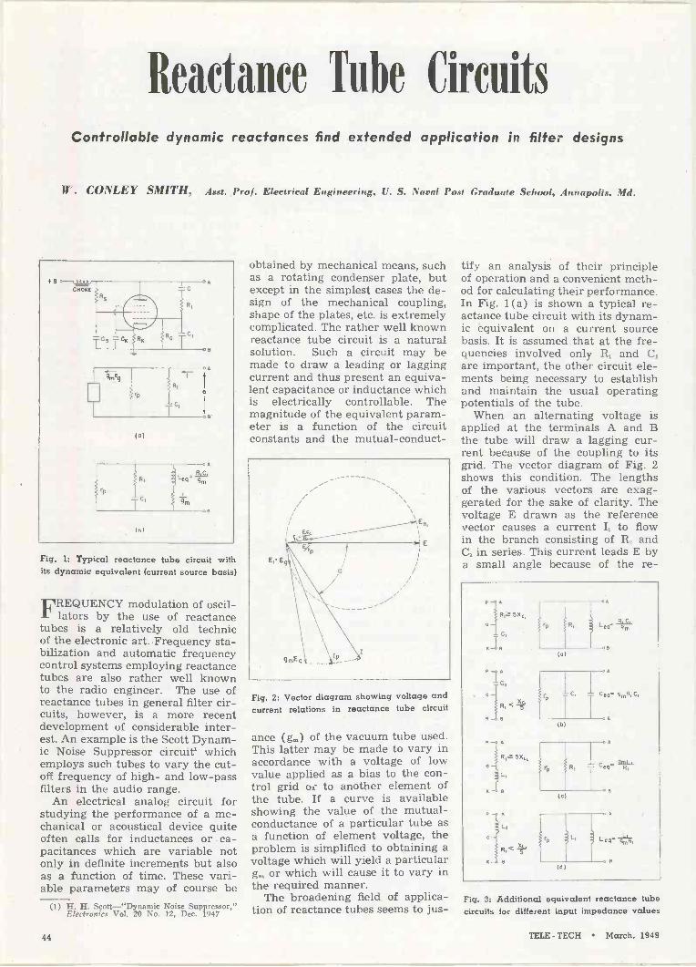
Reactance Tabe Circuits Controllable dynamic reactances find extended application in filter designs
W. CONLEY SMITH, Asst. Prof. Electrical Engineering, U. S. Naval Post Graduate School, Annapolis, Md.
Fig. 1: Typical reactance tube circuit with its dynamic equivalent (current source basis)
FREQUENCY modulation of oscil- lators by the use of reactance
tubes is a relatively old technic of the electronic art. Frequency sta- bilization and automatic frequency control systems employing reactance tubes are also rather well known to the radio engineer. The use of reactance tubes in general filter cir- cuits, however, is a more recent development of considerable inter- est. An example is the Scott Dynam- ic Noise Suppressor circuit' which employs such .tubes to vary the cut- off frequency of high- and low-pass filters in the audio range.
An electrical analog circuit for studying the performance of a me- chanical or acoustical device quite often calls for inductances or . ca- pacitances which are variable not only in definite increments but also as a function of time. These vari- able parameters may of course be
(1) H. H. Scott-"Dynamic Noise Suppressor," Electronics Vol. 20 No. 12, Dec. 1947
obtained by mechanical means, such as a rotating condenser plate, but except in the simplest cases the de- sign of the mechanical coupling, shape of the plates, etc. is extremely complicated. The rather well known reactance tube circuit is a natural solution. Such a circuit may be made to draw a leading or lagging current and thus present an equiva- lent capacitance or inductance which is electrically controllable. The magnitude of the equivalent param- eter is a function of the circuit constants and the mutual -conduct -
Fig. 2: Vector diagram showing voltage and current relations in reactance tube circuit
ance (gm) of the vacuum tube used. This latter may be made to vary in accordance with a voltage of low value applied as a bias to the con- trol grid or to another element of the tube. If a curve is available showing the value of the mutual - conductance of a particular tube as a function of element voltage, the problem is simplified to obtaining a voltage which will yield a particular g,,, or which will cause it to vary in the required manner.
The broadening field of applica- tion of reactance tubes seems to jus-
tify an analysis of their principle of operation and a convenient meth- od for calculating their performance. In Fig. 1(a) is shown a typical re- actance tube circuit with its dynam- ic equivalent on a current source basis. It is assumed that at the fre- quencies involved only R, and C, are important, the other circuit ele- ments being necessary to establish and maintain the usual operating potentials of the tube.
When an alternating voltage is applied at the terminals A and B the tube will draw a lagging cur- rent because of the coupling to its grid. The vector diagram of Fig. 2 shows this condition. The lengths of the various vectors are exag- gerated for the sake of clarity. The voltage E drawn as the reference vector causes a current I, to flow in the branch consisting of R, and C, in series. This current leads E by a small angle because of the re -
Riz 55
<
R z 5X,
Li
(c)
(b)
(c)
(a)
Fig. 3: Additional equivalent reactance tube circuits for different input impedance values
44 TELE - TECH March, 1949

O
0 a- 0 E 0
_U
2
Leg in Millihenrys .1 .2 .3 .4 .5 .7 1 2 3 4 5 7 IO 20 30 50 70 100 200
.0
\\ .\` \ \ \ \ \ 2000
Ctv . \\\ .4 \ \ \ \ \ \
\\\N\\ \ Zp'
100
\
ke 0\
ac
.. . \%\t\\\ of h 2 3 4 5 7 10 20 30 40 70 100 200 400 700 1000 2000 4000
Ceq in M icromicrofarad s
0 L E 0
2
E b
Fig. 4: Chart developed as an aid in computing the equivalent induct ance or capacitance of a reactance tube circuit from Figs. 3 (a) and (b). A similar chart can also be prepared easily for those circuits in which L, is substituted for C, as illustrated by Figs. 3 (c) and (d)
actance of C,. It develops a voltage Eg = I,Xc, which lags it by 90° as shown. This is the AC voltage on the grid which by the action of the tube sets up an equivalent current g,E. The current which the tube draws is then I = g,E0 + (E/r) added vectorially. When the current I, is added to this we have the total current I drawn by the reactance tube circuit which is seen to lag the applied voltage E by some angle O.
The circuit is not a pure equiva-
lent inductance because of the in - phase component of I. It could be made so by a more complicated coupling circuit which would throw the g,E, current vector into the third quadrant, that is lagging E by more than 90° to compensate for the in -phase component of I, + (E/r). The value of the equiv- alent inductance, and the magnitude of 0, depends upon the circuit pa- rameters as a mathematical analysis will show more clearly.
Applying Kirchhoff's current law
to the equivalent circuit 1(a) we obtain:
e e i = -+ -I- gmeg
r, R,-iXc, ieXc,
but since eg = - R, - iXc,
e e eg,Xc, i=-+ -i rD R, - iXc, Rl-iXo,
so that the admittance presented at the terminals A -B is
(Please turn to next page)
TELE - TECH March, 1949 45

REACTANCE TUBE CIRCUITS (Continued)
1 1
Yen =-+ rp Ri-i (1/wC1)
1
(1/g,a) -kw (R,C,/gm) and this is the same as for the cir- cuit of Fig. 1(b) which is therefore a valid equivalent of the reactance tube circuit.
Now if R1 is made sufficiently greater than the reactance of C1 (Say R15Xo1 as suggested by Hund2.) we may write with suffi- cient accuracy:
1 1 1
Yen=-+-+ rp R1 iw(R1C1/gm)
and the equivalent circuit becomes as in Fig. 3(a).
A similar analysis of circuits where R1 and C1 are interchanged, or where an inductance L1 is used in place of C1 yields equivalent cir- cuits as shown in Figs. 3 (b), (c), & (d). The equivalent inductance or capacitance of any of these cir- cuits may be varied by changing the mutual conductance gm of the tube. This is most easily done by varying the grid bias or by applying a con- trol voltage to another grid of the tube.
As an aid in the computation of the equivalent inductance or capac- itance of a reactance tube circuit
1 August Hund-Frequency Modulation, McGraw-Hill
the chart of Fig. 4 will be found useful. This has been drawn for use in connection with the circuits 3(a) and (b). A similar chart for circuits employing an inductance L1 could easily be made. Fig. 4 is drawn to solve either the relation Len=R,C,/gm or Cep=gmR,C1. Its use can best be shown by an example.
Suppose that an equivalent ca- pacitance of 0.01 pi is to be achieved by a circuit such as that of Fig. 3 (b) where the tube has a g,,, of approximately 6000 micromhos. After 0.01 p.f is located on the Cen scale of the chart we trace diag- onally to the intersection of the 6000 micromho line projected from the gm scale. From this point we drop vertically to the R1 scale and locate a new diagonal line which repre- sents the product R1C,. The R1 and C1 coordinates of any point on this line will satisfy the relation C, = gmR,C, for the values of C,, and gm assumed. Choosing C, = 100 p,p.f, R1 must be approximately 16,700 ohms. These values should be satis- factory for frequencies up to about 20 KC as dictated by the con- dition Xc, > SR,. It should be re- membered that the r of the tube as well as C1 are effectively in shunt across this equivalent capacitance. It is obvious that large capacitances can be realized at high frequencies only by using a tube with a large mutual conductance.
To illustrate the use of this log-
arithmic chart for a circuit such as in Fig. 3(a) let us assume that an inductance of 1 millihenry is to be achieved using a tube with a gm of 6000 micromhos. Locating 1 milli- henry on the Len scale we trace ver- tically to the intersection of the 6000 micromho line projected from the g,,, scale. This point of intersec- tion lies on a diagonal line whose coordinates satisfy the relation Len = R,C1/g0, for the values of Len and go, assumed. Choosing C, = 500 11.1,11 a value of R, = 12,000 ohms is indicated and the circuit of Figs. 3(a) or 1(a) should yield an equivalent inductance of 1 milli- henry at frequencies above about 13 KC as dictated by the re- lation R,> 5Xc,. The plate resistance r as well as R1 will be effectively in shunt across this equivalent in- ductance. Large values of equivalent inductance can be realized at low frequencies by using a tube with a low value of mutual conductance.
It is important to note that the inductance or capacitance presented by a reactance tube circuit is dy- namic rather than static, in the sense that it cannot store energy. The advantage is that the inductance or capacitance so obtained is control- lable by a voltage of low value. It should also be noted that the volt- ampere rating, or power handling capabilities of the reactance is gov- erned by the tube used, being di- rectly dependent upon its plate cur- rent rating. This factor, however, is not usually a limitation in filter ap- plications.
Ad Hoc Committee Studies Tropospheric Propagation
AT the close of the recent FCC
Engineering Conference on propagation, new rules and TV al- locations an Ad Hoc committee, made up mostly of radio consult- ants, was appointed under the chairmanship of E. W. Allen, Jr., FCC Eng. Dept. The objectives of this committee, which has met each week, were to consolidate the vari- ous views regarding subjects such as: variations in field intensity near the transmitter, due to terrain, buildings, etc.; effects of time vari- ations of the desired signal when one or more interfering signals are present; prediction of Service Field Intensities, taking into considera- tion terrain effects; and, most im- portant, extension of the FCC Prop- agation Curves to other frequen-
cies and antenna heights, especially for tropospheric propagation.
The committee has agreed not to discuss Synchronized Carriers. While hoping that this will be a practical help, it apparently will not be used in the new allocation plan. The previously -employed ra- tios of desired -to -undesired signal, (100, to 1 for co -channel operation, 2 to 1 for adjacent channel) will not be changed.
Why are the conclusions reached by this committee of importance to the U. S. television industry? The short-term reason is that Chairman Coy says the lifting of the "freeze" on new applications waits upon the final report of the committee. The more important long-term reason is that a successful national television
service in the future depends large- ly on station allocation being based on sound propagation knowledge. Otherwise our programs in our homes will be spoiled by interference from undesired stations when more stations are transmitting and transmitter pow- er is increased. Co -channel interfer- ence is already serious in some areas, even with station spacing of 90 to 150' miles. The ground - wave range of a station is predict- able, but the more erratic trans- mission due to the troposphere may give fairly strong signals at dis- tances of several times the line -of - sight range and it is such transmis- sion that the Ad Hoc committee is attempting to scientifically evalu- ate. So many variables effect tropo- spheric propagation that no com- plete theory has been evolved yet and field strength measurements have not been made on a sufficient number of frequencies, nor over a
(Continued on page 74)
48 TELE - TECH March. 1949

IA
"Electrontype" Speeds Communication
"Charactron," new type cathode ray tube, can repro-
duce printed messages at a million word per minute rate
AN ultra -high-speed electronic unit for use in the transfer of
messages and data has reached the development stage and is expected to replace many current methods of sending and recording printed material. Equipment can be de- signed to produce messages in printed form at the rate of one million words per minute, accord- ing to J. T. Meaney of Consolidated Vultee Aircraft Corporation, its designer.
The operating principles of one type of Charactron can be repre- sented as a type of cathode ray tube equipped with means by which the ray is converted into shapes of predetermined characters, by a character -shadowing disc in the path of the beam. The cross section of the electron beam conforms to shapes of aperture configurations in this disc when directed through the individual openings. Electron shad- ows of these characters can then be selectively focused on fluorescent viewing screens.
The individual character open- ings in the disc, arranged vertically in a line, each have respective shapes and quantity depending on the intended application. Any char- acter is selected for presentation by means of a voltage applied to a pair of selector plates. After the beam is directed through an open- ing in the disc, its cross section will be representative of a message character, which by the H. and V. deflection plates can be directed to any part of the screen.
In the enlarged portion of the de- flector assembly shown, characters "C, D, and E" represent typical openings in the shadow disc. Each vertical plate is common to two in- dividual characters, while the hor- izontal plates are common to all characters. Thus a series of input signal potentials will produce lines of information on the viewing screen. Such a screen, 8 -in. in diam- eter, could accommodate 60 or more lines, or approximately 150 words. Presentations of this type are in -
One version of a complete electrontype re- corder which displays single line of symbols with space provisions for 70 symbols per line
tended for either projection on larger screens or for recording pur- poses but increasing the size of characters (and reducing the lines) permits messages to be read direct- ly from the fluorescent screen. The application will determine if other types of displays are more suitable. The size of characters to be used, and the persistence of the screen can also be modified.
70 Symbols per Line
One version of a complete Elec- trontype recorder is shown which displays a single line of symbols, with space provisions for 70 per line. A short persistence fluorescent screen is provided 71/2 -in. in length and 3/16 -in. in height.
Provisions within the tube allow for a selection from 40 different characters the letters of the alpha- bet, digits 1 to 9, and various punc- tuation marks. Introducing other characters does not necessarily pre- sent a problem. Several hundred may be incorporated in a tube, and it is not necessary that they be ar- ranged in a single straight line as indicated. Viewing the apertures in
the shadowing disc from the face of the present tube, they are lined up at right angles to the rectangu- lar -shaped screen.
Other major units of the complete recorder include: servo -controlled film supply and film take-up mech- anisms, film synchronizing circuits and control mechanisms, lens sys- tem, input selector and sweep con- trol circuits and the usual power supplies.
Information is taken from the coded signals unit and coupled to control circuits and frequency di- vider units. The coded signals unit can represent a data memory de- vice, or a radio receiver of coded intelligence. Output from control circuits is coupled to selector plates and vertical deflection plates. Sig- nals from frequency dividers are coupled to sweep circuits and motor synchronizing circuits. Potentials from the sweep circuits control the start and completion of each line in accordance with the rate of re- ceived characters.
For the purpose of keeping iner- tia effects of large rolls of film iso- lated from film synchronizing mechanisms, servos are employed in film supply and film take-up sys- tems. The lens system between the film and Charactron screen gives (for 35 -mm film) a 5 to 1 reduction in the optical system. Exposures do not exceed 1 mm in height, nor 0.5 mm in width.
With 70 exposures per line, when using 35 -mm film, it is possible to expose 10,000 characters on 150 mm of film. At input signal speeds of 20,000 characters per second, for instance, the film will only be trav- eling through the printer at approx- imately 300 mm per second.
Electrontype recorders can be standard for application of many different varieties. Details of the unit identified as coded signals, however, will vary somewhat. It is well within the realm of sound rea- soning to assume that if it is pos- sible to put information into code form, equipment designed around the Charactron may be able to print faster than any other conceivable method.
The Charactron and its applica- tion to high-speed signaling was invented by the author, who has obtained United States patents on important features. Until recently, the invention was ahead of certain arts in cathode ray tube develop- ment and photography. There no longer appears to be any real ob- stacles in the way of broad appli- cations of these principles.
TELE - TECH March, 1949 47

NAB Engineering Conference, Chicago, Apr. 6-9
Dr. William' L. Everitt, head of the University of Illinois department of electrical engineering, will be the prin- cipal speaker at the National Associa- tion of Broadcasters' Engineering Con- ference held at the Stevens Hotel, Chi- cago, April 6-9.
Dr. Everitt, whose acceptance of the invitation to addréss the engineering conference was announced by Royal V. Howard, NAB Engineering Department director, will be heard at the luncheon on Thursday, Apr. 7.
"We are proud and pleased to have Dr. Everitt's acceptance," Dr. Howard said. "He will be remembered by all engineers as a past president of the Institute of Radio Engineers, and as having conducted the famous broadcast engineering conferences held at Ohio State University."
During the late war, Dr. Everitt was director of the operational research staff, office of the Chief Signal Officer, U. S. Army. He was given the Excep- tionally Meritorious Civilian Award for this and other wartime engineering work.
Registration will begin on Tuesday, Apr. 6, and a tour of a radio factory in the Chicago area is being arranged for the afternoon, with a party to follow in the evening.
Technical papers, to be presented by outstanding radio engineers will oc- cupyThursday and Friday, Apr. 7 and 8, and a half day of activity is being arranged for the Conference's final day.
The technical papers will cover all aspects of radio engineering, on a prac- tical and theoretical level, about half of them being devoted to television. Other subjects to be discussed will in- clude magnetic recording, NAB record- ing and reproducing standards, and the problems of AM and FM radio.
In addition to the formal meetings of the Conference, the largest exhibit of radio and television equipment and services in NAB convention history will open Thursday, Apr. 7.
FMA at New York, April 1 The FM Association has hired a new
executive director at its Washington office and outlined an expanded pro- gram for 1949, with special emphasis on programming, time sales and agency relations. As executive director, FM Association has appointed Edward L. Sellers, an ex -Navy aviator who has been radio editor and sales representa- tive for the Associated Press, Washing- ton city news report for the past 17 months.
To assist in establishing and execut- ing the expanded operating program for 1949, the association has retained the Faught Co., New York City, as public relations counsel. FMA's head- quarters will be retained at Washing-
ton, D. C., and bulletin service to the members will be expanded, largely with "how -to -do -it" case material in tackling problems most common to FM stations.
In addition to its annual convention in Chicago, the association is planning an "FM Time Sales Clinic" on April 1 in New York City.
IRE-RMA Meet April 25-2 7 Some of the newest technical de-
velopments in the radio -television in- dustry will be discussed at the annual spring meeting of the RMA Engineer- ing Department and the IRE April 25- 27 at the Benjamin Franklin Hotel in Philadelphia.
Technical sessions will occupy the mornings of the three-day conference of radio engineers, and RMA and IRE committee meetings and inspection trips will occupy the afternoons, ac- cording to details of the program re- leased by Virgil M. Graham, chairman of the committee in charge. Technical papers which will be presented are: "A Three Kilowatt Medium Frequency Transmitter Utilizing Iron Core Interstage and Output Circuits"
L. F. Deise and L. W. Gregory, Westinghouse Electric Corp.
"The Use of the Cavity Resonator in the Mobile Communications Field"
Henry Magnuski, Motorola Inc. "The Symmetron 50 Kilowatt FM Broadcast Ampli- fier"
L. D. Balthis, Westinghouse Electric Corp. "An Instantaneous Deviation Control for Phase Modulation Transmitters"
Marion Winkler, Motorola, Inc. "Television Recording Technique"
R. V. Little, Jr., Radio Corporation of America "The Utiliscope, Pioneer of Industrial Television Systems"
M. Cawein and J. A. Good, Farnsworth Television & Radio Corp.
"A New Television Visual Modulator" A. J. W. Rhodehamel, General Electric Company
"The Reality of Invisible Forces" E. Finley Carter, Sylvania Electric Products Inc. "High -Efficiency Coolers for Forced -Air -Cooled Pow-
er Tubes" M. B. Lemeshka and A. G. Nekut, Radio Corpora- tion of America
"Audio Power Amplifier with Positive and Negative Feetback"
John M. Miller, Jr., Bendix Radio "Longitudional Interference in Audio Circuits"
H. W. Augustadt, Bell Telephone Laboratories "Commercial PTM Telephone Microwave Link"
N. J. Gottfried, Federal Telecommunication Lab- oratories W. J. Logan, Maritime Telephone & Telegraph Company
National Telemetering Forum A new telemetering society, the Na-
tional Telemetering Forum, has been organized for the purpose of develop- ing telemetering. All organizations hav- ing a bona fide interest in telemetering are cordially invited to send repre- sentatives to the meetings of the Na- tional Telemetering Forum, and to participate otherwise in its activities.
The chairman is W. J. Mayo -Wells, Applied Physics Laboratory, Johns Hopkins Univ., 8621 Georgia Ave., Sil- ver Spring, Md. Meetings are held once every six weeks at different plants, a recent session having been scheduled at the factory of Melpar, Inc., 452 Swann Ave., Alexandria, Va.
Navy Host to AFCA, March 28-29
With the Navy as the host organiza- tion for this year's annual convention of the Armed Forces Communications Association, Washington, D. C., Ad- miral Louis Denfeld, Chief of Naval -
Operations, is slated to deliver a feat- ure address at the annual AFCA ban- quet Monday, March 28
The AFCA convention headquarters will be the Shoreham Hotel in Wash- ington. On the second day of the con- vention, those attending the meeting will visit exhibits and demonstrations planned and directed by the Navy at its stations and aboard ships in the Washington area. The business meet- ings will be held March 28 at the Shoreham.
Since the unification of the armed services, it has been AFCA's policy to rotate the location and host service of the annual affair. The first con- vention, in 1946, was staged at the Sig- nal Corps center at Fort Monmouth, N. J., and in New York City, while last year's meeting had the Air Force as host at Dayton, O., and the Wright - Patterson Air Force Base.
Coming Events
March 7-10-IRE Annual Convention, Hotel Commodore and Grand Central Palace, New York, N. Y.
March 14-17-Illinois Seventh Chicago Production Show, sponsored by Chi- cago Technical Societies Council, Stevens Hotel, Chicago.
April 6-9 - National Association of Broadcasters, Engineering Confer- ence, Hotel Stevens, Chicago.
April 11 -12 --Conference on Industrial Use of Electron Tubes, American In- stitute of Electrical Engineers, Stat- ler Hotel, Buffalo, N. Y.
April 18-20-Midwest Power Confer- ence, sponsored by Illinois Institute of Technology, Sherman Hotel, Chi- cago, Ill.
April 19-21- American Institute . of Electrical Engineers, South West Dis- trict Meeting, Baker Hotel, Dallas, Texas.
April 25-27 -Fourth Annual Spring Meeting of IRE and RMA, Benjamin Franklin Hotel, Philadelphia, Pa.
May 2-4-International Scientific Ra- dio Union and IRE, Joint Meeting, East Bldg. Lecture Room, National Burean of Standards, Washington, D. C.
May 16-19-RMA and Radio Parts Show, Hotel Stevens, Chicago, Ill. RMA 25th Anniversary.
June 20-25 - American Institute of Electrical Engineers, Summer Gen- eral Meeting, Swampscott, Mass.
48 TELE - TECH March, 1949

NEW NAMES AND ADDRESSES George Miller has resigned as chief
engineer of Televista Corp. of America to enter his own development and manufacturing company with offices and labs at 94 Holland Ave., Elmont, L. I., New York.
* * *
William A. Gray, formerly with Raytheon Mfg. Co. has established a management consulting service at Middlesex Road, Watertown, Mass., planned for the electronic equipment and tube industry, and covering the functions of organization, product pro- motion and Government programs.
* * *
W. T. LaRose & Assoc., Inc., manu- facturers of "Thermall" electronic heating equipment have moved their entire manufacturing plant to new and larger quarters at 31 Ontario St., Co - hoes, N. Y. This new location is only one mile from their previous address in Troy.
Bell Files New Tariffs New tariffs have been filed by the
American Telephone & Telegraph Co. with the FCC, effective March 1, to clarify and amplify the provisions under which the company furnishes channels for television transmission. These filings are based on experience in providing service in recent months and are in line with statements made by the company during the television rate hearing before the FCC. Similar tariffs were also filed by the New Eng- land Telephone & Telegraph Co. to illustrate the type of tariff which will be filed by other Associated Com- panies of the Bell System, to become effective on the same date. The chief changes in the tariffs are: A) The present tariff includes o provision that the A. T. & T. Company will not interconnect its inter- city television network facilities with the inter -city facilities of other companies, except in areas where the Telephone Company does not have such net- work facilities available. In the new filing, the conditions under which inter -city channels of other companies may be connected with Bell System inter -city channels are further clarified. The provi- sions fall into two categories:
1. Where the customer requires television network service for less than three months (usually for particular events and not for con- tinual use), and if the telephone company does not hove facilities, the inter -city channels of other companies may be interconnected with telephone company inter -city channels for vary- ing periods up to three months - or until telephone company facilities are available. This depends upon the particular circumstances involved.
2. Where the customer requires television network service for more than three months' duration, and if the telephone company cannot within twelve months extend its facilities to the customer's location, the inter -city channels of other companies may be connected to Bell System inter -city channels for thirty-six months - or longer, if the telephone company does not then have facilities.
In both the above cases, the tariff provisions stipulate reasonable notice from and to customers as well os the periods of inter -connection. B) Where available inter -city channels are insuf- ficient to care for the requirements of all monthly service customers, usage will be allocated on a quarterly basis. This assures broadcasters the use of the channels for a longer period than the present 30 days, and thus should facilitate their selling network time to advertisers. C) The areas in which local channel rates of the Bell System apply between television broadcasting stations are in general enlarged and made more uniform by including channels where the telephone exchanges serving the television customers are not more thon twenty-five miles apart. As under the present tariff provisions, Bell System customers may use non -telephone company channels within these new areas and connect such facilities with the inter -city and local television networks of the Bell System on on unrestricted basis.
U. S. Radio Stations and Operators
(as of December 31, 1948 -FCC) Broadcast Stations
AM 2,127 FM 966 TV 124 Experimental TV 182 Educational 50 Facsimile 2 International 37 Remote pickup 574 Other 40
Total 4,102 Nonbroadcast Stations
Aeronautical 25,716 Marine 18,256 Public Safety 5,316 Industrial 3,661 Land Transportation 3,506 Amateur 77,338 Miscellaneous **1,747
Total 135,540 Radio Operators
Commercial *366,000 Amateur 76,666 Special aircraft
authorizations 94,752
Total 537,418
*Estimated. **Includes authorizations in the Common Carrier Services. (1,101 as of Dec. 31, 1948.1
New Oscillograph Service The engineering development and
model shop facilities of the instrument division of Allen B. Du Mort Labora- tories, Inc., are now available and are offered to the industry for the devel- opment, design and construction of special cathode-ray instruments. Es- tablishment of this service is the re-
sult of an increasing demand for spe- cial equipment and for special modifi- cations of catalog items. Recognizing the importance of special instruments to the advancement of the art of cathode-ray oscillography, the com- pany has made its engineering design services and Model Shop facilities available for such work. Write to Allen B: Du Mont Laboratories, Inc., Instrument Division, 1000 Main Ave- nue, Clifton, New Jersey.
Broadened Tube Standards The American Standards Associa-
tion Sectional Committee on Electron Tubes C-60, formerly sponsored by the Electrical Standards Committee, is now sponsored by the Joint Electron Tube Engineering Cour pil, according to Virgil M. Graham, chairman of the Council and director of technical re- lations for Sylvania Electric Products, Inc.
The committee is being reorganized and its scope is being broadened to include definitions; classifications; methods of rating and testing; dimen- sions and interchangeability of elec- tron tubes for all applications. The former committee concerned itself only with electron tubes for industrial use.
The new committee will include representatives of the American As- sociation of Electrical Engineers, the American Association of Railroads, Electric Light and Power Group; the IRE; the Joint Electron Tube Engi- neering Council; the National Bureau of Standards; the National Electrical Manufacturers Association; the Radio Manufacturers Association; Telephone Group; the Army -Navy Electronic Engineering Agency, and liaison from the Canadian Standards Association.
O. W. Pike of the Electronics De- partment of the General Electric Com- pany has been appointed chairman of the reorganized Committee.
OPERATING SCHEMATIC OF TELEVISION RECEIVER
Resembling a giant operating schematic, the RCA Dynamic Demonstrator has every com- ponent and circuit of a conventional home television receiver mounted on a 31/2 by 51/2 ft. board. John Meagher, Tube Dept. specialist designer of the Demonstrator, is shown with the new unit which will aid the training of engineers and servicemen in TV troubleshooting
TELE - TECH March, 1949 49

WASHINGTON zecee .ze,eret egefif tilf4
Latest Radio and Communications News Developments Summarized by Tele-Tech's Washington Bureau
TELEVISION ENGINEERING STANDARDS IN MARCH-Most important development for television in Washington will be the issuance by the FCC of its analysis of the engineering report by the joint industry - Commission "Ad Hoc" committee on propagation, ground wave and tropospheric interference subjects in the VHF portion of the spectrum, and the new Commission tele- vision and FM broadcasting engineering standards. This report, given intensive analysis and summarization dur- ing latter part of February by FCC Technical Division, is slated for publication early in March. The committee is composed of the topflight radio engineering execu- tives of the IRE and RMA and the conference group has been headed by Edward W. Allen, chief of the FCC Technical (Engineering) Information Division. This timetable indicates that the FCC freeze on video applica- tions may be lifted between April and June and Com- mission Chairman Coy's hope of UHF television chan- nels being opened before the end of 1949.
SENATE SUBCOMMITTEE REPORT MEANS POSTPONING FCC PANEL PLAN-The plan of the Federal Communications Commission to divide into three panels or divisions in its major fields of regulation -broadcasting, common carrier communications, and mobile safety and special radio services-now has to be shelved or maybe even discarded as the result of a highly critical report on the proposal from the com- munications subcommittee of the Senate Interstate and Foreign Commerce Committee. The Senate Committee, of course, has jurisdiction in the Senate over radio and communications legislation and its words are most weighty when it comes to FCC.
WOULD NEED SPECIAL CONGRESSIONAL AC- TION-The Senate subcommittee report, filed by Senators McFarland (D., Ariz.) and Tobey (R., N. H.), which received the approval of Chairman Johnson of the Committee, expressed the view that the panel system had weakness in the quasi-judicial procedure of regu- lation and actually could not be put into operation by the FCC without special Congressional legislation. To expedite the FCC's work load of applications and cases, the Senate subcommittee recommended that a system of legal officials apart from the regular law staff be instituted along the lines of examiners and that the Law,. Engineering and Accounting Departments of the FCC be functionalized along the lines of the Commission's workload. In both the latter instances the FCC has been organized in this functionalized setup both under former Chairman Denny, now NBC Executive Vice President, and the present Chairman Wayne Coy..
NATION'S RADIO MANUFACTURERS AGREE ON MOBILIZATION PLANS-Nation's electronic -radio manufacturing industry and laboratories have com- pleted their "make-ready" plans for the increased re- quirements of the military services under the present national defense preparedness program and for mush- roomed growth for any war emergency. This was ac- complished at the Feb. 16 meeting of the 29 -member Electronics Equipment Manufacturing Industry Advi- sory Committee with the Munitions Board and National Security Resources Board that evolved an overall mobilization plan for equipment and parts production and research activities.
A. T. & T. TARIFF CHANGES AID BROAD- CASTERS-In line with discussions at the recently - concluded FCC hearing on the A. T. & T.'s ban on interconnecting its intercity television links with those of others where telephone company facilities are avail- able, the A. T. & T. has revised its tariffs to protect tele- casters who build their own intercity relay systems. The tariff change is that when a telecaster in an area not served by the Bell System TV network requires service for a period of more than three months, and the A. T. & T. does not foresee extending its own links to the telecaster's city within a year, the latter can inter- connect any relay he might build with the Bell System facilities for three years. Heretofore, the telecaster could not have interconnected with the telephone company links after they became available. Thus, the new tariff affords opportunity for a three-year amortization of the private system.
POLYCASTING BY WILMOTTE-In the January "Washington News Letter's" first item on the deep interest which television has stimulated in Washington officialdom, there was an editorial error in stating that FCC Chairman Coy had publicly commended "poly - casting in the UHF band' of TV as developed by RCA." The correct reporting of Chairman Coy's remarks be- fore the Television Broadcasters Association should have brought out that the FCC chieftain had com- mended both "polycasting" as developed by Raymond Wilmotte, a leading radio engineer, and "TV carrier synchronization" as developed by RCA, which are both excellent methods for extending UHF television. The RCA method had been tested very successfully by the NBC ultra -high -frequency video station WNBW in Washington. Mr. Coy also cited in his address Westing- house's "stratovision" as a medium for the relaying of television programs and increasing coverage beyond the" horizon areas.
ROLAND C. DAVIES National Press Building Washington Editor
50 TELE - TECH March, 1949

There's a Beckman POTentiometer) (Trade Mark of the HELlcal
el Ot to simplify YOUR Potentiometer-Rheostat Problems!
CUTAWAY VIEWS)
MODEL B -Case diameter -3.3"; Number of turns -1S; Slide wire length -1401/2"; Rotation -5100°; Power rating -10 watts; Resistance ratings -50 to 300,000 ohms.
HELIPOT'S Wide -Range, High -Precision Control Advantages Available in Many Sizes of Units
FI e Ii p o t -the original helical potentiometer- has proved so popular in modern-
izing and simplifying the control of electronic cir- cuits, that many types and sizes of Helipots have been developed to meet various potentiometer -rheo- stat problems. Typical production Helipot units include the following...
MODEL A Case diameter -1.8"; Number of turns -10; Slide wire length - 46%"; Rotation - 3600° ;
Power rating-S 'watts; Resistance ratings -10 to 100,000 ohms.
FEATURES
WIDE CHOICE OF DESIIGN
e
Not only ore Helipots available in a aside
range of sites and ratings,but lso
supplied with various design features to
requirements screw meet in1
shafts, batted shafts,
with special lengthend to permit
+ gvoilable each
driver slots, lied with shaft extensions devices. three
Can be instruments or
ganged assembles of two or
coupling to indicating May be provided
in 9 shat' and even less. it
all operating from a common O.1%-and
Available with linearity tolerances of additional taps
' available B can be modified to ia.:lude
' Models yA point on windings other special features. gained by
at virtually and many advantages to
important a control be gained by
ate the many electronic Investigate of in your wing the IíetP
our prublrm! W ite outlining y
Have you latest data on DUODIAL-The turns -
indicating knob dial? It not, write!
MODEL C-Case diameter -1.8"; Number of turns -3; Slide wire length -' 13.5"; Rotation - 1080° ;
Power rating -3 watts; Resistance ratings -5 to 30,000 ohms.
SPECIAL MODELS
In addition to the above standard Helipot units, special models
in production include . , ,
MODEL D-Similar to Model B, above, but longer and with greater
length of slide wire. Case diameter -3.3"; Number of turns -25; Slide wire length -234"; Rotation -90000; Power rating -15 watts;
Resistance ratings -100 to 500,000 ohms.
MODEL E-Similar to Model B, but longer and with greater length
of slide wire than Model D. Case diameter -3.3"; Number of turns -40; Slide wire length -373"; Rotation -14,4000; Power rating - 20 watts; Resistance ratings -150 to 800,000 ohms.
Send for HELIPOT Literature!
THE HeliP otcORPORATION SOUTH PASADENA 3, CALIFORNIA
TELE TECH March, 1949 51

TV 8z Communications Components Television Tuner
A unique combination of inductance and ca- pacity variation is featured in model TF 701, a new television front end tuner. This unit
tunes continuously over twelve channels with substantially constant bandwidth. Frequency gaps between channels are bridged in one smooth motion, so that a 180° rotation of the tuning device covers all channels. The unit contains conventional rf amplifier, oscillator and mixer circuits and comes complete with lighted dial and planetary reduction drive. -- Vision Research Laboratories, Inc., 87-50 Lefferts Blvd., Richmond Hill, N. Y.
Remote Control Unit Turning on the plate power at the transmit- ter or silencing a particular combination of station receivers are two of the functions per-
formed by the EC -8-A, a new remote control unit. It employs an automatic level control preamplifier to modulate the transmitter and to maintain the maximum allowable signal. There are two separately controlled inputs to the line amplifier circuit: one for station re- ceiver monitoring; another for monitoring auxiliary receivers.-General Electric Corp., Syracuse, N. Y.
TV Camera Pedestal Capable of rolling smoothly and silently on
3 rubber -tired wheels, the '11D -1A studio camera pedestal provides a convenient and
useful mounting for the television camera in the studio or other indoor telecast locations. A crank handle raises or lowers the camera between 40 and 60 in. above the floor. The crane boom on which the camera is mounted can be raised to a height of 74 in. or lowered to 23 in. above the floor.-RCA Victor Div., Radio Corporation of America, Camden. N. J.
TV Distributing System A simple low-cost solution to the problem
of satisfactorily operating a number of tele- vision sets from one antenna is offered by the Multivideo Connector, a unit which oper- ates like a bridging transformer picking up a signal through the insulation of ordinary twin - lead feed -line. One Multivideo Connector is required for each receiver using the same an- tenna. Connectors are about 80% efficient and give satisfactory coupling so long as there is a 20% reserve of signal in the an- tenna system. As many as thirty receivers have been operated in a system without mu- tual interference or cumulative signal loss.- Reeves Sounderaft Corp., 10 East 52nd St., New York 22, N. Y.
FM Carrier Telegraph Operation of the model 22 FM or carrier shift telegraph system is free of interference
on 18 60 -word -per -min. channels between 420
or 2460 cps or 12 75 -wpm channels between 425 and 2039 cps. Transmitter, receiver (il- lustr.), and relays are mounted in separate panels. Multi -section networks incorporating toroidal coils wound on molded iron -powder cores are utilized for filter sharpness. All com- ponents are derated, plug-in relays are used throughout, and circuits are designed to use industrial type tubes.-Lenkurt Electric Co., 1109 County Road, San Carlos, Calif. Television Tuner
The Guthman Super Q Television Tuner, an all channel selector, can be mounted ver-
tically or horizontally on a receiver chassis. It has tuned transformer input and no double conversion effects. There is a high fre- quency switch control and a seperate vernier for fine tuning. The design of the unit makes it easily accessible for servicing.-Edwin I. Guthman & Co., 15 S. Troop St., Chicago 7, nl. VHF -FM Receiver
Dual tuned circuits with extremely high "Q" are used throughout model 389-R VHF - FM receiver, a crystal -controlled, fixed -fre-
quency, superheterodyne unit designed for single channel reception. Unlike most 152-162 MC FM receivers, the 389-R utilizes single conversion with resultant circuit simplifica- tion and reduction of spurious responses. All but one circuit are capacitor tuned. Chassis is mounted behind a 19 -in. relay rack panel, 514 in. hgh.-Communications Co., Inc., 300 Greco Ave., Coral Gables, Florida.
TV Chassis A television receiver which can use a 10
or 12 -in. tube has been designed for custom installation and is supplied complete with
speaker and all tubes (less picture tube). Known as model T-64, it comes in two units: a main receiver chassis and a power supply chassis. Dual focusing provides larger size pictures on the same size tube without aban- doning absolute linearity of proportion be- tween width and height. The unit has 19 tubes and 3 rectifiers, not counting picture tube.-Hallicrafters Co., 4401 Fifth Ave., Chi- cago, III.
Power Supply Model 252, regulated DC power supply has
an output adjustable from 2,60 to 300 volts DC, negative grounded. Input requirements
are: 115 volte, 60 cycles, 4,00 watts. With load changes from 400 to 6.00 milliamps., the output voltage change at any setting Is less than 0.05%, varying between individual units from 0.015% to 0.04%. Equal stability ex- ists with respect to minor line voltage changes. Noise level is less than 0.001%.- Beta Electronics Co., 1762 Third Ave., New York 29, N. Y.
Isolation Trans folnur An air insulated isolation transformer has been developed for supplying 60 -cycle light-
ing voltages to antenna tower lighting cir-
cuits without providing an 11F path to ground. Paralleling the unit across a tower base only produces a negligible change in the base im- pedance of the tower because RF impedance is so great, due to an interwinding air gap. A ball gap lightning arrestor is provided to protect the unit from lightning damage.- Andrew Corp., 363 East 75th St., Chicago 19, Ill.
52 TELE - TECH March. 1949

New Tubes
Miniature Pentode Type 6AN5 is a new miniature pentode
(left in illustr.) which may be used in many of the applications for which the metal tube 6AG7 was previously used. In addition, it is
useful at the very high frequencies as a fre- quency multiplier, wide band RF an IF am- plifier, class C RF amplifier, and switching tube for computers. The 6AN5 has a normal plate current rating of 35 MA and a trans - conductance of 8,000 µmhos. Type of CK- 5654 (right in illustr.) meets Bureau of Ships specifications and was developed specially for aircraft equipment applications where the standard type 6AK5 had not proved suffici- ently dependable. The heater is designed to withstand at least 5,000 on and off cycles at 7.5 volts, and special care is given in produc- tion to insure a tube of the highest quality, best performance and longest possible life.- Raytheon Mfg. Co., -60 East 42nd St., New York 17, N. Y.
Power Triodes Four new power triodes have been developed
with plate dissipations ranging from 0.6 KW to 50 KW. The 5786 (upper left) which is designed for industrial and broadcast service is an improved version of the type 6-C24, per- mitting use with a low-cost blower. It has a maximum plate dissipation of 600 watts. Model 5771 (upper right) has a maximum plate dissipation of 2!2.5 kilowatts and a thori- ated tungsten filament for high emission cap- ability facilitates a saving of almost 70% in filament power. It has a. maximum filament
starting current 4.7 times higher than the filament operating current, thus permitting operation without a filament starter. The 5762 (lower left) is a thoriated-tungsten- filament type of forced -air-cooled, grounded -
,grid power triode designed for FM broadcast and industrial services. It has a maximum plate dissipation of 2.5 KW, and can be oper- ated with full plate voltage and plate input up to 110 MC. Type 5770 is a power triode with a maximum plate dissipation of 50 KW. A strong, cylindrical copper grid support pro- tects the grid from electron bombardment and radiated filament power as well as pro- viding low grid inductance, low plate -filament capacitance, and effective RF shielding be- tween plate and filament in grounded -grid cir- cuits-Tube Dept., RCA Victor Div., Radio Corporation of America, Harrison, N. J.
"I DID IT .
wme I DID IT!"
The hen gives herself a good round of
applause every time she lays an egg.
And well she might - but she couldn't have done it without that little bit of
calcium which forms the shell.
Every time a top engineer sees one of
his drawing board dreams breaking a
speed or endurance record, he says to
himself, "I did it - did it - did it!" - and that does not mean he has laid
an egg, either.
But that dream could not have materi-
alized - not good - without that little
bit of so-essential Mica. And not real
good - if that Mica wasn't Macallen.
MACALLEN MICA ALL FORMS, ALL QUANTITIES - ALL DEPENDABLE
when you think of MICA, think of MACALLEN
THE MACALLEN COMPANY 16 MACALLEN ST., BOSTON 11, MASS.
CHICAGO. 565 W. WASHINGTON BLVD. CLEVELAND: 1231 SUPERIOR AVE*
TELE - TECH March, 1949 53

Sound Equipment
READ NOISE FIGURE DIRECTLY WITH THE
MEGA -NODE (NOise dioDE)
A Calibrated Random Noise Source
HELPS OVERCOME RF FRONT END PROBLEMS
Extend the range of your high frequency receiver (TV, FM, Radar) by reducing noise. The MEGA -NODE provides a simple method of determining the noise figure. Read the noise figure in db directly from a meter.
Indicating meter reads db on a linear scale. Choice of several output impedances. Output contains negligible hum.
Uses: Laboratory, production line testing, development of TV, FM, Radar and other high frequency receivers.
SPECIFICATIONS Frequency Range: 1 to 220 me
Output Impedances: 50, 70, 100, 150, 300, ohms and infinity controlled by panel switch.
Noise Figure Range: O to 17 db at 50 ohms 0 to 23 db of 300 ohms
Filament Voltage: Regulated d.c. used on filament of noise generating tube. Power Supply: 117±8 volts 60 cps Dimensions: 8" x 16" x 8"
Price $295.00 F.O.B. Factory
KAY ELECTRIC COMPANY 23 MAPLE AVENUE, PINE BROOK, NEW JERSEY
CALDWELL 6-4000
Mega -Sweep Mega -Marker Mega -Marker Sr. Kay Sound Spectrograph
MANUFACTURERS OF Megaligner Mego -Match Megalyzer Mego -Match Mega -Pulser
Megalyzer Mego-Pipper Megalyzer Jr. Micro -Pulser
SEE THESE INSTRUMENTS AT BOOTH 22 IRE CONVENTION
LP & Standard Reproducers Models 153 M and R reproducers have been
designed for long-playing microgroove records and regular standard recordings. Micro-
groove recording reproducer (model M) con- sists of playing arm, head piece, cartridge, rest, and compensating network with four position switch. Components of model R are identical but unit is designated for standard lateral recordings. The compensator network and switch provide proper characteristics for reproducing flat recordings. T8 rpm phono records, NAB recordings, and recordings re- quiring a large roll off at the high end. The frequency response of the compensator in the various equalizer positions is practically un- affected by the value of the terminating load impedance over a range of 100 ohms to high impedance.-Presto Recording Corp., P. 0. Box 500, Hackensack, N. J.
Magnetic Tape Recorder A completely new type of recording mechan-
ism, and a compact high gain amplifier unit are two features of the Crestwood Magic Tape
Recorder which faithfully reproduces the full frequency range from 50 to 8000 cycles. The two -channel recording system will transcribe a full hour of recording on a standard half- hour reel. In addition, the machine will also play single channel recordings made on other machines. Rewind time is less than 1'k min- utes for the half-hour reel. Automatic eras- ing device has a safety control that prevents accidental erasing while rewinding tape.- Crestwood Recorder Corp., 218 S. Wabash Ave., Chicago 4, Hl.
Cueing Amplifier A new cueing amplifier for transcription
turntables provides a local audio signal suit- able for monitoring or cueing. Known as the
635-A S, it uses pushpull stages and in- verse feedback and will supply 3 watts of au- dio to a loudspeaker. Frequency response is from 70 to 15,000 cps, ± 1 db. Various voice coil impedances are available and a high im- pedance output is provided for feeding one or more headsets. A transformer input of 10,000 ohms impedance permits grounded or ungrounded bridging across any low imped- ance line without reflecting a mismatch.- Fairchild Recording & Equipment Corp., 154th St. & 7th Ave., Whitestone, N. T.
54 TELE - TECH March, 1949

Noise Suppressor Amplifier New changes in the output transformer and
chassis finish of model 210-A laboratory am- plifier with dynamic noise suppressor hn
suited in substantial improvements in per- formance, without sacrificing any of the com- pactness and fine design that characterize the unit. The oversize output transformer pro- vides freedom from distortion and reduces hum level to 86 DB below maximum power output under normal operating conditions. Actual hum power level is only 0.05 micro- watt.-Hermon Hosmer Scott, Inc.. 385 Put- nam Ave., Cambridge Mass.
Auxiliary Speaker As many as eight Ad -A -Vox auxiliary
speakers can be connected to the standard radio set, television receiver, phonograph or amplifier, without altering normal operation and sound quality. Each one of these new units is fully enclosed in a non -breakable cast -aluminum case and contains a quality 4 -in. permanent -magnet speaker with volume control.-Tarrytown Metalcraft Corp., 82 Chestnut St., Tarrytown, N. Y.
Tone Arm The cartridge of the new Trionic arm for
transcriptions and records can be quickly replaced without soldering and no adjustment
of needle force is necessary . A quick -acting weight adjustment makes possible any needle force from 5 grams up. The arm will ac- commodate any pickup cartridge, magnetic or crystal, not over 7a in. wide. Available in 2 sizes, the Trionic can be used with 12 -in. records and 16 or 1 -in transcriptions and acetates.-Clarkston Corp., 11927 West Pico Blvd., Los Angeles 34, Calif.
Portable Sound System An acoustical output equivalent to that of
a 30 -watt portable sound system ïs provided by the SP -15A. a 15 -watt amplifier with a
heavy-duty alnico permanent magnet -type loudspeaker. Two loudspeakers can be at- tached to the amplifier to give the same high output for large auditoriums or loca- tions requiring greater coverage than can be provided by one loudspeaker.-RCA Victor Div., Radio Corporation of America, Camden, N. J.
2 new stars in the field
For
TELEVISION
RECEIVERS
Specify COSMALITE* Cosmalite Coil Forms give exceptional performance at
a definite saving in cost to you.
Punched, threaded, notched and grooved to meet your
individual specifications.
Ask us about the many various punch-
ing dies we have available.
Inquiries given quick action and
specialized attention.
See our
Exhibit #220 at the I.R.E Rodio
Engineering Show
.Reg. U. S. Pat. Off.
.
ih CLEVELAND CONTAINED a. 6201 BARBERTON AVE. CLEVELAND 2, OHIO All -Fibre Cans Combination Metal and Paper Cans Spirally Wound Tubes and Cores for all Purposes Plastic and Combination Paper and Plastic Items
PRODUCTION PLANTS also al Plymouth, Wisc., Ogdensburg, N.Y., Chicago, IIL, Detroit, Mich., hmeshurg NJ.
PLASTICS DIVISION at Plymouth. est. ABRASIVE DIVISION at Cleveland, Ohio
'LES OFFICES: Room 5632, Grand Central Term. Bldg., New York 11, N.Y., also 647 Ma in SI., Hartford, Cru.
CANADIAN PLANT: The Cleveland Container Canada, ltd., Prescott, Ontario
TELE - TECH March, 1949

"Tiny-but these
Phenolíte parts sure
solved that
tough insulation
problem*."
*Required: A material with very high insulation resistance under all atmospheric con- ditions- with good mechanical strength and ready machinability. Phenolite, laminated plastic, with all these qualities, plus-was the perfect answer.
In your development of efficient, economical products, ' it pays to investigate
THENOLIT minated PLASTIC
NATIONAL VUILCAN!ZED FIBRE
PEERLESS INSULATION
About one-half the weight of aluminum, possesses an unusual combination of proper- ties-a good electrical insulator, great me- chanical strength, high resistance to moisture; ready machinability. Sheets, Rods, Tubes, Special Shapes.
A tough, horn -like material with high dielec- tric and mechanical strength. Excellent ma- chinability and forming qualities, great resist- ance to wear and abrasion, long life, light weight. Sheets, Rods, Tubes, Special Shapes.
The first fish paper developed for electrical insulation. Strong, smooth, flexible, with ex- cellent forming qualities. High dielectric strength. Sheets, Rolls, Coils.
To help you solve your specific development problem-available without obligation-National Research and Engineering Service,
NATIONAL VULCANIZED FIBRE CO. WILMINGTON
Offices in
Since 1873
DELAWARE
Principal Cities i k5!xi
Parts for Designers
Shielded Lead -In Intelin K-111, a new 300 ohm shielded,
balanced line meets the demand for a lead- in that minimizes noise, "snow" and "ghosts" due to transmission line pickup and in many cases eliminates the necessity for expensive
and elaborate antennas. This is believed to be the first solution to the problem of noise introduced in the unshielded 300 ohm lead-in from such sources as automobile ignition, fluorescent lighting, or reradlation from nearby structures. Field tests were conducted in an urban area located near a manufac- turing center where a large number of elec- trically powered equipments are used. When the unshielded line was in use, the picture on the screen was badly disrupted every time any industrial equipment, such as an elec- tric welder, was in operation. However, when the unshielded line was replaced by the K-111-, a clear, sharp picture was obtained at all times.-Federal Telephone .k Radio Corp., 100 Ringsland Road, Clifton, N. J. Mechano-Electronic Transducer '
Designed for applications involving the mea- surement of mechanical vibration, the RCA - 5734 is less than an Inch long and a little
A
smaller in diameter than a cigarette. It has a deflection sensitivity of 40 volts per degree deflection of its plate shaft. The part of the plate shaft inside the tube has a free canti- lever resonance higher than 12,000 cps. With mechanical coupling to the external end of the plate shaft, vibrations up to 10,000 cps may be measured.-Tube Dept., Radio Corpor- ation of America, Harrison, N. J. Proportional Time Delay Relay
An initial time delay of one minute is pro- vided by the new Agastat time delay relay and once its timing cycle is complete, should
a power failure occur, it switches off imme- diately. Restoration of power within one to 15 seconds re-establishes .the circuit. If a power failure exceeds 15 seconds, a time delay proportional to the length of time of power failure takes place when the power is restored. A combination unit of two propor- tional and one standard Agastat facilitates a proportional time delay up to five or more minutes.-Agastat Div., American Gas Ac- cumulator Co., 1029 Newark Ave., Elizabeth 3, N. J.
56 TELE - TECH March, 1949

131
Rotary Shaft Seals Series 110 rotary shaft seals have been de-
signed to meet the needs of manufacturers of ad in, tel ev i sien, communication and elec-
trical circuit ,inrrr tilling a11P aI;tius ter water- proof and moisture sealed rotating shafts. Miniature in size, they combine the flexibility of rubber in.shear, and the sealing quality of rubber vulcanized to metal, with the low frictional resistance of metal against graphite, and the corrosion resistant quality of high grade brass and bronze.-B:. & H. Boggle and Co., Madison Ave. & 22nd Streets, Toledo, Ohio.
Stepping Switch A new high-speed, spring -driven stepping
switch, which may have from 1 to 10 bank levels each comprising 26 contacts, has been
developed. Stepping magnet may be remotely controlled or wipers may be caused to step automatically by interrupting magnet circuit through a pair of interrupter springs on the switch. Switch may be allowed to stay at completion of operating cycle or it may be homed, or returned to normal. New features include molded bank levels whose dimensions are controlled with extreme accuracy, an ex- tremely lightweight rotor which reduces mechanical inertia, and the keying rotor parts to prevent shifting..-C. P. Clare & Co., 9719 W. Sunnyside, Chicago, Ill. Dual -Electrolytic Capacitors
stud terminals in place of conventional drive -type terminals for the dual leads have slashed the bulk of the new PRS midget -can
dual -section eiectrolytics to considerably less than the previous sizes. The new stud terminals to which the usual bare pigtails are positively crimped, have reduced terminal diameters without loss in mechanical strength or change of standard pigtail leads. The apace saved by the stud construction reduces the tubular diameter up to 40% of that of con- ventional -design units, and the bulk up to about one third.-Aerovox, Corp., New Bed- ford, Mass.
Jianda,2d in Me
RADIO AND TV FIELD
Kester Flux -Core Solders are as modern as today's TV
receiver. The latest Kester development is "Resin -Five" .. ,
a flux -core solder that is absolutely non -corrosive and non-
conductive and yet readily solders such metals as zinc,
brass, nickel silver, nickel -plate, copper, and ferrous alloys.
The most efficient solder made for radio and TV work.
Available in all standard and special gauges. Various core
sizes can be had to control the amount of flux you need.
Free-Technical Manual Send for Kester's new 28 -page manual, "SOLDER and Solder. ing Technique" ... a complete analysis of the application and properties of soft solder alloys and soldering fluxes.
KESTER SOLDER
COMPANY 4210 Wrightwood Avenue, Chicago 39, Illinois
Factories Also At
Newark, New Jersey Brantford, Canada
KESTER
SOLDER
TELE - TECH. March, 1949 5T

Choice of 626 Tubular Resistor Values
N STOCK Hundreds of other Stock Types, sizes and values!
- i
I 81111114,6
D,tnitimi
ARD 11011ARD PRODUCTS
The sign of a Ward Leonard
Authorized Industrial
Distributor
the Variety! .. the Range! .. the Quantity! Ready to Meet Your Needs Quickly! More Ward Leonard wire -wound resistors have been produced and used over more years than any other make. And records show that quite often a stock unit as the perfect answer to many an industrial need ... for application, for performance, for economy, for quick delivery. For example: there are 626 Vitrohm tubular stock values in fixed and adjustable types ... and many others ... promptly available! It pays to check into them ... for your requirements. Contact your local Ward Leonard Authorized Industrial Distributor. Send now for handy
Stock -Unit Catalog D-130 Radio and Electronic Distributor Division
WARD LEONARD ELECTRIC CO. 53-T West Jackson Blvd., Chicago 4, U. 5. A.
WARD LEONARD RESISTORS RHEOSTATS RELAYS CONTROL DEVICES
WHERE BASIC DESIGNS ARE RESULT -ENGINEERED FOR YOU
New Laboratory & Test Equipment
Dual Channel Oscilloscope In order to provide maximum flexibility,
the deflection amplifiers on model H-2GTC dual channel oscilloscoie have been ,lesigned
as removable units. Amplifier units consist- ing of vertical and horizontal amplifiers, hav- ing frequency characteristics from either DC to 100,000 cps ±1 DB or 10 cps to 800,000 cps ±1 DB are available. This equipment is normally supplied with one of each unit so that frequency coverage from 0 to 1 MC is available. Each channel is supplied with an independently operating sweep .generator. Both channels may be switched to the same sweep, allowing the examination of two re- lated phenomena on a common time base. Since this equipment is essentially two oscil- loscopes in one, separate controls are provided for independent control of the intensity, focus, and horizontal and vertical position of each beam.-Electronic Tube Corp., 1200 East Mer- maid Lane, Philadelphia 18, Pa.
Bar and Dot Generator Signals needed for properly adjusting the
horizontal and vertical sweep linearity of television receivers are provided by type 2000
bar and dot generator. This unit is normally used in conjunction wth any standard syn- chronizing signal and monoscope generator or other pattern. Model 2000 operates from the horizontal driving signal and is inserted in the blanking signal line between the "sync" generator and monoscope unit. A control is provided to shift the vertical lines or dots to any position in the field so as to avoid dis- rupting the horizontal resolution wedge.- Tel-Instrument Co. Inc., 50 Paterson Ave., East Rutherford, N. J.
Slotted Line Model 805A slotted line substitutes two parallel planes and a rigid central circular
conductor for the conventional coaxial ar- rangement. This configuration has two im- portant advantages: parallel planes may be made mechanically rigid while also providing a rigid probe carriage: and the central con- ductor is proportionately larger and thus can be similarly rigid, eliminating tendency to bow. The depth of probe penetration is much
SN TELE - TECH March, 1949

less critical, and carriage inaccuracies are all but eliminated. In this model, the slot open- ing is less than .001 in. referred to a coaxial system, and this serves to keep the leakage very low. Residual VSWR can be held to less than 1.04. Flat sections or planes are cast, normalized aluminum alloy and they are ribbed to combine strength and light weight. Frequency range is 500 to 4,000 MC and characteristic impedance is 50 ohms. The probe circuit is tunable over the entire frequency range, and the position may be read to 0.1 mm.-Hewlett-Packard Co., 395 l'age Mill Road, Palo Alto, Calif.
Traveling Wave Amplifier Especially adapted for use in television'test-
ing, nuclear instrumentation, oscillography and general laboratory measurements, model 200A
traveling wave amplifier has a bandwidth of 220 MC and a gain of 10 DB per stage. Transmission characteristic is 1.5 DB from KC to 200 MC, and SWR is less than l' DB over this band. Phase shift in the amplifier is substantially linear within the pass -band, owing to mutual -inductance coupling between adjacent sections. Each stage has a tube complement of six 6AK5 tubes.-Spencer- Kennedy Laboratories, Inc., Dept. TT, 186 Massachusetts Ave., Cambridge 39, Mass.
Microwave Signal Generator A direct reading frequency meter and a
variable attenuator calibrated directly in DB below one watt have been incorporated in a
a a 8
new broad -band microwave signal generator which covers a frequency range from 4200 to 10,100 MC. Military designation of the in- strument is TS -600/U. Provisions are made for continuous wave and pulse operations with rise time of 1/10th of a microsecond. The RF attenuator is the waveguide-below-cutoff type with matched resistive loops. --Polytech- nic Research & Development Co., 202 Tillary St., Brooklyn 2, N. Y.
Volt -Ohmmeter The Kilovoltyst, a recently -designed 30,000 -
volt television vacuum tube voltmeter -ohm- meter, has a resistance multiplier block which
is completely shockproof and will safely withstand 50,000 volts. DC ranges are: 0 to 3-30-100-300-1,000-10,000-30,000 volts. Instru- ment will measure AC up to 1,000 volts and resistance up to 1,000 megohms. There is a maximum drain of 20 microwmps. at 10 and 30 kilovolts. Meter for improved bridge am plifier circuit is individually calibrated for use with set of test leads, DC leads, RF probe and batteries.-Electronic Designs, Inc., Ir- vington. N. Y.
New Headset from TELEX...
Nil P1188/lIE
111111E Baas Here's a really new headset: TELEX TWINSET! Sweaty, tiresome
"ear -cups" are gone forever! Signal may be piped directly into
the ear so that nothing touches the ear at all! Matched in -phase magnetic receivers banish listening fatigue-listen for hours
in complete comfort with this high-fidelity, 1.6 ounce headset.
An all purpose headset, the unique TELEX TWINSET, is de- signed for your hearing comfort and exacting headset demands.
Obtainable from your favorite parts jobber, or, write Dept. 10,
Telex Inc., Telex Park, Minneapolis, Minnesota.
SPECI FICAPONS: Sensitivity -101 decibels above Tenite plastic and bright .000204 dynes per sq. cm. for 10 nickel construction, with head.
microwatts input band of Z -Nickel steel wire en - Impedances -1000 ohms and 64 cased in plastic. Single 5 -foot
ohms cord plugs into either receiver. Construction-Weight: 1.6 oz. Sealed, rustproof diaphragms.
Special Cord with built in miniature Volume Contr I also available
NfWIfLfX1W/NSfT
ELE C TRO.A000STIC DIVISION
TELEX oAM r ,,.000l.. M.
TELEX, Telex Park, Minneapolis, Minnesota Manufacturers of Telex Martinet' Telex Pillow Speaker Telex Precision Hearing Aids
TELE - TECH March. 1949 59

DILLON multi -low -range universal TESTER
Calibrated pendulum accuracy for tensile, shear, transverse, and compression tests
Instant reading on large clear dial. Unsurpassed in accuracy among all load measuring devices -precise to Y of 1% -calibrated by dead weight.
The Dillon Tester is designed expressly for low range critical testing in ounces -tenths -kilos. It actually has four scales instead of the usual one or two, divided 0-10 lbs., 0-25 lbs., 0-50 lbs., 0-100 lbs. Comes fur- nished with stepless speed motor providing draw bar travel of from 0" to 20" per minute -forward or reverse. Has automatic limiting switches, stress -strain recorder, elongation scale and steel stand.
The Dillon multi -low -range universal Tester is the most modern, accurate and scientifically calibrated testing machine available today. Use coupon below for detailed bulletin.
DIAL SELECTION TYPE RANGE DIVISIONS LINEAR SPREAD
Ounces 10 lb. to 100 Ib. I oz. to 8 oz. 141/2 to 223/4" Tenth Ib, 10 Ib. to 100 Ib. .05 to S Ib. 141/2 to 223/4" Kilos 10 Ib. to 100 lb. .05 to 2 Kg. 141/2 to 223/4"
Supplied with standard 12" daylight opening; 24", 36", 48" available.
W. C. DILLON & CO., I N C. PRECISION INSTRUMENTS FOR PRECISION TESTING
Complete catalog sent on request
IT'S FOR YOU ... FREE TENSILE STRENGTH COMPUTER that tells in seconds the tension at which round or rectangular specimens will break. Complete information on Dillon multi -low -range universal Tester sent along, too.
W. C. DILLON & CO., INC. 5410 -TT W. Harrison St., Chicago 44, Illinois
Please send me at once, your FREE Tensile Strength Computer and Complete information on the Dillon Tester.
Name
Address
City Zone State
Pe HEAVY D
Severest Electrical WORK, Services
P-506-CE-Plug with Cap
S -506 -DB Socket with deep Bracket
JONES PLUGS & SOCKETS
500 SERIES Proven Quality!
For 5,000 Volts, 25 Amperes per Contact Alterable by cir-
cuit Characteristics.
Socket contacts of phosphor bronze, knife -switch type, cadmium plated. Plug contacts hard brass, cadmium plated. Made in 2, 4, 6, 8, 10, and 12 contacts. Plugs and sockets polarized. Long
leakage path from terminal, and terminal to ground. Caps and brackets, steel parkerized (rust -proofed). Plug and socket blocks interchangeable in caps and brackets. Terminal connections most
accessible. Cap insulated with canvas bakelite.
Write for Jones BULLETIN 500 for full details on line.
HOWARD B. JONES DIVISION Cinch Mfg. Corp.
2460 W. GEORGE ST. CHICAGO 18, ILL.
THE LOWEST EVER CAPACITANCE OR ATTENUATION
Billed in Dollars, Settlement by your check. Transaction as simple as any local buy.
TRANSRADIO LTD C ONTRACTORs TO N.N. GOVERNMENT
138Á CRpOM W ELL ROAD. LONDON. SW 4-a7R-. TRA NSR ND LONDON
LOWATTEN
TYPES.
MIND OHMS
ATTEN LOADING
d6i600M2. GD.
A 1 74 1.7 0.11 0.36 A 2 74 1.3 0.24 0.44 A34 73 0.6 1.5 0.88
LOWWAC
TYPES.
CAPAC.
a. IMPEL own= ATTEN.
O.D.°
C 1 7.3 150 2.5 0.36 P.C.1 10.2 132 3.1 0.36 C11 6.3 173 3.2 0.36 C2 6.3 171 2.15 0.44 C22 5.5 184 2.8 0.44 C3 5.4 197 1.9 0.64 C33 4.8 220 2.4 0.64 C44 4.1 252 2.1
I
1.03
NIGH POWER FLEXIBLE
VERY LOW CAPACITANCE
80 TELE - TECH March. 1949

. _I.J...! 1 _1 IY
New Products
Positioner and Work Holder With the Wilton Powrarm, radio and tele-
vision chassis can be placed at any angle on a 360° horizontal plane, 180° vertical plane
and 260° axial plane and any combination of the positions simultaneously. The finger- tip control exerts a pressure- up to 6,000 lbs. per sq. in. Special radio chassis attachments (see photo), adjustable from 6 to 18 in., are easily bolted to the floating ball Powrarm.- Wilton Tool Mfg. Co., Dept. TT, 936 Wright - wood Ave., Chicago 14. III.
Torque Indicator The Torac is a light, compact, high preci -
pion instrument which calibrates torque screw drivers and wrenches within its range and
tests the actual tightness of fastenings. Four torque ranges (0-2, 0-5, 0-10, 0-20 pound - inches) and three removable bits are pro- vided. It measures torques in clockwise and counter -clockwise directions. The friction of devices like variable condensers and the start- ing torque of small motors can also be corn- puted.-Morrill & Morrill, 55 Dey St., New York 7, N. Y.
Clear Baking Varnish Particularly recommended as a transformer
and coil varnish, Synthite BC -301 clear bak- ing varnish was formulated for applications where excellent heat resistance and excep- tional bonding is required. It is composed of phenol formaldehyde resin and selected dry- ing oils and because it cures by polymeriza- tion, this varnish will cure throughout to give a solid mass. In addition, it has the capac- ity of maintaining a high degree of flexibility. even though the film is comparatively hard when cured.-John C. Dolph Co., Dept. 18, 1060 Broad Street, Newark 2, N. J.
Clip, Both jaws of the Mueller "Twin -Clip" (No.
22) may be opened simultaneously by press- ing at the center of the clip or either jaw
may be opened separately without disturbing the grip of the other. It may be used for making a quick splice, temporary repair hook- ups, hanging and racking articles for Indus- trial processing, or holding identification and record cards. Free samples are available by writing to the manufacturer.-Mueller Elec- tric Co., 1583 East 31st St., Cleveland 14, Ohio.
Antenna Calculator A rotary beam antenna calculator has been
devised which computes wavelengths (in meters) director length, driven element length, reflector length, half wavelength and wavelength (in feet). One side of the calcu- lator covers from 10 to 17 me; the other side, l'i to 30mc. In addition, the calculator has a scale showing all values of capacity and inductance required for resonance between five and 60 mc.-Gordon Specialties Co., 542 S. Dearborn St., Chicago 5, III.
Solder An all-purpose, high -strength metal solder,
known as Solderzit, contains its own flux and is available in large size tubes which retail for 50¢. Solderzit is easy to use. Merely clean the surface to be joined, apply Solderzit and heat with soldering iron, torch or match came.-L & R Manufacturing Co., 577 Elm St., Arlington, N. J.
Hand Tools The possibility of faulty electrical connec-
tions resulting from operator fatigue or care- lessness is eliminated when the "Certi -Crimp"
is used for the installation of solderless wire terminals. Feature of the new tool is a simple device that prevents re -opening for admission of a new terminal until it has been completely closed for a perfect crimp on a previous terminal.-Aircraft-Marine Prod- ucts, Inc., 1609 N. 4th St., Harrisburg, Pa.
111111 1E 1P) lIE lIR? PRODUCTS
A. RADIO TELEVISION
A new
DOUBLE MAGNET
ION TRAP Model 7078-Pot. Applied For
THE 1949 PACE -SETTER
IN ION CONTROL
Designed to compensate for shadowing on all sizes of TV picture tubes having magnetic deflection. Field can be rotated 60° in either direction. Can be
furnished in any field strength up to 70 gauses. Length Hof trap not over inch. Competitively
ed.
HEPPNER
HEPPNER PIONEERING
Again brings you
NEW DEVELOPMENTS IN
TV PICTURE QUALITY
A new HORIZONTAL OUTPUT TRANSFORMER
Improved design for flyback high volt age supply. Provides the maximum scan of TV tube face. Available for all pres- ent sizes of tubes, or made to your spec- ifications.
1.r Extended Line of
SUPER - QUALITY PM
ALNICO "5" SPEAKERS Heppner speakers of the I'M type using Alnico No.
are high-performance speakers of exceptionally high quality at a reason- able price. Now available in production quantities are 3%, 4, 5, 6 and 4 x 6
ich models.
ION TRAPS MADE TO
SPECIFICATIONS
For use on television cathode ray tubes of 10,
012 and 16 inch size, Hepp- ner is equipped to manu- facture ion traps to your specifications, matching any required field strength.
stands ready to work with your engineers in developing allied products.
WE INVITE YOUR INQUIRIES
HEPPNER MFG. CO., 4808 N. Drake Ave., Chicago 25, III.
TELE - TECH March, 1949 61

No. 1451C
WELCH DUBROVIN VACUUM GAUGE
DIRECT READING SIMPLE TO USE
ECONOMICAL UNIQUE MAGNIFIED SCALE
This Gauge is principally a straight glass tube mounted on a metal base. The lower half of the tube is filled with mercury, in which is immersed an indicating float. As the air is evacuated through the outlet provided in the upper part of the glass tube, the indicator shows pressure variations directly on the scale. Absolute direct reading and instantly respon- sive to pressure variations. This gauge is supe- rior to the U type manometer because of the magnification of the scale.
1451 C. DUBROVIN GAUGE TYPE A table model, 20 mm. range, 6 to 1 scale, without mer- cury. Each, $40.00 1451 E. DUBROVIN GAUGE TYPE B table model, 20 mm. range, 9 to 1 scale, without mer- cury. Each, $48.00 1451 G. DUBROVIN GAUGE TYPE A wall model, 20 mm. range, 6 to 1 scale, without mer- cury. Each, $40.00 1451 J. DUBROVIN GAUGE T Y P E B wall model, 20 mm. range, 9 to 1 scale, without mer- cury. Each, $48.00
W. M. WELCH SCIENTIFIC COMPANY 1515 Sedgwick St., Dept. J Established 1880 Chicago 10, Illinois, U. S. A.
Manufacturers of Scientific Instruments and Laboratory Apparatus
Ile 2utceedt elsa
FLC-33 Crystal Pickup
FLT -33 Crystal Transcription Pickup
ß
ON RECORD(S) LIKE THE DEMANDS on Television en- tertainers for speed in changing costumes -there is need fot greatest possible ease and speed when phonograph owners change back and forth from LP Micro- groove to standard 78 RPM Records. Pub. lic satisfaction and convenience demand it. That's why the two -in -one feature of Astatic's new FL Series Long -Playing Pickups is considered of first importance. Each of these amazing units plays both types of recordings , . . and makes the change -over in seconds. There is no changing of needle pressure, no similar adjustments to make. All that the user need do is change cartridges. Takes only seconds, because the FL Pickups' tiny LP Cartridges fix themselves into playing position on the same slip -in principle which firmly joins barrel and cap of many modern fountain pens. Write for new bro- chure, giving full details, illustrations, on the complete Astatic Long -Playing Line.
Visit Astatic Booth No. 219 at I. R. E. Convention, New York,
ON March 7 to 10, inclusive. ßpOapTa w
üC4 ro A,t.tic Crystal Devices manufactured under Brush Development Co. patents
Design of "Electrets" (Continued from page 39)
work into a resistance of from 1
to 10 megohms. With careful adjustment electret
microphones may be made with a capacitance of the order of 500 te.f. with an output about that of a high output crystal. A woman's scream into an electret "mike" will give an output of approximately 5 volts peak. Normal conversation gives an output of about 1 volt.'
The writer has used electrets in an interesting chronograph for measuring the velocity of projectiles fired from guns. In this apparatus, two elliptically shaped (major axis = 15 cm.) metal hoops are mounted on stands which are separated by a known distance. A small, flat plate suspended inside each hoop by Ny- lon threads forms a capacitor, the hoop being one electrode and the plate, inside the hoop, the other. These electrodes are connected through suitable amplifiers to an oscilloscope. The arrangement is complete when two electrets are mounted on the inner rims of the two hoops.
The photograph, Fig. 10 with the chronograph being used to test vari- ous types of small arms ammuni- tion, shows the unit at the firing line. With both electrodes short circuited, the inner plate is raised to the top of the hoop. The short circuit is removed and the plate lowered to within a few millimeters of the electrets on the bottom of the hoops, thus charging the unit. Assuming its capacity is of the or- der of a few lei, its impedance is roughly of the order of megohms. When a bullet, or shell, passes through a hoop it changes the ca- pacitance of the charged capacitor and an impulse appears on the oscilloscope screen. After a short time interval the projectile passes through the second pickup acid a second impulse appears on the screen. The calibrated oscilloscope gives the time interval; and know- ing the distance between hoops it is a simple matter to calculate the velocity of the projectile.
Several uses and advantages of the "free electric charges" on elec- tret surfaces have been described. It should be pointed out that elec- trets have several properties that may be disadvantageous. For ex- ample, the charged surfaces can be
4) The numerical data presented in this article are experimental. They are presented for purposes of illustration and should not be considered as optimum design figures.
62 TELE - TECH March. 1949

neutralized, or "discharged", by passing the electret through a flame, or exposing it to x-rays, or excessive humidity. If, after such an exposure, the electret is wrapped in a foil "keeper" it takes from sev- eral days to several weeks for the "free surface charge" to build up to its original value. Because of this property the electret probably can be used in certain types of lab- oratory dosimeters, ionization cham- bers, and industrial measuring de- vices. Wax type electrets have rela- tively low melting points and this property may be useful in certain temperature and humidity control problems. When electrets can be made from higher melting point substances (plastics or glass) they can be used to bias radio tubes.
Scientists do not understand the complete mechanism of the growth of electric charge on the electret surfaces, once an electret has been fabricated. Some electrets have a homocharge while others have a heterocharge. In the former the final charges on its surfaces have the same sign as that on the adjacent charging electrode. In the latter group the final charges on its sur- faces are opposite the sign of the adjacent electrodes, as in Fig. 11.
In the growth -of -charge process electrets often show a reversal of the sign on each surface as time passes. The graph of the growth of surface charge on one of the writer's Carnauba wax electrets shows this homo- and heterocharge property as well as the reversal of charge. It can be seen that the sign of the net charge on the electret is negative.
Wax Type Electrets
It is generally recognized that Carnauba wax is a necessary in- gredient in the formation of wax type electrets. Carnauba wax is es- sentially a mixture of high melting point esters, and esters form elec- trets that eventually show a homo - charge. High melting point alcohols also show a homocharge, too. Exper- imental evidence shows that there are traces of free alcohols and neg- ligible amounts of free hydrocarbons and free fqtty acids present in Car- nauba wax. Organic substances with a high acid number (rosin) form electrets that eventually show a heterocharge. Gemant showed that an "addition law of mixtures" holds when electrets are made from mix- tures of these individual substances, and that whether an electret shows
a homo- or a heterocharge is a function of the ingredients in the mixture. In other words, a Carnauba wax -rosin electret has the homo - charge property of Carnauba, but that property has been modified by the heterocharge property of the rosin that was added to the wax.
The electret property is related to materials that contain polar groups (i.e., -OH, -COOH). Car- nauba wax contains such polar groups. Substances that do not con- tain polar groups (normal hydro- carbons) do not form electrets. Carnauba wax has a crystalline structure and is a unique solid so- lution-a mixture of a homologous series of esters. Esters are repre- sented by the general formula, EtCOOR, where the radical, R, rep- resents the number of carbon atoms in á straight chain. In Carnauba, R averages 28 carbon atoms. The best grade of the material #1 Yellow Carnauba wax has a specific re- sistance of approximately 60 X 10" ohm centimeters at 30° C., and a dielectric constant of around 2.66 to 2.83. It is a hard, brittle substance that cracks readily although this cracking can be reduced by adding substances like paraffin wax, rosin, or beeswax.
SHURE Microphones are the `Field -Proved" Standard in Safety Communications from Coast to Coast
"fert: -the "UNIDYNE" / gegégthe "100" Series Carbon
The Shure Unidyne Dynamic, Model "55," is used for more "fixed station" applications than any other micro- phone made. Pictured above is the radio room of the transmitter station of the Miami Police. Two Shure "UNIDYNES" are used, one for AM, one for FM Broadcasts.
Model "55" List Price
$67.50
The Shure "100" Series Carbon Communications Micro- phone is used for more mobile applications Than any other microphone made. Pictured above is the "Megacycle Motor- cycle" with the first two-way FM radio installed on police Servi -Car by Harley-Davidson Motor Co. Shure "100" Series Carbon Microphone is an integral part of the unit.
Patented by Shure Brother.. Ina.
SHURE BROTHERS, Inc. Microphones and Acoustic Devices
225 West Huron Street Chicago 10, Illinois Cable Address: SHUREMICRO
Model "100" Series
List Price
$30.00
TELE TECH March. 1949 63

WHERE X MARKS THE SPOT
GRAY announces
its new
TELOP (television opaque projector)
also
Sound Effects Turntable
GRAY RESEARCH & DEVELOPMENT COMPANY
16 ARBOR STREET, HARTFORD 1, CONN.
W. E. Ditmars, President
BOOTH "X" I. R. E. SHOW
Engineers: HERE IS YOUR SOLUTION TO TELEVISION CONDENSER TROUBLES . . .
DUAL -SEAL PAPER
CAPACITOR w +. `scwòws º mcs.uµ -
O g 50oá M _.._.
6000 VOLTS D.C. Cap. .0005 to .05
NEW SHIELDED
CONDENSER
Completely eliminating any capacity between outer foil and chassis, the new Amcon Shielded Condenser is highly effective in stopping hum or other extraneous signal noise.
THE NEW mor) PROCESSED TELEVISION
BY-PASS CONDENSER
Here is a new condenser that really stands up under the voltages and temperatures encountered in Television circuits. Amoil Processed, these new capacitors approach closely the electrical properties of fine mineral oil impregnated units. Simple tubular construction with high melting point wax seal results in an attractive price range.
Write for samples and prices of these two new condensers.
AMERICAN CONDENSER CO. 4410 N. RAVENSWOOD AVE., CHICAGO 40, ILL.
Professional Tape Recorder (Continued from page 35)
from one type of tape to another even though all three have been recorded at the same bias setting and at the same recording level. The bias and erase frequency is 60 KC and the erase efficiency is such that the level of a fully modulated 1 KC tone is reduced over 70 DB after erase.
With the exception of the master power switch, push button controls are employed throughout. Red, white, and green indicating lights are also connected to the inter- locked control buttons to indicate the status of the equipment in rec- ord, wind or playback positions. The control chassis contains a "memory" circuit which through relays and the interlocked switches makes the machine almost fool -proof in op- eration. For example, if in the wind position with the tape moving at 150-in./sec. the motor reverse but- ton were pressed, electronic dynam- ic braking takes hold on both the supply and take-up disc motors to bring the tape to a full stop before full speed reversal takes place. This of course minimizes any pos- sibility of tape breakage. Again, if the machine was in playback posi- tion and the record button were ac- cidentally pressed, there would be no possibility of accidentally eras- ing the tape with bias since the mechanically interlocked push -but- tons require a definite "setting up" sequence before the equipment will assume the desired operational status. By means of push buttons the single VU meter is made to serve the multiple purposes of reading not only the record and playback levels but in addition, the values of the bias and erase currents. In reading record level the possibility of over- loading the tape has been minimized since for this purpose the meter cir- cuit has been somewhat unconven- tionally designed and the record level is read as it appears directly across the record head without in any way altering the standard meter damping characteristics. o Minnesota Mining & Manufacturing Company
Tapes #100, #110 and #111.
IRE Convention (Continued from page 33)
"Intercity Television Radio Relays"-W. H. For- ster, Philco Corp.
"Video Design Consideratons in a Television Link"-M. Silver, H. French, and L. Stas- chover, Federal Telecommunication Labora- tory
"A Six -Channel Urban Mobile System with 60 - KC Spacing"-R. C. Shaw, P. V. Dimock.
64 TELE - TECH March, 1949

W. Strack, and W. C. Hunter, Bell Tele- phone Laboratories
Navigation Aids I
"The Determination of Ground Speed of Aircraft Using Pulse Radar"-I. Wolff, S. W. Seeley, Earl Anderson, and' W. D. Hershberger, RCA Laboratories
"The Dimeal Aircraft Approach and Landing System"-L. B. llallman, Jr., Engineering Div., Wright -Patterson A. F. Base, Dayton, Ohio
"Theoretical Aspects of Nonsynchronous Multi- plex Systems"-W. D. White, Airborne In- struments Laboratory, Mineola, N. Y.
"Band -Pass Circuit design for Very -Narrow - Band, Very -Long -Range Direction Finder Re- ceivers to Minimize Bearing Error Due to Receiver Mistuning"-M. Dishal and H. Morrow, Federal Telecommunication Labora- tories
"Crystal Control at 100 MC for Aerial Naviga- tion"-S. H. Dodington, Federal Telecom- munication Laboratories
Symposium: MARKETING "Market Research"-E. H. Vogel, General Elec-
tric Co. "The Application of Market and Field Research
in Product Planning and Design"-O. H. L. Jensen, Philco Corp.
"Sales Planning and Distribution" --Lee Mc - Canne, Stromberg -Carlson Co.
"National Advertising"-M. F. Mahony, Maxon's Inc.
"Sales Training and Sales Promotion"-W. E. Macke, Zenith Radio Corp.
Electronics Ill - Electron -Tube Theory "General Solution of the Two -Beam Electron -
Wave -Tube Equation"-A. V. Haeff, H. 1). Arnett, and W. Stein, Naval Research Labo- ratory
"Aspects of Double -Stream Amplifiers"-J. R. Pierce, W. B. Hebenstreit, and A. V. HoI- lenberg, Bell Telephone Laboratories
"On the Theory of Axial Symmetric Electron Beams in an Axial Magnetic Fizld"-A. L. Samuel, Univ. of Illinois
"Electron Beams in Axial Symmetric Magnetic and Electric Fields"-C. C. Wang, Sperry Gyroscope
"Space -Charge Effects and Frequency Characteris- tics of CW Magnetrons Relative to the Prob- lem of Frequency Modulation"-H. W. Welch, Jr., Univ. of Michigan
Symposium: GERMANIUM AND SILICON SEMICONDUCTORS "Electrical Properties of Germanium and Silicon" -K. Lark-Horovitz, Purdue Univ. "The Metallurgy of Germanium and Silicon Semi-
conductors"-J. H. Scaff, Bell Telephone Laboratories
"Theory of Rectification"-F. Seitz, Carnegie In- stitute of Technology
"Transistors"-W. H. Prattain, Bell Telephone Laboratories
Information Transmission and Noise "Design in Nature as Exploited by the Communi-
cation Engineer"-L. A. de Rosa, Federal Telecommunication Laboratories
"Experimental Determination of Correlation Func- tions and the Application of these Functions in the Statistical Theory of Communications" -T. P. Cheatham, Jr. M.I.T.
"The Transmission of Modulation Through Band - Limited Transmission Systems"-W. P. Boothroyd and E. M. Creamer, Jr., Philco Corp.
"Signal -to -Noise Improvement Through Integra- tion in a Storage Tube"-J. V. Harrington and T. F. Rogers, Cambridge Field Station, AMC, Cambridge, Mass.
"The Theory of Receiver Noise Figure"-L. J. Cutrona, Sperry Gyroscope Co.
Navigation Aids II "Very -High -Frequency' Airborne Navigational Re-
ceiver and Antenna System"-A. G. Kan- doian, R. T. Adams, and R. C. Davis, Federal Telecommunication Laboratories
"Certain New Performance Criteria for Localizer and Glide -Slope Ground Installations"-P. R. Adams, Federal Telecommunication Labora- tories
"Phase and Other Characteristics of 330 -MC Glide -Path Systems"-S. Pickles, Federal Telecommunication Laboratories
"Principles of Volume Stan"-D. Levine, Federal Telecommunication Laboratories
"The Control of Structural Resonance Effects on the Radio Bearings of an Aircraft High - Frequency Direction Finder"-M. Goldstein, Office of Naval Research
Oscillators "An Analysis of Oscillator Performance under
Varying Load Conditions and an Electronic System for Automatic Load Compensation"- E. Mittelmann, 549 West Washington Blvd., Chicago 6
"Low -Power Wide -Tuning -Range UHF Oscilla- tors"-J. N. Pettit and F. J. Kamphoefner, Stanford Univ.
"Reactance -Tube Modulation of Phase -Shift Os -
(Continued on next page)
U
U F -ihr FSERfr p
LAVOIE LABORATORIES offer you a unique service in that we specialize in the development, design and production of U.H.F. equipment.
Our Engineering Department as well as our shops and shop methods, are geared to U.H.F. production, assuring CORRECT design, PRECI- SION work and LOW UNIT cost.
We are prepared to collaborate on every phase
of U.H.F. work-in the confidential development of new ideas or the re -design of old products. A few, typical, completely -developed LAVOIE products are listed at the right.
If you will address us on your letterhead, we shall be glad to send you a resume of LAVOIE U. H. F. facilities.
VISIT US AT
BOOTHS
87 AND 88 RADIO ENGINEERING SHOW C7
TNSMITTERS
REIVERS
TE EQUIPMENT
OSLOSCOPES
ELEROM YO GRA pHS
PULSE GENERATORS
RADAR RECEIVERS
UHF RADIO SETS SIGNAL
GENERATORS
WAVEMETERS
HARMONIC GENERATORS FREQUENCY
STANDARDS
PRECISION EQUIPMENT
ANTENNAS and MOUNTS
UHF EQUIPMENT
ELECTRONIC PRODUCTS
SQUARE WAVE GENERATORS
FREQUENCY METERS
VIDEO AMPLIFIERS
FIXED FREQUENCY RECEIVERS
RADIO LNCINrLTs Ass MANULACTUAt5S
MORGANVILLE. N. J.
Specialists in the Development and Manufacture of UHF Equipment
zOPHARds and Emulsions
waXeS, Comp
Materials for potting, dipping or impreg- nating all types of radio components or all kinds of electrical units. Tropicalized fungus proofing waxes. Waterproofing finishes for wire jackets. Rubber finishes.
Inquiries and problems invited by our en- gineering and development laboratories.
Zophar Mills, Inc. has been known for its dependable service and uniformity of product since 1846.
ZOPHAR MILLS, ..1*mc. ESTABLISHED 1846
4n
111 26th STREET, BROOKLYN, 32m N. Y.
TELE TECH March. 1949 S5

GERMANIUM
DIODES Welded Contact
Self -Healing
Molded Plastic Case ACTUAL
SIZE
GENERAL ELECTRIC Germanium Diodes have 3 distinct advan-
tages that are immediately apparent.
1. WELDED CONTACT. Electrical stability is improved through the welding of the platinum whisker point to the ger- manium pellet. This rigid construction also enables G -E diodes to withstand rea- sonably severe shock or vibration and makes them practically immune to micro - phonic effects.
2. SELF -HEALING. G -E diodes return to normal quickly after sudden applications of excessive voltage when not accompanied by excessive current.
3. MOLDED PLASTIC CASE. The non -conducting case simpli- fies mounting problems and permits greater flexibility of application.
General Electric is prepared to sup- ply high back resistance and high peak inverse voltage units in pro- duction quantities.
For complete information on G -E Germanium Diodes write today to: General Electric Company, Electronics Park, Syracuse, New York.
9oa tegyzetipept aeltdewe
GENERAL :Í ELECTRIC
(Continued from preceding page) cillators"-F. R. Dennis and E. P. Felch, Bell Telephone Laboratories
"A Low -Distortion AF Oscillator"-C. W. Clapp and C. L. Hackley, General Electric Co.
"An Automatic -Frequency -Control System for Mechanically Tuned Oscillators"-T. G. Stephenson, Airborne Instruments Labora- tory, Mineola, N. Y.
Electronics IV - New Forms of Tubes l'he Graphechon-A Picture Storage Tube"-
L. Pensak, RCA Laboratories
"The Pencil -Tyre UHF Triode"-G. M. Rose and D. W. Power, RCA
"Practical Applications of the Resnatron in the High -Power Transmitter Field"-W. W. Salisbury, Collins Radio Co., Cedar Rapids, Iowa
"The Electron Coupler-A New Tube for the Modulation and Control of Power at the Ultra -High Frequencies"-C. L. Cuccia and J. S. Donal, Jr., RCA Laboratories
Low Power Wide -Band CW Magnetron"- L. R. Blocm and W. W. Cannon, Univ. of Illinois
TV EXPORT POSSIBILITIES (Continued from page 31)
Quite often the governments con- cerned are the chief customers, and they frequently rotate their orders between the major suppliers.
England at the present would be a wonderful market for television sets - if a company could afford to tie up considerable capital over there. The demand is very many times greater than the supply. Due to restrictions on the supply of raw materials only about 60,000 televi- sion sets a year can be manufac- tured. And as the new BBC stations in the north of England come into operation the demand will soar. Since the multichannel tuner of our sets is not required costs should be reduced, making possible a cheap set on the lines of the "midget" sets that flooded the market there in 1933 onwards. However, as was pointed out previously, since no money can be taken out of the country it would mean that capital would be transferred to England, to be returned to the US at some very distant date.
In the fields of industry, educa- tion, and military application tele- vision is destined to become unique. Take for example the US Navy's experiment in training men by television. From a station on Long Island training programs are now transmitted to naval units over a
SPECIALIZES IN
large part of the east coast, thus enabling hundreds instead of units of men to participate in every lec- ture! The Murray Dobbins Voca- tional School in Philadelphia has installed fifteen sets with a switch- ing system that enables the instruc- tors to select any one of a number of programs in any classroom. In England a home television unit has been suggested using a three inch tube and single power supply and sync. generator, with a one inch or- thicon at the front door, so that the housewife can see who is at the door! An added feature is the fact that there is a measuring circuit in the video lead which samples the video level. If the level is low, be- cause the light is insufficient, a photoflood lamp is turned on to il- luminate the subject. This is really putting TV to work in the home! A military application which has been mooted on the continent, par- ticularly in France it is believed, is an overall application of TV to radar and war planning. Essential- ly it consists of a master camera scanning the radar screens in the operations rooms and simultaneous scanning of the battle area and maps by second and third cameras. The three signals are mixed at the right levels and positions, and the resultant signal sent to command
EISLER EQUIPMENT FOR THE COMPLETE MANUFACTURE OF
36 HEAD RADIO TUBE EXHAUST- ING MACHINE WITH
BOMBARDER
EISLER
INCANDESCENT AND FLUORESCENT
LAMPS, LUMINOUS NEON.
RADIO, X-RAY, TELEVISION, AND ELECTRONIC TUBES
OF ALL TYPES
S POTW ELD ERS
SIZES FROM 'a TO 250 KVA BUTT, GUN, ARC
WELDERS TRANSFORMERS FOR EVERY
large or Small Contract SERVICE FROM is TO 250 KVA
Spot and Bun Welding SPECIAL TRANSFORMERS FOR
Ask for Our Catalog ELECTRONIC DEVICES
ENGINEERING CO., INC., 778 So. 13th St., NEWARK 3, N. J.
65 TELE - TECH March i 92

headquarters and any other units desired. The details are of course secret, but it would appear to be a variation of the air traffic control system in which a picture of the area surrounding an airport is sent to pilots in the area.
Of course, therapeutic television is not confined to any country, and Russia is reported to have made considerable use of it in veterans' hospitals and convalescent homes. Incidentally Russia reported early this year that television in the rural areas would have to depend on the amateurs for its operation and sup- port since the cost of supplying such great areas would be impossible. It was suggested that small local sta- tions of approximately 100 watts would be constructed and operated by hams who would be given the equipment by the government. As far as the writer is able to ascertain nothing more has been done along these lines.
42 French TV Stations
It may be of interest to note that Radiodiffusion Française now has a five year plan to provide 42 tele- vision stations throughout France. Seven of these will be "Prime" sta- tions, that is they will be capable of originating programs, and the remaining thirty-five will be secon- dary stations, some of which may be remotely controlled, and some with very few facilities for local program origination. As these sta- tions become operative the market for receivers should open up, prob- ably to a greater volume than France's manufacturers can fill. This should be a very good market for a US manufacturer who could turn out a cheap set with semi - preset tuning.
In conclusion it is stressed that although England is the only other country to have a large television system in operation at present, there does exist a very great poten- tial market for all equipment, both transmitting and receiving in France, The Netherlands, Italy, Spain and Belgium. This does not mean of course that the other Euro- pean countries should be ignored. Turning to Australia we see that television is commencing, but in all probability by this time the tenders will have been opened and the sys- tem and standards chosen. However the five hundred sets called for in the tender will not go far to satisfy the people once they see television; but they will open the gate for thousands more!
IRN IM IBM IBM
MEPHAM hydrogen
reduced
IRN
magnetic
iron
powders
IRNmagnetic iron powders (Mepham hydrogen reduced)
are available in 10 different types for high -frequency cores,
core material, tele -communication and magnetic applications.
... All are described in a revised technical bulletin, containing
28 pages of comprehensive data, including performance graphs and engineering reference material of value to de-
signers, manufacturers and users. Your copy of this bulletin
will be mailed on request.
Metallurgical and Electronic Division
C. K. WILLIAMS & CO. 2001 Lynch . East St. Louis, ILL.
PARAMOUNT WOtlND PAPER TUBES -
Square Rectangular Triangular Round and Half -Round
With a wide range of stock arbors ... plus the specialized ability to engineer special cubes .. .
PARAMOUNT can produce the exact shape and size you need for coil forms or other uses. Hi -Dielectric, Hi -Strength. Kraft, Fish Paper, Red Rope, or any combination, wound on automatic machines. Tol- erances plus or minus .002". Made to your speci- fications or engineered for YOU.
Inside Perimeters from .592' to 19.0'
PARAMOUNT PAPER TUBE CORP. 617 LAFAYETTE ST., FORT WAYNE 2, IND.
Manufacturers of Paper Tubing for the Electrical Industry
TELE -TECH March. 1949 67

Television and the FCC vs. Tropospheric Interference
AS the end of the six month tele- vision channel analysis period
draws near, engineers in all phases of this field are concerned with the decision on future assignments. A vast amount of material, much of it conflicting, was left in the laps of the FCC engineers. It is presumed they are sorting the grain from the chaff, possibly with the aid of a specially appointed Ad -Hoc com- mittee.' (See page 46 this issue.) The position of the FCC is not an enviable one. A satisfactory answer probably means great changes in many communication fields. There seems to be agreement by many of those attending this hearing on certain points: (1) More power needed for TV transmitters; (2) Protect, at least 90% of the time, the 2 my/m, and if possible the 500 p.v/m contours; (3) The RCA method of synchr-onizing of carriers (see Tele -Tech, Jan., 1949, p. 29) has great possibilities and the di- rectional receiving antenna is an in- teresting development; (4) Direc- tional transmitting antennas should
be made use of in the next alloca- tion plan; (5) It is best to make field measurements with a 30 foot antenna so that no conversion fac- tor is involved; (6) The troposphere does play an important part in "long-distance" transmission but its widely varying effect is not well- known and can not be calculated with accuracy at present; (7) Ter- rain has an effect on field intensity at these frequencies but this vari- able can only be roughly estimated by using a "terrain factor" the ex- act value of which is as yet un- known.
The FCC has introduced a num- ber of reports on tropospheric ef- fects and interference. Based on measurements' of 42.8 to 700 MC, the long-time fading follows a log- normal distribution. An interesting point was shown that if an earth's radius factor of 10 is employed in- stead of the usual 4/3 value, Nor- ton's method of calculation of propagation gives results within -±10 DB of the measured fields ex- ceeded for 1% of the time. Based
on measurements at 47, 106 and 700 MC their revised TV allocation plan should give considerably less tropospheric interference than the earlier allocations.
An interesting report was intro- duced into the JTAC group. It recommends; (1) for suburban - rural TV service a signal strength of 500 p.v/m, co -channel protection of 40 DB, (if carriers are synchro- nized this drops to 25 DB), adjacent channel protection 0 DB (upper channel) and 6 DB (lower chan- nel); (2) for urban TV a signal of 5,000 p.v/m, co -channel protection 40 DB, adjacent channel protection same as above; (3) for rural FM a signal of 25 p,v/m, co -channel pro- tection 10 DB, 1st adjacent channel protection -16 DB, 2nd adjacent channel -40 DB.
Engineers can work out satisfac- tory allocations only when the pol- icy to be followed has been clearly established. As stated by Lodge (CBS) the questions requiring an- swer by FCC are as follows: (1) More TV stations or larger areas served? (in other words, competi- tive broadcasting and multiple program service or freedom from interference by wide separation)
(Continued on opposite page)
of ELECTRO -MAGNETIC CONTROL
SERIES 220 RELAY This small relay is capable of handling 20 amps at 220 v., the leader in its size and price field for inexpensive, compact, heavy current control. A very widely used small relay for industrial control such as welding machines, x-ray, motor starters, etc.
Write-tell us your control problem. Get specific recommendations.
SERIES "R" STEPPER
Used for cycle control requiring continuous sequence repetitive operations; to remotely select and control multiple circuits; can be furnished to rotate continuously, reset automatically or to pulse both clockwise and counter clockwise on the same unit with up to 100 contacts on a disc.
GUARDIAN ELECTRIC W. WALNUT STREET v CHICAGO 12, ILLINOIS
1607-C COMPLETE LINE OF RELAYS SERVING AMERICAN INDUSTRY
Safer. Enduring Support! PLUS ... ... exclusive advantages: no shorts! no corrosion! no tearing! Structurally stable C.P.C. 742 Clamps- new permanent support for wiring, tubing. WPB appv'd for lead-ins. Write, wire or phone for samples, prices and Circular 419 today.
Complete stock SARAN PIPE and Pipe Fittings i/s" to 3"
[0111111ERCIAL PLASTICS [O. MERCHANDISE MART CHICAGO 54
68 TELE - TECH March, 1949

r .,.
ELECTRON TUBE MACHINERY OF ALL TYPES
STANDARD AND SPECIAL DESIGN
We specialize in Equipment and Methods for the Manufacture of
RADIO TUBES CATHODE RAY TUBES FLUORESCENT LAMPS INCANDESCENT LAMPS NEON TUBES PHOTO CELLS X-RAY TUBES GLASS PRODUCTS
Production or Laboratory Basis
Manufacturers contemplating New Plants or Plant Changes are invited to consult with us
KAHLE ENGINEERING COMPANY
1313 SEVENTH S-REET NORTH BERGEN, NEW JERSEY, U. S. A.
CONTINUOUSLY VARIABLE
FREQUENCY SOURCE 20 cps to 200,000 cps
JACKSON
Audio Frequency Oscillator Accuracy - 1 cycle or 2%
* Minimum Harmonic Distortion Resistance Capacity Tuned 12 Watt Output
' Less than 1 DB Deviation Excellent Stability
Used by leading Laboratories, Re,earch Engineers. Colleges and Broadcast stations.
$135.00 complete
Full details on request.
Jackson Electrical Instrument Co.
Dayton 1, Ohio
(Continued from opposite page)
(2) Will the VHF channels belong permanently to TV? (3) Will VHF planning include the use of UHF channels? (4) If UHF is to be used should it be intermingled in same cities with VHF? (5) Should the VHF plan provide a minimum of three stations per city?
Many other interesting sugges- tions have stemmed from the mounting experience with the pres- ent stations. For example, Gillette recommended: more power on all TV frequencies, especially on high channel stations so that their sig- nal, received on a resonant dipole, will produce a voltage about equal to that received from the low chan- nel stations on a resonant dipole. Also that assigning several stations to large cities be secondary to put- ting at least one station in small cities. On the other hand CBS studies, contributed through Wil- liam Lodge, indicated another pos- sibility, that of spacing of co - channel stations 175 miles instead of 150 miles; no assignments in cities unless a minimum of three channels can be assigned, and an UHF study in which the separation was 200 miles (largest cities) and 140 miles on adjacent channels. The number of UHF channels as- signable on this latter basis was 23L The number òf VHF channels as- signable were found to be less than the 92 now available, or the 98 under proposed Docket 8975 but greater than this latter plan when revised for tropospheric effects, for the number then becomes 64.
The mounting number of televi- sion applicants is bringing increased pressure on the Commission to lift the "freeze". And this may be done promptly with station spacing for co -channel operation not much dif- ferent from that now used (150 miles) but with recourse to the above mentioned Synchronized Carriers to reduce interference in those areas where it will be trouble -I some. To make room for the 312 applicants it appears necessary for the FCC to open a part of the UHF band to black -white television on a commercial basis with standards not greatly different from those now in use. There may be more advantageous ways of interleaving the channels if it is decided to re- serve a portion of this band for color in the future. To fit in more transmitters and to reduce inter- ference at receivers the Commis- sion will permit and suggest full use of directional antennas at the transmitters concerned.
mammal
s
RCA, Commercia' Engineering Section 57CW,Harrison, N. J.
Send me the RCA publications checked below. I am enclosing $ to cover cost of those books for which there is a charge.
Name
Title or Occupation
Address
City Zone State
Quick -Reference Chart, Miniature Tubes (Free).
HB -3 Tube Handbook (510.00)*. B) RC -IS Receiving Tube Manual (35 cents). (C) Receiving Tubes for AM, FM, and Television Broadcast: (10 cents). (D) Radiofron Designers Handbook (51.25). (E) Quick Selection Guide, Non -Receiving Types (Free). (F) Power and Gas Tubes for Radio and Industry (10 cents). (G) Phototubes, Cathode -Ray and Special Types (10 cents). (ºf)
D RCA Preferred Types' List (Free). (I) Headliners for Hams (Free). (J) *Price applies to U.S. and possessions only.
L _L
TOBE DEPARTMENT
RADIO CORPORATION of AMERICA HARRISON, N. J.
TELE - TECH March, 1949 69

RADIO -ELECTRONIC MOBILIZATION PLAN (Continued from page 28)
and the industry, sufficient informa- tion which, when properly com- piled and analyzed, will provide satisfactory working formulae from which the labor and material load of the industry may be computed. It is the considered recommenda- tion of the Committee that a simple, direct statistical survey be conduct- ed by a qualified firm of industrial engineers to establish certain facts upon which said formulae may be based.
The electronic industry above all else must have the necessary tech- nical knowledge and skills and de- veloped methods for keeping those skills current to perform intelli- gently the tasks assigned to it.
The industry resolves into three broad categories:
A) End equipment manufactur- ers who design, develop, and/or de- liver the final apparatus.
B) Parts suppliers who produce the necessary parts, pieces and components for the end equipment manufacturer.
C) Raw material suppliers who provide the necessary materials to the parts supplier and end equip-
ment manufacturer to be fabricat- ed into electronic parts, pieces, components and equipments.
The following illustrates how a few simple facts, once they are de- termined, may then be applied to establish the facilities, labor and material loads per unit of procure- ment. Facilities of end manufactur- ers include:
1.-Fully equipped office. 2.-Laboratory. 3.-Assembly. 4.-Packing and shipping. 5.-Warehousing. It is suggested that the engineer-
ing survey would establish the fol- lowing: square feet of equipped space required per worker; billings per square foot of equipped space.
To illustrate, preliminary studies indicate that in a balanced opera- tion, each employee requires' from 80 to 100 square feet of factory space, and each square foot of space is capable of producing from $75 to $100 of billings annually. It may be concluded that the end manufac- turer requires per million dollars worth of billings per year: (a) 10,000 to 12,000 square feet of
INSULATE WITH
SYNTHANE If you require a material for your product or process which must possess superior electrical properties, why not consider Synthane? It may be just what you are seeking.
Synthane laminated plastics have a combination of qualities such as low power factor, high dielectric strength, low dielectric constant and unusually good electrical insulating ability. These, with Synthane's mechanical and chemical characteristics, make it a material valuable for many applications in a wide variety of industries.
If your material requirements are strict and your present materials unsatisfactory, why not investigate Synthane? Just mail the coupon for your copy of the Synthane catalog or write for specific information without obligation.
SYleANE] SYNTHANE CORPORATION
S 12 River Road, Oaks, Pa.
TECHNICAL I Please send me o copy of the complete
PLASTICS Synthane catalog.
SHEETS RODS! Name
TUBES FABRICATED Name of Company_
PARTS MOLDED- Tifle - LAMINATED NOISED. Address--
MACERATED State
I Cify
equipped space; (b) 100 to 133 skilled employees, single shift op- eration.
Operation of end equipment man- ufacturèrs.-A well-balanced elec- tronics manufacturing operation must encompass research and de- velopment, production development, pilot runs and production in order to make a worthwhile contribution. A balanced representative load might be as follows: Per- cent- age Type of Contract
Engineering Content
Contract Value
10% Research and Development 60% $60,000 S 100,000
25% Production Development and Pilot Runs 25% 62,500 250,000
65% Production 8-10% 58,500 650,000
$1,0oo,oao The broad categories under which
electronic equipment is produced include: (1) management, engi- neering and administrative services; (2) materials and parts; (3) as- sembly, testing, packing and ship- ping.
It is also suggested that the en- gineering survey would establish the percentage of the procurement dollar going into each of the above items. In the particular case cited. above, these items break down as follows. In this example profits have been spread in the percentages.
(1) Management, engineering and
Quality Iron Cores
- RAD -A -COR - For Audio and A.M. Frequencies
TEL -A -COR For FM - TV Frequencies
TOPS IN QUALITY Over 12 Years Experience
Finest of Materials
IMMEDIATE DELIVERY Facilities increased 100%
We invite your inquiries.
MAGNETIC CORE CORPORATION 144 Highland Avenue Tel. Ossining 222
OSSINING, NEW YORK Manufacturers of
ELECTRONIC POWDER METALLURGY
70 TELE - TECH March, 1949

administrative services -24%; (2) materials and parts -64%; (3) as- sembly, testing, packing and ship- ping -12%.
Management, engineering and ad- ministrative services break down into five classes of professional and/or highly skilled personnel:
(1) Corporate and supervisory management and administrative services -12.3%.
(2) Development engineering - 3.8%.
(3) Mechanical engineering and drafting -3.6%.
(4) Books and publications - 1.2%.
(5) Project engineering 3.1%. On the basis of the preceding
figures, these classes represent 24% of the procurement dollar. It is also suggested that the engineering sur- vey would establish the percent of the procurement dollar represented by each of above five items.
Materials and parts Based upon earlier assumptions,
these items in raw and fabricated form represent 64% of the procure- ment dollar. They have been broken down into two lists; one list repre- senting essential electronic compo- nents and fabricated parts tabulated from the material list of a cross- section of finished electronic equip-
ment, and the second list including raw or semi -fabricated materials required in such equipment. No attempt has been made to estimate costs per unit of procurement of these items, as this falls squarely on the shoulders of a statistical or- ganization to be employed for that purpose. The tabulations are made in a way which will permit the cal- culation of space required per worker and the billings each square foot of space is capable of produc- ing.
Raw or semi -fabricated materials may be estimated on a poundage basis, thus providing information to establish the rate of flow of such materials, either from their natural sources or from stockpiles.
Superregenerative Receivers
(Continued from page 43)
shortening the decay and build up periods. The build-up period may be shortened without difficulty by in- creasing the regenerative coupling of the amplifier tube V1, but the shortening of the decay period pre- sents more of a problem. Should it be intended to shorten the decay period to 10 cycles at the operating frequency, the flywheel effect of
the resonant circuit must be borne in mind. Usually circuits having a Q of 100 or more will result from the employment of available compo- nents and such a circuit will take about 100 oscillation cycles to de- cay to 1% of the initial oscillation intensity (40 DB down). But, with this circuit, if only 10 cycles are al- lotted to circuit clearing, stored en- ergy cannot be eliminated com- pletely enough before the initiation of the next zero loss period, causing failure of the circuit to superregen- erate and poor selectivity. To guar- antee against this possibility some means must be provided for suit- ably loading the circuit during the decay period. Failure to completely clear the circuit results in obscura- tion of the extinction points and broadening of the envelope selec- tivity.
New Racon Representative James L. Kearns, Electronic Special-
ty Representative, has been assigned to cover the territory of Oregon, Wash- ington, western Montana and Idaho for the Racon Electric Co., N. Y. C., with main offices and warehouse in Portland, one field office in Spokane and another- in Klamath Falls covering northern California. He is a member of the Professional Engineers of Ore- gon, AIEE and the IRE.
}jwm. LRFL.LC
ROK-LOK-sensitive material clamp for accuracy DOUBLE-EDGED FORMING BLADE for close reverse bends NEW PRECISION STOPS control angularity of bends
This versatile metal forming machine was developed for use in model shops, experimental laberatories and production depart- ments where it often replaces dies for all types of precision forming operations. Di -Acro Brakes will form a. great variety of materials including bronze, stainless steel, aluminum and bi -metals.
WRITE FOR CATALOG. New edition of 40 -page Di -Acro Catalog contains detailed information on all Di -Acro Brakes, Shears, and Benders and illustrates how these pre- cision machines can be used individually or co- operatively for "DIE -LESS DUPLICATING".
DI -ACRO is Pronounced "Die-Ack-Re".
348 8TH AVE., LAKE CITY, MINNESOTA
- USE SMALLER BASE
to wind more coil wire
with
PRECISION
BOBBINS
..... .... .a trrí.srrr.i:1: .eme......r ,
R iiiiiïi iiiii : er ir Less space required for same amount of wire as you're using now - size of coil reduced to minimum. Precision Bobbins make a lighter, smaller, a better coil. Number of turns in- creased. Insulating strips eliminated.
Precision Bobbins are spirally wound and heat treated under compression for greater strength with less weight. Flanges designed in three types. Cores: round, square or rectangular. Precision also makes DI -FORMED PAPER TUBES any length, shape or size. WRITE TODAY FOR SAMPLES - LARGE DETAILED CATALOG.
2057 W. Charleston St., Chicago 47, III. PLANT NO. 2
79 Chapel St., Hartford, Conn.
ROUND
SQUARE
RECTANGULAR
TELE - TECH March, 1949
TM
71

Classified Section
AVAILABLE FOR IMMEDIATE DELIVERY SYNCHROS
1F Special Repeater, 115 volts, 400 cycle. Will operate on 60 cycle at reduced voltage.
PRICE $15.00 EACH NET 1CT Control Transformer, 90/55 volts, 60 cycle. PRICE $22.50 EACH NET 2J1G1 Control Transformer, 57.5/57.5 volts, 400 cycle. PRICE $2.00 EACH NET 2.1111 Selsyn Differential Generator 57.5/57.5 volt,. 400 cycle. PRICE $3.25 EACH NET 5G Generator, 115 volts, 60 cycle.
PRICE $25.00 EACH NET W. E. ES -5950-L2, Size 5 Generator, 115 volts, 400 cycle. PRICE $3.50 EACH NET Size 5 Generator, Army Ordnance Drawing No. 0-78414, 115 volts, 60 cycle.
PRICE $15.00 EACH NET
PIONEER AUTOSYNS AY1, 26 volts, 400 cycle. PRICE $4.00 EA. NET AY20, 26 volts, 40'd cycle. PRICE $5.50 EA. NET AY30, 26 volts, 400 cycle. Price $10.00 EA. NET AY31, 26 volts, 400 cycle. Shaft extends from both ends. PRICE $10.00 EACH NET AY38, 26 volts, 400 cycle. Shaft extend% from both ends. PRICE $10.00 EACH NET
PIONEER PRECISION AUTOSYNS AYIO1D. new with calibration curve.
PRICE -WRITE OR CALL FOR SPECIAL QUANTITY PRICES
AY131D, new with calibration curve. PRICE $35.00 EACH NET
GENERAL ELECTRIC D. C. SELSYNS
8TJ9-PDN Transmitter, 24 volts. PRICE $3.00 NET 8D111-PCY Indicator, 24 volts. Dial
EACH
-10° to -4-85°. PRICE $4.00 EACH NET 80.111-PCY Indicator, 24 volts. Dial marked
O to 360°. PRICE $6.50 EACH NET
PIONEER TORQUE UNITS TYPE 12602-1-A. PRICE $30.00 EACH NET TYPE 12606 -l -A. PRICE $35.00 EACH NET TYPE 12627-1-A. PRICE $70.00 EACH NET
PIONEER TORQUE UNIT AMPLIFIER
TYPE 13073-1-A. PRICE $17.50 EACH NET
RATE GENERATORS PH2, Electric Indicator Company, .0175 V. per R. P. M.
PRICE $7.25 EACH NET F16, Electric Indicator Company, two-phase, 22 V. per phase at 1800 R. P. M.
PRICE $12.00 EACH NET B-68, Electric Indicator Company, Drag Cup, 110 volta, 60 cycle, one phase.
PRICE $14.00 EACH NET J36A, Eastern Air Devices. .02V. per R.P.N.
PRICE $9.00 EACH NET
INVERTERS 12117-4, : ioneer. Input 24 volts D. C. Output 26 volts, 400 cycle. PRICE $15.00 EACH NET 12117, Pioneer. Input 12 volts D. C. Output 26 volts, 400 cycle. PRICE $17.00 EACH NET 12123-1-A, Pioneer. Input 24 volts D. C. Out- put 115 volts, 400 cycle, 3 phase. 100 V. A. Price $75.00 Ea. 153F, Holtzer Cabot. Input 24 volts D. C. Out- put 26 volts, 400 cycle, 250 V. A., and 115 volts, 400 cycle. 3 phase, 750 V. A. PRICE $125.00 Ea. Net MG750, Wincharger, PU16. Input 24 volts D. C. Output 115 volts, 400 cycle, 1 phase, 6.5 amps. PRICE $35.00 EACH NET 1491, Holtzer Cabot. Input 28 volts at 44 amps. Output 26 volts at 250 V. A. 400 cycle and 115 volts at 500 V. A. 400 cycle. PRICE
$39.00 EACH NET 149F, Holtzer Cabot. Input 28 volts at 36 amps. Output 26 volts at 250 V. A. 400 cycle and 115 volts at 500 V. A. 400 cycle PRICE
$35.00 EACH NET
SINE -COSINE GENERATORS (Resolvers)
FJE 43-9, Diehl, 115 volts, 400 cycle. PRICE $20.00 EACH NET
D. C. ALNICO FIELD MOTORS 5071895, Delco, 27 V 250 R. P. M. PRICE
$3.00 EACH NET 5069600, Delco, 27 V., 250 R. P. M. PRICE
.00 EACH NET 5069466, pelco, 27 V., 10,000 R. P. M. PRICE
$3.00 EACH NET
D. C. MOTORS 5069625. Delco Constant Speed, 27 volts, 120 R. P. M. Built-in reduction gears and gov- ernor. PRICE $4.25 EACH NET A-7155. Delco Constant Speed Shunt Motor, 27 volts. 2.4 amps.. 3600 R. P. M., 1/30 H. P. Built-in governor. PRICE $6.25 EACH NET 5BA1OJ18D. General Electric, 27 volts, 0.7 amps., 110 R. P. M. PRICE $2.90 EACH NET 506A665. Delco Shunt Motor 27 volts. 4000 R. P. M. Reversible, flange mount. PRICE $4.50 C -28P -1A. John Oster Shunt Motor, 27 volts, 0.7 amps., 7000 R. P. M., 1/100 H. P. PRI IE $3.75 EACH NET
A. C. MOTORS 5071930, Delco, 115 volts, 60 cycle, 7000 R.P.M.
PRICE $4.50 EACH NET 36228, Hayden Timing Motor, 115 volts, 60 cycle, 1 R. P. M.
PRICE $3.15 EACH NET Harden Timing Motor 110 volts, 60 cycle, 4 R.P.M., with Brake. PRICE 54.00 EACH NET E. A. D. Synchronous Motor Type J33, 115 volts, 400 cycle, 3 phase, 8,000 R.P.M.
PRICE $8.50 EACH NET 45629R Hayden Timing Motor, 110 volts, 60 cycle. 2.2 Watts, 1/240 RPM.
PRICE $3.00 EACH NET
SERVO MOTORS PIONEER DIEHL
MINNEAPOLIS - HONEYWELL
IN STOCK
".".e.- .,klüri:: 74 ,. :k. e r `.j9'y`,, ., Í 147-51 41st AVENUE jFLUSHING, NEW YORK Telephone INdependence 3-1919
2nd ANNUAL PENNY SALE The biggest money saving sale you ever saw, Add 1E
to the price and get 2. S500,000 worth of merchandise thrown into this sale.
l'or Exnnrpie: 4:1 Audio Ferranti Hi Fidelity 2?,s" x 2%" x 3" H. Shield plate to grid. Elec- trostatic shield. No. T39 Shil,. wt. 21!2 IL.
$1,49-2 for $1.50 50nsnif 7500v RCA sulphur dielectric. $1.95-2 for $1.96 2,000mf 6v Solar plug-in. $1,69-2 for S1.70 500nif 6v Solar plug-in. $1.25-2 for $1.26
Prices net FOB our plant. Include enough for postage and insurance. Write for corn-
s Clete penny sale
niversu 5ene 9! c9!.ß bargains. de sou`,?
365 Canal St., N. Y. 13, N. Y. (Dept. T) Walker 5-9642
MASTER OSCILLATOR UNITS
M.O. units designed for Oper 2-I8 me TBK. Flexi- ble plug in units using type 860 tube in ECO cir- cuit. Tunes 2000 to 4565 kc in 6 bands. Freq. De- termining elements are enclosed in shock mounted oven assembly, and has frq monitor PU link cou- pled to output. Net Wt: 138 Lbs. Dim: 21 in. d x 1412 in. W x 2512 in. H. New (with tube). .$150.00
POWER EQUIPMENT STEP DOWN TRANSFORMER: Pri. 440/220/110
volts a.c. 60 cycles. 3 KVA. Sec. 115 v. 2500 volt insulation. Size 12" x 12" 7" $40.00
PLATE TRANSFORMER: Pri: 117 v. 60 cy.' Sec. 17.600 @ 144 ma. with choke. Oil immersed. Size: 26" x 29" x 13" American $120.00
FIL. TRANS. UX6899. Pri: 115 v. 60 cyc. Sec: Two 5 v. 5.5 amp wdgs. 29 KV test $24.50
VOLTAGE REG. Transtat. Amertran type RH 2 KVA laid. input: 90/130 v. 50-60 cy. output 115 v $40.00
ITE CIRCUIT BREAKER, 115 A, 600 v. Mod KJ $15.00
UX 6801 (Raytheon): Pri: 110 v. 60 cy. 1 ph. Sec: 22,000 v. 234 ma,. 5.35 KVA, Dim: 23" x 24" x 10%".
FIL XFMR: Kenyon: Pri: 210/215/220/225/230. 235/240 vac, 60 cy. Sec: 11v, 35 amp: 10 v, 35 amp et: 7.5 v, 35 amp et: 5 v, 35 amp et *5- 10768 $37.50
FIL TRANS: KS8767: Pri: 115 v. 60 cy. Sec: 2 wdgs: 5 v @ 5 amps each 15 KV Test 515.00
COAX CABLE RG 9/U 52 ohms $ 24/Ft. RG 17/U. 52 ohms imp. $ 48/Ft. RG 57/17. Twin Cond. 95 ohms $ 55/Ft. RG 18/U. 52 ohm im. armored $ 51/Ft. RG 23/U. twin coax. 125 ohm imp.
armored $ 50/Ft. RG 28/U. 50 ohm imp. pulse cable. Corona
min. starting voltage 17 KV S 50/Ft. RG 35/U. 70 ohm imp. armored $ 50/Ft.
OIL CONDENSERS 1 mfd, 25,000 V., Fast e A6734 $99.50 2 X .1 mfd, 7000 vdc, 25F774 $ 4.95 1 5 mfd. 6000 vdc 512.50 .25 mfd. 20,000 vdc $17.50 10 mfd. 1000 vdc $ 1.79 .1 mfd. 6000 vdc, 25F509G2 S 6.60 3x10 mfd. delta connected synchro-capaci-
tor, 90 v. 60 cycles S 4.92
COMMUNICATIONS EQUIPMENT CO. 131-T Liberty 5+., New York City 7, N. Y.
Diaby 9-4174
MERCURY CONTACT RELAY Western Electric D-168479
For applications in all types of high speed switching devices. Long service life, high operating speeds. Large current and voltage handling capac- ity, uniform and constant operating characteristics under adverse condi- tions. Hermetically -sealed mercury - wetted contacts in gas -filled glass en- velope. Free from moisture, dirt, cor- rosion and atmospheric pressure. Single pole double throw contacts. 1000 hours at 60 operations per sec- ond. Two coils of 700 ohms, and 3300 ohms. Operating current, coils series aiding -6.6 mils. Release current, coils series aiding -5.2 mils. Four page Technical Data on request.
Brand New in Original Cartons, 54.75
LINEAR SAWTOOTH POTENTIOMETER
W.E. No. KS 15138
The d -c potentiometer consists 4of a closed type die-cast alumi- num alloy frame consisting of a continuous resistance winding to which electric power is sup- plied through two fixed taps 180 degrees apart. Two rotating brushes (180 degrees apart and bearing on the resistance wind- ing) and two take-off brushes are provided for the output voltage. Varying the position of
the brushes varies the output voltage in accord- ance with a linear sawtooth wave. The potentio- meter is excited with 24 -volt direct current, is arranged for panel or bracket mounting, is ap- proximately 3-11/16 inches in diameter, 3 inches deep, 434 inches long, and has an approximate weight of one pound. External connections are made through a standard AN type connector.
Brand New $5.15
ELECTRONICRAFT INC.
5 WAVERLY PLACE TU KAHOE 7. N. Y.
PHONE: TUCKAHOE 3-0044
72 TELE TECH March, 1949

Classified Section ...... PRICES
ALL BRAND NEW
STANDARD BRAND
SLASHED! MINIMUM ORDER $5.00
QUANTITY PRICES ON REQUEST
TUBE
ipye Price 1823 $9.50 1824 4.95 1B26 4.95 1829 .89 1P24 .89 IC21 1.29 1S21 1.96 2AP1 3.95 2C21 .98 2C22 .39 2C26A .28 2C34 .59 2C40 1.98 2C43 7.50 2C44 1.75 2C46 3.69 2D21 1.18 1E22 1.50 2824 4.95 2E25 4.25 2E26 3.95 2E30 2.49 2321Á 12.39 2J26 8.95 2J31 10.95 2J32 13.95 2233 24.95 2J34 14.95 2236 22.95
Type Price 211.... .... 0.98 215A 3.00 217C 7.30 218 49.50 221A 2.95 2310 1.49 249C 3.49 2508 7.95 250TH... 19.50 250TL. 19.50 252A 4.95 254 19.95 259A 4.95 274A/B 1.25 282A /13 9.95 304TH 6.95 304TL 1.49 307A 4.95 316A .69 322A 8.95 327.8.... 4.95 331A 5.95 338A 4.93 350A/B 2.95 354C/D 19.95 368AS 4.93 371A/B .89 393A 7.95 394A 4.50
Type Price 891 .... ....110.00 902PI.. 7.95 904 9.95 905 11.95 913 7.95 920 2.95 923 .98 925 1.40 929 1.25 930 1.10 931A 4.95 954 .75 955 .75 956 .75 957 .75 958A .75 1608 4.95 1611 .98 1613 .75 1614 1.75 1616 1.39 1619 .75 1621 1.98 1622 1.75 1624 1.75 1625 .49 1626 .49 1628 4.95 1629 .69
Type Price U1150 5.95 V70D 6.95 VR75 .98 VR78 .75 VR90 .75 VR91 1.49 VR105 .95 VR150 ... .75 VT127A 3.00 VU111 1.19 WL460 14.95 WL468 14.95 WL532A 4.95 WL562 150.00 WI 616 105.00 Z225 1.95 ZBI20 6.95 ZP477/120P8 14.95 0A2 1.69 0A3/VR75 .98 0A4G 1.06 0132 2.05 0B3/VR90 .75 0C3/VR105 .98 0D3/VR150 .75 0Y4 .88 0Z4 .88 024G .88 OlA .50
Type Price 5W4GT .66 5X4G .72 5Y3GT .42 5Y4G .60 5Z3 .72 5Z4 1.06 6A3 1.28 6A6 1.06 6A7 .80 6A8 .80 6A8GT .80 6AB5/6N5 .88 6Aß7/1853 1.06 6AC5GT. . 1.16 6AC7/1852 1.16 6AD6 .88 6AD7G 1.28 6AF6 1.25 6AG5 1.06 6AG7 1.28 6AH6 1.56 6AJ5 .99 6AK5 1.56 6AK6 .96 6AL5 .80 6AL7GT 1.06 6A05 .80 6A 6 .72 6A 7GT .88
Type Price 6SJ7GT .66 6SK7. .66 6SK7GT .66 6SL7GT_ .96 6SN7GT .88 6SQ7 .60 6S 7GT .60 6S 7 .72 6SR7GT .72 6S S7 .66 6ST7 .88 6SV7 .88 6T7G 1.24 61.1/5G5 .72 6U6GT .72 6U7G .72 6V6 1.28 6V6GT .80 6W7G .88 6X4 .60 6X5GT .60 6Y6G .96 6Y7G .88 6Z7G 1.28 6ZY5G .88 7A4/XXL .72 7A5 .72 7A6 .72 7A7 .72
Type Price 12X3 .98 12Z3 .88 14A7 /12B7 .88 14AF7/XXD .88 14B6 .88 14B8 .88 14C5 .88 14C7 .88 14E6 .72 14E7 .88 14F7 .88 14F8 1.06 14H7 .88 14J7 1.06 14N7 1.06 1407 .88 I4 R7 .88 14S7 1.06 14W7 1.06 14X7 1.06 14X4 .88 19 1.28 19T8 1.56 22 1.28 24A .88 25A6 1.06 25A6G 1.06 25AC5GT 1.16 25L6GT .66
2237. 17.95 2338 13.95 2J49 24.95 2./851 4.95
417A 24.95 434A 7.95 446A/ß 1.95 450TH 24.95
1631........ 1.50 1633. ... 1.65 1634 .79 1635 1.10
1A3 .72 IA4 1.28 1A4P 1.56 1A5GT .72
6A 5 .66 6AS7G 4.95 6AT6 .60 6AU6 .80
7A8 .72 7AD7 1.06 7AF7 .72 7AG7 .88
25Y5 1.16 25Z5 .60 25Z6GT .60 26 .72
2254B 17.95 2K25 24.95 2K28 24.95 2K33 34.95
464A 7.50 527 12.95 531 24.50 575A 14.95
1636 5.95 1638 .98 1641 .79 1642 .98
IA6 1.28 1A7GT .80 1B3GT 1.49 164 1.56
6AV6 .60 6B4G 1.28 6B5 1.56 6B6G .88
7AH7 .88 7B4 .72 7B5 .72 766 .72
27 .60 28D7 .39 30 .39 31 .39
3AP1 4.95 3B22 4.95 3B23 4.95 3B24 .65 3B26 .89 3BP1 3.95 3C21 5.95 3C22 18.95 3C23 4.95 3C24 .69 3C30 1.50 3CP1 3.00 31321A 1.50 3DPI 3.95 3E81 3.95
701A 4.95 703A. 4.95 705A 2.95 706CY 18.95 707A/B 24.95 708A 7.95 710A 2.95 713A 1.65 714AY 6.95 715A/B 9.95 715C 24 95 717A .99 720DY 34.95 721A //B 4.35 723Á13 ... 7.95
1644... .... 1.49 1654... ... 1.98 1851 1.25 1852 1.06 1853 1.06 1960 .95 2050 1.19 2051 .98 5514 4.94 5516 5.95 5562 10.00 7193 .39 8003 5.95 8005 4.95 8011 2.95
1B5/25S 1.28 1B7GT 1.06 IC5GT .88 IC6 1.28 1C7G 1.28 ID5GP 1.55 107G 1.28 ID8GT 1.56 IE5GT 1.38 IE7G 1.56 IF4 1.06 1F5G 1.06 186 1.56 1F7G 1.56 IG4GT 1.06
6B7 1.28 6B8 1.28 6B8G.' 1.28 6BA6 .80 6ßE6 .72 6BG6G 1.92 6BH6 .80 6B26 .80 6C4 .39 6C5 .66 6C5GT .66 6G6 .80 6C7 1.28 6C8G 1.28 606 .66
767 .72 7B8 .72 7C4/1203Á .39 7C5 .72 7C6 .72 7C7 .72 7E5/1201 1.66 7E6 .72 7E7 .88 7F7 .88 7F8 1.06 7G7/1232 1.06 7117 .80 727 1.06 7K7 1.06
32 1.28 32L7GT 1.28 33 .39 34 .38 35/51 .80 35A5 .72 35B5 .80 35L6GT .66 35W4 .46 35Y4 .72 3523 .72 3524GT .60 35Z5GT .50 36 .39 37 .39
3E29 4.95 724A/í. .... 4.95 8012 4.95 1G6GT 1.06 6D8G 1.28 7L7 .88 38 .39 3FP7 3.95 3331 49.50
725A ....... 9.95 726A 23.50
8013A 2.95 8014A 24.95
. 1H4G .88 1H5GT .66
6E5 .85 6E6 1.06
7N7 .88 707 .72
39/44 .39 41 .66
4-65A 14.50 750TL 49.50 8016 1.49 1H6G 1.28 6F5 .66 7117 .88 42 .66 4-1259. 27.50 800 2.25 8020 3.95 IH6GT 1.28 6F5GT .66 7S7 1.06 43 .66 4-250A 37.50 801A .98 8025 7.95 IJ6GT 1.28 6F6 .80 ,. 7V7 1.06 45 .66 4A1 1.98 802 3.75 C5B 12.95 1L4 .80 6F6GT .66 7W7 1.06 45Z3 .60 4APSO 6.95 803 8.95 C6J 12.95 ILA4 1.06 6F7 1.06 7X7/XXFM. 1.06 45Z5GT .72 4824 4.95 804 12.95 CEo 72 1.95 1LA6 1.06 6F8G 1.28 7Y4 .72 46 1.06 4C35 19.95 805 5.95 CKI005 .35 1LB4 1.06 6G6G 1.06 7Z4 .72 47 .96 4E27 12.95 807 1.25 CK1006 .69 1LC5 1.06 6H6 .60 10 .69 49 .88 4326 110.00 5API 4.95 5AP4 5.95 5BPI 2.95
808 1.89 809 2.93 810 7.95 811 2.45
CK1090 4.95 EF50 .79 ELIC 4.95 EL3C 4.95
1LC6 1.06 1LD5 1.06 1LE3 1.06 ILGS 1.06
6H6GT .60 625 .54 6JSGT .54 626 1.16
12A .60 12A6 .39 12A6GT .29 l2Á7 1.28
50 1.56 50A5 .88 50B5 .66 50L6GT .66
eBP4 4.95 812 2.95 EL225 1.95 ILH4 1.06 627 .80 12A8GT .80 50Y6GT .72 5CP1 3.95 812H 6.90 F1Ì3A 12.95 1LN5... 1.06 6J7GT .80 12AH7GT ... .88 53 1.06 5CP7 13.95 5021 29.95
813 8.95 814 3.95
F660 150.00 FG17 3.25
1N5GT .80 1P5GT 1.06
628G 1.28 6K5GT .96
12AL5 .80 12AT6 .60
56 .72 57 .80
5FP7 3.95 815 2.95 FG27A 9.95 105GT ...... 1.06 6K6GT .60 12AT7 1.06 58 .80 . 5GP1 9.95 816 1.19 FG33 8.95 1114 1.06 6K7 .66 12AU6 .80 59 1.06 5HP4 9.95 5229 17.50
826.......... .69 828......... 6.95 FG67 12.95 FG81A 6.95
1115 .80 1S4 .96
6K7GT .66 6K8 .96
I2AU7 .96 12ßA6 .72
70L7GT 1.56 71A .80
53P2 11.95 829A /11 7.95 FG105 19.95 185 .72 6K8GT .96 12ßE6 .72 75 .66 5LP1 11.95 6AF6G .88
829/3E29.. .. 4.95 830 2.95
FG172A 32.50 FG235 59.50
IT4 .80 1T5GT 1.06
6L5G 1.06 6L6 1.42
12C8 .69 12F5GT .72
76 .66 77 .66
6C21 24.95 830E 5.25 FG238B 160.00 1U4 .80 6L6G 1.16 12116 .39 78 .66 604 1.29 7BP7 4.95
832/A 4.95 833A. 34.50
GL146 11.00 GL530 49.50
IUS .72 IV .88
6L6GA 1.16 6L7 .96
12J .GT..... .39 1227G .80
79 .88 80 .46
7EP4 17.95 834. 5.95 GL559 5.35 2A3 1.28 6L7G 1.16 12J7GT .80 81 1.56 9AP4 24.95 836 1.15 GL697 150.00 2A4G 1.28 6N6G 1.56 I2K7GT... . .66 82 1.06 9GP7 15.00 837 2.50 HF100 3.95 2A5 .88 6N7 .96 12K8 .88 83 1.06 9381 7.95 IOY
.... 838 3.95 841
HF210 17.95 HY65 2.49
2A6 1.06 2A7 1.06
6N7GT .96 6P5GT .96
12K8GT .96 1207GT .72
83V 1.28 84/624 .72 .69
IOSPEC .69
843 HY69 2.49 2137 .88 6 6G 1.06 12SA7 .66 85 .88 .69 12DP7 14.95
.69 845 4.95 HY75 1.25 2F5 .88 6 7 .80 12SA7GT.... .66 89 .72
12DP8 14.95 845W 5.95 HY615 1.25 2V3G 1.98 6 7GT .72 12SC7 .72 89Y .39 12FP7 14.95 849A 60,00 HYE1148 .... .48 2X2A 1.25 6 7 1.06 12SF5 .80 117L7GT ... 1.56 12GP7 14.95 849H 60.00 KU610 9.95 3A4 .39 6R7GT 1.06 12SFeGT.... .80 117M7GT ... 1.56 12HP7 14.95 15E 1.50
851 75.00 860 3.00
ML101 150.00 RK21 3.95
3A5 1.49 3A8GT 1.98
6S7 1.28 6S7G 1.28
12SF7 .80 12SF7GT .80
II7N7GT.... 1.56 II7P7GT.... 1.56
15R 1.50 861 49.95 RK22 4.95 3B7 .36 6S8GT 1.06 12S67 .72 117Z3 .60 23D4 864 RK25 2.95 306 .36 6SA7 .66 1.SH7 .39 11724GT.... 1.16 .49 24G .98
.69 865 2.98 RK33 .98 304 .88 6SA7GT .66 1.SJ7 .66 I17Z6GT.... .96
45SPEC .49 75TL 3.95
866A .99 868 1.95
RK34 .59 RK59 3.95
3QSGT .96 384 .80
6SB7Y .88 6SC7 .72
12SJ7GT.... .66 12SK7 .66
FM -1000.... 1.28 UX120 1.38
100TH 12.95 869B 75.00 RK60 .79 3V4 .80 6SD7GT .49 1.SK7GT.... .66 UX200 1.28 100TS 3.00 114A .69 114B 1.25 120 5.95
872A 2.95 874.... 2.49 876. .39 878.. 2.49
RK65 24.95 RK72 1.95 RK7 3.95 11X120 10.00
5AZ4 .50 5R4GY 1.15 5T4 1.28 5U4G .60
6SF5 .66 6SF5GT .72 6SF7 .80 6SG7 .80
12SL7GT.... .88 12SN7GT.... .80 12SQ7 .60 12S 7GT .60
9001 .89 9002 .39 9003 .69 9004 .49
121C 2.65 205B 4.50
884 ... 1.49 885 .98
SD809 4.95 TZ40 2.95
5V4G .96 5W4 1.06
6SH7 .39 6SJ7 .66
128 7 .39 12SR7GT .39
9005 .98 9006 .49
(ALL TUBE TYPES IN STOCK NOW -SUBJECT TO PRIOR SALE -PRICES SUBJECT TO CHANGE WITHOUT NOTICE)
20% DEPOSIT
WITH ORDERS NIAGARA RADIO Phone
SUPPLY CORP.
Dlgby 9-1132-3-4 All Prices F.O.B.
UNLESS RATED 160-T GREENWICH STREET NEW YORK 6, N. Y. N. Y. C.
TELE - TECH March, 1949 73

EVERYTHING YOU WANT IN "STABILIZED" CRYSTALS
High quality - quick delivery - modest cost! All three are yours when you use James Knights Co. "Stabilized" crystals.
Whether you wish standard crystals, or crystals built to your exact specifications, The James Knights Co. is equipped to sup- ply you promptly.
A special production system is maintained to effect greater sav- ings for you on short run jobs.
The James Knights Co. fabri- cates a complete line of "Stabi- lized" crystals to meet every need - precision made by the most modern methods and equipment.
Whenever you think of crystals, think of JK "Stabilized" crystals. They're your best bet - your best buy!
A COMMUNICA- TIONS COMPANY needed precision low
frequency crystals to
synchronize their facsimile system.
The James Knights
Co. made the cry- stals, installed them
in ovens, and deliv- ered them promptly.
New James Knights Co. Catalog On Request.
Ide JAMES KNIGHTS ea.
Ad Hoc Committee (Continued from page 46)
sufficiently long time, nor over a variety of distances, nor in enough ,
different regions of U. S. to satisfy the thorough -going scientists who are being pressed for their decision re- garding how these TV frequencies- the same ones that we are now using -are going to act in the future.
Specifically, field data is needed of reception on all frequencies be- tween 54 and 216 MC, at distances between about 50 and 65 miles, 80 to 100 miles and above 110 miles. It would take more than a year to secure it. Fortunately measurements are available at various distances for frequencies in the 45-66 MC, 71-108 and 474-700 MC regions. One group of propagation experts at FCC and another at NBS are using all known means for analyz- ing and coordinating the existing knowledge, so that, aided by the experienced group of consulting and industry engineers on the com- mittee the final predicted behavior of TV tropospheric transmission will be as exact as it is possible to make it at this time.
If the allocation plan based on such recommendations permits some interference in a few areas in the years to come, recourse can be had to the Synchronized Carrier system and possibly to the use of receiving antennas having high front -to -back rejection ratios. A design of such an antenna which had a ratio of 20 was described recently to the FCC by Dr. Brown of RCA Labs.
With the Ad Hoc committee's re- port in the hands of FCC, the "freeze" should be lifted by May and Chairman Coy says the UHF television band may be opened for commercial use by the end of 1949. This would mean that during the following two years the number of television stations may reach the undreamed of number of 350 in the U. S. A.
TV Engineering Clinic Sixty-nine engineers enrolled in the
sixth RCA Television Technical Train- ing Program at Camden, N. J., were awarded certificates recently at clos- ing sessions of the five-day clinic.
The week's training schedule in- cluded lecture classes employing the latest techniques of audio-visual in- struction, supplemented by tours of the RCA Victor plant in Camden and the RCA Laboratories in Princeton, N. J., where some of 224 equipment items developed for television broad- casting were demonstrated.
Rotating Radar Antenna AS -18A APS
. a real bargain for use in tele- vision and "ham" beam antennas, radio and television relay networks and experimental V.H.F. work. In- cludes rotating joint, J-67/APS-15 junction box, RE-5/APA-13 relay box, MX-160/APS-15 heater, CN- 18/APA-14A torque unit, 28 -volt D.C. drive motor. Reflector diam. 28.5". Shipping wt. 1961bs. $27.50
ea.
net F.O.B.
SOUTHLAND AERO SUPPLY COMPANY
Box 868, Dept. A Norfolk Va.
TELETECH Reaching the men
responsible for DESIGN,
MANUFACTURE and OPERATION of
ALL
ELECTRONIC COMMUNICATIONS
CLOSING DATES 1st
5th
1st
of preceding months- For all ads requiring proofs, composition, foundry work, key changes, etc.
of preceding months- For Complete plates only. No setting.
of month- Publication Date
CALDWELL-CLEMENTS, Inc. 480 Lexington Ave. New York 17 PLaza 3-1340
TELE TECH March. 1949

BETTER ELECTRONIC EQUIPMENT
I.'{4 STANDARDIZED
L
J
ALL P. A. NEEDS Par -Metal Equipment is preferred by Service Men, Amateurs, and Manufacturers `.
because they're adaptable, easy - to -assemble, eco- nomical. Beautifully designed, ruggedly constructed by spe- cialists. Famous for J
quality and economy.
Write for Catalog.
II
READY -
TO -USE
CABINETS
CHASSIS
PANELS
RACKS
s ...neessI. i
PAR -METAL PRODUCTS CORPORATION 32.62 -49th ST., LONG ISLAND CITY 3. 4.Y.
Export Dept.: Rocke International Corp. 13 East 40 Street, New York 16
205 Exhibiting Manufacturers
are showing this label on their letters,
literature and advertising. The spotlight
is on the new at the Radio Engineering
Show, come and see - ELECTRONIC EQUIPMENT
Registration $3. non-members,
$1. to IRE members
E
RADIO ENGINEERING SHOW EXHIBITOR GRAND CENTRAL PALACE
A N D
HOTEL COMMODORE MARCH 7 te 10
1949
T ELE -TECH Advertisers March 1949
Aerovox Corp. 14
American Condenser Co. 64
Anacomda Wire & Cable Co. 5
Astatic Corp. 62
Automatic Electric Sales Corp. Cover 2
Bell Telephone Labs. 13
Caldwell -Clements. Inc. 74, 76
Cleveland Container Co. 55
Commercial Plastics Co.
Communications Equipment Co.
Dillon & Co.. Inc.. W. C.
Distillation Products, Inc.
Driver- Harris Co.
Dumont Labs., Inc.. Allen B.
Eisler Engineering Co., Inc.
Eitel -McCullough, Inc.
Electrical Reactance Corp.
Electronicraft, Inc.
Federal Telephone & Radio Corp.
General Electric 17-20, 66
Gray Reseasch & Development Co. 64
Guardian Electric Mfg. Co. 68
Heinemann Electric Co. 10
Helipot Corp. .... 51
Heppner Mfg. Co. 61
Institute of Radio Engineers 75
Instrument Associates 72
International Resistance Co. 2 3
Jackson Electrical Instrument Co. 69
Jones Div., H. B. Cinch Mfg. Corp. 60
Kahle Engineering Co. 69
Kay Electric Co. 54
Kester Solder Co. 57
Knights Co., James 74
Lavoie Labs. 65
Macallen Co. 53
Magnetic Core Corp. 70
Mallory & Co., Inc., P. R. 6
Milo Radio & Electronics Corp. 75
National Vulcanized Fibre Co. 56
Newark Electric Co. 76
Niagara Radio Supply Corp. .... .......... 73
North American Philips Co., Inc. 15
O'Neil -Irwin Mfg. Co. 71
Panoramic Radio Corp. 21
Paramount Paper Tube Corp. 67
Par -Metal Products Corp. 75
Precision Paper Tube Co. 71
Presto Recording Corp. 24
Radio Corp. of America 69, Cover 4
Shure Brothers, Inc. 63
Southland Aero Supply Co. 74
Spellman Television Co., Inc. 76
Sprague Electric Co. 9
Sylvania Electric Products, Inc. 11
Synthane Corp. 70
Telex, Inc. 59
Telrex, Inc. 76
Transradio Ltd. 60
Universal General Corp. 72
Ward Leonard Electric Co. 58
Welch Scientific Co., W. M. 62
Western Electric Co. 13
Williams & Co., C. K. 67
Zophar Mills, Inc. 65
68
72
60
16
7
12, 22
66
8
Cover 3
72
23
§
&catL ,ctó.
NOT SURPLUS § This is a
TERRIFIC VALUE!
Here's a sensational MONEY SAY- ING OPPORTUNITY for every Radio
§ Amateur, Experimenter, Industrial User while our stocks last, you can buy
these two popular tube types AT § JOBBERS' COSTS!
§ Made by nationally known manu- § facturer, they carry standard RMA
§guarantee. Each tube is BRAND NEW,
individually boxed. At these smashing Y low prices, we can't reveal mfr's name,
but you'll recognize it!
§
§
S
§ §
§
§
SS
§
§
`YS
V
§
NS
§
C$ WE'VE GOT 'EM IN STOCK Y Ready for immediate delivery!
Mail orders shipped same day received. No C.O.D.'s please, send check or M.O. with order, unless rated. Quantity
§ users write for special prices.
§ Please mail orders and inquiries to N. Y. Office only:
250TH HI -MU TRIODE
MODULATOR OSCILLATOR AMPLIFIER
a22. 5o each
Two for $41.95
100TH HI -MU TRIODE
MODULATOR OSCILLATOR AMPLIFIER
S1 2. 38 each
Two for $22.95
§ MILD §§
RADIO & ELECTRONICS CORP. 200 Greenwich St., New York 7, N. Y.
Phone: BE 3-2980
Branch: 160-13 Northern Blvd., Flushing, L.I. \1 Phone: Flushing 8-7425
Cable Address: MILOLECTRO New York
TELE - TECH March. 1949 75

IN C.
CONICAL ANTENNAS
Box 879, Asbury Park, N. J.
Phone Asbury Park 1-0119
Model 4XTV "America's Outstanding
Television Beam"
Model 4XTV is a hi -gain stacked conical "V" -beam. The driven elements are shaped to present a "V" to the incoming wave, preventing a change in the receiving lobe as the freouency increases. The antenna has a front to back ratio of better than 4 to 1 on all frequencies. Nominal center impedance is 150 ohms which is prevented from varying by the conical elements. This not only provides excellent resolution but prevents ghosts or phase shift due to mismatch between transmission line and antenna.
When stations are within a 5 to 15 de- gree sector (depending on distance from the transmitter) the 4XTV used for maxi- mum efficiency at low frequencies, becomes a much more efficient antenna than -a stacked array cut to the high frequencies.
This antenna is stacked to present a wave spacing on channel 2 which increases to full wave length spacing on channel 13; the angle of inception is lowered tremen- dously and high angle response lobes directly above and below the antenna are eliminated.
SEE YOUR DISTRIBUTOR OR WRITE US
AICWAElLr send today for this big book of values in
TELEVISION RADIO, ELECTRONIC,
INDUSTRIAL, SOUND &
AMATEUR EQUIPMENT
NEW 1949 NEWARK CATALOG
20,000 items including everything in STAND- ARD BRAND equipment! 148 pages packed with pictures, charts, and vital information!
KITS! SETS! PARTS! ACCESSORIES!
No matter how tiny the part, how tremendous the system...it's listed in this mammoth catalog... the one easy, satisfactory way to always get top - performing, top -value equipment! The most com- plete essential reference book for pros, hams, hobbyists, novices, oldtimers... anyone, everyone interested in TV, radio and sound equipment!
24 -HR. MAIL SERVICE ONE YEAR TO PAY
3 GREAT STORES! Uptown at 115 West 45th Street and Downtown at 212 Fulton Street in NEW YORK 323 West Madison Street in the heart of CHICAGO
1111,}EWARK. unto e. SfIEViSl6w
MAIL COUPON TODAY
Newark Electric Co. 242 W. 55th St., NYC
Dept. C26 Please send FREE Newark Catalog to: NAME
l ADDRESS
LCITY STATE I
BULLETINS
High Vacuum Apparatus The Central Scientific Co., 1700 Irving Park
Road, Chicago 13, Ill., has issued a booklet on its high vacuum apparatus. Included in the 48 pages are suggestions for planning a high vacuum system information on pump- ing speed, explanation of merit factor, con- nections and speed of evacuation, and low pressure technic. (Mention T -T)
Portable Thermal Meters Vacuum thermocouples for the measurement
of AC or DC is the subject of a bulletin re- cently -released by the Rawson Electrical In- strument Co., 1,7 Potter St., Cambridge 42, Mass. (Mention T -T)
Patch Cords A newly -developed line of patch corde, twin
patch cords, twin plugs and replacement cords for broadcast work are being manu- factured by Trimm, Inc., Libertyville, Ill. The patch cords are described in Trimm's bulletin R-7. (Mention T -T)
SWR in FM Band A new booklet issued by the Gates Radio
Corp., Quincy, Ill., entitled "Standing Wave Ratios in the FM Broadcast Band" discusses common causes of standing waves on trans- mission lines, their detrimental effects, meth- ods of measurement, and means of minimiz- ing their existence. (Mention T -T)
Magnetic Amplifiers Circuits, characteristics, and applications of
Vickers magnetic amplifiers are described in a new bulletin published by Vickers Electric Div., Vickers, Inc., 1815 Locust St., St. Louis 3, Mo. (Mention T -T)
Swaged & Formed Products A complete line of electric soldering iron
replacement tips and spade bolts is the sub- ject of a new bulletin released by Wenco Mfg. Co., 1134 West Hubbard St., Chicago 22, Ill. Simplex strippers and wire cutters are de- scribed in another bulletin, No. 8-2844. (Mention T -T)
Replacement Transformers Over 40 major types ut replacement trans-
formers, comprising 186 specific units, are described and illustrated in a new catalog published by Crest Transformer Corp., Dept. OT, 1834 West North Ave., Chicago 22, Ill. (Mention T -T)
Permanent Magnets A 28 -page illustrated catalog (CDM-2A)
describing stocked GE permanent magnets has been issued by the Chemical Dept., General Electric Corp., Pittsfield, Mass. Photographs and pull curves of cast and sintered Alnico magnets appear in the catalog. Special mag- netic alloys are described. (Mention T -T)
Miniature Tubes The Radio Receiving Tube Div. of the Ray-
theon Mfg. Co., 60 East 42nd St., New York 17, N. Y. has published a new miniature tube characteristic chart, listing over 70 tubes. Pertinent characteristics, applications, ter- minal connection diagrams and outline draw- ings for every miniature receiving type tube now announced are included. (Mention T -T)
Su,itchboardless Generators Kato Engineering Co., Mankato, Minn. Is
mailing catalog sheets on its 176 KW Kato - light AC Generators, specially engineered units which do not ordinarily require a sepa- rate switchoard. (Mention T -T)
Resistance Testers Included in a new bulletin published by the
James G. Biddle Co., 1316 Arch St., Philadel- phia 7, Pa are clear and easily understood descriptions of "Megger" heavy-duty insula- tion type resistance testers Bulletin num- ber is 20-20-15. (Mention T -T)
Replacement Transformers Crest Transformer Corp., 1834 West North
Ave., Chicago 22, Ill., has completed its new catalog of replacement transformers. Over 40 major types are described and illustrated. (Mention T -T)
PROJECTION TELEVISION! 30 KV RF POWER SUPPLY
Dimensions: Length 14", Width 11", Height 1lÌ4". New improved unit of exception- al regulation. Has a focus control pot built in for use with 5TP4 Tube. Voltage va- riable from 27 to 30 KV. Supply utilizes 6 tubes. Net Price, including DC Power Supply ....$99.50
SPELLMAN F1.9 PROJECTION LENS
Dimensions: Length 7", Diameter 41". F 1.9 EF. 5 in. (127.0 mm). This lens incorporates in barrel a corrective lens for use with a 5TP4 projection tube. It is easily removable for use with flat type tubes. Lens can be utilized to
project picture sizes from several inches to 7 x 9 feet. ONLY $90 complete with mounting ring. Machined slotted mtg. ring for band focusing adjustment $8.00 extra.
HIGH VOLTAGE COILS Complete with diagram for 10KV and 30 KV tripler circuit. Same type used in our power supply. Net Price $7.75
o HIGH VOLTAGE METER to A precision 30 and onlydr draws
4" scale microamps.
KV Net price $67.50 Send for Free Complete Technical Details
Include 25% Deposit With Order, Balance C.O.D.
SPELLMAN TELEVISION CO., INC. 130 WEST 24th STREET NEW YORK 11, N. Y.
Foremost technical journal of radio,
television and tele -communications.
... Greatest number of television and
tele -communications editorial pages.
. . Authoritative treatment of cur-
rent engineering trends, problems and
developments. . . . Largest engineer -
audience in design, manufacture,
operation and maintenance of tele-
vision and tele -communications (15,504
total circulation monthly C.C.A.).
CALDWELL-CLEMENTS, INC. 480 LEXINGTON AVENUE
NEW YORK 17, N. Y.
76 TELE - TECH March, 1949

IT
PhYS TO SPECIFY NTS
for Hi -Quality T. V. Performance
R CA Victor television receiver Table Model 8T241 uses many Hi -Q capacitors for Uniform,
Dependable reception.
Not only RCA Victor, but practically every manufacturer of television sets looks to Hi -Q Electrical Reactance Corpora- tion for components of Dependable quality ...Precision tested and Uniform capacity.
Today's tremendous demand for high quality Hi -Q components is being met at three (3) modern plants equipped with the most modern machines helping supply the needs of the fast growing electronics industry.
Our competent engineering staff is available for consultatiori with your engi- neers in the design of newly developed circuits.
A FEW OF THE COMPANIES USING Hi -Q ELECTRONIC COMPONENTS
STRONRERG,C
J?CA bC7
4-47e4Ìz
AR(SON x,vr.R4
Westinghoufie
N
I
I
I
I
I
I
I
3'epdi;rTadó I
crib-txine 444204
444, -4412 eziez
' UMONr ç FMERALEPa`# EìEC"'IC
Hi -Q components are specified by over 200
0, leading manufacturers. Space does not permit
d.0 listing all of our valued customers.
L
I
III I"QC OMPONENT S BETTER 4 WAYS PRECISION Tested
nt step from raw material to finished
product. Accuracy guaranteed s MITY Constan specified tolerance.
UNIFOR
o Productionns cncy
oqualit throughus Y is maintained over entire DEPENDABILITY `^O^ufacturimg controls. satisfaction Interpret this factor in Our He ' ' Year after year of trouble -free customers' ble
your makes your product better, free Perform MINIATURIZATIO a^ce. businessTUN The smallest
81G VALUEcomponents in the
make possible Your prod production costs .. saving factors increase your profits, which reduce
Hi -Q. Eeea'uil 'e4&4«ce FRANKLINVILLE, N. Y.
eoivA( R:INKLINVILLE, N. l.-JE:.S,l l', l'\.-LITRI I,I. LI:V(.li. ti. C.
Sales Offices: NEW YORK, PHILADELPHIA, DETROIT, CHICAGO, LOS ANGELES

/0-s786 1...f--kwlnpul up Io l60M- F!/. Power _ /3t waN* . . . No comi..b/o Pu o
hPo 4NZ r4"S161.., fSkwfnpuJuplollOMt P»y-»Power-36J wont . . . No co bAr gJ.» /YPs AI,SP 1J.
6O -kw lnpul //p ro 1f M( !y N-/?!J wonJ. . , cering"--10:f qó 611. ,,/00 - kw fnpu/ up Io fOMe f!/. wNJ/kw....Jorin"-60A 4Fe r4-57,49.
wM-3./4w.....Jer/a 60.T PN T ' / u C Jmricl e / or.,. 4-n poieb/s puro_y 0 h
... the economy of thoriated-tungsten filaments and improved cooling in high -power tubes
Here is unparalleled tube value... Five new RCA tubes, ranging in power input from 1.5- to 150 -kw, and success- fully utilizing economical thoriated- tungsten filaments which offer marked savings in filament power and the cost of associated power equipment.
Five tubes with proved features of previous similar types. Two-the 5762 and 5786-have efficient newly de- signed radiators that permit the use of less expensive blowers.
Five tubes with improved internal constructions that contribute to their more efficient operation and longer service life.
These five new RCA tube types are "musts" for designers of broadcast, communications and industrial elec- tronic equipment where design and operating economies alike are im- portant considerations.
Forced -air-cooled assemblies and
water -jacket assemblies are available for most RCA power tubes.
RCA Application Engineers are ready to consult with you on the ap- plication of these improved tubes and accessories to your specific designs. For complete technical information covering the types in which you are interested, write RCA, Commercial Engineering, Section 57CR, Harri- son, New Jersey.
THE FOUNTAINHEAD OF MODERN TUBE DEVELOPMENT IS RCA
OMTUBE DEPARTMENT
RADIO CORPORATION of AMERICA HARRISON, N. J.