telephony sip proxy server - justec · chapter 3 configuration reference ... crbt etc. immediately....
TRANSCRIPT

V2.1 - 1 -
Telephony SIP Proxy Server
User Guide
Release2.1
V2.1 - 2 -
CONTENTS Chapter 1 Telephony SIP Proxy server Introduction....................................................3
Multiple Advantages........................................................................................................3 Telephony SIP Proxy server V2.1 Features ...................................................................5 Telephony SIP Proxy server Appearance Description..................................................10
Chapter 2 Telephony SIP Proxy Quick Start.................................................................11 Network.........................................................................................................................13 System Time.................................................................................................................14 Apply Change ...............................................................................................................15
Chapter 3 Configuration Reference ..............................................................................16 Telephony SIP Proxy Server Calling Processing Flow.................................................16 System..........................................................................................................................17 Debug ...........................................................................................................................23 Group............................................................................................................................24 Subscriber.....................................................................................................................28 UAC ..............................................................................................................................34 NAT...............................................................................................................................35 RTP Resource ..............................................................................................................36 Call Interception............................................................................................................37 Prefix Route ..................................................................................................................37 Digit Manipulation .........................................................................................................40 DNIS Screening............................................................................................................43 Emergency Call ............................................................................................................44 AAA...............................................................................................................................45 Configuration Manager .................................................................................................46
Chapter 4 System Control Reference ...........................................................................48 System..........................................................................................................................48 System Time.................................................................................................................48 Network.........................................................................................................................50 SNMP ...........................................................................................................................52 Account Manager .........................................................................................................53 Provisional IP................................................................................................................53 Upgrade ........................................................................................................................54 Relogin..........................................................................................................................54
Chapter 5 System Monitor Reference...........................................................................56 Subscriber Status..........................................................................................................56 Call Statistics ................................................................................................................58 RTP Status....................................................................................................................59 RTP Statistics................................................................................................................59 Server Status ................................................................................................................60 Event Log......................................................................................................................61 Debug Info ....................................................................................................................62 Ping...............................................................................................................................63
Chapter 6 Telnet & RS-232 Configuration ....................................................................64 Chapter 7 LCD Display Configuration ..........................................................................71 Appendix 1 Retrieve CDR Information..........................................................................74 Appendix 2 THE SIP TELEPHONY PROXY SERVER Status Code .............................76 Appendix 3 Time zone to Country Mapping List .........................................................77

V2.1 - 3 -
Chapter 1 Telephony SIP Proxy Server Introduction
The Telephony SIP Proxy Server provides a comprehensive, powerful platform for delivering IP telephony applications based on the Session Initiation Protocol (SIP). It offers call-control features to enable service providers to quickly and reliably deploy next generation packet-voice networks.
Multiple Advantages
Intelligent Call Routing The Telephony SIP Proxy Server multiple service routing polices to
meet different service providers’ requirements (e.g. load balancing, priority, most idle etc.) It enables service provider to tell how to route the call depending on the call results or predefined rules. The incoming prefix match and outgoing prefix insert provides a very easy way to manage your VOIP exchange service. Easy to Configure and Management Full web management interface make you to manage your Telephony SIP Proxy anywhere of the world. You don’t need remember the command lines or operate it on the specified console. Also the system event notice features keep you the system status updated remotely. NAT On-Demanded Traversal
Due to the lack of IPV4 address, a lot of customer is using NAT for their network. The Telephony SIP Proxy Server provides the NAT on-demanded traversal which will only route the voice when needed. It saves the bandwidth and provides better voice quality compare to route each call voice back to server. No CPE modification is required. Voice NAT/Firewall Router With built-in SIP and voice routing features, The Telephony SIP Proxy Server provides a secure and easy way to migrate your Voice IP PBX solution. It acts as a NAT router and firewall role which voice RTP port is only opened when SIP signaling is established successfully. Rich Telephony Service
The Telephony SIP Proxy Server provides build-in rich set of telephony service which enables the service provider quick time to market to delivery their service to their customers. By cooperating to IPCentrex, the service provider can provide Announcement, Auto Attendant, VMS, CRBT etc. immediately. Multiple Access to Receive Calls Anywhere
With provided SIP TCP and UDP protocol, The Telephony SIP Proxy Server can accept both type of signals and do the conversion when needed. For each protocol, The Telephony SIP Proxy Server can support up-to 3 service ports which enabling

V2.1 - 4 -
to receive SIP service anywhere of world. Also a proprietary voice and SIP encryption can break through all ISP blockings. High Availability Redundant
The Telephony SIP Proxy Server provides high availability VOIP service by using active and stand-by redundant technologic which provides hot standby and hitless fail-over for stable call to reach mission-critical service requirement. It keeps your service continues running. Microsoft Unified Communication Server Integration The Telephony SIP Proxy Server can work with Microsoft Live Communication Server as a total solution to meet the enterprise communication requirement. Without any extra settings in Live Communication Server, The Telephony SIP Proxy Server can connect your Office Communicator to PSTN and VOIP world. Also the The Telephony SIP Proxy Server can become a perfect connecting in between Exchange 2007 and PSTN/VOIP.

V2.1 - 5 -
The Telephony SIP Proxy Server V2.1 Features
No. Features The Telephony SIP Proxy Server V2.1 A. Physical Dimensions 1 Width 483mm 2 Height 44mm 3 Depth 450mm 4 Industrial rack mount Yes 5 Color black 6 Weight 6Kg B. Certification 1 CE Yes C. Power / Environmental 1 Power 90-240V auto switch 2 Operating temperature 0~60 C 3 Relative humidity 5%~95% D. Processors & Storage 1 DSP vendor Intel Pentium 4 2 Operation System XP Embedded 3 RAM 1024 MB 4 Program/Data Storage 512 MB DOM 5 OS Upgradeable Yes 6 Program Upgradeable Yes E. Front Panel Display 1 Power LED Yes 2 Dom Access LED Yes 3 System Ready LED Yes 4 LCD Status Yes F. Network Interface 1 10/100/1000 Base Ethernet 2 2 IP Address Required SIP Service & Management 3 Fixed IP Yes 4 DNS Yes 5 Dynamic DNS Yes 6 Voice Router Mode (Voice NAT) Yes (NAT/Public Legs) 7 Static Route for Private IP Leg Yes G. Standard Protocol Support 1 RFC 3261 Yes 2 RFC 2976 - SIP INFO Yes 3 RFC 3262 - PRACK Yes 4 draft-ietf-sip-cc-transfer-05 Yes 5 RFC 2327 - SDP Yes 6 RFC 2833 - DTMF Pass Through for NAT 7 RFC 3264 Offer Answer Model with SDP Yes 8 RFC 3265 Specific Event Notification Yes 9 RFC 3325 - Private Extensions to SIP Yes

V2.1 - 6 -
10 RFC 4028 - Session Timers Yes 11 SIP UDP Support Yes 12 SIP TCP Support Yes 13 SIP URI Support Yes 14 SIP Service Port Programmable 15 Multiple SIP UDP/TCP Service Port Yes 16 SIP UDP/TCP Transversal Yes 17 MWI/Presence Support Pass Through 18 Conference URI Pass Through H. SIP Registrar 1 Dynamic Register Yes 2 Predefine User Yes (up to 2 URI) 3 Predefine NAT User Yes 4 Register Authentication MD5 5 Nonce Live Time Programmable 6 Authentication Check Period Programmable 7 General Max Register Time Programmable 8 Max NAT Register Time Programmable 9 Register Type Selection Yes 10 Register to External Soft switch or Proxy Yes (multiple) 11 Separate NAT/Normal Register TTL Yes 12 Contact Replacement Policy Yes 13 Unregister all Contacts Yes 14 Effective/Expired Date Yes 15 Global or Subscriber based Register TTL Yes 16 Device ACL Yes 17 Subscriber based Device Control Yes I. SIP Outbound Proxy Server 1 Stateful Proxy Server Yes 2 Call-based Authentication MD5/RADIUS 3 Multiple Contacts Up to 5 4 Sequential Call Forking Yes 5 Parallel Call Forking Programmable ring or answer 6 Proxy Peering Support Yes 7 Hierarchical Proxy Support Yes 8 Subscriber/System based Response Timer Yes (no answer, first response) 9 NAT User Detect & Transversal Auto 10 Max Concurrent Calls per Subscriber Yes 11 Incoming Call Prefix Match Yes & removable 12 Outgoing Call Prefix Add Yes J. Telephony Features 1 Call Transfer Yes (Client-based) 2 Unconditional Call Forward Yes 3 No Answer Call Forward Yes 4 Busy Call Forward Yes 5 Unavailable Forward Yes 6 Calling Number Screening (Allowance List) Yes (subscriber/group)

V2.1 - 7 -
7 Calling Number Screening (Black List) Yes (subscriber/group) 8 Outgoing Number Screening (Allowance Prefix) Yes (subscriber/group) 9 Outgoing Number Screening (Black List) Yes (subscriber/group) 10 Digit Manipulation for ANI Yes 11 Digit Manipulation for DNIS Yes 12 Flexible Digit Manipulation per User Group Yes 13 Caller ID Privacy Yes (Server Base) 14 Call Waiting Client based 15 Call Hold Client based 16 Emergency Call ANI Base 17 Global Call Pickup Yes 18 Group Call Pickup Yes 19 Specified Call Pickup Yes 20 Find Me Yes (up to 5 contacts) 21 Short Code Yes 22 Do Not Disturb Yes 23 Miss Call Notify by Email Yes 24 ANI Replacement Yes 25 Telephone Keypad Setup for Service Yes 26 Call Return Yes 27 Hide ANI/Show ANI Prefix Yes 28 Call Park/Retrieve Yes 29 Subscriber based Display Name Replacement Yes 30 Call is been Forwarded Notice (181) Yes K. Call Hunting 1 Round Robin Group Hunting Yes 2 Priority Group Hunting Yes 3 Max Idle Time Group Hunting Yes 4 Ring All with First Ring Back Group Hunting Yes 5 Ring All with First Answer Group Hunting Yes 6 Load Balance Hunting for Gateway Yes 7 Load Balance Hunting based on Return Code Yes 8 Group Hunting with Dedicated Length Yes 9 User Group Based Hunting Yes L. Special Enhanced Service External resource is required 1 Coloring Ring Back Tone Service Yes (IP Centrex ) 2 Announcement Service Yes (IP Centrex ) 3 Voice Mail Yes (IP Centrex ) 4 Outbound Call/DTMF Integration Yes (SIPIVR ) 5 Number Change Notice Yes (IP Centrex ) 6 Call Forward Notice Yes (IP Centrex ) 7 Call Forward Notice and Forward Yes (IP Centrex ) 8 Call Interception (DNIS or ANI Matched) Yes (WellRec 5600) 9 Call Interception (Subscriber Based) Yes (WellRec 5600) 10 Recording on Demand Special CPE and WellRec 5600 is required M. Computer Telephony Interface Contact Justec for available 2 CTI Attached Data Yes

V2.1 - 8 -
N. NAT Traversal 1 NAT Traversal for Outbound and Inbound Yes 2 Automatically NAT detection and RTP Proxy Yes 3 NAT Partition Support Yes 4 Intelligent RTP Proxy Resource Management Yes 5 External RTP Proxy Resource Support Yes (WellRTP 5100) 6 Preferred NAT Proxy Group Yes 7 None NAT User only Yes 8 RTP Resource Group Hunting Yes 9 Subscriber based Video NAT Enable Yes 10 Behind NAT Predefined Yes 11 Session Boarder WellBG 5800 Support Yes O. AAA 1 Flat CDR File in Local Storage Yes 2 Real Time RADIUS Billing Message Support Yes, Start/Stop 3 Support Redundant RADIUS Server Yes, Active/Standby 4 Authorization Message for Prepaid Service Yes 5 Real Time Call Disconnect for Prepaid User Yes 6 On-Net Call Billing Programmable 7 Disable RAIDUS Accounting Sending Yes 8 Selectable DM before Authorization or not Yes P. Subscriber Management 1 Subscriber Access Control Yes (global setting) 2 Separate Web Password Yes 3 Subscriber only Parameter change Yes 4 User Group Yes 5 Provisional Interface Yes (TCP, data encrypted) 6 Pickup Group Yes 7 Synchronize Web Password and User Password Yes 8 Unregister from Web GUI Yes 9 Free Calls from Web GUI Yes Q. Maintenance 1 RS232 Console Port Yes (limited feature only) 2 Telnet Yes (limited feature only) 3 Real Time Log Programmable (Module/Level) 4 System Event Log Yes 5 HTTP server Yes 6 HTTPS server Yes 7 Password Security Yes 8 FTP Server Yes 9 Browser-based GUI Yes 10 Real Time Subscriber Status Monitor Yes 11 Front Panel LCD Yes 12 User Account Manager Yes 13 SNTP time synchronization Yes 14 Auto Daylight Saving Yes 15 Customizable Time Zone Yes

V2.1 - 9 -
16 Provisional Interface Yes (TCP, data encrypted) 17 System Event Email Notice Yes 19 Call/RTP Traffic Report Yes 20 Provisional Gateway (Windows AP) Provided 21 Ping Yes 22 SNMP V2 MIB I & II Yes 23 SNMP get command Yes 24 SNMP set command Yes 25 SNMP Trap Server Yes 26 SyslogD Server Yes R. MS Unified Communication Integration Optional license is required 1 Multiple LCS Server Support Yes* 2 Subscriber to LCS Mapping Yes* 3 PSTN/VOIP to LCS User Mapping Yes* 4 Parallel Call Ring for SIP and LCS Yes* 5 Auto LCS User RTP proxy Yes (no LCS to LCS RTP proxy) 6 Exchange 2007 Integration Yes 7 Exchange 2007 fax Yes S. Max System Capacity depended on license 1 Max Subscribers Support 20000 2 Max Concurrent Call 2000 3 Max Call Attempt per Seconds 100 4 Max Concurrent RTP Support for NAT user 384 5 Max DM List 4096 6 Max Concurrent Contacts 5 7 WellRTP 5100 (RTP resource server) 384 S. High Available Optional license is required 1 Active/Standby Redundant Yes* 2 Hitless for Stable Call Yes* 3 Auto Sync Subscriber Related Information Yes* T. Manual 1 English User Guide Yes
* Required Additional License

V2.1 - 10 -
The Telephony SIP Proxy Server Appearance Description
The Telephony SIP Proxy Server Front Panel:
Functions: 1: Power LED 2: Network1 Interface LED (not used) 3: Network2 Interface LED (not used) 4: H/D LCD 5: Power Switch 6: System Status LED 7: LCD Panel 8: LCD Touch Panel The Telephony SIP Proxy Server Rear Panel:
Functions: 1: Electric Fan 2: AC Power outlet 3: AC Power switch 4: Keyboard/Mouse 5: Console port 6: SIP Service Ethernet port (WAN) 7: Management (Voice Gateway) Ethernet port (LAN) 8: VGA 9: USB (not used)
1 2 3
5 7
64
9
8
1
2
3
7
4
58
6

V2.1 - 11 -
Chapter 2 The Telephony SIP Proxy Server Quick Start
After connecting Ethernet cables into the Telephony SIP Proxy Server Management Interface & SIP interface, turn on the power. The first step is to logon the system and set up the IP address.
Before you can use the browser to config The Telephony SIP Proxy Server, you need to install Java Plug-in before using subscriber status, call detail, debug info, remote terminal and upgrade. Please confirm your JRE version is 1.4.1 (preferred & tested) if your PC has already installed Java.
You also need to set newer versions of stored pages. Click Tool > Internet Option > General > Setting.
After success, restart your browser to take effect.

V2.1 - 12 -
Logon The Telephony SIP Proxy Server
Setp1: Start IE6.0 (or later version) to navigate The Telephony SIP Proxy Server web management system by typing the default URL is http://192.168.67.1:10087 or https://192.168.67.1:10087 the screen will display User ID and Password as figure 2.1-1.
Figure 2.1-1
☺Note: The default network IP address is:
SIP Service Interface: 192.168.67.1 255.255.0.0 192.168.67.254 Management Interface: 192.168.67.2 255.255.0.0
Step 2: Enter login user name and password (the default user id is root
and user password is root). You can manage your user account via web (refer to section “Account Manager”) later.
Figure 2.1-2
Step 3: The screen shows the Home Page of The Telephony SIP Proxy
Server as figure 2.1-3.
Figure 2.1-3

V2.1 - 13 -
Network
The Telephony SIP Proxy Server has 2 network interfaces: - WAN interface: Public net interface - LAN interface: Private net interface
Step 1: After successfully logon to the system, we need to change the
network configuration. Click Control > Network to setup the SIP Service Interface parameters as figure 2.2-1.
Figure 2.2-1
Step 2: Enter the deserved IP address, Submask and default gateway or
selected to “Use DHCP”. Apply the change by clicking Apply button as figure 2.2-2.
Figure 2.2-2
Step 3: When screen shows “Change network configuration may
cause server disconnected, are you sure?” click on OK button to changes IP address as figure 2.2-3.
Figure 2.2-3

V2.1 - 14 -
Step 4: When screen shows “After configuration changed, please re-login system with new IP address and execute Soft-Reset!” click OK button as figure 2.2-4.
Figure 2.2-4
Step 5: Follow Step 1 to 4 to change management interface network
configuration as figure 2.2-5.
Figure 2.2-5
☺ Note: “Network Control” takes around 5-second to apply the new
network configuration. Please logon again with new IP address after 5 seconds.
System Time
Step 1: When relogon to the new IP address, the next is to setup the system time zone. Click Control > System Time Zone to setup the system. Enter current date and time. Apply the change by clicking Apply button as figure 2.3-1.
Figure 2.3-1

V2.1 - 15 -
Step 2: If you would like to use SNTP to sync time with a SNTP V4 Server,
click Time Sync button to setup it as figure 2.3-2.
Figure 2.3-2
Step 3: After successfully base setup, restart The Telephony SIP Proxy
Server to take effect as figure 2.3-3.
Figure 2.3-3
Apply Change
When you loaded a new working or configuration or changed any configurations, you need click “Apply Change” to take effect as figure 2.4-1.
Figure 2.4-1
Configuration quick step
Please refer the “Configuration Detail Reference” to do the system configuration setup as follows:
- Setup “SIP Domain” if use DNS - Create subscriber or gateway - Setup “Prefix hunting” for gateway - Create required “Digit Manipulation”

V2.1 - 16 -
Chapter 3 Configuration Reference
The Telephony SIP Proxy Server Calling Processing Flow
RADIUS Call Permission
Not Found
Not Found
Target Found
YesNo
Invalid
Target Found
Valid RADIUS Validation
Call Making
Start > Incoming call
Caller/ Both Digits Manipulation
Call Reject
Invalid
DNIS Screening
Short Code
Caller Validation
Emergency Call
Subscriber Search
Call Reject
ANI Screening
Valid
Invalid Invalid
Prefix Hunting
Valid
Call Reject Make E.C. call
Yes
No
Remove matched
Prefix for G/W
Valid
PSTN Number
Called DM
Valid
Invalid
Remove Add Prefix for G/W
No Yes
Invalid
ValidValid

V2.1 - 17 -
System
Start Path: Configuration > System
Figure 3.1-1
Parameter Description: • SIP Domain: the Telephony SIP Proxy domain name. It’s normally
used when you have a DNS record setup for The Telephony SIP Proxy Server.
• Listen UDP Port , 2 and 3: The local UDP port on which the SIP service listened
- Encrypt: The SIP signal and voice RTP will be encrypted while passing through the UDP port.
- Non-Encrypt: not encrypt the SIP signal and voice RTP. • No Answer Timeout: The default maximum time (in second) to wait the
remote party Answer (pick up phone). • Max Forward Times: The maximum times to forward the calls • Default Max Register Time: The default maximum register for public
network user when a subscriber user is crated • Default NAT Max Register Time: The default maximum register time for a
inside user when a default subscriber user is crated • Enable Device ACL: Authenticate specified device type or not. • First Response Timeout: The default maximum time to wait for response.
It’s depended on the network speed. • Enable System Log: Enable to send system information to syslogD
Server or not • SyslogD Server IP 1, 2: syslogd server IP address • Over Max Contact Rule: Over Max Contact Rule, reject or update.

V2.1 - 18 -
- Reject: The system will reject the new contact REGISTER request when the subscriber’s used contacts reached the max contact
- Update: The system will replace the oldest contact by new
received contact. • TCP Enable: Enable the local TCP port or not • Local TCP Prot, 1 and 2: The local TCP port on which the SIP service
listened • SMTP Server: SMTP server host for email notice • Email From: Email sender account • Email To: Email receiver (semicolon is used for multiple receiver) • Subject: Email subject to be send to receiver. The following variable
parameters can be used to create dynamic subject for system notice: - $LOGLEVEL$: Information Level - $HOSTNAME$: Host name - $HOSTIP$: Host IP address

V2.1 - 19 -
Advance System Configuration:
Start Path: Configuration > System > Advance
Figure 3.1-2
Advance Parameter Description:

V2.1 - 20 -
• NAT Compare Method: How to detect a NAT user
- IP Only: Compare IP only - IP / Port: Compare IP and UDP port
• RetransmissionT1: T1 determines several timers as defined in RFC3261. For example, when an unreliable transport protocol is used, a Client Invite transaction retransmits requests at an interval that start at T1 seconds and doubles after every retransmission. A Client General transaction retransmits requests at an interval that starts at T1 and doubles until it reaches T2. (Default Value: 500ms) **
• RetransmissionT2: Determines the maximum retransmission interval as defined in RFC3261. For example, when an unreliable transport protocol is used, general requests are retransmitted at an interval which starts at T1 and doubles until reaches T2. If a provisional response is received, retransmission continue but at an interval of T2. (Default Value: 4000ms) **
• RetransmissionT4: T4 represents the amount of time the network takes to clear message between client and server transactions as defined in RFC3261. For example, when working with an unreliable transport protocol, T4 determines the time that UAS waits after receiving an ACK message and before terminating the transaction. (Default Value: 5000) **
• Cancel General No Response Timer: When sending a CANCEL request on a General transaction, the User Agent waits cancel General No Response Timer milliseconds before timeout termination if there is no response for the cancelled transaction(Default Value: 10000ms).**
• General Request Timer: After sending a General request, the User Agent waits for a final response general Request Timeout Timer milliseconds before timeout termination (in this time the User Agent retransmits the request every T1, 2*T1,…T2,…milliseconds)**
• Proxy 2xx Rcvd Timer: A successful client INVITE transaction of a Proxy server includes only the INVITE request and the 2xx response. (The ACK is not part of the transaction.)After receiving the 2xx response, the Proxy will wait proxy2xxRcvdTimer before the transaction terminates. (default: 10000 ms)**
• Proxy 2xx Sent Timer: A successful server INVITE transaction of a Proxy server includes only the INVITE request and the 2xx response. (The ACK is not part of the transaction).After sending the 2xx response the Proxy will wait proxy2xxSentTimer before the transaction will terminate. (default: 8000 ms)**
• Use Domain for Auth: Send “Domain” in 401 or 407 for authentication or not
• General Guard Time: The general guard time for internal purpose only • Nonce Valid Period: The max valid time for a nonce. Once time out,
The Telephony SIP Proxy Server will issue a new nonce for authentication. Set it to 0 will cause The Telephony SIP Proxy Server to generate new nonce for each call or register

V2.1 - 21 -
• Valid Period Auth Mode: During the nonce valid period, does a subscriber need send response on the “register”/“invite” message or not
- None: User agent doesn’t need send MD response in register invite
message - MD: User agent should send MD response over the current nonce.
Or a new nonce will be send by The Telephony SIP Proxy Server • Subscriber Login: Enable Subscriber log or not • Message Pool Page Size: Used to hold and process all incoming and
outgoing in the form of encoded message or message objects. It is recommended that you configuration the page size to the average message size your system is expected to manage.
• General Pool Page Size: Used by SIP Stack objects, such as call-legs and transactions, to store the internal fields. For example, the call-leg object will store the To, Form and Call-ID headers and the local and remote contact addresses on the general pool pages. The general pool is also used for other activates that demand memory allocation.
• Send Receive Pool Size: The buffer size used by the SIP Stack for receiving and sending SIP messages.
• Memory Pages: Number of memory page allocated. • RTP Resource Timeout: The maximum time to wait for RTP server
response. It’s depended on the network speed. (only available when working with Justec external RTP resource server)
• Forward Caller ID: - Caller: use original caller id when call is forwarded - Forwarder: use forwarder caller id when call is forward to anther user
• Redundant Forward: contact Justec for detail implementation • Forward Host: contact Justec for detail implementation • System Announcement: Used when personal announcement cannot be
located (e.g. user not found). • System Announcement URI: URI for system announcement server • Announcement Prefix: Extra prefix to be added when personal or
system announcement service is enabled. • Invalid TTL Process: Response policy when register expired is too
small. - Use Proxy TTL: Response proxy expires time to UAC and expect it
will use it as default TTL. - Reject: Send 423 Interval Too Brief to UAC
• AAA Sending Stage: Send AAA message before or after DM • Global Call Validation: Call Validation through both, none, caller or
called (default is caller) • Voice Gateway: Enabling voice gateway feature, The Telephony SIP
Proxy Server will able to play the role as a NAT server to pass through SIP and voice call. Please refer Voice Gateway Example for a configuration example.
• Support Video: Support video RTP proxying or not. Enable video will great reduce the number of concurrent RTP channel and bandwidth.

V2.1 - 22 -
• Missed Call from Domain: The Email From host name for missed call None: no host name or IP after email from user name IP: Email From host name is IP, [email protected] Domain: Email From host name is SIP domain, xxx @domain
• Missed Call Tel No: The Email From User part for missed call
Tel no: The Email From user will be original called number Replaced ANI: The Email From user will be the replaced number
in the called subscriber service. • Camp On Timeout: The max time to wait the camped on user to free
the call. If it the max camp on is over and the called user is still busy, 6500 will cancel the camp on silently. ** SIP and network knowledge is required to change these parameters.
Device ACL:
The Telephony SIP Proxy Server can use SIP User Agent to validate whether it is a tested device or not. This is system wide parameter and only listed devices are allowed to access The Telephony SIP Proxy Server. It is a good way to protect your system. Start Path: Configuration > System > Device ACL
Figure 3.1-3
Parameter Description:
• Device: User type to validate • User Agent: SIP User agent • Desc: Description
System License:
Start Path: Configuration > System > License

V2.1 - 23 -
Figure 3.1-4
License Parameter Description:
• Feature: System parameter • Serial No: System parameter • License Key: System parameter • Version: Server version
☺ Note: Please don’t change it unless under Justec’s instruction
Debug
Debug can be turn on or off based on each system module and level to minimum the debug information. Please only turn on the debug information for debug purpose under Justec FAE's instruction and turn off when complete. Or the system performance will be greatly hit.
Start Path: Configuration > Debug
Figure 3.2-1
V2.1 - 24 -
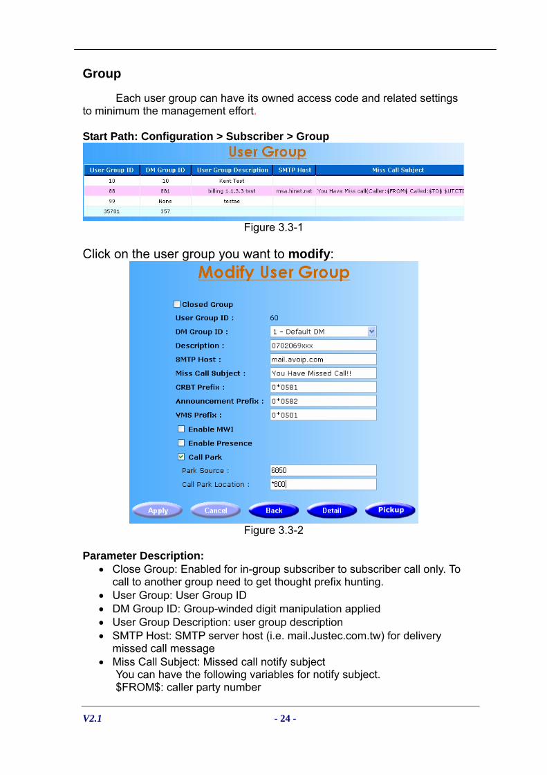
Group
Each user group can have its owned access code and related settings to minimum the management effort.
Start Path: Configuration > Subscriber > Group
Figure 3.3-1
Click on the user group you want to modify:
Figure 3.3-2
Parameter Description:
• Close Group: Enabled for in-group subscriber to subscriber call only. To call to another group need to get thought prefix hunting.
• User Group: User Group ID • DM Group ID: Group-winded digit manipulation applied • User Group Description: user group description • SMTP Host: SMTP server host (i.e. mail.Justec.com.tw) for delivery
missed call message • Miss Call Subject: Missed call notify subject
You can have the following variables for notify subject. $FROM$: caller party number

V2.1 - 25 -
$TO$: Called party number $UTCTIME$: UTC Time $LTIME$: Local Time $DOMAIN$: SIP Domain $HOSTIP$: Host IP address For example: You have a missed call from $FROM$ at $LTIME$
• CRBT Prefix: Extra prefix to be added when Coloring Ring Back Tone service is enabled.
• Announcement Prefix: Extra prefix to be added when Announcement service is enabled.
• VMS Prefix: Extra prefix to be added when VMS service is enabled. • Enable MWI: Enable MWI Service or not. MWI server subscriber ID is
required. • Enable Presence: Enable Presence Service or not. Presence Server
subscriber ID is required. • Call Park: Enable Call Park or not
- Park Source: The announcement server to play the music after call part for first party.
- Call Park Location: The Call Park Location starting code (e.g. 800, and the system will automatically add to 809, 10 locations in all.) It cannot be conflict with subscriber or prefix.
Click on the Detail button: It is Service code definition for the selected user group.
Figure 3.3-3
Parameter Description: • Service Code: Telephony Keypad used for the service code • Service Type: Applied service type

V2.1 - 26 -
The others please refer to the examples below: Forward Service:
Service Access Code
Parameter (optional) Example
*2010933111666 Enable unconditional forward *201 Forward number
*201 (use existing setting) *2020282265699 Enable no answer forward *202 Forward number *202 (use existing setting) *2030936111222 Enable busy forward *203 Forward number *203(use existing setting)
*204302 Enable unavailable forward *204 Forward number *204(use existing setting) Don’t disturb time 1
(hhmmhhmm) *20518002359
Don’t disturb time 1 & 2
(hhmmhhmmhhmmhhmm)
*2051800235901000900 Enable don’t disturb *205
*205(use existing setting) Enable Notify *206 n/a *206 (need pre-config by web) Enable Fine Me *207 n/a *207 (need pre-config by web) Enable CRBT *208 n/a *208 (need pre-config by web) Enable Announcement *209 n/a *209 (need pre-config by web) Enable VMS *210 n/a *210 (need pre-config by web) Disable unconditional forward *301 n/a *301 Disable no answer forward *302 n/a *302 Disable busy forward *303 n/a *303 Disable unavailable forward *304 n/a *304 Disable don’t disturb *305 n/a *305 Disable Notify *306 n/a *306 Disable Fine Me *307 n/a *307 Disable CRBT *308 n/a *308 Disable Announcement *309 n/a *309 Disable VMS *310 n/a *310
Hide ANI Service:
Service Access Code Parameter Example
Hide ANI *314 Dialed number *5070100001 (Hide caller ID)
Show ANI *214 Dialed number *607010062 (Show caller ID)
Pickup Call Service:
Service Access Code Parameter Call Pickup
Global Pickup *0 n/a *0 (global pickup) Group Pickup *1 n/a *1 (group pickup)
VAD Service:
Service Access Code Parameter Call Pickup
Camp On *211 070700001 *211070700001 Cancel Camp On *311 n/a *311 (cancel camp on) Call Return *212 n/a *212

V2.1 - 27 -
(No answer call return)
Call Pickup *213 301 *213301(assigned call pickup)
Call Park *215
Enable Privilege Access *216 070700001 (user’s password)
*216 (enable privilege access)
Disable Privilege Access *316 n/a *316 (disable privilege access)
Disable Call Waiting *217 n/a *217 Enable Call Waiting *317 n/a *317
Click on the Pickup button:
Grouping the subscribers for group pickup service, you can set a subscriber to belong to a pickup group.
Figure 3.3-4
Parameter Description: • Pickup Group ID: Pickup group ID • Description: Description
V2.1 - 28 -
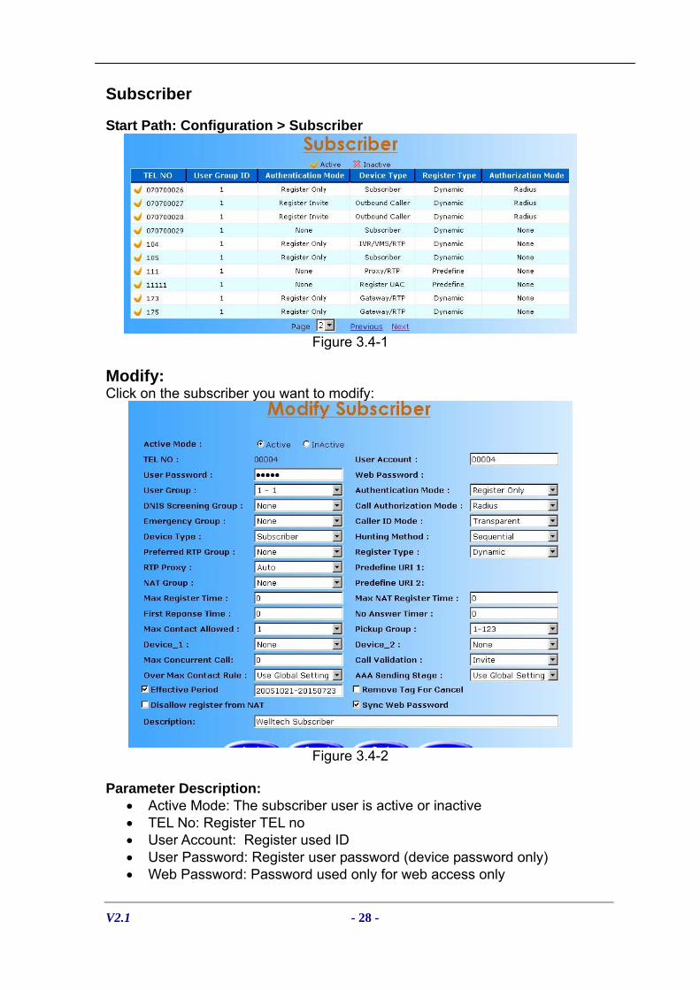
Subscriber
Start Path: Configuration > Subscriber
Figure 3.4-1
Modify: Click on the subscriber you want to modify:
Figure 3.4-2
Parameter Description:
• Active Mode: The subscriber user is active or inactive • TEL No: Register TEL no • User Account: Register used ID • User Password: Register user password (device password only) • Web Password: Password used only for web access only

V2.1 - 29 -
• User Group: Belonged User group • Authentication Mode: Authenticate subscriber by MD or not
- None: No - None: None - Radius: Send to RADIUS for call permission - Register Only: Authenticate subscriber only for register - Register Invite: Authenticate subscriber for register and each call
• DNIS Screening Group: DNIS screening group • Call Authorization Mode: Send authorization to Radius server or not • Emergency Group: Emergency call group • Call ID Mode: Displace caller ID or not
- Inhibit: Hide the called party number - Transparent: Pass through the caller ID
• Device Type: Subscriber device type - Subscriber: Subscriber user - Gateway: Gateway (e.g. trunk gateway or FXO gateway) - Gateway/RTP - Proxy/RTP - SIP Proxy: SIP proxy server - IVR/VMS: IP IVR or VMS server - IVR/VMS/RTP: IVR or VMS server - Recorder - Outbound Caller: Outbound Caller (SIPIVR 6800 is required) - Register UAC: Register user agent client
User Agent ID: User agnet ID in UAC Caller Info: Display calling parting information ▪ Caller TEL No: Display original caller ID ▪ Registered TEL No: Registered UAC user ID ▪ Caller Display Name: SIP display name for original caller
- LCS Server: Microsoft Live Communication Server - MWI Server: MWI Server - Presence Server: Presence Server - RTP Server: RTP Server - VMS (Diversion): The voice mail server which support diversion
header as draft-levy-sip-diversion-08.txt. - Web Caller: Allow unregistered subscriber to make call. Web Caller
license is required. Welltech will provide OCX and sample code for integrating into the customer’s Web server.
- Exchange Fax: Allow to provide the fax feature for Exchange 2007. Regular T.38 device can work with Exchange 2007 UMS when using this exchange fax user.
- Hunting Method: Call forking method. - Sequential: Call hunting each contact in sequence - Parallel (ringing): Send multiple call invites to multiple contacts
simultaneously. When receive the first 180 (ringing), use it and disconnect the others.
- -

V2.1 - 30 -
- Parallel (answer): Send multiple call invites to multiple contacts simultaneously. When a user pickup the phone, disconnect others contacts.
• Preferred RTP Host: Preferred RTP resource server to be used. • Register Type: Subscriber register type
- Dynamic: Subscriber need send register message for availability - Predefine: Subscriber will be handle as a permanent user
Predefine URI1: Predefine subscriber URI1 (i.e. sip:[email protected]) Predefine URI2: Predefine subscriber URI2 (i.e. sip:[email protected])
- Predefine/NAT: Subscriber will be handled as a permanent NAT user (manual IP/Port mapping is required)
Predefine URI 1: Predefine NAT subscriber URI (i.e. sip:[email protected]: 7777) Public TA: mapped NAT Server IP address and port (i.e. 61.218.42.217:5060)
• RTP Proxy: Use RTP Proxy or not - Yes: Always use the RTP Proxying - No: Always not use RTP Proxying - Auto: Automatic decide to use RTP Proxying or not (recommended) - Recorder: Use Recorder - Recording on Demand: Use Recorder on demand service - NAT Group: NAT group can be used for enterprise user. When two
subscribers have same NAT group defined, The Telephony SIP Proxy Server will not use NAT Proxying when both subscriber have same NAT group.
• Max Register Time: The maximum register time when a user is coming from public network
• Max Register NAT Time: Time: The maximum register time when a user is sited behind NAT
• Fast Response Time: The maximum time to wait for response. It’s depended on the network speed.
• No Answer Timer: The maximum time (in second) to wait the remote party answer (pick up phone).
• Max Contact Allowed: The maximum contact allowed for a subscriber. The new contact will not able to register when old one doesn't free up.
• Pickup Group: Pickup group for subscriber • Device_1, 2: Allowed device to be connected to The Telephony SIP
Proxy Server. • Max Concurrent Call: The maximum of concurrent call • Call Validation: The call validation type: none, update or invite
o None: disable call validation features o Update: Use SIP UPDATE instead of INVITE o Invite: Use SIP INVITE message for call validation
• Over Max Contact Rule: Over Max Contact Rule: reject, update or use Global Setting (Configuration > System)

V2.1 - 31 -
o Reject: The system will reject the new contact REGISTER
request when the subscriber’s used contacts reached the max contact
o Update: The system will replace the oldest contact by new received contact.
o Global Setting: Use system defined policy. • AAA Sending Stage: Send AAA message before or after DM. Or use
Global Setting (System > Advance) • Effective Period: The subscriber effective period (Format: yyyymmdd -
yyyymmdd) • Remove Tag for Cancel: When cancel the call, remove the “to tag” (for
CISCO device only) • Disallow Register From NAT: Enable this option will not allow a
subscriber to register behind NAT. In other words, this subscriber will never consume the RTP resource.
• Description: Description • Sync Web Password: Sync web password per subscriber
Service:
Click on the subscriber > service you want to modify telephony service for the selected user.

V2.1 - 32 -
Figure 3.4-3
Parameter Description: Forward Service:
• Unconditional: When enabled, any calls to this subscriber will be forward to this URI unconditionally. You can use SIP URI or subscriber ID here. - Disable Call Originate: When enable unconditional forward, the user
will not able to make call out if it is checked. • No Answer Forward: Forward to the URI when the subscriber has no
answer. • Busy Forward: Forward to the URI when the subscriber is busy. You can
use SIP URI or subscriber ID here. You can use SIP URI or subscriber ID here
• Unavailable Forward: Forward to the URI when the subscriber is unavailable (not registered). You can use SIP URI or subscriber ID here. You can use SIP URI or subscriber ID here
• 181 for Call Forward: Send SIP181 for Call Forwarded service • Announcement Before Forward: Play Announcement before call forward • Forward Subscriber Only: Forward to proxy subscriber only. • Find Me: Locate subscriber based on different time segment when the
original (registered) contact cannot be reached. - Find Me Hunting First: Hunting find me contact first. - Hunting Subscriber: Applicable only for Find me hunting checked will
hunt subscriber registered contact when find me can’t be reached. • Number Change: Change the original number to a new number.
Welltech IP Centrex 6850 is required for announcement service. • Auto Call Forward: Auto Call forward or not after number changed
Call Pickup: • Group Pickup (Picker): Allowed to be picked-up within group or not • Global Pickup (Picker): Allowed to be picked-up globally or not
Screening Service: • Personal ANI Screening: Personal ANI screening can be used to filter
the caller based on caller ID. For all TEL are set to allow (full match), only on-list ANI can get through. For all TEL are set to disallow, only on-list ANI will be screened. Otherwise, “disallow” has higher priority than “allow”.

V2.1 - 33 -
• Personal DNIS Screening: Personal DNIS screening can be used to
limit the called prefix. For all TEL are set to allow (prefix match), only on-list DNIS can get through. For all TEL are set to disallow, only on-list DNIS will be screened. Otherwise, “disallow” has higher priority than “allow”
• Do not disturb: Up-to 2 time segments can be set to reject all incoming calls.
VAD Service
• Coloring Ring Back: Coloring Ring Back Tone service • Announcement Service: Announcement Service • VMS: Voice Mail Service
Subscriber Service • Short Code: short code to be used within same group • ANI Replacement: Replace calling number for Gateway or all
subscriber • Replace ANI: Replace calling number • Replace Type: Gateway only or all subscribers • PSTN Number: This number will be handled as a PSTN number. It will
work like you have a second number in 6500. 6500 will look at the PSTN number first.
• Disable call forward display name: Add display name as subscriber id in SIP from header when call forward caller mode is "forwarder".
• Display Name: Assigned the display caller name for the subscriber. It will be showed on SIP IP phone.
• Missed Call URI: Missed call notify service • Disable Conference Call: Disallow to call a conference call • Support Video: Enable Support Video or not • Disable Call Waiting: Disable call waiting feature. When disable call
waiting features, the second incoming call to the user will be rejected by the SIP Telephony Server.
• Server Transfer: The server will do the transfer instead of send to CPE. It is recommended to use it only when CPE doesn’t support call transfer features. It is only happened when the user is transferred party.
Security
• Disable Un-Register All: Disable Un-Register all (use * to un-register all contacts)
• Disable RADIUS Billing Send: Disable RADIUS Billing Send
Misc. • Sync to Address: Make SIP TO head to be same as Request URI • Response to Sending Port: Response to CPE sending port instead of
register port. • Response to top via: Response to Top Via instead of register port • CTI: Computer Telephony Integration (reserved item)

V2.1 - 34 -
• Disable Qop: Disable sending qop tag in SIP 401 and 407
authentication header. Parameter Button
• Copy: Copy service setting from a subscriber • Mask: Set the subscriber visual view of the service. If you uncheck the
mask of a service, the subscriber login will not able to see it.
UAC
The SIP Telephony Server can register to another proxy server as a standard SIP UAC (User Agent Client). You can have hieratical SIP proxy architecture by using UAC settings.
Modify: Click on the subscriber > UAC you want to modify:
Figure 3.5-1
Parameter Description:
• User Agent ID: Identifier used for subscriber setting (type UAC) • Register ID: SIP registrar user ID • Register Password: SIP registrar user password • Register Realm: SIP registrar realm (domain) • Register IP: SIP registrar IP address • Register Port: SIP registrar UDP port number • Register TTL: The registration maximum time to live setting when
registered to the SIP registrar • Outbound Proxy User ID: SIP outbound proxy server user ID • Outbound Proxy Password: SIP outbound proxy server user password • Outbound Proxy IP: SIP outbound proxy server IP address • Outbound Proxy Port: SIP outbound proxy server port number • Description: Description • Encrypt: The device for UAC is encrypted or not.

V2.1 - 35 -
To set a subscriber as a register client, choose register type to "register
UAC". Then you can use this subscriber Tel number for prefix hunting.
NAT
NAT group can be used for enterprise user. When two subscribers have same NAT group defined, The Telephony SIP Proxy Server will not use NAT Proxying when both subscriber have same NAT group. You have to define NAT group definition by detail, or same IP address detect policy will be used.
Start Path: Configuration > NAT
Figure 3.6-1
Modify: Click on the group ID > Modify you want to modify:
Figure 3.6-2
Basic Parameter Description: • IP Address: public IP address on NAT • Submask: network mask
For example: IP: 61.218.42.224 Submask: 255.255.255.248 NAT Group Definition: 61.218.42.224 to 61.218.42.238

V2.1 - 36 -
IP: 61.218.42.0 Submask: 255.255.255.0 NAT Group Definition: 61.218.42.0 to 61.218.42.225
RTP Resource
This feature can be used only for external RTP resource server. By using this feature, the SIP Telephony Server can have more concurrent RTP proxying channels. You can define different RTP group for different purposes (e.g. by different ISR providers).
Start Path: Configuration > RTP Resource
Figure 3.7-1
Basic Parameter Description: • Group ID: RTP Server Group ID • Description: Description
Click on the Detail button:
Figure 3.7-2
Parameter Description: • User ID: RTP Server User ID • Priority: The RTP Server priority

V2.1 - 37 -
After define the installed RTP resource server, you can set the
preferred RTP proxy server group, in subscriber menu, to be used. The SIP telephony Proxy Server will use RTP resource severs according to priority assigned within same group. Call Interception
Call Interception can provide interception service through target call number, be sure that you have an external Recorder Server installed
Start Path: Configuration > Call Interception
Figure 3.8-1
Basic Parameter Description: • Target Number: The call number to be intercepted • Description: Description
Prefix Route
The Telephony SIP Proxy Server Prefix Route can provide prefix hunting base on priority, max idle time or round robin method. The SIP telephony Proxy Server will use prefix routing plan to do the corresponding routing. The routing target can be a UAC (register client), another proxy, gateway or subscribers....etc. Routing policy is defined here.

V2.1 - 38 -
Start Path: Configuration > Prefix Route
Figure 3.9-1
Modify Prefix Route List: Click on the Modify button:
Figure 3.9-2
Parameter:
• Active Mode: The prefix group is active or inactive • Prefix Matched: Called number prefix to be matched • Description: Description • Matched Length: Applied only when specified length of DINS is
matched. Zero (0) indicate ignore length option. • Matched User Group: Applied only for specified user group. Others
group will not be applied. • Hunting Method: Hunting method used for this group
- Round Robin: Call is hunting rotationally until user answer - Priority: Call is hunting base on priority set until user answer - Max Idle Time: Max idle one will be hunt first until user answer - Ring All (First Ring): Send request to all members. When a user
response ringing, cancel the others request. - Ring All (First Answer): Send request to all members. When a user
pickup the phone, cancel the others request.

V2.1 - 39 -
- Round Robin (Ring Only): Send request based on round robin
member selection. Stop hunting when a user response ringing. - Priority (Ring Only): Send request based on member's priority. Stop
hunting when a user response ringing. - Max Idle Time (Ring Only): Send request base most idle policy. Stop
hunting when a user response ringing. - Round Robin (Load Balance): Send request based on round robin
member selection. Stop hunting when a call is failed except receiving the defined reason code in load balance reason.
- Priority (Load Balance): Send request based on member's priority. Stop hunting when a call is failed except receiving the defined reason code in load balance reason.
- Max Idle Time (Load Balance): Send request base most idle policy. Stop hunting when a call is failed except receiving the defined reason code in load balance reason.
- No Answer Timeout: The maximum time (in second) to wait the remote party answer (pick up phone)
• First Response Timeout: The maximum time to wait for device response. It’s depended on the network speed.
• Remove Prefix: Remove prefix matched or not • RADIUS Authorization Resend: Send RADIUS authorization for each
prefix hunting. Click Detail to define member of prefix routing group. Click on the Detail button:
Figure 3.9-3
Parameter:
• TEL NO: Subscriber TEL no for route • Priority: Used only for priority hunting.

V2.1 - 40 -
Click on the L.B Reason button:
When enable load balance hunting, here is the cause reason to enable The Telephony SIP Proxy Server to continue the hunting.
Figure 3.9-4
Parameter: • State Code: SIP State code to continue the hunting
Digit Manipulation
The Telephony SIP Proxy Server Digit Manipulation can provide operator target called number and calling number to “insert, replace or drop”. Start Path: Configuration > Digit Manipulation
Figure 3.10-1

V2.1 - 41 -
Click on the Detail button:
Figure 3.10-2
Modify Digit Manipulation:
System is able to execute 1 ANI DM and 1 DNIS DM separately for calling and called party. The default will be the caller which is same as the old version. Matched ANI DM will be executed first and use the result for DNIS DM.
Click on the Modify button:
Figure 3.10-3
Parameter: • Matched Prefix: Calling/Called number party matched • Matched Target: Matched target is ANI(calling number) or DNIS(called
number) • OP Target: Operator target is ANI(calling number) or DNIS(called number) • Matched Length: matched length of the target number • Apply Target: The target which the operation is executed.

V2.1 - 42 -
o Caller: When the subscriber is making a call, the DM will be
applied o Called: When the subscriber is received a call, the DM will be
applied. o Both: When the subscriber is making a call or receive a call, the
DM will be applied. • Active Mode: The DM group is active or inactive • Start Position: Start position to be replaced • Stop Position: Stop position to be replaced • Replace Value: Replaced value
Example:
Group ID 88 35701 99 811360601 Subscriber ID 070700023 070700024
070100007
Digit Manipulation Setting DM Group ID 881 314 991 Matched Prefix 8226 070 070 Matched Target DNIS ANI DNIS OP Target DNIS ANI ANI Matched Length 8 0 0 DM Apply Target Caller Both Called Start Position 0 0 0 Stop Position 0 3 1 Replace Value 886 557 991 Call Test Example:
Call Test Number Display
070700023 > 82265555 DNIS: 88682265555 ANI: 070700023
070700023 > 070100007 DNIS: 070100007 ANI: 99170700023
070700023 > 811360601 DNIS: 811360601 ANI: 557700023
811360601 > 070100007 DNIS: 070700023 ANI: 99111360601
811360601 > 82265555 DNIS: 070700023 ANI: 811360601
811360601 > 070700023 DNIS: 070700023 ANI: 811360601
070100007 > 070700023 DNIS: 070700023 ANI: 070100007
070100007 > 811360601 DNIS: 811360601 ANI: 557100007
070700024 > 070100007 DNIS: 070100007 ANI: 557700024
070700024 > 070700023 DNIS: 070700023 ANI: 557700024

V2.1 - 43 -
DNIS Screening
DNIS screen group can be used to limit the called prefix. Start Path: Configuration > DNIS Screening
Figure 3.11-1
Click on the Detail button:
Figure 3.11-2
Parameter: • Screening Prefix: Called number prefix • Screening Type: Allow or disallow
When all TEL are set to allow (prefix match), only on-list DNIS can get
through. When all TEL are set to disallow, only on-list DNIS will be screened. Otherwise, “disallow” has higher priority than “allow”

V2.1 - 44 -
Emergency Call
To have subscriber-based emergency call setting, please define the required emergency call here and select it on subscriber basis.
Start Path: Configuration > Emergency Call
Figure 3.12-1
Click on the Detail button:
Figure 3.12-2
Parameter: • Emergency Number: Emergency called number (e.g. 911) • Routed Number: Actually called number to be dial out (e.g. 0222211111)

V2.1 - 45 -
AAA
When the subscriber users do the AAA (Authorization, Authentication and Accounting), enter the correct parameter the Radius setting.
Start Path: Configuration > AAA
Figure 3.13-1
Parameters:
• Auth IP: Radius Authentication Server IP address • Auth Port: Radius Authentication Server Port • Acct IP: Radius Account Server IP address • Acct Port: Radius Account Server Port • Backup Auth IP: Backup Radius Authentication Server IP address • Backup Auth Port: Back Radius Authentication Server Port • Backup Acct IP: Back Radius Account Server IP address • Backup Acct Port: Back Radius Account Server Port • Secret Key: The shared secret key with RADIUS Server • Max Retry: The maximum retry times • Response Time (sec): The maximum wait for response time from
RADIUS Server • Auth Retry Interval (sec): The internal to resend the Authentication
packet to RADIUS Server. • Acc Retry Interval (sec): The internal to resend the Account packet to
RADIUS Server. • Switch Threshold: Switch to alternate RADIUS Server when failures are
occurred more than switch threshold. • CDR Mode:
- Enable: Log CDR into the file - Disable: no
• CDR Keeper Days: CDR system keeping days • Vendor ID: RADIUS vender attribute’s vender ID.(Default is 9) • Cisco Mode:
- Yes: Use Cisco RADIUS mode (have redundant string in vender attribute)
- No: no

V2.1 - 46 -
• Send Nero Session Time:
- Yes: Send 0-balance session time for RADIUS when the call failed - No: no
• Inter-Subscriber RADIUS Authentication: - Yes: When a subscriber is calling another subscriber, The Telephony
SIP Proxy Server will send RADIUS for call permission - No: When a subscriber calling another subscriber, The Telephony SIP
Proxy Server will not send RADIUS for call permission • Inter-Subscriber RADIUS Billing:
- Yes: Send RADIUS billing message for Inter-Subscriber calls - No: Do not send RADIUS billing message for Inter-Subscriber calls
• Billing Message: Send RADIUS billing message out
Configuration Manager Configuration Management provides a way to save and backup and restore the working configuration here. Backup the working configurations: Step 1: To backup the running configuration, click on Backup Configuration,
to back up local hard disk as figure 3.11-1.
Figure 3.14-1
Step 2: The whole running configuration will be compress into a zip file (file
name: export.zip) and transfer back to local as figure 3.11-2.
Figure 3.14-2
Restore Configuration: Step 3: To restore the backup configuration file, click Restore Configuration
as figure 3.11-3.
Figure 3.14-3

V2.1 - 47 -
Step 4: Select backup file (i.e. c:\export.zip) click on Import button to restore
the configuration to the working configuration as figure 3.11-4.
Figure 3.14-4
☺Note: It is need to restart the system to take effect of the new-restored
working configuration.
Compact the database file: Step 5: In order to optimize the system performance, you can optional
compact the database by click Compact button as figure 3.11-5.
Figure 3.14-5
☺ Note: Please make sure that there is no others person to use database concurrently.

V2.1 - 48 -
Chapter 4 System Control Reference
System
Start path: Click Control > System
Figure 4.1-1
Parameter:
• Soft Reset: Soft Reset at the Telephony SIP Proxy Server • Upgrade Reset: Soft reset after application upgrade. The new
application image will be extracted and executed without reboot. • Restart: Restart the the Telephony SIP Proxy Server • Shutdown: Shutdown the the Telephony SIP Proxy Server
System Time
Time Zone Setting Step 1: If you would like to use time zone, click Time Zone button to setup
the system time zone as figure 4.2-1.
Figure 4.2-1
Standard: Step 2: Select the Standard option to setup the system predefined time zone
as figure 4.2-2
Figure 4.2-2

V2.1 - 49 -
Parameter:
• Time Zone: o Standard: Use a predefined standard time zone (Refer to section
“Timezone to Country Mapping List” ) o Customize: Use a user defined time zone
• Auto Daylight Saving: Auto adjust daylight saving time or not User defined Time Zone: Step 3: Select the Customized option and enter the time zone bias to set a
user defined time zone as figure 4.2-3
Figure 4.2-3
Parameter:
• Daylight Bias: The offset added to the Bias when the time zone is in daylight saving time
• Daylight Start: The date that a time zone enters daylight time o Month: 01 to 12 o Week Day: Sunday to Saturday o Apply Week (Day:01 to 05, Specifies the occurrence of day in the
month; 01 = First occurrence of day, 02 = Second occurrence of day, ...and 05 = Last occurrence of day)
o Hour: 00 to 23 • Standard Start: The date that a time zone enters daylight time
o Month: 01 to 12 o Week Day: Sunday to Saturday o Apply Week (Day:01 to 05, Specifies the occurrence of day in the
month; 01 = First occurrence of day, 02 = Second occurrence of day, ...and 05 = Last occurrence of day)
o Hour: 00 to 23

V2.1 - 50 -
Network
Management interface it’s used for management purpose. If you have DNS record, also you must be setup DNS server to effect. ☺Note: SIP Service and Manager Interface Setting: Please refer to section “Network Configuration” DNS Server Setting: Step 1: Enter correct DNS server IP address, host name, domain name and
dynamic DNS registration to “Yes”. Apply change by click Apply button as figure 4.3-1.
Figure 4.3-1
Parameter:
• Primary DNS Server: Primary DNS Server IP network • Secondary DNS Server: Secondary DNS Server IP network • Host Name: Host name used to register to DNS Server • Domain Name: Domain name used to • Dynamic DNS Registration: Enable Dynamic DNS registration or not
Voice Gateway Setting:
Voice gateway mode needs 2 network legs. SIP service Ethernet leg need to be on WAN side and management interface Ethernet leg will be used for private IP leg. This feature private IP leg. This feature provides NAT server and voice only firewall functions. Step 1: Select Configuration > System > Advance > Voice Gateway to “Yes”.
Apply change by click Apply button as figure 4.3-2.

V2.1 - 51 -
Figure 4.3-2
Step 2: Select Control > Network > LAN, click Route button as figure 4.3-2.
Figure 4.3-3
New the routing table:
Figure 4.3-4
In Private IP Ethernet leg, The Telephony SIP Proxy Server can also provides routing command for LAN to route their IP traffics. It is useful for those companies had different LAN or VPN network.
Parameter:
• Destination: Target IP address or network • Netmask: Network mask • Gateway: Destination gateway • Metric: Routing priority
V2.1 - 52 -
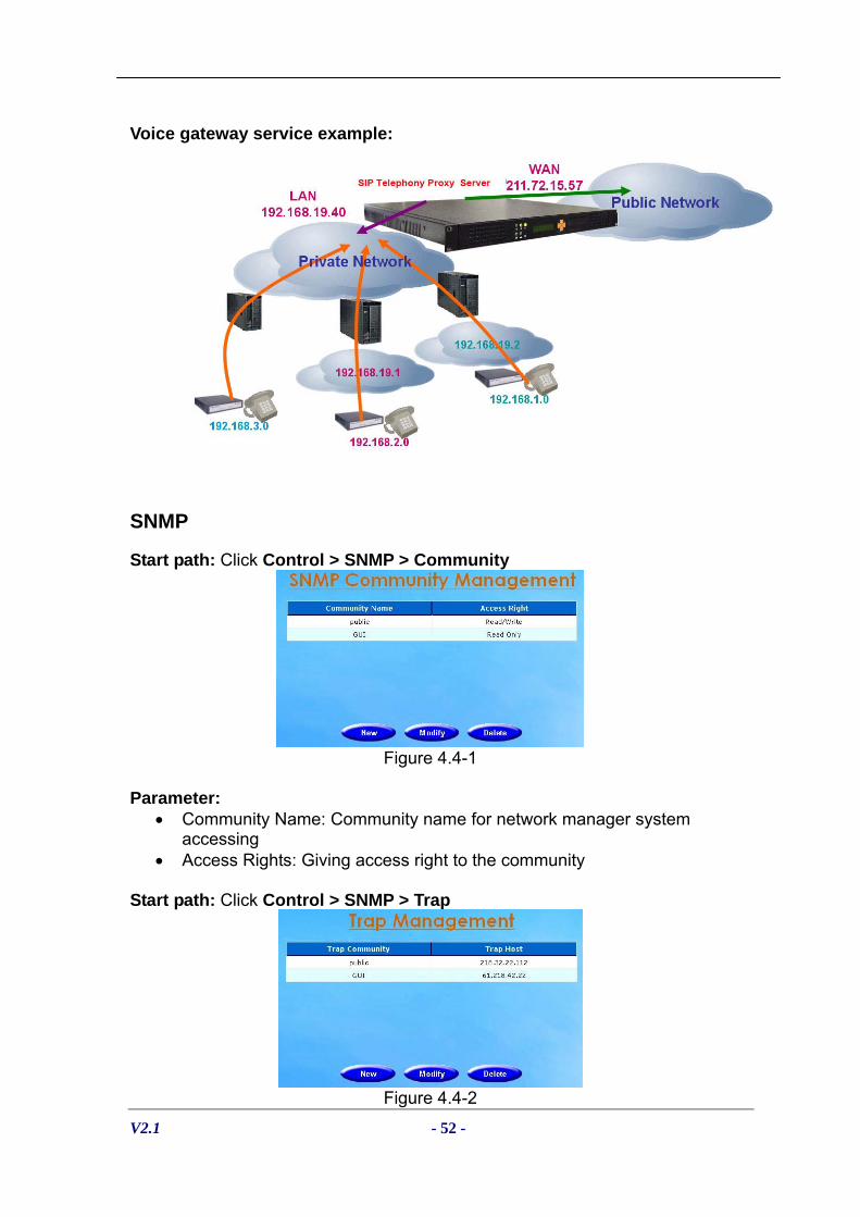
Voice gateway service example:
SNMP
Start path: Click Control > SNMP > Community
Figure 4.4-1
Parameter:
• Community Name: Community name for network manager system accessing
• Access Rights: Giving access right to the community Start path: Click Control > SNMP > Trap
Figure 4.4-2

V2.1 - 53 -
Parameter: • Trap Community: Trap community name for NMS • Trap Host: Trap host IP address
☺Note: It takes around 1-minute to update SNMP configuration and
display successful message.
Account Manager
You can manage (Modify, Add and Delete) the login user account as follows:
Step 1: Click Control > Account Manager as figure 4.5-1
Figure 4.5-1
Field Description:
• User ID: Login User ID • Password: Login Password • Confirm Password: Confirm new password again • Ownership: The ownership of the web management
- Admin: super user - Monitor: view only
☺Note: The system provides 2 USER ID by default:
User 1: “root” Password: “root” User 2: “admin” Password: “admin”
Provisional IP
The Telephony SIP Proxy Server can be integrated with other system, such billing system, web server etc, by using provisional interface. To implement the provisional interface, high security communication protect is required. However, to minimize the developing effort, the trusted provisional host can be defined in here. For those host/IP defined here, it will communicate without any security protect for provisional.

V2.1 - 54 -
Step 1: Click “Control > Provisional IP” to upgrade the software as figure 4.6-1.
Figure 4.6-1
Field Description:
• Trust IP: Trust provisional host IP • Enable:
-Yes: enabled - No: disabled
Upgrade
The Telephony SIP Proxy Server provide upgrade new version at remote side. You can upgrade it from Welltech technical support web page by yourself. Step 1: Click “Control > Upgrade” to upgrade the software as figure 4.7-1.
Figure 4.7-1
Field Description:
• File Name: Upload the software file name • Upload: Remote Upload the software at The Telephony SIP Proxy
Server
Relogin
Step 1: Click Control > Relogin to relogon by another user account as figure 4.8-1.

V2.1 - 55 -
Figure 4.8-1

V2.1 - 56 -
Chapter 5 System Monitor Reference
It provides a way to monitor the system status.
Subscriber Status
Show subscriber users status.
Start Path: Monitor > Subscriber Status > Monitor button key-in the TEL No. and click Apply button to be controlled.
Figure 5.1-1
Figure 5.1-2

V2.1 - 57 -
See the Subscriber Detail:
Select a subscriber and double-click to “Subscriber Detail” as figure 5.1-2.
Figure 5.1-3
Field Description:
• TEL NO: registered TEL number • Register: Registered or not • Call Count: number of concurrent calls for the user • Call Status: Detail is showed for subscriber. Summary only is used for
gateway user. • Contact: Registered contact URI • NAT: NAT IP address • Register Time: Register time • TTL: Register time to live • Registrar: Registered Proxy IP and port • Unreg: Un-register the subscriber • Disconn: Disconnect the connected call

V2.1 - 58 -
Call Statistics
Show total call statistics records . Start Path: Monitor > Call Statistics
Figure 5.2-1
Field Description:
• Time: statistic period in 24 hours format • Call: For the current period, this field showed real time concurrent call.
For the past period, this field showed the concurrent call for last seconds. For example, if current time is 10:30, the 10-11 time period show the real time concurrent call and the 9-10 time period show the concurrent call right on 10:00.
• Peak Call: In this period, the max call reached. • Total Call: The total call processed in the period • Connected Call: For the current period, this field showed real time
connected call. For the past period, this field showed the connected call for last seconds. For example, if current time is 10:30, the 10-11 time period show the real time connected call and the 9-10 time period show the connected call right on 10:00.
• Peak Connected Call: The max connected call in the period • Total connect call: The total connected call in this period • Register: For the current period, this field showed real time registered
count. For the past period, this field showed the register count for last seconds. For example, if current time is 10:30, the 10-11 time period show the real time registered call and the 9-10 time period show registered count right on 10:00.
• Peak Register: The max registered count

V2.1 - 59 -
RTP Status
Show RTP resource server status. At least the sip telephony proxy server itself will be showed here as an internal RTP resource server when have no extra RTP resource server is defined. Start Path: Monitor > RTP Status
Figure 5.3-1
RTP Statistics
Show RTP count statistics Start Path: Monitor > RTP Statistics
Figure 5.4-1
Field Description:
• Time: statistic period in 24 hours format • Max NAT: The NAT resource capacity • NAT Call: For the current period, this field showed real time NAT
resource is used. For the past period, this field showed the NAT count for last seconds. For example, if current time is 10:30, the 10-11 time period show the real time NAT call in this server and the 9-10 time period show NAT calls right on 10:00.

V2.1 - 60 -
• NAT Peak Call: The max NAT call in this period • NAT Total Call: Total NAT calls in this period • NAT Fail Call: NAT failed call in this period. It might be indicating the
resource is exhausted.
Server Status
Show current server status Start Path: Monitor > Server Status
Figure 5.5-1
Field Description:
• Application : System application • Version: Application version • Status: Server status • Call Attempt: The number of concurrent call attempts • NAT Call: The number of concurrent NAT Calls • Register: The number concurrent Register clients • Max Call: Max current call • Current Call: Used call • Max Transaction: Max transaction • Used Transaction: Used transaction • Memory Pool: Max memory pool • Used Memory: Used memory pool

V2.1 - 61 -
Event Log
Show system event log status. Start Path: Configuration > Event Log
Figure 5.6-1
Field Description:
• Type: Event Log type - Information - Warring - Error
• Date: Event created date • Time: Event created time • Source: Executable program • Category: Event type (none, Welltech Sys…) • Event ID: Event Log
☺ Note: You can click Clear button to clear all event log. See the detail event log: Click the event log or select the log and click detail to see the log detail.
Figure 5.6-2

V2.1 - 62 -
Event Description:
Event ID Event Description Description 8000 Get initial data fail Failed to start application
8001 Create DB Connection fail Failed to start application
8002 Create thread fail Failed to start application
8003 Unable to start socket Failed to start application
8004 Initial SIP callback function fail Failed to start application
8700 Get new application transaction fail Failed to start application
8701 Over subscriber license limit Over subscriber license limit AP Logger SIPPD program started Miss Call Notify Miss Call Notify Started 9500 Telnet Svr Telnet Svr Started
9501 AP Logger On the fly change (system change)
9510 AP Logger NAT Proxy Started
9530 AP Logger AAA Mgr start
9540 AP Logger Status Teller Started
9550 AP Logger Provisional Gateway Started
9600 SNTP client application started SNTP is started
☺ Note: You should see the Event ID 9500~ 9600 in normal time.
Debug Info
Shows detail trace level messages.
Start Path: Click “Monitor > Debug Info”
Figure 5.7-1
Filed Description:
• Get Log: Get debug logs (-1~999) • Clear: Clear logs

V2.1 - 63 -
Ping
You can use the “Ping” to check an IP is active or not. Start Path: Configuration > Ping
Figure 5.8-1
Field Description:
• Host IP Address: The IP address to ping

V2.1 - 64 -
Chapter 6 Telnet & RS-232 Configuration
The Telephony SIP Proxy Server also can support to be managed by Telnet or Console port (RS-232) for basic operations.
Interface:
Network: TCP/IP Telnet (i.e. telnet 192.168.67.1 10086) RS232:
- Connect using: COM1 - Baud Rate: 9600 - Data bits: 8 - Parity: None - Stop bits: 1 - Flow Control: None - Wire: Null modem line (crossed)
Logon The Telephony SIP Proxy Server by Telnet
Use Windows build-in Hyper Terminal or other telnet terminal emulator to login (e.g. telnet 192.168.67.1:10086). User ID & password will be required for login (default login user id: admin, password: admin & user id: root, password: root). Command List:
Command Description echo Auto echo on or off Event log Clean or show system log message exit Quit the current session IP config Configure or show network1,2 information ping Check an IP address is available or not reboot Reboot reset Soft-reset shutdown Shutdown time Reset or show system time. Time zone Setup or show system time zone User admin Manage user account. help & ? View command list Echo: auto echo on or not
Command Purpose [root#]echo ? Usage: echo on/off
Example: echo on [root#]echo on Echo is on [root#]echo off Echo is off (default value)

V2.1 - 65 -
Event log: show system log message
Command Purpose [root#]event log ? Usage: event log [-clear]
Example: event log Event log -clear
[root#]event log Show system event log: Event log example: [root#] event log Time: 2005-04-11 14:07:34 Event ID: 9501 Type: Information Source : SIPPD Description: [14:07:34-461][Information]: SIPPD on the fly change Time: 2005-04-11 14:01:12 Event ID: 9500 Type: Information Source : SIPPD Description: [14:01:12-141][Notice]: SIPPD Started(ver 2.02) Time: 2005-04-11 13:57:32 Event ID: 9500 Type: Information Source : SIPPD Description: [13:57:32-054][Notice]: SIPPD Started(ver 2.02) Press any key to continue or press 'Q' to quit Press any key to continue or press 'Q' to quit
[root#]event log -clear
Clear all event log
Exit: Quit the current session
Command Purpose [root#]exit Quit the current session
ipconfig: Configuration or show network information
Command Purpose [root#] ipconfig ? Usage: ip config [-network boardno][-delete dns] [-dhcp] [-
dns IPAddress1 IP Address2 ] [-ip IP Address -mask Mask -gateway Gateway] Example: ipconfig -network 1 -ip 192.168.67. 1 -mask 255.255.0.0 -gateway 1 92.168.5.254 example : ipconfig -network 1 -dhcp example : ipconfig -network 1 -dns 192.168.1.1 example : ipconfig -network 1 -delete dns
[root#]ipconfig Show current network configuration [Network 1] Local Area Connection USE FIXED IP (or DHCP) IP Address : 192.168.5.7 Subnet Mask : 255.255.0.0 Default Gateway : 192.168.5.254 DNS Servers : [Network 2] Local Area Connection 2 USE FIXED IP IP Address : 192.168.5.8 Subnet Mask : 255.255.0.0 Default Gateway : DNS Servers :
V2.1 - 66 -
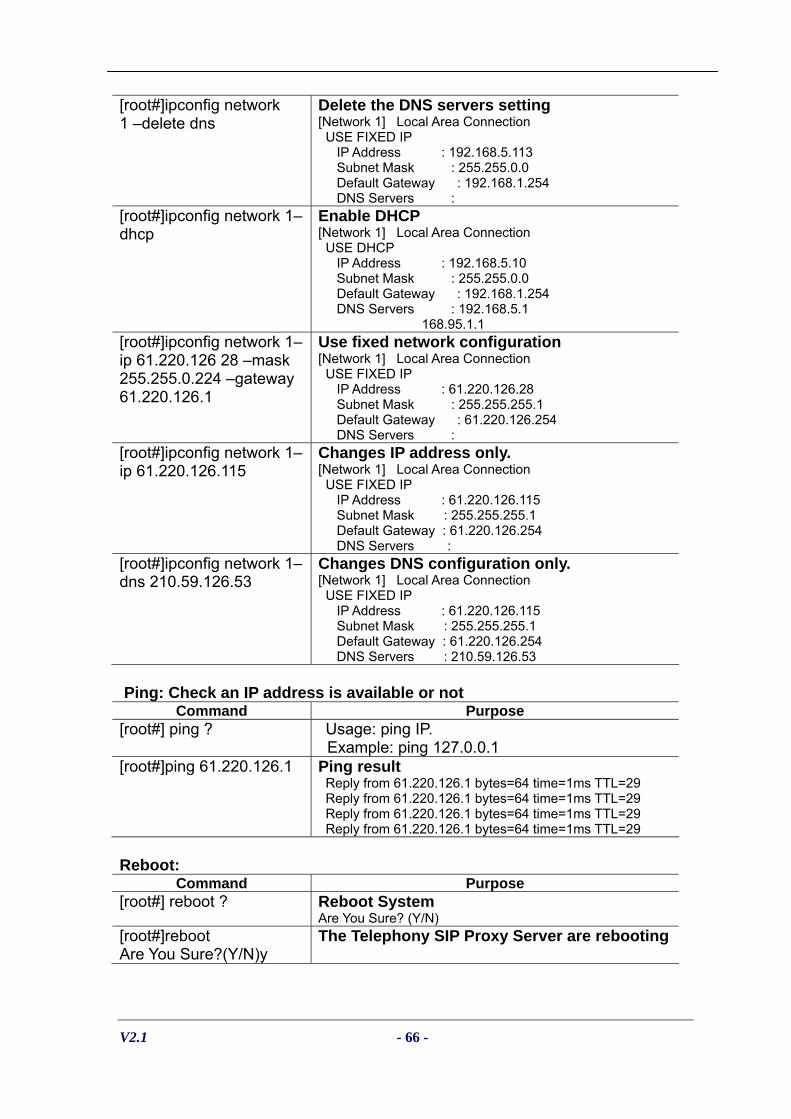
[root#]ipconfig network 1 –delete dns
Delete the DNS servers setting [Network 1] Local Area Connection USE FIXED IP IP Address : 192.168.5.113 Subnet Mask : 255.255.0.0 Default Gateway : 192.168.1.254 DNS Servers :
[root#]ipconfig network 1–dhcp
Enable DHCP [Network 1] Local Area Connection USE DHCP IP Address : 192.168.5.10 Subnet Mask : 255.255.0.0 Default Gateway : 192.168.1.254 DNS Servers : 192.168.5.1 168.95.1.1
[root#]ipconfig network 1–ip 61.220.126 28 –mask 255.255.0.224 –gateway 61.220.126.1
Use fixed network configuration [Network 1] Local Area Connection USE FIXED IP IP Address : 61.220.126.28 Subnet Mask : 255.255.255.1 Default Gateway : 61.220.126.254 DNS Servers :
[root#]ipconfig network 1–ip 61.220.126.115
Changes IP address only. [Network 1] Local Area Connection USE FIXED IP IP Address : 61.220.126.115 Subnet Mask : 255.255.255.1 Default Gateway : 61.220.126.254 DNS Servers :
[root#]ipconfig network 1–dns 210.59.126.53
Changes DNS configuration only. [Network 1] Local Area Connection USE FIXED IP IP Address : 61.220.126.115 Subnet Mask : 255.255.255.1 Default Gateway : 61.220.126.254 DNS Servers : 210.59.126.53
Ping: Check an IP address is available or not
Command Purpose [root#] ping ? Usage: ping IP.
Example: ping 127.0.0.1 [root#]ping 61.220.126.1 Ping result
Reply from 61.220.126.1 bytes=64 time=1ms TTL=29 Reply from 61.220.126.1 bytes=64 time=1ms TTL=29 Reply from 61.220.126.1 bytes=64 time=1ms TTL=29 Reply from 61.220.126.1 bytes=64 time=1ms TTL=29
Reboot:
Command Purpose [root#] reboot ? Reboot System
Are You Sure? (Y/N) [root#]reboot Are You Sure?(Y/N)y
The Telephony SIP Proxy Server are rebooting

V2.1 - 67 -
Shutdown:
Command Purpose [root#] shutdown ? Shutdown System
Are You Sure? (Y/N) [root#]shutdown Are You Sure?(Y/N)y
The Telephony SIP Proxy Server are shutting down
Reset:
Command Purpose [root#] reset ? Soft reset System
Are You Sure? (Y/N) [root#]reset Are You Sure?(Y/N)y
Time: Reset or show system time
Command Purpose [root#] time ? Usage : time YYYY-MM-DD HH:NN:SS
Example : Time 2002-01-01 12:00:00 [root#]time
Show current time The current time is 2003-06-20 15:17:30
[root#]time 2003-07-29 23:14:53
Change system bios time
Time Zone: Setup or show system time zone
Command Purpose

V2.1 - 68 -
[root#] timezone ? Fixed Zone List: 01. Afghanistan Standard Time 03. Arab Standard Time 05. Arabic Standard Time 07. AUS Central Standard Time 09. Azores Standard Time 11. Cape Verde Standard Time 13. Cen. Australia Standard Time 15. Central Asia Standard Time 17. Central European Standard Time 19. Central Standard Time 21. Dateline Standard Time 23. E. Australia Standard Time 25. E. South America Standard Time 27. Egypt Standard Time 29. Fiji Standard Time 31. GMT Standard Time 33. Greenwich Standard Time 35. Hawaiian Standard Time 37. Iran Standard Time 39. Korea Standard Time 41. Mexico Standard Time 2 43. Mountain Standard Time 45. N. Central Asia Standard Time 47. New Zealand Standard Time 49. North Asia East Standard Time 51. Pacific SA Standard Time 53. Romance Standard Time 55. SA Eastern Standard Time 57. SA Western Standard Time 59. SE Asia Standard Time 61. South Africa Standard Time 63. Taipei Standard Time 65. Tokyo Standard Time 67. US Eastern Standard Time 69. Vladivostok Standard Time 71. W. Central Africa Standard Time 73. West Asia Standard Time 75. Yakutsk Standard Time
02. Alaskan Standard Time 04. Arabian Standard Time 06. Atlantic Standard Time 08. AUS Eastern Standard Time10. Canada Central Standard Time 12. Caucasus Standard Time 14. Central America Standard Time 16. Central Europe Standard Time 18. Central Pacific Standard Time 20. China Standard Time 22. E. Africa Standard Time 24. E. Europe Standard Time 26. Eastern Standard Time 28. Ekaterinburg Standard Time30. FLE Standard Time 32. Greenland Standard Time 34. GTB Standard Time 36. India Standard Time 38. Israel Standard Time 40. Mexico Standard Time 42. Mid-Atlantic Standard Time 44. Myanmar Standard Time 46. Nepal Standard Time 48. Newfoundland Standard Time 50. North Asia Standard Time 52. Pacific Standard Time 54. Russian Standard Time 56. SA Pacific Standard Time 58. Samoa Standard Time 60. Singapore Standard Time 62. Sri Lanka Standard Time 64. Tasmania Standard Time 66. Tonga Standard Time 68. US Mountain Standard Time70. W. Australia Standard Time 72. W. Europe Standard Time 74. West Pacific Standard Time

V2.1 - 69 -
Usage1 : timezone zone (1 to 75) Auto Daylight (Y or N) Example1 : time zone 1 Y Usage2 : time zone -custom Bias Daylight Bias Daylight Start Standard Start Bias : -12:00 to +13:00 Daylight Bias : -12:00 to +13:00 Daylight Start : MM (Month: 01 to 12) ; WD (Day of week: 00 to 06) DD (Day:01 to 05 ;Specifies the occurrence of day in the month; 01 = First occurrence of day, 02 = Second occurrence of day, ..., 05 = Last occurrence of day HH (Hour:00 to 23) Standard Start : MM (Month: 01 to 12) ; WD (Day of week: 00 to 06) DD (Day:01 to 05 ;Specifies the occurrence of day in the month; 01 = First occurrence of day, 02 = Second occurrence of day, ..., 05 = Last occurrence of day HH (Hour:00 to 23) Example2 : time zone -custom +08:00 -01:00 04-00-01-02 10-00-05-02
[root#]time zone
Show current time zone info Time Zone : (40) Mexico Standard Time (GMT -06:00) Daylight Bias : -01:00 Daylight Start : 05-00-01 02:00 Standard Start : 09-00-05 02:00 Auto Daylight : Y
[root#]time zone 40 n
Use pre-defined time zone Time Zone : (40) Mexico Standard Time (GMT -06:00) Daylight Bias : -01:00 Daylight Start : 05-00-01 02:00 Standard Start : 09-00-05 02:00 Auto Daylight : n
[root#]timezone -custom +08:00 -01:00 05-00-01-03 09-00-05-03
Use customized time zone Time Zone : (99) Customized (GMT 08:00) Daylight Bias : -01:00 Daylight Start : 05-00-01 03:00 Standard Start : 09-00-05 03:00 Auto Daylight : Y
Useradmin: Manager User account
Command Purpose [root#] useradmin ? Usage: useradmin [-add User] [-delete User] [-
password User] Example: useradmin -add irene
[root#]useradmin
Show the current login user account root
[root#]useradmin -list Show the current user account list admin root irene

V2.1 - 70 -
[root#] useradmin -add irene Password : irene Confirm : irene Add user Success.
Add the new user account: irene
[root#] useradmin -delete 1111 Are You Sure?(Y/N)y
Delete the user: 1111
[root#] useradmin -password root New Password : 1234 Confirm : 1234
Change the user: root’s password.

V2.1 - 71 -
Chapter 7 LCD Display Configuration
The Telephony SIP Proxy Server provides a front panel LCD for basic operations.
Button List:
Button List Description
When the The Telephony SIP Proxy Server is ready, the LCD screen shows as blow
Enter
Press Enter to select command
ESC Quit the current command ▲ Up or previous edit mode ▼ Next or previous edit mode Command Tree: Main Menu
Event Log Show system log message
Show IP Info
Use DHCP Use
IP Config
Network 1 Network 2
Fixed IP
Yes
Reboot
No
Yes
Reset PWD
No
Yes
Soft Reset
No
Shut Yes
Ready | 04-03-03 16:40
Event Log IP Config

V2.1 - 72 -
Down No Event Log:
Configure LCD Display ▲ Previous event log ▼ Next event log Enter Show detail event log ▲ Previous line ▼ Next line ESC Quit detail event log viewing ESC Quit to main menu IP Config:
Configure LCD Display ▲ Select Network1 or Network2 configuration ▼ Select Network1 or Network2 configuration Enter Configure Network1 or Network2 ▲ Select Network configuration ▼ Select Network configuration Enter Configure Network
▲ Increase the digit apply to network setting ▼ Decrease the digit apply to network setting Enter Apply change to network information ESC Quit network setting ESC Quit to main menu Reboot:
Configure LCD Display ▲ Select Reboot or not ▼ Select Reboot or not Enter Reset user: root’s (or admin) user password ESC Quit Reboot configure ESC Quit to main menu Reset:
Configure LCD Display ▲ Select user to change password ▼ Select user to change password Enter Change user password ▲ Increase the alphabet apply to user password setting ▼ Decrease the alphabet apply to user password setting ESC Quit Reset configure ESC Quit to main menu

V2.1 - 73 -
Soft Reset:
Configure LCD Display ▲ Select Reset or not ▼ Select Reset or not Enter Reset or not ESC Quit Reset configure ESC Quit to main menu Shutdown:
Configure LCD Display ▲ Select Shutdown or not ▼ Select Shutdown or not Enter Shutdown or not ESC Quit Shutdown configure ESC Quit to main menu

V2.1 - 74 -
Appendix 1 Retrieve CDR Information
☺ Retrieve method example (stop20040305.log) by ftp: C:\>ftp 192.168.5.8 Connected to 192.168.5.8. 220 Server ready User (192.168.5.8 :( none)): root 331 Password required for root. Password: 230 User root logged in. ftp> cd cdr 250 CWD command successful. "d:/ap/cdr/" is current directory. ftp> dir 200 Port command successful. 150 Opening data connection for directory list. drw-rw-rw- 1 ftp ftp 0 Mar 06 00:02 . drw-rw-rw- 1 ftp ftp 0 Mar 06 00:02 .. -rw-rw-rw- 1 ftp ftp 53998192 Mar 05 23:57 STOP20040305.log -rw-rw-rw- 1 ftp ftp 20222855 Mar 05 23:50 STRT20040305.log 226 File sent ok ftp: 403 bytes received in 0.25Seconds 1.61Kbytes/sec ftp> bin 200 Type set to I. ftp> lcd Local directory now C:\. ftp> get stop20040305.log 200 Port command successful. 150 Opening data connection for stop20040305.log. 226 File sent ok ftp: 20222855 bytes received in 4.43Seconds 4569.10Kbytes/sec. ftp>bye 221 Goodbye Billing Start CDR:
• File name: STRTyyyymmdd.log • Field delimit: , • Field description:
NAS-IP-Address: The Telephony SIP Proxy Server IP address NAS-Port-Type : (Network Access Server Port Type) Asynchronous User-Name : User ID Called-Station-Id : Called station number Calling-Station-Id : Calling station number Acct-Status-Type : Message type (1: start) Service-Type : 1: login

V2.1 - 75 -
Calling-IP-Address : Calling IP Address Conf-ID : GUID Call-Type : VOIP Call-Originate : originate Setup-Time : Call initiate time (UTC time) Acct-Session-Id : Start from 00000001 Billing Stop CDR:
• File name: STOPyyyymmdd.log • Field delimit: , • Field description:
NAS-IP-Address : The Telephony SIP Proxy Server IP address NAS-Port-Type : (Network Access Server Port Type) Asynchronous User-Name : User ID Called-Station-Id : Called station number Calling-Station-Id : Calling station number Acct-Status-Type : Message type (2: Stop) Service-Type : 1: login Calling-IP-Address : Calling IP Address Conf-ID : Call ID Call-Type : VOIP Setup-Time : Setup Time (UTC time) Connect-Time : Connect Time (UTC time) Disconnect-Time : Disconnect Time (UTC time) Disconnect-Cause : Disconnect cause code Call-Originate : Call originate
Remote ID : Called IP address Acct-Session-Id : start ID from 00000001 Acct-Session-Time : Talk time

V2.1 - 76 -
Appendix 2 The SIP Telephony Proxy Server Status Code
SIP Code Reason Description
200 OK Success 400 Bad Request Calling ID is not Registered
ANI Screened DNIS Screened Close Group Group DNIS Screened From header is not a Trust host or gateway User ID Expired Not SIP service IP Caller unconditional forward
403 Forbidden
Privilege Access code error Calling ID is not Existed Called ID is not Exist DNIS is empty User ID or Tel is empty Host Address is empty
404 Not Found
Empty Host Address Fail (VIA) 423 Interval too Brief Register expire < Proxy default register TTL
No RTP Resource Remote Party no Response No Response Time out –Trying Called ID is not Registered
480 Temporarily Unavailable
Over max call count
481 Call Leg/
Transaction Does not Existed
Call Leg/ Transaction Does not Existed
486 Busy here User Busy 487 Request Terminate Cancel Response
AAA Failed – Account has no balance (4) 402 Payment Required AAA Failed – Insufficient balance (11) AAA Failed – Invalid pin number (2) AAA Failed – Denied User (7) 403 Forbidden AAA Failed – Account disabled (12)
404 Not Found AAA Failed – Invalid account (1) 406 Not Acceptable AAA Failed – Called Number Block (9) 410 Gone AAA Failed – Account is expired (5)
503 Service Unavailable AAA Server Connect timeout

V2.1 - 77 -
Appendix 3 Time zone to Country Mapping List
Greenwich Mean Time & Country List Time Zone (GMT-12:00) International Date Line West 21. Dateline Standard Time (GMT-11:00) Midway Island, Samoa 58. Samoa Standard Time (GMT-10:00) Hawaii 35. Hawaiian Standard Time (GMT-09:00) Alaska 02. Alaskan Standard Time (GMT-08:00) Pacific Time (US & Canada); Tijuana 52. Pacific Standard Time (GMT-07:00) Mountain Time (US & Canada) 43. Mountain Standard Time (GMT-07:00) Chihuahua, La Paz, Mazatlan 41. Mexico Standard Time 2 (GMT-07:00) Arizona 68. US Mountain Standard Time (GMT-06:00) Saskatchewan 10. Canada Central Standard Time (GMT-06:00) Guadalajara, Mexico City, Monterrey 40. Mexico Standard Time (GMT-06:00) Central Time (US & Canada) 19. Central Standard Time (GMT-06:00) Central America 14. Central America Standard Time (GMT-05:00) Indiana (East) 67. US Eastern Standard Time (GMT-05:00) Eastern Time (US & Canada) 26. Eastern Standard Time (GMT-05:00) Bogota, Lima, Quito 56. SA Pacific Standard Time (GMT-04:00) Santiago 51. Pacific SA Standard Time (GMT-04:00) Caracas, La Paz 57. SA Western Standard Time (GMT-04:00) Atlantic Time (Canada) 06. Atlantic Standard Time (GMT-03:30) Newfoundland 48. Newfoundland Standard Time (GMT-03:00) Greenland 32. Greenland Standard Time (GMT-03:00) Buenos Aires, Georgetown 55. SA Eastern Standard Time (GMT-03:00) Brasilia 25. E. South America Standard Time (GMT-02:00) Mid-Atlantic 42. Mid-Atlantic Standard Time (GMT-01:00) Cape Verde Is. 11. Cape Verde Standard Time (GMT-01:00) Azores 09. Azores Standard Time (GMT) Greenwich Mean Time: Dublin, Edinburgh, Lisbon, London 31. GMT Standard Time (GMT) Casablanca, Monrovia 33. Greenwich Standard Time (GMT+01:00) West Central Africa 71. W. Central Africa Standard Time (GMT+01:00) Sarajevo, Skopje, Warsaw, Zagreb 17. Central European Standard Time (GMT+01:00) Brussels, Copenhagen, Madrid, Paris 53. Romance Standard Time (GMT+01:00) Belgrade, Bratislava, Budapest, Ljubljana, Prague 16. Central Europe Standard Time (GMT+01:00) Amsterdam, Berlin, Bern, Rome, Stockholm, Vienna 72. W. Europe Standard Time (GMT+02:00) Jerusalem 38. Israel Standard Time (GMT+02:00) Helsinki, Kyiv, Riga, Sofia, Tallinn, Vilnius 30. FLE Standard Time (GMT+02:00) Harare, Pretoria 61. South Africa Standard Time (GMT+02:00) Cairo 27. Egypt Standard Time (GMT+02:00) Bucharest 24. E. Europe Standard Time (GMT+02:00) Athens, Istanbul, Minsk 34. GTB Standard Time

V2.1 - 78 -
(GMT+03:00) Nairobi 22. E. Africa Standard Time (GMT+03:00) Moscow, St. Petersburg, Volgograd 54. Russian Standard Time (GMT+03:00) Kuwait, Riyadh 03. Arab Standard Time (GMT+03:00) Baghdad 05. Arabic Standard Time (GMT+03:30) Tehran 37. Iran Standard Time (GMT+04:00) Baku, Tbilisi, Yerevan 12. Caucasus Standard Time (GMT+04:00) Abu Dhabi, Muscat 04. Arabian Standard Time (GMT+04:30) Kabul 01. Afghanistan Standard Time (GMT+05:00) Islamabad, Karachi, Tashkent 73. West Asia Standard Time (GMT+05:00) Ekaterinburg 28. Ekaterin burg Standard Time (GMT+05:30) Chennai, Kolkata, Mumbai, New Delhi 36. India Standard Time (GMT+05:45) Kathmandu 46. Nepal Standard Time (GMT+06:00) Sri Jayawardenepura 62. Sri Lanka Standard Time (GMT+06:00) Astana, Dhaka 15. Central Asia Standard Time (GMT+06:00) Almaty, Novosibirsk 45. N. Central Asia Standard Time (GMT+06:30) Rangoon 44. Myanmar Standard Time (GMT+07:00) Krasnoyarsk 50. North Asia Standard Time (GMT+07:00) Bangkok, Hanoi, Jakarta 59. SE Asia Standard Time (GMT+08:00) Taipei 63. Taipei Standard Time (GMT+08:00) Perth 70. W. Australia Standard Time (GMT+08:00) Kuala Lumpur, Singapore 60. Singapore Standard Time (GMT+08:00) Irkutsk, Ulaan Bataar 49. North Asia East Standard Time (GMT+08:00) Beijing, Chongqing, Hong Kong, Urumqi 20. China Standard Time (GMT+09:00) Yakutsk 75. Yakutsk Standard Time (GMT+09:00) Seoul 39. Korea Standard Time (GMT+09:00) Osaka, Sapporo, Tokyo 65. Tokyo Standard Time (GMT+09:30) Darwin 07. AUS Central Standard Time (GMT+09:30) Adelaide 13. Cen. Australia Standard Time (GMT+10:00) Vladivostok 69. Vladivostok Standard Time (GMT+10:00) Hobart 64. Tasmania Standard Time (GMT+10:00) Guam, Port Moresby 74. West Pacific Standard Time (GMT+10:00) Canberra, Melbourne, Sydney 08. AUS Eastern Standard Time (GMT+10:00) Brisbane 23. E. Australia Standard Tim (GMT+11:00) Magadan, Solomon Is., New Caledonia 18. Central Pacific Standard Time (GMT+12:00) Fiji, KamChapterka, Marshall Is. 29. Fiji Standard Time (GMT+12:00) Auckland, Wellington 47. New Zealand Standard Time (GMT+13:00) Nuku'alofa 66. Tonga Standard Time