telegatner catalog conectori rf
DESCRIPTION
TELEGARTNER RF CONNECTOR GUIDETRANSCRIPT

Connectors EMP Protectors Jumper Cables Adaptors Tools and Accessories
RF-Components forMobile Radio Base Stations

Telegärtner • Tel.:+49-(0) 7 15 71 25-100 • e-mail: [email protected]
Visit us in theWorld Wide Web at
www.telegaertner.com
PublisherTelegärtner Karl Gärtner GmbHLerchenstr. 35D-71144 Steinenbronn
Tel.: +49 (0) 7157-125-100Fax: +49 (0) 7157-125-120e-mail: [email protected]
Design & Realisationartintec e.K.Dettinger Str. 150D-73230 Kirchheim / Teck
Tel.: +49 (0) 7021-98016-0e-mail: [email protected]: www.artintec.de
PrintG&O DruckEinsteinstr. 12-14D-73230 Kirchheim / Teck
EditionSeptember 2003
© Copyright by Telegärtner 2003
Reproduction of even a part only by expresswritten permission.Technical changes reserved.T00013A0051
3Telegärtner • Tel.:+49-(0) 7 15 71 25-100 • e-mail: [email protected]
1 Connectors 6for cable types:
1/2" and 7/8" 9 1 1/4" and 1 5/8" 12 1/4", 3/8" and RG213/214 14 Connector Overview 16
2 EMP - Protectors 18
Quarter Wave Shorting Stub 19 Gas Discharge type 22
3 Jumper Cable 24
4 Adaptors and Dust caps 26
5 Tools and Accessories 28
Contents

4 Telegärtner • Tel.:+49-(0) 7 15 71 25-100 • e-mail: [email protected]
The Telegärtner GroupThe head offices of the Telegärtner Group are
situated in Steinenbronn, near Stuttgart,
where coaxial connectors, as well as compo-
nents for telecommunications and data net-
working systems, are manufactured. Further
sites in Germany can be found in Höckendorf
(by Dresden) and Crailsheim, which not only
house the production of precision turned
parts and components for fibre optic technol-
ogy, but are also the centres for the design
and manufacture of active and passive mod-
ules. In addition to this, the group maintains
production sites and sales offices in China,
England, Italy, Japan, and the USA.
Coaxial Connectors
Telegärtner has been developing and manu-
facturing high quality connectors to suit the
requirements of radio frequency applications
for over four decades. In addition to the stan-
dard ranges, custom built connectors to meet
customer specifications can be designed de-
veloped and manufactured. As a result of
many years of experience in interconnection
technology, Telegärtner is now able to pro-
vide fully tested coaxial assemblies to meet
the ever more demanding specifications re-
quested by customers. Flexible as well as
semi-rigid, semi-flex and copper corrugated
cables are assembled.
Telegärtner Elektronik GmbH, Crailsheim, Germany
Telegärtner Gerätebau GmbH, Höckendorf, Germany
Telegärtner Kunststofftechnik GmbH, Steinenbronn, Germany
Japan Telegärtner Ltd., Tokio/Tokyo, Japan
Telegärtner Inc., Franklin Park, USA
Telegärtner China Ltd., Shenzen, China
Telegärtner Italia S.r.l., Seveso, Italy

5Telegärtner • Tel.:+49-(0) 7 15 71 25-100 • e-mail: [email protected]
DevelopmentNew products are developed using CAD sys-tems. The new product developments arethen tested and optimised in our laborato-ries using the latest test and measurementequipment, such as network analyzers andintermodulation test equipment.
ProductionGreater manufacturing flexibility is obtainedby the use of fully and partially automatedproduction methods. Manual production byexperienced and weIl trained personnel us-ing latest production equipment includingCNC machines for sample production com-pliment this flexibility.
State-Of-The ArtStocking FacilitiesTo meet the ever increasing logistic demandsof a continuously growing market, we haveinvested in a new, fully automatic stockingfacility. With more than 28.000 containers -serviced by four rack robots - this offers suffi-cient space for our wide range of products.

Telegärtner • Tel.:+49-(0) 7 15 71 25-100 • e-mail: [email protected]
® ProThe new generation of connec-tors for corrugated cables
The RF connectors in the series SIMFix® are rug-ged connectors with threaded coupling for usein high performance transmitter applications.These connectors are waterproof and are suitab-le for external use. Furthermore, they are desig-ned to provide excellent technical performance,especially concerning return loss and intermo-dulation.
New series® Pro
The SIMFix® Pro range sees the introduction of anew family of RF connectors for terminating1/2", 7/8", 1 1/4" and 1 5/8" sized corrugated ca-bles. These connectors combine the compact de-sign of our well tried-and-tested SIMFix® rangewith the especially high water impermeability(IP 68) of our SIMFix® Plus range. Assembly for allfour sizes is simple and reliable, thus guarantee-ing constantly good electrical performance withregard to Return Loss and Intermodulation.Ease of termination of the cables has beengreatly enhanced by the use of specially develo-ped tooling, which allows for exact stripping ofthe corrugated cables in the shortest of time.
Return Loss typ. > 40 dB up to 3 GHz Passive Intermodulation >160 dBc (2x43 dB
Test signals) Water Impermeability: IP 68 No additional means of sealing necessary Simple assembly: only 2 piece-parts Tools for cable preparation Compact Design
SIMFix® Pro connectors
Easy and fast assemblyusing special toolsOther available connector types
Telegärtner connectors for Feeder and Jumpercables (highly flexible) are available in 3 diffe-rent types, as follows:
SIMFix®
For quick and easy assembly. Designed forFeeder cables. Watertight.
StandardWatertight types for Feeder and Jumper cables.
ShortCompact types for Feeder and Jumper cables.Self-adhesive sleeving is necessary for water-tight external installation.
Types of tooling for cable preparation:
Manual tool and rotation tool for electrical drills.

7Telegärtner • Tel.:+49-(0) 7 15 71 25-100 • e-mail: [email protected]
IP 68 -Waterproof with a high margin of safety
Special seals on the sheath and outer conductor of the ca-ble provide reliable protection against the ingress of water.Tested to a pressure of 2.5 bar (equivalent to water pressureat a depth of 25 m), a high degree of security against dama-ge from water is guaranteed - even after years of service - inevery climate, world-wide.
Protection Stage 1:An O-ring on the outer jacket of the cable guaranteesreliable protection against the ingress of water in normalapplications of an undamaged cable.
Protection Stage 2:A special sealing to the outer conductor of the cable. Dama-ge to the cable’s outer jacket poses a danger that water willenter the connector between the outer jacket and theouter conductor of the cable. This is prevented by theadditional sealing.
Protection Stage 3:Barrier sealed by protective steps taken on centre contact.A massive destruction of the cable resulting in water ingressinto the dielectric and possibly even into the innerconductor can destroy the following cable segment andeven damage the base station, if water is able to seepthrough the connector.
3-step sealingsafety concept
Protection Stage
Protection Stage
Protection Stage
Telegärtner • Tel.:+49-(0) 7 15 71 25-100 • e-mail: [email protected]
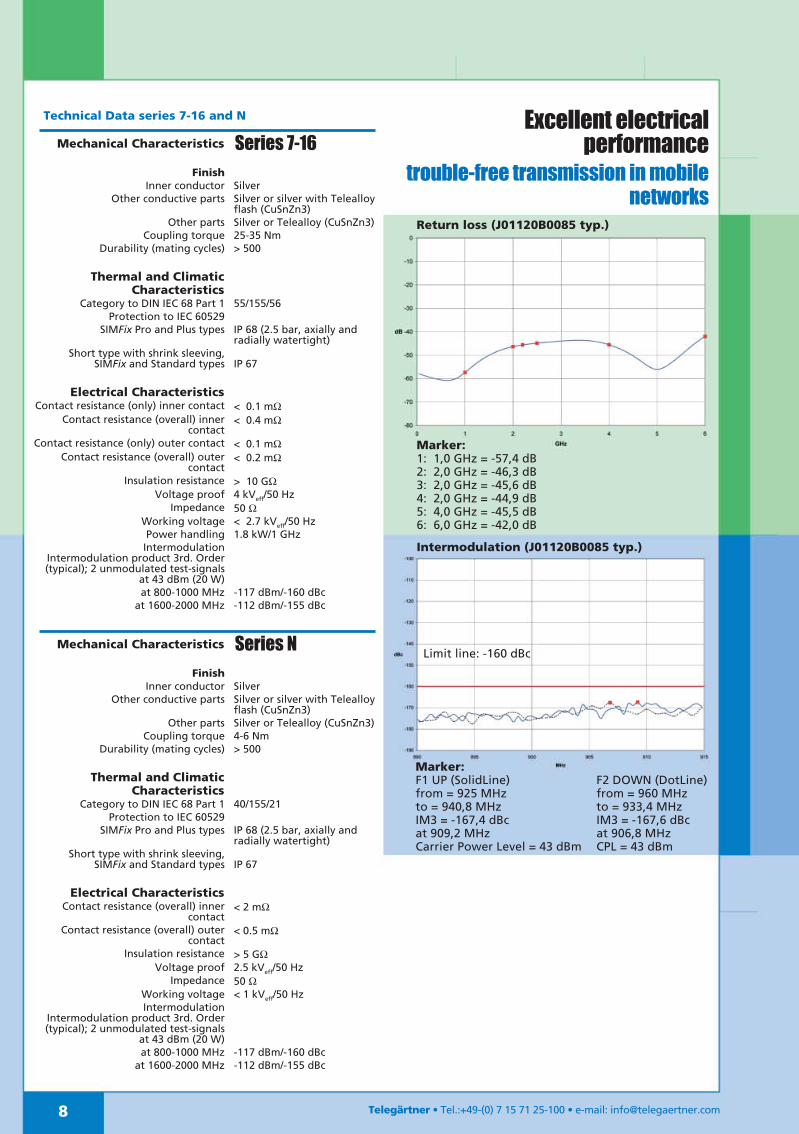
Return loss (J01120B0085 typ.)
Marker:1: 1,0 GHz = -57,4 dB2: 2,0 GHz = -46,3 dB3: 2,0 GHz = -45,6 dB4: 2,0 GHz = -44,9 dB5: 4,0 GHz = -45,5 dB6: 6,0 GHz = -42,0 dB
Intermodulation (J01120B0085 typ.)
Limit line: -160 dBc
Marker:F1 UP (SolidLine)from = 925 MHzto = 940,8 MHzIM3 = -167,4 dBcat 909,2 MHzCarrier Power Level = 43 dBm
F2 DOWN (DotLine)from = 960 MHzto = 933,4 MHzIM3 = -167,6 dBcat 906,8 MHzCPL = 43 dBm
Excellent electricalperformance
trouble-free transmission in mobilenetworks
Mechanical Characteristics Series 7-16
FinishInner conductor Silver
Other conductive parts Silver or silver with Telealloyflash (CuSnZn3)
Other parts Silver or Telealloy (CuSnZn3)Coupling torque 25-35 Nm
Durability (mating cycles) > 500
Thermal and ClimaticCharacteristics
Category to DIN IEC 68 Part 1 55/155/56Protection to IEC 60529
SIMFix Pro and Plus types IP 68 (2.5 bar, axially andradially watertight)
Short type with shrink sleeving,SIMFix and Standard types IP 67
Electrical CharacteristicsContact resistance (only) inner contact < 0.1 mΩ
Contact resistance (overall) innercontact
< 0.4 mΩ
Contact resistance (only) outer contact < 0.1 mΩContact resistance (overall) outer
contact< 0.2 mΩ
Insulation resistance > 10 GΩVoltage proof 4 kVeff/50 Hz
Impedance 50 ΩWorking voltage < 2.7 kVeff/50 HzPower handling 1.8 kW/1 GHz
IntermodulationIntermodulation product 3rd. Order(typical); 2 unmodulated test-signals
at 43 dBm (20 W)at 800-1000 MHz -117 dBm/-160 dBc
at 1600-2000 MHz -112 dBm/-155 dBc
Mechanical Characteristics Series N
FinishInner conductor Silver
Other conductive parts Silver or silver with Telealloyflash (CuSnZn3)
Other parts Silver or Telealloy (CuSnZn3)Coupling torque 4-6 Nm
Durability (mating cycles) > 500
Thermal and ClimaticCharacteristics
Category to DIN IEC 68 Part 1 40/155/21Protection to IEC 60529
SIMFix Pro and Plus types IP 68 (2.5 bar, axially andradially watertight)
Short type with shrink sleeving,SIMFix and Standard types IP 67
Electrical CharacteristicsContact resistance (overall) inner
contact< 2 mΩ
Contact resistance (overall) outercontact
< 0.5 mΩ
Insulation resistance > 5 GΩVoltage proof 2.5 kVeff/50 Hz
Impedance 50 ΩWorking voltage < 1 kVeff/50 HzIntermodulation
Intermodulation product 3rd. Order(typical); 2 unmodulated test-signals
at 43 dBm (20 W)at 800-1000 MHz -117 dBm/-160 dBc
at 1600-2000 MHz -112 dBm/-155 dBc
Technical Data series 7-16 and N

9Telegärtner • Tel.:+49-(0) 7 15 71 25-100 • e-mail: [email protected]
1/2" flex
Series Design Type Weight Order-No. Assembly Tool Fig.
7-16 Straight plug SIMFix 170 g J01120A0073 B65 N00091A0004 1
7-16 Straight plug SIMFix Plus 170 g J01120A0077 B68 N00091A0013 1
7-16 Angle plug Short 250 g J01120A0042 B48 - 2
7-16 Straight jack SIMFix 160 g J01121A0114 B65 N00091A0004 3
7-16 Straight jack SIMFix Plus 160 g J01121A0120 B68 N00091A0013 3
N Straight plug SIMFix 170 g J01020A0098 B65 N00091A0004 4
N Straight plug SIMFix Plus 170 g J01020A0105 B68 N00091A0013 4
N Angle plug Short 240 g J01020A0074 B48 - 5
N Straight jack SIMFix 160 g J01021A0156 B65 N00091A0004 6
N Straight jack SIMFix Plus 160 g J01021A0163 B68 N00091A0013 6
Cable typesRFF 1/2"-50
FSJ4-50B UCF 12-50J SCF 12-50J
Eupen 5092 HPL50-1/2-SF
HFSC-1/2"
Connectors for1/2" highly flexible cables
Stripping Tool

10 Telegärtner • Tel.:+49-(0) 7 15 71 25-100 • e-mail: [email protected]
1/2"
Series Design Type Weight Order-No. Assembly Tool Fig.
Hand Electric7-16 Straight plug SIMFix Pro 180 g J01120B0085 B78 N00091A0015 N00091A0018 1
7-16 Angle plug Short 220 g J01120A0026 B42 - - 2
7-16 Straight jack SIMFix Pro 160 g J01121B0136 B78 N00091A0015 N00091A0018 3
N Straight plug SIMFix Pro 180 g J01020B0141 B78 N00091A0015 N00091A0018 4
N Angle plug Short 180 g J01020A0044 B42 - - 5
N Straight jack SIMFix Pro 160 g J01021B0174 B78 N00091A0015 N00091A0018 6
Connectors for1/2" corrugated cables
Cable types RF 1/2"-50 LCF 12-50 Eupen 5128 LDF4-50A HPL50-1/2 10D-SFCR HFC-1/2"
Stripping Tools
for electrical manualdrills

11Telegärtner • Tel.:+49-(0) 7 15 71 25-100 • e-mail: [email protected]
7/8"
Connectors for7/8" corrugated cables
Series Design Type Weight Order-No. Assembly Tool Fig.
Hand Electric7-16 Straight plug SIMFix Pro 300 g J01120B0084 B79 N00091A0014 N00091A0019 1
7-16 Straight jack SIMFix Pro 320 g J01121B0132 B79 N00091A0014 N00091A0019 2
N Straight plug SIMFix Pro 300 g J01020B0142 B79 N00091A0014 N00091A0019 3
N Straight jack SIMFix Pro 320 g J01021B0175 B79 N00091A0014 N00091A0019 4
Cable typesRF 7/8"-50 LCF 78-50
Eupen 5228 LDF5-50A HPL50-7/8 20D-SFCR HFC-7/8"
Stripping Tools
for electrical manualdrills

12
1 1/4"
Telegärtner • Tel.:+49-(0) 7 15 71 25-100 • e-mail: [email protected]
Series Design Type Weight Order-No. Assembly Tool Fig.
7-16 Straight plug SIMFix Pro 580 g J01120B0087 B80 R00200A0011 1
7-16 Straight jack SIMFix Pro 580 g J01121B0138 B80 R00200A0011 2
N Straight plug Standard 790 g J01020A0085 B54 - 3
N Straight jack Standard 790 g J01021A0127 B54 - 4
Cable types RF 1 1/4"-50 LCF 114-50 Eupen 5328 LDF6-50A HPL50- 1 1/4
Connectors for1 1/4" corrugated cables
Termination Tool Set for1 1/4" + 1 5/8" SIMFix ProOrder-No. R00200A0011

13
1 5/8"
Telegärtner • Tel.:+49-(0) 7 15 71 25-100 • e-mail: [email protected]
Series Design Type Weight Order-No. Assembly Tool Fig.
7-16 Straight plug SIMFix Pro 900 g J01120B0088 B81 R00200A0011 1
7-16 Straight jack SIMFix Pro 900 g J01121B0139 B81 R00200A0011 2
N Straight plug Standard 1300 g J01020A0083 B55 - 3
N Straight jack Standard 1300 g J01021A0058 B55 - 4
Cable typesRF 1 5/8"-50 LCF 158-50
Eupen 5438 LDF7-50A
HPL50-1 5/8" HFC-1 5/8"
Connectors for1 5/8" corrugated cables
Termination Tool Set for1 1/4" + 1 5/8" SIMFix ProOrder-No. R00200A0011
Telegärtner • Tel.:+49-(0) 7 15 71 25-100 • e-mail: [email protected]
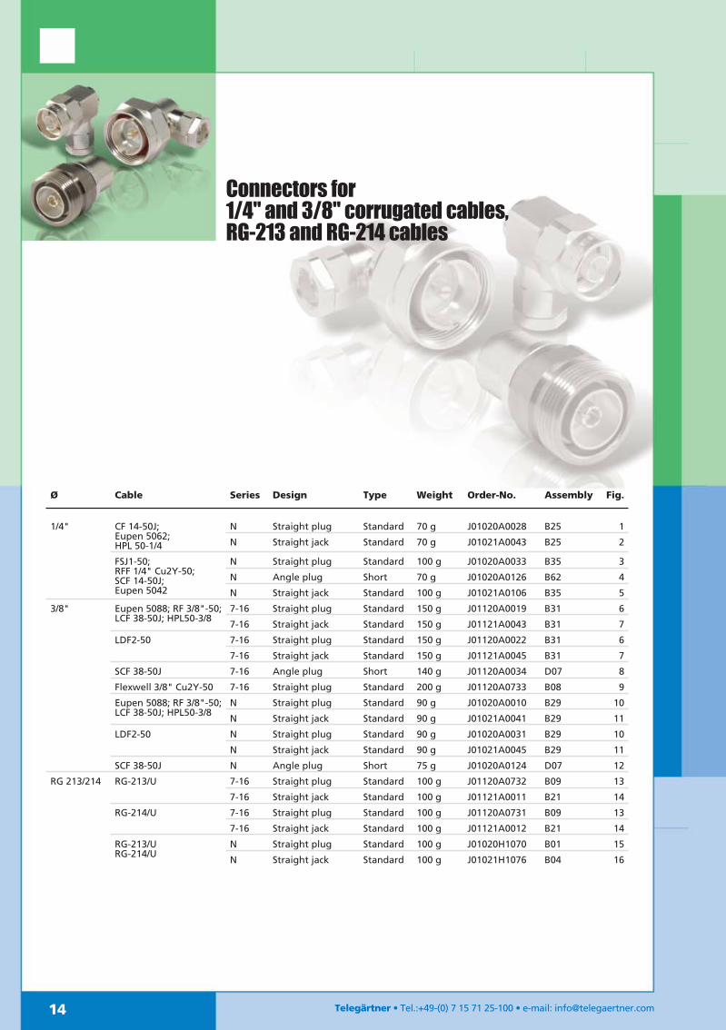
Ø Cable Series Design Type Weight Order-No. Assembly Fig.
1/4" CF 14-50J;Eupen 5062;HPL 50-1/4
N Straight plug Standard 70 g J01020A0028 B25 1
N Straight jack Standard 70 g J01021A0043 B25 2
FSJ1-50;RFF 1/4" Cu2Y-50;SCF 14-50J;Eupen 5042
N Straight plug Standard 100 g J01020A0033 B35 3
N Angle plug Short 70 g J01020A0126 B62 4
N Straight jack Standard 100 g J01021A0106 B35 5
3/8" Eupen 5088; RF 3/8"-50;LCF 38-50J; HPL50-3/8
7-16 Straight plug Standard 150 g J01120A0019 B31 6
7-16 Straight jack Standard 150 g J01121A0043 B31 7
LDF2-50 7-16 Straight plug Standard 150 g J01120A0022 B31 6
7-16 Straight jack Standard 150 g J01121A0045 B31 7
SCF 38-50J 7-16 Angle plug Short 140 g J01120A0034 D07 8
Flexwell 3/8" Cu2Y-50 7-16 Straight plug Standard 200 g J01120A0733 B08 9
Eupen 5088; RF 3/8"-50;LCF 38-50J; HPL50-3/8
N Straight plug Standard 90 g J01020A0010 B29 10
N Straight jack Standard 90 g J01021A0041 B29 11
LDF2-50 N Straight plug Standard 90 g J01020A0031 B29 10
N Straight jack Standard 90 g J01021A0045 B29 11
SCF 38-50J N Angle plug Short 75 g J01020A0124 D07 12
RG 213/214 RG-213/U 7-16 Straight plug Standard 100 g J01120A0732 B09 13
7-16 Straight jack Standard 100 g J01121A0011 B21 14
RG-214/U 7-16 Straight plug Standard 100 g J01120A0731 B09 13
7-16 Straight jack Standard 100 g J01121A0012 B21 14
RG-213/URG-214/U
N Straight plug Standard 100 g J01020H1070 B01 15
N Straight jack Standard 100 g J01021H1076 B04 16
Connectors for1/4" and 3/8" corrugated cables,RG-213 and RG-214 cables
15
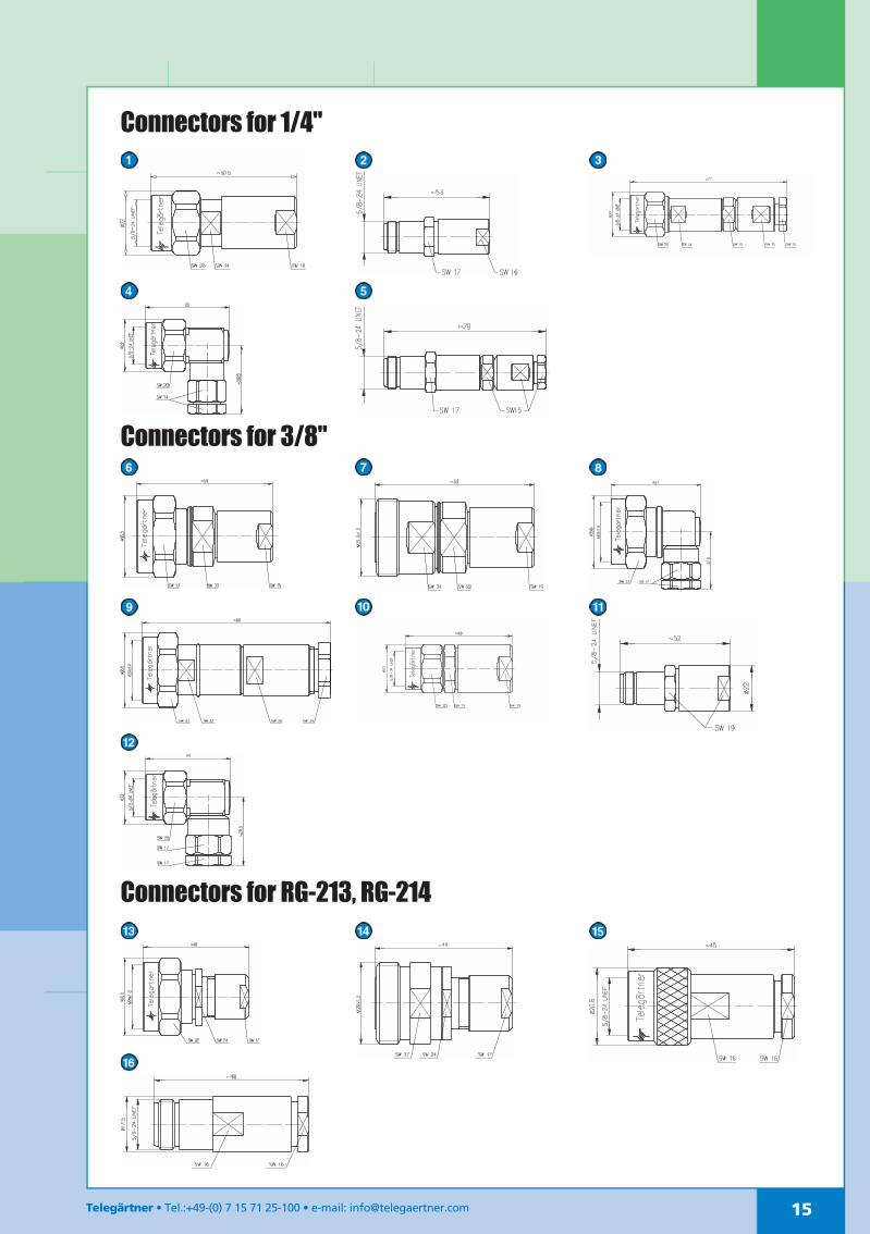
Connectors for 1/4"
Connectors for 3/8"
Connectors for RG-213, RG-214
Telegärtner • Tel.:+49-(0) 7 15 71 25-100 • e-mail: [email protected]

16 Telegärtner • Tel.:+49-(0) 7 15 71 25-100 • e-mail: [email protected]
Ø Cable Cable type Design Order-No. Type IP Class Weight Assembly
RG-213/U B Straight plug J01120A0732 Standard IP 67 100 g B09
Straight jack J01121A0011 Standard IP 67 100 g B21
RG-214/U B Straight plug J01120A0731 Standard IP 67 100 g B09
Straight jack J01121A0012 Standard IP 67 100 g B21
3/8" Eupen 5088;RF 3/8"-50; LCF 38-50J;HPL50-3/8
F Straight plug J01120A0019 Standard IP 68 150 g B31
Straight jack J01121A0043 Standard IP 68 150 g B31
LDF2-50 F Straight plug J01120A0022 Standard IP 68 150 g B31
Straight jack J01121A0045 Standard IP 68 150 g B31
SCF 38-50J J Angle plug J01120A0034 Short IP 54 140 g D07
Flexwell 3/8" Cu2Y-50 F Straight plug J01120A0733 Standard IP 67 200 g B08
1/2" Flex RFF1/2"-50; FSJ-50B;UCF 12-50J; SCF 12-50J;Eupen 5092;HFSC-1/2"-SF;HPL50-1/2-SF
J Straight plug J01120A0073 SIMFix IP 67 170 g B65
Straight plug J01120A0077 SIMFix Plus IP 68 170 g B68
Angle plug J01120A0042 Short IP 54 250 g B48
Straight jack J01121A0114 SIMFix IP 67 160 g B65
Straight jack J01121A0120 SIMFix Plus IP 68 160 g B68
1/2" RF 1/2"-50; LCF 12-50;Eupen 5128;LDF4-50A;HPL50-1/2;HFC-1/2"; 10D-SFCR
F/X Straight plug J01120B0085 SIMFix Pro IP 68 180 g B78
Angle plug J01120A0026 Short IP 54 220 g B42
Straight jack J01121B0136 SIMFix Pro IP 68 160 g B78
7/8" RF 7/8"-50; LCF 78-50;Eupen 5228; LDF5-50A;HPL50-7/8; HFC-7/8";20D-SFCR
F Straight plug J01120B0084 SIMFix Pro IP 68 300 g B79
Straight jack J01121B0132 SIMFix Pro IP 68 320 g B79
RFXT 7/8"-50 X Straight plug* J01120A0050 SIMFix IP 67 450 g B53
Straight jack* J01121A0086 SIMFix IP 67 440 g B53
RFF 7/8"-50 J Straight plug J01120A0051 Short IP 54 265 g B52
Straight jack J01121A0090 Short IP 54 255 g B52
1 1/4" RF 1 1/4"-50;RFX 1 1/4"; LCF 114-50;Eupen 5328; LDF6-50;HPL50-1 1/4;
F Straight plug J01120B0087 SIMFix Pro IP 68 580 g B80
Straight jack J01121B0138 SIMFix Pro IP 68 580 g B80
1 5/8" RF 1 5/8"-50;LCF 158"-50;Eupen 5438; LDF7-50;HPL50-1 5/8; HFC-1 5/8"
F Straight plug J01120B0088 SIMFix Pro IP 68 900 g B81
Straight jack J01121B0139 SIMFix Pro IP 68 900 g B81
Packaging: Individually packed in PE foil, together with assembly instruction
* With integrated earthing wire
B: Braided CableF: Feeder Cable (with annular corrugated outer conductor)J: Jumper Cable (with spiral corrugated outer conductor)X: Radiating Cable
7-16 (DIN) ConnectorsOverview

17Telegärtner • Tel.:+49-(0) 7 15 71 25-100 • e-mail: [email protected]
Packaging: Individually packed in PE foil, together with assembly instruction
* With integrated earthing wire
B: Braided CableF: Feeder Cable (with annular corrugated outer conductor)
J: Jumper Cable (with spiral corrugated outer conductor)X: Radiating Cable
N ConnectorsOverview
Ø Cable Cable type Design Order-No. Type IP Class Weight Assembly
RG-213/URG-214/U
B Straight plug J01020H1070 Standard IP 67 60 g B01
Straight jack J01021H1076 Standard IP 67 60 g B04
1/4" CF 14-50J;Eupen 5062;HPL50-1/4
F Straight plug J01020A0028 Standard IP 67 70 g B25
Straight jack J01021A0043 Standard IP 67 70 g B25
FSJ1-50; RFF 1/4"Cu2Y-50; SCF 14-50;Eupen 5042
F Straight plug J01020A0033 Standard IP 67 100 g B35
Angle plug J01020A0126 Short IP 54 70 g B62
Straight jack J01021A0106 Standard IP 54 100 g B35
3/8" Eupen 5088; RF 3/8"-50;LCF 38-50J; HPL50-3/8
F Straight plug J01020A0010 Standard IP 54 90 g B29
Straight jack J01021A0041 Standard IP 54 90 g B29
LDF2-50 F Straight plug J01020A0031 Standard IP 54 90 g B29
Straight jack J01021A0045 Standard IP 54 90 g B29
SCF 38-50J (HCF 3/8") J Angle plug J01020A0124 Short IP 54 75 g D07
1/2" Flex RFF1/2"-50; FSJ-50B;UCF 12-50J; SCF 12-50J;Eupen 5092; HPL50-1/2;HFSC-1/2"-SF
J Straight plug J01020A0098 SIMFix IP 67 170 g B65
Straight plug J01020A0105 SIMFix Plus IP 68 170 g B68
Angle plug J01020A0074 Short IP 54 240 g B48
Straight jack J01021A0156 SIMFix IP 67 160 g B65
Straight jack J01021A0163 SIMFix Plus IP 68 160 g B68
1/2" RF 1/2"-50; LCF 12-50;Eupen 5128; LDF4-50A;HPL50-1/2; HFC 1/2";10D-SFCR;
F/X Straight plug J01020B0141 SIMFix Pro IP 68 180 g B78
Angle plug J01020A0044 Short IP 54 180 g B42
Straight jack J01021B0174 SIMFix Pro IP 68 160 g B78
7/8" RF 7/8"-50; LCF 78-50;Eupen 5228; LDF5-50A;HPL50-7/8; HFC-7/8";20D-SFCR
F Straight plug J01020B0142 SIMFix Pro IP 68 300 g B79
Straight jack J01021B0175 SIMFix Pro IP 68 320 g B79
RFXT 7/8"-50 X Straight plug* J01020A0077 SIMFix IP 67 450 g B53
Straight jack* J01021A0052 SIMFix IP 67 450 g B53
RFF 7/8"-50 J Straight plug J01020A0099 Short IP 54 265 g B52
Straight jack J01021A0157 Short IP 54 265 g B52
1 1/4" RF 1 1/4"-50;RFX 1 1/4"-50;Eupen 5328; LDF6-50;HPL50-1 1/4;
F Straight plug J01020A0085 Standard IP 68 790 g B54
Straight jack J01021A0127 Standard IP 68 790 g B54
1 5/8" RF 1 5/8"-50;Eupen 5438; LDF7-50;HPL50-1 5/8;LCF 158-50J; HFC-1 5/8"
F Straight plug J01020A0083 Standard IP 68 1300 g B55
Straight jack J01021A0058 Standard IP 68 1300 g B55

18 Telegärtner • Tel.:+49-(0) 7 15 71 25-100 • e-mail: [email protected]
To protect against EMP caused by lightning stri-kes in the direct vicinity of base stations, Tele-gärtner has developed a range of surge sup-pressors wit 7/16- and N-Series interfaces.There are two different functional designs:
Surge suppressors with Gas Discharge Tube Quarter Wavelength Shorting Stub - with or
without DC pass
Surge Suppressors
19Telegärtner • Tel.:+49-(0) 7 15 71 25-100 • e-mail: [email protected]
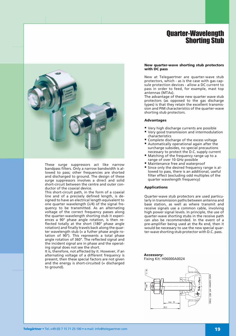
Quarter-WavelengthShorting Stub
These surge suppressors act like narrowbandpass filters. Only a narrow bandwidth is al-lowed to pass; other frequencies are shortedand discharged to ground. The design of thesesurge suppressors involves a direct and solidshort-circuit between the centre and outer con-ductor of the coaxial device.This short-circuit path, in the form of a coaxialline and of a precisely defined length, is de-signed to have an electrical length equivalent toone quarter wavelength (λ/4) of the signal fre-quency to be transmitted. As an alternatingvoltage of the correct frequency passes alongthe quarter-wavelength shorting stub it experi-ences a 90° phase angle rotation, is then re-flected totally at the short (180° phase anglerotation) and finally travels back along the quar-ter wavelength stub (= a futher phase angle ro-tation of 90°). This represents a total phaseangle rotation of 360°. The reflected signal andthe incident signal are in phase and the operat-ing signal does not see the short.It is, therefore, not affected by it. However, if analternating voltage of a different frequency ispresent, then these special factors are not givenand the energy is short-circuited (= dischargedto ground).
New quarter-wave shorting stub protectorswith DC pass
New at Telegaertner are quarter-wave stubprotectors, which - as is the case with gas cap-sule protection devices - allow a DC current topass in order to feed, for example, mast topantennas (MTAs).The advantage of these new quarter wave stubprotectors (as opposed to the gas dischargetypes) is that they retain the excellent transmis-sion and PIM characteristics of the quarter-waveshorting stub protectors.
Advantages
Very high discharge currents are possible Very good transmission and intermodulation
characteristics Complete discharge of the excess voltage Automatically operational again after the
surcharge subsides, no special precautionsnecessary to protect the D.C. supply current Matching of the frequency range up to a
range of over 10 GHz possible Maintenance free and waterproof Since only the desired frequency range is al-
lowed to pass, there is an additional, usefulfilter effect (excluding odd multiples of thequarter wavelength frequency)
Applications
Quarter-wave stub protectors are used particu-larly in transmission paths between antenna andbase station, as well as where transmit andreceive signals use a common cable, involvinghigh power signal levels. In principle, the use ofquarter-wave shorting stubs in the receive pathcan also be recommended. In the event of apre-amplifier being used at the Rx end, then itwould be necessary to use the new special quar-ter-wave shorting stub protector with D.C. pass.
Accessory:Fixing Kit: H06000A0024

Telegärtner Tel.:+49-(0) 7 15 71 25-100 e-mail: [email protected]
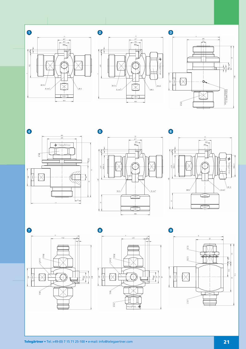
Product Overview/4 Shorting stub types
Type Frequency range (MHz) Fig.
380-430 800-9001710-2200
806-960 870-970 1700-1900 1700-2300 1850-2000 1920-2170 2250-2450
7-16 f-f J01125A0020 (9 J01125A0007 (1 J01125A0023 (10 J01125A0000 (1 J01125A0002 (4 J01125A0009 (4 J01125A0032 (4 1
7-16 m-f J01125A0019 (9 J01125A0008 (1 J01125A0024 (10 J01125A0001 (1 J01125A0003 (4 J01125A0017 (4 J01125A0010 (4 J01125A0021 (4 J01125A0016 (7 2
7-16 f-f(Bulkhead)
J01125A0011 (2 EWA940108-00 (2 EWA940108-10 (6 J01125A0013 (6 3
7-16 m-f(Bulkhead)
J01125A0012 (3 J01125A0031 (10 J01125A0006 (3 J01125A0015 (5 J01125A0014 (5 4
7-16 f-fDC-Pass*
J01125A0029 (10 5
7-16 m-fDC-Pass*
J01125A0030 (10 6
N f-f J01028A0015 (4 EWA950200-00 (8 EWA50200-30 (4 J01028A0020 (4 J01028A0017 (4 J01028A0019 (7 7
N m-f J01028A0016 (1 J01028A0008 (1 J01028A0009 (4 J01028A0021 (4 J01028A0018 (4 J01028A0022 (7 8
N f-f(Bulkhead)
J01028A0029 (9 J01028A0028(11 9
Intermodulation Performance(PIM 3rd. order) < -160 dBc
Return Loss Tri-Band-Type (J01125A0024) Technical Data
Mechanical Characteristics
Materials Spring contact CuBe2
Other metal parts CuZn39Pb3
Insulators PTFE
Gaskets Silicon
Finish Spring contact Cu2Ag5
Other metal parts CuSnZn3
Coupling torque series N 4-6 Nm
Coupling torque series 7-16 25-35 Nm
Durability (mating cycles) > 500
Thermal and Climatic Characteristics
Category to DIN IEC68 Part 1
Series N 40/155/21
Series 7-16 55/155/56
Protection level to DIN 40050/IEC 529 IP 67
Electrical Characteristics
VSWR < 1.15
Insertion loss < 0.1 dB
Intermodulation Intermodulation product 3rd Order (typical)
at 800-1000 MHz -160 dBc
2 unmodulated test-signals at 43dBm (20W)
at 1600-2000 MHz -155 dBc
max. power at 2200 MHz 500 W
Max. DischargeCurrent
Standard Types of quarter-wave shorting stubs
100 kA (8/50 µs testimpulses)
Types with D.C Pass 30 kA (8/50 µs testimpulses, multiple)
Maximum Working Voltage for D.C.-pass types 85 V
Dimensions (compare to drawings):7) Dimension a=97 mm; 2) Dimension a=98 mm; 3) Dimension a=102 mm; 4) Dimension a=64 mm; 5) Dimension a=69 mm; 6) Dimension a=65 mm;7) Dimension a=59 mm; 8) Dimension a=92 mm; 9) Dimension a=178 mm; 10) Dimension a=72 mm; 11) Dimension a=58,5 mm* 100 V (Operating voltage)
Marker1: 810 MHz = -27,3 dB2: 960 MHz = -25,6 dB3: 1710 MHz = -35,4 dB4: 2200 MHz = -33,9 dB
21Telegärtner • Tel.:+49-(0) 7 15 71 25-100 • e-mail: [email protected]

22 Telegärtner • Tel.:+49-(0) 7 15 71 25-100 • e-mail: [email protected]
Surge Suppressorswith Gas Discharge Tube
Voltage Surge Protection with Gas DischargeTube
The method of operation of this device can be like-ned in principle to an electrical switch which, whena certain voltage (d.c. sparkover voltage) is reached,switches the inner conductor to ground. The designof this device consists of a Gas Discharge Tube instal-led directly between the inner and outer conductorsof a coaxial line. When a higher voltage than the im-pulse sparkover voltage (= overvoltage) appears onthe line, the Gas Discharge Tube will fire and, de-pending on the prevalent energy, a glow dischargeof between 75-90V (current in milliampere range) orionisation with an arc voltage of 10-20V (currentsranging from amps to kiloamps) takes place. Whenthe energy subsides (= is converted to heat), thedischarge extinguishes itself automatically. After acooling-down period of 30 secs., the Gas DischargeTube is fully operational again. After several veryhigh discharge currents occurring within a few se-conds of each other, the functionality of the devicemay be impaired. It is recommended, therefore, thatthe gas capsules are replaced at certain intervals.
Advantages
Broad-band applications (to around 2.5 GHz) Transmission of DC voltages possible, e.g. remote
feeding of antenna amplifiers over the coaxial cable Maximum impulse Discharge current up to 40 KA Different variants available from 75 to 1400 V Installation in a waterproof unit
Applications
The main usage of the surge suppressor with gas dis-charge tube is between the antenna and the basestation. For high power signal transmission lines, λ/4surge arrestors are recommended, as the non-linearcharacteristics of the gas cartridge can produceintermodulation products.
Selection of suitable lightning protector withgas discharge tube
Generally speaking, the spark-over voltage of thedischarge tube should be kept as low as possible.However, in order to avoid an unintentionalignition of the tube, the spark-over voltage shouldbe at least twice the peak voltage occuring undernormal working conditions.
Example:
P = 100W; Z=50 Ω (with VSWR 1:1)
Peak voltage = umax = P Z× = 71 VRecommended spark-over voltage =2 × umax = 142 V
Most suitable Lightning Protector is145 V Type (J01028A0006)
23Telegärtner • Tel.:+49-(0) 7 15 71 25-100 • e-mail: [email protected]
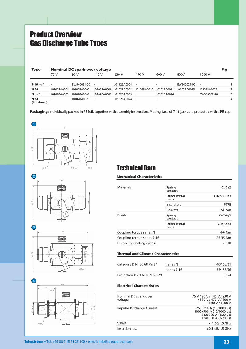
Product OverviewGas Discharge Tube Types
Type Nominal DC spark-over voltage Fig.75 V 90 V 145 V 230 V 470 V 600 V 800V 1000 V
7-16 m-f - EW940021-00 - J01125A0004 - - EW940021-00 - 1
N f-f J01028A0004 J01028A0000 J01028A0006 J01028A0002 J01028A0010 J01028A0011 J01028A0025 J01028A0026 2
N m-f J01028A0005 J01028A0001 J01028A0007 J01028A0003 - J01028A0014 - EW930092-20 3
N f-f(Bulkhead)
- J01028A0023 - J01028A0024 - - - - 4
Packaging: Individually packed in PE foil, together with assembly instruction. Mating-face of 7-16 jacks are protected with a PE-cap
Technical DataMechanical Characteristics
Materials Springcontact
CuBe2
Other metalparts
CuZn39Pb3
Insulators PTFE
Gaskets Silicon
Finish Springcontact
Cu2Ag5
Other metalparts
CuSnZn3
Coupling torque series N 4-6 Nm
Coupling torque series 7-16 25-35 Nm
Durability (mating cycles) > 500
Thermal and Climatic Characteristics
Category DIN IEC 68 Part 1 series N 40/155/21
series 7-16 55/155/56
Protection level to DIN 60529 IP 54
Electrical Characteristics
Nominal DC spark-overvoltage
75 V / 90 V / 145 V / 230 V/ 350 V / 470 V / 600 V
/ 800 V / 1000 V
Impulse Discharge Current 2500x10 A (10/1000 µs)1000x500 A (10/1000 µs)
5x20000 A (8/20 µs)1x40000 A (8/20 µs)
VSWR < 1.06/1.5 GHz
Insertion loss < 0.1 dB/1.5 GHz

24 Telegärtner • Tel.:+49-(0) 7 15 71 25-100 • e-mail: [email protected]
Jumper Cables IP 68The jumper cables are fitted at both ends with 7-16 connectorsand/or N connectors. The cable is a highly flexible 1/2” corru-gated type. The very low intermodulation products of the jum-per cables are tested on special intermodulation test systems.They are tested up to a frequency of 2,2 GHz. The jumper ca-bles are waterproof and sealed to allow external use. Intermo-dulations test results for the Jumper cables are also available.(Order-N° U00100A0000)
Protection Classification IP 68
The 7-16 connectors also incorporate an additional seal bet-ween centre contact and connector housing in the ma-ting-face (barrier-seal).A 360° inductive solder of the outer conductor - apart fromcontributing to excellent PIM and Return Loss Characteristics -also provides additional protection against ingress of moisturein the event of the cable sheath being damaged
Very low intermodulation products (IMP3) Hexagonal fixing nuts for correct torque and high-contact
pressure Waterproof for external use Excellent return loss and attenuation Fully soldered inner- and outer conductor
3/8" Jumper cables and other cable size available on request
Plug - Jack (7-16)Cable 1/2" highly flexible corrugated cable
Length Order-No. Weight0.5 m L00010D0550 425 g
1.0 m L00010D0551 550 g
1.5 m L00011D0182 675 g
2.0 m L00011D0183 800 g
2.5 m L00012D0061 925 g
3.0 m L00012D0062 1050 g
4.0 m L00013D0056 1300 g
5.0 m L00013D0057 1550 g
Plug - Plug (7-16)Cable 1/2" highly flexible corrugated cable
Length Order-No. Weight0.5 m L00010D0552 425 g
1.0 m L00010D0553 550 g
1.5 m L00011D0184 675 g
2.0 m L00011D0185 800 g
2.5 m L00012D0063 925 g
3.0 m L00012D0064 1050 g
4.0 m L00013D0058 1300 g
5.0 m L00013D0059 1550 g
25Telegärtner • Tel.:+49-(0) 7 15 71 25-100 • e-mail: [email protected]
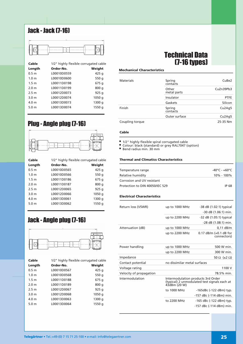
Jack - Jack (7-16)
Cable 1/2" highly flexible corrugated cable
Length Order-No. Weight0.5 m L00010D0559 425 g
1.0 m L00010D0600 550 g
1.5 m L00011D0198 675 g
2.0 m L00011D0199 800 g
2.5 m L00012D0073 925 g
3.0 m L00012D0074 1050 g
4.0 m L00013D0073 1300 g
5.0 m L00013D0074 1550 g
Plug - Angle plug (7-16)
Cable 1/2" highly flexible corrugated cable
Length Order-No. Weight0.5 m L00010D0565 425 g
1.0 m L00010D0566 550 g
1.5 m L00011D0186 675 g
2.0 m L00011D0187 800 g
2.5 m L00012D0065 925 g
3.0 m L00012D0066 1050 g
4.0 m L00013D0061 1300 g
5.0 m L00013D0062 1550 g
Jack - Angle plug (7-16)
Cable 1/2" highly flexible corrugated cable
Length Order-No. Weight0.5 m L00010D0567 425 g
1.0 m L00010D0568 550 g
1.5 m L00011D0188 675 g
2.0 m L00011D0189 800 g
2.5 m L00012D0067 925 g
3.0 m L00012D0068 1050 g
4.0 m L00013D0063 1300 g
5.0 m L00013D0064 1550 g
Mechanical Characteristics
Materials Springcontacts
CuBe2
Othermetal parts
CuZn39Pb3
Insulator PTFE
Gaskets Silicon
Finish Springcontacts
Cu2Ag5
Outer surface Cu2Ag5
Coupling torque 25-35 Nm
Cable
1/2" highly flexible spiral corrugated cable Colour: black (standard) or grey RAL7047 (option) Bend radius min. 30 mm
Thermal and Climatics Characteristics
Temperature range -40°C - +60°C
Relative humidity 10% - 100%
Corrosion and UV resistant
Protection to DIN 40050/IEC 529 IP 68
Electrical Characteristics
Return loss (VSWR) up to 1000 MHz -38 dB (1.02:1) typical
-30 dB (1.06:1) min.
up to 2200 MHz -32 dB (1.05:1) typical
-28 dB (1.08:1) min.
Attenuation (dB) up to 1000 MHz 0,11 dB/m
up to 2200 MHz 0.17 dB/m (+0.1 dB forconnectors)
Power handling up to 1000 MHz 500 W min.
up to 2200 MHz 300 W min.
Impedance 50 Ω (±2 Ω)
Contact potential no dissimilar metal surfaces
Voltage rating 1100 V
Velocity of propagation 78.5% min.
Intermodulation Intermodulation products 3rd Order(typical) 2 unmodulated test signals each at43dBm (20 W)
to 1000 MHz -165dBc (-122 dBm) typ.
-157 dBc (-114 dBm) min.
to 2200 MHz -165 dBc (-122 dBm) typ.
-157 dBc (-114 dBm) min.
Technical Data(7-16 types)
26 Telegärtner • Tel.:+49-(0) 7 15 71 25-100 • e-mail: [email protected]
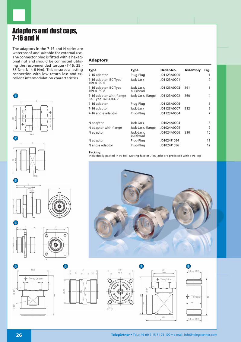
Adaptors and dust caps,7-16 and NThe adaptors in the 7-16 and N series arewaterproof and suitable for external use.The connector plug is fitted with a hexag-onal nut and should be connected utilis-ing the recommended torque (7-16: 25 -35 Nm; N: 4-6 Nm). This ensures a lastingconnection with low return loss and ex-cellent intermodulation characteristics.
Adaptors
Type Type Order-No. Assembly Fig.7-16 adaptor Plug-Plug J01123A0000 1
7-16 adaptor IEC Type169-4 IEC-6
Jack-Jack J01123A0001 2
7-16 adaptor IEC Type169-4 IEC-8
Jack-Jack,bulkhead
J01123A0003 Z61 3
7-16 adaptor with flangeIEC Type 169-4 IEC-7
Jack-Jack, flange J01123A0002 Z60 4
7-16 adaptor Plug-Plug J01123A0006 5
7-16 adaptor Jack-Jack J01123A0007 Z12 6
7-16 angle adaptor Plug-Plug J01123A0004 7
N adaptor Jack-Jack J01024A0004 8
N adaptor with flange Jack-Jack, flange J01024A0005 9
N adaptor Jack-Jack,bulkhead
J01024A0006 Z10 10
N adaptor Plug-Plug J01024J1094 11
N angle adaptor Plug-Plug J01024J1096 12
Packing:Individually packed in PE foil. Mating-face of 7-16 jacks are protected with a PE-cap

27Telegärtner • Tel.:+49-(0) 7 15 71 25-100 • e-mail: [email protected]
Inter Series Adaptors 7-16 – N
Type Order-No. Fig.7-16 Jack-N Jack J01122A0008 1
7-16 Plug-N Plug J01122A0009 2
7-16 Plug-N Jack J01122A0010 3
7-16 Jack-N Plug J01122A0011 4
Dust caps
Type Order-No. Fig.7-16 dust cap for Jacks H00070A0000 5
7-16 dust cap for Plugs H00070A0001 6
N dust cap for Jacks H00010A1122 7
28 Telegärtner • Tel.:+49-(0) 7 15 71 25-100 • e-mail: [email protected]
Tools and Accessories
Cutting Tools Cable Order-No.
Cutting Tool for SIMFix Pro connectorsJ01120B0085, J01121B0136, J01020B0141, J01021B0174
1/2" N00091A0015
Cutting Tool for SIMFix Pro connectorsJ01020A0098, J01021A0156, J01120A0073, J01121A0114
1/2"(flex) N00091A0004
Cutting Tool for SIMFix Plus connectorsJ01120A0077, J01121A0120, J01020A0105, J01021A0163
1/2"(flex) N00091A0013
Cutting Tool for SIMFix Pro connectorsJ01120B0084, J01121B0132, J01020B0142, J01021B0175
7/8" N00091A0014
Spare blade (4 large,1 small) for N00091A0014,N00091A0015 1/2"+ 7/8" N00099A0000Spare blade (2 round,1 small) for N00091A0004, N00091A0013 1/2"(flex) N00099A0001Rotating stripping Tool SIMFix ProJ01120B0085, J01121B0136, J01020B0141, J01021B0174
1/2" N00091A0018
Rotating stripping Tool SIMFix ProJ01120B0084, J01121B0132, J01020B0142, J01021B0175
7/8" N00091A0019
Termination Tool set for SIMFix Pro connectorsJ01120B0087, J01121B0138, J01120B0088, J01121B0139
1 1/4" + 1 5/8" R00200A0011
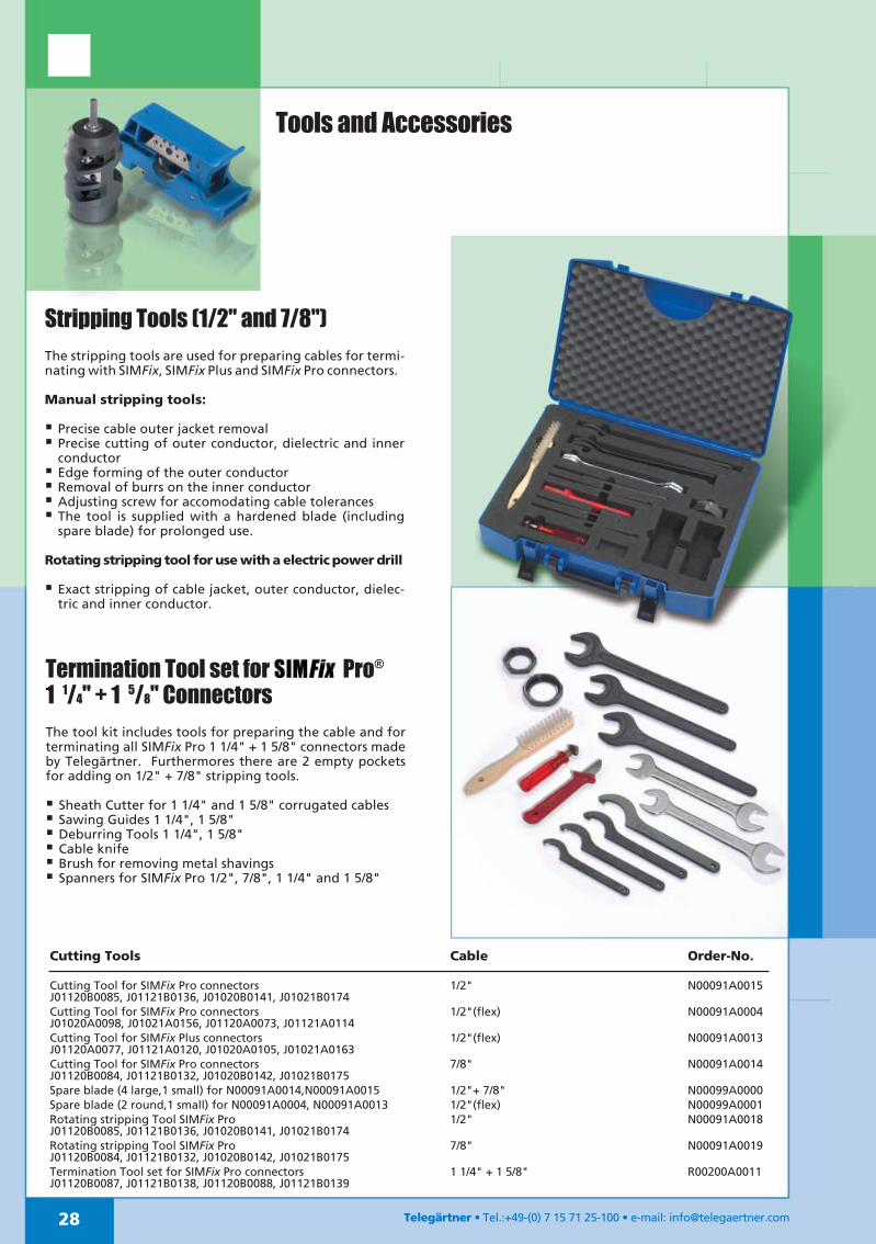
Stripping Tools (1/2" and 7/8")The stripping tools are used for preparing cables for termi-nating with SIMFix, SIMFix Plus and SIMFix Pro connectors.
Manual stripping tools:
Precise cable outer jacket removal Precise cutting of outer conductor, dielectric and inner
conductor Edge forming of the outer conductor Removal of burrs on the inner conductor Adjusting screw for accomodating cable tolerances The tool is supplied with a hardened blade (including
spare blade) for prolonged use.
Rotating stripping tool for use with a electric power drill
Exact stripping of cable jacket, outer conductor, dielec-tric and inner conductor.
Termination Tool set for Pro®
1 1/4" + 1 5/8" ConnectorsThe tool kit includes tools for preparing the cable and forterminating all SIMFix Pro 1 1/4" + 1 5/8" connectors madeby Telegärtner. Furthermores there are 2 empty pocketsfor adding on 1/2" + 7/8" stripping tools.
Sheath Cutter for 1 1/4" and 1 5/8" corrugated cables Sawing Guides 1 1/4", 1 5/8" Deburring Tools 1 1/4", 1 5/8" Cable knife Brush for removing metal shavings Spanners for SIMFix Pro 1/2", 7/8", 1 1/4" and 1 5/8"

29Telegärtner • Tel.:+49-(0) 7 15 71 25-100 • e-mail: [email protected]
Spanner, Sheath Cutter, Open ended wrench
For terminating connectors on 1 1/4" and 1 5/8" corrugatedcables (already included in Tool kit).
Sawing guide
For terminating connectors on 1 1/4" and 1 5/8" corrugatedcables (already included in tool kit).
Adhesive Shrink-Sleeves
An adhesive shrink-sleeve is required for the short bodiedconnector to ensure waterproofing. (Not required for SIMFix, -Plusand -Pro connectors)These are fitted over the junction between the connector andcable. By applying heat the adhesive process begins, so that theadhesive shrink-sleeve follows the exact contours of the connectorand cable junction. This distributes the adhesive on the inside ofthe sleeve and, on cooling and hardening, provides a watertightjoint.
Fixing kit for /4 Shorting Stubs
For mounting λ/4 Shorting Stubs on (earthing) bus bars.Contents: Bolt, hex. locking nut, lock washer
Mounting kit for /4 shorting stubsOrder-No. H06000A0024
Spanner und Sheath Cutter Cable Order-No.Spanner DIN 1810-B52-55 for J01120B0087, J01121B0138 1 1/4" N00050A0001
Sheath Cutter for J01120B0087, J01121B0138 1 1/4" N00080A0004
Spanner DIN 1810-B68-75 for J01120B0088, J01121B0139 1 5/8" N00050A0003
Sheath Cutter for J01120B0088, J01121B0139 1 5/8" N00080A0005
Double open ended wrench AF24/27 for J01120B0085,J01121B0136, J01020B0141, J01021B0174, J01020B0142,J01021B0175
1/2" + 7/8" N00050A0006
Open ended wrench AF36 for J01120B0084, J01121B0132,J01020B0142, J01021B0175, J01120B0087, J01121B0138
7/8" + 1 1/4" N00050A0007
Sawing Guide Cable Order-No.Sawing Guide for J01120B0087, J01121B0138 1 1/4" N00091A0016
Sawing Guide for J01120B0088, J01121B0139 1 5/8" N00091A0017
Adhesive Shrink-Sleeves Length Cable Order-No.Adhesive Shrink-Sleeves for short connectors (l=70 mm) 1/4" B00101A0008
Adhesive Shrink-Sleeves for short connectors (l=70 mm) 3/8" + 1/2" B00102A0005
Adhesive Shrink-Sleeves for short connectors (l=100 mm) 7/8" B00103A0000

Protection against touch and foreign bodies* Protection against water*
First CodeNumber
Description Second CodeNumber
Description
0 No particular protection 0 No particular protection
1 Protection against ingress of solid foreignbodies with a diameter over 50 mm
1 Protection against dripping water
2 Protection against solid foreign bodies witha diameter over 12.5 mm
2 Protection against vertically dripping water.There must be no harmful effect on materialstipped (in a container) up to 15° from itsnormal position.
3 Protection against ingress of solid foreignbodies with a diameter over 2.5 mm
3 Protection against fine water spray
4 Protection against ingress of solid foreignbodies with a diameter over 1.0 mm
4 Protection against water spray
5 Dust protected 5 Protection against water jet
6 Dust-proof 6 Protection against strong water jet
7 Protection against water, when the material isimmersed in water
8 The material is suitable for continuoussubmersion in water
* Definitions see IEC 60529
Example of Classification in Accordance with the IP Code
Telegärtner • Tel.:+49-(0) 7 15 71 25-100 • e-mail: [email protected]
The degree of protection is classified according to IEC60529. The coding system used is the IP-Code (Interna-tional Protection). The coding denotes the level of pro-tection against the ingress of solid bodiess (first codenumber) and the ingress of water (second code number).
Classification of Degree of Protection
Performance Diagrams
Power derating by temperature
IP 6 7
Code Letter First Code Number Second Code Number
A housing with IP Classification
6 - No ingress of dust7 - When subjected to submersion in water at a definedpressure and for a defined length of time, the ingress ofwater must be so restricted that no damage is caused.Submersion Bath: Water level above the enclosure:0,15m measured from the top of the enclosure, 1,0mmeasured from the bottom of the enclosure.Duration ofTest: 30 mins.TG Specification for Simfix Connectors: height of waterlevel: 25m: is equivalent to 2.5 bar; duration of test: 24 hrs.
31
Return Loss Reflection Coefficient VSWR Return Loss Reflection Coefficient VSWR10 0.316 1.923 30.5 0.030 1.060
10.5 0.298 1.848 31 0.028 1.056
11 0.282 1.780 31.5 0.027 1.054
11.5 0.266 1.726 32 0.025 1.051
12 0.252 1.671 32.5 0.024 1.048
12.5 0.237 1.618 33 0.022 1.045
13 0.224 1.578 33.5 0.021 1.043
13.5 0.211 1.538 34 0.020 1.040
14 0.199 1.497 34.5 0.019 1.038
14.5 0.188 1.462 35 0.018 1.036
15 0.178 1.430 35.5 0.017 1.034
15.5 0.l65 1.396 36 0.016 1.032
16 0.158 1.374 36.5 0.015 1.030
16.5 0.150 1.350 37 0.014 1.028
17 0.141 1.329 37.5 0.013 1.027
17.5 0.133 1.304 38 0.013 1.025
18 0.126 1.285 38.5 0.012 1.022
18.5 0.119 1.268 39 0.011 1.021
19 0.112 1.251 39.5 0.011 1.020
19.5 0.106 1.235 40 0.010 1.020
20 0.100 1.220 40.5 0.009 1.018
20.5 0.094 1.208 41 0.009 1.017
21 0.089 1.193 41.5 0.008 1.016
21.5 0.084 1.180 42 0.008 1.015
22 0.079 1.171 42.5 0.008 1.014
22.5 0.075 1.160 43 0.007 1.013
23 0.071 1.151 43.5 0.007 1.012
23.5 0.067 1.142 44 0.006 1.012
24 0.063 1.133 44.5 0.006 1.011
24.5 0.060 1.124 45 0.005 1.011
25 0.057 1.118 45.5 0.005 1.011
25.5 0.053 1.111 46 0.004 1.010
26 0.050 1.105 46.5 0.004 1.009
26.5 0.047 1.100 47 0.004 1.008
27 0.045 1.094 47.5 0.004 1.008
27.5 0.042 1.088 48 0.004 1.008
28 0.040 1.082 48.5 0.004 1.008
28.5 0.038 1.078 49 0.004 1.007
29 0.035 1.073 49.5 0.003 1.007
29.5 0.034 1.069 50 0.003 1.006
30 0.032 1.064
Errors and omissions excepted!
Telegärtner • Tel.:+49-(0) 7 15 71 25-100 • e-mail: [email protected]
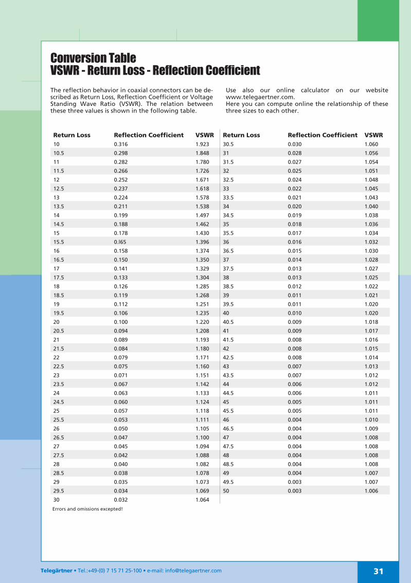
Conversion TableVSWR - Return Loss - Reflection CoefficientThe reflection behavior in coaxial connectors can be de-scribed as Return Loss, Reflection Coefficient or VoltageStanding Wave Ratio (VSWR). The relation betweenthese three values is shown in the following table.
Use also our online calculator on our websitewww.telegaertner.com.Here you can compute online the relationship of thesethree sizes to each other.
