technology (sut) for ball valve • for operating 2- and 3
TRANSCRIPT

AKM 105S, 115S: Rotary actuator with SAUTER UniversalTechnology (SUT) for ball valve
How energy efficiency is improvedAutomatic adaptation to ball valve, precise activation and high energy efficiency with minimal operat-ing noise.
Features• For operating 2- and 3-way ball valves VKR, VKRA, BKR, BKRA, VKAI, VKAA, BKLI, BKTI, BKTA,
(AKM115S) and 6-way ball valve B2KL• For controllers with constant output (0...10 V) or switching output (2-/3-point control)• Assembly with ball valve without the use of tools• Stepping motor with SAUTER Universal Technology (SUT) electronic control unit• Electronic force-dependent motor cut-off• Automatic recognition of applied control signal (continuous or switched)• Coding switch for selection of characteristic and running time (35 s, 60 s, 120 s)• Type of characteristic (linear/quadratic/equal-percentage) can be set on the actuator• Direction of operation can be selected directly on the cable• Maintenance-free gear unit• Gear unit can be disengaged in order to position the ball valve manually (using the lever)• Bracket and bayonet ring made of glass-fibre-reinforced plastic for fitting onto ball valve
Technical data
Power supplyPower supply 24 V~ ±20%, 50...60 HzPower supply 24 V= -10%...20%Power consumption 4.9 W/8.7 VA
ParametersRunning time1) 35/60/120 sAngle of rotation 90°Response time 200 msPower cable 1.2 m, 5 × 0.5 mm2
Positioner Positioning signal y 0...10 V, Ri > 100 kΩ
Positional feedback signal 0...10 V; load > 10 kΩStarting point U0 0 V or 10 V
Control span ΔU 10 VSwitching range Xsh 200 mV
Ambient conditionsTemperature of medium2) Max. 100 °CAdmissible ambient temperature –10...55 °CAdmissible ambient humidity 5...95% rh, no condensation
ConstructionFitting Vertically upright to horizontal,
not upside downWeight 0.7 kgHousing Lower section black, upper section
yellowHousing material Fire-retardant plastic
Standards and directivesType of protection IP54 as per EN 60529Protection class III as per IEC 60730
CE conformity according to EMC Directive 2014/30/EU EN 61000-6-1, EN 61000-6-3EN 61000-6-4
Directive 2006/95/EC Machine directive (EN 1050)
1) For a running time of 35 s, the torque is halved2) At media temperatures < 5 °C or > 100 °C, appropriate accessory must be used
Product data sheet 5.1 51.364
Right of amendment reserved © 2017 Fr. Sauter AG 1/7
AKM115SF132

Overview of typesType Torque
AKM105SF132 4 Nm
AKM115SF132 8 Nm
AccessoriesType Description
0313529001 Split-range unit for adjusting sequences, fitted in separate junction box
0372462001 CASE Drives PC tool for configuring the drives by computer
0510420001 Adaptor required when temperature of the medium > 100 °C
0510240011 Adaptor required when temperature of the medium < 5 °C
0510480001 Auxiliary change-over contacts, single
0510480002 Auxiliary change-over contacts, double
A Auxiliary change-over contacts: Infinitely variable 0...100%, admissible load 5(2) A, 24...230 V
Description of operationDepending on the type of connection (see connection diagram), the actuator can be used as a contin-uous 0...10 V, 2-point (OPEN/CLOSE) or 3-point actuator with an intermediate position(OPEN/STOP/CLOSE).The running time of the actuator can be set with the coding switch according to requirements. Thecoding switch can be used to select the equal-percentage, linear or quadratic characteristic. TheAKM 115 is combined with ball valves that have an equal-percentage basic characteristic like theVKR or BKR.The manual adjustment is performed by releasing the gear unit (slide switch beside the connectioncable) and simultaneously turning it with the lever. The actuator position can be determined by look-ing at the lever or the indicator knob on the top part of the actuator.
)NoteAfter manually adjusting the slide switch, put it back into its original position (engage gear unit).
Intended useThis product is only suitable for the purpose intended by the manufacturer, as described in the “De-scription of operation” section.All related product regulations must also be adhered to. Changing or converting the product is not ad-missible.
Additional technical dataThe upper section of the housing with the cover, indicator knob and cover knob contains the steppingmotor and the SUT electronics. The lower section of the housing contains the maintenance-free gearunit.
Auxiliary change-over contacts:• Switch rating max. 230 V VAC, current min. 20 mA at 20 V• Switch rating max. 4...30 V VDC, current 1...100 mA
Power consumptionType Running time [s] Status Active power P [W] Apparent power S [VA]AKM105SF132 35 Operation 2.45 4.75
Standstill 0.35 0.860 Operation 4.9 8.7
Standstill 0.35 0.75120 Operation 2.25 4.3
Standstill 0.35 0.75
Connection as 2-point actuatorThis OPEN/CLOSE activation can be performed via 2 cables. The actuator is connected to the volt-age via the blue and brown cables. The control passage of the ball valve is opened by connecting thevoltage to the black cable. After this voltage is switched off, the actuator moves to the opposite endposition and closes the ball valve.
Product data sheet 5.1 51.364
2/7 Right of amendment reserved © 2017 Fr. Sauter AG
AKM115SF132

The unused red and grey wires must not be connected or come into contact with other cables. Werecommend that you insulate these.
Connection as 3-point control unitWhen voltage is applied to the cable (brown or black), the ball valve is moved to any desired position.Direction of rotation (viewing the spindle of the ball valve from the actuator):• The stem turns in the clockwise direction, with voltage on the brown cable, and closes the ball
valve.• The stem turns in the anti-clockwise direction, with the voltage on the black cable.In the end positions (limit stop in actuator, max. angle of rotation of 95° reached) or in the case of anoverload, the electronic motor cut-off is activated (no limit switches). Direction of rotation changed bytransposing the connections.The unused red and grey wires must not be connected or come into contact with other cables. Werecommend that you insulate these.
Connection for control voltage 0...10 VThe built-in positioner controls the actuator depending on controller’s output signal y.Direction of rotation (viewing the spindle of the ball valve from the actuator):Direction of operation 1 (mains power supply on brown cable):When the positioning signal is increasing, the carrier stem turns in the anti-clockwise direction andopens the control passage of the ball valve.Direction of operation 2 (mains power supply on black cable):When the positioning signal is increasing, the carrier stem turns in the clockwise direction and closesthe control passage of the ball valve.The starting point and control span are fixed.Only the brown cable or the black cable may be connected to the voltage. The cable not used mustbe insulated (if not connected via switch).As the starting point and the control span are defined as fixed values, a split-range unit is available(accessory) for setting partial ranges.After a manual adjustment or a power failure of more than at least 5 min, the actuator automaticallyreadjusts itself, always with a running time of 60 s.After the power supply is connected, the stepping motor moves to the 100% position, makes the con-nection with the carrier stem, and then moves to the 0% position and thus defines the working range.After this, every position between a 0 and 90 ° angle of rotation can be achieved, depending on thecontrol voltage. Thanks to the electronics, no steps can be lost, and the actuator does not require pe-riodic re-adjustment. It is possible to operate multiple actuators of the same type in parallel. The feed-back signal y0 = 0...10 V corresponds to the effective angle of rotation of 0…90 °.When control signal 0…10 V is interrupted and direction of operation 1 is connected, the ball valve isclosed completely (0% position).The coding switch can be used to select the characteristic of the ball valve. Characteristics can onlybe generated when the actuator is used as a continuous actuator. The running times can be selectedwith additional switch settings. These can be used regardless of whether the 2-point, 3-point or con-tinuous function is selected.
Product data sheet 5.1 51.364
Right of amendment reserved © 2017 Fr. Sauter AG 3/7

Coding switch for running time and characteristic selection
switch position
55
91
0Y
25
57
0Y
M M
25
81
0Y
running time/angle of
rotation
s/90°
1 2 3
On
Off
120 s ± 4
1 2 3
On
Off
120 s ± 4
1 2 3
On
Off
Signal
stroke
120 s ± 4
1 2 3
On
Off
60 s ± 2
1 2 3
On
Off
60 s ± 2
1 2 3
On
Off
Signal
stroke
60 s ± 2
1 2 3
On
Off
35 s ± 1
1 2 3
On
Off
Signal
stroke
35 s ± 1
Split-range unit, accessory 0361529 001Starting point U0 and control span ∆U can be set with the potentiometer. In this way, several controlunits can be operated by the control signal in sequence or in cascade. The input signal (partial range)
Product data sheet 5.1 51.364
4/7 Right of amendment reserved © 2017 Fr. Sauter AG

is amplified into an output signal of 0...10V. This accessory cannot be built into the actuator but mustbe externally housed in an electrical junction box.
CASE Drives PC Tool, accessory 0372462 001CASE Drives allows you to set and read the actuator parameters on site. The connection is via a seri-al port on the PC (laptop) and a socket contact on the actuator. The set consists of: The software in-cluding installation and operating manual, fitting instructions, connection plug, cable (1.2 m long) andinterface converter for the PC. The application is designed for commissioning and service engineersas well as experienced operators.The last setting has priority, whether made with the coding switch or CASE Drives. When a change-over is made with the coding switch, this setting is active. In order that the settings made with CASEDrives cannot be overwritten, the coding switch can be removed before the setting (delivery includesspecial tool).
Notes on engineering and installationCondensate, dripping water, etc. must be prevented from entering the actuator along the carrier stem.When connecting the electricity supply, ensure that the cross-section of the power cable is adapted tothe power output and the length. However, we recommend a minimum cross-section of 0.75 mm².The actuator/ball valve is mounted by inserting and turning the bayonet ring until the limit stop withoutany additional adjustment. No tools are required. The coupling of the spindle of the ball valve with thecarrier stem is performed automatically, either by moving the manual adjuster to an angle of rotationof 100% or connecting the voltage. For dismantling, the bayonet ring is simply opened and the actua-tor removed. The device is delivered ex works in the middle position.The concept of stepping motor and electronics enables parallel operation of multiple actuators of thesame SUT type.If a potentiometer is required, the accessory of the AVM 105, 115 can be used - the display (% angleof rotation) on the type plate is inverted. The maximum accessory equipment for an actuator is 1 aux-iliary change-over contact or 1 potentiometer.The auxiliary change-over contact accessory is screwed onto the top cover of the actuator. To be ableto make the mechanical connection, you first have to remove the indicator knob. A new indicator canbe seen on the cover of the accessory.The coding switches are accessible via an opening with a black cover in the housing lid.Note The housing must not be opened.
Outdoor installationWe recommend protecting the devices from the weather if they are installed outside buildings.
DisposalWhen disposing of the product, observe the currently applicable local laws.More information on materials can be found in the Declaration on materials and the environment forthis product.
Connection diagram
mP
M
24 V~/=
MM 0201
A/D
05
y=
0...1
0V
y0=
0...1
0V
03
MM 0503
24 V~/=
open/stop/close
Variante 1 (3pt)
24 V~/=
open / close
Variante 2 (2pt)
BU BN RD GY
MM 01 0503
BU BKBN RD GY
BU RD GY
02
01
BKBN
02BK
RD = redBN = brownBK = blackBU = blueGY = grey
Product data sheet 5.1 51.364
Right of amendment reserved © 2017 Fr. Sauter AG 5/7
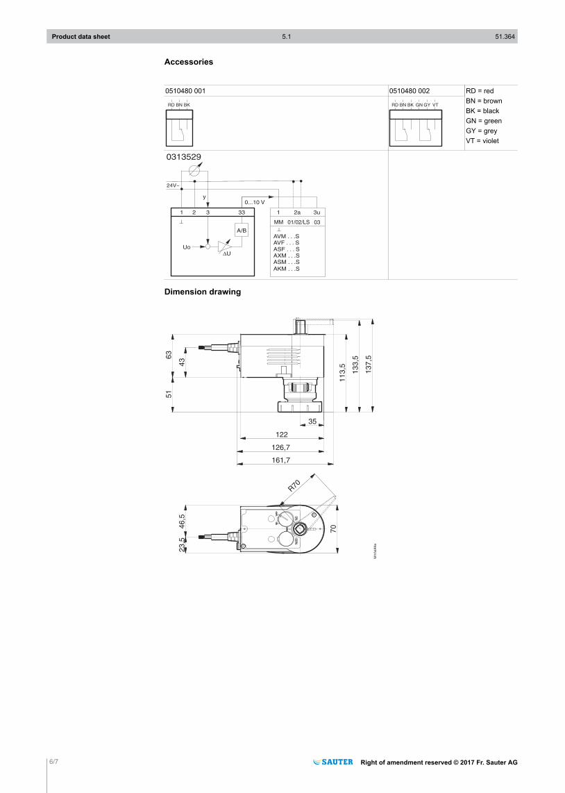
Accessories
0510480 001 0510480 002 RD = redBN = brownBK = blackGN = greenGY = greyVT = violet
RD BN BK RD BN BK GN GY VT
1 2 3 33
A/B
UoDU
24V~
^
1 2a 3u
^
AVM . . .SAVF . . . SASF . . . SAXM . . .SASM . . .S
AKM . . .S
0...10 V
0313529
y
MM 01/02/LS 03
Dimension drawing
Product data sheet 5.1 51.364
6/7 Right of amendment reserved © 2017 Fr. Sauter AG

Accessories
0510420001
60
Z1
02
22
Product data sheet 5.1 51.364
Right of amendment reserved © 2017 Fr. Sauter AG 7/7
Fr. Sauter AGIm Surinam 55
CH-4016 BaselTel. +41 61 - 695 55 55
www.sauter-controls.com